IP and Networking Basics. Outline Origins of TCP/IP OSI Stack & TCP/IP Architecture IP Addressing...
81
IP and Networking Basics
-
Upload
melvin-melvyn-warner -
Category
Documents
-
view
252 -
download
4
Transcript of IP and Networking Basics. Outline Origins of TCP/IP OSI Stack & TCP/IP Architecture IP Addressing...
IP and Networking Basics

Outline
Origins of TCP/IP OSI Stack & TCP/IP Architecture IP Addressing Large Network Issues Routers Types of Links Address Resolution Protocol
Origins of TCP/IP
1950’s – 1960’s – US Govt. requirement for “rugged” network
RAND Corporation – Distributed Network Design
1968 – ARPA engineers propose Distributed network design for ARPANET (Defense Advanced Research Project Agency Network)

Distributed Network Design
Pre-ARPANET networks– “connection oriented”– Management & control was centralized
“New” Network – ARPANET– Connectionless– Decentralised
Modern Internet has evolved from the ARPANET
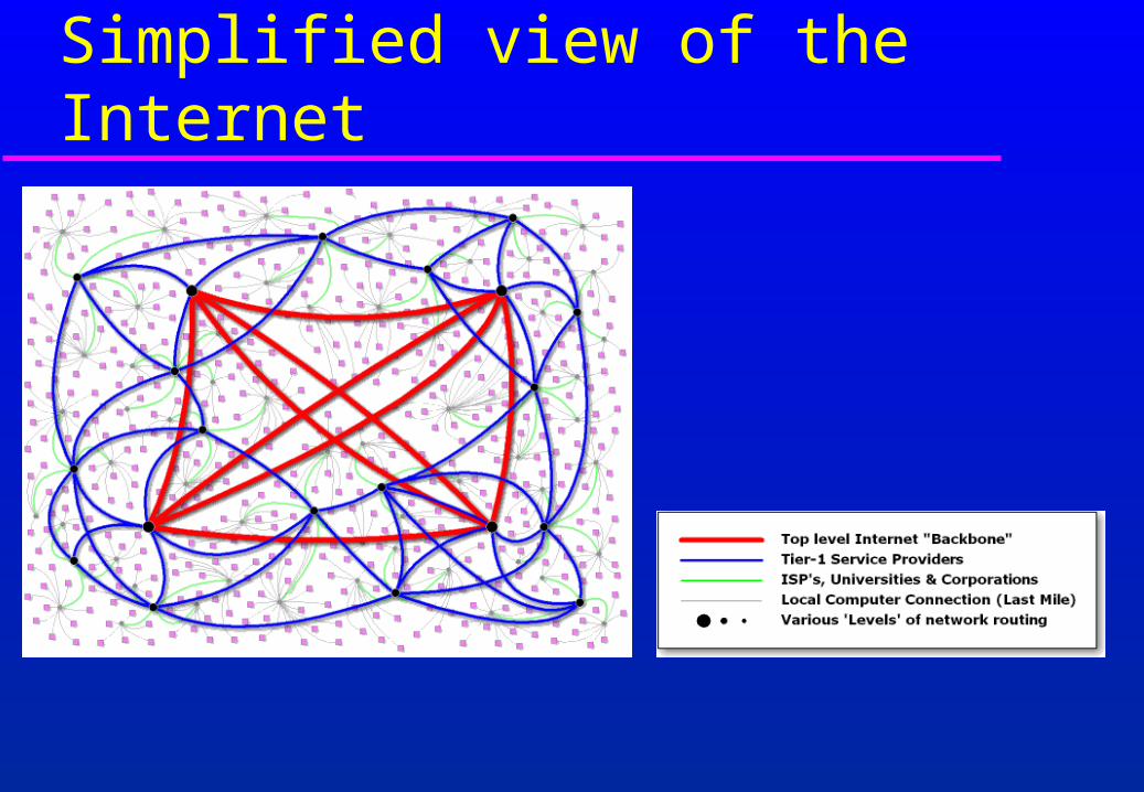
Simplified view of the Internet
What internetworks are Start with lots of little networks Many different types
– ethernet, dedicated leased lines, dialup, ATM, Frame Relay, FDDI
Each type has its own idea of addressing and protocols
Want to connect them all together and provide a unified view of the whole lot

A small internetwork, or “internet”
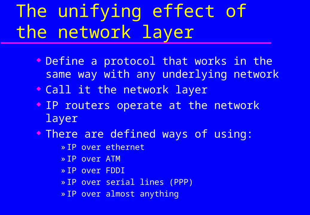
The unifying effect of the network layer
Define a protocol that works in the same way with any underlying network
Call it the network layer IP routers operate at the network layer There are defined ways of using:
» IP over ethernet» IP over ATM» IP over FDDI» IP over serial lines (PPP)» IP over almost anything
OSI Stack & TCP/IP Architecture
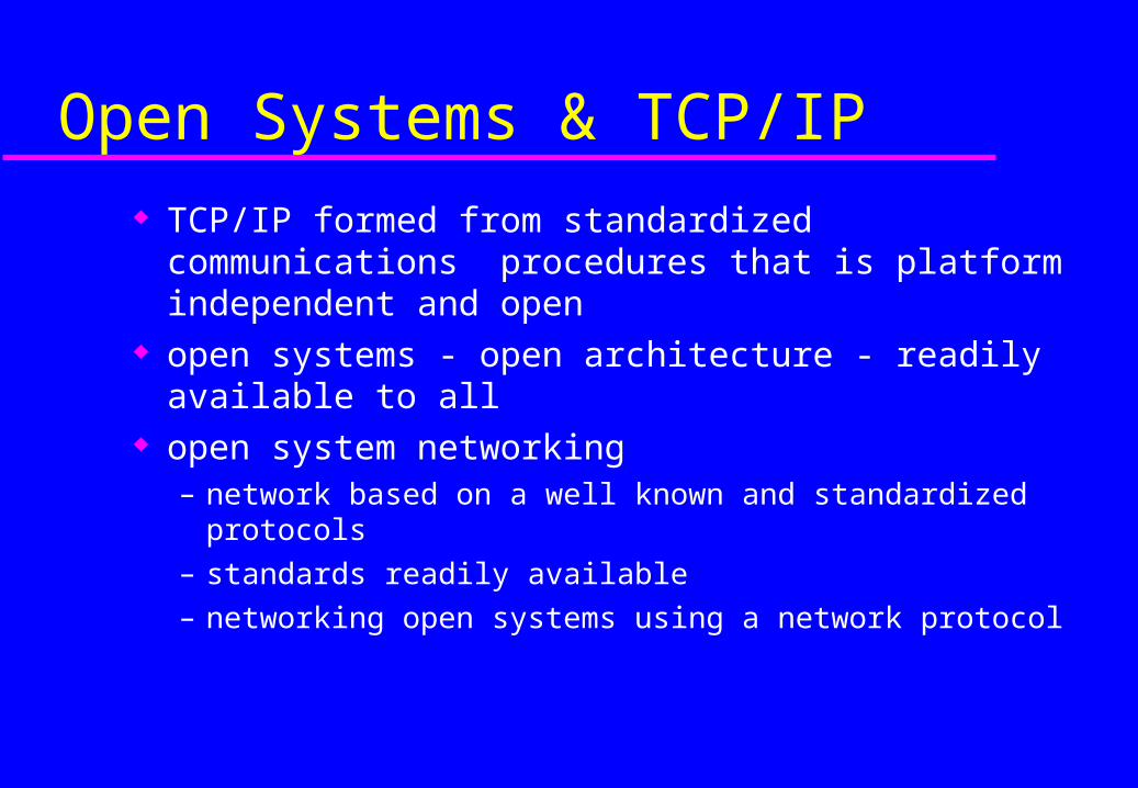
Open Systems & TCP/IP
TCP/IP formed from standardized communications procedures that is platform independent and open
open systems - open architecture - readily available to all
open system networking – network based on a well known and standardized protocols
– standards readily available
– networking open systems using a network protocol
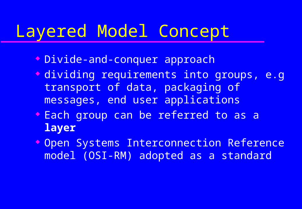
Layered Model Concept
Divide-and-conquer approach dividing requirements into groups, e.g transport
of data, packaging of messages, end user applications
Each group can be referred to as a layer Open Systems Interconnection Reference
model (OSI-RM) adopted as a standard

OSI Model
•Application oriented•Independent of layers below•Upper Layers
•Lower Layers•Transmission of data•don’t differentiate upper layers
1
3
2
4
5
6
7 Application
Presentation
Session
Transport
Network
Data Link
Physical
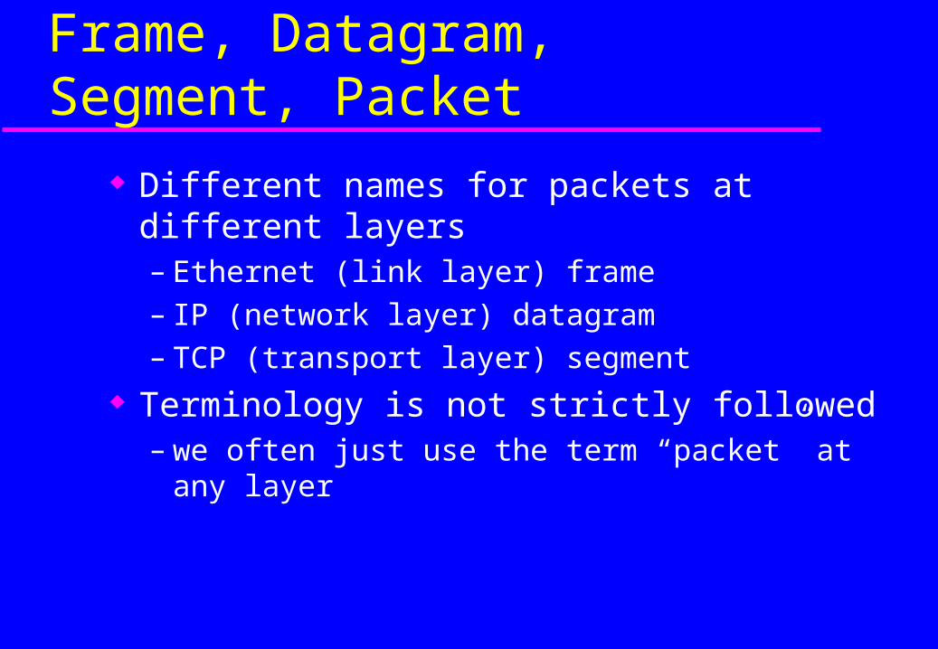
Frame, Datagram, Segment, Packet
Different names for packets at different layers– Ethernet (link layer) frame– IP (network layer) datagram– TCP (transport layer) segment
Terminology is not strictly followed– we often just use the term “packet” at any layer
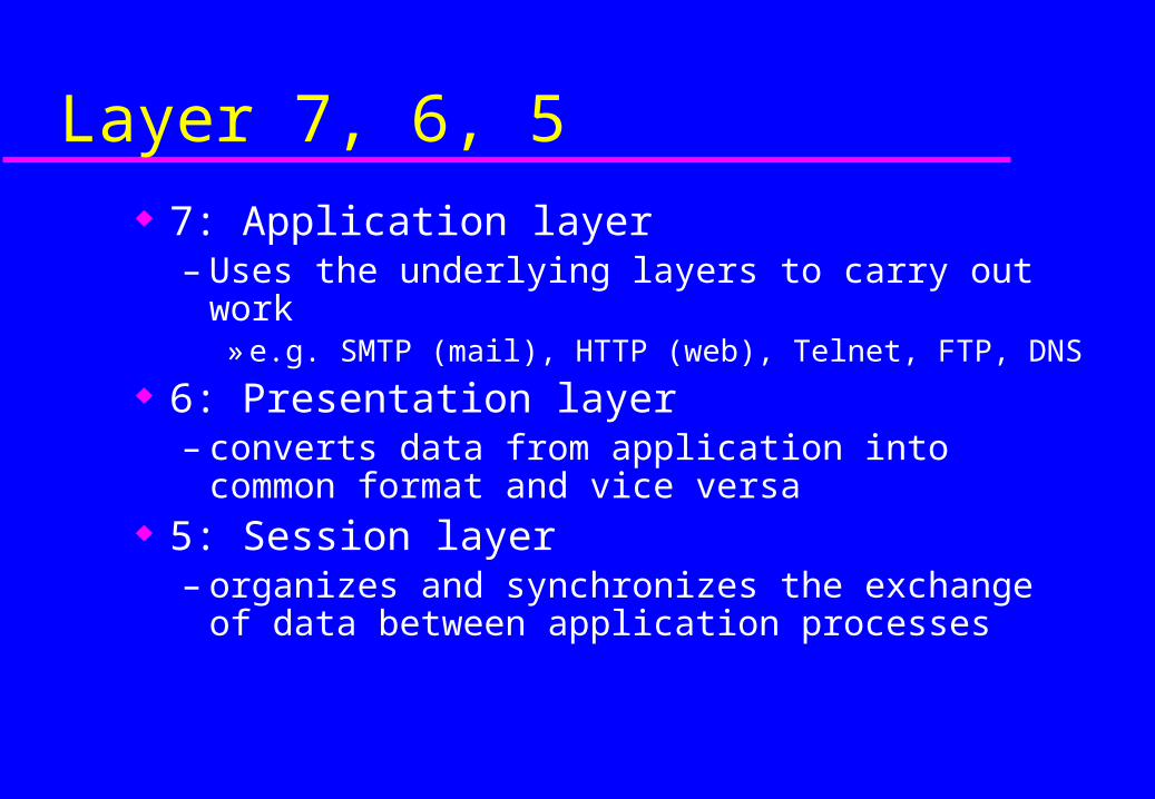
Layer 7, 6, 5 7: Application layer
– Uses the underlying layers to carry out work» e.g. SMTP (mail), HTTP (web), Telnet, FTP, DNS
6: Presentation layer– converts data from application into common format
and vice versa 5: Session layer
– organizes and synchronizes the exchange of data between application processes

Layer 4
4: Transport layer (e.g. TCP)– end to end transport of segments– encapsulates TCP segments in network layer packets– adds reliability by detecting and retransmitting lost
packets» uses acknowledgements and sequence numbers to keep
track of successful, out-of-order, and lost packets» timers help differentiate between loss and delay
UDP is much simpler: no reliability features

Layer 3
3: Network layer (e.g. IP)– Single address space for the entire internetwork– adds an additional layer of addressing
» e.g. IP address is distinct from MAC address)» so we need a way of mapping between different types of
addresses
– Unreliable (best effort)» if packet gets lost, network layer doesn’t care» higher layers can resend lost packets
Layer 3
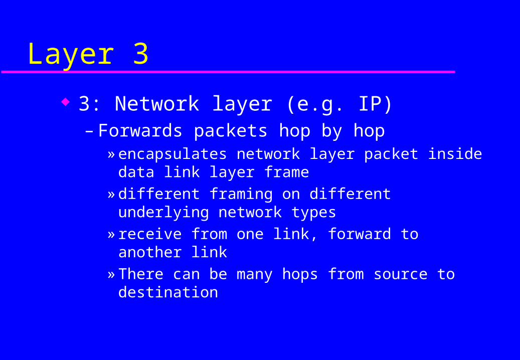
3: Network layer (e.g. IP)– Forwards packets hop by hop
» encapsulates network layer packet inside data link layer frame
» different framing on different underlying network types» receive from one link, forward to another link» There can be many hops from source to destination

Layer 3
3: Network layer (e.g. IP)– Makes routing decisions
» how can the packet be sent closer to its destination?» forwarding and routing tables embody “knowledge” of
network topology» routers can talk to each other to exchange information
about network topology

Layer 2
2: Data Link layer– bundles bits into frames and moves frames between
hosts on the same link– a frame has a definite start, end, size
» special delimiters to mark start and/or end
– often also a definite source and destination link-layer address (e.g. ethernet MAC address)
– some link layers detect corrupted frames– some link layers re-send corrupted frames (NOT
ethernet)
Layer 1
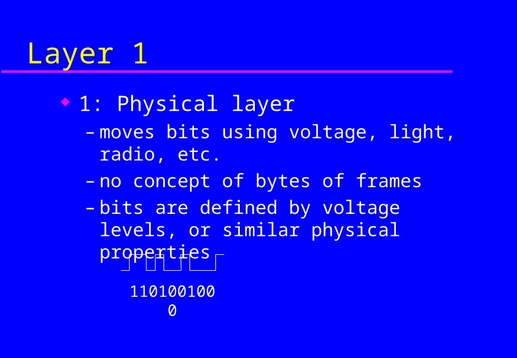
1: Physical layer– moves bits using voltage, light, radio, etc.– no concept of bytes of frames– bits are defined by voltage levels, or similar
physical properties
1101001000
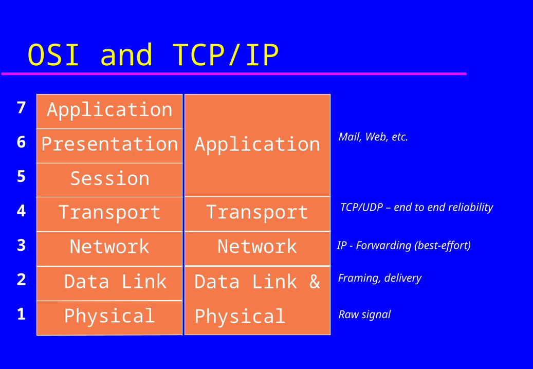
OSI and TCP/IP
TCP/UDP – end to end reliability
IP - Forwarding (best-effort)
Framing, delivery
Raw signal
Mail, Web, etc.
1
3
2
4
5
6
7 Application
Presentation
Session
Transport
Network
Data Link
Physical
Application
Transport
Network
Data Link &
Physical

Protocol Layers:The TCP/IP Hourglass Model
Network layer
Token Ring
ATM X.25 PPPFrame Relay
HDLCEthernet
IP
UDPTCP
HTTP FTP Telnet DNSSMTP Audio Video
RTP
Data link layer
Transport layer
Application layer
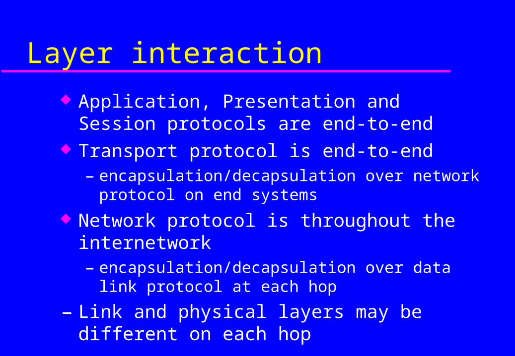
Layer interaction
Application, Presentation and Session protocols are end-to-end
Transport protocol is end-to-end– encapsulation/decapsulation over network protocol on end
systems
Network protocol is throughout the internetwork– encapsulation/decapsulation over data link protocol at each
hop
– Link and physical layers may be different on each hop
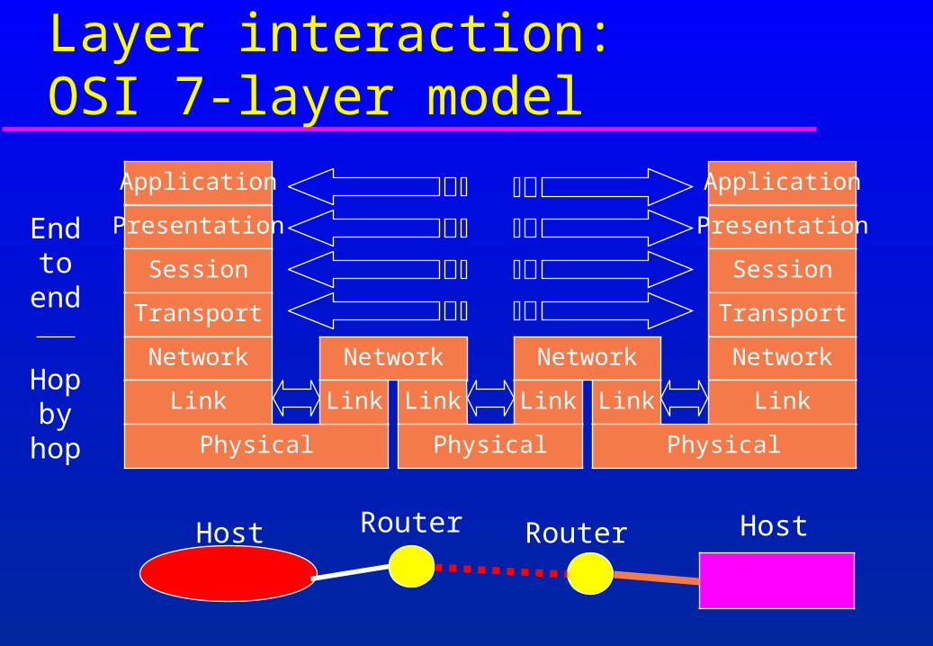
Layer interaction:OSI 7-layer model
Host Router Router Host
Application
Presentation
Session
Transport
Network
Link
Physical
Network
Link Link
Network
Link Link
Application
Presentation
Session
Transport
Network
Link
PhysicalPhysical
Hop by
hop
End to
end
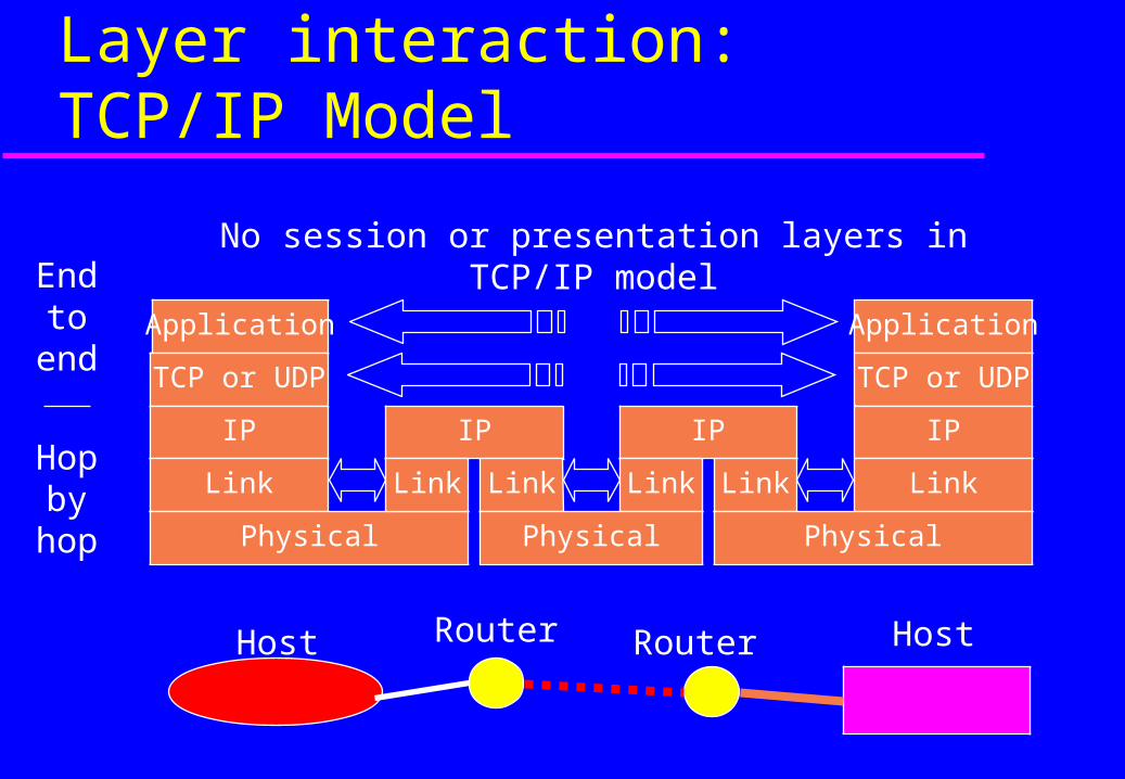
Layer interaction:TCP/IP Model
Host Router Router Host
Application
TCP or UDP
IP
Link
Physical
IP
Link Link
IP
Link Link
Application
TCP or UDP
IP
Link
PhysicalPhysical
Hop by
hop
End to
end
No session or presentation layers in TCP/IP model

Encapsulation & Decapsulation
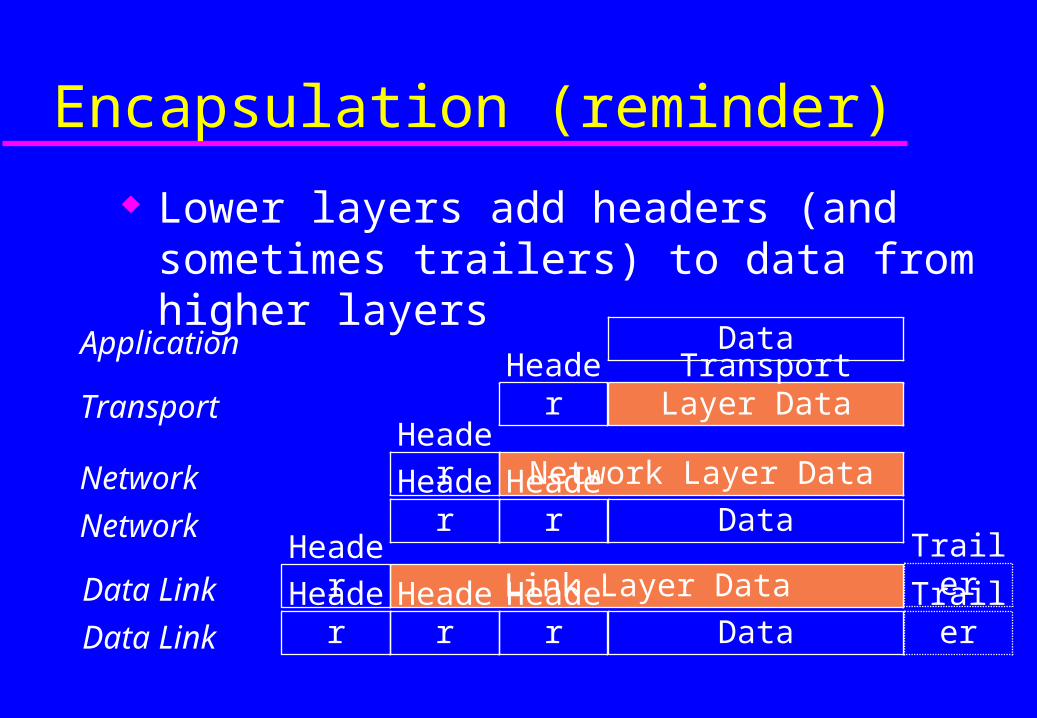
Lower layers add headers (and sometimes trailers) to data from higher layers
Application
Transport
Network
Data Link
Data Link
Network
Data
Transport Layer DataHeader
Network Layer DataHeader
DataHeaderHeader
Link Layer Data
DataHeaderHeader
Header
Header
Trailer
Trailer
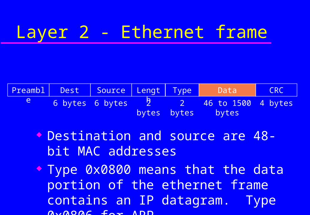
Destination and source are 48-bit MAC addresses
Type 0x0800 means that the data portion of the ethernet frame contains an IP datagram. Type 0x0806 for ARP.
Layer 2 - Ethernet frame
Preamble Dest
6 bytes
Source
6 bytes
Length
2 bytes
Data
46 to 1500 bytes
CRC
4 bytes
Type
2 bytes
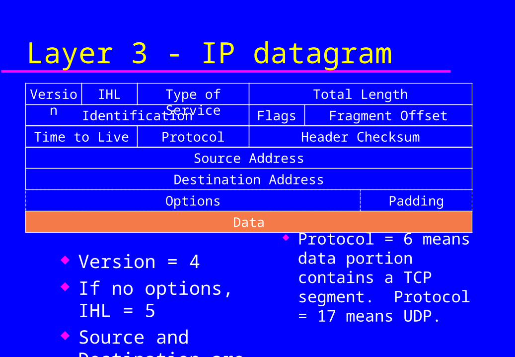
Protocol = 6 means data portion contains a TCP segment. Protocol = 17 means UDP.
Layer 3 - IP datagramIHL Type of Service Total LengthVersion
Fragment OffsetIdentification Flags
Time to Live Protocol Header Checksum
Source Address
Destination Address
Version = 4 If no options, IHL = 5 Source and Destination
are 32-bit IP addresses
Data
PaddingOptions
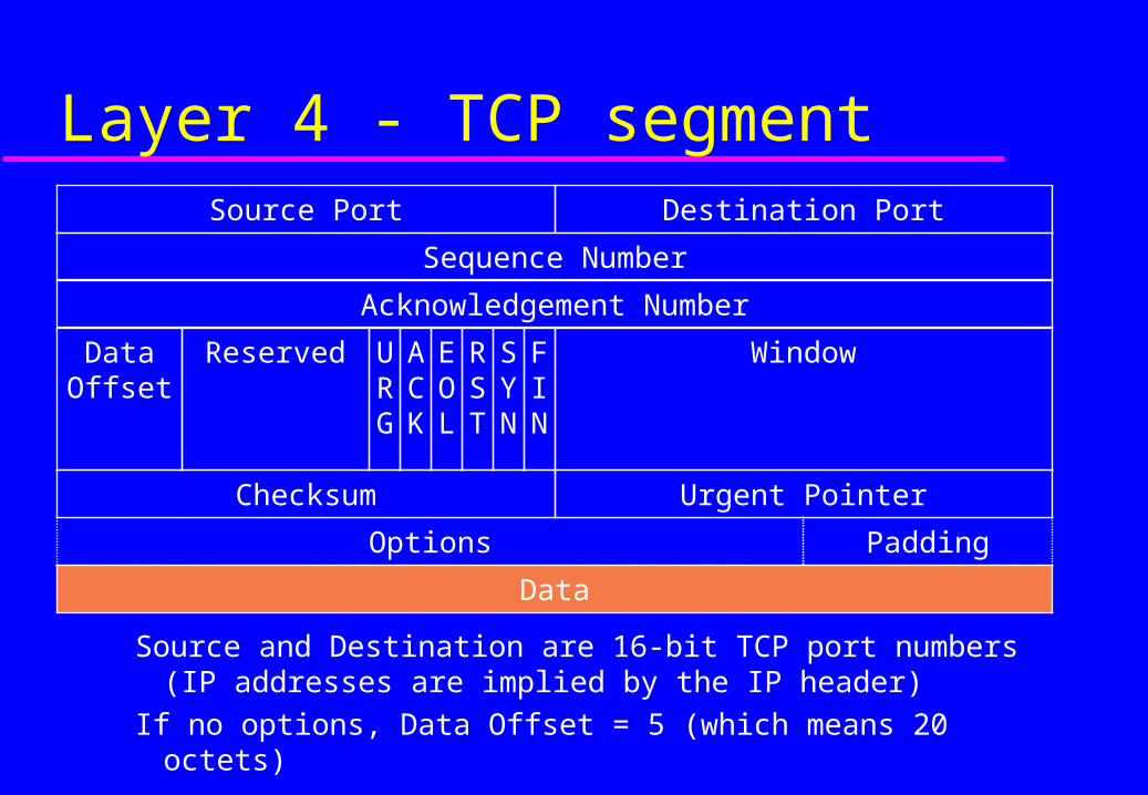
Source and Destination are 16-bit TCP port numbers (IP addresses are implied by the IP header)
If no options, Data Offset = 5 (which means 20 octets)
Layer 4 - TCP segmentSource Port Destination Port
Sequence Number
Acknowledgement Number
Data Offset
WindowReserved ACK
URG
EOL
RST
SYN
FIN
Checksum Urgent Pointer
Data
PaddingOptions
IP Addressing

Purpose of an IP address
Unique Identification of – Source
Sometimes used for security or policy-based filtering of data
– DestinationSo the networks know where to send the data
Network Independent Format– IP over anything
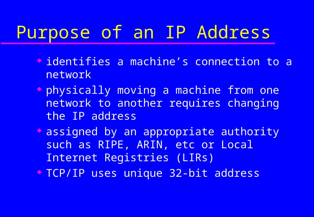
Purpose of an IP Address
identifies a machine’s connection to a network physically moving a machine from one network
to another requires changing the IP address assigned by an appropriate authority such as
RIPE, ARIN, etc or Local Internet Registries (LIRs)
TCP/IP uses unique 32-bit address
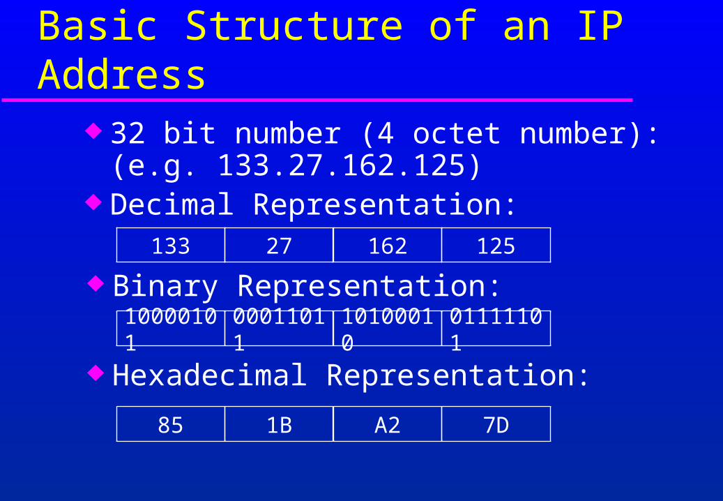
Basic Structure of an IP Address
133 27 162 125
10000101 00011011 10100010 01111101
85 1B A2 7D
32 bit number (4 octet number):(e.g. 133.27.162.125)
Decimal Representation:
Binary Representation:
Hexadecimal Representation:
A
C
B
FE
I
G
D
H
J
RouterPC
HUB
RouterPC
HUB
RouterPC
HUB
RouterPC
HUB
RouterPC
HUB
Router PC
HUB
Router PC
HUB
Router PC
HUB
Router PC
HUB
Router PC
HUB
SWITCH
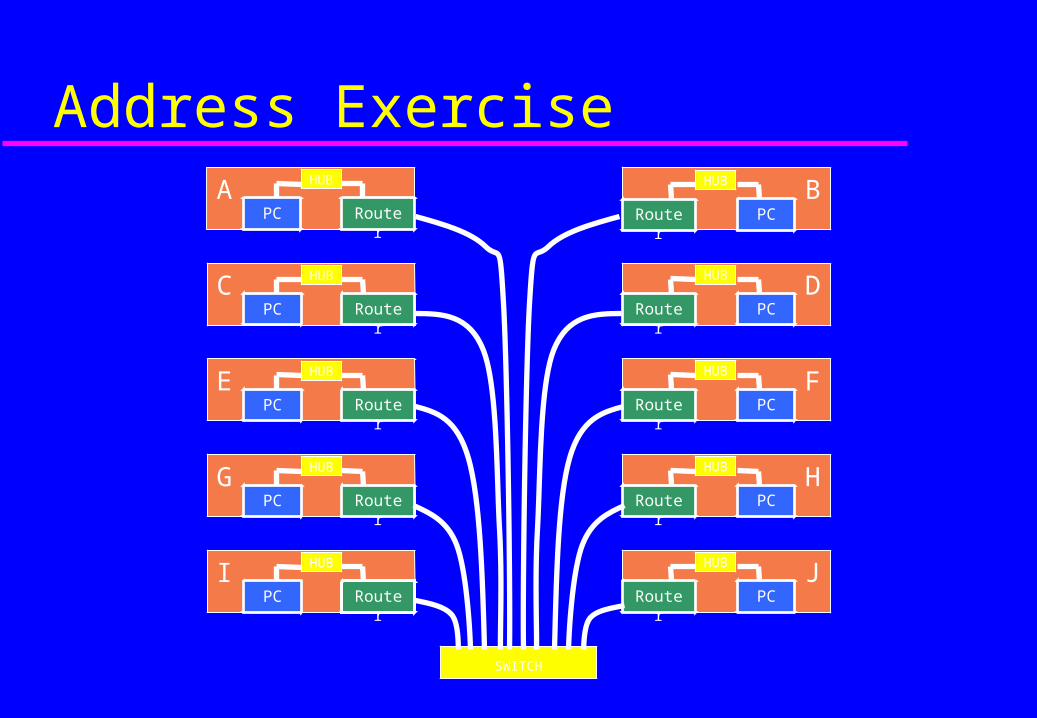
Address Exercise
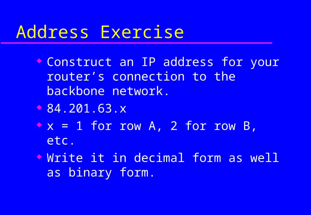
Address Exercise
Construct an IP address for your router’s connection to the backbone network.
84.201.63.x x = 1 for row A, 2 for row B, etc. Write it in decimal form as well as binary form.

Addressing in Internetworks
More than one physical network Different Locations Larger number of computers Need structure in IP addresses
– network part identifies which network in the internetwork (e.g. the Internet)
– host part identifies host on that network
Address Structure Revisited
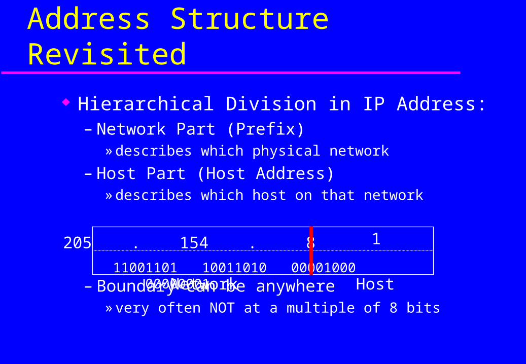
Hierarchical Division in IP Address:– Network Part (Prefix)
» describes which physical network
– Host Part (Host Address)» describes which host on that network
– Boundary can be anywhere» very often NOT at a multiple of 8 bits
Network Host
205 . 154 . 8 1
11001101 10011010 00001000 00000001

Network Masks Define which bits are used to describe the
Network Part and which for hosts Different Representations:
– decimal dot notation: 255.255.224.0– binary: 11111111 11111111 11100000 00000000
– hexadecimal: 0xFFFFE000– number of network bits: /19
Binary AND of 32 bit IP address with 32 bit netmask yields network part of address

137.158.128.0/17 (netmask 255.255.128.0)
Example Prefixes
1000 1001 1001 1110 1 000 0000 0000 0000
1111 1111 1111 1111 1 000 0000 0000 0000
1100 0110 1000 0110 0000 0000 0000 0000
1111 1111 1111 1111 0000 0000 0000 0000
1100 1101 0010 0101 1100 0001 10 00 0000
1111 1111 1111 1111 1111 1111 11 00 0000
198.134.0.0/16 (netmask 255.255.0.0)
205.37.193.128/26 (netmask 255.255.255.192)

Special Addresses
All 0’s in host part: Represents Network– e.g. 193.0.0.0/24– e.g. 138.37.128.0/17
All 1’s in host part:Broadcast– e.g. 137.156.255.255 (137.156.0.0/16)– e.g. 134.132.100.255 (134.132.100.0/24)– e.g. 190.0.127.255 (190.0.0.0/17)
127.0.0.0/8: Loopback address (127.0.0.1) 0.0.0.0: Various special purposes

Allocating IP Addresses
The subnet mask is used to define size of a network
E.g a subnet mask of 255.255.255.0 or /24 implies 32-24=8 host bits– 2^8 minus 2 = 254 possible hosts
Similarly a subnet mask of 255.255.255.224 or /27 implies 32-27=5 hosts bits– 2^5 minus 2 = 30 possible hosts
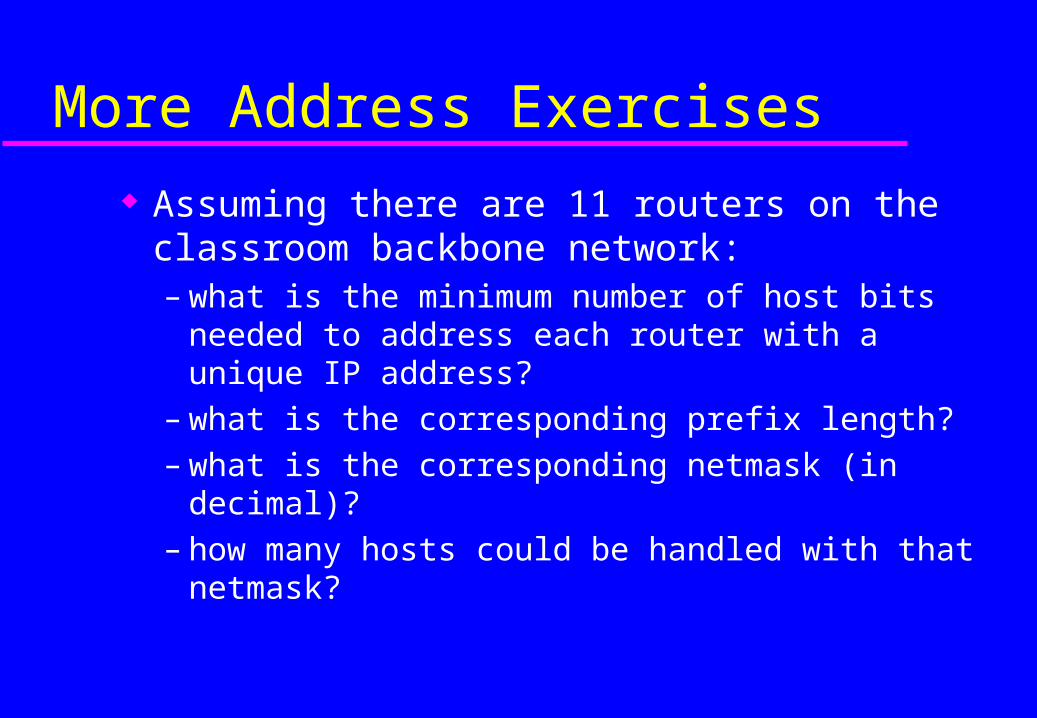
More Address Exercises
Assuming there are 11 routers on the classroom backbone network:– what is the minimum number of host bits needed to
address each router with a unique IP address?– what is the corresponding prefix length?– what is the corresponding netmask (in decimal)?– how many hosts could be handled with that
netmask?
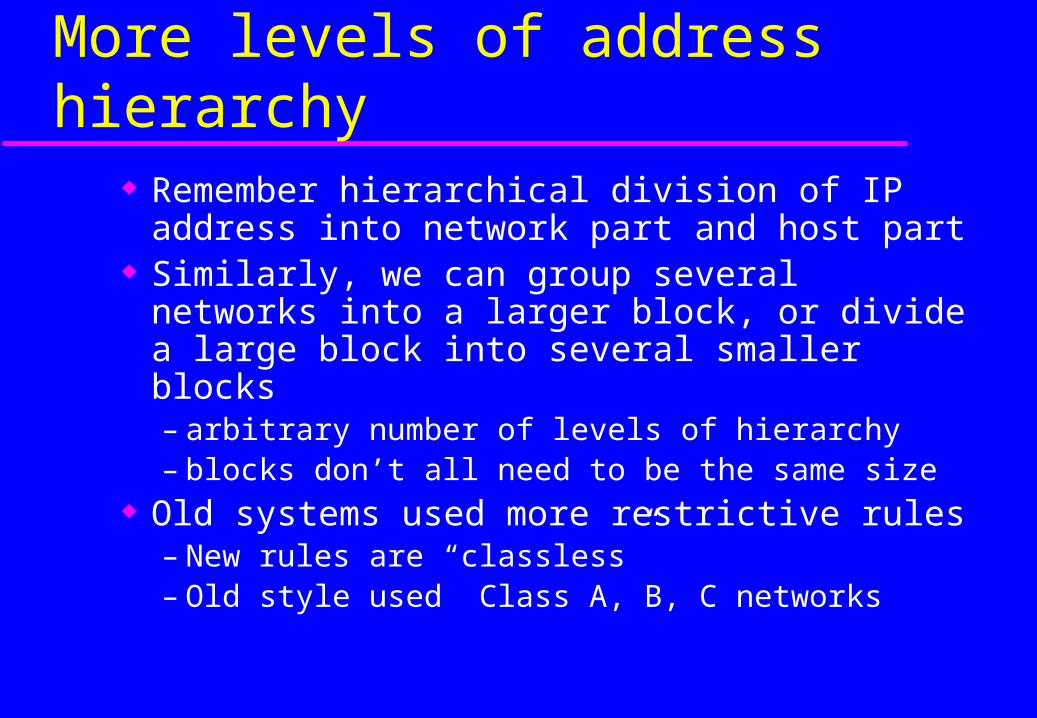
More levels of address hierarchy Remember hierarchical division of IP address
into network part and host part Similarly, we can group several networks into a
larger block, or divide a large block into several smaller blocks– arbitrary number of levels of hierarchy– blocks don’t all need to be the same size
Old systems used more restrictive rules– New rules are “classless”– Old style used Class A, B, C networks
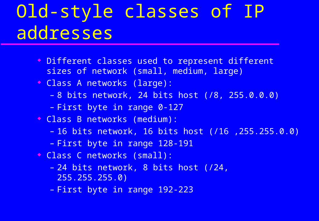
Old-style classes of IP addresses Different classes used to represent different sizes of network
(small, medium, large) Class A networks (large):
– 8 bits network, 24 bits host (/8, 255.0.0.0)– First byte in range 0-127
Class B networks (medium):– 16 bits network, 16 bits host (/16 ,255.255.0.0)– First byte in range 128-191
Class C networks (small):– 24 bits network, 8 bits host (/24, 255.255.255.0)– First byte in range 192-223

Old-style classes of IP addresses
Just look at the address to tell what class it is.– Class A: 0.0.0.0 to 127.255.255.255
» binary 0xxxxxxxxxxxxxxxxxxxxxxxxxxxxxxx
– Class B: 128.0.0.0 to 191.255.255.255» binary 10xxxxxxxxxxxxxxxxxxxxxxxxxxxxxx
– Class C: 192.0.0.0 to 223.255.255.255» binary 110xxxxxxxxxxxxxxxxxxxxxxxxxxxxx
– Class D: (multicast) 224.0.0.0 to 239.255.255.255» binary 1110xxxxxxxxxxxxxxxxxxxxxxxxxxxx
– Class E: (reserved) 240.0.0.0 to 255.255.255.255

Implied netmasks of classful addresses
A classful network has a “natural” or “implied” prefix length or netmask:– Class A: prefix length /8 (netmask 255.0.0.0)– Class B: prefix length /16 (netmask 255.255.0.0)– Class C: prefix length /24 (netmask 255.255.255.0)
Old routing systems often used implied netmasks Modern routing systems always use explicit
prefix lengths or netmasks
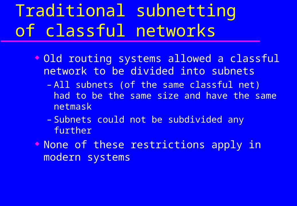
Traditional subnetting of classful networks
Old routing systems allowed a classful network to be divided into subnets– All subnets (of the same classful net) had to be the
same size and have the same netmask– Subnets could not be subdivided any further
None of these restrictions apply in modern systems

Traditional supernetting
Some traditional routing systems allowed supernets to be formed by combining adjacent classful nets.– e.g. combine two Class C networks (with
consecutive numbers) into a supernet with netmask 255.255.254.0
Modern systems use more general classless mechanisms.
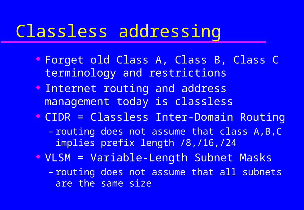
Classless addressing
Forget old Class A, Class B, Class C terminology and restrictions
Internet routing and address management today is classless
CIDR = Classless Inter-Domain Routing– routing does not assume that class A,B,C implies
prefix length /8,/16,/24 VLSM = Variable-Length Subnet Masks
– routing does not assume that all subnets are the same size
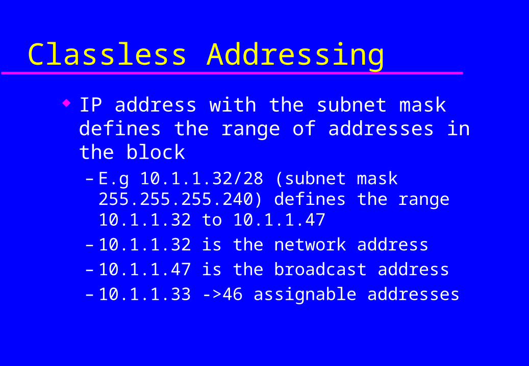
Classless Addressing
IP address with the subnet mask defines the range of addresses in the block– E.g 10.1.1.32/28 (subnet mask 255.255.255.240)
defines the range 10.1.1.32 to 10.1.1.47– 10.1.1.32 is the network address– 10.1.1.47 is the broadcast address– 10.1.1.33 ->46 assignable addresses
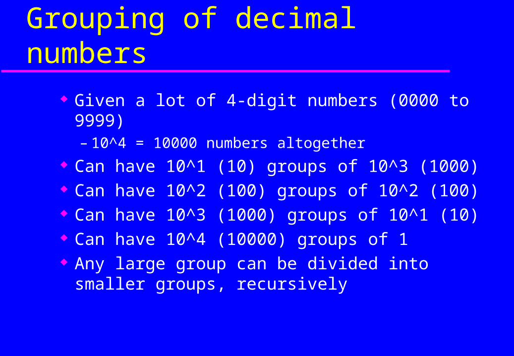
Grouping of decimal numbers
Given a lot of 4-digit numbers (0000 to 9999)– 10^4 = 10000 numbers altogether
Can have 10^1 (10) groups of 10^3 (1000) Can have 10^2 (100) groups of 10^2 (100) Can have 10^3 (1000) groups of 10^1 (10) Can have 10^4 (10000) groups of 1 Any large group can be divided into smaller
groups, recursively
Grouping of binary numbers
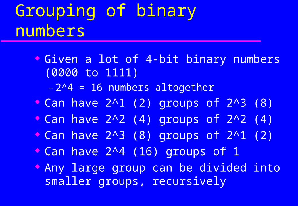
Given a lot of 4-bit binary numbers (0000 to 1111)– 2^4 = 16 numbers altogether
Can have 2^1 (2) groups of 2^3 (8) Can have 2^2 (4) groups of 2^2 (4) Can have 2^3 (8) groups of 2^1 (2) Can have 2^4 (16) groups of 1 Any large group can be divided into smaller
groups, recursively
Grouping of binary numbers
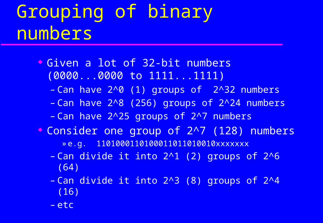
Given a lot of 32-bit numbers (0000...0000 to 1111...1111)– Can have 2^0 (1) groups of 2^32 numbers– Can have 2^8 (256) groups of 2^24 numbers– Can have 2^25 groups of 2^7 numbers
Consider one group of 2^7 (128) numbers» e.g. 1101000110100011011010010xxxxxxx
– Can divide it into 2^1 (2) groups of 2^6 (64)– Can divide it into 2^3 (8) groups of 2^4 (16)– etc
Classless addressing example
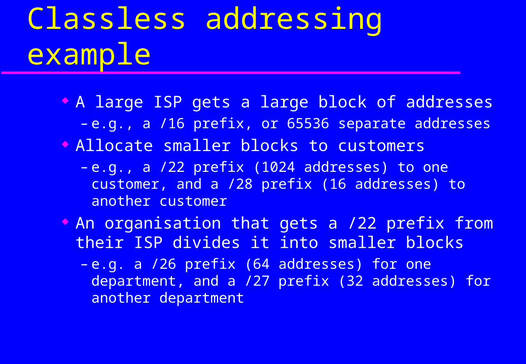
A large ISP gets a large block of addresses– e.g., a /16 prefix, or 65536 separate addresses
Allocate smaller blocks to customers– e.g., a /22 prefix (1024 addresses) to one customer,
and a /28 prefix (16 addresses) to another customer An organisation that gets a /22 prefix from their
ISP divides it into smaller blocks– e.g. a /26 prefix (64 addresses) for one department,
and a /27 prefix (32 addresses) for another department
Classless addressing exercise
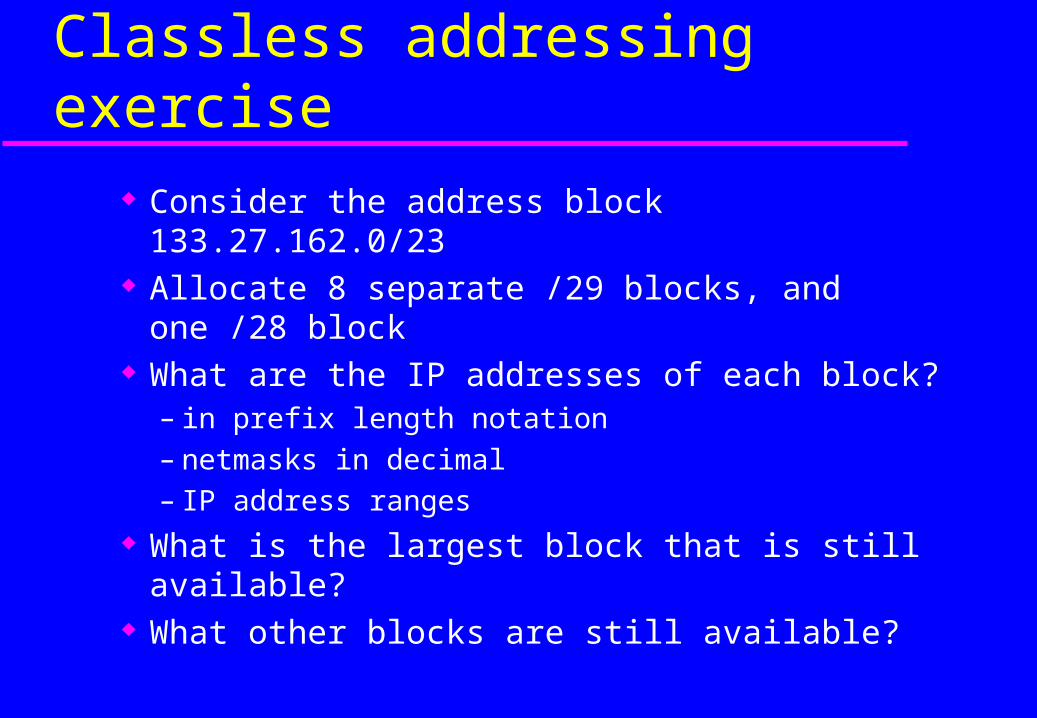
Consider the address block 133.27.162.0/23 Allocate 8 separate /29 blocks, and one /28 block What are the IP addresses of each block?
– in prefix length notation– netmasks in decimal– IP address ranges
What is the largest block that is still available? What other blocks are still available?

Large Network Issues & Routers

Large Networks
As networks grow larger it becomes necessary to split them into smaller networks that are interconnected
Since each network needs to be connected to every other network, the number of links can be quite high: N (N-1)/2
4 LANs would require six links!

WAN Design
Goal: To minimize the number of interconnecting links
Removing the direct links means that a mechanism must move data packets from their source, through other intermediate nodes and on to the final destination.
This function is performed by a Router
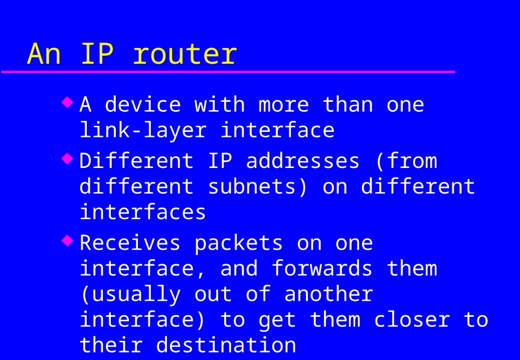
An IP router
A device with more than one link-layer interface
Different IP addresses (from different subnets) on different interfaces
Receives packets on one interface, and forwards them (usually out of another interface) to get them closer to their destination
Maintains forwarding tables

IP router - action for each packet
Packet is received on one interface Check whether the destination address is the
router itself Decrement TTL (time to live), and discard
packet if it reaches zero Look up the destination IP address in the
forwarding table Destination could be on a directly attached link,
or through another router
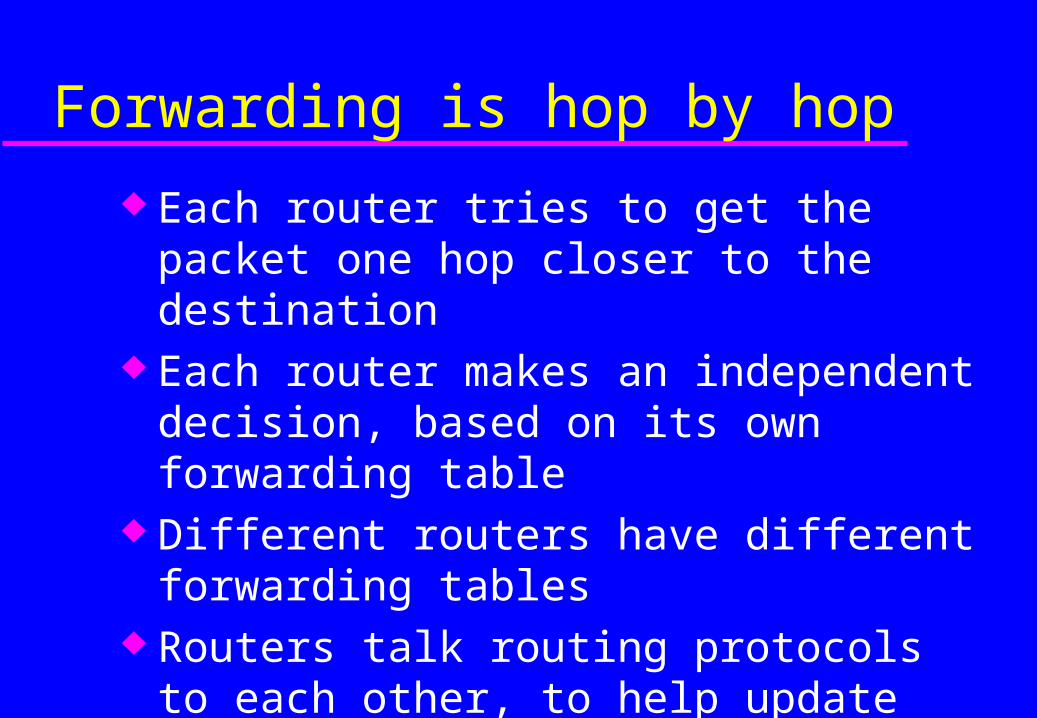
Forwarding is hop by hop
Each router tries to get the packet one hop closer to the destination
Each router makes an independent decision, based on its own forwarding table
Different routers have different forwarding tables
Routers talk routing protocols to each other, to help update routing and forwarding tables
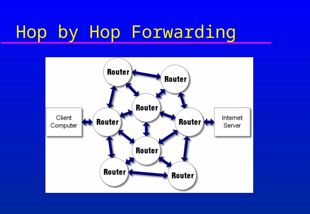
Hop by Hop Forwarding

Router Functions Determine optimum routing paths through a network
» Lowest delay» Highest reliability
Transport packets through the network» Examines destination address in packet» Makes a decision on which port to forward the packet through» Decision is based on the Routing Table
Interconnected Routers exchange routing tables in order to maintain a clear picture of the network
In a large network, the routing table updates can consume a lot of bandwidth
» a protocol for route updates is required

Forwarding table structure
We don't list every IP number on the Internet - the table would be huge
Instead, the forwarding table contains prefixes (network numbers)
– "If the first /n bits matches this entry, send the datagram this way"
If more than one prefix matches, the longest prefix wins (more specific route)
0.0.0.0/0 is "default route" - matches anything, but only if no other prefix matches
Encapsulation and Types of Links
Encapsulation (reminder)
Lower layers add headers (and sometimes trailers) to data from higher layers
Application
Transport
Network
Data Link
Data Link
Network
Data
Transport Layer DataHeader
Network Layer DataHeader
DataHeaderHeader
Link Layer Data
DataHeaderHeader
Header
Header
Trailer
Trailer

Classes of links
Different strategies for encapsulation and delivery of IP packets over different classes of links
Point to point (e.g. PPP) Broadcast (e.g. Ethernet) Non-broadcast multi-access (e.g. Frame Relay,
ATM)

Point to point links
Two hosts connected by a point-to-point link– data sent by one host is received by the other
Sender takes IP datagram, encapsulates it in some way (PPP, SLIP, HDLC, ...), and sends it
Receiver removes link layer encapsulation Check integrity, discard bad packets, process
good packets

Broadcast links
Many hosts connected to a broadcast medium– Data sent by one host can be received by all other
hosts– example: radio, ethernet

Broadcast links
Protect against interference from simultaneous transmissions interfering
Address individual hosts– so hosts know what packets to process and which to
ignore– link layer address is very different from network layer
address Mapping between network and link address (e.g.
ARP)
NBMA links (Non-broadcast multi-access)
e.g. X.25, Frame Relay, SMDS Many hosts Each host has a different link layer address Each host can potentially send a packet to any
other host Each packet is typically received by only one
host Broadcast might be available in some cases

ARP
Ethernet Essentials
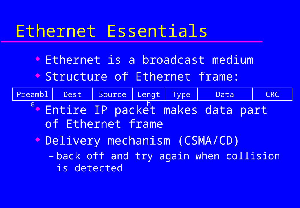
Ethernet is a broadcast medium Structure of Ethernet frame:
Entire IP packet makes data part of Ethernet frame
Delivery mechanism (CSMA/CD)– back off and try again when collision is detected
Preamble Dest Source Length Data CRCType
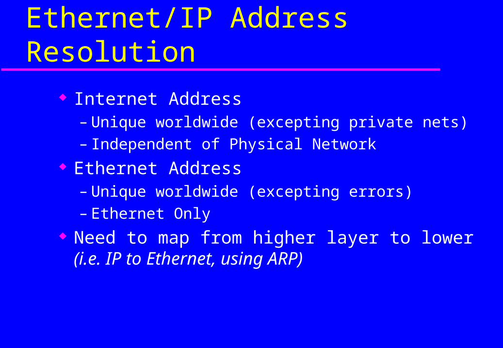
Ethernet/IP Address Resolution
Internet Address– Unique worldwide (excepting private nets)– Independent of Physical Network
Ethernet Address– Unique worldwide (excepting errors)– Ethernet Only
Need to map from higher layer to lower(i.e. IP to Ethernet, using ARP)
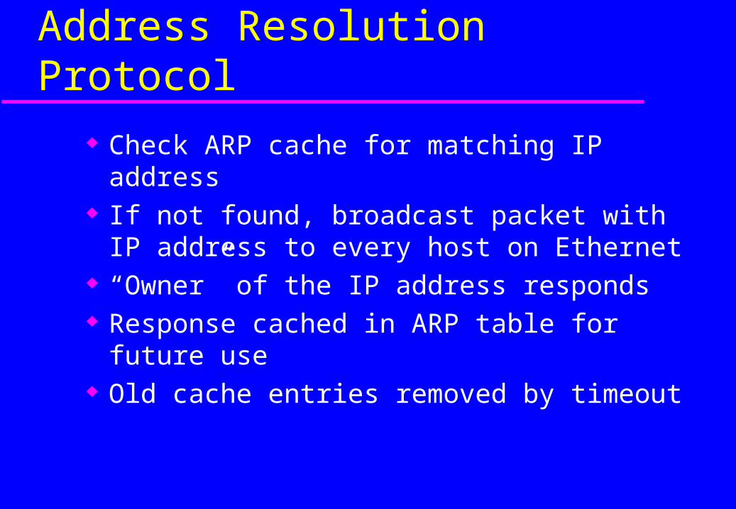
Address Resolution Protocol
Check ARP cache for matching IP address If not found, broadcast packet with IP address
to every host on Ethernet “Owner” of the IP address responds Response cached in ARP table for future use Old cache entries removed by timeout
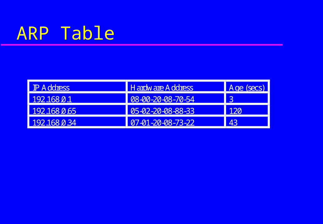
ARP Table
IP Address Hardware Address Age (secs)
192.168.0.1 08-00-20-08-70-54 3
192.168.0.65 05-02-20-08-88-33 120
192.168.0.34 07-01-20-08-73-22 43
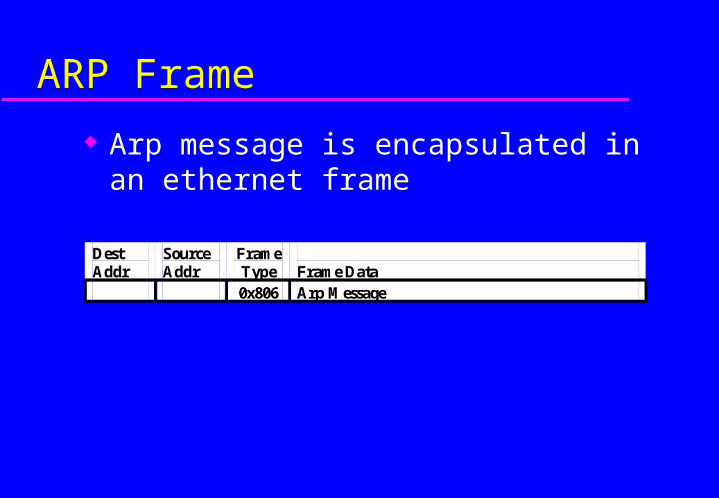
ARP Frame
Arp message is encapsulated in an ethernet frame
Dest Addr
Source Addr
Frame Type
Frame Data
0x806 Arp Message

Format of an ARP Message
0 8 16 31Hardware Type Protocol Type
HLEN PLEN Operation
Sender HA
Sender HA Sender IP Addr
Sender IP Add Target HA
Target HA
Target IP
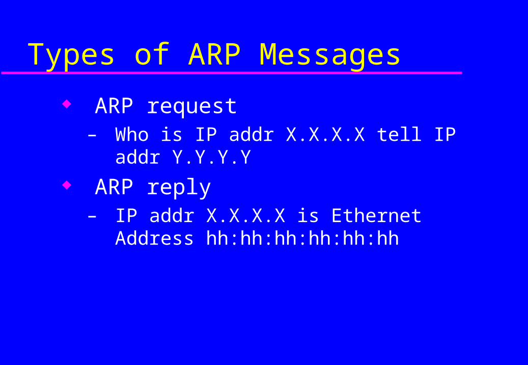
Types of ARP Messages
ARP request – Who is IP addr X.X.X.X tell IP addr Y.Y.Y.Y
ARP reply – IP addr X.X.X.X is Ethernet Address
hh:hh:hh:hh:hh:hh
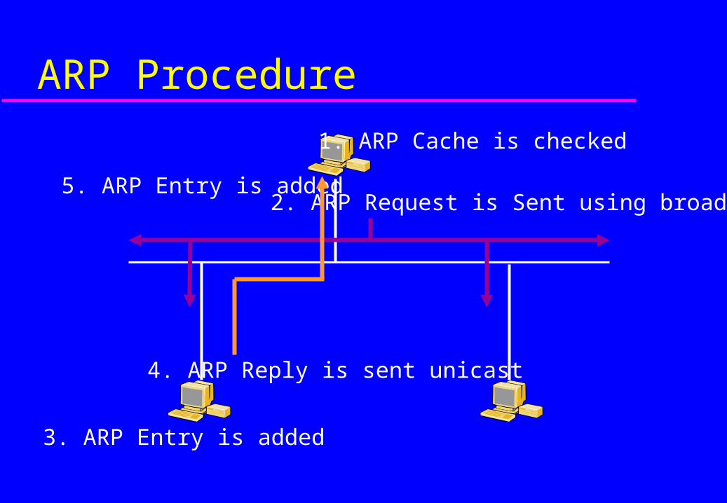
ARP Procedure
1. ARP Cache is checked
2. ARP Request is Sent using broadcast
3. ARP Entry is added
4. ARP Reply is sent unicast
5. ARP Entry is added
Reverse ARP - RARP
For host machines that don't know their IP address – e.g diskless systems
RARP enables them to request their IP address from the gateway's ARP cache
Need an RARP server See RFC 903 NOTE: This is not used much nowadays
– DHCP does same function