IP Tagore Issue - Final(1861-1941) Editor Navdeep Suri Guest Editor

IP-2000 Master Station Scantasks
over IP Editor and Operations Manual
TDMS-Plus Master Station Software December 2018

TDMS-Plus Master Station IP-2000 Software Scantasks over IP
Copyright © 2016 by QEI IP-2000 Master Station Scantasks over IP Editor and Operations Manual ALL RIGHTS RESERVED
NOTICE
The information in this document has been carefully checked and is believed to be accurate. However, no responsibility is assumed or implied for inaccuracies. Further more, QEI reserves the right to make changes to any products herein described to improve reliability, function or design. QEI does not assume liability arising to the application or use of any product or circuit described herein; neither does it convey any license under its patent rights nor the rights of others.
This manual and all data contained constitutes proprietary information of QEI and shall not be reproduced, copied or disclosed to others, or used as the basis for manufacture without written consent of QEI.
45 Fadem Road Springfield, NJ 07081 Phone: (973) 379-7400 Fax: (973) 379-2138 Web Site: www.qeiinccom

TDMS-Plus Master Station IP-2000 Software Scantasks over IP
Copyright © 2016 QEI Revisions i
Revisions
Revision Description Date
A Released to Production June 2002
B Revised Pg. 1 Introduction & Pg. 2 (2.1) Installation January 2003
C Title Change to TDMS-Plus December 2004
D Revised INPMAP, added Details, IP-based Serial Configuration
November 2006
E Support names and TCP/IP addresses January 2008
F Add BRC and STM transport modes November 2009
G Corrected name_service instructions November 2010
H Remove port restrictions; Added new listen functionality
March 2012
I Formatting Update August 2013
J Formatting Update April 2016
K Updated QEI Address December 2018

TDMS-Plus Master Station IP-2000 Software Scantasks over IP
Copyright © 2016 QEI Contents i
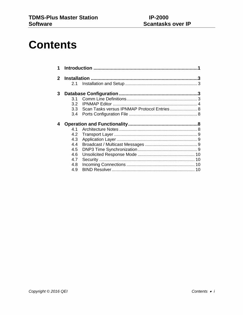
Contents
1 Introduction ..............................................................................1
2 Installation ................................................................................3 2.1 Installation and Setup .......................................................... 3
3 Database Configuration ...........................................................3 3.1 Comm Line Definitions ......................................................... 3 3.2 IPNMAP Editor .................................................................... 4 3.3 Scan Tasks versus IPNMAP Protocol Entries ...................... 8 3.4 Ports Configuration File ....................................................... 8
4 Operation and Functionality ....................................................8 4.1 Architecture Notes ............................................................... 8 4.2 Transport Layer ................................................................... 9 4.3 Application Layer ................................................................. 9 4.4 Broadcast / Multicast Messages .......................................... 9 4.5 DNP3 Time Synchronization ................................................ 9 4.6 Unsolicited Response Mode .............................................. 10 4.7 Security ............................................................................. 10 4.8 Incoming Connections ....................................................... 10 4.9 BIND Resolver ................................................................... 10


TDMS-Plus Master Station IP-2000 Software Scantasks over IP
Copyright © 2016 QEI Introduction 1
1 Introduction
The QEI Scan Task IP Network Interface enables standard TDMS-Plus Master Station Scan Tasks to communicate to remote devices using TCP/IP.
The QEI Scan Task IP Network Interface consists of two basic parts, the TCP Switch process and the IPNMAP Editor Screen.
The TCP Switch process creates a number of IP terminal devices named IPN”nn” which the Scan Tasks connect to. It routes requests and responses between the Scan Tasks and remote IP-enabled RTU’s or IED’s. A routing table is created using the IPNMAP Editor Screen which specifies the remote IP addresses or names of the Commlines/RTU’s/IED’s.
Connections can be configured to be UDP or TCP. The TCP Switch process maintains TCP connections to all Commlines/RTU’s in the mapping table which are configured for TCP mode. In addition, the TCP Switch process can be configured to listen for incoming TCP connection requests from remote Commlines/RTU’s/IED’s. Broadcasts are sent as multiple individual packets to all mapped RTU’s on the commline. Entire commlines attached to a single TCP/IP terminal server port can be defined. These commlines can be configured for redundant connections as well.
At present the DNP, QUICS, LGYR and MODBUS protocols are supported. The TCP Switch process listens on port 20000 for DNP connection requests, on port 20001 for QUICS connection requests, on port 20002 for LGYR connection requests and on port 502 for MODBUS connection requests.
In addition, the user can define devices on specific TCP/IP ports (specified in the Protocol entry) using a connection device in IPNMAP. These entries should contain 0 for the RTU number. The TCP Switch will also listen on these user-defined ports for incoming connections. These devices are designed for entire communication lines on a network-based terminal server.
In addition, the user can specify listening connections for specific TCP ports. These connections can specify specific TCP/IP addresses or can be configured to accept connection from any TCP/IP address.
The TCP Switch process generates a log file (MG:[SCADA]TCPSW.LOG) which logs information about the connection status of the TCP/IP connections. To obtain more detailed logging information, run the TCP Switch process interactively under the process name “MONITOR” – the source, destination and packet size of each packet routed through the TCP Switch will be logged.
Up to 5376 connections can be entered in the IPNMAP Editor.
The maximum number of TCP connections is limited by the hardware – it is in the region of 100 – 200 connections. This number can be increased to some extent by system tuning i.e. modifying quotas.
This manual is organized in the following sections:
Section 2 Installation
Section 3 Configuration
Section 4 Operation and Functionality Notes

TDMS-Plus Master Station IP-2000 Software Scantasks over IP
2 Introduction Copyright © 2016 QEI
NOTE: Please read the entire manual prior to attempting any installation and configuration.

TDMS-Plus Master Station IP-2000 Software Scantasks over IP
Copyright © 2016 QEI Installation 3
2 Installation
There are two steps to be performed in order to install the software for the IP Scantask support. The following steps assume the installer/operator has some prior knowledge of the OpenVMS operating system and of the structure and implementation of QEI’s TDMS-Plus database. For more information on these topics, please refer to QEI’s SM-2000 (TDMS-Plus System Manager’s Guide) and DB-2000 (TDMS-Plus Database Preparation).
2.1 Installation and Setup
Repeat the following steps on the A and B (if present) machines:
Add the following section to OPTTSK.COM
$! ----> Install IP Network Interface
$!
$ @MG:[IPNET.INSTALL]IPNTSK
$!
Add the following entry to the USERED screen:
IPNMAP S 002 IP NETWORK INTERFACE MAPPING TABLE
Create the database file SPARE_176.DAT and size it to 256 records:
HOSTA>set def mg:[DATABASE]
HOSTA>filcrt creat/size=256 176
WARNING: Care must be exercised when creating and sizing files. Please consult QEI Customer Service if assistance is required.
3 Database Configuration
There are only two steps required to configure a communication line to be IP enabled. The first is to set the commline (communication device) in CONFIG.X and the second is to define an IP mapping entry for each IP enabled RTU’s on the commline or for the entire commline.
3.1 Comm Line Definitions
For each communication line to be configured for IP communications, add a line in the CONFIG.X (where is X is for A or B, depending on which machine) similar to the following:
$ COMLINxx :== IPNyy:
where xx defines the comm. line number and yy defines the IPNMAP device number.
After these changes are made, the system must be rebooted for the changes to take effect.

TDMS-Plus Master Station IP-2000 Software Scantasks over IP
4 Database Configuration Copyright © 2016 QEI
3.2 IPNMAP Editor
At this point, the database is ready to configured to map Commlines/RTU’s to IP addresses. Via the IPNMAP editor screen, each RTU on each IP enabled commline is mapped to a remote IP address or the entire commline can be mapped to a remote IP address and port. The IP transport protocol to be used and the communication protocol of the commline are also specified for each RTU. For entire commlines attached to a single terminal server port, use an RTU address of 0 and specify the TCP/IP port number in the protocol field. Table 3.2 shows the valid entries for these fields and Figure 3.2 is the IPNMAP editor with some valid entries for an example of what an actual entry might look like.
Field Attribute Valid Range
Device Number 0 – 99
RTU Number 0 – 65535 *
Address Any valid IP address or host name
Transport TCP, UDP, BRC, or STM (outbound). LNT or LNU (listening)
Port DNP, QUICS, MODBUS, LGYR, DNPALT, or Port #
Protocol SCADA protocol – only required for ports not using pre-defined port names (above) – choices are Q(UICS), D(NP), M(ODBUS), or L(GYR).
Table 3.2 IPNMAP Fields and Valid Ranges
NOTE: The RTU Address is dependent on which protocol is assigned. QUICS can only handle a maximum address of 127. DNP can handle a maximum address of 4096. Use RTU Address of 0 for entire commline on a single TCP/IP address and port.
NOTE: STM and BRC transports use TCP as the base transport. STM is for those applications that require the data be returned to the application prior to the request for the data (AYDIN). BRC is for those applications that require broadcast of packets to all connected devices on the network for a particular device (Softmux).

TDMS-Plus Master Station IP-2000 Software Scantasks over IP
Copyright © 2016 QEI Database Configuration 5

TDMS-Plus Master Station IP-2000 Software Scantasks over IP
6 Database Configuration Copyright © 2016 QEI
Figure 3.2 IPNMAP Editor

TDMS-Plus Master Station IP-2000 Software Scantasks over IP
Copyright © 2016 QEI Database Configuration 7
Figure 3.3 IP Network Mapping screen (Plus Editors)

TDMS-Plus Master Station IP-2000 Software Scantasks over IP
8 Operation and Functionality Copyright © 2016 QEI
3.3 Scan Tasks versus IPNMAP Protocol Entries
Each Port/Protocol Entry has an associated Scan Task (and Scan Task Configuration Manual)
The scan tasks associated with the protocols are:
Scan Task Name Port Protocol
QUICS QUICS Q
DNP DNP D
MODBUS MODBUS M
Landis&Gyr LGYR L
Any Port Number Q, D, M, L or <none>
3.4 Ports Configuration File
Edit the file MG:[IPNET.INSTALL]PORTS.CFG
to match the following if needed:
#
# Protocol: Port:
#
DNP 20000
QUICS 20001
MODBUS 502
DNPALT 20003
LGYR 20002
4 Operation and Functionality
4.1 Architecture Notes
A basic idea of the structure and mechanism is given to provide some insight as to how the Scantasks operate over IP.

TDMS-Plus Master Station IP-2000 Software Scantasks over IP
Copyright © 2016 QEI Operation and Functionality 9
TCP connections can be initiated either by the Master Station of the RTU. The TCP Switch process will continually try to connect to all unconnected RTU’s in the Mapping Table. If the TCP Switch process receives a connection from an RTU, the TCP Switch process will mark that RTU as connected and close any other existing connections to that RTU.
Each SCADA protocol has a pre-defined well known port address for accepting TCP connections and for all UDP data communications. DNP has a port number of 20000, which has been registered with IANA (Internet Assigned Numbers Authority) and the DNP3 User’s Group. For QUICS, the assigned port is 20001.
The TCP Switch process supports look-up of host names to TCP/IP addresses. The user entry in IPNMAP will contain a fully-qualified host name (including domain name). The TCP Switch will periodically re-resolve the host name to TCP/IP address. This functionality supports local host names and DNS resolution via the BIND resolver.
4.2 Transport Layer
The IP Network Interface supports both UDP and TCP communications. Below are some comments to keep in mind:
UDP should not be used over a mesh topology WAN because of the possibility of receiving out-of-order or duplicate packets.
UDP can be used on high-reliability single-segment LAN’s and on high reliability non-mesh WAN’s
UDP is more economical than TCP over a pay-per-byte connection such as CDPD (Cellular Digital Packet Data) network.
TCP should be used over a mesh topology WAN.
4.3 Application Layer
The application layer (scantask) is responsible for determining the online status of each RTU, utilizing standard available procedures within the particular SCADA protocol. The scantasks will not rely on the connection status of the transport layer to determine online status of the RTU.
4.4 Broadcast / Multicast Messages
SCADA protocol broadcasts are sent as multiple individual IP packets to all mapped RTU’s on the commline.
4.5 DNP3 Time Synchronization
Due to variable delays in an IP network, RTU’s should not rely on the Master for time synchronization. An external time source such as GPS should be used.

TDMS-Plus Master Station IP-2000 Software Scantasks over IP
10 Operation and Functionality Copyright © 2016 QEI
4.6 Unsolicited Response Mode
When operating over IP there is no need for the Master station to control channel access via polling. If supported by the SCADA protocol, it would be more efficient for the RTU to send unsolicited data to the Master, with the occasional full data poll by the master to ensure database synchronization. DNP3 supports unsolicited responses.
4.7 Security
The TDMS-Plus IP Network Interface accepts TCP connections and receives UDP data grams from hosts that are defined in the Mapping Table.
RTU’s should be configured to accept connections from (or attempt to connect to) either of two IP addresses in a dual system and only one IP address in a single computer system.
4.8 Incoming Connections
The TDMS-Plus IP Network Interface accepts incoming connections that are defined in the Mapping Table.
The user should configure acceptable inbound connections using the LNT (TCP transport) or LNU (UDP transport) keywords in the Transport field. For restrictions to a specific TCP/IP address, enter it in the Address field. To accept connections from any TCP/IP address, leave the Address field blank.
Once an incoming connection is established, any new connection from the same remote address will be rejected.
4.9 BIND Resolver
In order to use DNS name resolution for translation of host names to TCP/IP addresses, the BIND resolver must be enabled in OpenVMS. The BIND resolver requires that a local domain be defined in the TCP/IP configuration. The following steps are required to configure and enable the BIND resolver for TDMS-Plus.
1. Start the TCP/IP configuration utility by typing ‘$ @sys$startup:tcpip$config’
2. Select ‘1. Core Environment’
3. Select ‘1. Domain’
4. Enter the domain name when prompted.
5. Select ‘E’ twice to exit out of the configuration utility.
6. Enter the TCP/IP prompt by typing ‘$ tcpip’
7. Configure the permanent name service by typing:
‘tcpip> set configuration name_service /server=xxxx/domain=yyyy
Where xxxx = the DNS server name and yyyy = the local domain name

TDMS-Plus Master Station IP-2000 Software Scantasks over IP
Copyright © 2016 QEI Operation and Functionality 11
8. Configure the volatile name service by typing:
‘tcpip> set name_service /server=xxxx /domain=yyyy/system
Where xxxx = the DNS server name and yyyy = the local domain name
9. Enable the name service by typing:
‘tcpip> set name_service /system/enable

TDMS-Plus Master Station IP-2000 Software Scantasks over IP
12 Operation and Functionality Copyright © 2016 QEI
QEI provides a wide variety of Automation Products and services to the Electric Utility Industry. QEI's customers are a mixture of major utilities, government and military agencies as well as global Electrical Transmission and Distribution OEM's.
45 Fadem Road Springfield, NJ USA T: +973-379-7400 F: +973-346-2138
W: www.qeiinc.com