Ion-induced modification of glassy carbon structure and morphology
4
Ion-induced modification of glassy carbon structure and morphology N.N. Andrianova a , A.M. Borisov a , E.S. Mashkova a,⇑ , Yu.S. Virgiliev b a Skobeltsyn Institute of Nuclear Physics, Lomonosov Moscow State University, Moscow, Russia b NIIgraphite, Moscow, Russia article info Article history: Received 29 November 2012 Received in revised form 26 March 2013 Accepted 6 April 2013 Available online 17 April 2013 Keywords: High-fluence ion irradiation Ion-induced electron emission Radiation damage in carbon-based materials Level of radiation damage abstract The temperature dependences of ion-induced electron emission yield c (T) under 10–30 keV Ar + high-flu- ence ion irradiation of glassy carbon SU-2500 at normal ion incidence have been analyzed to trace the structure and morphology changes depending on the irradiation temperature and the level of radiation damage m measured in dpa (displacements per atom). It has been found that high fluence ion irradiation can result in changes of pristine structure of glassy carbon to amorphous structure at relatively low temperatures (T 6 100 o C) and to ordering till polycrys- talline graphite structure at elevated temperatures (T P 250 o C) The amorphization at room temperature is started at the mean radiation damage level <m> 50 dpa and finished at <m> 75 dpa. The graphitiza- tion at T > 250 °C begins at <m> 75 dpa. Ó 2013 Elsevier B.V. All rights reserved. 1. Introduction Glassy carbon is a non-graphitizing carbon-based material. It differs from polycrystalline graphites by the presence of nano- structural elements and the physical properties which depend on their heat treatment temperature T tr . Glassy carbons are usually divided by the temperature T tr into two types: the low- and the high-temperature glassy carbons [1,2]. The nanostructure of low- temperature glassy carbon consists of tightly curled single carbon layers and nanopores. For high-temperature glassy carbon there are larger pores bounded by faceted or curved walls containing from two to four layer planes. This resembles a rather imperfect multilayer giant fullerene or a regular fullerene as well. The main glassy carbon advantages are isotropy of physical properties, the high hardness and thermal stability, extreme resistance to chemi- cal attack and high impermeability. So, the thermal and electrical conductivity are sufficiently less than that for the polycrystalline graphites. Wide utilization, of the carbon-based materials in fission reac- tors, fusion devices and spacecraft elements, has necessitated the studies of the physical characteristics and the effects of the radia- tion damage depending on the conditions of neutron and ion irradiation. Ion bombardment creating the radiation damage in sol- ids may result in disordering or ordering of the crystalline struc- ture and nanocrystalline one of the surface layers of the materials. For the carbon-based materials the structural changes depend on the irradiation temperature and the level m of radiation damage in dpa (displacements per atom) [3,4]. Among the processes of ion interaction with solids–ion scatter- ing and secondary electron emission processes which are sensitive to degree of order in the atomic structure of solids. So, the ion-in- duced electron emission is a good in situ monitoring of irradiated surface layer structure and morphology changes [3–8]. It is a fundamental phenomenon and is connected to deposition of inelastic energy loss of the colliding particles – the projectiles and target atoms [9]. The studies of ion-induced electron emission of carbon-based materials, in particular, the polycrystalline graph- ites, highly oriented pyrolytic graphite, carbon-fiber composite materials under high-fluence 30 keV Ne + , Ar + and N 2 + ion bom- bardment have shown that the temperature dependences of ion-induced electron yield c (T) manifest a step-like behavior at the temperature T a of radiation damage dynamical annealing [3– 8]. The behavior of the c-dependences had been explained by the dependence of secondary electron path length k on the changes in the lattice structure. Namely, a transition from strongly disor- dered (amorphized) surface layer under ion irradiation at T < T a to the polycrystalline one at T > T a results in a decrease of the cor- responding path length k am in the amorphized target compared to path length k cr in the crystalline (ordered) state of surface layer [10]. The analysis of the temperature dependences of ion-induced electron yield c (T) at different ion energies E shows that a thresh- old value m d for the graphite lattice disordering exists [3,4]. The aim of the present work is to determine the threshold values of the level of radiation damage for the different ion-induced struc- tural states of high-temperature glassy carbon in the temperature 0168-583X/$ - see front matter Ó 2013 Elsevier B.V. All rights reserved. http://dx.doi.org/10.1016/j.nimb.2013.04.011 ⇑ Corresponding author. Tel.: +7 495 939 4167; fax: +7 495 939 0896. E-mail address: [email protected] (E.S. Mashkova). Nuclear Instruments and Methods in Physics Research B 315 (2013) 240–243 Contents lists available at SciVerse ScienceDirect Nuclear Instruments and Methods in Physics Research B journal homepage: www.elsevier.com/locate/nimb
Transcript of Ion-induced modification of glassy carbon structure and morphology
Nuclear Instruments and Methods in Physics Research B 315 (2013) 240–243
Contents lists available at SciVerse ScienceDirect
Nuclear Instruments and Methods in Physics Research B
journal homepage: www.elsevier .com/locate /n imb
Ion-induced modification of glassy carbon structure and morphology
0168-583X/$ - see front matter � 2013 Elsevier B.V. All rights reserved.http://dx.doi.org/10.1016/j.nimb.2013.04.011
⇑ Corresponding author. Tel.: +7 495 939 4167; fax: +7 495 939 0896.E-mail address: [email protected] (E.S. Mashkova).
N.N. Andrianova a, A.M. Borisov a, E.S. Mashkova a,⇑, Yu.S. Virgiliev b
a Skobeltsyn Institute of Nuclear Physics, Lomonosov Moscow State University, Moscow, Russiab NIIgraphite, Moscow, Russia
a r t i c l e i n f o a b s t r a c t
Article history:Received 29 November 2012Received in revised form 26 March 2013Accepted 6 April 2013Available online 17 April 2013
Keywords:High-fluence ion irradiationIon-induced electron emissionRadiation damage in carbon-basedmaterialsLevel of radiation damage
The temperature dependences of ion-induced electron emission yield c (T) under 10–30 keV Ar+ high-flu-ence ion irradiation of glassy carbon SU-2500 at normal ion incidence have been analyzed to trace thestructure and morphology changes depending on the irradiation temperature and the level of radiationdamage m measured in dpa (displacements per atom).
It has been found that high fluence ion irradiation can result in changes of pristine structure of glassycarbon to amorphous structure at relatively low temperatures (T 6 100 oC) and to ordering till polycrys-talline graphite structure at elevated temperatures (T P 250 oC) The amorphization at room temperatureis started at the mean radiation damage level <m> � 50 dpa and finished at <m> � 75 dpa. The graphitiza-tion at T > 250 �C begins at <m> � 75 dpa.
� 2013 Elsevier B.V. All rights reserved.
1. Introduction
Glassy carbon is a non-graphitizing carbon-based material. Itdiffers from polycrystalline graphites by the presence of nano-structural elements and the physical properties which depend ontheir heat treatment temperature Ttr. Glassy carbons are usuallydivided by the temperature Ttr into two types: the low- and thehigh-temperature glassy carbons [1,2]. The nanostructure of low-temperature glassy carbon consists of tightly curled single carbonlayers and nanopores. For high-temperature glassy carbon thereare larger pores bounded by faceted or curved walls containingfrom two to four layer planes. This resembles a rather imperfectmultilayer giant fullerene or a regular fullerene as well. The mainglassy carbon advantages are isotropy of physical properties, thehigh hardness and thermal stability, extreme resistance to chemi-cal attack and high impermeability. So, the thermal and electricalconductivity are sufficiently less than that for the polycrystallinegraphites.
Wide utilization, of the carbon-based materials in fission reac-tors, fusion devices and spacecraft elements, has necessitated thestudies of the physical characteristics and the effects of the radia-tion damage depending on the conditions of neutron and ionirradiation. Ion bombardment creating the radiation damage in sol-ids may result in disordering or ordering of the crystalline struc-ture and nanocrystalline one of the surface layers of thematerials. For the carbon-based materials the structural changes
depend on the irradiation temperature and the level m of radiationdamage in dpa (displacements per atom) [3,4].
Among the processes of ion interaction with solids–ion scatter-ing and secondary electron emission processes which are sensitiveto degree of order in the atomic structure of solids. So, the ion-in-duced electron emission is a good in situ monitoring of irradiatedsurface layer structure and morphology changes [3–8]. It is afundamental phenomenon and is connected to deposition ofinelastic energy loss of the colliding particles – the projectilesand target atoms [9]. The studies of ion-induced electron emissionof carbon-based materials, in particular, the polycrystalline graph-ites, highly oriented pyrolytic graphite, carbon-fiber compositematerials under high-fluence 30 keV Ne+, Ar+ and N2
+ ion bom-bardment have shown that the temperature dependences ofion-induced electron yield c (T) manifest a step-like behavior atthe temperature Ta of radiation damage dynamical annealing [3–8]. The behavior of the c-dependences had been explained by thedependence of secondary electron path length k on the changesin the lattice structure. Namely, a transition from strongly disor-dered (amorphized) surface layer under ion irradiation at T < Ta
to the polycrystalline one at T > Ta results in a decrease of the cor-responding path length kam in the amorphized target compared topath length kcr in the crystalline (ordered) state of surface layer[10]. The analysis of the temperature dependences of ion-inducedelectron yield c (T) at different ion energies E shows that a thresh-old value md for the graphite lattice disordering exists [3,4].
The aim of the present work is to determine the threshold valuesof the level of radiation damage for the different ion-induced struc-tural states of high-temperature glassy carbon in the temperature
< > , dpa
N.N. Andrianova et al. / Nuclear Instruments and Methods in Physics Research B 315 (2013) 240–243 241
range from room temperature to 400 �C under high-fluence 10–30 keV Ar+ ion irradiation.
0 10 20 300
25
50
75
100
125Ar+ - C
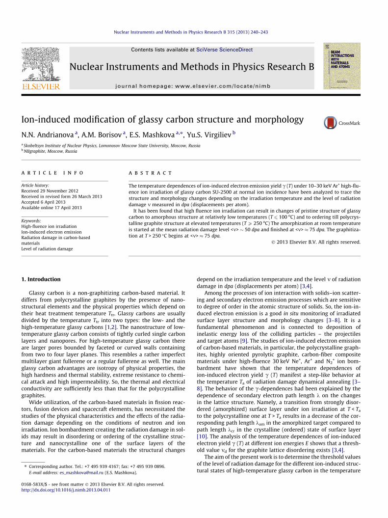
E , keVFig. 1. The energy dependence of the mean radiation damage level <m>. Thecalculations (squares) are taken from [4].
2.0
2.5
3.0
3.5
4.0RT MT HT
25 keV
SU-2500
15 keV
20 keV
30 keV
γ, el./ion
2. Experimental
The ion-induced modification was performed using themass-monochromator of the Skobeltsyn Institute of Nuclear Phys-ics, Lomonosov Moscow State University [11]. The 5–35 keV ionbeam was produced in an arc source with a longitudinal magneticfield. The ions are separated and the beam is focused by a Siegban-type magnetic sector field. The experimental procedure has beendescribed elsewhere [4,5]. The target holder allowed variation ofion incidence angle, and also to change target’s temperature from(–180o) up to 1000oC. The samples of high-temperature glassycarbon SU-2500 (NIIgraphite production, Moscow, Russia,Ttr = 2500 oC) were irradiated at normal ion incidence by 10–30 keV Ar+ ion beam and target temperature variation was fromroom temperature (RT) to 400 �C. The total ion fluencies ut were1018 – 1019 ion/cm2, where u is the ion beam flux and t is the bom-bardment time. To trace the structure and morphology changes thetemperature dependences of ion-induced electron emission yield c(T) were measured. The yield c was determined as the ratio of theelectron current to the primary ion current with the instrument er-ror � 2.5%.
The crystalline structure of the surface layers was analyzed bythe method of reflection high energy electron diffraction (RHEED).The RHEED was performed in EMR-102 (Russian model) operatedat 50 kV and electron beam current 50 lA. Before and after ionirradiation the samples were analyzed by scanning electronmicroscopy (SEM) using LYRA3 TESCAN.
The level m of radiation damage measured in dpa has beendetermined as m = utrdam, where rdam is the radiation damagecross section [12] taking into account a surface boundary move-ment due to sputtering [4]. At the steady-state conditions a sta-tionary profile m(x) is achieved at ut > Rdn0/Y [3], where n0 istarget atomic concentration, Y – sputtering yield, Rd – the depthof defect production
mðxÞ ¼ n0
Y
Z Rd
xrdam x0ð Þdx0: ð1Þ
In studied argon ion energy range the energy dependence ofmean depth stationary level <m> of primary radiation damage iswell-approximated by the linear dependence <m> = 25.6 + 2.45E[keV], see Fig. 1.
0 50 100 150 200 250 300 350 4001.0
1.510 keV
temperature T, oC
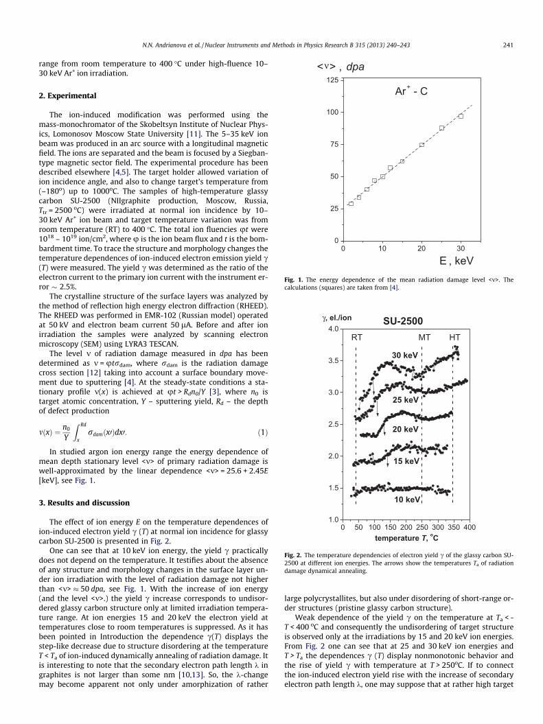
Fig. 2. The temperature dependencies of electron yield c of the glassy carbon SU-2500 at different ion energies. The arrows show the temperatures Ta of radiationdamage dynamical annealing.
3. Results and discussion
The effect of ion energy E on the temperature dependences ofion-induced electron yield c (T) at normal ion incidence for glassycarbon SU-2500 is presented in Fig. 2.
One can see that at 10 keV ion energy, the yield c practicallydoes not depend on the temperature. It testifies about the absenceof any structure and morphology changes in the surface layer un-der ion irradiation with the level of radiation damage not higherthan <m> � 50 dpa, see Fig. 1. With the increase of ion energy(and the level <m>.) the yield c increase corresponds to undisor-dered glassy carbon structure only at limited irradiation tempera-ture range. At ion energies 15 and 20 keV the electron yield attemperatures close to room temperatures is suppressed. As it hasbeen pointed in Introduction the dependence c(T) displays thestep-like decrease due to structure disordering at the temperatureT < Ta of ion-induced dynamically annealing of radiation damage. Itis interesting to note that the secondary electron path length k ingraphites is not larger than some nm [10,13]. So, the k-changemay become apparent not only under amorphization of rather
large polycrystallites, but also under disordering of short-range or-der structures (pristine glassy carbon structure).
Weak dependence of the yield c on the temperature at Ta < -T < 400 oC and consequently the undisordering of target structureis observed only at the irradiations by 15 and 20 keV ion energies.From Fig. 2 one can see that at 25 and 30 keV ion energies andT > Ta the dependences c (T) display nonmonotonic behavior andthe rise of yield c with temperature at T > 250oC. If to connectthe ion-induced electron yield rise with the increase of secondaryelectron path length k, one may suppose that at rather high target

a
b
c
242 N.N. Andrianova et al. / Nuclear Instruments and Methods in Physics Research B 315 (2013) 240–243
temperatures, ion energies and accordingly radiation damage levelit takes place the ordering of the glassy carbon structure to moreordered graphite structure. In other words, there are ion irradiationconditions for the ion-induced graphitization of the glassy carbon.The described regularities and the assumption about the glassycarbon SU-2500 graphitization are confirmed by the SEM andRHEED data.
The comparison of the SEM patterns made for surfaces irradi-ated by 30 keV Ar+ ion at different temperatures shows the threetypes of ion-induced morphology, see Fig. 3. After irradiation atRT the SEM micrographs show the etch pits with pentagon andhexagon forms (Fig. 3a), which is similar to that shown earlierfor disordered HOPG [14]. At the temperatures T = 140 and250 �C the qualitative difference between developed morphologyis absent, see Fig. 3b. The sputtering results in the shallow-cellularpattern are reflecting the globular-ribbon structure of glassycarbon, cf. [10,15]. At higher temperatures SU-2500 ion-inducedgraphitization leads to the morphology similar to irradiated poly-crystalline graphite [16].
There are also three types of the observed RHEED patterns forsurfaces irradiated by 30 keV Ar+ ion at different temperatures,see Fig. 4. Before irradiation and after irradiation at T = 250 oC theRHEED patterns of SU-2500 samples demonstrate the heavilysmeared rings. Probably, it reflects a pristine weakly ordered glassy
| |500 nm
| |500 nm
| |500 nm
a
b
c
——
——
——
Fig. 3. SEM micrographs (tilt 30�) of the glassy carbon SU-2500 surface after 30 keVAr+ ion irradiation (normal incidence) at RT (a), 250 (b) and 400 �C (c). ut = 1018 ion/cm2.
d
Fig. 4. RHEED patterns before (a) and after high fluence 30 keV Ar+ ion irradiation atnormal incidence of high-temperature glassy carbon SU-2500: (b) – RT; (c) –T = 250 oC and (d) T = 400 oC. ut = 1018 ion/cm2.
carbon structure. Ion irradiation at room temperatures results in adiffused halo typical for disordered surface layers, see Fig. 4b andcf. Fig. 4b in [15]. The diffraction patterns after ion irradiation attemperatures T > 250 oC are different both from the RHEEDpatterns before irradiation and from the ones taken when ion irra-diation was made at T < Ta. Ion irradiation results in appearanceslightly smeared three polycrystalline diffraction rings, seeFig. 4d. The diffraction pattern close to one for polycrystallinegraphite was observed earlier (Fig. 4c in [15]) at 30 keV N2
+ ionirradiation of high-temperature glassy carbon SU-2000 at elevatedtemperatures.
So, one can conclude that at sufficient radiation damage levelthe ion irradiation can result in the changes of pristine structureof glassy carbons to amorphous structure at relatively lowtemperatures (T < Ta) and to ordering till polycrystalline graphitestructure at elevated temperatures. The effect of ion energy E on
5 10 15 20 25 300.8
0.9
1.0
1.1HT / MT
RT/ MT
E, keV
RT,
HT/ M
T
40 50 60 70 80 90 100< >, dpa
γγ
γ γ
γ γ
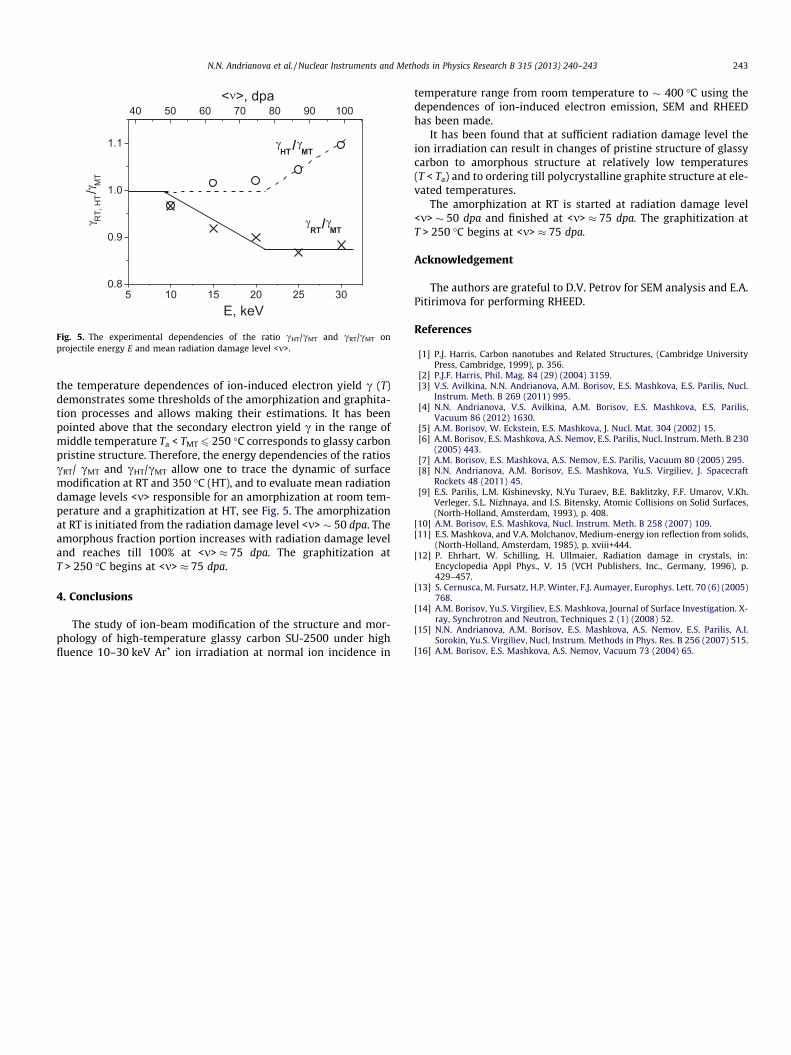
Fig. 5. The experimental dependencies of the ratio cHT/cMT and cRT/cMT onprojectile energy E and mean radiation damage level <m>.
N.N. Andrianova et al. / Nuclear Instruments and Methods in Physics Research B 315 (2013) 240–243 243
the temperature dependences of ion-induced electron yield c (T)demonstrates some thresholds of the amorphization and graphita-tion processes and allows making their estimations. It has beenpointed above that the secondary electron yield c in the range ofmiddle temperature Ta < TMT 6 250 �C corresponds to glassy carbonpristine structure. Therefore, the energy dependencies of the ratioscRT/ cMT and cHT/cMT allow one to trace the dynamic of surfacemodification at RT and 350 �C (HT), and to evaluate mean radiationdamage levels <m> responsible for an amorphization at room tem-perature and a graphitization at HT, see Fig. 5. The amorphizationat RT is initiated from the radiation damage level <m> � 50 dpa. Theamorphous fraction portion increases with radiation damage leveland reaches till 100% at <m> � 75 dpa. The graphitization atT > 250 �C begins at <m> � 75 dpa.
4. Conclusions
The study of ion-beam modification of the structure and mor-phology of high-temperature glassy carbon SU-2500 under highfluence 10–30 keV Ar+ ion irradiation at normal ion incidence in
temperature range from room temperature to � 400 �C using thedependences of ion-induced electron emission, SEM and RHEEDhas been made.
It has been found that at sufficient radiation damage level theion irradiation can result in changes of pristine structure of glassycarbon to amorphous structure at relatively low temperatures(T < Ta) and to ordering till polycrystalline graphite structure at ele-vated temperatures.
The amorphization at RT is started at radiation damage level<m> � 50 dpa and finished at <m> � 75 dpa. The graphitization atT > 250 �C begins at <m> � 75 dpa.
Acknowledgement
The authors are grateful to D.V. Petrov for SEM analysis and E.A.Pitirimova for performing RHEED.
References
[1] P.J. Harris, Carbon nanotubes and Related Structures, (Cambridge UniversityPress, Cambridge, 1999), p. 356.
[2] P.J.F. Harris, Phil. Mag. 84 (29) (2004) 3159.[3] V.S. Avilkina, N.N. Andrianova, A.M. Borisov, E.S. Mashkova, E.S. Parilis, Nucl.
Instrum. Meth. B 269 (2011) 995.[4] N.N. Andrianova, V.S. Avilkina, A.M. Borisov, E.S. Mashkova, E.S. Parilis,
Vacuum 86 (2012) 1630.[5] A.M. Borisov, W. Eckstein, E.S. Mashkova, J. Nucl. Mat. 304 (2002) 15.[6] A.M. Borisov, E.S. Mashkova, A.S. Nemov, E.S. Parilis, Nucl. Instrum. Meth. B 230
(2005) 443.[7] A.M. Borisov, E.S. Mashkova, A.S. Nemov, E.S. Parilis, Vacuum 80 (2005) 295.[8] N.N. Andrianova, A.M. Borisov, E.S. Mashkova, Yu.S. Virgiliev, J. Spacecraft
Rockets 48 (2011) 45.[9] E.S. Parilis, L.M. Kishinevsky, N.Yu Turaev, B.E. Baklitzky, F.F. Umarov, V.Kh.
Verleger, S.L. Nizhnaya, and I.S. Bitensky, Atomic Collisions on Solid Surfaces,(North-Holland, Amsterdam, 1993), p. 408.
[10] A.M. Borisov, E.S. Mashkova, Nucl. Instrum. Meth. B 258 (2007) 109.[11] E.S. Mashkova, and V.A. Molchanov, Medium-energy ion reflection from solids,
(North-Holland, Amsterdam, 1985), p. xviii+444.[12] P. Ehrhart, W. Schilling, H. Ullmaier, Radiation damage in crystals, in:
Encyclopedia Appl Phys., V. 15 (VCH Publishers, Inc., Germany, 1996), p.429–457.
[13] S. Cernusca, M. Fursatz, H.P. Winter, F.J. Aumayer, Europhys. Lett. 70 (6) (2005)768.
[14] A.M. Borisov, Yu.S. Virgiliev, E.S. Mashkova, Journal of Surface Investigation. X-ray, Synchrotron and Neutron, Techniques 2 (1) (2008) 52.
[15] N.N. Andrianova, A.M. Borisov, E.S. Mashkova, A.S. Nemov, E.S. Parilis, A.I.Sorokin, Yu.S. Virgiliev, Nucl, Instrum. Methods in Phys. Res. B 256 (2007) 515.
[16] A.M. Borisov, E.S. Mashkova, A.S. Nemov, Vacuum 73 (2004) 65.