
ioLogik E1200 Series User's Manual - MOXA€¦ · ioLogik E1200 Series User’s Manual . ... EDS...
115
ioLogik E1200 Series User’s Manual Edition 12.0, October 2016 www.moxa.com/product © 2016 Moxa Inc. All rights reserved.
Transcript of ioLogik E1200 Series User's Manual - MOXA€¦ · ioLogik E1200 Series User’s Manual . ... EDS...

ioLogik E1200 Series User’s Manual
Edition 12.0, October 2016
www.moxa.com/product
© 2016 Moxa Inc. All rights reserved.

ioLogik E1200 Series User’s Manual
The software described in this manual is furnished under a license agreement and may be used only in accordance with the terms of that agreement.
Copyright Notice
© 2016 Moxa Inc. All rights reserved.
Trademarks
The MOXA logo is a registered trademark of Moxa Inc. All other trademarks or registered marks in this manual belong to their respective manufacturers.
Disclaimer
Information in this document is subject to change without notice and does not represent a commitment on the part of Moxa.
Moxa provides this document as is, without warranty of any kind, either expressed or implied, including, but not limited to, its particular purpose. Moxa reserves the right to make improvements and/or changes to this manual, or to the products and/or the programs described in this manual, at any time.
Information provided in this manual is intended to be accurate and reliable. However, Moxa assumes no responsibility for its use, or for any infringements on the rights of third parties that may result from its use.
This product might include unintentional technical or typographical errors. Changes are periodically made to the information herein to correct such errors, and these changes are incorporated into new editions of the publication.
Technical Support Contact Information
www.moxa.com/support
Moxa Americas Toll-free: 1-888-669-2872 Tel: +1-714-528-6777 Fax: +1-714-528-6778
Moxa China (Shanghai office) Toll-free: 800-820-5036 Tel: +86-21-5258-9955 Fax: +86-21-5258-5505
Moxa Europe Tel: +49-89-3 70 03 99-0 Fax: +49-89-3 70 03 99-99
Moxa Asia-Pacific Tel: +886-2-8919-1230 Fax: +886-2-8919-1231
Moxa India Tel: +91-80-4172-9088 Fax: +91-80-4132-1045
Table of Contents
1. Introduction ...................................................................................................................................... 1-1 Product Features ................................................................................................................................ 1-2 Inside the Box .................................................................................................................................... 1-2 Product Model Information ................................................................................................................... 1-2 Product Specifications ......................................................................................................................... 1-3
Common Specifications ................................................................................................................ 1-3 ioLogik E1210 ............................................................................................................................. 1-4 ioLogik E1211 ............................................................................................................................. 1-4 ioLogik E1212 ............................................................................................................................. 1-5 ioLogik E1213 ............................................................................................................................. 1-6 ioLogik E1214 ............................................................................................................................. 1-7 ioLogik E1240 ............................................................................................................................. 1-8 ioLogik E1241 ............................................................................................................................. 1-8 ioLogik E1242 ............................................................................................................................. 1-9 ioLogik E1260 ........................................................................................................................... 1-10 ioLogik E1262 ........................................................................................................................... 1-11
Physical Dimensions .......................................................................................................................... 1-12 Hardware Reference .......................................................................................................................... 1-13
Panel Guide .............................................................................................................................. 1-13 Ethernet Port ............................................................................................................................ 1-13 LED Indicators .......................................................................................................................... 1-13
I/O Circuit Diagram ........................................................................................................................... 1-14 DI Circuit ................................................................................................................................. 1-14 Sinking DO Circuit ..................................................................................................................... 1-14 Sourcing DO Circuit ................................................................................................................... 1-15 DIO Circuit ............................................................................................................................... 1-16 Relay Circuit ............................................................................................................................. 1-17 AI Circuit .................................................................................................................................. 1-17 RTD Circuit ............................................................................................................................... 1-17 TC Circuit ................................................................................................................................. 1-18
2. Initial Setup ...................................................................................................................................... 2-1 Hardware Installation .......................................................................................................................... 2-2
Connecting the Power .................................................................................................................. 2-2 Grounding the ioLogik E1200 ........................................................................................................ 2-2 DIN Rail, Wall Mounting ............................................................................................................... 2-2 Connecting to the Network ........................................................................................................... 2-3 Jumper Settings (DIO and AI) ....................................................................................................... 2-3 I/O Wiring Diagrams .................................................................................................................... 2-5
ioSearch™ Installation ......................................................................................................................... 2-7 Load Factory Default Settings ............................................................................................................... 2-7
3. Using the Web Console ...................................................................................................................... 3-1 Introduction to the Web Console ........................................................................................................... 3-2 Overview ........................................................................................................................................... 3-3 Network Settings for the Web Console ................................................................................................... 3-4
General Settings ......................................................................................................................... 3-4 Ethernet Configuration ................................................................................................................. 3-4
User-Defined Modbus Addressing .......................................................................................................... 3-5 Default Modbus Address ............................................................................................................... 3-5
AOPC Server Settings .......................................................................................................................... 3-6 Tag Generation ........................................................................................................................... 3-6
I/O Settings ....................................................................................................................................... 3-8 DI Channels ................................................................................................................................ 3-8 DO Channels ............................................................................................................................. 3-10 AI Channels .............................................................................................................................. 3-11 AI Input Range ......................................................................................................................... 3-12 AO Channels ............................................................................................................................. 3-14 RTD Channels ........................................................................................................................... 3-15 TC Channels ............................................................................................................................. 3-17
Peer-to-Peer Networking ................................................................................................................... 3-18 Peer-to-Peer Settings (1-50) ...................................................................................................... 3-18 Sample Peer-to-Peer Configuration .............................................................................................. 3-19 DO Safe Mode Settings .............................................................................................................. 3-20 AO Safe Mode Settings ............................................................................................................... 3-20
SNMP .............................................................................................................................................. 3-20 SNMP Trap ............................................................................................................................... 3-20 Using SNMP .............................................................................................................................. 3-21 Accessibility IP List .................................................................................................................... 3-25
RESTful API Setting .......................................................................................................................... 3-26 EtherNet/IP Setting ........................................................................................................................... 3-26 System Management ......................................................................................................................... 3-27
Network Connection .................................................................................................................. 3-27 Firmware Update ....................................................................................................................... 3-27 Import System Configuration Settings ......................................................................................... 3-27 Export System Settings .............................................................................................................. 3-28
Change Password ............................................................................................................................. 3-28 Load Factory Defaults ........................................................................................................................ 3-28 Save/Restart .................................................................................................................................... 3-29
4. Using ioSearch™ ................................................................................................................................ 4-1 Introduction to ioSearch™ ................................................................................................................... 4-2 ioSearch™ Main Screen ....................................................................................................................... 4-2
Main Screen Overview.................................................................................................................. 4-2 ioSearch™ Setup ................................................................................................................................ 4-3
System ...................................................................................................................................... 4-3 Sort ........................................................................................................................................... 4-4 Quick Links ................................................................................................................................. 4-4
Main Function ..................................................................................................................................... 4-4 Locate ....................................................................................................................................... 4-5 Firmware Upgrade ....................................................................................................................... 4-5 Unlock ....................................................................................................................................... 4-5 Import ....................................................................................................................................... 4-6 Export ....................................................................................................................................... 4-6 Change IP Address ...................................................................................................................... 4-7 Batch TCP/IP Configuration on Multiple Devices ............................................................................... 4-7 Change Server Name ................................................................................................................... 4-8 Activate EtherNet/IP .................................................................................................................... 4-8 Restart System ........................................................................................................................... 4-9 Reset to Default ........................................................................................................................ 4-10 Mass Deployment (Import) ......................................................................................................... 4-10 Mass Deployment (Export) ......................................................................................................... 4-10
5. Activation Process for the EtherNet/IP Function .............................................................................. 5-1 6. How to Connect the ioLogik E1200 to an Allen-Bradley PLC .............................................................. 6-1
EDS Installation of the ioLogik E1200 Series in Rockwell Software RSLogix 5000 ........................................ 6-2 Establishing communication between the ioLogik E1200 device and the Allen-Bradley PLC ........................... 6-6
A. Modbus/TCP Default Address Mappings ............................................................................................ A-1 ioLogik E1210 Modbus Address and Register Map ................................................................................... A-2 ioLogik E1211 Modbus Address and Register Map ................................................................................... A-3 ioLogik E1212 Modbus Address and Register Map ................................................................................... A-5 ioLogik E1213 Modbus Address and Register Map ................................................................................... A-7 ioLogik E1214 Modbus Address and Register Map ................................................................................... A-9 ioLogik E1240 Modbus Address and Register Map ................................................................................. A-11 ioLogik E1241 Modbus Address and Register Map ................................................................................. A-12 ioLogik E1242 Modbus Address and Register Map ................................................................................. A-14 ioLogik E1260 Modbus Address and Register Map ................................................................................. A-16 ioLogik E1262 Modbus Address and Register Map ................................................................................. A-18
B. EtherNet/IP Default Address Mappings ............................................................................................ B-1 ioLogik E1200 EtherNet/IP Map ............................................................................................................ B-1
C. RESTful API Default Address Mappings ............................................................................................. C-1 ioLogik E1200 RESTful API Map ............................................................................................................ C-1
D. Network Port Numbers ...................................................................................................................... D-1 E. Factory Default Settings .................................................................................................................... E-1 F. Pinouts .............................................................................................................................................. F-1 G. FCC Interference Statement .............................................................................................................. G-1 H. European Community (CE) ................................................................................................................ H-1
1 1. Introduction
The ioLogik E1200 industrial Ethernet remote I/O has two embedded Ethernet switch ports that allow information to flow to another local Ethernet device or connect to the next ioLogik in a daisy-chain. Applications such as factory automation, security and surveillance systems, and tunnel monitoring, can make use of daisy-chained Ethernet for building multidrop I/O networks over standard Ethernet cables and familiar fieldbus protocols. The daisy-chain function on the ioLogik E1200 Ethernet remote I/O not only increases the connections between machines and panels, but it also lowers the cost of buying separate Ethernet switches, and at the same time reduces labor fees and cabling by a large percentage. For example, if a production facility contains 700 stations (20 points per station), the wiring cost reduction can reach 15% of the total implementation cost.
The following topics are covered in this chapter:
Product Features
Inside the Box
Product Model Information
Product Specifications
Common Specifications
ioLogik E1210
ioLogik E1211
ioLogik E1212
ioLogik E1213
ioLogik E1214
ioLogik E1240
ioLogik E1241
ioLogik E1242
ioLogik E1260
ioLogik E1262
Physical Dimensions
Hardware Reference
Panel Guide
Ethernet Port
LED Indicators
I/O Circuit Diagram
DI Circuit
Sinking DO Circuit
Sourcing DO Circuit
DIO Circuit
Relay Circuit
AI Circuit
RTD Circuit
TC Circuit
ioLogik E1200 Series Introduction
1-2
Product Features • Active communication with patented MX-AOPC UA Server • 2-port Ethernet switch for daisy-chain topologies • Easy mass deployment and configuration with ioSearch™utility • User-friendly configuration via web browser • Save time and wiring costs with peer-to-peer communication • User-defined Modbus/TCP addressing • Simplify I/O management with MXIO library on either Windows or Linux platform • Wide operating temperature: -40 to 75°C (-40 to 167°F) • Supports SNMPv1/v2c • UL/cUL Class I Division 2, ATEX Zone 2 certification
Inside the Box The ioLogik E1200 is shipped with the following items:
• ioLogik E1200 remote Ethernet I/O server • Quick installation guide (printed)
NOTE Notify your sales representative if any of the above items are missing or damaged.
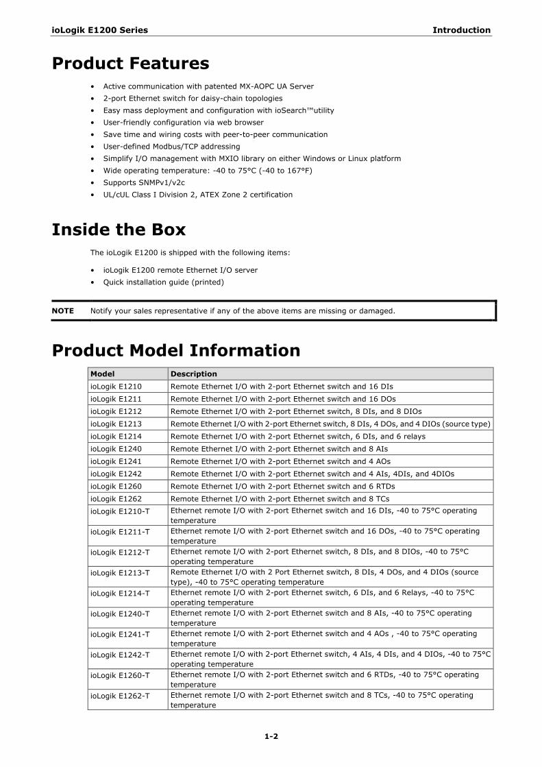
Product Model Information Model Description
ioLogik E1210 Remote Ethernet I/O with 2-port Ethernet switch and 16 DIs
ioLogik E1211 Remote Ethernet I/O with 2-port Ethernet switch and 16 DOs
ioLogik E1212 Remote Ethernet I/O with 2-port Ethernet switch, 8 DIs, and 8 DIOs
ioLogik E1213 Remote Ethernet I/O with 2-port Ethernet switch, 8 DIs, 4 DOs, and 4 DIOs (source type)
ioLogik E1214 Remote Ethernet I/O with 2-port Ethernet switch, 6 DIs, and 6 relays
ioLogik E1240 Remote Ethernet I/O with 2-port Ethernet switch and 8 AIs
ioLogik E1241 Remote Ethernet I/O with 2-port Ethernet switch and 4 AOs
ioLogik E1242 Remote Ethernet I/O with 2-port Ethernet switch and 4 AIs, 4DIs, and 4DIOs
ioLogik E1260 Remote Ethernet I/O with 2-port Ethernet switch and 6 RTDs
ioLogik E1262 Remote Ethernet I/O with 2-port Ethernet switch and 8 TCs
ioLogik E1210-T Ethernet remote I/O with 2-port Ethernet switch and 16 DIs, -40 to 75°C operating temperature
ioLogik E1211-T Ethernet remote I/O with 2-port Ethernet switch and 16 DOs, -40 to 75°C operating temperature
ioLogik E1212-T Ethernet remote I/O with 2-port Ethernet switch, 8 DIs, and 8 DIOs, -40 to 75°C operating temperature
ioLogik E1213-T Remote Ethernet I/O with 2 Port Ethernet switch, 8 DIs, 4 DOs, and 4 DIOs (source type), -40 to 75°C operating temperature
ioLogik E1214-T Ethernet remote I/O with 2-port Ethernet switch, 6 DIs, and 6 Relays, -40 to 75°C operating temperature
ioLogik E1240-T Ethernet remote I/O with 2-port Ethernet switch and 8 AIs, -40 to 75°C operating temperature
ioLogik E1241-T Ethernet remote I/O with 2-port Ethernet switch and 4 AOs , -40 to 75°C operating temperature
ioLogik E1242-T Ethernet remote I/O with 2-port Ethernet switch, 4 AIs, 4 DIs, and 4 DIOs, -40 to 75°C operating temperature
ioLogik E1260-T Ethernet remote I/O with 2-port Ethernet switch and 6 RTDs, -40 to 75°C operating temperature
ioLogik E1262-T Ethernet remote I/O with 2-port Ethernet switch and 8 TCs, -40 to 75°C operating temperature
ioLogik E1200 Series Introduction
1-3
Product Specifications
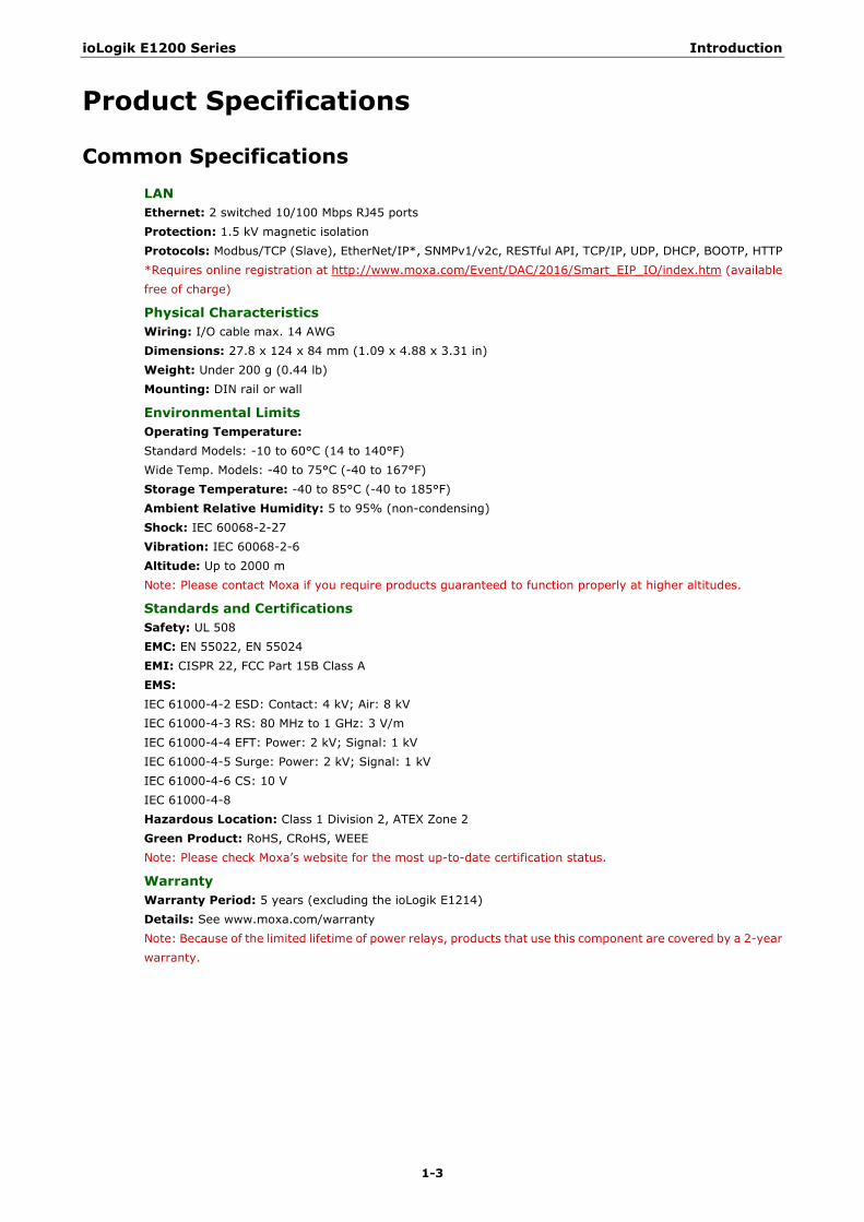
Common Specifications LAN Ethernet: 2 switched 10/100 Mbps RJ45 ports Protection: 1.5 kV magnetic isolation Protocols: Modbus/TCP (Slave), EtherNet/IP*, SNMPv1/v2c, RESTful API, TCP/IP, UDP, DHCP, BOOTP, HTTP *Requires online registration at http://www.moxa.com/Event/DAC/2016/Smart_EIP_IO/index.htm (available free of charge)
Physical Characteristics Wiring: I/O cable max. 14 AWG Dimensions: 27.8 x 124 x 84 mm (1.09 x 4.88 x 3.31 in) Weight: Under 200 g (0.44 lb) Mounting: DIN rail or wall
Environmental Limits Operating Temperature: Standard Models: -10 to 60°C (14 to 140°F) Wide Temp. Models: -40 to 75°C (-40 to 167°F) Storage Temperature: -40 to 85°C (-40 to 185°F) Ambient Relative Humidity: 5 to 95% (non-condensing) Shock: IEC 60068-2-27 Vibration: IEC 60068-2-6 Altitude: Up to 2000 m Note: Please contact Moxa if you require products guaranteed to function properly at higher altitudes.
Standards and Certifications Safety: UL 508 EMC: EN 55022, EN 55024 EMI: CISPR 22, FCC Part 15B Class A EMS: IEC 61000-4-2 ESD: Contact: 4 kV; Air: 8 kV IEC 61000-4-3 RS: 80 MHz to 1 GHz: 3 V/m IEC 61000-4-4 EFT: Power: 2 kV; Signal: 1 kV IEC 61000-4-5 Surge: Power: 2 kV; Signal: 1 kV IEC 61000-4-6 CS: 10 V IEC 61000-4-8 Hazardous Location: Class 1 Division 2, ATEX Zone 2 Green Product: RoHS, CRoHS, WEEE Note: Please check Moxa’s website for the most up-to-date certification status.
Warranty Warranty Period: 5 years (excluding the ioLogik E1214) Details: See www.moxa.com/warranty Note: Because of the limited lifetime of power relays, products that use this component are covered by a 2-year warranty.
ioLogik E1200 Series Introduction
1-4
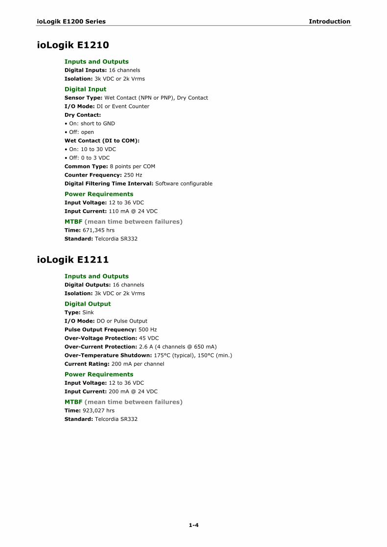
ioLogik E1210 Inputs and Outputs Digital Inputs: 16 channels Isolation: 3k VDC or 2k Vrms
Digital Input Sensor Type: Wet Contact (NPN or PNP), Dry Contact I/O Mode: DI or Event Counter Dry Contact: • On: short to GND • Off: open Wet Contact (DI to COM): • On: 10 to 30 VDC • Off: 0 to 3 VDC Common Type: 8 points per COM Counter Frequency: 250 Hz Digital Filtering Time Interval: Software configurable
Power Requirements Input Voltage: 12 to 36 VDC Input Current: 110 mA @ 24 VDC
MTBF (mean time between failures) Time: 671,345 hrs Standard: Telcordia SR332
ioLogik E1211 Inputs and Outputs Digital Outputs: 16 channels Isolation: 3k VDC or 2k Vrms
Digital Output Type: Sink I/O Mode: DO or Pulse Output Pulse Output Frequency: 500 Hz Over-Voltage Protection: 45 VDC Over-Current Protection: 2.6 A (4 channels @ 650 mA) Over-Temperature Shutdown: 175°C (typical), 150°C (min.) Current Rating: 200 mA per channel
Power Requirements Input Voltage: 12 to 36 VDC Input Current: 200 mA @ 24 VDC
MTBF (mean time between failures) Time: 923,027 hrs Standard: Telcordia SR332
ioLogik E1200 Series Introduction
1-5
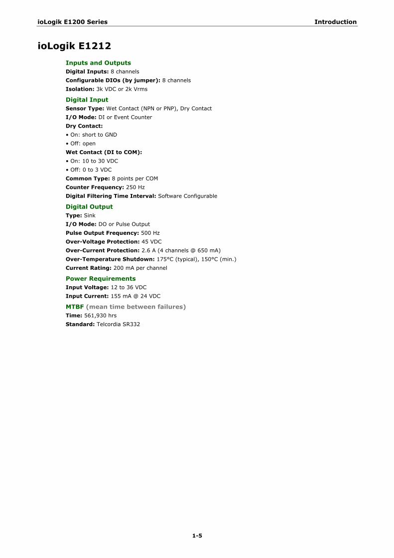
ioLogik E1212 Inputs and Outputs Digital Inputs: 8 channels Configurable DIOs (by jumper): 8 channels Isolation: 3k VDC or 2k Vrms
Digital Input Sensor Type: Wet Contact (NPN or PNP), Dry Contact I/O Mode: DI or Event Counter Dry Contact: • On: short to GND • Off: open Wet Contact (DI to COM): • On: 10 to 30 VDC • Off: 0 to 3 VDC Common Type: 8 points per COM Counter Frequency: 250 Hz Digital Filtering Time Interval: Software Configurable
Digital Output Type: Sink I/O Mode: DO or Pulse Output Pulse Output Frequency: 500 Hz Over-Voltage Protection: 45 VDC Over-Current Protection: 2.6 A (4 channels @ 650 mA) Over-Temperature Shutdown: 175°C (typical), 150°C (min.) Current Rating: 200 mA per channel
Power Requirements Input Voltage: 12 to 36 VDC Input Current: 155 mA @ 24 VDC
MTBF (mean time between failures) Time: 561,930 hrs Standard: Telcordia SR332
ioLogik E1200 Series Introduction
1-6
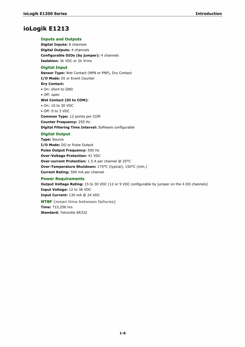
ioLogik E1213 Inputs and Outputs Digital Inputs: 8 channels Digital Outputs: 4 channels Configurable DIOs (by jumper): 4 channels Isolation: 3k VDC or 2k Vrms
Digital Input Sensor Type: Wet Contact (NPN or PNP), Dry Contact I/O Mode: DI or Event Counter Dry Contact: • On: short to GND • Off: open Wet Contact (DI to COM): • On: 10 to 30 VDC • Off: 0 to 3 VDC Common Type: 12 points per COM Counter Frequency: 250 Hz Digital Filtering Time Interval: Software configurable
Digital Output Type: Source I/O Mode: DO or Pulse Output Pulse Output Frequency: 500 Hz Over-Voltage Protection: 41 VDC Over-current Protection: 1.5 A per channel @ 25°C Over-Temperature Shutdown: 175°C (typical), 150°C (min.) Current Rating: 500 mA per channel
Power Requirements Output Voltage Rating: 15 to 30 VDC (12 or 9 VDC configurable by jumper on the 4 DO channels) Input Voltage: 12 to 36 VDC Input Current: 130 mA @ 24 VDC
MTBF (mean time between failures) Time: 715,256 hrs Standard: Telcordia SR332
ioLogik E1200 Series Introduction
1-7
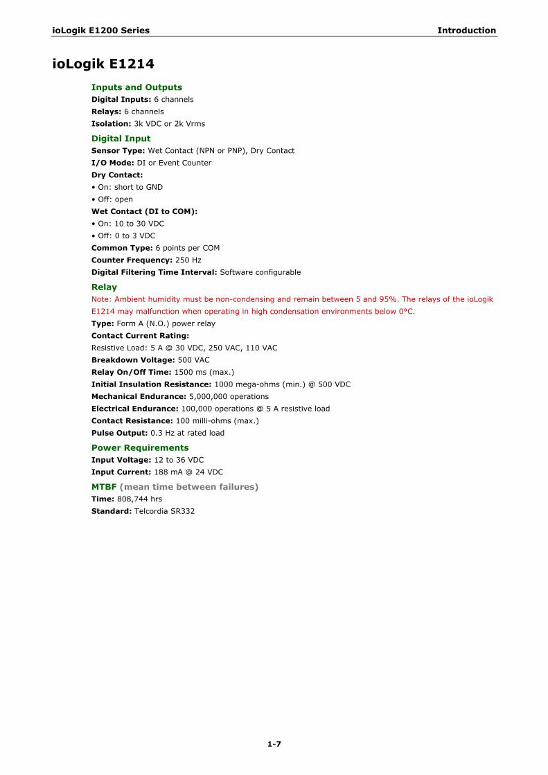
ioLogik E1214 Inputs and Outputs Digital Inputs: 6 channels Relays: 6 channels Isolation: 3k VDC or 2k Vrms
Digital Input Sensor Type: Wet Contact (NPN or PNP), Dry Contact I/O Mode: DI or Event Counter Dry Contact: • On: short to GND • Off: open Wet Contact (DI to COM): • On: 10 to 30 VDC • Off: 0 to 3 VDC Common Type: 6 points per COM Counter Frequency: 250 Hz Digital Filtering Time Interval: Software configurable
Relay Note: Ambient humidity must be non-condensing and remain between 5 and 95%. The relays of the ioLogik E1214 may malfunction when operating in high condensation environments below 0°C. Type: Form A (N.O.) power relay Contact Current Rating: Resistive Load: 5 A @ 30 VDC, 250 VAC, 110 VAC Breakdown Voltage: 500 VAC Relay On/Off Time: 1500 ms (max.) Initial Insulation Resistance: 1000 mega-ohms (min.) @ 500 VDC Mechanical Endurance: 5,000,000 operations Electrical Endurance: 100,000 operations @ 5 A resistive load Contact Resistance: 100 milli-ohms (max.) Pulse Output: 0.3 Hz at rated load
Power Requirements Input Voltage: 12 to 36 VDC Input Current: 188 mA @ 24 VDC
MTBF (mean time between failures) Time: 808,744 hrs Standard: Telcordia SR332
ioLogik E1200 Series Introduction
1-8
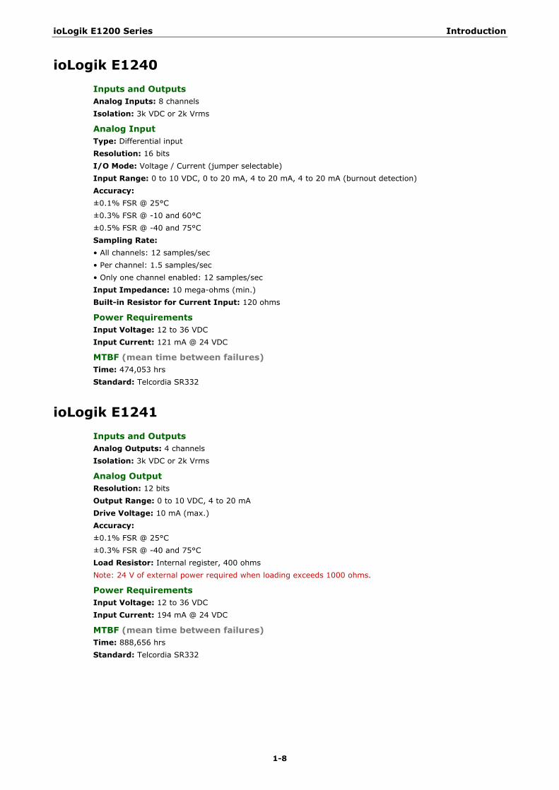
ioLogik E1240 Inputs and Outputs Analog Inputs: 8 channels Isolation: 3k VDC or 2k Vrms
Analog Input Type: Differential input Resolution: 16 bits I/O Mode: Voltage / Current (jumper selectable) Input Range: 0 to 10 VDC, 0 to 20 mA, 4 to 20 mA, 4 to 20 mA (burnout detection) Accuracy: ±0.1% FSR @ 25°C ±0.3% FSR @ -10 and 60°C ±0.5% FSR @ -40 and 75°C Sampling Rate: • All channels: 12 samples/sec • Per channel: 1.5 samples/sec • Only one channel enabled: 12 samples/sec Input Impedance: 10 mega-ohms (min.) Built-in Resistor for Current Input: 120 ohms
Power Requirements Input Voltage: 12 to 36 VDC Input Current: 121 mA @ 24 VDC
MTBF (mean time between failures) Time: 474,053 hrs Standard: Telcordia SR332
ioLogik E1241 Inputs and Outputs Analog Outputs: 4 channels Isolation: 3k VDC or 2k Vrms
Analog Output Resolution: 12 bits Output Range: 0 to 10 VDC, 4 to 20 mA Drive Voltage: 10 mA (max.) Accuracy: ±0.1% FSR @ 25°C ±0.3% FSR @ -40 and 75°C Load Resistor: Internal register, 400 ohms Note: 24 V of external power required when loading exceeds 1000 ohms.
Power Requirements Input Voltage: 12 to 36 VDC Input Current: 194 mA @ 24 VDC
MTBF (mean time between failures) Time: 888,656 hrs Standard: Telcordia SR332
ioLogik E1200 Series Introduction
1-9
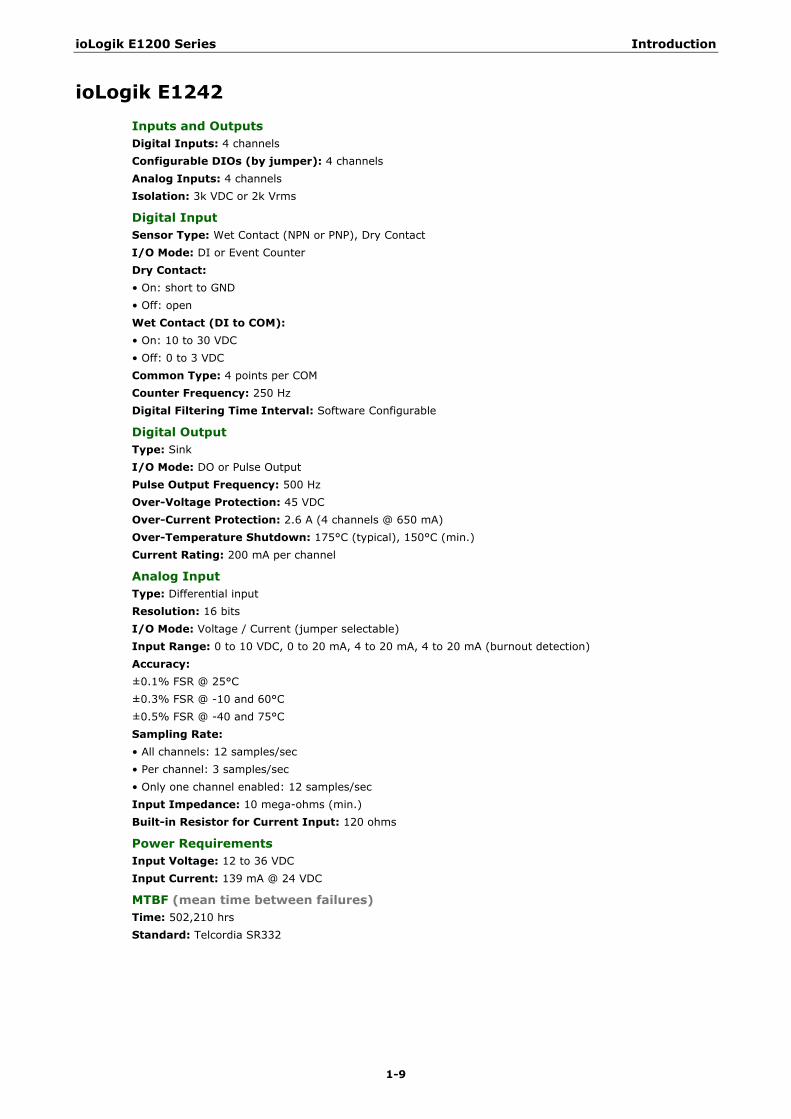
ioLogik E1242 Inputs and Outputs Digital Inputs: 4 channels Configurable DIOs (by jumper): 4 channels Analog Inputs: 4 channels Isolation: 3k VDC or 2k Vrms
Digital Input Sensor Type: Wet Contact (NPN or PNP), Dry Contact I/O Mode: DI or Event Counter Dry Contact: • On: short to GND • Off: open Wet Contact (DI to COM): • On: 10 to 30 VDC • Off: 0 to 3 VDC Common Type: 4 points per COM Counter Frequency: 250 Hz Digital Filtering Time Interval: Software Configurable
Digital Output Type: Sink I/O Mode: DO or Pulse Output Pulse Output Frequency: 500 Hz Over-Voltage Protection: 45 VDC Over-Current Protection: 2.6 A (4 channels @ 650 mA) Over-Temperature Shutdown: 175°C (typical), 150°C (min.) Current Rating: 200 mA per channel
Analog Input Type: Differential input Resolution: 16 bits I/O Mode: Voltage / Current (jumper selectable) Input Range: 0 to 10 VDC, 0 to 20 mA, 4 to 20 mA, 4 to 20 mA (burnout detection) Accuracy: ±0.1% FSR @ 25°C ±0.3% FSR @ -10 and 60°C ±0.5% FSR @ -40 and 75°C Sampling Rate: • All channels: 12 samples/sec • Per channel: 3 samples/sec • Only one channel enabled: 12 samples/sec Input Impedance: 10 mega-ohms (min.) Built-in Resistor for Current Input: 120 ohms
Power Requirements Input Voltage: 12 to 36 VDC Input Current: 139 mA @ 24 VDC
MTBF (mean time between failures) Time: 502,210 hrs Standard: Telcordia SR332
ioLogik E1200 Series Introduction
1-10
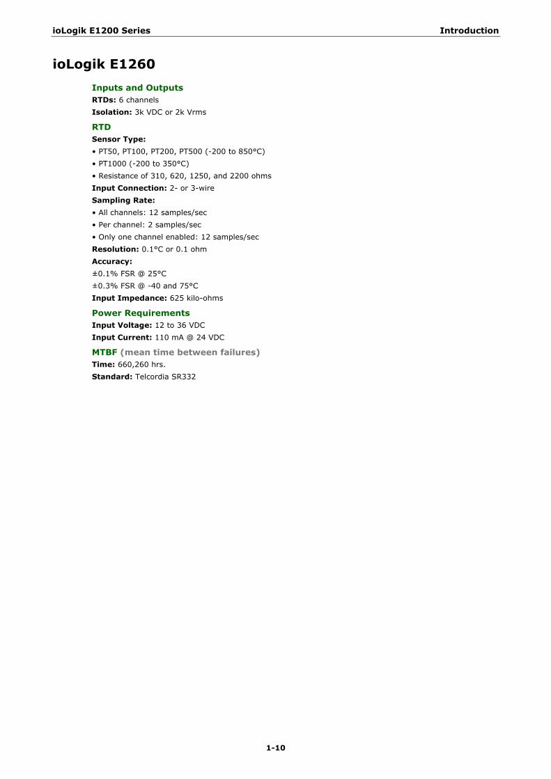
ioLogik E1260 Inputs and Outputs RTDs: 6 channels Isolation: 3k VDC or 2k Vrms
RTD Sensor Type: • PT50, PT100, PT200, PT500 (-200 to 850°C) • PT1000 (-200 to 350°C) • Resistance of 310, 620, 1250, and 2200 ohms Input Connection: 2- or 3-wire Sampling Rate: • All channels: 12 samples/sec • Per channel: 2 samples/sec • Only one channel enabled: 12 samples/sec Resolution: 0.1°C or 0.1 ohm Accuracy: ±0.1% FSR @ 25°C ±0.3% FSR @ -40 and 75°C Input Impedance: 625 kilo-ohms
Power Requirements Input Voltage: 12 to 36 VDC Input Current: 110 mA @ 24 VDC
MTBF (mean time between failures) Time: 660,260 hrs. Standard: Telcordia SR332
ioLogik E1200 Series Introduction
1-11
ioLogik E1262 Inputs and Outputs Thermocouples: 8 channels Isolation: 3k VDC or 2k Vrms
Thermocouple Sensor Type: J (0 to 750°C), K (-200 to 1250°C), T (-200 to 350°C), E (-200 to 900°C), R (-50 to 1600°C), S (-50 to 1760°C), B (600 to 1700°C), N (-200 to 1300°C) Millivolt Type: • Mode: ±78.126 mV, ±39.062 mV, ±19.532 mV • Fault and over-voltage protection: -35 to +35 VDC (power off) -25 to +30 VDC (power on) Sampling Rate: • All channels: 12 samples/sec • Per channel: 1.5 samples/sec • Only one channel enabled: 12 samples/sec Resolution: 16 bits Accuracy: ±0.1% FSR @ 25°C ±0.3% FSR @ -40 and 75°C Input Impedance: 10 mega-ohms
Power Requirements Input Voltage: 12 to 36 VDC Input Current: 118 mA @ 24 VDC
MTBF (mean time between failures) Time: 631,418 hrs. Standard: Telcordia SR332
ioLogik E1200 Series Introduction
1-12
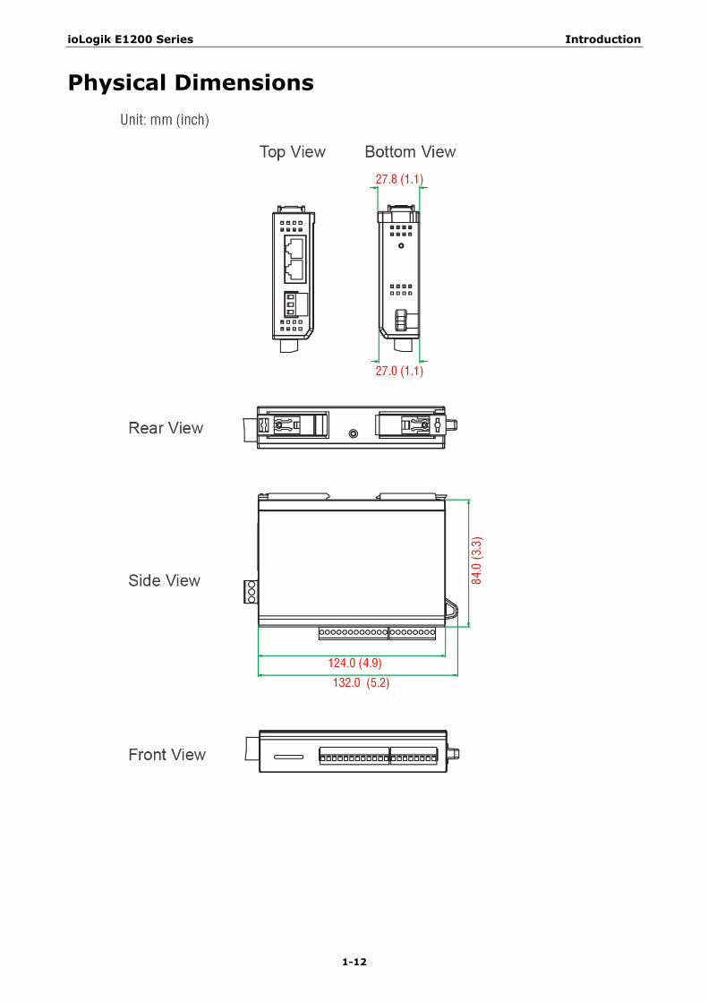
Physical Dimensions

ioLogik E1200 Series Introduction
1-13
Hardware Reference
Panel Guide
NOTE The RESET button restarts the server and resets all settings to factory defaults. Use a pointed object such as a straightened paper clip to hold down the RESET button for 5 seconds. The factory defaults will be loaded once the READY LED turns green again. You may then release the RESET button.
Ethernet Port
Pin 1 2 3 4
Signal TXD+ TXD- RXD+ ---
Pin 5 6 7 8
Signal --- RXD- --- ---
LED Indicators LED State Description
Power Amber System power is ON
OFF System power is OFF
Ready Green System is ready
Flashing Flashes every 1 second when the “Locate” function is triggered
Flashing Flashes every 0.5 second when the firmware is being upgraded
Flashing ON/OFF cycle period of 0.5 second represents “Safe Mode”
OFF System is not ready
Port 1 Green Ethernet connection enabled
Flashing Transmitting or receiving data
Port 2 Green Ethernet connection enabled
Flashing Transmitting or receiving data
EXT Green EXT field power input is connected
Off EXT field power input is disconnected
ioLogik E1200 Series Introduction
1-14
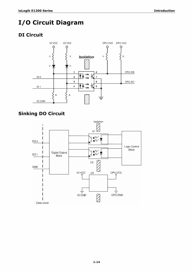
I/O Circuit Diagram
DI Circuit
Sinking DO Circuit
ioLogik E1200 Series Introduction
1-15
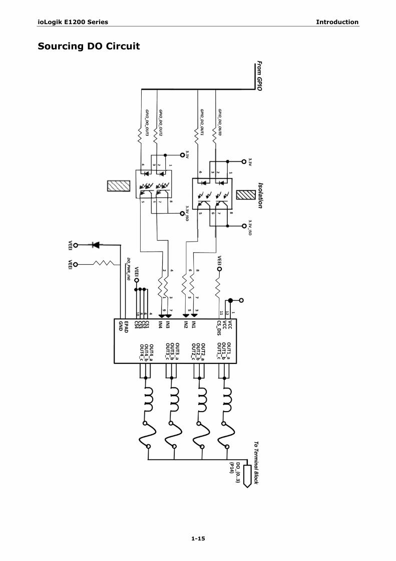
Sourcing DO Circuit
ioLogik E1200 Series Introduction
1-16
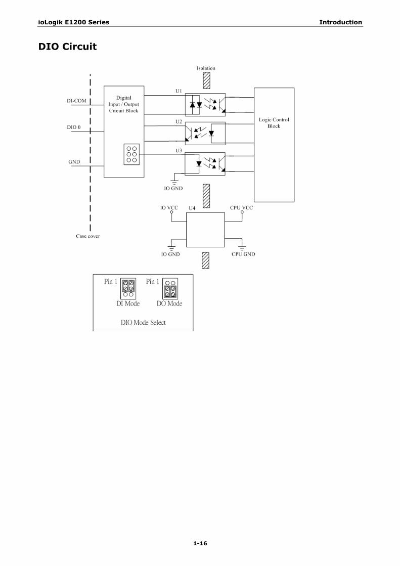
DIO Circuit
ioLogik E1200 Series Introduction
1-17
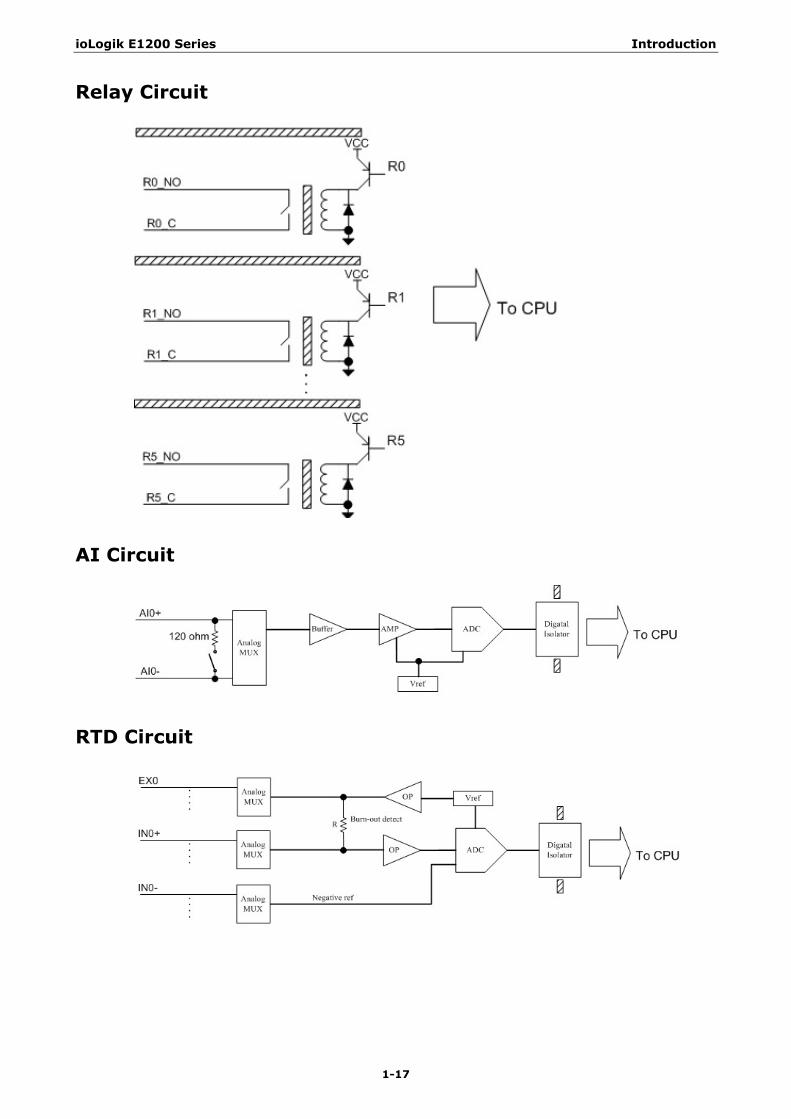
Relay Circuit
AI Circuit
RTD Circuit

ioLogik E1200 Series Introduction
1-18
TC Circuit
2 2. Initial Setup
This chapter describes how to install the ioLogik E1200.
The following topics are covered in this chapter:
Hardware Installation
Connecting the Power
Grounding the ioLogik E1200
DIN Rail, Wall Mounting
Connecting to the Network
Jumper Settings (DIO and AI)
I/O Wiring Diagrams
ioSearch™ Installation
Load Factory Default Settings

ioLogik E1200 Series Initial Setup
2-2
Hardware Installation
Connecting the Power Connect the 12 to 36 VDC power line to the ioLogik E1200’s terminal block on the top panel. If power is properly supplied, the Power LED will glow a solid amber color.
ATTENTION
Determine the maximum possible current for each power wire and common wire. Observe all electrical codes dictating the maximum current allowable for each wire size. If the current exceeds the maximum rating, the wiring may overheat, causing serious damage to your equipment. For safety reasons, we recommend an average cable size of 22 AWG. However, depending on the current load, you may want to adjust your cable size (the maximum wire size for power connectors is 2 mm).
Grounding the ioLogik E1200 The ioLogik E1200 is equipped with a grounding point on the terminal block located on the top panel.
Connect the ground pin ( ) if earth ground is available.
DIN Rail, Wall Mounting There are two sliders on the back of the unit for DIN rail and wall mounting.
Mounting on a DIN rail:
Pull out the bottom slider; latch the unit onto the DIN rail, and push the slider back in.
Mounting on the wall:
Pull out both the top and bottom sliders and align the screws accordingly.
ioLogik E1200 Series Initial Setup
2-3
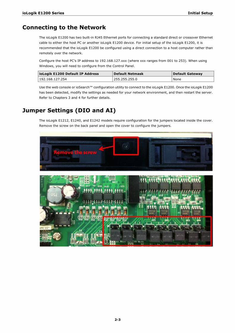
Connecting to the Network The ioLogik E1200 has two built-in RJ45 Ethernet ports for connecting a standard direct or crossover Ethernet cable to either the host PC or another ioLogik E1200 device. For initial setup of the ioLogik E1200, it is recommended that the ioLogik E1200 be configured using a direct connection to a host computer rather than remotely over the network.
Configure the host PC’s IP address to 192.168.127.xxx (where xxx ranges from 001 to 253). When using Windows, you will need to configure from the Control Panel.
ioLogik E1200 Default IP Address Default Netmask Default Gateway
192.168.127.254 255.255.255.0 None
Use the web console or ioSearch™ configuration utility to connect to the ioLogik E1200. Once the ioLogik E1200 has been detected, modify the settings as needed for your network environment, and then restart the server. Refer to Chapters 3 and 4 for further details.
Jumper Settings (DIO and AI) The ioLogik E1212, E1240, and E1242 models require configuration for the jumpers located inside the cover. Remove the screw on the back panel and open the cover to configure the jumpers.
ioLogik E1200 Series Initial Setup
2-4
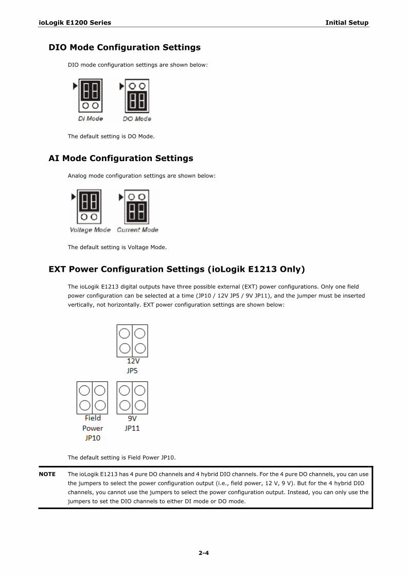
DIO Mode Configuration Settings
DIO mode configuration settings are shown below:
The default setting is DO Mode.
AI Mode Configuration Settings
Analog mode configuration settings are shown below:
The default setting is Voltage Mode.
EXT Power Configuration Settings (ioLogik E1213 Only)
The ioLogik E1213 digital outputs have three possible external (EXT) power configurations. Only one field power configuration can be selected at a time (JP10 / 12V JP5 / 9V JP11), and the jumper must be inserted vertically, not horizontally. EXT power configuration settings are shown below:
The default setting is Field Power JP10.
NOTE The ioLogik E1213 has 4 pure DO channels and 4 hybrid DIO channels. For the 4 pure DO channels, you can use the jumpers to select the power configuration output (i.e., field power, 12 V, 9 V). But for the 4 hybrid DIO channels, you cannot use the jumpers to select the power configuration output. Instead, you can only use the jumpers to set the DIO channels to either DI mode or DO mode.
ioLogik E1200 Series Initial Setup
2-5
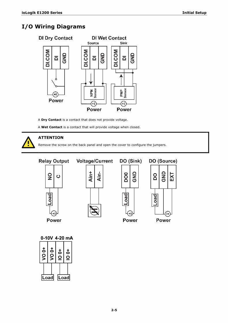
I/O Wiring Diagrams
A Dry Contact is a contact that does not provide voltage.
A Wet Contact is a contact that will provide voltage when closed.
ATTENTION
Remove the screw on the back panel and open the cover to configure the jumpers.
ioLogik E1200 Series Initial Setup
2-6
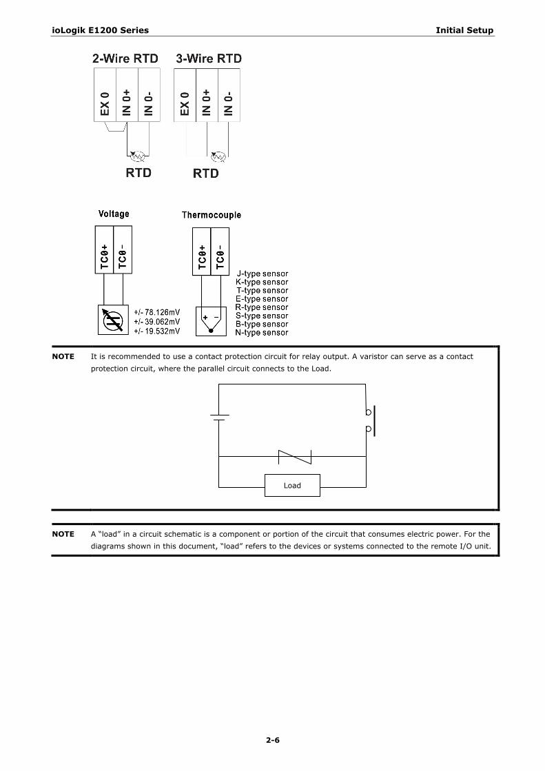
NOTE It is recommended to use a contact protection circuit for relay output. A varistor can serve as a contact protection circuit, where the parallel circuit connects to the Load.
NOTE A “load” in a circuit schematic is a component or portion of the circuit that consumes electric power. For the diagrams shown in this document, “load” refers to the devices or systems connected to the remote I/O unit.
Load
ioLogik E1200 Series Initial Setup
2-7
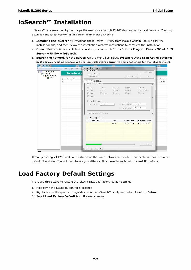
ioSearch™ Installation ioSearch™ is a search utility that helps the user locate ioLogik E1200 devices on the local network. You may download the latest version of ioSearch™ from Moxa’s website.
1. Installing the ioSearch™: Download the ioSearch™ utility from Moxa’s website, double click the installation file, and then follow the installation wizard’s instructions to complete the installation.
2. Open ioSearch: After installation is finished, run ioSearch™ from Start Program Files MOXA IO Server Utility ioSearch.
3. Search the network for the server: On the menu bar, select System Auto Scan Active Ethernet I/O Server. A dialog window will pop up. Click Start Search to begin searching for the ioLogik E1200.
If multiple ioLogik E1200 units are installed on the same network, remember that each unit has the same default IP address. You will need to assign a different IP address to each unit to avoid IP conflicts.
Load Factory Default Settings There are three ways to restore the ioLogik E1200 to factory default settings.
1. Hold down the RESET button for 5 seconds 2. Right-click on the specific ioLogik device in the ioSearch™ utility and select Reset to Default 3. Select Load Factory Default from the web console
3 3. Using the Web Console
The ioLogik E1200’s main configuration and management utility is the built-in web console, which can be used to configure a wide range of options.
The following topics are covered in this chapter:
Introduction to the Web Console
Overview
Network Settings for the Web Console
General Settings
Ethernet Configuration
User-Defined Modbus Addressing
Default Modbus Address
AOPC Server Settings
Tag Generation
I/O Settings
DI Channels
DO Channels
AI Channels
AI Input Range
AO Channels
RTD Channels
TC Channels
Peer-to-Peer Networking
Peer-to-Peer Settings (1-50)
Sample Peer-to-Peer Configuration
DO Safe Mode Settings
AO Safe Mode Settings
SNMP
SNMP Trap
Using SNMP
Accessibility IP List
RESTful API Setting
EtherNet/IP Setting
System Management
Network Connection
Firmware Update
Import System Configuration Settings
Export System Settings
Change Password
Load Factory Defaults
Save/Restart

ioLogik E1200 Series Using the Web Console
3-2
Introduction to the Web Console The ioLogik E1200 web console is a browser-based configuration utility. When the ioLogik E1200 is connected to your network, you may enter the server’s IP address in your web browser to access the web console.
The left panel is the navigation panel and contains an expandable menu tree for navigating among the various settings and categories. When you click on a menu item in the navigation panel, the main window will display the corresponding options for that item. Configuration changes can then be made in the main window. For example, if you click on Network Settings in the navigation panel, the main window will show a page of basic settings that you can configure.
You must click on the Submit button after making configuration changes. The Submit button will be located at the bottom of every page that has configurable settings. If you navigate to another page without clicking the Submit button, your changes will not be retained.
Submitted changes will not take effect until they are saved and the ioLogik E1200 is restarted! You may save and restart the server in one step by clicking on the Save/Restart button after you submit a change. If you need to make several changes before restarting, you may save your changes without restarting by selecting Save/Restart in the navigation panel. If you restart the ioLogik E1200 without saving your configuration, the ioLogik E1200 will discard all submitted changes.
NOTE The web console is best viewed with Internet Explorer 9 or higher; some functionality may not be supported when using other browsers.
ioLogik E1200 Series Using the Web Console
3-3
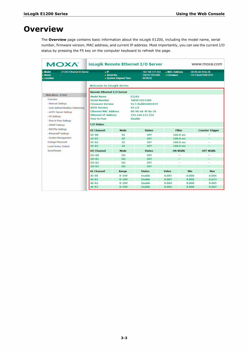
Overview The Overview page contains basic information about the ioLogik E1200, including the model name, serial number, firmware version, MAC address, and current IP address. Most importantly, you can see the current I/O status by pressing the F5 key on the computer keyboard to refresh the page.
ioLogik E1200 Series Using the Web Console
3-4
Network Settings for the Web Console
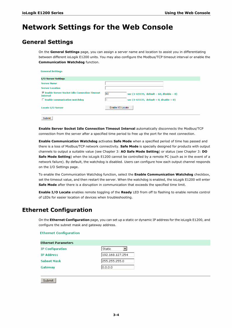
General Settings On the General Settings page, you can assign a server name and location to assist you in differentiating between different ioLogik E1200 units. You may also configure the Modbus/TCP timeout interval or enable the Communication Watchdog function.
Enable Server Socket Idle Connection Timeout Interval automatically disconnects the Modbus/TCP connection from the server after a specified time period to free up the port for the next connection.
Enable Communication Watchdog activates Safe Mode when a specified period of time has passed and there is a loss of Modbus/TCP network connectivity. Safe Mode is specially designed for products with output channels to output a suitable value (see Chapter 3: AO Safe Mode Setting) or status (see Chapter 3: DO Safe Mode Setting) when the ioLogik E1200 cannot be controlled by a remote PC (such as in the event of a network failure). By default, the watchdog is disabled. Users can configure how each output channel responds on the I/O Settings page.
To enable the Communication Watchdog function, select the Enable Communication Watchdog checkbox, set the timeout value, and then restart the server. When the watchdog is enabled, the ioLogik E1200 will enter Safe Mode after there is a disruption in communication that exceeds the specified time limit.
Enable I/O Locate enables remote toggling of the Ready LED from off to flashing to enable remote control of LEDs for easier location of devices when troubleshooting.
Ethernet Configuration On the Ethernet Configuration page, you can set up a static or dynamic IP address for the ioLogik E1200, and configure the subnet mask and gateway address.
ioLogik E1200 Series Using the Web Console
3-5
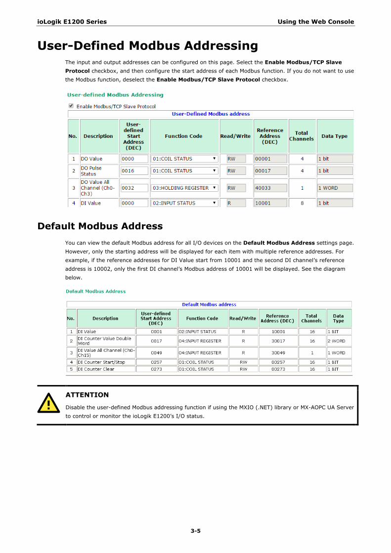
User-Defined Modbus Addressing The input and output addresses can be configured on this page. Select the Enable Modbus/TCP Slave Protocol checkbox, and then configure the start address of each Modbus function. If you do not want to use the Modbus function, deselect the Enable Modbus/TCP Slave Protocol checkbox.
Default Modbus Address You can view the default Modbus address for all I/O devices on the Default Modbus Address settings page. However, only the starting address will be displayed for each item with multiple reference addresses. For example, if the reference addresses for DI Value start from 10001 and the second DI channel’s reference address is 10002, only the first DI channel’s Modbus address of 10001 will be displayed. See the diagram below.
ATTENTION
Disable the user-defined Modbus addressing function if using the MXIO (.NET) library or MX-AOPC UA Server to control or monitor the ioLogik E1200’s I/O status.
ioLogik E1200 Series Using the Web Console
3-6
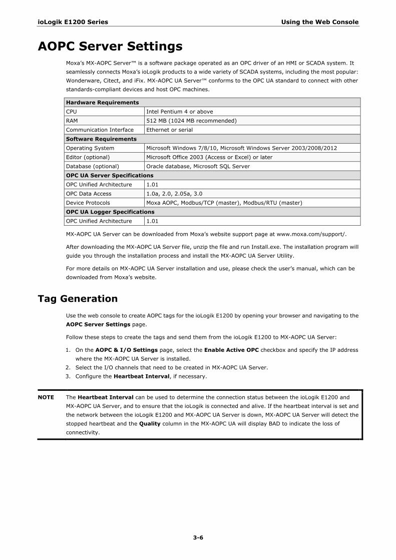
AOPC Server Settings Moxa’s MX-AOPC Server™ is a software package operated as an OPC driver of an HMI or SCADA system. It seamlessly connects Moxa’s ioLogik products to a wide variety of SCADA systems, including the most popular: Wonderware, Citect, and iFix. MX-AOPC UA Server™ conforms to the OPC UA standard to connect with other standards-compliant devices and host OPC machines.
Hardware Requirements
CPU Intel Pentium 4 or above
RAM 512 MB (1024 MB recommended)
Communication Interface Ethernet or serial
Software Requirements Operating System Microsoft Windows 7/8/10, Microsoft Windows Server 2003/2008/2012
Editor (optional) Microsoft Office 2003 (Access or Excel) or later
Database (optional) Oracle database, Microsoft SQL Server
OPC UA Server Specifications OPC Unified Architecture 1.01
OPC Data Access 1.0a, 2.0, 2.05a, 3.0
Device Protocols Moxa AOPC, Modbus/TCP (master), Modbus/RTU (master)
OPC UA Logger Specifications
OPC Unified Architecture 1.01
MX-AOPC UA Server can be downloaded from Moxa’s website support page at www.moxa.com/support/.
After downloading the MX-AOPC UA Server file, unzip the file and run Install.exe. The installation program will guide you through the installation process and install the MX-AOPC UA Server Utility.
For more details on MX-AOPC UA Server installation and use, please check the user’s manual, which can be downloaded from Moxa’s website.
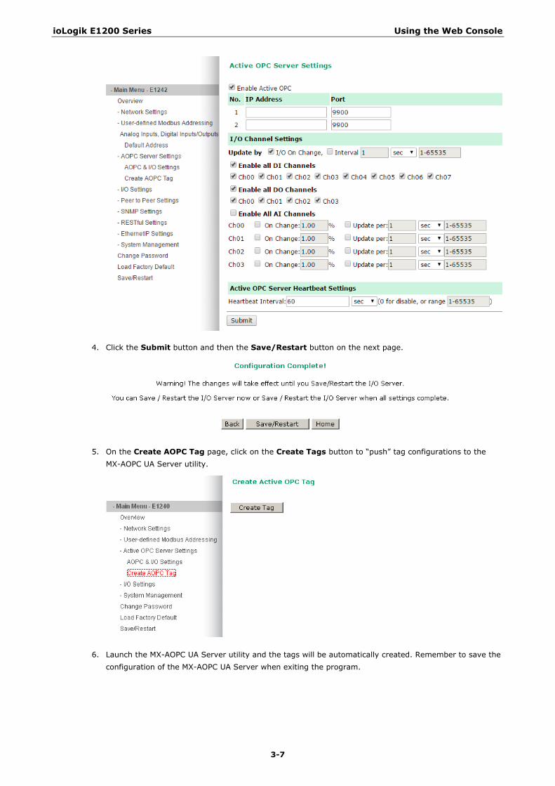
Tag Generation Use the web console to create AOPC tags for the ioLogik E1200 by opening your browser and navigating to the AOPC Server Settings page.
Follow these steps to create the tags and send them from the ioLogik E1200 to MX-AOPC UA Server:
1. On the AOPC & I/O Settings page, select the Enable Active OPC checkbox and specify the IP address where the MX-AOPC UA Server is installed.
2. Select the I/O channels that need to be created in MX-AOPC UA Server. 3. Configure the Heartbeat Interval, if necessary.
NOTE The Heartbeat Interval can be used to determine the connection status between the ioLogik E1200 and MX-AOPC UA Server, and to ensure that the ioLogik is connected and alive. If the heartbeat interval is set and the network between the ioLogik E1200 and MX-AOPC UA Server is down, MX-AOPC UA Server will detect the stopped heartbeat and the Quality column in the MX-AOPC UA will display BAD to indicate the loss of connectivity.
ioLogik E1200 Series Using the Web Console
3-7
4. Click the Submit button and then the Save/Restart button on the next page.
5. On the Create AOPC Tag page, click on the Create Tags button to “push” tag configurations to the MX-AOPC UA Server utility.
6. Launch the MX-AOPC UA Server utility and the tags will be automatically created. Remember to save the configuration of the MX-AOPC UA Server when exiting the program.
ioLogik E1200 Series Using the Web Console
3-8
I/O Settings
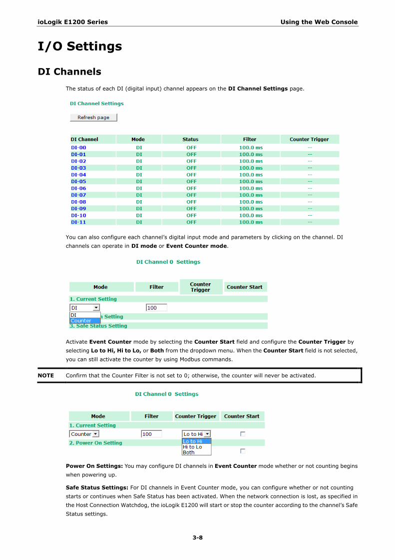
DI Channels The status of each DI (digital input) channel appears on the DI Channel Settings page.
You can also configure each channel’s digital input mode and parameters by clicking on the channel. DI channels can operate in DI mode or Event Counter mode.
Activate Event Counter mode by selecting the Counter Start field and configure the Counter Trigger by selecting Lo to Hi, Hi to Lo, or Both from the dropdown menu. When the Counter Start field is not selected, you can still activate the counter by using Modbus commands.
NOTE Confirm that the Counter Filter is not set to 0; otherwise, the counter will never be activated.
Power On Settings: You may configure DI channels in Event Counter mode whether or not counting begins when powering up.
Safe Status Settings: For DI channels in Event Counter mode, you can configure whether or not counting starts or continues when Safe Status has been activated. When the network connection is lost, as specified in the Host Connection Watchdog, the ioLogik E1200 will start or stop the counter according to the channel’s Safe Status settings.
ioLogik E1200 Series Using the Web Console
3-9
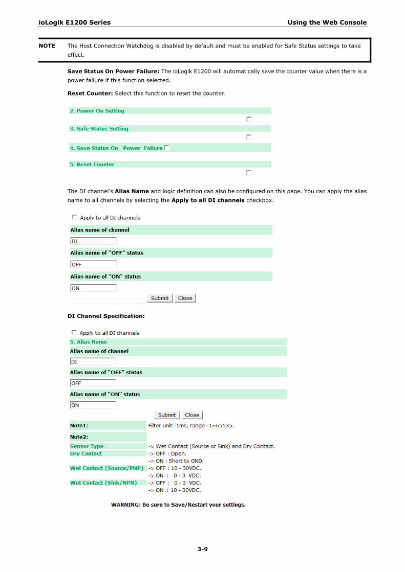
NOTE The Host Connection Watchdog is disabled by default and must be enabled for Safe Status settings to take effect.
Save Status On Power Failure: The ioLogik E1200 will automatically save the counter value when there is a power failure if this function selected.
Reset Counter: Select this function to reset the counter.
The DI channel’s Alias Name and logic definition can also be configured on this page. You can apply the alias name to all channels by selecting the Apply to all DI channels checkbox.
DI Channel Specification:
ioLogik E1200 Series Using the Web Console
3-10
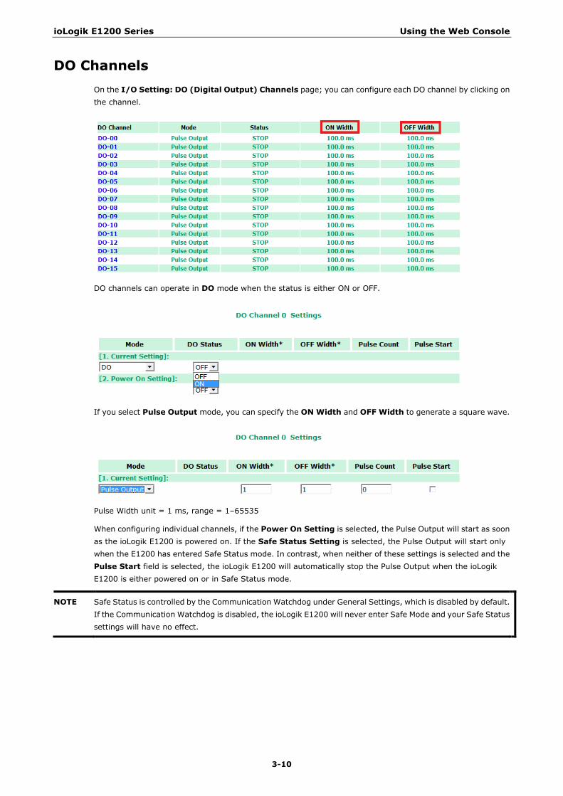
DO Channels On the I/O Setting: DO (Digital Output) Channels page; you can configure each DO channel by clicking on the channel.
DO channels can operate in DO mode when the status is either ON or OFF.
If you select Pulse Output mode, you can specify the ON Width and OFF Width to generate a square wave.
Pulse Width unit = 1 ms, range = 1–65535
When configuring individual channels, if the Power On Setting is selected, the Pulse Output will start as soon as the ioLogik E1200 is powered on. If the Safe Status Setting is selected, the Pulse Output will start only when the E1200 has entered Safe Status mode. In contrast, when neither of these settings is selected and the Pulse Start field is selected, the ioLogik E1200 will automatically stop the Pulse Output when the ioLogik E1200 is either powered on or in Safe Status mode.
NOTE Safe Status is controlled by the Communication Watchdog under General Settings, which is disabled by default. If the Communication Watchdog is disabled, the ioLogik E1200 will never enter Safe Mode and your Safe Status settings will have no effect.
ioLogik E1200 Series Using the Web Console
3-11
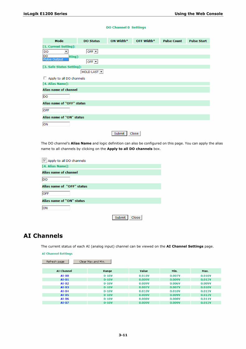
The DO channel’s Alias Name and logic definition can also be configured on this page. You can apply the alias name to all channels by clicking on the Apply to all DO channels box.
AI Channels The current status of each AI (analog input) channel can be viewed on the AI Channel Settings page.
ioLogik E1200 Series Using the Web Console
3-12
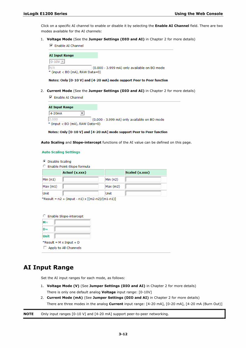
Click on a specific AI channel to enable or disable it by selecting the Enable AI Channel field. There are two modes available for the AI channels:
1. Voltage Mode (See the Jumper Settings (DIO and AI) in Chapter 2 for more details)
2. Current Mode (See the Jumper Settings (DIO and AI) in Chapter 2 for more details)
Auto Scaling and Slope-intercept functions of the AI value can be defined on this page.
AI Input Range Set the AI input ranges for each mode, as follows:
1. Voltage Mode (V) (See Jumper Settings (DIO and AI) in Chapter 2 for more details)
There is only one default analog Voltage input range: [0-10V] 2. Current Mode (mA) (See Jumper Settings (DIO and AI) in Chapter 2 for more details)
There are three modes in the analog Current input range: [4-20 mA], [0-20 mA], [4-20 mA (Burn Out)]
NOTE Only input ranges [0-10 V] and [4-20 mA] support peer-to-peer networking.
ioLogik E1200 Series Using the Web Console
3-13
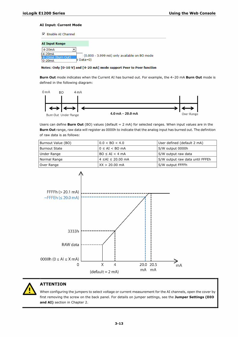
AI Input: Current Mode
Burn Out mode indicates when the Current AI has burned out. For example, the 4–20 mA Burn Out mode is defined in the following diagram:
Users can define Burn Out (BO) values (default = 2 mA) for selected ranges. When input values are in the Burn Out range, raw data will register as 0000h to indicate that the analog input has burned out. The definition of raw data is as follows:
Burnout Value (BO) 0.0 < BO < 4.0 User defined (default 2 mA)
Burnout State 0 ≤ AI < BO mA S/W output 0000h
Under Range BO ≤ AI < 4 mA S/W output raw data
Normal Range 4 ≤AI ≤ 20.00 mA S/W output raw data until FFFEh
Over Range XX > 20.00 mA S/W output FFFFh
ATTENTION
When configuring the jumpers to select voltage or current measurement for the AI channels, open the cover by first removing the screw on the back panel. For details on jumper settings, see the Jumper Settings (DIO and AI) section in Chapter 2.
ioLogik E1200 Series Using the Web Console
3-14
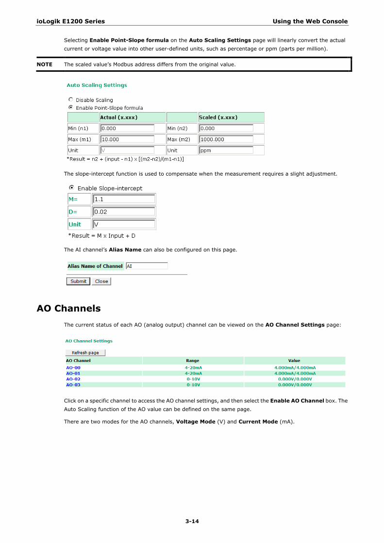
Selecting Enable Point-Slope formula on the Auto Scaling Settings page will linearly convert the actual current or voltage value into other user-defined units, such as percentage or ppm (parts per million).
NOTE The scaled value’s Modbus address differs from the original value.
The slope-intercept function is used to compensate when the measurement requires a slight adjustment.
The AI channel’s Alias Name can also be configured on this page.
AO Channels The current status of each AO (analog output) channel can be viewed on the AO Channel Settings page:
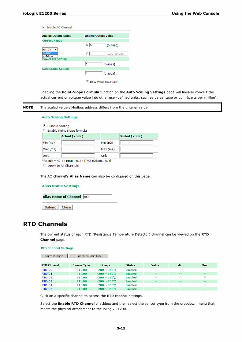
Click on a specific channel to access the AO channel settings, and then select the Enable AO Channel box. The Auto Scaling function of the AO value can be defined on the same page.
There are two modes for the AO channels, Voltage Mode (V) and Current Mode (mA).
ioLogik E1200 Series Using the Web Console
3-15
Enabling the Point-Slope Formula function on the Auto Scaling Settings page will linearly convert the actual current or voltage value into other user-defined units, such as percentage or ppm (parts per million).
NOTE The scaled value’s Modbus address differs from the original value.
The AO channel’s Alias Name can also be configured on this page.
RTD Channels The current status of each RTD (Resistance Temperature Detector) channel can be viewed on the RTD Channel page.
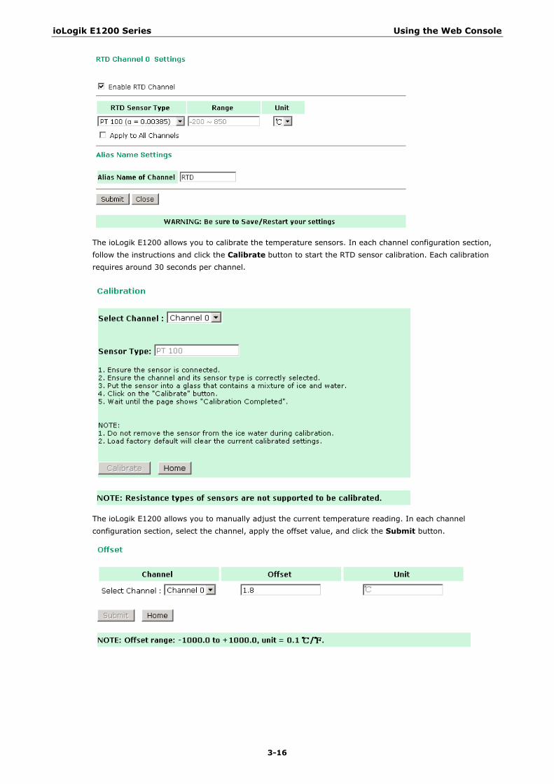
Click on a specific channel to access the RTD channel settings.
Select the Enable RTD Channel checkbox and then select the sensor type from the dropdown menu that meets the physical attachment to the ioLogik E1200.
ioLogik E1200 Series Using the Web Console
3-16
The ioLogik E1200 allows you to calibrate the temperature sensors. In each channel configuration section, follow the instructions and click the Calibrate button to start the RTD sensor calibration. Each calibration requires around 30 seconds per channel.
The ioLogik E1200 allows you to manually adjust the current temperature reading. In each channel configuration section, select the channel, apply the offset value, and click the Submit button.
ioLogik E1200 Series Using the Web Console
3-17
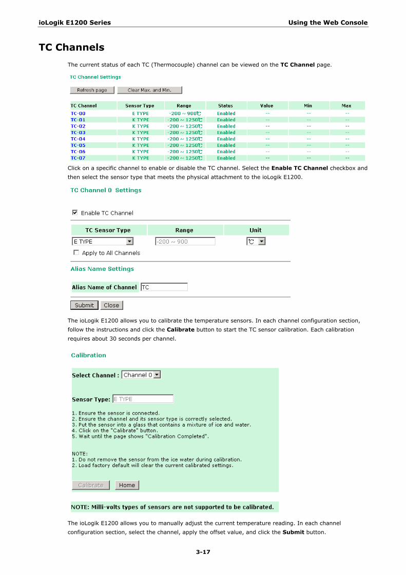
TC Channels The current status of each TC (Thermocouple) channel can be viewed on the TC Channel page.
Click on a specific channel to enable or disable the TC channel. Select the Enable TC Channel checkbox and then select the sensor type that meets the physical attachment to the ioLogik E1200.
The ioLogik E1200 allows you to calibrate the temperature sensors. In each channel configuration section, follow the instructions and click the Calibrate button to start the TC sensor calibration. Each calibration requires about 30 seconds per channel.
The ioLogik E1200 allows you to manually adjust the current temperature reading. In each channel configuration section, select the channel, apply the offset value, and click the Submit button.
ioLogik E1200 Series Using the Web Console
3-18
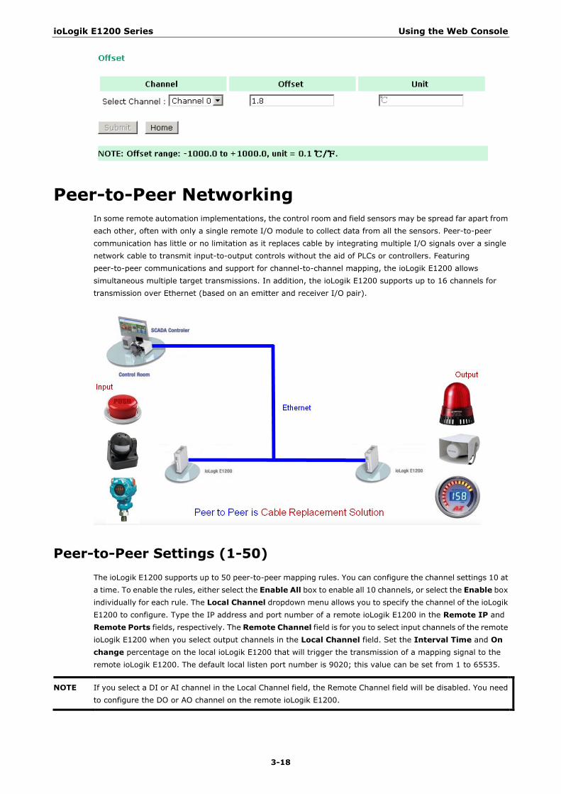
Peer-to-Peer Networking In some remote automation implementations, the control room and field sensors may be spread far apart from each other, often with only a single remote I/O module to collect data from all the sensors. Peer-to-peer communication has little or no limitation as it replaces cable by integrating multiple I/O signals over a single network cable to transmit input-to-output controls without the aid of PLCs or controllers. Featuring peer-to-peer communications and support for channel-to-channel mapping, the ioLogik E1200 allows simultaneous multiple target transmissions. In addition, the ioLogik E1200 supports up to 16 channels for transmission over Ethernet (based on an emitter and receiver I/O pair).
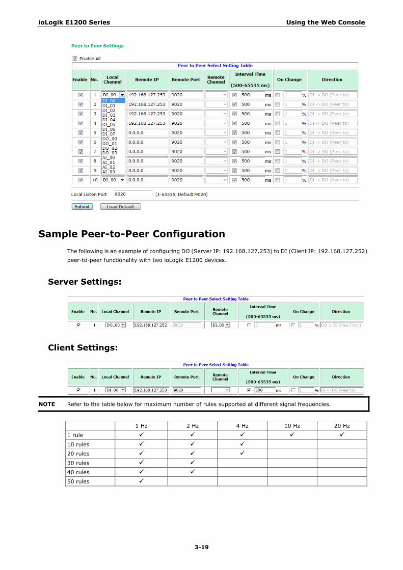
Peer-to-Peer Settings (1-50) The ioLogik E1200 supports up to 50 peer-to-peer mapping rules. You can configure the channel settings 10 at a time. To enable the rules, either select the Enable All box to enable all 10 channels, or select the Enable box individually for each rule. The Local Channel dropdown menu allows you to specify the channel of the ioLogik E1200 to configure. Type the IP address and port number of a remote ioLogik E1200 in the Remote IP and Remote Ports fields, respectively. The Remote Channel field is for you to select input channels of the remote ioLogik E1200 when you select output channels in the Local Channel field. Set the Interval Time and On change percentage on the local ioLogik E1200 that will trigger the transmission of a mapping signal to the remote ioLogik E1200. The default local listen port number is 9020; this value can be set from 1 to 65535.
NOTE If you select a DI or AI channel in the Local Channel field, the Remote Channel field will be disabled. You need to configure the DO or AO channel on the remote ioLogik E1200.
ioLogik E1200 Series Using the Web Console
3-19
Sample Peer-to-Peer Configuration The following is an example of configuring DO (Server IP: 192.168.127.253) to DI (Client IP: 192.168.127.252) peer-to-peer functionality with two ioLogik E1200 devices.
Server Settings:
Client Settings:
NOTE Refer to the table below for maximum number of rules supported at different signal frequencies.
1 Hz 2 Hz 4 Hz 10 Hz 20 Hz
1 rule 10 rules
20 rules
30 rules
40 rules
50 rules
ioLogik E1200 Series Using the Web Console
3-20
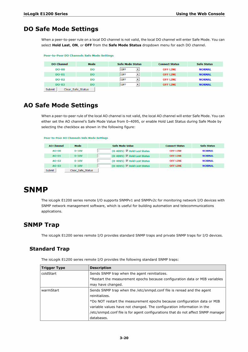
DO Safe Mode Settings When a peer-to-peer rule on a local DO channel is not valid, the local DO channel will enter Safe Mode. You can select Hold Last, ON, or OFF from the Safe Mode Status dropdown menu for each DO channel.
AO Safe Mode Settings When a peer-to-peer rule of the local AO channel is not valid, the local AO channel will enter Safe Mode. You can either set the AO channel’s Safe Mode Value from 0–4095, or enable Hold Last Status during Safe Mode by selecting the checkbox as shown in the following figure:
SNMP The ioLogik E1200 series remote I/O supports SNMPv1 and SNMPv2c for monitoring network I/O devices with SNMP network management software, which is useful for building automation and telecommunications applications.
SNMP Trap The ioLogik E1200 series remote I/O provides standard SNMP traps and private SNMP traps for I/O devices.
Standard Trap
The ioLogik E1200 series remote I/O provides the following standard SNMP traps:
Trigger Type Description
coldStart Sends SNMP trap when the agent reinitializes. *Restart the measurement epochs because configuration data or MIB variables may have changed.
warmStart Sends SNMP trap when the /etc/snmpd.conf file is reread and the agent reinitializes. *Do NOT restart the measurement epochs because configuration data or MIB variable values have not changed. The configuration information in the /etc/snmpd.conf file is for agent configurations that do not affect SNMP manager databases.
ioLogik E1200 Series Using the Web Console
3-21
Private Trap
The ioLogik E1200 series remote I/O provides the following private trap triggers:
Trigger Type Description
DI-change status Sends SNMP trap when DI status changes.
DO-change status Sends SNMP trap when DI status changes.
Relay-change status Sends SNMP trap when Relay status changes.
AI-burn-out Sends SNMP trap when AI reaches preset burn-out value.
AI-trigger Sends SNMP trap when AI reaches preset value.
AO-trigger Sends SNMP trap when AO reaches preset value.
RTD-trigger Sends SNMP trap when RTD reaches preset value.
TC-trigger Sends SNMP trap when TC reaches preset value.
Using SNMP Moxa has provided the ioLogik E1200 MIB file for easier analysis of SNMP data.
SNMP Agent
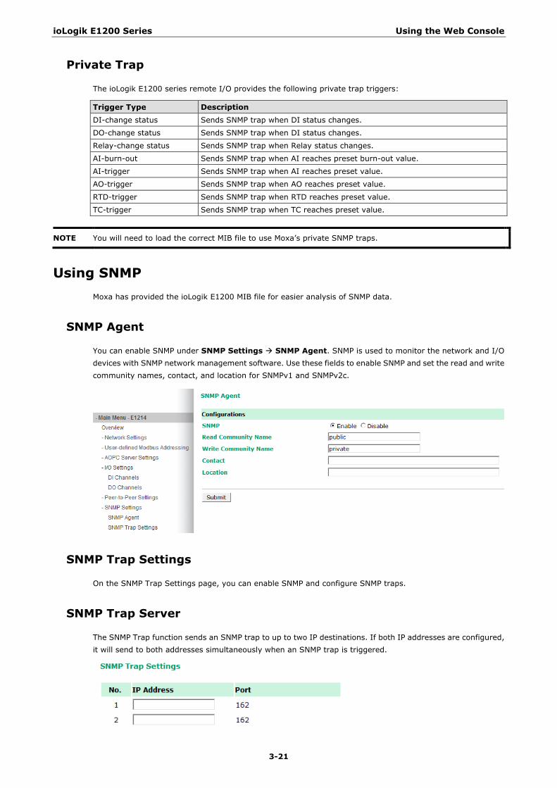
You can enable SNMP under SNMP Settings SNMP Agent. SNMP is used to monitor the network and I/O devices with SNMP network management software. Use these fields to enable SNMP and set the read and write community names, contact, and location for SNMPv1 and SNMPv2c.
SNMP Trap Settings
On the SNMP Trap Settings page, you can enable SNMP and configure SNMP traps.
SNMP Trap Server
The SNMP Trap function sends an SNMP trap to up to two IP destinations. If both IP addresses are configured, it will send to both addresses simultaneously when an SNMP trap is triggered.
NOTE You will need to load the correct MIB file to use Moxa’s private SNMP traps.
ioLogik E1200 Series Using the Web Console
3-22
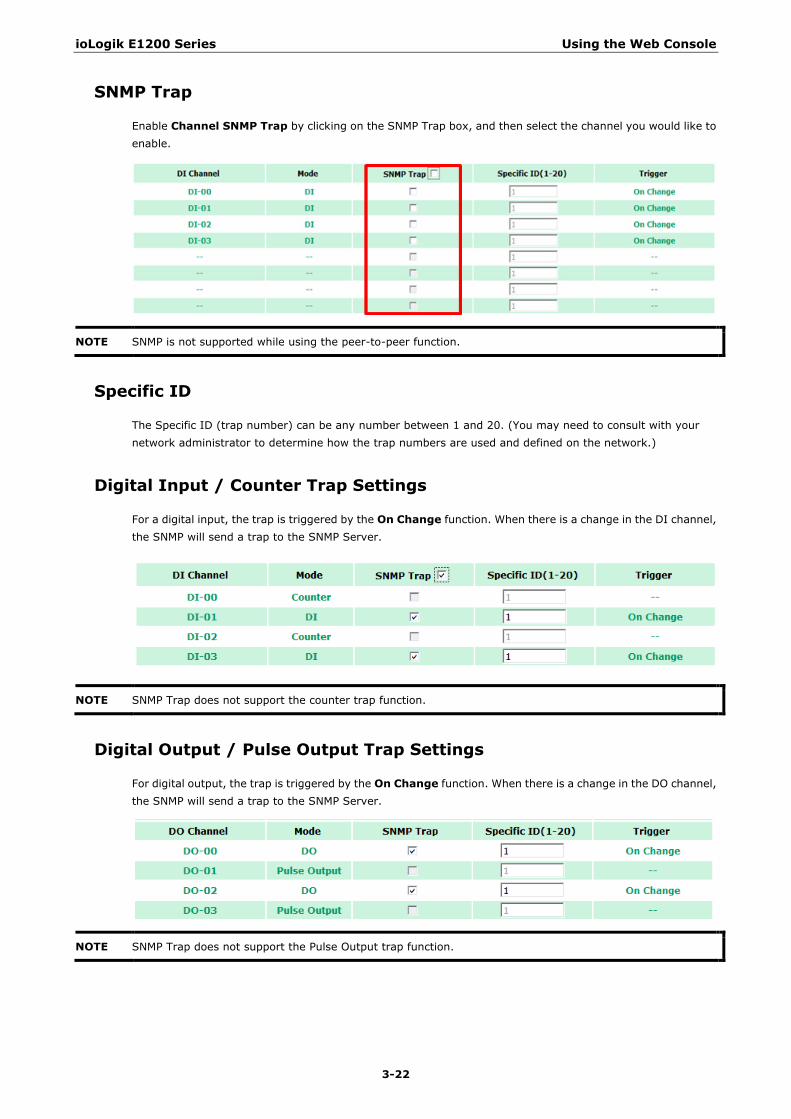
SNMP Trap
Enable Channel SNMP Trap by clicking on the SNMP Trap box, and then select the channel you would like to enable.
NOTE SNMP is not supported while using the peer-to-peer function.
Specific ID
The Specific ID (trap number) can be any number between 1 and 20. (You may need to consult with your network administrator to determine how the trap numbers are used and defined on the network.)
Digital Input / Counter Trap Settings
For a digital input, the trap is triggered by the On Change function. When there is a change in the DI channel, the SNMP will send a trap to the SNMP Server.
NOTE SNMP Trap does not support the counter trap function.
Digital Output / Pulse Output Trap Settings
For digital output, the trap is triggered by the On Change function. When there is a change in the DO channel, the SNMP will send a trap to the SNMP Server.
NOTE SNMP Trap does not support the Pulse Output trap function.

ioLogik E1200 Series Using the Web Console
3-23
Analog Input Trap Settings
For Analog Input, the trap is triggered when an analog input meets the preset conditions for Trigger, Value, and Hysteresis. Refer to the AI Channel settings in Chapter 3 to set the mode.
Example:
For illustration purposes, consider the following example where we set the AI-00 channel’s trigger value to be greater than 5 with a Hysteresis of 1 and also smaller than 5 with a Hysteresis of 1.
When Trigger = Greater, Value = 5, and Hysteresis = 1, the SNMP trap will only be triggered if the analog signal fluctuates from 4 to 5, as depicted in Scenario 1 below. However, if we change the settings to Value = 5 and Hysteresis = 2, the SNMP trap will only be triggered if the analog signal fluctuates from 3 to 5.
When Trigger = Smaller, Value = 5, and Hysteresis = 1, the SNMP trap will only be triggered if the analog signal fluctuates from 6 to 5, as depicted in Scenario 1 below. However, if we change the settings to Value = 5 and Hysteresis = 2, the SNMP trap will only be triggered if the analog signal fluctuates from 7 to 5.
ioLogik E1200 Series Using the Web Console
3-24
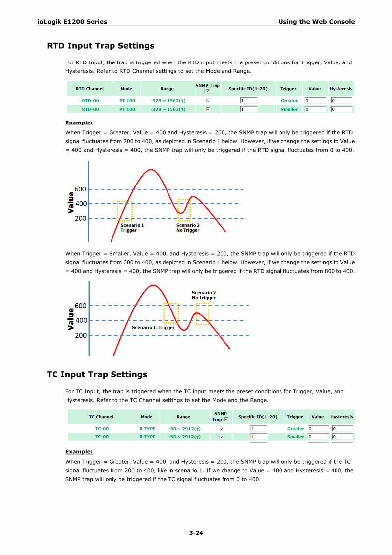
RTD Input Trap Settings
For RTD Input, the trap is triggered when the RTD input meets the preset conditions for Trigger, Value, and Hysteresis. Refer to RTD Channel settings to set the Mode and Range.
Example:
When Trigger = Greater, Value = 400 and Hysteresis = 200, the SNMP trap will only be triggered if the RTD signal fluctuates from 200 to 400, as depicted in Scenario 1 below. However, if we change the settings to Value = 400 and Hysteresis = 400, the SNMP trap will only be triggered if the RTD signal fluctuates from 0 to 400.
When Trigger = Smaller, Value = 400, and Hysteresis = 200, the SNMP trap will only be triggered if the RTD signal fluctuates from 600 to 400, as depicted in Scenario 1 below. However, if we change the settings to Value = 400 and Hysteresis = 400, the SNMP trap will only be triggered if the RTD signal fluctuates from 800 to 400.
TC Input Trap Settings
For TC Input, the trap is triggered when the TC input meets the preset conditions for Trigger, Value, and Hysteresis. Refer to the TC Channel settings to set the Mode and the Range.
Example:
When Trigger = Greater, Value = 400, and Hysteresis = 200, the SNMP trap will only be triggered if the TC signal fluctuates from 200 to 400, like in scenario 1. If we change to Value = 400 and Hysteresis = 400, the SNMP trap will only be triggered if the TC signal fluctuates from 0 to 400.
ioLogik E1200 Series Using the Web Console
3-25
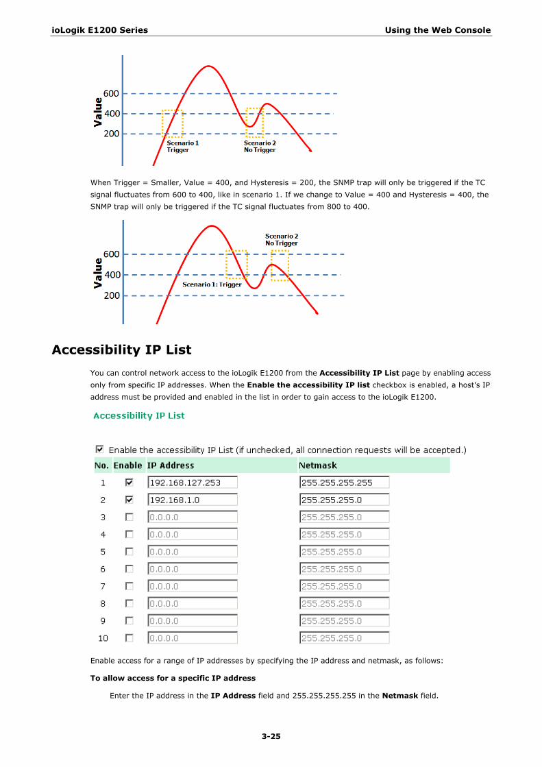
When Trigger = Smaller, Value = 400, and Hysteresis = 200, the SNMP trap will only be triggered if the TC signal fluctuates from 600 to 400, like in scenario 1. If we change to Value = 400 and Hysteresis = 400, the SNMP trap will only be triggered if the TC signal fluctuates from 800 to 400.
Accessibility IP List You can control network access to the ioLogik E1200 from the Accessibility IP List page by enabling access only from specific IP addresses. When the Enable the accessibility IP list checkbox is enabled, a host’s IP address must be provided and enabled in the list in order to gain access to the ioLogik E1200.
Enable access for a range of IP addresses by specifying the IP address and netmask, as follows:
To allow access for a specific IP address
Enter the IP address in the IP Address field and 255.255.255.255 in the Netmask field.
ioLogik E1200 Series Using the Web Console
3-26
To allow access for hosts on a specific subnet
Enter 0 as the last digit in both the IP Address field and Netmask field (e.g., 192.168.1.0 and 255.255.255.0).
To allow unrestricted access
Deselect the Enable the accessible IP list option.
Refer to the following table for additional configuration examples.
Allowed Hosts IP Address/Netmask
Any host Disable
192.168.1.120 192.168.1.120 / 255.255.255.255
192.168.1.1 to 192.168.1.254 192.168.1.0 / 255.255.255.0
192.168.0.1 to 192.168.255.254 192.168.0.0 / 255.255.0.0
192.168.1.1 to 192.168.1.126 192.168.1.0 / 255.255.255.128
192.168.1.129 to 192.168.1.254 192.168.1.128 / 255.255.255.128
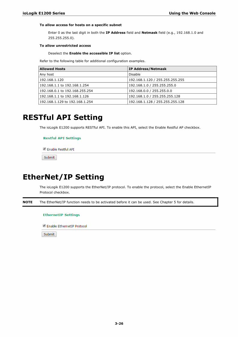
RESTful API Setting The ioLogik E1200 supports RESTful API. To enable this API, select the Enable Restful AP checkbox.
EtherNet/IP Setting The ioLogik E1200 supports the EtherNet/IP protocol. To enable the protocol, select the Enable EthernetIP Protocol checkbox.
NOTE The EtherNet/IP function needs to be activated before it can be used. See Chapter 5 for details.
ioLogik E1200 Series Using the Web Console
3-27
System Management
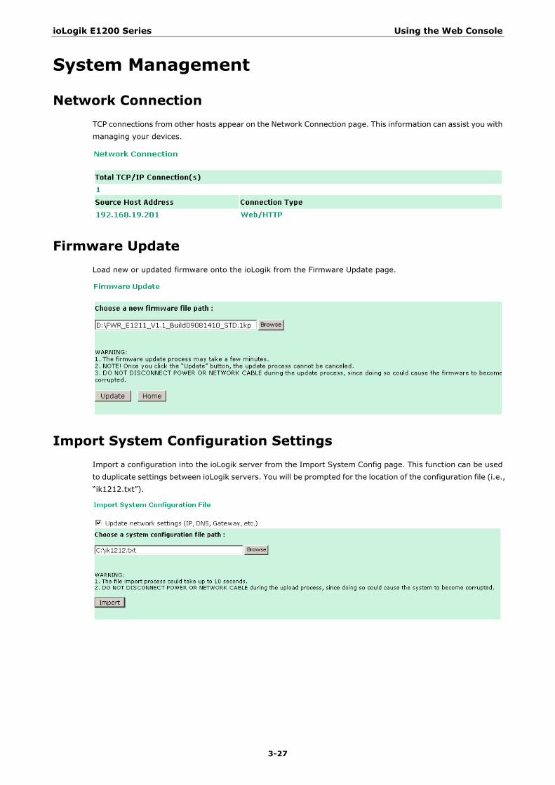
Network Connection TCP connections from other hosts appear on the Network Connection page. This information can assist you with managing your devices.
Firmware Update Load new or updated firmware onto the ioLogik from the Firmware Update page.
Import System Configuration Settings Import a configuration into the ioLogik server from the Import System Config page. This function can be used to duplicate settings between ioLogik servers. You will be prompted for the location of the configuration file (i.e., “ik1212.txt”).
ioLogik E1200 Series Using the Web Console
3-28
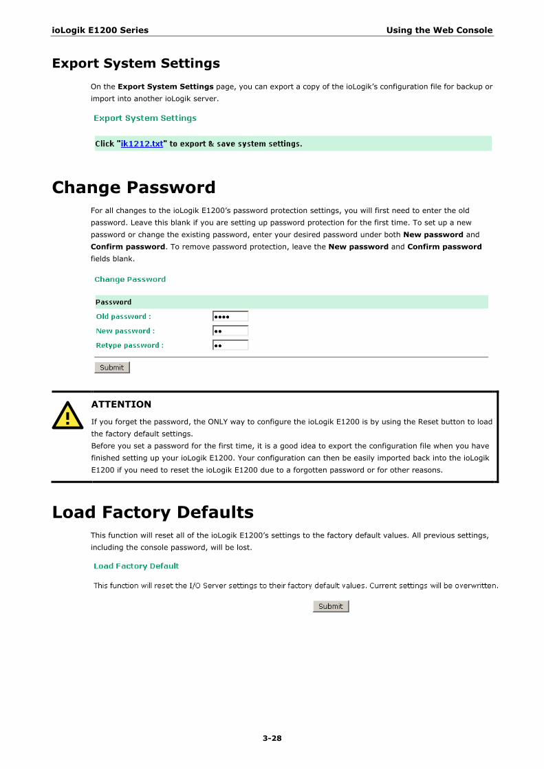
Export System Settings On the Export System Settings page, you can export a copy of the ioLogik’s configuration file for backup or import into another ioLogik server.
Change Password For all changes to the ioLogik E1200’s password protection settings, you will first need to enter the old password. Leave this blank if you are setting up password protection for the first time. To set up a new password or change the existing password, enter your desired password under both New password and Confirm password. To remove password protection, leave the New password and Confirm password fields blank.
ATTENTION
If you forget the password, the ONLY way to configure the ioLogik E1200 is by using the Reset button to load the factory default settings. Before you set a password for the first time, it is a good idea to export the configuration file when you have finished setting up your ioLogik E1200. Your configuration can then be easily imported back into the ioLogik E1200 if you need to reset the ioLogik E1200 due to a forgotten password or for other reasons.
Load Factory Defaults This function will reset all of the ioLogik E1200’s settings to the factory default values. All previous settings, including the console password, will be lost.

ioLogik E1200 Series Using the Web Console
3-29
Save/Restart If you change the configuration, do not forget to reboot the system.
4 4. Using ioSearch™
This chapter describes ioSearch™, which is used to search for and locate ioLogik E1200 units.
The following topics are covered in this chapter:
Introduction to ioSearch™
ioSearch™ Main Screen
Main Screen Overview
ioSearch™ Setup
System
Sort
Quick Links
Main Function
Locate
Firmware Upgrade
Unlock
Import
Export
Change IP Address
Batch TCP/IP Configuration on Multiple Devices
Change Server Name
Activate EtherNet/IP
Restart System
Reset to Default
Mass Deployment (Import)
Mass Deployment (Export)
ioLogik E1200 Series Using ioSearch™
4-2
Introduction to ioSearch™ Moxa’s ioSearch™ utility is software tool that searches for ioLogik E1200 units on a physical network. The following functions are supported by the ioSearch™ utility:
• Search for and locate ioLogik E1200 units • Configure IP addresses • Upgrade firmware for multiple ioLogik E1200 units (same model) • Export configuration files from multiple ioLogik E1200 units • Import configuration files from multiple ioLogik E1200 units (same model) • Reset to default for multiple ioLogik E1200 units • Activate the EtherNet/IP function for multiple ioLogik E1200 units (you will need to register the device
before activating it)
ioSearch™ Main Screen
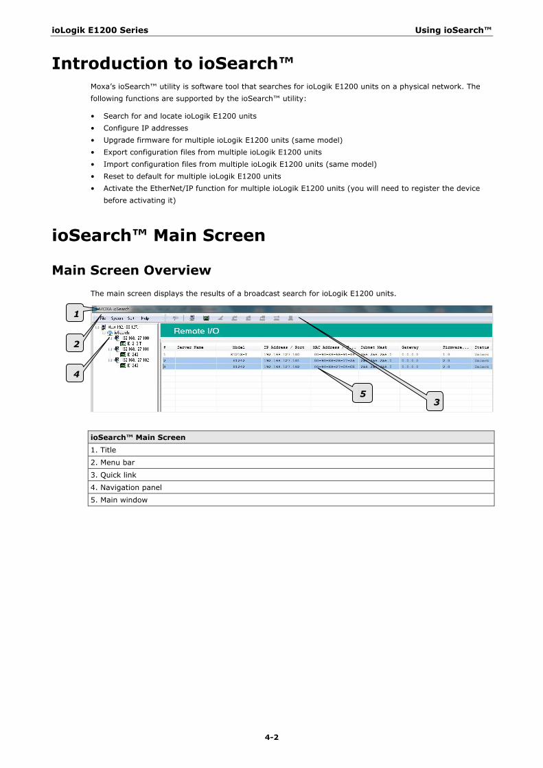
Main Screen Overview The main screen displays the results of a broadcast search for ioLogik E1200 units.
ioSearch™ Main Screen
1. Title
2. Menu bar
3. Quick link
4. Navigation panel
5. Main window
1
2
4
5 3
ioLogik E1200 Series Using ioSearch™
4-3
ioSearch™ Setup
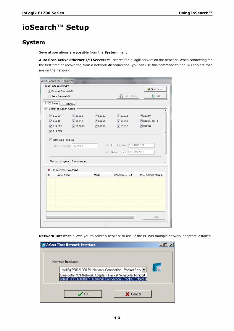
System Several operations are possible from the System menu.
Auto Scan Active Ethernet I/O Servers will search for ioLogik servers on the network. When connecting for the first time or recovering from a network disconnection, you can use this command to find I/O servers that are on the network.
Network Interface allows you to select a network to use, if the PC has multiple network adapters installed.
ioLogik E1200 Series Using ioSearch™
4-4
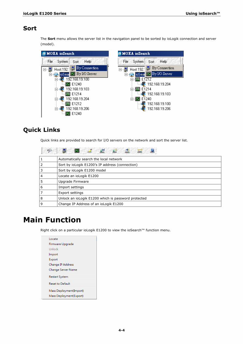
Sort The Sort menu allows the server list in the navigation panel to be sorted by ioLogik connection and server (model).
Quick Links Quick links are provided to search for I/O servers on the network and sort the server list.
1 Automatically search the local network
2 Sort by ioLogik E1200’s IP address (connection)
3 Sort by ioLogik E1200 model
4 Locate an ioLogik E1200
5 Upgrade Firmware
6 Import settings
7 Export settings
8 Unlock an ioLogik E1200 which is password protected
9 Change IP Address of an ioLogik E1200
Main Function Right click on a particular ioLogik E1200 to view the ioSearch™ function menu.
ioLogik E1200 Series Using ioSearch™
4-5
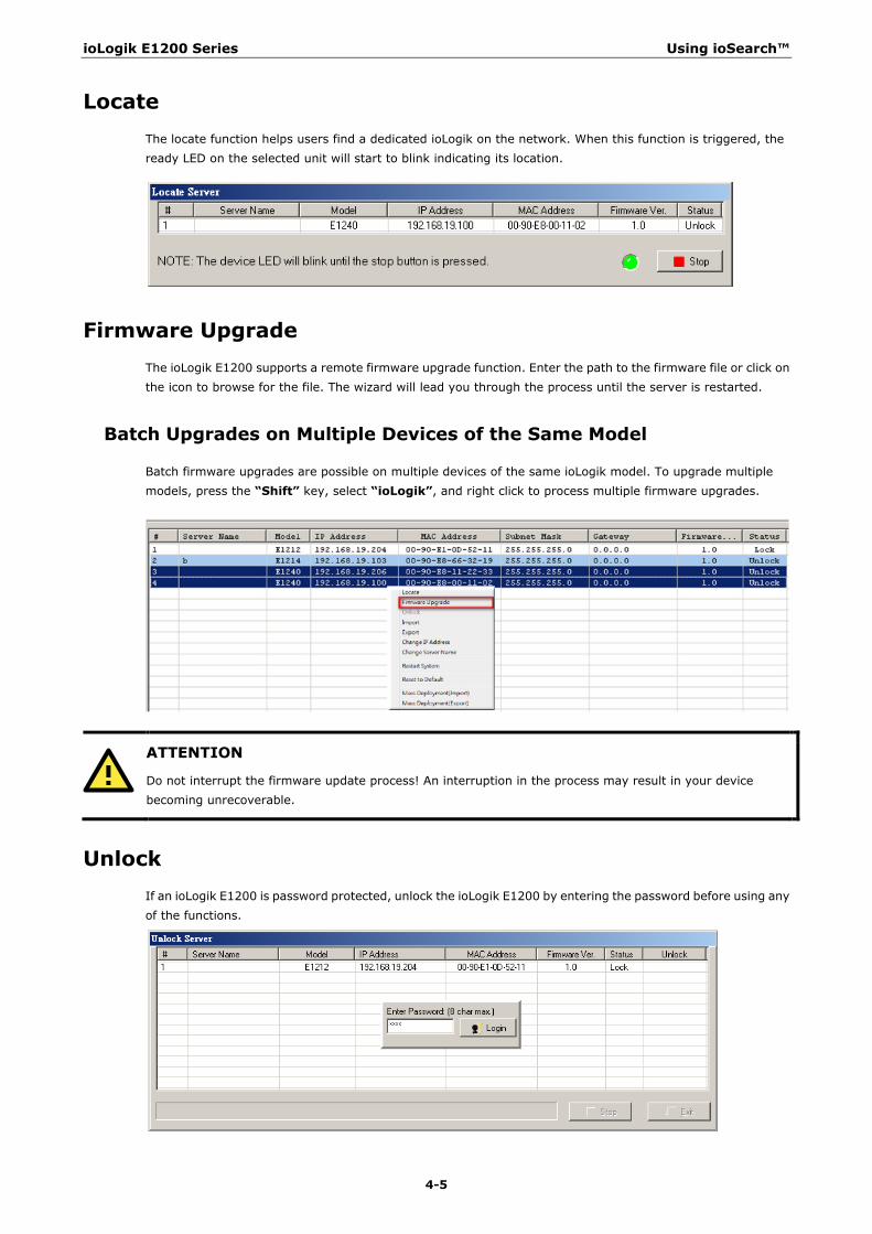
Locate The locate function helps users find a dedicated ioLogik on the network. When this function is triggered, the ready LED on the selected unit will start to blink indicating its location.
Firmware Upgrade The ioLogik E1200 supports a remote firmware upgrade function. Enter the path to the firmware file or click on the icon to browse for the file. The wizard will lead you through the process until the server is restarted.
Batch Upgrades on Multiple Devices of the Same Model
Batch firmware upgrades are possible on multiple devices of the same ioLogik model. To upgrade multiple models, press the “Shift” key, select “ioLogik”, and right click to process multiple firmware upgrades.
ATTENTION
Do not interrupt the firmware update process! An interruption in the process may result in your device becoming unrecoverable.
Unlock If an ioLogik E1200 is password protected, unlock the ioLogik E1200 by entering the password before using any of the functions.
ioLogik E1200 Series Using ioSearch™
4-6
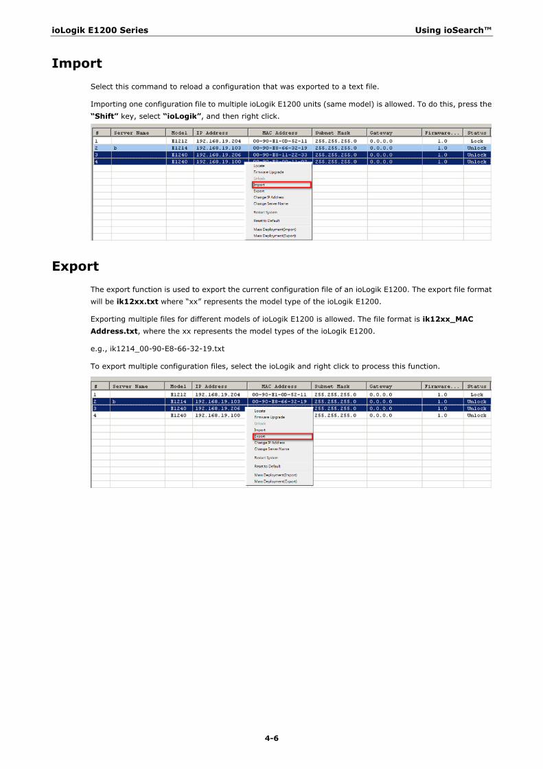
Import Select this command to reload a configuration that was exported to a text file.
Importing one configuration file to multiple ioLogik E1200 units (same model) is allowed. To do this, press the “Shift” key, select “ioLogik”, and then right click.
Export The export function is used to export the current configuration file of an ioLogik E1200. The export file format will be ik12xx.txt where “xx” represents the model type of the ioLogik E1200.
Exporting multiple files for different models of ioLogik E1200 is allowed. The file format is ik12xx_MAC Address.txt, where the xx represents the model types of the ioLogik E1200.
e.g., ik1214_00-90-E8-66-32-19.txt
To export multiple configuration files, select the ioLogik and right click to process this function.
ioLogik E1200 Series Using ioSearch™
4-7
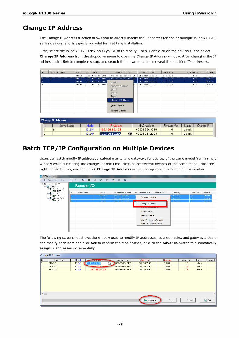
Change IP Address The Change IP Address function allows you to directly modify the IP address for one or multiple ioLogik E1200 series devices, and is especially useful for first time installation.
First, select the ioLogik E1200 device(s) you wish to modify. Then, right-click on the device(s) and select Change IP Address from the dropdown menu to open the Change IP Address window. After changing the IP address, click Set to complete setup, and search the network again to reveal the modified IP addresses.
Batch TCP/IP Configuration on Multiple Devices Users can batch modify IP addresses, subnet masks, and gateways for devices of the same model from a single window while submitting the changes at one time. First, select several devices of the same model, click the right mouse button, and then click Change IP Address in the pop-up menu to launch a new window.
The following screenshot shows the window used to modify IP addresses, subnet masks, and gateways. Users can modify each item and click Set to confirm the modification, or click the Advance button to automatically assign IP addresses incrementally.
ioLogik E1200 Series Using ioSearch™
4-8
After clicking the Advance button, a window will pop up to allow users to use ioSearch™ to set the IP address by MAC address. ioSearch™ will automatically set sequential IP addresses on the selected devices, with the subnet mask and gateway set to the same value.
Change Server Name To change the server name, click on the Change Server Name option, type the name in the Server Name box, and then click Advance.
Activate EtherNet/IP Right click on the device and select Activate EtherNet/IP. The progress of the activation process will be shown onscreen, and ioSearch will inform you when the activation has finished.
NOTE The EtherNet/IP function needs to be activated before it can be used. See Chapter 5 for details.
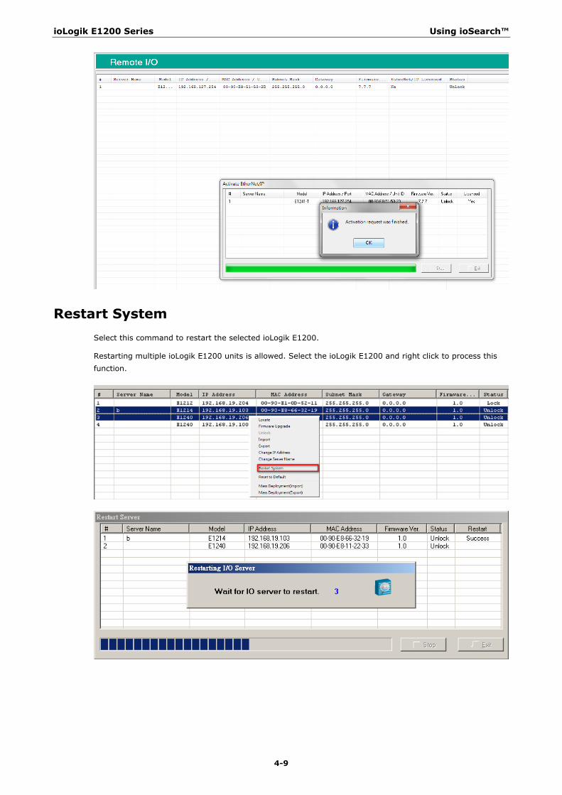
ioLogik E1200 Series Using ioSearch™
4-9
Restart System Select this command to restart the selected ioLogik E1200.
Restarting multiple ioLogik E1200 units is allowed. Select the ioLogik E1200 and right click to process this function.

ioLogik E1200 Series Using ioSearch™
4-10
Reset to Default Select this function to reset all settings, including console password, to factory default values.
Resetting multiple ioLogik E1200 units to the default configuration is allowed. Select the ioLogik E1200 and right click to process this function.
Mass Deployment (Import) Users can import E1200 series module information via ioSearch™. Select this command to reload a configuration from an exported .CSV file.
Mass Deployment (Export) Users can export E1200 series module information via ioSearch™. The export file format will be E1200_Series_List.

5 5. Activation Process for the EtherNet/IP
Function
The ioLogik E1200 series supports the EtherNet/IP protocol once the device has been registered and activated. In this note, we will explain how to activate the EtherNet/IP function in the ioLogik E1200 series. The EtherNet/IP function can only be activated after the following firmware and utility versions are up-to-date.
• ioLogik E1210 V2.5 (std. version) • ioLogik E1211 V2.4 (std. version) • ioLogik E1212 V2.5 (std. version) • ioLogik E1213 V2.6 (std. version) • ioLogik E1214 V2.5 (std. version) • ioLogik E1240 V2.4 (std. version) • ioLogik E1241 V2.5 (std. version) • ioLogik E1242 V2.5 (std. version) • ioLogik E1260 V2.5 (std. version) • ioLogik E1262 V2.5 (std. version) • ioSearch V1.15 (std. version)
Take the following steps to activate the EtherNet/IP function:
Step 1: Assign the license file folder
After installing ioSearch V1.15, the user should assign a folder to place the license file in. Click System Options to find the window displayed below. Next, click the settings icon (shown at the right) to assign the license folder. Click OK to complete the settings.
Settings Icon

ioLogik E1200 Series Activation Process for the EtherNet/IP Function
5-2
Step 2: Get the device’s serial number
Before you start the registration process, locate the serial number on the ioLogik E1200 device. The device’s serial number can be found on the device label, as shown in the picture below.
Step 3: Log in to Moxa’s license server
Moxa’s licensing server can be accessed at the following link: http://license.moxa.com. Input the ID and Password to log in to the system. Click the Apply for an account button to register an account before you login for the first time.

ioLogik E1200 Series Activation Process for the EtherNet/IP Function
5-3
Step 4: Register the device on the Moxa Licensing Server
Click the ioLogik E1200 EtherNet/IP link to go to the registration page. The Moxa Licensing Server provides two ways to complete the registration process. To register a single product, simply input the serial number. To register multiple products, you will need to input serial numbers in a special format. The template for multiple device activation can be downloaded below.
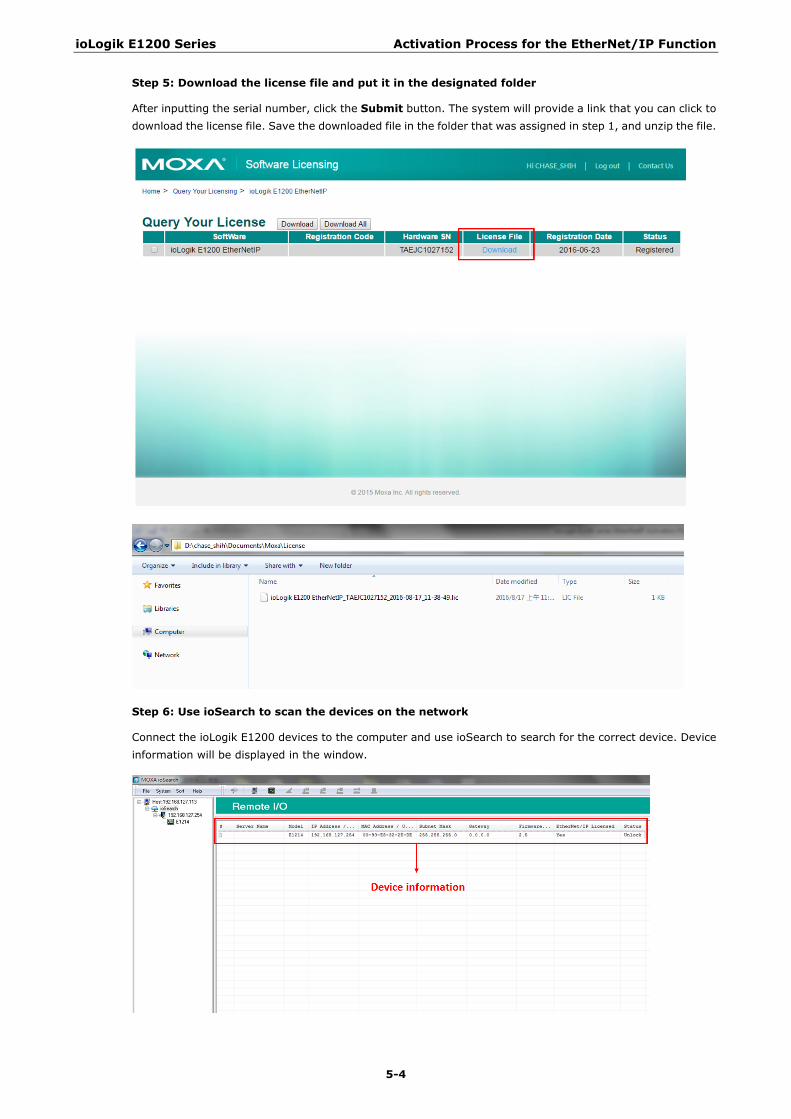
ioLogik E1200 Series Activation Process for the EtherNet/IP Function
5-4
Step 5: Download the license file and put it in the designated folder
After inputting the serial number, click the Submit button. The system will provide a link that you can click to download the license file. Save the downloaded file in the folder that was assigned in step 1, and unzip the file.
Step 6: Use ioSearch to scan the devices on the network
Connect the ioLogik E1200 devices to the computer and use ioSearch to search for the correct device. Device information will be displayed in the window.
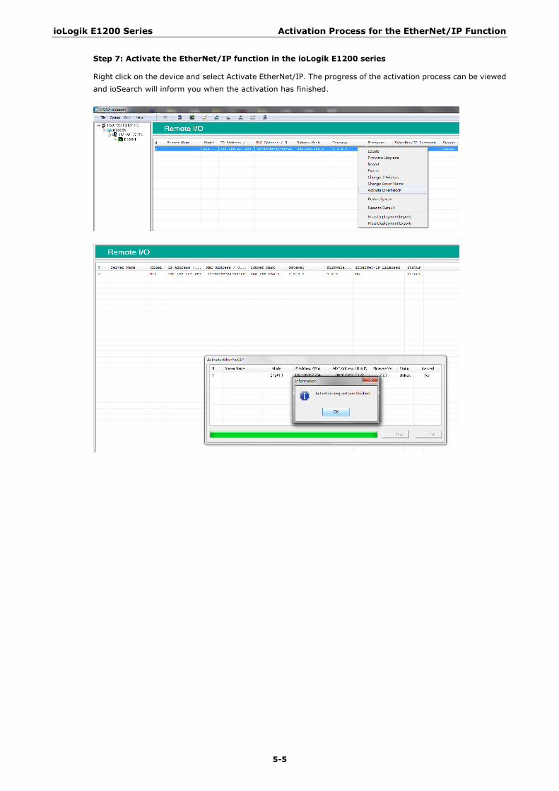
ioLogik E1200 Series Activation Process for the EtherNet/IP Function
5-5
Step 7: Activate the EtherNet/IP function in the ioLogik E1200 series
Right click on the device and select Activate EtherNet/IP. The progress of the activation process can be viewed and ioSearch will inform you when the activation has finished.
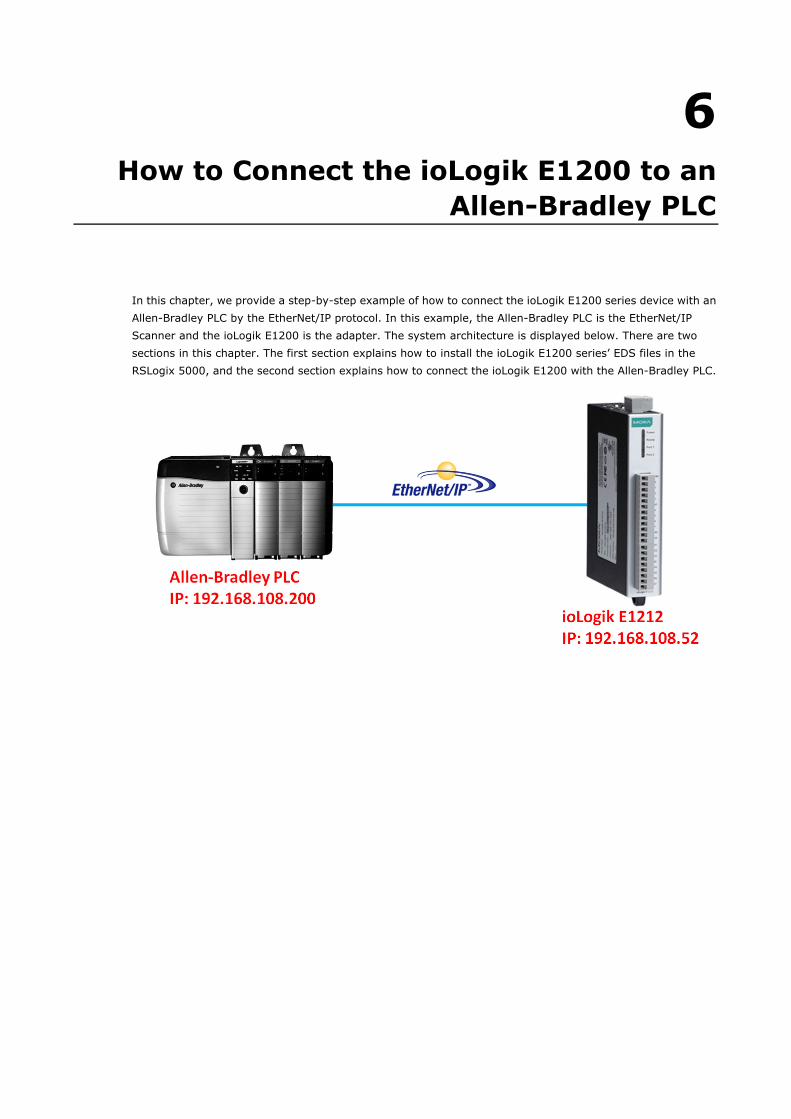
6 6. How to Connect the ioLogik E1200 to an
Allen-Bradley PLC
In this chapter, we provide a step-by-step example of how to connect the ioLogik E1200 series device with an Allen-Bradley PLC by the EtherNet/IP protocol. In this example, the Allen-Bradley PLC is the EtherNet/IP Scanner and the ioLogik E1200 is the adapter. The system architecture is displayed below. There are two sections in this chapter. The first section explains how to install the ioLogik E1200 series’ EDS files in the RSLogix 5000, and the second section explains how to connect the ioLogik E1200 with the Allen-Bradley PLC.
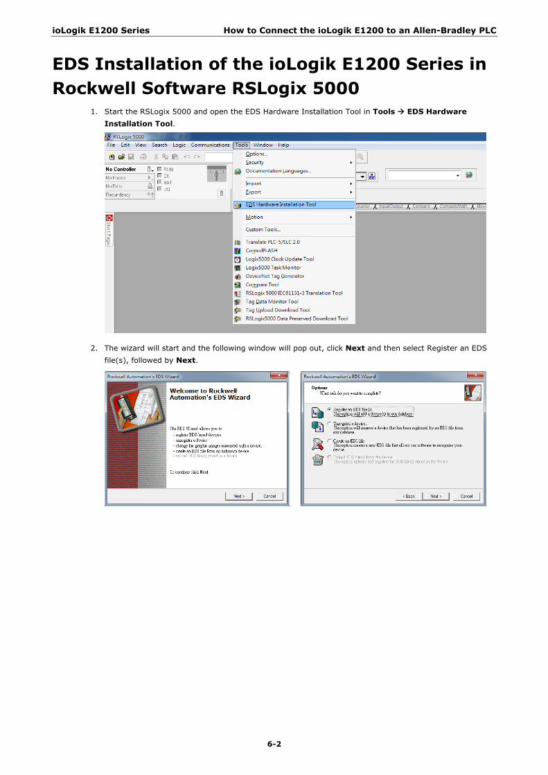
ioLogik E1200 Series How to Connect the ioLogik E1200 to an Allen-Bradley PLC
6-2
EDS Installation of the ioLogik E1200 Series in Rockwell Software RSLogix 5000
1. Start the RSLogix 5000 and open the EDS Hardware Installation Tool in Tools EDS Hardware Installation Tool.
2. The wizard will start and the following window will pop out, click Next and then select Register an EDS file(s), followed by Next.

ioLogik E1200 Series How to Connect the ioLogik E1200 to an Allen-Bradley PLC
6-3
3. There are two ways to register the EDS files. The first is to register a single file, and the second is to register the EDS files by a folder. A. If you want to register one EDS file, select Register a single file and then click Browse.
B. If you want to register several EDS files, put all the EDS files in one folder, select Register a directory of EDS files and then click Browse.
4. Select EDS files and click Open, then it will go back to the wizard. Please click Next to finish the EDS file selection. A. Single EDS file
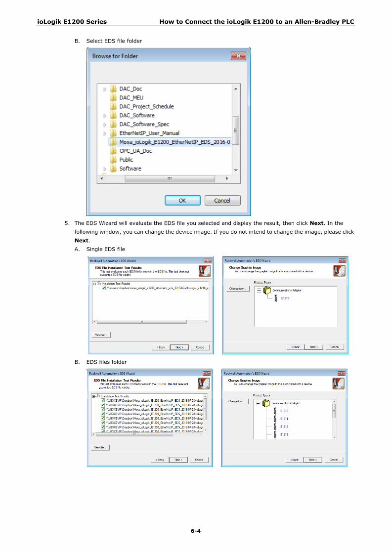
ioLogik E1200 Series How to Connect the ioLogik E1200 to an Allen-Bradley PLC
6-4
B. Select EDS file folder
5. The EDS Wizard will evaluate the EDS file you selected and display the result, then click Next. In the
following window, you can change the device image. If you do not intend to change the image, please click Next. A. Single EDS file
B. EDS files folder
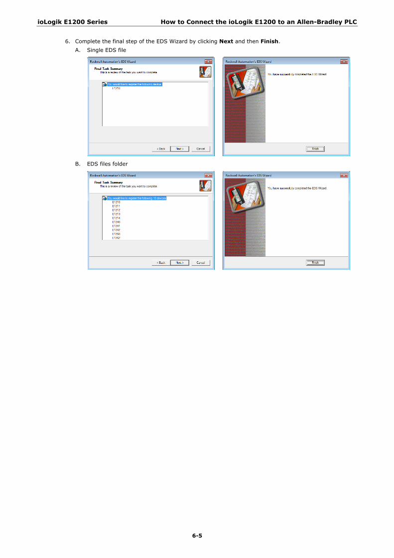
ioLogik E1200 Series How to Connect the ioLogik E1200 to an Allen-Bradley PLC
6-5
6. Complete the final step of the EDS Wizard by clicking Next and then Finish. A. Single EDS file
B. EDS files folder

ioLogik E1200 Series How to Connect the ioLogik E1200 to an Allen-Bradley PLC
6-6
Establishing communication between the ioLogik E1200 device and the Allen-Bradley PLC
1. Open the RSLogix 5000 and then open a new project by pressing File New.
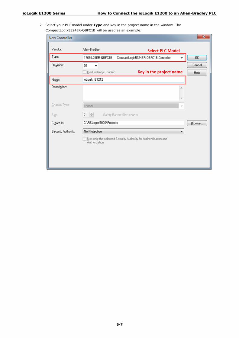
ioLogik E1200 Series How to Connect the ioLogik E1200 to an Allen-Bradley PLC
6-7
2. Select your PLC model under Type and key in the project name in the window. The CompactLogix5324ER-QBFC1B will be used as an example.
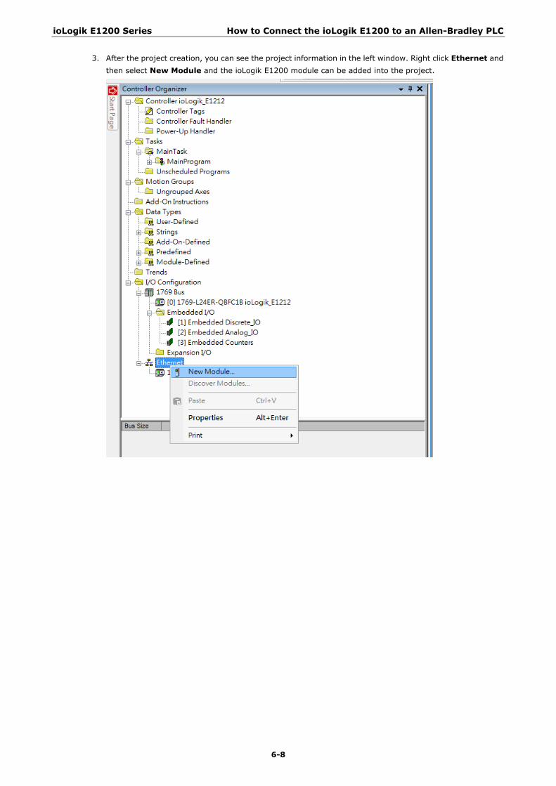
ioLogik E1200 Series How to Connect the ioLogik E1200 to an Allen-Bradley PLC
6-8
3. After the project creation, you can see the project information in the left window. Right click Ethernet and then select New Module and the ioLogik E1200 module can be added into the project.
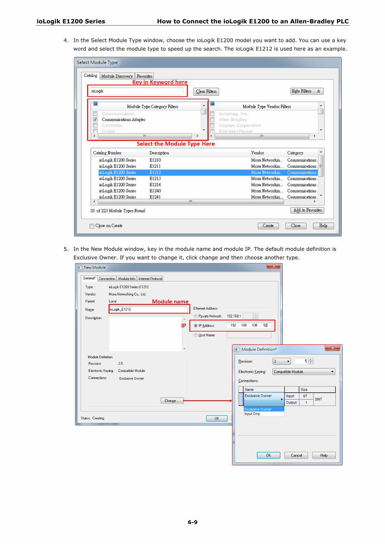
ioLogik E1200 Series How to Connect the ioLogik E1200 to an Allen-Bradley PLC
6-9
4. In the Select Module Type window, choose the ioLogik E1200 model you want to add. You can use a key word and select the module type to speed up the search. The ioLogik E1212 is used here as an example.
5. In the New Module window, key in the module name and module IP. The default module definition is Exclusive Owner. If you want to change it, click change and then choose another type.
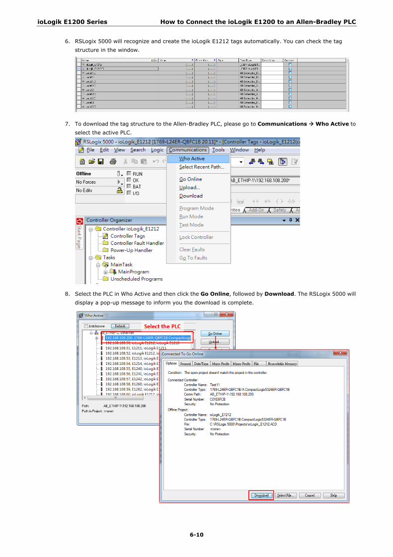
ioLogik E1200 Series How to Connect the ioLogik E1200 to an Allen-Bradley PLC
6-10
6. RSLogix 5000 will recognize and create the ioLogik E1212 tags automatically. You can check the tag structure in the window.
7. To download the tag structure to the Allen-Bradley PLC, please go to Communications Who Active to select the active PLC.
8. Select the PLC in Who Active and then click the Go Online, followed by Download. The RSLogix 5000 will display a pop-up message to inform you the download is complete.
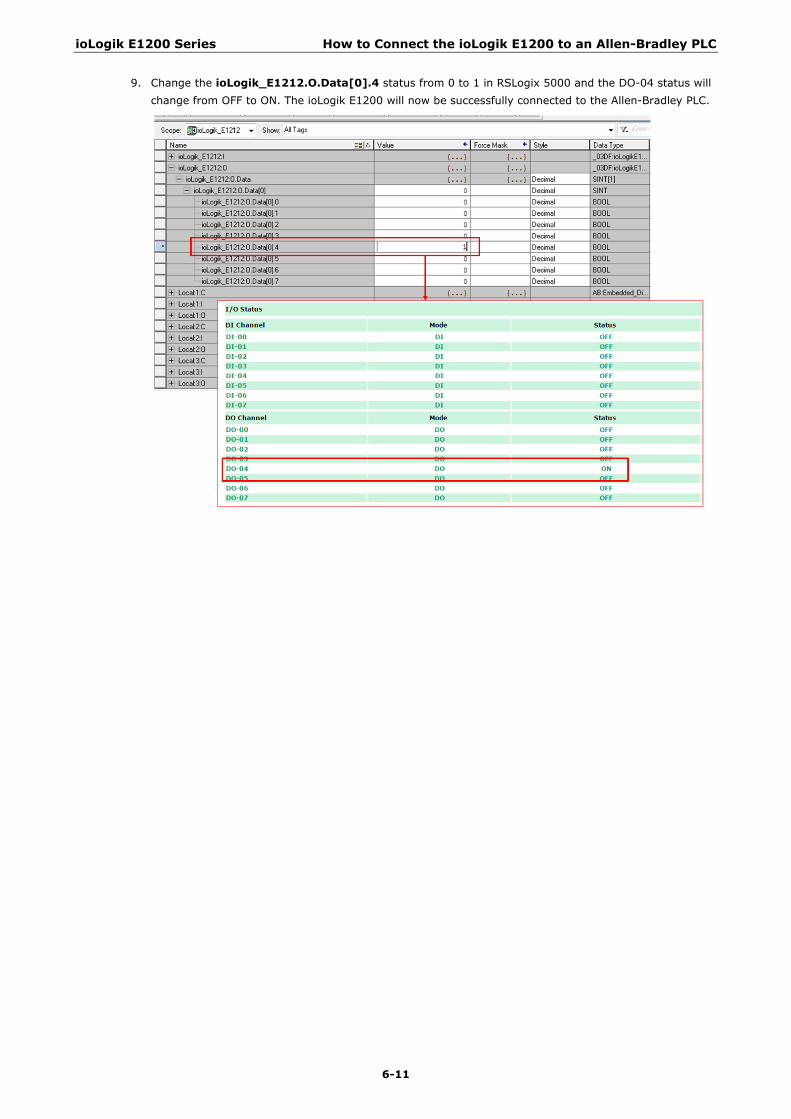
ioLogik E1200 Series How to Connect the ioLogik E1200 to an Allen-Bradley PLC
6-11
9. Change the ioLogik_E1212.O.Data[0].4 status from 0 to 1 in RSLogix 5000 and the DO-04 status will change from OFF to ON. The ioLogik E1200 will now be successfully connected to the Allen-Bradley PLC.
A A. Modbus/TCP Default Address Mappings
The following topics are covered in this appendix:
ioLogik E1210 Modbus Address and Register Map
ioLogik E1211 Modbus Address and Register Map
ioLogik E1212 Modbus Address and Register Map
ioLogik E1213 Modbus Address and Register Map
ioLogik E1214 Modbus Address and Register Map
ioLogik E1240 Modbus Address and Register Map
ioLogik E1241 Modbus Address and Register Map
ioLogik E1242 Modbus Address and Register Map
ioLogik E1260 Modbus Address and Register Map
ioLogik E1262 Modbus Address and Register Map
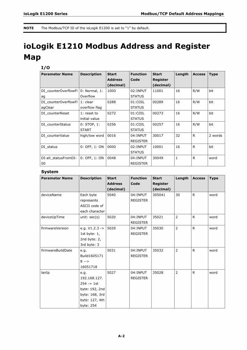
ioLogik E1200 Series Modbus/TCP Default Address Mappings
A-2
NOTE The Modbus/TCP ID of the ioLogik E1200 is set to “1” by default.
ioLogik E1210 Modbus Address and Register Map
I/O Parameter Name Description Start
Address (decimal)
Function Code
Start Register (decimal)
Length Access Type
DI_counterOverflowFlag
0: Normal, 1: Overflow
1000 02:INPUT STATUS
11001 16 R/W bit
DI_counterOverflowFlagClear
1: clear overflow flag
0288 01:COIL STATUS
00289 16 R/W bit
DI_counterReset 1: reset to initial value
0272 01:COIL STATUS
00273 16 R/W bit
DI_counterStatus 0: STOP, 1: START
0256 01:COIL STATUS
00257 16 R/W bit
DI_counterValue high/low word 0016 04:INPUT REGISTER
30017 32 R 2 words
DI_status 0: OFF, 1: ON 0000 02:INPUT STATUS
10001 16 R bit
DI-all_statusFromDI-00
0: OFF, 1: ON 0048 04:INPUT REGISTER
30049 1 R word
System Parameter Name Description Start
Address (decimal)
Function Code
Start Register (decimal)
Length Access Type
deviceName Each byte represents ASCII code of each character
5040 04:INPUT REGISTER
305041 30 R word
deviceUpTime unit: sec(s) 5020 04:INPUT REGISTER
35021 2 R word
firmwareVersion e.g. V1.2.3 -> 1st byte: 1, 2nd byte: 2, 3rd byte: 3
5029 04:INPUT REGISTER
35030 2 R word
firmwareBuildDate e.g. Build16051718 --> 16051718
5031 04:INPUT REGISTER
35032 2 R word
lanIp e.g. 192.168.127.254 -> 1st byte: 192, 2nd byte: 168, 3rd byte: 127, 4th byte: 254
5027 04:INPUT REGISTER
35028 2 R word
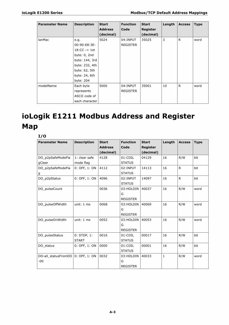
ioLogik E1200 Series Modbus/TCP Default Address Mappings
A-3
Parameter Name Description Start Address (decimal)
Function Code
Start Register (decimal)
Length Access Type
lanMac e.g. 00:90:E8:3E:18:CC -> 1st byte: 0, 2nd byte: 144, 3rd byte: 232, 4th byte: 62, 5th byte: 24, 6th byte: 204
5024 04:INPUT REGISTER
35025 3 R word
modelName Each byte represents ASCII code of each character
5000 04:INPUT REGISTER
35001 10 R word
ioLogik E1211 Modbus Address and Register Map
I/O Parameter Name Description Start
Address (decimal)
Function Code
Start Register (decimal)
Length Access Type
DO_p2pSafeModeFlagClear
1: clear safe mode flag
4128 01:COIL STATUS
04129 16 R/W bit
DO_p2pSafeModeFlag
0: OFF, 1: ON 4112 02:INPUT STATUS
14113 16 R bit
DO_p2pStatus 0: OFF, 1: ON 4096 02:INPUT STATUS
14097 16 R bit
DO_pulseCount 0036 03:HOLDING REGISTER
40037 16 R/W word
DO_pulseOffWidth unit: 1 ms 0068 03:HOLDING REGISTER
40069 16 R/W word
DO_pulseOnWidth unit: 1 ms 0052 03:HOLDING REGISTER
40053 16 R/W word
DO_pulseStatus 0: STOP, 1: START
0016 01:COIL STATUS
00017 16 R/W bit
DO_status 0: OFF, 1: ON 0000 01:COIL STATUS
00001 16 R/W bit
DO-all_statusFromDO-00
0: OFF, 1: ON 0032 03:HOLDING REGISTER
40033 1 R/W word
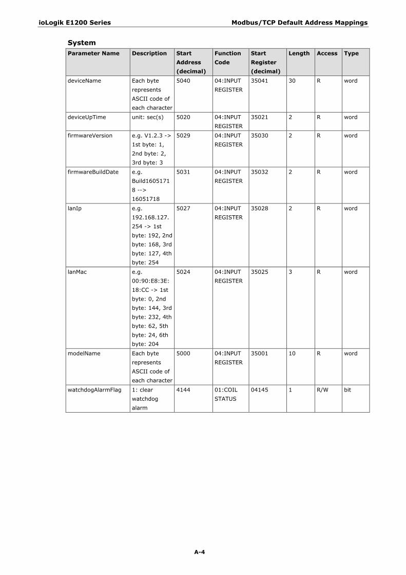
ioLogik E1200 Series Modbus/TCP Default Address Mappings
A-4
System Parameter Name Description Start
Address (decimal)
Function Code
Start Register (decimal)
Length Access Type
deviceName Each byte represents ASCII code of each character
5040 04:INPUT REGISTER
35041 30 R word
deviceUpTime unit: sec(s) 5020 04:INPUT REGISTER
35021 2 R word
firmwareVersion e.g. V1.2.3 -> 1st byte: 1, 2nd byte: 2, 3rd byte: 3
5029 04:INPUT REGISTER
35030 2 R word
firmwareBuildDate e.g. Build16051718 --> 16051718
5031 04:INPUT REGISTER
35032 2 R word
lanIp e.g. 192.168.127.254 -> 1st byte: 192, 2nd byte: 168, 3rd byte: 127, 4th byte: 254
5027 04:INPUT REGISTER
35028 2 R word
lanMac e.g. 00:90:E8:3E:18:CC -> 1st byte: 0, 2nd byte: 144, 3rd byte: 232, 4th byte: 62, 5th byte: 24, 6th byte: 204
5024 04:INPUT REGISTER
35025 3 R word
modelName Each byte represents ASCII code of each character
5000 04:INPUT REGISTER
35001 10 R word
watchdogAlarmFlag 1: clear watchdog alarm
4144 01:COIL STATUS
04145 1 R/W bit
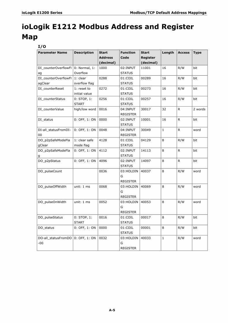
ioLogik E1200 Series Modbus/TCP Default Address Mappings
A-5
ioLogik E1212 Modbus Address and Register Map
I/O Parameter Name Description Start
Address (decimal)
Function Code
Start Register (decimal)
Length Access Type
DI_counterOverflowFlag
0: Normal, 1: Overflow
1000 02:INPUT STATUS
11001 16 R/W bit
DI_counterOverflowFlagClear
1: clear overflow flag
0288 01:COIL STATUS
00289 16 R/W bit
DI_counterReset 1: reset to initial value
0272 01:COIL STATUS
00273 16 R/W bit
DI_counterStatus 0: STOP, 1: START
0256 01:COIL STATUS
00257 16 R/W bit
DI_counterValue high/low word 0016 04:INPUT REGISTER
30017 32 R 2 words
DI_status 0: OFF, 1: ON 0000 02:INPUT STATUS
10001 16 R bit
DI-all_statusFromDI-00
0: OFF, 1: ON 0048 04:INPUT REGISTER
30049 1 R word
DO_p2pSafeModeFlagClear
1: clear safe mode flag
4128 01:COIL STATUS
04129 8 R/W bit
DO_p2pSafeModeFlag
0: OFF, 1: ON 4112 02:INPUT STATUS
14113 8 R bit
DO_p2pStatus 0: OFF, 1: ON 4096 02:INPUT STATUS
14097 8 R bit
DO_pulseCount 0036 03:HOLDING REGISTER
40037 8 R/W word
DO_pulseOffWidth unit: 1 ms 0068 03:HOLDING REGISTER
40069 8 R/W word
DO_pulseOnWidth unit: 1 ms 0052 03:HOLDING REGISTER
40053 8 R/W word
DO_pulseStatus 0: STOP, 1: START
0016 01:COIL STATUS
00017 8 R/W bit
DO_status 0: OFF, 1: ON 0000 01:COIL STATUS
00001 8 R/W bit
DO-all_statusFromDO-00
0: OFF, 1: ON 0032 03:HOLDING REGISTER
40033 1 R/W word
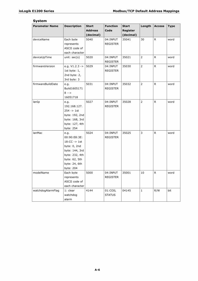
ioLogik E1200 Series Modbus/TCP Default Address Mappings
A-6
System Parameter Name Description Start
Address (decimal)
Function Code
Start Register (decimal)
Length Access Type
deviceName Each byte represents ASCII code of each character
5040 04:INPUT REGISTER
35041 30 R word
deviceUpTime unit: sec(s) 5020 04:INPUT REGISTER
35021 2 R word
firmwareVersion e.g. V1.2.3 -> 1st byte: 1, 2nd byte: 2, 3rd byte: 3
5029 04:INPUT REGISTER
35030 2 R word
firmwareBuildDate e.g. Build16051718 --> 16051718
5031 04:INPUT REGISTER
35032 2 R word
lanIp e.g. 192.168.127.254 -> 1st byte: 192, 2nd byte: 168, 3rd byte: 127, 4th byte: 254
5027 04:INPUT REGISTER
35028 2 R word
lanMac e.g. 00:90:E8:3E:18:CC -> 1st byte: 0, 2nd byte: 144, 3rd byte: 232, 4th byte: 62, 5th byte: 24, 6th byte: 204
5024 04:INPUT REGISTER
35025 3 R word
modelName Each byte represents ASCII code of each character
5000 04:INPUT REGISTER
35001 10 R word
watchdogAlarmFlag 1: clear watchdog alarm
4144 01:COIL STATUS
04145 1 R/W bit

ioLogik E1200 Series Modbus/TCP Default Address Mappings
A-7
ioLogik E1213 Modbus Address and Register Map
I/O Parameter Name Description Start
Address (decimal)
Function Code
Start Register (decimal)
Length Access Type
DI_counterOverflowFlag
0: Normal, 1: Overflow
1000 02:INPUT STATUS
11001 12 R/W bit
DI_counterOverflowFlagClear
1: clear overflow flag
0288 01:COIL STATUS
00289 12 R/W bit
DI_counterReset 1: reset to initial value
0272 01:COIL STATUS
00273 12 R/W bit
DI_counterStatus 0: STOP, 1: START
0256 01:COIL STATUS
00257 12 R/W bit
DI_counterValue high/low word 0016 04:INPUT REGISTER
30017 24 R 2 words
DI_status 0: OFF, 1: ON 0000 02:INPUT STATUS
10001 12 R bit
DI-all_statusFromDI-00
0: OFF, 1: ON 0048 04:INPUT REGISTER
30049 1 R word
DO_p2pSafeModeFlagClear
1: clear safe mode flag
4128 01:COIL STATUS
04129 8 R/W bit
DO_p2pSafeModeFlag
0: OFF, 1: ON 4112 02:INPUT STATUS
14113 8 R bit
DO_p2pStatus 0: OFF, 1: ON 4096 02:INPUT STATUS
14097 8 R bit
DO_pulseCount 0036 03:HOLDING REGISTER
40037 8 R/W word
DO_pulseOffWidth unit: 1 ms 0068 03:HOLDING REGISTER
40069 8 R/W word
DO_pulseOnWidth unit: 1 ms 0052 03:HOLDING REGISTER
40053 8 R/W word
DO_pulseStatus 0: STOP, 1: START
0016 01:COIL STATUS
00017 8 R/W bit
DO_status 0: OFF, 1: ON 0000 01:COIL STATUS
00001 8 R/W bit
DO-all_statusFromDO-00
0: OFF, 1: ON 0032 03:HOLDING REGISTER
40033 1 R/W word
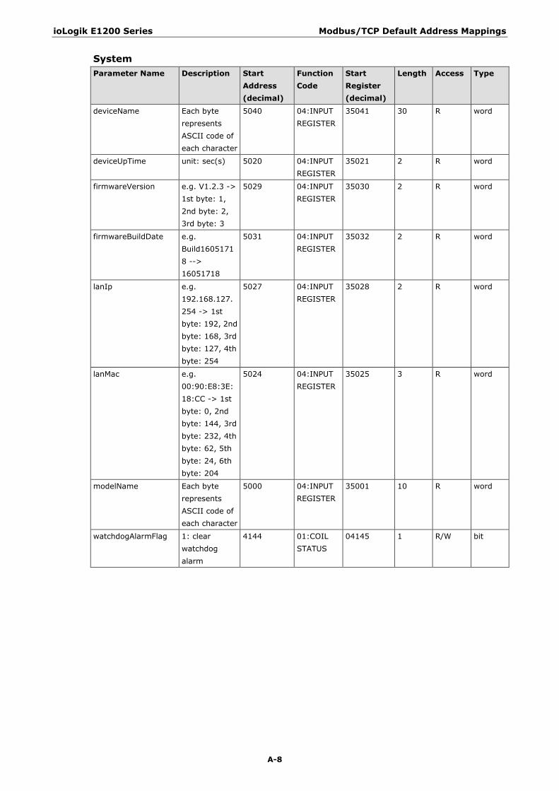
ioLogik E1200 Series Modbus/TCP Default Address Mappings
A-8
System Parameter Name Description Start
Address (decimal)
Function Code
Start Register (decimal)
Length Access Type
deviceName Each byte represents ASCII code of each character
5040 04:INPUT REGISTER
35041 30 R word
deviceUpTime unit: sec(s) 5020 04:INPUT REGISTER
35021 2 R word
firmwareVersion e.g. V1.2.3 -> 1st byte: 1, 2nd byte: 2, 3rd byte: 3
5029 04:INPUT REGISTER
35030 2 R word
firmwareBuildDate e.g. Build16051718 --> 16051718
5031 04:INPUT REGISTER
35032 2 R word
lanIp e.g. 192.168.127.254 -> 1st byte: 192, 2nd byte: 168, 3rd byte: 127, 4th byte: 254
5027 04:INPUT REGISTER
35028 2 R word
lanMac e.g. 00:90:E8:3E:18:CC -> 1st byte: 0, 2nd byte: 144, 3rd byte: 232, 4th byte: 62, 5th byte: 24, 6th byte: 204
5024 04:INPUT REGISTER
35025 3 R word
modelName Each byte represents ASCII code of each character
5000 04:INPUT REGISTER
35001 10 R word
watchdogAlarmFlag 1: clear watchdog alarm
4144 01:COIL STATUS
04145 1 R/W bit
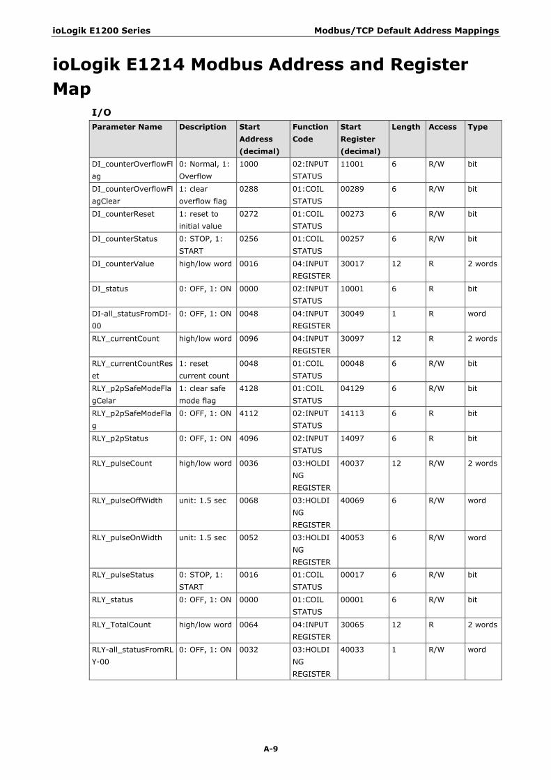
ioLogik E1200 Series Modbus/TCP Default Address Mappings
A-9
ioLogik E1214 Modbus Address and Register Map
I/O Parameter Name Description Start
Address (decimal)
Function Code
Start Register (decimal)
Length Access Type
DI_counterOverflowFlag
0: Normal, 1: Overflow
1000 02:INPUT STATUS
11001 6 R/W bit
DI_counterOverflowFlagClear
1: clear overflow flag
0288 01:COIL STATUS
00289 6 R/W bit
DI_counterReset 1: reset to initial value
0272 01:COIL STATUS
00273 6 R/W bit
DI_counterStatus 0: STOP, 1: START
0256 01:COIL STATUS
00257 6 R/W bit
DI_counterValue high/low word 0016 04:INPUT REGISTER
30017 12 R 2 words
DI_status 0: OFF, 1: ON 0000 02:INPUT STATUS
10001 6 R bit
DI-all_statusFromDI-00
0: OFF, 1: ON 0048 04:INPUT REGISTER
30049 1 R word
RLY_currentCount high/low word 0096 04:INPUT REGISTER
30097 12 R 2 words
RLY_currentCountReset
1: reset current count
0048 01:COIL STATUS
00048 6 R/W bit
RLY_p2pSafeModeFlagCelar
1: clear safe mode flag
4128 01:COIL STATUS
04129 6 R/W bit
RLY_p2pSafeModeFlag
0: OFF, 1: ON 4112 02:INPUT STATUS
14113 6 R bit
RLY_p2pStatus 0: OFF, 1: ON 4096 02:INPUT STATUS
14097 6 R bit
RLY_pulseCount high/low word 0036 03:HOLDING REGISTER
40037 12 R/W 2 words
RLY_pulseOffWidth unit: 1.5 sec 0068 03:HOLDING REGISTER
40069 6 R/W word
RLY_pulseOnWidth unit: 1.5 sec 0052 03:HOLDING REGISTER
40053 6 R/W word
RLY_pulseStatus 0: STOP, 1: START
0016 01:COIL STATUS
00017 6 R/W bit
RLY_status 0: OFF, 1: ON 0000 01:COIL STATUS
00001 6 R/W bit
RLY_TotalCount high/low word 0064 04:INPUT REGISTER
30065 12 R 2 words
RLY-all_statusFromRLY-00
0: OFF, 1: ON 0032 03:HOLDING REGISTER
40033 1 R/W word

ioLogik E1200 Series Modbus/TCP Default Address Mappings
A-10
System Parameter Name Description Start
Address (decimal)
Function Code
Start Register (decimal)
Length Access Type
deviceName Each byte represents ASCII code of each character
5040 04:INPUT REGISTER
35041 30 R word
deviceUpTime unit: sec(s) 5020 04:INPUT REGISTER
35021 2 R word
firmwareVersion e.g. V1.2.3 -> 1st byte: 1, 2nd byte: 2, 3rd byte: 3
5029 04:INPUT REGISTER
35030 2 R word
firmwareBuildDate e.g. Build16051718 --> 16051718
5031 04:INPUT REGISTER
35032 2 R word
lanIp e.g. 192.168.127.254 -> 1st byte: 192, 2nd byte: 168, 3rd byte: 127, 4th byte: 254
5027 04:INPUT REGISTER
35028 2 R word
lanMac e.g. 00:90:E8:3E:18:CC -> 1st byte: 0, 2nd byte: 144, 3rd byte: 232, 4th byte: 62, 5th byte: 24, 6th byte: 204
5024 04:INPUT REGISTER
35025 3 R word
modelName Each byte represents ASCII code of each character
5000 04:INPUT REGISTER
35001 10 R word
watchdogAlarmFlag 1: clear watchdog alarm
4144 01:COIL STATUS
04145 1 R/W bit
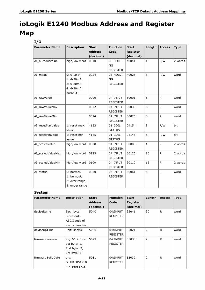
ioLogik E1200 Series Modbus/TCP Default Address Mappings
A-11
ioLogik E1240 Modbus Address and Register Map
I/O Parameter Name Description Start
Address (decimal)
Function Code
Start Register (decimal)
Length Access Type
AI_burnoutValue high/low word 0040 03:HOLDING REGISTER
40041 16 R/W 2 words
AI_mode 0: 0-10 V 1: 4-20mA 2: 0-20mA 4: 4-20mA burnout
0024 03:HOLDING REGISTER
40025 8 R/W word
AI_rawValue 0000 04:INPUT REGISTER
30001 8 R word
AI_rawValueMax 0032 04:INPUT REGISTER
30033 8 R word
AI_rawValueMin 0024 04:INPUT REGISTER
30025 8 R word
AI_resetMaxValue 1: reset max. value
4153 01:COIL STATUS
04154 8 R/W bit
AI_resetMinValue 1: reset min. value
4145 01:COIL STATUS
04146 8 R/W bit
AI_scaledValue high/low word 0008 04:INPUT REGISTER
30009 16 R 2 words
AI_scaledValueMax high/low word 0125 04:INPUT REGISTER
30126 16 R 2 words
AI_scaledValueMin high/low word 0109 04:INPUT REGISTER
30110 16 R 2 words
AI_status 0: normal, 1: burnout, 2: over range, 3: under range
0060 04:INPUT REGISTER
30061 8 R word
System Parameter Name Description Start
Address (decimal)
Function Code
Start Register (decimal)
Length Access Type
deviceName Each byte represents ASCII code of each character
5040 04:INPUT REGISTER
35041 30 R word
deviceUpTime unit: sec(s) 5020 04:INPUT REGISTER
35021 2 R word
firmwareVersion e.g. V1.2.3 -> 1st byte: 1, 2nd byte: 2, 3rd byte: 3
5029 04:INPUT REGISTER
35030 2 R word
firmwareBuildDate e.g. Build16051718 --> 16051718
5031 04:INPUT REGISTER
35032 2 R word
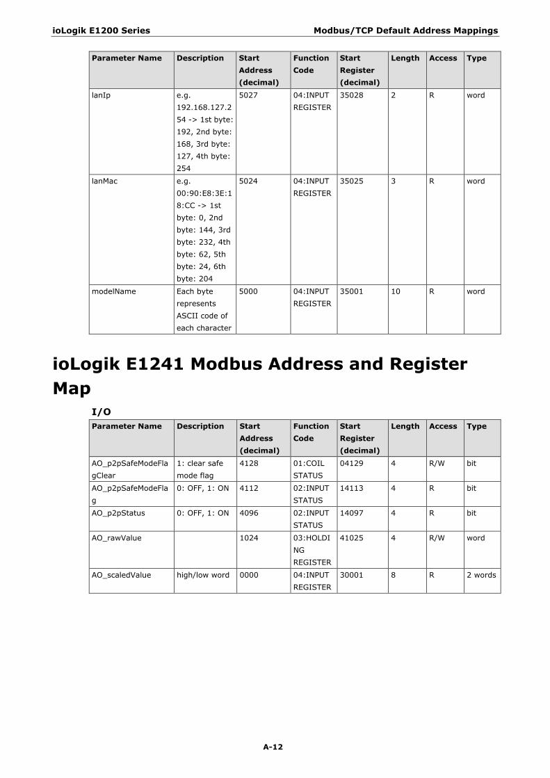
ioLogik E1200 Series Modbus/TCP Default Address Mappings
A-12
Parameter Name Description Start Address (decimal)
Function Code
Start Register (decimal)
Length Access Type
lanIp e.g. 192.168.127.254 -> 1st byte: 192, 2nd byte: 168, 3rd byte: 127, 4th byte: 254
5027 04:INPUT REGISTER
35028 2 R word
lanMac e.g. 00:90:E8:3E:18:CC -> 1st byte: 0, 2nd byte: 144, 3rd byte: 232, 4th byte: 62, 5th byte: 24, 6th byte: 204
5024 04:INPUT REGISTER
35025 3 R word
modelName Each byte represents ASCII code of each character
5000 04:INPUT REGISTER
35001 10 R word
ioLogik E1241 Modbus Address and Register Map
I/O Parameter Name Description Start
Address (decimal)
Function Code
Start Register (decimal)
Length Access Type
AO_p2pSafeModeFlagClear
1: clear safe mode flag
4128 01:COIL STATUS
04129 4 R/W bit
AO_p2pSafeModeFlag
0: OFF, 1: ON 4112 02:INPUT STATUS
14113 4 R bit
AO_p2pStatus 0: OFF, 1: ON 4096 02:INPUT STATUS
14097 4 R bit
AO_rawValue 1024 03:HOLDING REGISTER
41025 4 R/W word
AO_scaledValue high/low word 0000 04:INPUT REGISTER
30001 8 R 2 words
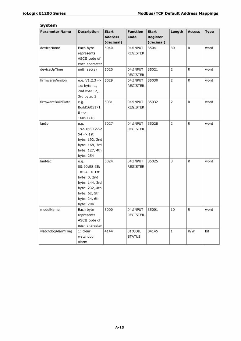
ioLogik E1200 Series Modbus/TCP Default Address Mappings
A-13
System Parameter Name Description Start
Address (decimal)
Function Code
Start Register (decimal)
Length Access Type
deviceName Each byte represents ASCII code of each character
5040 04:INPUT REGISTER
35041 30 R word
deviceUpTime unit: sec(s) 5020 04:INPUT REGISTER
35021 2 R word
firmwareVersion e.g. V1.2.3 -> 1st byte: 1, 2nd byte: 2, 3rd byte: 3
5029 04:INPUT REGISTER
35030 2 R word
firmwareBuildDate e.g. Build16051718 --> 16051718
5031 04:INPUT REGISTER
35032 2 R word
lanIp e.g. 192.168.127.254 -> 1st byte: 192, 2nd byte: 168, 3rd byte: 127, 4th byte: 254
5027 04:INPUT REGISTER
35028 2 R word
lanMac e.g. 00:90:E8:3E:18:CC -> 1st byte: 0, 2nd byte: 144, 3rd byte: 232, 4th byte: 62, 5th byte: 24, 6th byte: 204
5024 04:INPUT REGISTER
35025 3 R word
modelName Each byte represents ASCII code of each character
5000 04:INPUT REGISTER
35001 10 R word
watchdogAlarmFlag 1: clear watchdog alarm
4144 01:COIL STATUS
04145 1 R/W bit
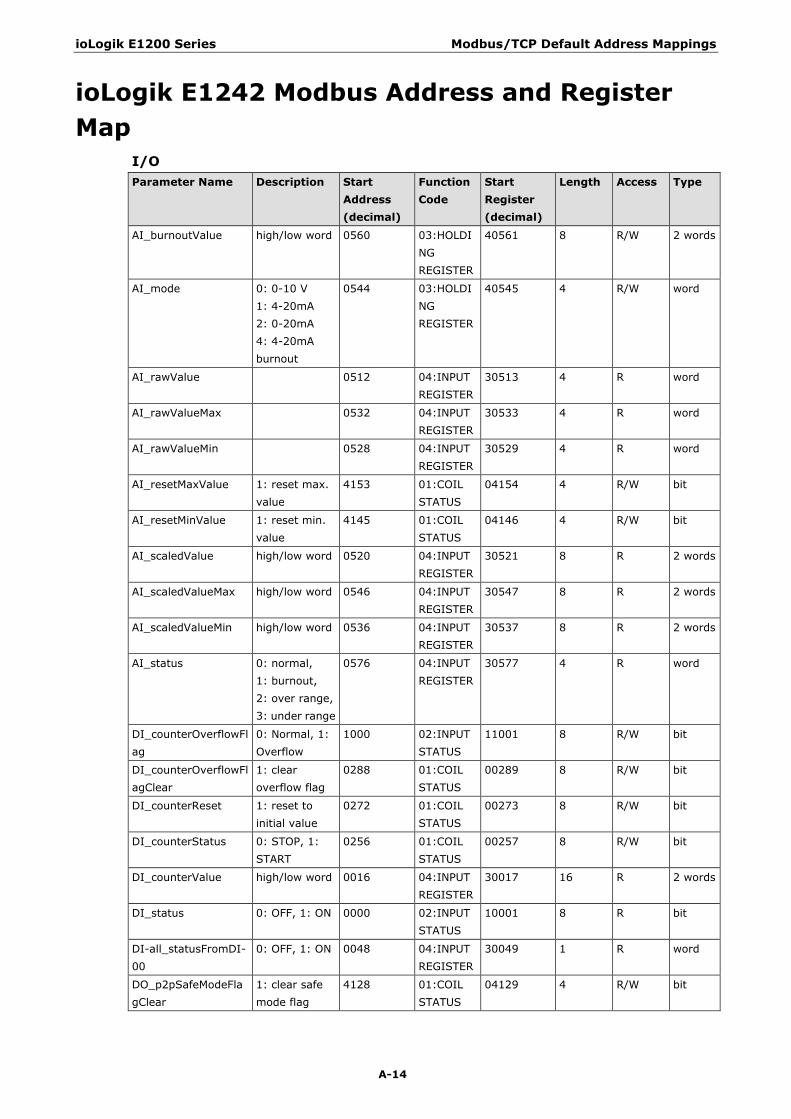
ioLogik E1200 Series Modbus/TCP Default Address Mappings
A-14
ioLogik E1242 Modbus Address and Register Map
I/O Parameter Name Description Start
Address (decimal)
Function Code
Start Register (decimal)
Length Access Type
AI_burnoutValue high/low word 0560 03:HOLDING REGISTER
40561 8 R/W 2 words
AI_mode 0: 0-10 V 1: 4-20mA 2: 0-20mA 4: 4-20mA burnout
0544 03:HOLDING REGISTER
40545 4 R/W word
AI_rawValue 0512 04:INPUT REGISTER
30513 4 R word
AI_rawValueMax 0532 04:INPUT REGISTER
30533 4 R word
AI_rawValueMin 0528 04:INPUT REGISTER
30529 4 R word
AI_resetMaxValue 1: reset max. value
4153 01:COIL STATUS
04154 4 R/W bit
AI_resetMinValue 1: reset min. value
4145 01:COIL STATUS
04146 4 R/W bit
AI_scaledValue high/low word 0520 04:INPUT REGISTER
30521 8 R 2 words
AI_scaledValueMax high/low word 0546 04:INPUT REGISTER
30547 8 R 2 words
AI_scaledValueMin high/low word 0536 04:INPUT REGISTER
30537 8 R 2 words
AI_status 0: normal, 1: burnout, 2: over range, 3: under range
0576 04:INPUT REGISTER
30577 4 R word
DI_counterOverflowFlag
0: Normal, 1: Overflow
1000 02:INPUT STATUS
11001 8 R/W bit
DI_counterOverflowFlagClear
1: clear overflow flag
0288 01:COIL STATUS
00289 8 R/W bit
DI_counterReset 1: reset to initial value
0272 01:COIL STATUS
00273 8 R/W bit
DI_counterStatus 0: STOP, 1: START
0256 01:COIL STATUS
00257 8 R/W bit
DI_counterValue high/low word 0016 04:INPUT REGISTER
30017 16 R 2 words
DI_status 0: OFF, 1: ON 0000 02:INPUT STATUS
10001 8 R bit
DI-all_statusFromDI-00
0: OFF, 1: ON 0048 04:INPUT REGISTER
30049 1 R word
DO_p2pSafeModeFlagClear
1: clear safe mode flag
4128 01:COIL STATUS
04129 4 R/W bit

ioLogik E1200 Series Modbus/TCP Default Address Mappings
A-15
Parameter Name Description Start Address (decimal)
Function Code
Start Register (decimal)
Length Access Type
DO_p2pSafeModeFlag
0: OFF, 1: ON 4112 02:INPUT STATUS
14113 4 R bit
DO_p2pStatus 0: OFF, 1: ON 4096 02:INPUT STATUS
14097 4 R bit
DO_pulseCount 0036 03:HOLDING REGISTER
40037 4 R/W word
DO_pulseOffWidth unit: 1 ms 0068 03:HOLDING REGISTER
40069 4 R/W word
DO_pulseOnWidth unit: 1 ms 0052 03:HOLDING REGISTER
40053 4 R/W word
DO_pulseStatus 0: STOP, 1: START
0016 01:COIL STATUS
00017 4 R/W bit
DO_status 0: OFF, 1: ON 0000 01:COIL STATUS
00001 4 R/W bit
DO-all_statusFromDO-00
0: OFF, 1: ON 0032 03:HOLDING REGISTER
40033 1 R/W word
System Parameter Name Description Start
Address (decimal)
Function Code
Start Register (decimal)
Length Access Type
deviceName Each byte represents ASCII code of each character
5040 04:INPUT REGISTER
35041 30 R word
deviceUpTime unit: sec(s) 5020 04:INPUT REGISTER
35021 2 R word
firmwareVersion e.g. V1.2.3 -> 1st byte: 1, 2nd byte: 2, 3rd byte: 3
5029 04:INPUT REGISTER
35030 2 R word
firmwareBuildDate e.g. Build16051718 --> 16051718
5031 04:INPUT REGISTER
35032 2 R word
lanIp e.g. 192.168.127.254 -> 1st byte: 192, 2nd byte: 168, 3rd byte: 127, 4th byte: 254
5027 04:INPUT REGISTER
35028 2 R word
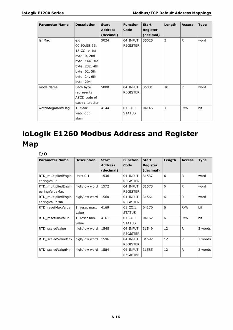
ioLogik E1200 Series Modbus/TCP Default Address Mappings
A-16
Parameter Name Description Start Address (decimal)
Function Code
Start Register (decimal)
Length Access Type
lanMac e.g. 00:90:E8:3E:18:CC -> 1st byte: 0, 2nd byte: 144, 3rd byte: 232, 4th byte: 62, 5th byte: 24, 6th byte: 204
5024 04:INPUT REGISTER
35025 3 R word
modelName Each byte represents ASCII code of each character
5000 04:INPUT REGISTER
35001 10 R word
watchdogAlarmFlag 1: clear watchdog alarm
4144 01:COIL STATUS
04145 1 R/W bit
ioLogik E1260 Modbus Address and Register Map
I/O Parameter Name Description Start
Address (decimal)
Function Code
Start Register (decimal)
Length Access Type
RTD_multipliedEngineeringValue
Unit: 0.1 1536 04:INPUT REGISTER
31537 6 R word
RTD_multipliedEngineeringValueMax
high/low word 1572 04:INPUT REGISTER
31573 6 R word
RTD_multipliedEngineeringValueMin
high/low word 1560 04:INPUT REGISTER
31561 6 R word
RTD_resetMaxValue 1: reset max. value
4169 01:COIL STATUS
04170 6 R/W bit
RTD_resetMinValue 1: reset min. value
4161 01:COIL STATUS
04162 6 R/W bit
RTD_scaledValue high/low word 1548 04:INPUT REGISTER
31549 12 R 2 words
RTD_scaledValueMax high/low word 1596 04:INPUT REGISTER
31597 12 R 2 words
RTD_scaledValueMin high/low word 1584 04:INPUT REGISTER
31585 12 R 2 words

ioLogik E1200 Series Modbus/TCP Default Address Mappings
A-17
System Parameter Name Description Start
Address (decimal)
Function Code
Start Register (decimal)
Length Access Type
deviceName Each byte represents ASCII code of each character
5040 04:INPUT REGISTER
35041 30 R word
deviceUpTime unit: sec(s) 5020 04:INPUT REGISTER
35021 2 R word
firmwareVersion e.g. V1.2.3 -> 1st byte: 1, 2nd byte: 2, 3rd byte: 3
5029 04:INPUT REGISTER
35030 2 R word
firmwareBuildDate e.g. Build16051718 --> 16051718
5031 04:INPUT REGISTER
35032 2 R word
lanIp e.g. 192.168.127.254 -> 1st byte: 192, 2nd byte: 168, 3rd byte: 127, 4th byte: 254
5027 04:INPUT REGISTER
35028 2 R word
lanMac e.g. 00:90:E8:3E:18:CC -> 1st byte: 0, 2nd byte: 144, 3rd byte: 232, 4th byte: 62, 5th byte: 24, 6th byte: 204
5024 04:INPUT REGISTER
35025 3 R word
modelName Each byte represents ASCII code of each character
5000 04:INPUT REGISTER
35001 10 R word
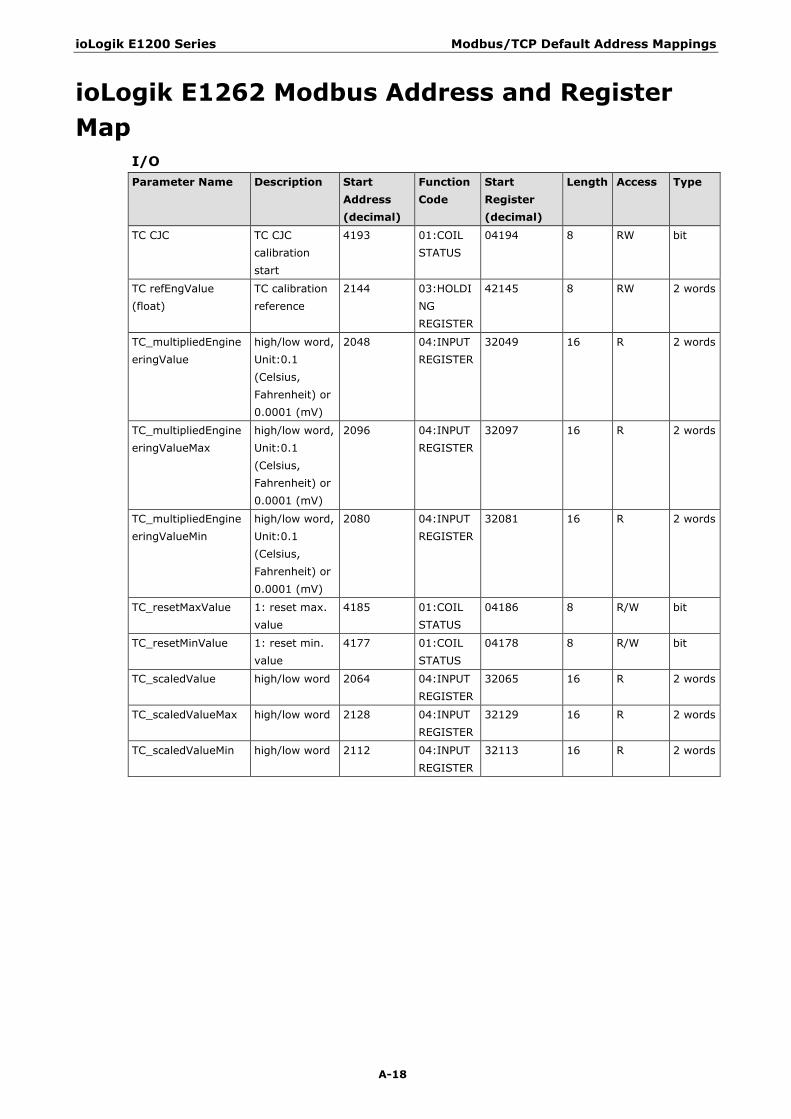
ioLogik E1200 Series Modbus/TCP Default Address Mappings
A-18
ioLogik E1262 Modbus Address and Register Map
I/O Parameter Name Description Start
Address (decimal)
Function Code
Start Register (decimal)
Length Access Type
TC CJC TC CJC calibration start
4193 01:COIL STATUS
04194 8 RW bit
TC refEngValue (float)
TC calibration reference
2144 03:HOLDING REGISTER
42145 8 RW 2 words
TC_multipliedEngineeringValue
high/low word, Unit:0.1 (Celsius, Fahrenheit) or 0.0001 (mV)
2048 04:INPUT REGISTER
32049 16 R 2 words
TC_multipliedEngineeringValueMax
high/low word, Unit:0.1 (Celsius, Fahrenheit) or 0.0001 (mV)
2096 04:INPUT REGISTER
32097 16 R 2 words
TC_multipliedEngineeringValueMin
high/low word, Unit:0.1 (Celsius, Fahrenheit) or 0.0001 (mV)
2080 04:INPUT REGISTER
32081 16 R 2 words
TC_resetMaxValue 1: reset max. value
4185 01:COIL STATUS
04186 8 R/W bit
TC_resetMinValue 1: reset min. value
4177 01:COIL STATUS
04178 8 R/W bit
TC_scaledValue high/low word 2064 04:INPUT REGISTER
32065 16 R 2 words
TC_scaledValueMax high/low word 2128 04:INPUT REGISTER
32129 16 R 2 words
TC_scaledValueMin high/low word 2112 04:INPUT REGISTER
32113 16 R 2 words
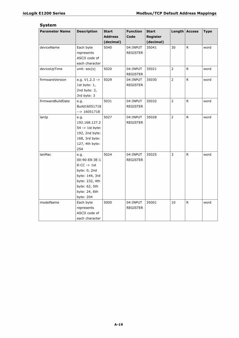
ioLogik E1200 Series Modbus/TCP Default Address Mappings
A-19
System Parameter Name Description Start
Address (decimal)
Function Code
Start Register (decimal)
Length Access Type
deviceName Each byte represents ASCII code of each character
5040 04:INPUT REGISTER
35041 30 R word
deviceUpTime unit: sec(s) 5020 04:INPUT REGISTER
35021 2 R word
firmwareVersion e.g. V1.2.3 -> 1st byte: 1, 2nd byte: 2, 3rd byte: 3
5029 04:INPUT REGISTER
35030 2 R word
firmwareBuildDate e.g. Build16051718 --> 16051718
5031 04:INPUT REGISTER
35032 2 R word
lanIp e.g. 192.168.127.254 -> 1st byte: 192, 2nd byte: 168, 3rd byte: 127, 4th byte: 254
5027 04:INPUT REGISTER
35028 2 R word
lanMac e.g. 00:90:E8:3E:18:CC -> 1st byte: 0, 2nd byte: 144, 3rd byte: 232, 4th byte: 62, 5th byte: 24, 6th byte: 204
5024 04:INPUT REGISTER
35025 3 R word
modelName Each byte represents ASCII code of each character
5000 04:INPUT REGISTER
35001 10 R word

B B. EtherNet/IP Default Address Mappings
ioLogik E1200 EtherNet/IP Map Supported Service Service Code Class Level Instance Level Service Name Description
0x05 No Yes Reset Restart device
0x0E Yes Yes Get_Attribute_Single Read an attribute
0x10 No Yes Set_Attribute_Single Modify an attribute
Assembly Object (0x04) Instance Attribute ID Access Name Data Type Description
0x00 0x01 GET Revision UINT Revision of this object
0x65 0x03 GET Input Data ARRAY of BYTE Data Map by Models
0x65 0x04 GET Size UINT Number of BYTE in attribute 0x03
0x66 0x03 SET Output Data ARRAY of BYTE Data Map by Models
0x66 0x04 GET Size UINT Number of BYTE in attribute 0x03
Input Data Map by Models Model Channels BYTE # Access Name Data
Type Description
ioLogik E1210
DI-15…00 1…0 GET diStatus BOOL DI - DI mode - status (0: OFF, 1: ON)
65…2 GET diCounterValue
UDINT DI - Counter mode - value
ioLogik E1211
DO-15…00 1…0 GET doStatus BOOL DO - DO mode - status (0: OFF, 1: ON)
ioLogik E1212
DI-15…00 1…0 GET diStatus BOOL DI - DI mode - status (0: OFF, 1: ON)
65…2 GET diCounterValue
UDINT DI - Counter mode - value
DO-07…00 66 GET doStatus BOOL DO - DO mode - status (0: OFF, 1: ON)
ioLogik E1213
DI-11…00 1…0 GET diStatus BOOL DI - DI mode - status (0: OFF, 1: ON)
49…2 GET diCounterValue
UDINT DI - Counter mode - value
DO-07…00 50 GET doStatus BOOL DO - DO mode - status (0: OFF, 1: ON)
ioLogik E1214
DI-05…00 0 GET diStatus BOOL DI - DI mode - status (0: OFF, 1: ON)
24…1 GET diCounterValue
UDINT DI - Counter mode - value
RLY-05…00 25 GET relayStatus BOOL Relay - Relay mode - status (0: OFF, 1: ON)
ioLogik E1240
AI-07…00 15…0 GET aiValueRaw UINT AI - raw value
ioLogik E1241
AO-03…00 7…0 GET aoValueRaw UINT AO - raw value
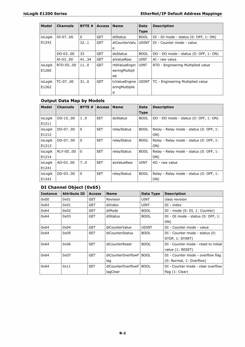
ioLogik E1200 Series EtherNet/IP Default Address Mappings
B-2
Model Channels BYTE # Access Name Data Type
Description
ioLogik E1242
DI-07…00 0 GET diStatus BOOL DI - DI mode - status (0: OFF, 1: ON)
32…1 GET diCounterValue
UDINT DI - Counter mode - value
DO-03…00 33 GET doStatus BOOL DO - DO mode - status (0: OFF, 1: ON)
AI-03…00 41…34 GET aiValueRaw UINT AI - raw value
ioLogik E1260
RTD-05…00 11…0 GET rtdValueEngineeringMultiplied
UINT RTD - Engineering Multiplied value
ioLogik E1262
TC-07…00 31…0 GET tcValueEngineeringMultiplied
UDINT TC - Engineering Multiplied value
Output Data Map by Models Model Channels BYTE # Access Name Data
Type Description
ioLogik E1211
DO-15…00 1…0 SET doStatus BOOL DO - DO mode - status (0: OFF, 1: ON)
ioLogik E1212
DO-07…00 0 SET relayStatus BOOL Relay - Relay mode - status (0: OFF, 1: ON)
ioLogik E1213
DO-07…00 0 SET relayStatus BOOL Relay - Relay mode - status (0: OFF, 1: ON)
ioLogik E1214
RLY-05…00 0 SET relayStatus BOOL Relay - Relay mode - status (0: OFF, 1: ON)
ioLogik E1241
AO-03…00 7…0 SET aoValueRaw UINT AO - raw value
ioLogik E1242
DO-03…00 0 SET relayStatus BOOL Relay - Relay mode - status (0: OFF, 1: ON)
DI Channel Object (0x65) Instance Attribute ID Access Name Data Type Description
0x00 0x01 GET Revision UINT class revision
0x64 0x01 GET diIndex UINT DI - index
0x64 0x02 GET diMode BOOL DI - mode (0: DI, 1: Counter)
0x64 0x03 GET diStatus BOOL DI - DI mode - status (0: OFF, 1: ON)
0x64 0x04 GET diCounterValue UDINT DI - Counter mode - value
0x64 0x05 SET diCounterStatus BOOL DI - Counter mode - status (0: STOP, 1: START)
0x64 0x06 SET diCounterReset BOOL DI - Counter mode - reset to initial value (1: RESET)
0x64 0x07 GET diCounterOverflowFlag
BOOL DI - Counter mode - overflow flag (0: Normal, 1: Overflow)
0x64 0x11 SET diCounterOverflowFlagClear
BOOL DI - Counter mode - clear overflow flag (1: Clear)
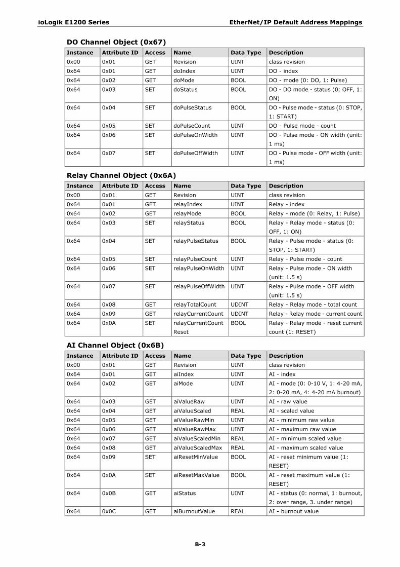
ioLogik E1200 Series EtherNet/IP Default Address Mappings
B-3
DO Channel Object (0x67) Instance Attribute ID Access Name Data Type Description 0x00 0x01 GET Revision UINT class revision
0x64 0x01 GET doIndex UINT DO - index
0x64 0x02 GET doMode BOOL DO - mode (0: DO, 1: Pulse)
0x64 0x03 SET doStatus BOOL DO - DO mode - status (0: OFF, 1: ON)
0x64 0x04 SET doPulseStatus BOOL DO - Pulse mode - status (0: STOP, 1: START)
0x64 0x05 SET doPulseCount UINT DO - Pulse mode - count
0x64 0x06 SET doPulseOnWidth UINT DO - Pulse mode - ON width (unit: 1 ms)
0x64 0x07 SET doPulseOffWidth UINT DO - Pulse mode - OFF width (unit: 1 ms)
Relay Channel Object (0x6A) Instance Attribute ID Access Name Data Type Description
0x00 0x01 GET Revision UINT class revision
0x64 0x01 GET relayIndex UINT Relay - index
0x64 0x02 GET relayMode BOOL Relay - mode (0: Relay, 1: Pulse)
0x64 0x03 SET relayStatus BOOL Relay - Relay mode - status (0: OFF, 1: ON)
0x64 0x04 SET relayPulseStatus BOOL Relay - Pulse mode - status (0: STOP, 1: START)
0x64 0x05 SET relayPulseCount UINT Relay - Pulse mode - count
0x64 0x06 SET relayPulseOnWidth UINT Relay - Pulse mode - ON width (unit: 1.5 s)
0x64 0x07 SET relayPulseOffWidth UINT Relay - Pulse mode - OFF width (unit: 1.5 s)
0x64 0x08 GET relayTotalCount UDINT Relay - Relay mode - total count
0x64 0x09 GET relayCurrentCount UDINT Relay - Relay mode - current count
0x64 0x0A SET relayCurrentCountReset
BOOL Relay - Relay mode - reset current count (1: RESET)
AI Channel Object (0x6B) Instance Attribute ID Access Name Data Type Description 0x00 0x01 GET Revision UINT class revision
0x64 0x01 GET aiIndex UINT AI - index
0x64 0x02 GET aiMode UINT AI - mode (0: 0-10 V, 1: 4-20 mA, 2: 0-20 mA, 4: 4-20 mA burnout)
0x64 0x03 GET aiValueRaw UINT AI - raw value
0x64 0x04 GET aiValueScaled REAL AI - scaled value
0x64 0x05 GET aiValueRawMin UINT AI - minimum raw value
0x64 0x06 GET aiValueRawMax UINT AI - maximum raw value
0x64 0x07 GET aiValueScaledMin REAL AI - minimum scaled value
0x64 0x08 GET aiValueScaledMax REAL AI - maximum scaled value
0x64 0x09 SET aiResetMinValue BOOL AI - reset minimum value (1: RESET)
0x64 0x0A SET aiResetMaxValue BOOL AI - reset maximum value (1: RESET)
0x64 0x0B GET aiStatus UINT AI - status (0: normal, 1: burnout, 2: over range, 3. under range)
0x64 0x0C GET aiBurnoutValue REAL AI - burnout value
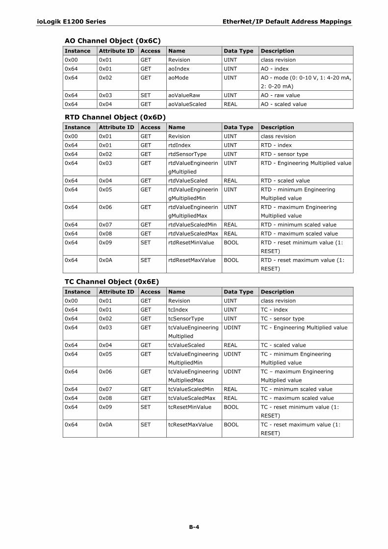
ioLogik E1200 Series EtherNet/IP Default Address Mappings
B-4
AO Channel Object (0x6C) Instance Attribute ID Access Name Data Type Description 0x00 0x01 GET Revision UINT class revision
0x64 0x01 GET aoIndex UINT AO - index
0x64 0x02 GET aoMode UINT AO - mode (0: 0-10 V, 1: 4-20 mA, 2: 0-20 mA)
0x64 0x03 SET aoValueRaw UINT AO - raw value
0x64 0x04 GET aoValueScaled REAL AO - scaled value
RTD Channel Object (0x6D) Instance Attribute ID Access Name Data Type Description
0x00 0x01 GET Revision UINT class revision
0x64 0x01 GET rtdIndex UINT RTD - index
0x64 0x02 GET rtdSensorType UINT RTD - sensor type
0x64 0x03 GET rtdValueEngineeringMultiplied
UINT RTD - Engineering Multiplied value
0x64 0x04 GET rtdValueScaled REAL RTD - scaled value
0x64 0x05 GET rtdValueEngineeringMultipliedMin
UINT RTD - minimum Engineering Multiplied value
0x64 0x06 GET rtdValueEngineeringMultipliedMax
UINT RTD - maximum Engineering Multiplied value
0x64 0x07 GET rtdValueScaledMin REAL RTD - minimum scaled value
0x64 0x08 GET rtdValueScaledMax REAL RTD - maximum scaled value
0x64 0x09 SET rtdResetMinValue BOOL RTD - reset minimum value (1: RESET)
0x64 0x0A SET rtdResetMaxValue BOOL RTD - reset maximum value (1: RESET)
TC Channel Object (0x6E) Instance Attribute ID Access Name Data Type Description 0x00 0x01 GET Revision UINT class revision
0x64 0x01 GET tcIndex UINT TC - index
0x64 0x02 GET tcSensorType UINT TC - sensor type
0x64 0x03 GET tcValueEngineeringMultiplied
UDINT TC - Engineering Multiplied value
0x64 0x04 GET tcValueScaled REAL TC - scaled value
0x64 0x05 GET tcValueEngineeringMultipliedMin
UDINT TC - minimum Engineering Multiplied value
0x64 0x06 GET tcValueEngineeringMultipliedMax
UDINT TC – maximum Engineering Multiplied value
0x64 0x07 GET tcValueScaledMin REAL TC - minimum scaled value
0x64 0x08 GET tcValueScaledMax REAL TC - maximum scaled value
0x64 0x09 SET tcResetMinValue BOOL TC - reset minimum value (1: RESET)
0x64 0x0A SET tcResetMaxValue BOOL TC - reset maximum value (1: RESET)
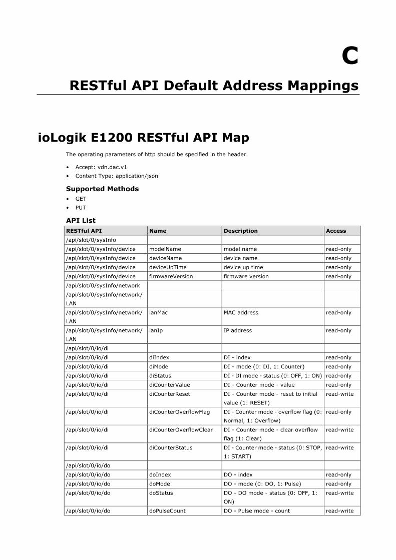
C C. RESTful API Default Address Mappings
ioLogik E1200 RESTful API Map The operating parameters of http should be specified in the header.
• Accept: vdn.dac.v1 • Content Type: application/json
Supported Methods • GET • PUT
API List RESTful API Name Description Access /api/slot/0/sysInfo
/api/slot/0/sysInfo/device modelName model name read-only
/api/slot/0/sysInfo/device deviceName device name read-only
/api/slot/0/sysInfo/device deviceUpTime device up time read-only
/api/slot/0/sysInfo/device firmwareVersion firmware version read-only
/api/slot/0/sysInfo/network
/api/slot/0/sysInfo/network/LAN
/api/slot/0/sysInfo/network/LAN
lanMac MAC address read-only
/api/slot/0/sysInfo/network/LAN
lanIp IP address read-only
/api/slot/0/io/di
/api/slot/0/io/di diIndex DI - index read-only
/api/slot/0/io/di diMode DI - mode (0: DI, 1: Counter) read-only
/api/slot/0/io/di diStatus DI - DI mode - status (0: OFF, 1: ON) read-only
/api/slot/0/io/di diCounterValue DI - Counter mode - value read-only
/api/slot/0/io/di diCounterReset DI - Counter mode - reset to initial value (1: RESET)
read-write
/api/slot/0/io/di diCounterOverflowFlag DI - Counter mode - overflow flag (0: Normal, 1: Overflow)
read-only
/api/slot/0/io/di diCounterOverflowClear DI - Counter mode - clear overflow flag (1: Clear)
read-write
/api/slot/0/io/di diCounterStatus DI - Counter mode - status (0: STOP, 1: START)
read-write
/api/slot/0/io/do
/api/slot/0/io/do doIndex DO - index read-only
/api/slot/0/io/do doMode DO - mode (0: DO, 1: Pulse) read-only
/api/slot/0/io/do doStatus DO - DO mode - status (0: OFF, 1: ON)
read-write
/api/slot/0/io/do doPulseCount DO - Pulse mode - count read-write
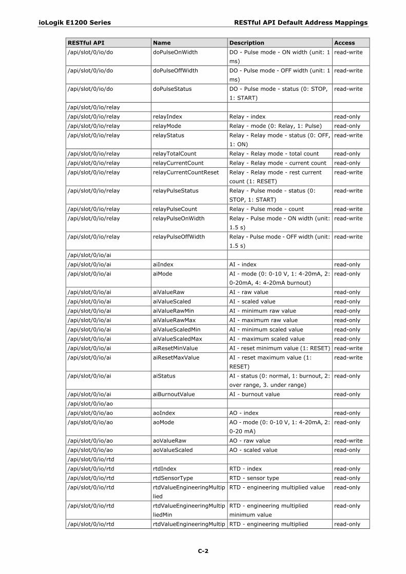
ioLogik E1200 Series RESTful API Default Address Mappings
C-2
RESTful API Name Description Access
/api/slot/0/io/do doPulseOnWidth DO - Pulse mode - ON width (unit: 1 ms)
read-write
/api/slot/0/io/do doPulseOffWidth DO - Pulse mode - OFF width (unit: 1 ms)
read-write
/api/slot/0/io/do doPulseStatus DO - Pulse mode - status (0: STOP, 1: START)
read-write
/api/slot/0/io/relay
/api/slot/0/io/relay relayIndex Relay - index read-only
/api/slot/0/io/relay relayMode Relay - mode (0: Relay, 1: Pulse) read-only
/api/slot/0/io/relay relayStatus Relay - Relay mode - status (0: OFF, 1: ON)
read-write
/api/slot/0/io/relay relayTotalCount Relay - Relay mode - total count read-only
/api/slot/0/io/relay relayCurrentCount Relay - Relay mode - current count read-only
/api/slot/0/io/relay relayCurrentCountReset Relay - Relay mode - rest current count (1: RESET)
read-write
/api/slot/0/io/relay relayPulseStatus Relay - Pulse mode - status (0: STOP, 1: START)
read-write
/api/slot/0/io/relay relayPulseCount Relay - Pulse mode - count read-write
/api/slot/0/io/relay relayPulseOnWidth Relay - Pulse mode - ON width (unit: 1.5 s)
read-write
/api/slot/0/io/relay relayPulseOffWidth Relay - Pulse mode - OFF width (unit: 1.5 s)
read-write
/api/slot/0/io/ai
/api/slot/0/io/ai aiIndex AI - index read-only
/api/slot/0/io/ai aiMode AI - mode (0: 0-10 V, 1: 4-20mA, 2: 0-20mA, 4: 4-20mA burnout)
read-only
/api/slot/0/io/ai aiValueRaw AI - raw value read-only
/api/slot/0/io/ai aiValueScaled AI - scaled value read-only
/api/slot/0/io/ai aiValueRawMin AI - minimum raw value read-only
/api/slot/0/io/ai aiValueRawMax AI - maximum raw value read-only
/api/slot/0/io/ai aiValueScaledMin AI - minimum scaled value read-only
/api/slot/0/io/ai aiValueScaledMax AI - maximum scaled value read-only
/api/slot/0/io/ai aiResetMinValue AI - reset minimum value (1: RESET) read-write
/api/slot/0/io/ai aiResetMaxValue AI - reset maximum value (1: RESET)
read-write
/api/slot/0/io/ai aiStatus AI - status (0: normal, 1: burnout, 2: over range, 3. under range)
read-only
/api/slot/0/io/ai aiBurnoutValue AI - burnout value read-only
/api/slot/0/io/ao
/api/slot/0/io/ao aoIndex AO - index read-only
/api/slot/0/io/ao aoMode AO - mode (0: 0-10 V, 1: 4-20mA, 2: 0-20 mA)
read-only
/api/slot/0/io/ao aoValueRaw AO - raw value read-write
/api/slot/0/io/ao aoValueScaled AO - scaled value read-only
/api/slot/0/io/rtd
/api/slot/0/io/rtd rtdIndex RTD - index read-only
/api/slot/0/io/rtd rtdSensorType RTD - sensor type read-only
/api/slot/0/io/rtd rtdValueEngineeringMultiplied
RTD - engineering multiplied value read-only
/api/slot/0/io/rtd rtdValueEngineeringMultipliedMin
RTD - engineering multiplied minimum value
read-only
/api/slot/0/io/rtd rtdValueEngineeringMultip RTD - engineering multiplied read-only
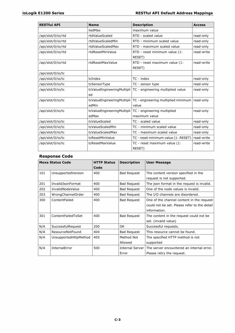
ioLogik E1200 Series RESTful API Default Address Mappings
C-3
RESTful API Name Description Access
liedMax maximum value
/api/slot/0/io/rtd rtdValueScaled RTD - scaled value read-only
/api/slot/0/io/rtd rtdValueScaledMin RTD - minimum scaled value read-only
/api/slot/0/io/rtd rtdValueScaledMax RTD - maximum scaled value read-only
/api/slot/0/io/rtd rtdResetMinValue RTD - reset minimum value (1: RESET)
read-write
/api/slot/0/io/rtd rtdResetMaxValue RTD - reset maximum value (1: RESET)
read-write
/api/slot/0/io/tc
/api/slot/0/io/tc tcIndex TC - index read-only
/api/slot/0/io/tc tcSensorType TC - sensor type read-only
/api/slot/0/io/tc tcValueEngineeringMultiplied
TC - engineering multiplied value read-only
/api/slot/0/io/tc tcValueEngineeringMultipliedMin
TC - engineering multiplied minimum value
read-only
/api/slot/0/io/tc tcValueEngineeringMultipliedMax
TC - engineering multiplied maximum value
read-only
/api/slot/0/io/tc tcValueScaled TC - scaled value read-only
/api/slot/0/io/tc tcValueScaledMin TC - minimum scaled value read-only
/api/slot/0/io/tc tcValueScaledMax TC - maximum scaled value read-only
/api/slot/0/io/tc tcResetMinValue TC - reset minimum value (1: RESET) read-write
/api/slot/0/io/tc tcResetMaxValue TC - reset maximum value (1: RESET)
read-write
Response Code Moxa Status Code HTTP Status
Code Description User Message
101 UnsupportedVersion 400 Bad Request The content version specified in the request is not supported.
201 InvalidJsonFormat 400 Bad Request The json format in the request is invalid.
202 InvalidNodeValue 400 Bad Request One of the node values is invalid.
203 WrongChannelOrder 400 Bad Request The I/O channels are disordered.
300 ContentFailed 400 Bad Request One of the channel content in the request could not be set. Please refer to the detail information.
301 ContentFailedToSet 400 Bad Request The content in the request could not be set. (invalid value)
N/A SuccessfulRequest 200 OK Successful requests.
N/A ResourceNotFound 404 Bad Request This resource cannot be found.
N/A UnsupportedHttpMethod 405 Method Not Allowed
The specified HTTP method is not supported
N/A InternalError 500 Internal Server Error
The server encountered an internal error. Please retry the request.
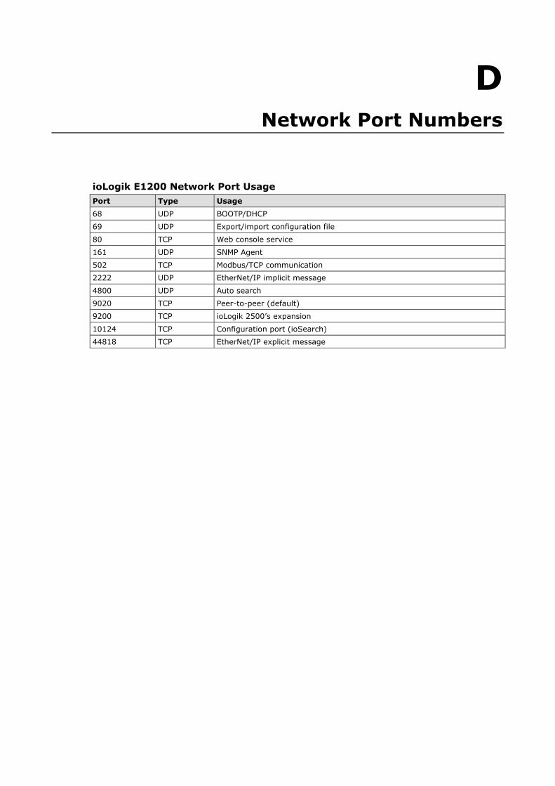
D D. Network Port Numbers
ioLogik E1200 Network Port Usage Port Type Usage
68 UDP BOOTP/DHCP
69 UDP Export/import configuration file
80 TCP Web console service
161 UDP SNMP Agent
502 TCP Modbus/TCP communication
2222 UDP EtherNet/IP implicit message
4800 UDP Auto search
9020 TCP Peer-to-peer (default)
9200 TCP ioLogik 2500’s expansion
10124 TCP Configuration port (ioSearch)
44818 TCP EtherNet/IP explicit message
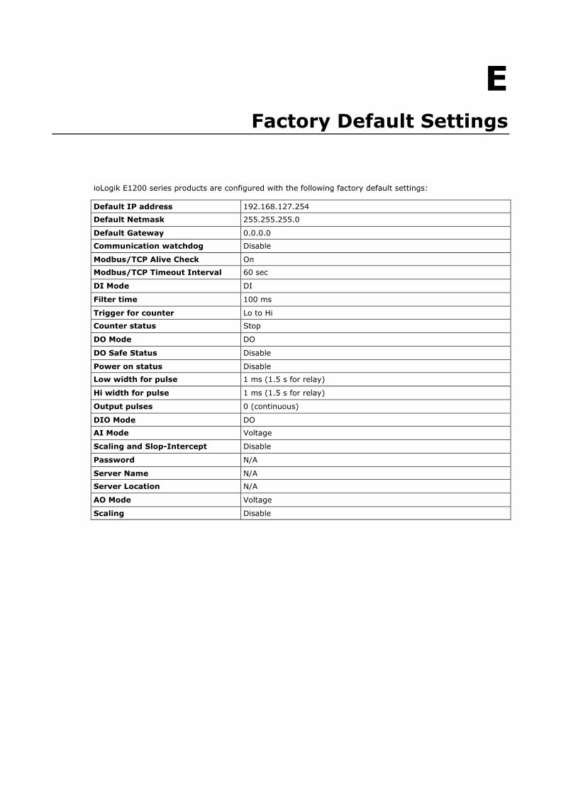
E E. Factory Default Settings
ioLogik E1200 series products are configured with the following factory default settings:
Default IP address 192.168.127.254
Default Netmask 255.255.255.0
Default Gateway 0.0.0.0
Communication watchdog Disable
Modbus/TCP Alive Check On
Modbus/TCP Timeout Interval 60 sec
DI Mode DI
Filter time 100 ms
Trigger for counter Lo to Hi
Counter status Stop
DO Mode DO
DO Safe Status Disable
Power on status Disable
Low width for pulse 1 ms (1.5 s for relay)
Hi width for pulse 1 ms (1.5 s for relay)
Output pulses 0 (continuous)
DIO Mode DO
AI Mode Voltage
Scaling and Slop-Intercept Disable
Password N/A
Server Name N/A
Server Location N/A
AO Mode Voltage
Scaling Disable
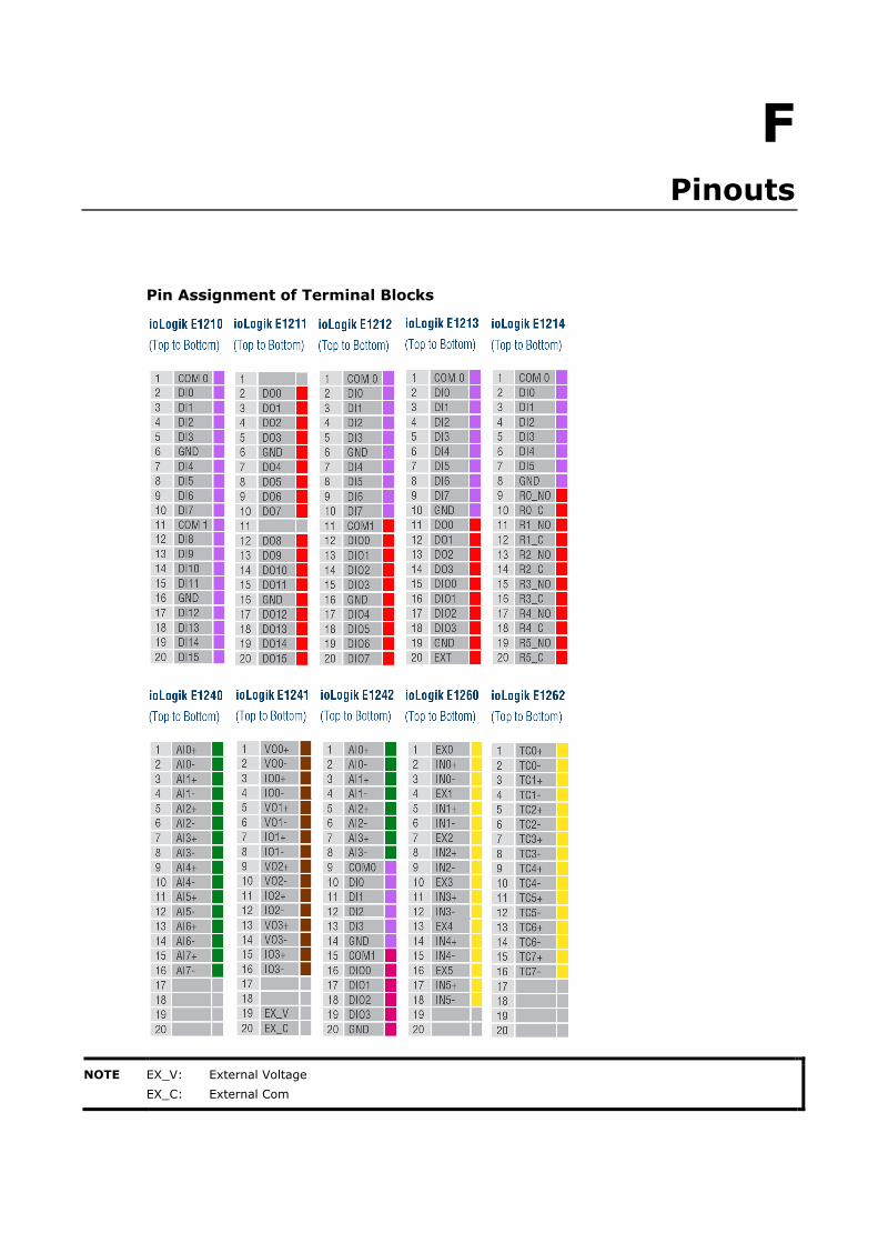
F F. Pinouts
Pin Assignment of Terminal Blocks
NOTE EX_V: External Voltage EX_C: External Com

G G. FCC Interference Statement
Federal Communication Commission Warning! This equipment has been tested and found to comply with the limits for a Class A digital device, pursuant to part 15 of the FCC Rules. Operation is subject to the following two conditions: (1) This device may not cause harmful interference, and (2) this device must accept any interference received, including interference that may cause undesired operation.
These limits are designed to provide reasonable protection against harmful interference when the equipment is operated in a commercial environment. This equipment generates, uses, and can radiate radio frequency energy and, if not installed and used in accordance with the instruction manual, may cause harmful interference to radio communications. Operation of this equipment in a residential area is likely to cause harmful interference in which case the user will be required to correct the interference at his own expense.

H H. European Community (CE)
This is a Class A product. In a domestic environment, this product may cause radio interference in which case the user may be required to take adequate measures.


