
IOL Power Calculation, Correction of Defocus - CH 4
18
Intraocular Lens Power Calculations: Correction of Defocus Jack T. Holladay Financial interest: Dr. Holladay is author of the Holladay formula and provides consultation for A-scan companies that use his formula. CORE MESSAGES 2 The improvements in IOL power calculations over the past 30 years are a result of improving the predictability of the variable effective lens position. 2 The intraocular power calculations for clear lensectomy are no different than the calculations when a cataract is present. 2 Determining the corneal power in patients who have had prior ker- atorefractive surgery is difficult and is the determining factor in the accuracy of the predicted refraction following cataract surgery. 2 The third-generation IOL calculation formulas (Holladay 1, Hoffer Q and the SRK/T) and the new Holladay 2 are much more accurate than previous formulas, especially in unusual eyes. 2 In cases where no power is being removed from the eye, such as secondary implant in aphakia, piggyback IOL in pseudophakia or a minus IOL in the anterior chamber of a phakic patient, the necessary IOL power for a desired postoperative refraction can be calculated from the corneal power and preoperative refraction – the axial length is not necessary. 2 In patients with a significant residual refractive error following the primary IOL implant, it is often easier surgically and more pre- dictable optically to leave the primary implant in place and calcu- late the secondary piggyback IOL power to achieve the desired refraction. 4
Transcript of IOL Power Calculation, Correction of Defocus - CH 4

Intraocular Lens Power Calculations:Correction of Defocus
Jack T. Holladay
Financial interest: Dr. Holladay is author of the Holladay formula and provides consultation for A-scan companies that use his formula.
CORE MESSAGES
2 The improvements in IOL power calculations over the past 30 yearsare a result of improving the predictability of the variable effectivelens position.
2 The intraocular power calculations for clear lensectomy are nodifferent than the calculations when a cataract is present.
2 Determining the corneal power in patients who have had prior ker-atorefractive surgery is difficult and is the determining factor in theaccuracy of the predicted refraction following cataract surgery.
2 The third-generation IOL calculation formulas (Holladay 1, Hoffer Qand the SRK/T) and the new Holladay 2 are much more accuratethan previous formulas, especially in unusual eyes.
2 In cases where no power is being removed from the eye, such assecondary implant in aphakia, piggyback IOL in pseudophakia or aminus IOL in the anterior chamber of a phakic patient, the necessaryIOL power for a desired postoperative refraction can be calculatedfrom the corneal power and preoperative refraction – the axiallength is not necessary.
2 In patients with a significant residual refractive error following theprimary IOL implant, it is often easier surgically and more pre-dictable optically to leave the primary implant in place and calcu-late the secondary piggyback IOL power to achieve the desiredrefraction.
4
4.1 Introduction
The indications for intraocular lens (IOL)implantation following cataract or clear lens-ectomy have significantly increased. Theseexpanded indications result in more compli-cated cases such as patients with a scleralbuckle, silicone in the vitreous, previousrefractive surgery, piggyback IOLs in nan-ophthalmos, positive and negative secondarypiggyback IOLs and specialty lenses, such asmultifocal and toric IOLs. Techniques for de-termining the proper IOL and power are pre-sented.
Several measurements of the eye are help-ful in determining the appropriate IOL powerto achieve a desired refraction. These meas-urements include central corneal refractivepower (K-readings), axial length (biometry),horizontal corneal diameter (horizontalwhite to white), anterior chamber depth, lensthickness, preoperative refraction and age ofthe patient. The accuracy of predicting thenecessary power of an IOL is directly relatedto the accuracy of these measurements [1, 2].
4.1.1 Theoretical Formulas
Fyodorov first estimated the optical power ofan IOL using vergence formulas in 1967 [3].Between 1972 and 1975, when accurate ultra-sonic A-scan units became commerciallyavailable, several investigators derived andpublished the theoretical vergence formula[4–9]. All of these formulas were identical[10], except for the form in which they werewritten and the choice of various constantssuch as retinal thickness, optical plane of thecornea, and optical plane of the IOL. Theseslightly different constants accounted for lessthan 0.50 diopters in the predicted refraction.The variation in these constants was a resultof differences in lens styles, A-scan units,keratometers, and surgical techniques amongthe investigators.
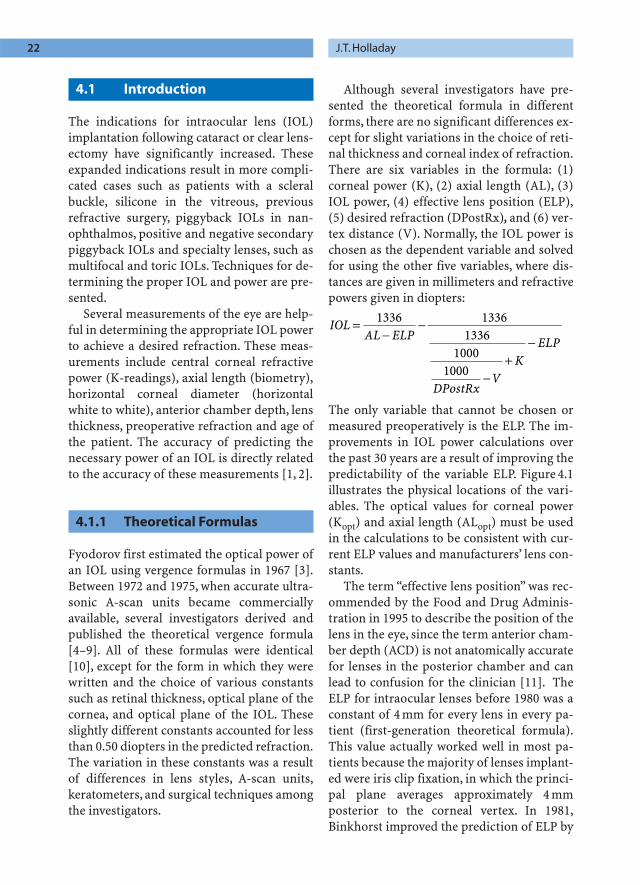
Although several investigators have pre-sented the theoretical formula in differentforms, there are no significant differences ex-cept for slight variations in the choice of reti-nal thickness and corneal index of refraction.There are six variables in the formula: (1)corneal power (K), (2) axial length (AL), (3)IOL power, (4) effective lens position (ELP),(5) desired refraction (DPostRx), and (6) ver-tex distance (V). Normally, the IOL power ischosen as the dependent variable and solvedfor using the other five variables, where dis-tances are given in millimeters and refractivepowers given in diopters:
The only variable that cannot be chosen ormeasured preoperatively is the ELP. The im-provements in IOL power calculations overthe past 30 years are a result of improving thepredictability of the variable ELP. Figure 4.1illustrates the physical locations of the vari-ables. The optical values for corneal power(Kopt) and axial length (ALopt) must be usedin the calculations to be consistent with cur-rent ELP values and manufacturers’ lens con-stants.
The term “effective lens position” was rec-ommended by the Food and Drug Adminis-tration in 1995 to describe the position of thelens in the eye, since the term anterior cham-ber depth (ACD) is not anatomically accuratefor lenses in the posterior chamber and canlead to confusion for the clinician [11]. TheELP for intraocular lenses before 1980 was aconstant of 4 mm for every lens in every pa-tient (first-generation theoretical formula).This value actually worked well in most pa-tients because the majority of lenses implant-ed were iris clip fixation, in which the princi-pal plane averages approximately 4 mmposterior to the corneal vertex. In 1981,Binkhorst improved the prediction of ELP by
IOLAL ELP
DPostRxV
KELP
=−
−
−+
−
1336 13361336
10001000
22 J.T. Holladay

using a single-variable predictor, the axiallength, as a scaling factor for ELP (second-generation theoretical formula) [12]. If thepatient’s axial length was 10% greater thannormal (23.45 mm), he would increase theELP by 10%. The average value of ELP was in-creased to 4.5 mm because the preferred loca-tion of an implant was in the ciliary sulcus,approximately 0.5 mm deeper than the irisplane. Also, most lenses were convex-plano,similar to the shape of the iris-supportedlenses. The average ELP in 1996 has increasedto 5.25 mm. This increased distance has oc-curred primarily for two reasons: the majori-ty of implanted IOLs are biconvex, movingthe principal plane of the lens even deeperinto the eye, and the desired location for thelens is in the capsular bag, which is 0.25 mmdeeper than the ciliary sulcus.
In 1988, we proved [13] that using a two-variable predictor, axial length and keratom-etry, could significantly improve the predic-tion of ELP, particularly in unusual eyes(third-generation theoretical formula). Theoriginal Holladay 1 formula was based on thegeometrical relationships of the anterior seg-ment. Although several investigators havemodified the original two-variable Holladay1 prediction formula, no comprehensivestudies have shown any significant improve-ment using only these two variables.
In 1995, Olsen published a four-variablepredictor that used axial length, keratometry,preoperative anterior chamber depth and
lens thickness [14]. His results did show im-provement over the current two-variable pre-diction formulas. The explanation is verysimple. The more information we have aboutthe anterior segment, the better we can pre-dict the ELP.This explanation is a well-knowntheorem in prediction theory, where the morevariables that can be measured describing anevent, the more precisely one can predict theoutcome.
In a recent study [15], we discovered thatthe anterior segment and posterior segmentof the human eye are often not proportionalin size, causing significant error in the predic-tion of the ELP in extremely short eyes(<20 mm). We found that, even in eyes short-er than 20 mm, the anterior segment wascompletely normal in the majority of cases.Because the axial lengths were so short, thetwo-variable prediction formulas severelyunderestimated the ELP, explaining part ofthe large hyperopic prediction errors withcurrent two-variable prediction formulas.Af-ter recognizing this problem, we began totake additional measurements on extremelyshort and extremely long eyes to determine ifthe prediction of ELP could be improved byknowing more about the anterior segment.Table 4.1 shows the clinical conditions thatillustrate the independence of the anteriorsegment and the axial length.
For 3 years, we gathered data from 35 in-vestigators around the world. Several addi-tional measurements of the eye were taken,
Chapter 4 Intraocular Lens Power Calculations 23
Table 4.1. Clinical conditions demonstrating the independence of the anterior segment and axial length
Anterior segment Size Axial length
Short Normal Long
Small Small eye MicrocorneaNanophthalmos Microcornea +Axial myopia
Normal Axial hyperopia Normal Axial myopia
Large Megalocornea Large eyeAxial hyperopia Megalocornea Buphthalmos
+Axial myopia

but only seven preoperative variables (axiallength, corneal power, horizontal corneal di-ameter, anterior chamber depth, lens thick-ness, preoperative refraction and age) werefound to be useful for significantly improvingthe prediction of ELP in eyes ranging from 15to 35 mm.
The improved prediction of ELP is not to-tally due to the formula, but is also a functionof the technical skills of the surgeons who areconsistently implanting the lenses in the cap-sular bag. A 20-D IOL that is 0.5 mm axiallydisplaced from the predicted ELP will resultin an approximately 1.0-D error in the stabi-lized postoperative refraction. However,when using piggyback lenses totaling 60 D,the same axial displacement of 0.5 mm willcause a 3-D refractive surprise; the error is di-rectly proportional to the implanted lenspower. This direct relationship to the lenspower is why the problem is much less evi-dent in extremely long eyes, since the im-planted IOL is either low plus or minus toachieve emmetropia following cataract ex-traction.
The Holladay 2 formula provides morepredictable results in unusual eyes. Oncethese additional measurements become rou-tine among clinicians, a new flurry of predic-tion formulas using seven or more variableswill emerge, similar to the activity followingour two-variable prediction formula in 1988.The standard of care will reach a new level ofprediction accuracy for extremely unusualeyes, just as it has for normal eyes. Calcula-tions on patients with axial lengths between22 and 25 mm with corneal powers between42 and 46 D will do well with current third-generation formulas (Holladay, SRK/T [16,17]). In cases outside this range, the Holladay2 should be used to assure accuracy.
4.2 Normal Cornea with no Previous Kerato-refractive Surgery
4.2.1 Clear Lensectomy for High Myopia and Hyperopia
The intraocular power calculations for clearlensectomy are no different than the calcula-tions when a cataract is present. The patientsare usually much younger, however, and theloss of accommodation should be discussedthoroughly. The actual desired postoperativerefraction should also be discussed, since asmall degree of myopia (–0.50 D) may be de-sirable to someone with no accommodationto reduce their dependence on spectacles.
This procedure is usually reserved for pa-tients who are outside the range for otherforms of refractive surgery. Consequently, themeasurements of axial length, keratometry,etc., are usually quite different from those ofthe typical cataract patient because of the ex-ceptionally large refractive error and youngerage of the patient. In most of the cases withhigh myopia, the axial lengths are extremelylong (>26 mm). In cases of high hyperopia,the axial lengths are very short (<21 mm).
In patients with myopia exceeding 20 D,re-moving the clear lens often results in postop-erative refractions near emmetropia with noimplant. The exact result depends on thepower of the cornea and the axial length. Therecommended lens powers usually rangefrom –10 D to +10 D in the majority of thesecases. The correct axial length measurementis very difficult to obtain in these cases be-cause of the abnormal anatomy of the poste-rior pole. Staphylomas are often present inthese eyes, and the macula is often not at thelocation in the posterior pole where the A-scan measures the axial length. In these casesit is recommended that a B-scan be per-formed to locate the macula (fovea) andrecheck the measurement determined by A-scan. I have personally seen 3- to 4-D surpris-
24 J.T. Holladay

es because the macula was on the edge of thestaphyloma, and the A-scan measured to thedeepest part of the staphyloma. Such an errorresults in a hyperopic surprise because thedistance to the macula is much shorter thanthe distance to the center of the staphyloma.The third-generation theoretical formulasyield excellent results if the axial lengthmeasurement is accurate and stable.
In patients with hyperopia exceeding +8 D,the axial lengths are often less than 21 mmand require lens powers that exceed the nor-mal range (>34 D). In these cases, piggybacklenses are necessary to achieve emmetropia[15]. The only formula available at this timein these eyes is the Holladay 2. If the requiredlens power is less than or equal to 34 D, thepiggyback lenses are not required and third-generation theoretical formulas may be used.
4.2.2 Piggyback IOLs to Achieve Powers Above 34 D
Patients with axial lengths shorter than21 mm should be calculated using the Holla-day 2 formula. In these cases, the size of theanterior segment has been shown to be unre-lated to the axial length [15]. In many of thesecases the anterior segment size is normal andonly the posterior segment is abnormallyshort. In a few cases, however, the anteriorsegment is proportionately small to the axiallength (nanophthalmos). The differences inthe size of the anterior segment in these casescan cause an average of 5-D hyperopic errorwith third-generation formulas because theypredict the depth of the anterior chamber tobe very shallow. Using the newer formula canreduce the prediction error in these eyes toless than 1 D.
Accurate measurements of axial lengthand corneal power are especially importantin these cases because any error is magnifiedby the extreme dioptric powers of the IOLs.Placement of both lenses in the bag with thehaptics aligned is essential. Inadvertently
placing one lens in the bag and the other inthe sulcus can cause a 4 diopter refractive sur-prise.
4.3 Patients with Previous Kerato-refractive Surgery
4.3.1 Background
The number of patients who have had kera-torefractive surgery (radial keratotomy – RK,photorefractive keratectomy – PRK, or laser-assisted in-situ keratomileusis – LASIK) hasbeen steadily increasing over the past 20years. With the advent of the excimer laser,these numbers are predicted to increase dra-matically. Determining their corneal poweraccurately is difficult and usually is the deter-mining factor in the accuracy of the predict-ed refraction following cataract surgery. Pro-viding this group of patients the sameaccuracy with intraocular lens power calcula-tions as we have provided our standardcataract patients presents an especially diffi-cult challenge for the clinician.
4.3.2 Preoperative Evaluation
4.3.2.1 Corneal Evaluation
At present, far more patients have had RKthan PRK and LASIK combined. Also, ourlong-term follow-up of RK patients is muchgreater. The long-term studies of RK patientsreveal that some have hyperopic shifts intheir refraction and develop progressiveagainst-the-rule astigmatism [18]. The long-term refractive changes in PRK and LASIKare unknown, except for the regression effectfollowing attempted PRK corrections exceed-ing 8 diopters.No matter which procedure thepatient has had, the stability or instability ofthe refraction must be determined. Thisdetermination includes daily fluctuations
Chapter 4 Intraocular Lens Power Calculations 25

from morning to night as well as long-termchanges over the past few years. Each of thesefactors must be used in determining the de-sired postoperative target refraction and toprepare the patient for the visual changes andrealistic expectations following the proce-dure.
In all of these cases, biomicrosopy, retino-scopy, corneal topography and endothelialcell counts are recommended. These firstthree tests are primarily directed at evaluat-ing the amount of irregular astigmatism. Thisdetermination is extremely important pre-operatively because the irregular astigma-tism may be contributing to the reduced vi-sion as well as the cataract. The irregularastigmatism may also be the limiting factorin the patient’s vision following cataract sur-gery. The endothelial cell count is necessaryto recognize any patients with low cell countsfrom the previous surgery who may be athigher risk for corneal decompensation orprolonged visual recovery.
The potential acuity meter (PAM), superpinhole and hard contact lens trial are oftenhelpful as secondary tests in determining therespective contribution to reduced vision bythe cataract and the corneal irregular astig-matism. The patient should also be informedthat only the glare from the cataract will beeliminated; any glare from the keratorefrac-tive procedure will essentially remain un-changed.
4.3.2.2 Methods of Determining Corneal Power
Accurately determining the central cornealrefractive power is the most important anddifficult part of the entire intraocular lenscalculation process. The explanation is quitesimple. Our current instruments for measur-ing corneal power make too many incorrectassumptions with corneas that have irregularastigmatism. The cornea can no longer becompared to a sphere centrally, the posterior
radius of the cornea is no longer 1.2 mmsteeper than the anterior corneal radius, etc.Because of these limitations, the calculatedmethod and the trial hard contact lensmethod are most accurate, followed bycorneal topography, automated keratometryand finally manual keratometry.
4.3.2.2.1 Calculation Method
For the calculation method, three parametersmust be known: the K-readings and refrac-tion before the keratorefractive procedureand the stabilized refraction after the kera-torefractive procedure. It is important that thestabilized postoperative refraction be meas-ured before any myopic shifts from nuclearsclerotic cataracts occur. It is also possible forposterior subcapsular cataracts to cause anapparent myopic shift, similar to capsularopacification, where the patient wants moreminus in the refraction to make the letters ap-pear smaller and darker. The concept that wedescribed in 1989 subtracts the change in re-fraction due to the keratorefractive proce-dure at the corneal plane from the original K-readings before the procedure to arrive at acalculated postoperative K-reading [19]. Thismethod is usually the most accurate becausethe preoperative K-readings and refractionare usually accurate to ±0.25 D. An examplecalculation to illustrate the calculationmethod is given.
Example:∑ Mean preoperative K = 42.50 @ 90∞
and 41.50 @ 180∞ = 42.00 D∑ Preoperative refraction =
–10.00 + 1.00 ¥ 90∞, Vertex = 14 mm∑ Postoperative refraction =
–0.25 + 1.00 ¥ 90∞, Vertex = 14 mm
Step 1. Calculate the spheroequivalent refrac-tion for refractions at the corneal plane(SEQC) from the spheroequivalent refrac-tions at the spectacle plane (SEQS) at a givenvertex, where
26 J.T. Holladay

a. SEQ = Sphere + 0.5 (Cylinder)
Calculation for preoperative spheroequiva-lent refraction at corneal plane
a. SEQR = –10.00 + 0.5 * (1.00) = –9.50 D
Calculation for postoperative spheroequiva-lent refraction at corneal plane
a. SEQR = –0.25 + 0.5 * (1.00) = +0.25 D
Step 2. Calculate the change in refraction atthe corneal plane.
Change in refraction = preoperative SEQC– postoperative SEQC
Change in refraction = –8.38 – (+0.025) = –8.68 DStep 3. Determine calculated postoperativecorneal refractive power.
Mean postoperative K = mean preoperative K– change in refraction at corneal plane
Mean postoperative K = 42.00 – 8.68 = 33.32 D
This value is the calculated central power ofthe cornea following the keratorefractiveprocedure. For IOL programs requiring twoK-readings, this value would be entered twice.
4.3.2.2.2 Trial Hard Contact Lens Method
The trial hard contact lens method requires aplano hard contact lens with a known basecurve and a patient whose cataract does notprevent them from being refracted to approx-imately ±0.50 D. This tolerance usually re-
b. DSEQC =
+−
= +100010000 25
140 25
.
.
b. DSEQC =
−−
= −100010009 50
148 38
.
.
b.
S
SEQ
SEQVertex mm
C =−
10001000 ( )
quires a visual acuity of better than 20/80.The patient’s spheroequivalent refraction isdetermined by normal refraction. The refrac-tion is then repeated with the hard contactlens in place. If the spheroequivalent refrac-tion does not change with the contact lens,the patient’s cornea must have the same pow-er as the base curve of the plano contact lens.If the patient has a myopic shift in the refrac-tion with the contact lens, the base curve ofthe contact lens is stronger than the cornea bythe amount of the shift. If there is a hyperop-ic shift in the refraction with the contact lens,the base curve of the contact lens is weakerthan the cornea by the amount of the shift.
Example:The patient has a current spheroequiva-
lent refraction of +0.25 D. With a plano hardcontact lens with a base curve of 35.00 Dplaced on the cornea, the spherical refractionchanges to –2.00 D. Since the patient had amyopic shift with the contact lens, the corneamust be weaker than the base curve of thecontact lens by 2.25 D. Therefore, the corneamust be 32.75 D (35.00–2.25), which is slight-ly different than the value obtained by the cal-culation method. In equation form, we have
SEQ Refraction without hard contact lens =+0.25 D
Base curve of plano hard contact lens =35.00 D
SEQ Refraction with hard contact lens =–2.00 D
Change in refraction = –2.00 – ( +0.25) = –2.25 D (myopic shift)
Mean corneal power = base curve of planohard contact lens + change in refraction
Mean corneal power = 35.00 + –2.25
Mean corneal power = 32.75 D
NB: This method is limited by the accuracy ofthe refractions, which may be limited by thecataract.
Chapter 4 Intraocular Lens Power Calculations 27

4.3.2.2.3 Corneal Topography
Current corneal topography units measuremore than 5,000 points over the entire corneaand more than 1,000 points within the central3 mm. This additional information providesgreater accuracy in determining the power ofcorneas with irregular astigmatism com-pared to keratometers. The computer in to-pography units allows the measurement toaccount for the Stiles-Crawford effect, actualpupil size, etc. These algorithms allow a veryaccurate determination of the anterior sur-face of the cornea [20]. They provide no in-formation, however, about the posterior sur-face of the cornea. In order to determineaccurately the total power of the cornea, thepower of both surfaces must be known.
In normal corneas that have not under-gone keratorefractive surgery, the posteriorradius of curvature of the cornea averages1.2 mm less than the anterior surface. In aperson with an anterior corneal radius of7.5 mm using the Standardized KeratometricIndex of Refraction of 1.3375, the cornealpower would be 45.00 D. Several studies haveshown that this power overestimates the totalpower of the cornea by approximately 0.56 D.Hence, most IOL calculations today use a netindex of refraction of 1.3333 (4/3) and the an-terior radius of the cornea to calculate the netpower of the cornea. Using this lower value,the total power of a cornea with an anteriorradius of 7.5 mm would be 44.44 D. This indexof refraction has provided excellent results innormal corneas for IOL calculations.
Following keratorefractive surgery, the as-sumptions that the central cornea can be ap-proximated by a sphere (no significant irreg-ular astigmatism or asphericity) and that the posterior corneal radius of curvature is1.2 mm less than the anterior radius are nolonger true. Corneal topography instrumentscan account for the changes in the anteriorsurface, but are unable to account for any dif-ferences in the relationship to the posteriorradius of curvature. In RK, the mechanism of
having a peripheral bulge and central flatten-ing apparently causes similar changes in boththe anterior and posterior radius of curvatureso that using the net index of refraction forthe cornea (4/3) usually gives fairly accurateresults, particularly for optical zones largerthan 4–5 mm. In RKs with optical zones of3 mm or less, the accuracy of the predictedcorneal power diminishes.Whether this inac-curacy is due to the additional central irregu-larity with small optical zones or the differ-ence in the relationship between the front andback radius of the cornea is unknown at thistime. Studies measuring the posterior radiusof the cornea in these patients will be neces-sary to answer this question.
In PRK and LASIK, the inaccuracies ofthese instruments to measure the net cornealpower is almost entirely due to the change inthe relationship of the radii of the front andback of the cornea, since the irregular astig-matism in the central 3-mm zone is usuallyminimal. In these two procedures, the anteri-or surface of the cornea is flattened with littleor no effect on the posterior radius. Using anet index of refraction (4/3) will overestimatethe power of the cornea by 14% of the changeinduced by the PRK or LASIK, i.e. if the pa-tient had a 7-D change in the refraction at thecorneal plane from a PRK or LASIK withspherical preoperative K-readings of 44 D, theactual power of the cornea is 37 D and the to-pography units will give 38 D. If a 14-Dchange in the refraction has occurred at thecorneal plane, the topography units will over-estimate the power of the cornea by 2diopters.
In summary, the corneal topography unitsdo not provide accurate central corneal pow-er following PRK, LASIK and in RKs with op-tical zones of 3 mm or less. In RKs with largeroptical zones, the topography units becomemore reliable. The calculation method andhard contact lens trial are always more reli-able.
28 J.T. Holladay

4.3.2.2.4 Automated Keratometry
Automated keratometers are usually more ac-curate than manual keratometers in corneaswith small optical zone (£3 mm) RKs becausethey sample a smaller central area of thecornea (nominally 2.6 mm). In addition, theautomated instruments often have additionaleccentric fixation targets that provide moreinformation about the paracentral cornea.When a measurement error on an RK corneais made, the instrument almost always gives acentral corneal power that is greater than thetrue refractive power of the cornea.This erroroccurs because the samples at 2.6 mm arevery close to the paracentral knee of the RK.The smaller the optical zone and the greaterthe number of the RK incisions, the greaterthe probability and magnitude of the error.Most of the automated instruments have reli-ability factors that are given for each meas-urement, helping the clinician decide on thereliability in the measurement.
Automated keratometry measurementsfollowing LASIK or PRK yield accurate meas-urements of the front radius of the cornea be-cause the transition areas are far outside the2.6-mm zone that is measured. The measure-ments are still not accurate, however, becausethe assumed net index of refraction (4/3) isno longer appropriate for the new relation-ship of the front and back radius of thecornea after PRK or LASIK, just as with thetopographic instruments. The change in cen-tral corneal power as measured by the ker-atometer from PRK or LASIK must be in-creased by 14% to determine the actualrefractive change at the plane of the cornea.Hence, the automated keratometer will over-estimate the power of the cornea proportion-al to the amount of PRK or LASIK performed.
4.3.2.2.5 Manual Keratometry
Manual keratometers are the least accurate inmeasuring central corneal power followingkeratorefractive procedures, because the area
that they measure is usually larger than auto-mated keratometers at 3.2 mm in diameter.Therefore, measurements in this area are ex-tremely unreliable for RK corneas with opti-cal zones £4 mm. The one advantage with themanual keratometer is that the examiner isactually able to see the reflected mires and theamount of irregularity present. Seeing themires does not help get a better measure-ment, but does allow the observer to discountthe measurement as unreliable.
The manual keratometer has the sameproblem with PRK and LASIK as topogra-phers and automated keratometers, and istherefore no less accurate. The manual ker-atometer will overestimate the change in thecentral refractive power of the cornea by 14%following PRK and LASIK.
4.3.2.3 Choosing the Desired Postoperative Refraction Target
Determining the desired postoperative re-fractive target is no different than for otherpatients with cataracts, where the refractivestatus and the presence of a cataract in theother eye are the major determining factors.A complete discussion of avoiding refractiveproblems with cataract surgery is beyond thescope of this text, and is thoroughly discussedin the reference given [21].A short discussionof the major factors will follow.
If the patient has binocular cataracts, thedecision is much easier because the refractivestatus of both eyes can be changed. The mostimportant decision is whether the patientprefers to be myopic and read without glass-es, or near emmetropic and drive withoutglasses. In some cases the surgeon and pa-tient may choose the intermediate distance(–1.00 D) for the best compromise. Targetingfor monovision is certainly acceptable, pro-vided the patient has successfully utilizedmonovision in the past. Trying to producemonovision in a patient who has never expe-
Chapter 4 Intraocular Lens Power Calculations 29

rienced this condition may cause intolerableanisometropia and require further surgery.
Monocular cataracts allow fewer choicesfor the desired postoperative refraction, be-cause the refractive status of the other eye isfixed. The general rule is that the operativeeye must be within 2 D of the non-operativeeye in order to avoid intolerable anisome-tropia. In most cases this means matching the other eye or targeting for up to 2 D near-er emmetropia, i.e. if the non-operative eye is–5.00 D, the target would be –3.00 D for theoperative eye. If the patient is successfullywearing a contact lens in the non-operativeeye or has already demonstrated his ability toaccept monovision, an exception can be madeto the general rule. It should always bestressed, however, that should the patient beunable to continue wearing a contact, the nec-essary glasses for binocular correction maybe intolerable and additional refractive sur-gery may be required.
4.3.2.4 Special Limitations of Intraocular Lens Power Calculation Formulas
As discussed previously, the third-generationformulas (Holladay 1, Hoffer Q and theSRK/T) and the new Holladay 2 are muchmore accurate than previous formulas themore unusual the eye. Older formulas such asthe SRK1, SRK2 and Binkhorst 1 should notbe used in these cases. None of these formu-las will give the desired result if the centralcorneal power is measured incorrectly. Theresulting errors are almost always in the hy-peropic direction following keratorefractivesurgery, because the measured corneal pow-ers are usually greater than the true refractivepower of the cornea.
To complicate matters further, the newerformulas often use keratometry as one of thepredictors to estimate the ELP of the intraoc-ular lens. In patients who have had keratore-fractive surgery, the corneal power is usually
much flatter than normal and certainly flatterthan before the keratorefractive procedure. Inshort, a patient with a 38-D cornea withoutkeratorefractive surgery would not be expect-ed to be similar to a patient with a 38-Dcornea with keratorefractive surgery. NewerIOL calculation programs are now being de-veloped to handle these situations and willimprove our predictability in these cases.
4.3.3 Intraoperative Evaluation
4.3.3.1 Intraoperative Visualization and Corneal Protection
Intraoperative visualization is usually moredifficult in patients with previous RK than inthe normal cataract patient and is somewhatsimilar to severe arcus senilis or other condi-tions that cause peripheral corneal haze. Thesurgeon should be prepared for this addition-al difficulty by making sure that the patient islined up to visualize the cataract through theoptical zone. This usually means lining themicroscope perpendicular to the center of thecornea, so that the surgeon is looking direct-ly through the optical zone at the center of thecataract. When removing the peripheral cor-tex, the eye can be rotated so that visualiza-tion of the periphery is through the centraloptical zone. It is also prudent to coat the en-dothelium with viscoelastic to minimize anyendothelial cell loss, since the keratorefrac-tive procedure may have caused some priorloss.
4.3.3.2 Intraoperative Autorefractor/Retinoscopy
Large refractive surprises can be avoided by intraoperative retinoscopy or hand-heldautorefractors. These refractions should notbe relied upon, however, for fine tuning theintraocular lens power, since there are manyfactors at surgery that may change in the
30 J.T. Holladay

postoperative period. Factors such as thepressure from the lid speculum,axial positionof the intraocular lens, intraocular pressure,etc. may cause the intraoperative refraction tobe different than the final stabilized postop-erative refraction. If the intraoperative refrac-tion is within 2 D of the target refraction, nolens exchanges should be considered unlessintraoperative keratometry can also be per-formed.
4.3.4 Postoperative Evaluation
4.3.4.1 Refraction on the First Postoperative Day
On the first postoperative day followingcataract surgery, patients who previouslyhave had RK usually have a hyperopic shift,similar to the first postoperative day follow-ing their RK. This phenomenon is primarilydue to the transient corneal edema that usu-ally exaggerates the RK effect. These patientsalso exhibit the same daily fluctuations dur-ing the early postoperative period after theircataract surgery as they did after the RK. Usu-ally this daily shift is in a myopic directionduring the day due to the regression ofcorneal edema after awakening in the morn-ing [22]. Because the refractive changes areexpected and vary significantly among pa-tients, no lens exchange should be contem-plated until after the first postoperative weekor until after the refraction has stabilized,whichever is longer.
Very few results of cataract surgery follow-ing PRK and LASIK are available. In the fewcases that have been performed, the hyperop-ic shift on the first day and daily fluctuationsappear to be much less, similar to the earlypostoperative period following these proce-dures. In most cases the stability of the corneamakes these cases no different than patientswho have not had keratorefractive surgery.
4.3.4.2 Long-term Results
Long-term results of cataract surgery follow-ing RK are very good. The long-term hyper-opic shifts and development of against-the-rule astigmatism over time following cataractsurgery should be the same as in the long-term studies following RK. The problemswith glare and starburst patterns are usuallyminimal because the patients have had to ad-just to these unwanted optical images follow-ing the initial RK. If the patient’s primarycomplaint before cataract surgery is glare andstarbursts, it should be made clear to him thatonly the glare due to the cataract will be re-moved by surgery, and the symptoms that aredue to the RK will remain unchanged.
Long-term results following PRK andLASIK are non-existent. Since there are nosigns of hyperopic drifts or development ofagainst-the-rule astigmatism in the 5-yearstudies following PRK, one would not expectto see these changes. However, the early stud-ies following RK did not suggest any of theselong-term changes either. Only time will tellwhether central haze, irregular astigmatism,etc. will be problems that develop in the fu-ture.
4.4 Patients with Previous Scleral Buckling and/or Silicone in the Vitreous Cavity
Patients who have undergone scleral buck-ling usually have an increase in their axiallength by an average of 0.8 mm, which usual-ly results in an approximate 2.4 diopter my-opic shift. This value may range from 0 to2.0 mm, depending on the location and ten-sion on the encircling band. If no silicone oilhas been placed in the vitreous cavity, meas-uring the axial length is no different than inpatients with high myopia. Choosing the tar-get postoperative refraction is also no differ-ent than for the normal patient, although
Chapter 4 Intraocular Lens Power Calculations 31

many of these patients prefer myopia since inmany cases this has been the refraction mostof their life.
If the patient does have a longer axiallength in the eye with the scleral buckle,matching the refraction to the other eye willrequire a weaker power IOL.Although the pa-tient may experience aniseikonia (image sizedisparity, larger in the eye with the buckle),he will usually adjust to this difference within2–3 weeks. If the lens power is chosen to elim-inate image size disparity by choosing astronger lens to make the patient more my-opic so that the spectacle has more minus, theimage sizes are nearly the same (iseikonia).The problem is that the anisometropia (un-equal refractive errors) induces a prism dif-ference that causes diplopia when reading.The patient cannot adjust to the diplopia andeither the spectacles must be slabbed off, acontact lens must be worn, a secondary pig-gyback IOL must be implanted, or a lens ex-change must be performed.
If silicone has been placed in the vitreouscavity, the case becomes much more complex.An accurate axial length cannot be measuredwith silicone in the vitreous cavity. The oil isso dense that the ultrasound echoes rarelycome from the retina because they are so at-tenuated. The measured axial length is far tooshort, even when the measurement is adjust-ed for the ultrasound speed in silicone oil. It isrecommended that the axial length from theother eye be used in these cases and 0.8 mmadded to this length of the cataractous eye if ascleral buckle has been performed. If botheyes have silicone in the vitreous cavity andpreoperative axial lengths were not meas-ured, one simply uses a standard lens power,adjusting up or down depending on the pa-tient’s most recent refraction before any sur-gery. Many retina surgeons are now measur-ing the axial length before using silicone oil toavoid this dilemma.
If the axial length is known in the eye withsilicone, the IOL power can be determined inthe normal manner, except for adjusting for
the index of refraction difference between sil-icone and vitreous. It is recommended thatconvexo-plano IOLs be used in these cases tominimize the effect of the silicone reducingthe effective power of the back surface of theIOL.When convexo-plano lenses are used, theaverage additional power required with sili-cone in the vitreous cavity is approximately3–5 diopters. If a lens with power on the pos-terior surface is used, the required power ismuch greater and ranges from 5 to 10diopters, depending on the power of the backsurface.
An additional benefit of the convexo-plano lens is that it minimizes the change inrefraction if the silicone oil is removed. It isbest to leave the patient near plano if it is pos-sible that the silicone IOL will be removed,since the shift when the oil is removed will al-ways be in a myopic direction. The formulasfor calculating the exact lens power, with anaccurate axial length and silicone in the vitre-ous cavity, are too complex for this discus-sion, but several computer programs nowhave the appropriate formulas to performthis calculation exactly. Unfortunately, inmany of these cases the best corrected visionis poor,making exact calculations resulting invery little additional benefit to the patient.
4.5 IOL Calculations Using K-readings and Preoperative Refraction
4.5.1 Formula and Rationale for Using Preoperative Refraction vs. Axial Length
In a standard cataract removal with IOL im-plantation, the preoperative refraction is notvery helpful in calculating the power of theimplant because the crystalline lens will beremoved, so dioptric power is being removedand then replaced. In cases where no power isbeing removed from the eye, such as second-ary implant in aphakia, piggyback IOL inpseudophakia or a minus IOL in the anterior
32 J.T. Holladay

chamber of a phakic patient, the necessaryIOL power for a desired postoperative refrac-tion can be calculated from the corneal pow-er and preoperative refraction – the axial
length is not necessary. The formula for cal-culating the necessary IOL power is givenbelow [23]:
Chapter 4 Intraocular Lens Power Calculations 33
Fig. 4.1.Standardized 72 y/ophakic schematic eye
Fig. 4.2.Standardized 20 y/ophakic schematic eye

where ELP = expected lens position in mm(distance from corneal vertex to principalplane of intraocular lens), IOL = intraocularlens power in diopters, K = net corneal powerin diopters, PreRx = preoperative refractionin diopters, DPostRx = desired postoperativerefraction in diopters, and V = vertex dis-tance in mm of refractions. The physical loca-tion of these variables is identical to those inFig. 4.1. The standardized 20-year-old phakicschematic eye is shown in Fig. 4.2.
4.5.2 Example Cases Calculating the IOL Power from Preoperative Refraction
As mentioned above, the appropriate casesfor using the preoperative refraction andcorneal power include: (1) secondary implantin aphakia, (2) secondary piggyback IOL in pseudophakia and (3) a minus anteriorchamber IOL in a high myopic phakic pa-tient. In each of these cases, no dioptric pow-er is being removed from the eye, so the prob-lem is simply to find the intraocular lens at agiven distance behind the cornea ELP that isequivalent to the spectacle lens at a givenvertex distance in front of the cornea. If em-metropia is not desired,an additional term,thedesired postoperative refraction (DPostRx),must be included. The formulas for calculat-ing the predicted refraction and the back-cal-culation of the ELP are given in the referenceand will not be repeated here [23].
4.5.2.1 Example: Secondary Implant for Aphakia
The patient is 72 years old and is aphakic inthe right eye and pseudophakic in the left eye.
The right eye can no longer tolerate an apha-kic contact lens. The capsule in the right eyeis intact and a posterior chamber intraocularlens is desired. The patient is –0.50 D in theleft eye and would like to be the same in theright eye.
Mean keratometric K = 45.00 D
Aphakic refraction = +12.00 sphere @ vertex of 14 mm
Manufacturer’s ACD lens constant = 5.25 mm
Desired postoperative refraction = –0.50 D
Each of the values above can be substituted inthe refraction formula above, except for themanufacturer’s ACD and the measured K-reading. The labeled values on intraocularlens boxes are primarily for lenses implantedin the bag. Since this lens is intended for thesulcus, 0.25 mm should be subtracted from5.25 mm to arrive at the equivalent constantfor the sulcus. The ELP is therefore 5.00 mm.The K-reading must be converted from themeasured keratometric K-reading (n =1.3375) to the net K-reading (n = 4/3), for thereasons described previously under cornealtopography. The conversion is performed bymultiplying the measured K-reading by thefollowing fraction:
Mean refractive K = mean keratometric K * fraction
Mean refractive K = 45.00 * 0.98765 = 44.44 D
Using the mean refractive K, aphakic refrac-tion, vertex distance, ELP for the sulcus andthe desired postoperative refraction, the pa-
Fraction = −−
= =( / ).
/.
.4 3 11 3375 1
1 30 3375
0 98765
34 J.T. Holladay
IOL
eRxV
KELP
=
−+
−−1336
13361000
1000Pr DPostRx
VK
ELP
−+
−
13361336
10001000
–

tient needs a 22.90-D IOL. A 23-D IOL wouldyield a predicted refraction of –0.57 D [23].
4.5.2.2 Example: Secondary Piggyback IOL for Pseudophakia
In patients with a significant residual refrac-tive error following the primary IOL implant,it is often easier surgically and more pre-dictable optically to leave the primary im-plant in place and calculate the secondarypiggyback IOL power to achieve the desiredrefraction. This method does not requireknowledge of the power of the primary im-plant, nor the axial length. This method isparticularly important in cases where the pri-mary implant is thought to be mislabeled.The formula works for plus or minus lenses,but negative lenses are just becoming avail-able at this time.
The patient is 55 years old and had a re-fractive surprise after the primary cataractsurgery and was left with a +5.00-D sphericalrefraction in the right eye. There is nocataract in the left eye and he is plano. Thesurgeon and the patient both desire him to be–0.50 D, which was the target for the primaryimplant. The refractive surprise is felt to befrom a mislabeled intraocular lens that is cen-tered in-the-bag and would be very difficultto remove. The secondary piggyback intraoc-ular lens will be placed in the sulcus. This isvery important, since trying to place the sec-ond lens in-the-bag several weeks after theprimary surgery is very difficult. More im-portantly, it may displace the primary lensposteriorly, reducing its effective power andleaving the patient with a hyperopic error.Placing the lens in the sulcus minimizes thisposterior displacement.
Mean keratometric K = 45.00 D
Pseudophakic refraction = +5.00 sphere @ vertex of 14 mm
Manufacturer’s ACD lens constant =5.25 mm
Desired postoperative refraction = –0.50 D
Using the same style lens and constant as theprevious example and modifying the K-read-ing to net power, the formula yields a +8.64-Dintraocular lens for a –0.50-D target. Thenearest available lens is +9.0 D, which wouldresult in –0.76 D. In these cases extreme careshould be taken to assure that the two lensesare well centered with respect to one another.Decentration of either lens can result in poorimage quality and can be the limiting factorin the patient’s vision.
4.5.2.3 Example: Primary Minus Anterior Chamber IOL in a High Myopic Phakic Patient
The calculation of a minus or plus intraocularlens in the anterior chamber (ACL) or poste-rior chamber (intraocular contact lens – ICL)is no different than the aphakic calculation ofan anterior chamber lens in a phakic patient,except the power of the lens is usually nega-tive. Figure 4.3 illustrates the physical loca-tions of these two types of phakic IOLs. In thepast these lenses have been reserved for highmyopia that could not be corrected by RK orPRK. Since most of these lenses fixate in theanterior chamber angle or front of the crys-talline lens, concerns of iritis, glaucoma,cataract and pupillary block have been
Chapter 4 Intraocular Lens Power Calculations 35
Fig. 4.3.Phakic anterior segment withACL or ICL
raised. A more thorough discussion of theperformance of these lenses follows underthe next section on clinical results with pha-kic IOLs. Nevertheless, several successful cas-es have been performed with good refractiveresults. Because successful LASIK procedureshave been performed in myopia up to –20.00D, these lenses may be reserved for myopiaexceeding this power in the future. Interest-ingly, the power of the negative anteriorchamber implant is very close to the spectaclerefraction for normal vertex distances.
Mean keratometric K = 45.00 D
Phakic refraction = –20.00 sphere @ vertex of 14 mm
Manufacturer’s ACD lens constant =3.50 mm
Desired postoperative refraction = –0.50 D
Using an ELP of 3.50 and modifying the K-reading to net corneal power yields –18.49 Dfor a desired refraction of –0.50 D. If a –19.00-D lens is used, the patient would havea predicted postoperative D.
4.6 Clinical Results with Phakic IOLs
We have had the opportunity to evaluate sev-eral data sets for both anterior and posteriorchamber IOLs. No significant surprises haveoccurred in the back-calculated constants forthe phakic anterior chamber IOLs in that thelens constants are no different than those ob-tained with secondary anterior chamber im-plants in aphakia or pseudophakia (Fig. 4.3).The accuracy of the predicted refractions isvery similar to that of standard IOL calcula-tions from axial length in that more than 50%of the cases result in a refraction that is with-in ±0.50 D. The number of cases with greaterthan a 2-D prediction error is virtually zero,as with calculations from axial length.
Intraocular contact lenses are different.Unlike anterior chamber phakic IOLs thathave primarily biconcave optics, ICLs aremeniscus in shape, like contact lenses(Fig. 4.3). The current prediction accuracy ofthese lenses is less than anterior chamberphakic IOLs. The exact reasons are unknownat this time, but most include parameterssuch as the meniscus shape, new index of re-fraction and possible interaction with thepower of anterior crystalline lens.
In all of the data sets we have analyzed, theICLs appear to perform consistently with10–15% less effective power than the labeledpower, i.e. a lens labeled –20 D performs as ifits power were –17 D. Although there aremany plausible explanations for this finding,the exact cause is unknown at this time.
Some of the more obvious explanationswould include the following. ICLs could have15% more power in vitro than in vivo. Themost likely cause for this disparity would be achange in power at eye temperature (35 ∞C)versus room temperature (20 ∞C).A change inthe index of refraction for silicone has beenwell demonstrated for standard biconvexIOLs [24]. A second possibility would be thechange in shape of the lens, due to either tem-perature or osmotic differences from the testconditions that are used to verify the power ofthe lens.
An explanation that does not seem plausi-ble is that the “tear meniscus” created be-tween the ICL and the crystalline lens is apositive “meniscus lens”, which would cancelsome of the negative power of the ICL. Al-though this statement sounds plausible atfirst, it is not true. If we look at the surfacepowers of the ICL and the anterior surface ofthe crystalline lens when the lens is vaulted,we recognize that the anterior crystalline lenspower remains the same no matter what thevaulting of the ICL. It is true that the vaultingshould cause an increase in the posterior cur-vature of the ICL, which would result in moreminus power, but the change in the positivefront surface should be proportional, and the
36 J.T. Holladay
net change in the total power should be zero.We know this is true for soft contact lenseswhere a –4.0-D soft contact lens provides thesame –4 D of power on a flat or steep cornea,even though the overall curvature of the lensis different. The reason is that both surfaceschange proportionately.
Another possibility is that the axial posi-tion of the ICL is much greater than that pre-dicted preoperatively (it must be deeper thanpredicted to reduce the effective power of thelens). This possibility cannot explain a 15%difference, because the axial position wouldneed to be more than 2 mm deeper to explaina 15% error. Postoperative A-scans and high-resolution B-scans have shown the exact po-sition of the lens to be close to the anatomicanterior chamber depth, proving that the axi-al position of the lens is not the explanation.
In any case, back-calculated constants forthe ICLs, using the phakic IOL formula above,result in lens constant ELPs that are 5.47–13.86 mm, even though the average measuredELP is 3.6 mm. In the data sets that we haveanalyzed, when the optimized back-calculat-ed ELP is used, the mean absolute error is ap-proximately 0.67 D, indicating that 50% of thecases are within ±0.67 D. This value is higherthan the ±0.50 D typically found with stan-dard IOL calculations following cataract sur-gery. The ICLs should be better than ACLs,since the exact location of the lens can be pre-dicted from the anatomic anterior chamberdepth preoperatively. This difference is puz-zling, not only because of the better predic-tion of the ELP, but also because any errors inthe measurement of the axial length are irrel-evant because it is not used in the phakic IOLformula.
4.7 Bioptics (LASIK and ACL or ICL)
When patients have greater than 20 D ofmyopia, LASIK and ICLs have been used toachieve these large corrections. Although
only a few cases have been performed by afew surgeons, the results have been remark-ably good. The surgeon performs the LASIKfirst, usually treating 10–12 D of myopia, andwaits for the final stabilized refraction. Oncea postoperative stable refraction is attained,an ICL is performed to correct the residualmyopia (e.g. 10–20 D). These patients are es-pecially grateful, since glasses and contactlenses do not provide adequate correctionand the significant minification of these cor-rections causes a significant reduction in pre-operative visual acuity. Changing a 30-D my-opic patient from spectacles to emmetropiawith LASIK and ICL can increase the imagesize by approximately 60%. This would im-prove the visual acuity by slightly over twolines due to magnification alone (one line im-provement in visual acuity for each 25%increase in magnification).
4.8 Conclusions Regarding Phakic Intraocular Lenses
Phakic IOLs are still in their adolescence.Power labeling issues, temperature-depend-ent index of refractions, changes in themeniscus shape and actual lens locations arebeing experimentally evaluated and are simi-lar to the evolution of IOLs used followingcataract surgery in the early 1980s. There isno question that our ability to predict thenecessary phakic IOL power to correct theametropia will improve, possibly exceedingthe results with standard IOLs because of themore accurate prediction of the lens locationaxially. Determining the optimal vaulting andoverall diameter to minimize crystalline lenscontact, posterior iris contact and zonular,ciliary processes or sulcus contact are all be-ing investigated at this time. These refine-ments are no different than the evolution inlocation from the iris, to the sulcus and final-ly the bag for standard IOLs. Because of ourimproved instrumentation with high-resolu-tion B-scans, confocal microscopes, and ante-
Chapter 4 Intraocular Lens Power Calculations 37

rior segment laser imaging and slit scanningsystems, these refinements should and willoccur much more rapidly. The use of phakicIOLs will become more widespread as thecurrent problems are solved and will begin toerode the percentage of patients who haveLASIK because of the potential for betteroverall optical performance of the eye.
References
1. Holladay JT, Prager TC, Ruiz RS, Lewis JW(1986) Improving the predictability of intra-ocular lens calculations.Arch Ophthalmol 104:539–541
2. Holladay JT, Prager TC, Chandler TY, Mus-grove KH, Lewis JW, Ruiz RS (1988) A three-part system for refining intraocular lens pow-er calculations. J Cataract Refract Surg13:17–24
3. Fedorov SN, Kolinko AI, Kolinko AI (1967) Es-timation of optical power of the intraocularlens. Vestnk Oftalmol 80:27–31
4. Fyodorov SN, Galin MA, Linksz A (1975) A cal-culation of the optical power of intraocularlenses. Invest Ophthalmol 14:625–628
5. Binkhorst CD (1972) Power of the prepupillarypseudophakos. Br J Ophthalmol 56:332–337
6. Colenbrander MC (1973) Calculation of thepower of an iris clip lens for distant vision. Br JOphthalmol 57:735–740
7. Binkhorst RD (1975) The optical design ofintraocular lens implants. Ophthalmic Surg6:17–31
8. Van der Heijde GL (1976) The optical correc-tion of unilateral aphakia. Trans Am AcadOphthalmol Otolaryngol 81:80–88
9. Thijssen JM (1975) The emmetropic and theiseikonic implant lens: computer calculation ofthe refractive power and its accuracy. Ophthal-mologica 171:467–486
10. Fritz KJ (1981) Intraocular lens power formu-las. Am J Ophthalmol 91:414–415
11. Holladay JT (1997) Standardizing constantsfor ultrasonic biometry, keratometry andintraocular lens power calculations. J CataractRefract Surg 23:1356–1370
12. Binkhorst RD (1981) Intraocular lens powercalculation manual. A guide to the author’s TI58/59 IOL power module, 2nd edn. Binkhorst,New York
13. Holladay JT, Prager TC, Chandler TY, Mus-grove KH, Lewis JW, Ruiz RS (1988) A three-part system for refining intraocular lens pow-er calculations. J Cataract Refract Surg 14:17–24
14. Olsen T, Corydon L, Gimbel H (1995) Intraoc-ular lens power calculation with an improvedanterior chamber depth prediction algorithm.J Cataract Refract Surg 21:313–319
15. Holladay JT, Gills JP, Leidlein J, Cherchio M(1996) Achieving emmetropia in extremelyshort eyes with two piggyback posteriorchamber intraocular lenses. Ophthalmology103:1118–1123
16. Retzlaff JA, Sanders DR, Kraff MC (1990) De-velopment of the SRK/T intraocular lensimplant power calculation formula. J CataractRefract Surg 16:333–340
17. Hoffer KJ (1993) The Hoffer Q formula: a com-parison of theoretic and regression formulas.J Cataract Refract Surg 19:700–712
18. Holladay JT, Lynn M, Waring GO, Gemmill M,Keehn GC, Fielding B (1991) The relationshipof visual acuity, refractive error and pupil sizeafter radial keratotomy. Arch Ophthalmol109:70–76
19. Holladay JT (1989) IOL calculations followingRK. Refract Corneal Surg J 5:203
20. Lowe RF, Clark BA (1973) Posterior cornealcurvature. Br J Ophthalmol 57:464–470
21. Holladay JT, Rubin ML (1988) Avoiding refrac-tive problems in cataract surgery. Surv Oph-thalmol 32:357–360
22. Holladay JT (1992) Management of hyperopicshift after RK. Refract Corneal Surg J 8:325
23. Holladay JT (1993) Refractive power calcula-tions for intraocular lenses in the phakic eye.Am J Ophthalmol 116:63–66
24. Holladay JT, van Gent S, Ting AC, Portney V,Willis T (1989) Silicone intraocular lens powerversus temperature. Am J Ophthalmol 107:428–429
38 J.T. Holladay