I/O Virtualization And Sharing PCI-SIG IO Virtualization Michael Krause (HP, co-chair) Renato Recio...
51
I/O Virtualization I/O Virtualization And Sharing And Sharing PCI-SIG IO Virtualization PCI-SIG IO Virtualization Michael Krause (HP, co- Michael Krause (HP, co- chair) chair) Renato Recio (IBM, co- Renato Recio (IBM, co- chair) chair)
-
Upload
percival-harris -
Category
Documents
-
view
225 -
download
0
Transcript of I/O Virtualization And Sharing PCI-SIG IO Virtualization Michael Krause (HP, co-chair) Renato Recio...

I/O Virtualization I/O Virtualization And SharingAnd Sharing
PCI-SIG IO Virtualization PCI-SIG IO Virtualization
Michael Krause (HP, co-chair)Michael Krause (HP, co-chair) Renato Recio (IBM, co-chair) Renato Recio (IBM, co-chair)

OutlineOutline
Virtualization Technology Overview Virtualization Technology Overview and Terminologyand Terminology
Scope of WorkScope of WorkOverviewOverview
Single Root RequirementsSingle Root Requirements
Multi-Root RequirementsMulti-Root Requirements
Address Translation Services RequirementsAddress Translation Services Requirements

OverviewOverview

What Is Virtualization?What Is Virtualization?
System VirtualizationSystem Virtualization – The division of a physical system's resources – The division of a physical system's resources (e.g. processors, memory, I/O, and storage), where each such set of (e.g. processors, memory, I/O, and storage), where each such set of resources operates independently with its own System Image resources operates independently with its own System Image instance and applicationsinstance and applications
Virtualization Intermediary
Creates virtual resources and "maps" them to physical resources
Provides isolation between Virtual Resources
Accomplished through a combination of software, firmware, and hardware mechanisms
Physical Resources
Hardware components with architected interfaces / functions
Examples: Memory, disk drives, networks, servers
Virtual Resources
Proxies for physical resources and have the same external interfaces and functions
Composed from physical resources

TerminologyTerminologySystem Image (SI)System Image (SI) - a software - a software component, such as a general component, such as a general or special purpose Operating or special purpose Operating System, to which specific System, to which specific virtual and physical devices virtual and physical devices can be assignedcan be assignedVirtualization Intermediary (VI)Virtualization Intermediary (VI) - - a component that manages the a component that manages the allocation of resources to a allocation of resources to a System Image and isolates System Image and isolates resources assigned to a resources assigned to a System Image from access by System Image from access by other System Imagesother System ImagesVirtual System (VS)Virtual System (VS) - the - the physical or virtualized physical or virtualized resources necessary to run a resources necessary to run a single System Image instance. single System Image instance. The virtual resources typically The virtual resources typically consist of: Processors, consist of: Processors, memory, I/O, and storagememory, I/O, and storage
VirtualizationIntermediary
Expandor
ContractVirtual Processors
Virtual Memory
Virtual I/O
Storage
Virtual System 1
Expandor
ContractProcessors
Memory
Physical I/O
Storage
Physical System
ResourceMapping
System Image 1
Applications

Virtualization Functions And BenefitsVirtualization Functions And Benefits
Add orReplace
Extension of functions available to applications without physical system changes
Isolation allows application co-location within a shared physical system
VS 1
App 3App 1
SI 3SI 1
VS 3VS 2
App 2
SI 2
PhysicalSystem
Resource Isolation
VS 1
App 3App 1
SI 3SI 1
VS 3VS 2
App 2
SI 2
PhysicalSystem
Resource Extension
Resources can be transparently added or replaced beneath running applications
PhysicalSystem
VS 1
App 3App 1
SI 3SI 1
VS 3
Resource Hot-Change
Resource sharing allows lower TCO by utilizing resources more efficiently
PhysicalSystem
VS 1
App 3App 1
SI 3SI 1
VS 3
Resource Sharing

TerminologyTerminology
I/O Virtualization (IOV)I/O Virtualization (IOV) - the - the capability for a single physical capability for a single physical I/O unit to be shared by more I/O unit to be shared by more than one System Imagethan one System Image
I/O Virtualization Intermediary I/O Virtualization Intermediary (IOVI)(IOVI) - software or firmware - software or firmware that is used to support IOV by that is used to support IOV by intervening on one or more of intervening on one or more of the following: Configuration, the following: Configuration, I/O, and Memory operations I/O, and Memory operations from a System Image; and from a System Image; and DMA, completion, and interrupt DMA, completion, and interrupt operations to a System Imageoperations to a System Image
I/O VirtualizationIntermediary
Virtual I/O
Virtual System 1
Physical System
System Image 1
Virtual I/O
Virtual System 2
System Image 2
Physical I/O
Several mechanisms have evolved in the industry, each with varying performance and function characteristics
Strictly for background, some of the key ones will be covered next
Host CPU set
IOVI
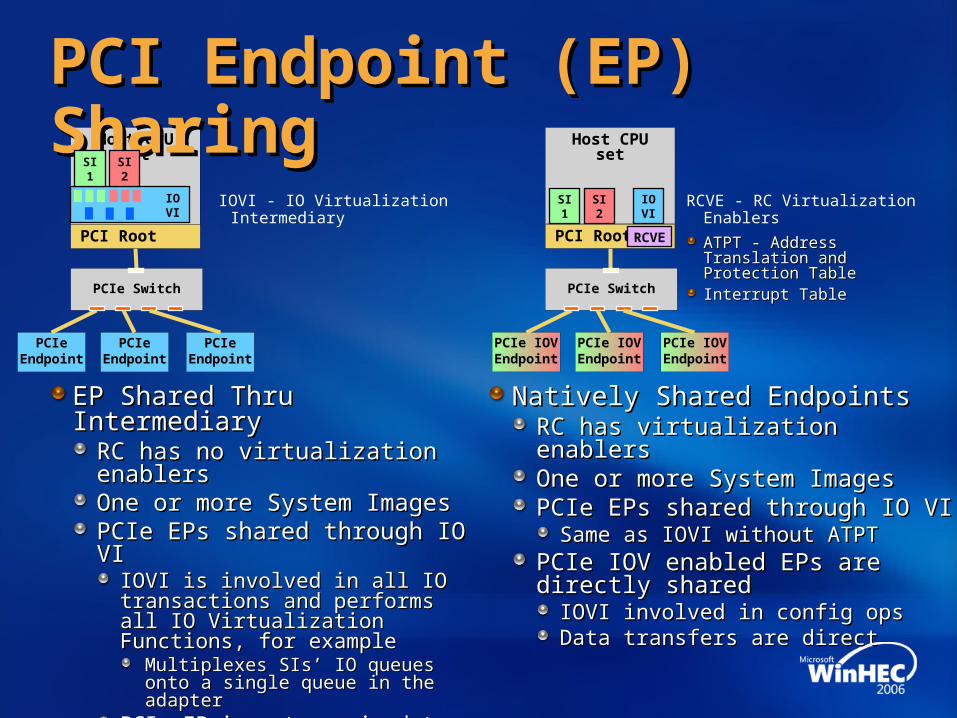
PCI Endpoint (EP) SharingPCI Endpoint (EP) Sharing
EP Shared Thru IntermediaryEP Shared Thru IntermediaryRC has no virtualization enablersRC has no virtualization enablersOne or more System ImagesOne or more System ImagesPCIe EPs shared through IO VIPCIe EPs shared through IO VI
IOVI is involved in all IO transactions IOVI is involved in all IO transactions and performs all IO Virtualization and performs all IO Virtualization Functions, for exampleFunctions, for example
Multiplexes SIs’ IO queuesMultiplexes SIs’ IO queuesonto a single queue in the adapteronto a single queue in the adapter
PCIe EP is not required to support PCIe EP is not required to support any virtualization functionsany virtualization functions
Natively Shared EndpointsNatively Shared EndpointsRC has virtualization enablersRC has virtualization enablersOne or more System ImagesOne or more System ImagesPCIe EPs shared through IO VIPCIe EPs shared through IO VI
Same as IOVI without ATPTSame as IOVI without ATPTPCIe IOV enabled EPs are PCIe IOV enabled EPs are directly shareddirectly shared
IOVI involved in config opsIOVI involved in config opsData transfers are directData transfers are direct
PCI Root
PCIeEndpoint
SI1
SI2
PCIe Switch
PCIeEndpoint
PCIeEndpoint
Host CPU set
PCI Root
PCIe IOVEndpoint
SI1
SI2
PCIe Switch
IOVI
PCIe IOVEndpoint
PCIe IOVEndpoint
RCVE
RCVE - RC Virtualization Enablers
ATPT - Address Translation and ATPT - Address Translation and Protection TableProtection TableInterrupt TableInterrupt Table
IOVI - IO Virtualization Intermediary

TerminologyTerminology
Configuration Time VI Involvement – refers to the Configuration Time VI Involvement – refers to the operations performed by the VI to configure a Virtual operations performed by the VI to configure a Virtual Function and associate it with an SIFunction and associate it with an SIRun-Time VI Involvement – refers to the intervention by a Run-Time VI Involvement – refers to the intervention by a VI on data movement and interrupt operations performed VI on data movement and interrupt operations performed between an SI and a physical PCI Function between an SI and a physical PCI Function (versus a Virtual Function)(versus a Virtual Function)Native based PCI IOV – an IOV mechanism whereNative based PCI IOV – an IOV mechanism where
A physical PCI Endpoint supports A physical PCI Endpoint supports one or more Virtual Functionsone or more Virtual FunctionsEach IOV enabled Endpoint is associated with an SIEach IOV enabled Endpoint is associated with an SIEach IOV enabled Endpoint is created through Each IOV enabled Endpoint is created through IOVI issued configuration operationsIOVI issued configuration operationsThe Virtual System may support mechanisms that allow The Virtual System may support mechanisms that allow data movement and interrupt operations to be performed data movement and interrupt operations to be performed directly between an SI and the IOV enabled directly between an SI and the IOV enabled Endpoint, without VI involvementEndpoint, without VI involvement

Adapter IOV Mechanisms Adapter IOV Mechanisms Within A Single Physical SystemWithin A Single Physical System
Dedicated Adapter(No Virtualization)
Adapter Shared Through Intermediary
Natively Shared Adapter
Graphic Depiction
Intermediary Role None
Virtualizes physical I/O by intervening on configuration and data transfer operations
Manages assignment of Virtual Resources by intervening on
configuration operations
Configuration Operation Path
SI direct to AdapterVI serves as proxy
(SI to VI; VI to Adapter)VI serves as proxy
(SI to VI; VI to Adapter)
Data Transfer Operation Path
SI direct to AdapterVI serves as proxy
(SI to VI; VI to Adapter)SI direct to Adapter
Physical System
SystemImage 1
Physical I/O
SystemImage 2
I/O VirtualizationIntermediary
Physical System
SystemImage 1
Physical I/O
SystemImage 2
I/O VirtualizationIntermediary
Physical System
SystemImage 1
Physical I/O

PCI Root ComplexPCI Root ComplexVirtualization EnablersVirtualization Enablers
Address Translation and Protection TableAddress Translation and Protection TableTranslates and protects system memory accessed thru PCI busTranslates and protects system memory accessed thru PCI bus
Consists of the following functionsConsists of the following functionsOn incoming DMA from a PCI adapter, translates the On incoming DMA from a PCI adapter, translates the PCI Bus Address into an address that can be used PCI Bus Address into an address that can be used to directly access host memoryto directly access host memory
Provides Physical Adapter Isolation by assuring that Provides Physical Adapter Isolation by assuring that when a PCIe function performs a DMA, operation when a PCIe function performs a DMA, operation targets an SI associated with that functiontargets an SI associated with that function
Interrupt TableInterrupt TableRoutes PCI interrupts to the System Image associated with the Routes PCI interrupts to the System Image associated with the PCI BDF# that generated the interruptPCI BDF# that generated the interrupt
Note: PCI-SIG is not standardizing aboveNote: PCI-SIG is not standardizing above

IOVISI
ATPT Based DMAATPT Based DMA
DMA Services performed by IOVIDMA Services performed by IOVIInitializationInitialization
Pins host memoryPins host memoryAssigns DMA AddressesAssigns DMA AddressesProgram the ATPT entriesProgram the ATPT entriesReturn a PCI memory address to DD*Return a PCI memory address to DD*
CompletionCompletionInvalidates ATPT EntriesInvalidates ATPT EntriesUnpins host memoryUnpins host memoryReleases DMA AddressesReleases DMA Addresses
Address Translation and Address Translation and Protection performed at or Protection performed at or above the RCabove the RC
Validates incoming PCI memory Validates incoming PCI memory accesses, for example by limiting accesses, for example by limiting the memory addresses accessible the memory addresses accessible by a PCIe BDF#by a PCIe BDF#Converts incoming PCI memory Converts incoming PCI memory address to the associated RC address to the associated RC system bus memory addresssystem bus memory address
User
App/libraryFile
SystemDevice
DriverDriver
Services
RC ATPT
(Validate PCIDMA and then
translate)
PCIDMA
read/write
request
System
DMA
read/write
request
PCI Bus System BusRoot Complex
SW Model HW Model
*Note: Some IOVI implementations may not supply address back to SI*Note: Some IOVI implementations may not supply address back to SI
FCSwitch
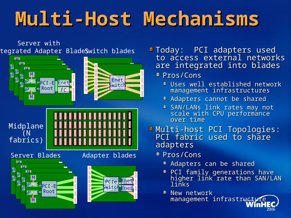
Multi-Host MechanismsMulti-Host Mechanisms
Today: PCI adapters used to Today: PCI adapters used to access external networks are access external networks are integrated into bladesintegrated into blades
Pros/ConsPros/ConsUses well established network Uses well established network management infrastructuresmanagement infrastructuresAdapters cannot be sharedAdapters cannot be sharedSAN/LANs link rates may not scale with SAN/LANs link rates may not scale with CPU performance over timeCPU performance over time
Multi-host PCI Topologies: PCI Multi-host PCI Topologies: PCI fabric used to share adaptersfabric used to share adapters
Pros/ConsPros/ConsAdapters can be sharedAdapters can be sharedPCI family generations have higher link PCI family generations have higher link rate than SAN/LAN linksrate than SAN/LAN linksNew network New network management infrastructuremanagement infrastructure
Midplane (N fabrics)
Switch bladesServer with
Integrated Adapter Blades
Adapter bladesServer Blades
EnetSwitch
Enet
FC
M
uP, $
MuP, $ PCI-E
Root Enet
FC
M
uP, $
MuP, $ PCI-E
Root Enet
FC
M
uP, $
MuP, $ PCI-E
Root Enet
FC
M
uP, $
MuP, $ PCI-E
Root
PCIeSwitch
Enet
EnetM
uP, $
M
uP, $ PCI-ERoot
M
uP, $
M
uP, $ PCI-ERoot
M
uP, $
M
uP, $ PCI-ERoot
M
uP, $
M
uP, $ PCI-ERoot

Scope Of WorkScope Of WorkOverviewOverview
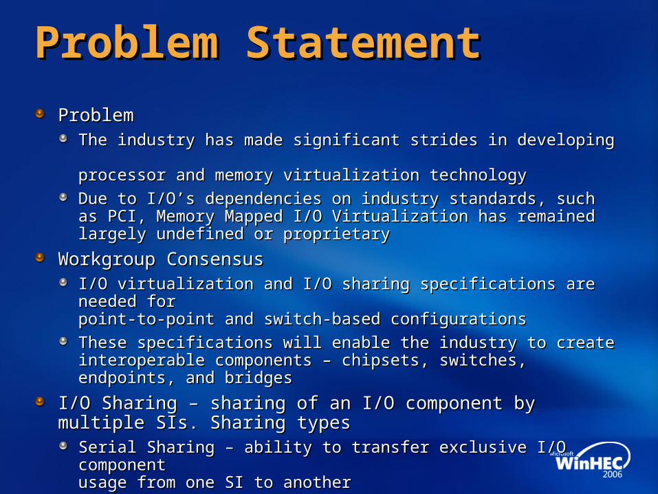
Problem StatementProblem Statement
ProblemProblemThe industry has made significant strides in developing The industry has made significant strides in developing processor and memory virtualization technologyprocessor and memory virtualization technology
Due to I/O’s dependencies on industry standards, such Due to I/O’s dependencies on industry standards, such as PCI, Memory Mapped I/O Virtualization has remained as PCI, Memory Mapped I/O Virtualization has remained largely undefined or proprietarylargely undefined or proprietary
Workgroup ConsensusWorkgroup ConsensusI/O virtualization and I/O sharing specifications are needed forI/O virtualization and I/O sharing specifications are needed forpoint-to-point and switch-based configurationspoint-to-point and switch-based configurations
These specifications will enable the industry to create interoperable These specifications will enable the industry to create interoperable components – chipsets, switches, endpoints, and bridgescomponents – chipsets, switches, endpoints, and bridges
I/O Sharing – sharing of an I/O component by I/O Sharing – sharing of an I/O component by multiple SIs. Sharing typesmultiple SIs. Sharing types
Serial Sharing – ability to transfer exclusive I/O component Serial Sharing – ability to transfer exclusive I/O component usage from one SI to another usage from one SI to another
Simultaneous Sharing – ability to share an I/O Simultaneous Sharing – ability to share an I/O component by multiple SIs in parallelcomponent by multiple SIs in parallel

High-Level RequirementsHigh-Level Requirements
The scope will be limited to the The scope will be limited to the PCIe specification suitePCIe specification suite
No materials generated will require No materials generated will require changes to conventional PCI or changes to conventional PCI or PCI-X specification suitesPCI-X specification suites
The scope may include changes to the The scope may include changes to the PCI Firmware Spec based on subsequent PCI Firmware Spec based on subsequent investigation by the workgroupinvestigation by the workgroup

High-Level RequirementsHigh-Level Requirements
The scope will enable an I/O The scope will enable an I/O Endpoint to be serially shared or Endpoint to be serially shared or simultaneously shared by simultaneously shared by multiple SIs (e.g. OS guests)multiple SIs (e.g. OS guests)in a single hierarchy in a single hierarchy domain (single RC)domain (single RC)
Single Root (SR) IOV Enabled Single Root (SR) IOV Enabled Endpoint – an Endpoint that Endpoint – an Endpoint that supports the required IOV supports the required IOV extensions defined in extensions defined in this specificationthis specification
The scope will investigate The scope will investigate whether new mechanisms are whether new mechanisms are required to prevent, or required to prevent, or selectively prevent, peer-to-peer selectively prevent, peer-to-peer operations within a operations within a single RC hierarchysingle RC hierarchy
PCIe Switch
Host CPU set
PCI Root
PCIeEndpoint
PCIe Switch
PCIeEndpoint
PCIe Endpoint
SI
1
SI
2
PCI-XAdapter
PCI-X Bridge
PCIM
PCI-XAdapter
PCI-XAdapter
PCIAdapter
PCI Bridge
PCI-XAdapter
PCI-XAdapter

High-Level RequirementsHigh-Level Requirements
The scope will enable an I/O The scope will enable an I/O Endpoint to be serially shared or Endpoint to be serially shared or simultaneously shared by simultaneously shared by multiple SIs (e.g. OS guests)multiple SIs (e.g. OS guests)in a single hierarchy domain in a single hierarchy domain (single RC) or in a multi-(single RC) or in a multi-hierarchy domain (multiple RC hierarchy domain (multiple RC connected to a common connected to a common PCIe switch fabric)PCIe switch fabric)
Multi-Root (MR) IOV Enabled Multi-Root (MR) IOV Enabled Endpoint – an Endpoint that Endpoint – an Endpoint that supports the required IOV multi-supports the required IOV multi-root extensions defined root extensions defined in this specificationin this specification
PCIe Switch
Host CPU set
PCI Root
PCIeEndpoint
PCIe Switch
PCIeEndpoint
PCIe Endpoint
SI
1
SI
2
PCI-XAdapter
PCI-X Bridge
PCIAdapter
PCI Bridge
PCIM
PCI-XAdapter
PCI-XAdapter
PCI-XAdapter
PCI-XAdapter
PCIe Switch
Host CPU set
PCI Root
SI
3
OptionalOptionalSMPSMP
FabricFabric
PCIe Endpoint

High-Level RequirementsHigh-Level Requirements
Attachment of existing PCIe 1.x Base Attachment of existing PCIe 1.x Base components – RC, Switches, components – RC, Switches, Endpoints and BridgesEndpoints and BridgesA solution to use a combination of existing A solution to use a combination of existing base and IOV-aware componentsbase and IOV-aware components
Single-RC capabilities shall be Single-RC capabilities shall be a superset of the PCIe 1.x Base specificationa superset of the PCIe 1.x Base specificationMulti-RC capabilities shall be Multi-RC capabilities shall be a superset of the single-RC capabilities a superset of the single-RC capabilities Objective is to maximize component Objective is to maximize component interoperability across multiple topologies, e.g.interoperability across multiple topologies, e.g.
An I/O component designed to support multi-RC An I/O component designed to support multi-RC shall support the single-RC capabilitiesshall support the single-RC capabilities
IOV-capable components to be backwards IOV-capable components to be backwards compatible with existing softwarecompatible with existing software
Although some or all of the new IOV capabilities Although some or all of the new IOV capabilities may not be supported in these circumstancesmay not be supported in these circumstances
Base
Single-RC
Multi-RC
The scope will enable:

High-Level RequirementsHigh-Level Requirements
Virtual Function (VF) - a Function, within an IOV enabled Endpoint, Virtual Function (VF) - a Function, within an IOV enabled Endpoint, that shares one or more physical Endpoint resources, such as a link, that shares one or more physical Endpoint resources, such as a link, with another and can, without run-time intervention by a VI, directlywith another and can, without run-time intervention by a VI, directly
Sink I/O and Memory operations from an SI; andSink I/O and Memory operations from an SI; andSource DMA, completion and interrupt operations to an SI Source DMA, completion and interrupt operations to an SI
An IOVI is still required for configuration operationsAn IOVI is still required for configuration operations
The scope will include support for the allocation, management, and de-The scope will include support for the allocation, management, and de-allocation of resources associated with an IOV enabled Endpointallocation of resources associated with an IOV enabled Endpoint
An IOV enabled Endpoint may be serially or simultaneously shared by one An IOV enabled Endpoint may be serially or simultaneously shared by one or more RC or SIsor more RC or SIs
PCIe IOVEndpoint
ConfigurationManagement
VF(Virtual Function1)
VF(Virtual Function2)
VF(Virtual FunctionN)
:Physical ResourcesN
Physical Resources2
Physical Resources1
Internal Routing
Non-separable Resources
PCIe Port
Sharable Resource Pool

High-Level RequirementsHigh-Level Requirements
Address Translation Services (ATS) – the caching of Address Translation Services (ATS) – the caching of information used within an ATC (Address Translation Cache) information used within an ATC (Address Translation Cache) by the EP to translate a PCI bus address in order by the EP to translate a PCI bus address in order to access host memoryto access host memory
The scope will include support for an Endpoint to request The scope will include support for an Endpoint to request translated addresses prior to injecting a request to a RC,translated addresses prior to injecting a request to a RC,e.g. a DMA Read or DMA Write operatione.g. a DMA Read or DMA Write operation
The minimum expected operations areThe minimum expected operations are Request a translation,Request a translation,
Return a translated address, and Return a translated address, and
Invalidate a prior translation Invalidate a prior translation
PCIe IOVEndpoint
ConfigurationManagement
VF(Virtual Function1)
VF(Virtual Function2)
VF(Virtual FunctionN)
:Physical ResourcesN
Physical Resources2
Physical Resources1
Internal Routing
Non-separable Resources
PCIe Port
Sharable Resource Pool
ATC1
ATC2
ATC3

GoalsGoals
The scope of this work will enableThe scope of this work will enable
The development of interoperable components – The development of interoperable components – RC, switches, endpoints, and bridges – RC, switches, endpoints, and bridges – that provide I/O virtualization and sharing capabilities that provide I/O virtualization and sharing capabilities
These components may be jointly deployed with existing PCIe 1.x These components may be jointly deployed with existing PCIe 1.x based components to provide varying degrees of functionality based components to provide varying degrees of functionality
Multiple SIs toMultiple SIs toBe co-located onto a shared physical domain; andBe co-located onto a shared physical domain; and
Provide attestable trust and fault isolation, when co-locatedProvide attestable trust and fault isolation, when co-located
Support for a variety of physical topologiesSupport for a variety of physical topologiesenabling the technology to be deployed across enabling the technology to be deployed across multiple market segments and usage modelsmultiple market segments and usage models
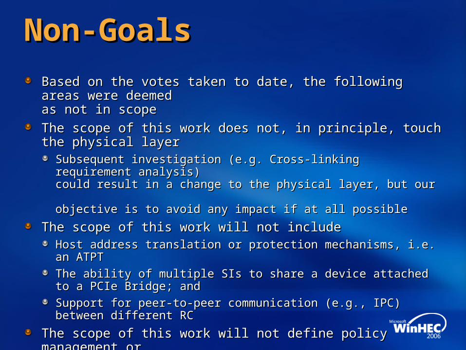
Non-GoalsNon-Goals
Based on the votes taken to date, the following areas were deemed Based on the votes taken to date, the following areas were deemed as not in scopeas not in scope
The scope of this work does not, in principle, touch the physical layerThe scope of this work does not, in principle, touch the physical layerSubsequent investigation (e.g. Cross-linking requirement analysis)Subsequent investigation (e.g. Cross-linking requirement analysis)could result in a change to the physical layer, but our could result in a change to the physical layer, but our objective is to avoid any impact if at all possibleobjective is to avoid any impact if at all possible
The scope of this work will not includeThe scope of this work will not includeHost address translation or protection mechanisms, i.e. an ATPTHost address translation or protection mechanisms, i.e. an ATPT
The ability of multiple SIs to share a device attached to a PCIe Bridge; andThe ability of multiple SIs to share a device attached to a PCIe Bridge; and
Support for peer-to-peer communication (e.g., IPC) between different RCSupport for peer-to-peer communication (e.g., IPC) between different RC
The scope of this work will not define policy management or The scope of this work will not define policy management or other types of management functions used to provide higher-level other types of management functions used to provide higher-level management of the components specified by this workgroup. That ismanagement of the components specified by this workgroup. That is
The scope will be conceptually focused on PCIe operation types,The scope will be conceptually focused on PCIe operation types,such as: Configuration operations, event notification operations, etc.such as: Configuration operations, event notification operations, etc.

Scope Of WorkScope Of WorkSingle Root RequirementsSingle Root Requirements

Single RC PCIe IOV Single RC PCIe IOV Enabled Endpoint RequirementsEnabled Endpoint Requirements
Only PCIe endpointsOnly PCIe endpointsshall be specified for shall be specified for IOV enabled Endpoints IOV enabled Endpoints
Native based PCI SR OV Native based PCI SR OV enabled Endpoints shall be enabled Endpoints shall be backwards compatible, in a backwards compatible, in a non virtualized mode, with non virtualized mode, with PCIe base 1.x SPECPCIe base 1.x SPEC
PCIe Switch
Host CPU set
PCI Root
PCIe IOVEndpoint
PCIe IOVEndpoint
PCIe Endpoint
PCIe Switch
SI
1
SI
N
PCI-XAdapter
PCI-X Bridge
PCIM
PCIAdapter
PCI Bridge
PCI-XAdapter
PCIAdapter
PCIe Switch
Host CPU set
PCI Root
PCIe IOVEndpoint
PCIe IOVEndpoint
PCIe Endpoint
PCIe Switch
SI
Base PCIe 1.x System
IOV Enabled PCIe System

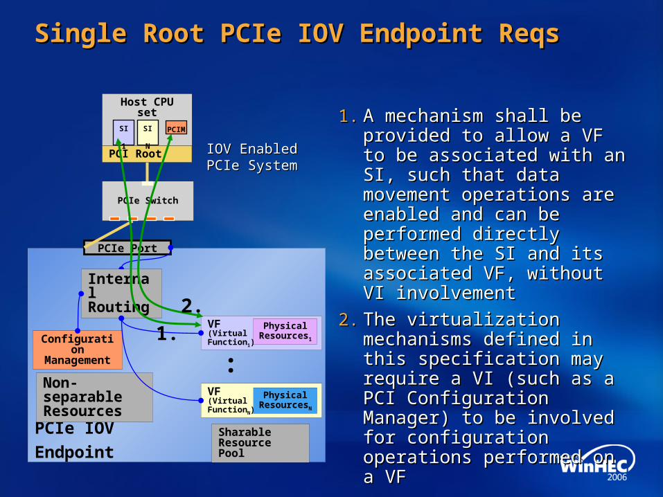
Single Root PCIe IOV Endpoint ReqsSingle Root PCIe IOV Endpoint Reqs
Each VF shall have the capability Each VF shall have the capability to independentlyto independently1.1. Source DMA, completion, and Source DMA, completion, and
interrupt operations within the system interrupt operations within the system as an initiator;as an initiator;
2.2. Sink configuration, I/O, and Sink configuration, I/O, and memory operations within memory operations within the system as a targetthe system as a target
Each VF shall appear in the fabric Each VF shall appear in the fabric as a PCIe functionas a PCIe functionExcept for rare errors conditions Except for rare errors conditions (spec will provide examples)(spec will provide examples)
Each transaction issued from the Each transaction issued from the PCIe IOV enabled Endpoint shall be PCIe IOV enabled Endpoint shall be uniquely identifiable with the VF that uniquely identifiable with the VF that sourced the transactionsourced the transactionThe PCIe IOV enabled Endpoint shall The PCIe IOV enabled Endpoint shall be able to associate each transaction be able to associate each transaction it sinks with the appropriate VFit sinks with the appropriate VF
PCIe IOV
Endpoint
ConfigurationManagement
VF(Virtual Function1)
VF(Virtual Function2)
VF(Virtual FunctionN)
:Physical
ResourcesN
Physical Resources2
Physical Resources1
Internal Routing
Non-separable Resources
PCIe Port
Sharable Resource Pool
1.
2.
1.
2.1.
2.

Single Root PCIe IOV Endpoint ReqsSingle Root PCIe IOV Endpoint Reqs
IOV enabled Endpoints shallIOV enabled Endpoints shall1.1. Support a standard, in-band, mechanism for Support a standard, in-band, mechanism for
managing the IOV endpoint; managing the IOV endpoint; 2.2. Include functionality to disable their peer to Include functionality to disable their peer to
peer traffic to other functions within the IOV peer traffic to other functions within the IOV Endpoint Endpoint
3.3. Be allowed to support multiple functions Be allowed to support multiple functions assigned to the same SI with the same level of assigned to the same SI with the same level of functionality given to a current functionality given to a current multi-function devicemulti-function device
4.4. Support defined arbitration mechanisms Support defined arbitration mechanisms between the VF’s within an IOV between the VF’s within an IOV enabled endpointenabled endpoint
5.5. Support the capability to have each VF Support the capability to have each VF independently managed, includingindependently managed, including
Functional reset (i.e. full Functional reset (i.e. full device function state), device function state), Enable/Disable (a.k.a. Create/Destroy)Enable/Disable (a.k.a. Create/Destroy)Having a VF’s PCIe state and Having a VF’s PCIe state and resources modified, for exampleresources modified, for example
TC assignment, TC assignment, Bus Master Enable, Bus Master Enable,
Support the specification of the minimum and Support the specification of the minimum and maximum number of resources maximum number of resources available to each VFavailable to each VF
PCIe IOV
Endpoint
ConfigurationManagement
VF(Virtual Function1)
VF(Virtual Function2)
VF(Virtual FunctionN)
:
Internal Routing
Non-separable Resources
PCIe Port
Sharable Resource Pool
1.
2.
3.
4.
Physical Resources2
Physical Resources1
Physical ResourcesN
5.
Single Root PCIe IOV Endpoint ReqsSingle Root PCIe IOV Endpoint Reqs
1.1. A mechanism shall be provided A mechanism shall be provided to allow a VF to be associated to allow a VF to be associated with an SI, such that data with an SI, such that data movement operations are movement operations are enabled and can be performed enabled and can be performed directly between the SI and its directly between the SI and its associated VF, without associated VF, without VI involvementVI involvement
2.2. The virtualization mechanisms The virtualization mechanisms defined in this specification may defined in this specification may require a VI (such as a PCI require a VI (such as a PCI Configuration Manager) to be Configuration Manager) to be involved for configuration involved for configuration operations performed on a VFoperations performed on a VF
PCIe IOV
Endpoint
ConfigurationManagement
VF(Virtual Function1)
VF(Virtual FunctionN)
:
Internal Routing
Non-separable Resources
Sharable Resource Pool
PCIe Port
PCIe Switch
Host CPU set
PCI Root
SI
1
SI
N
PCIM
IOV Enabled IOV Enabled PCIe SystemPCIe System
1.
2.
Physical ResourcesN
Physical Resources1
Scope Of WorkScope Of WorkMulti-Root RequirementsMulti-Root Requirements
Multi-Root PCIe IOV Endpoint RequirementsMulti-Root PCIe IOV Endpoint Requirements
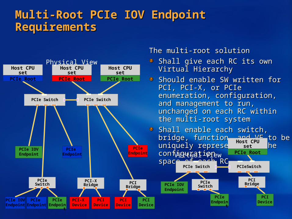
The multi-root solutionThe multi-root solution
Shall give each RC its own Shall give each RC its own Virtual HierarchyVirtual Hierarchy
Should enable SW written for PCI, PCI-X, Should enable SW written for PCI, PCI-X, or PCIe enumeration, configuration, and or PCIe enumeration, configuration, and management to run, unchanged on each management to run, unchanged on each RC within the multi-root systemRC within the multi-root system
Shall enable each switch, bridge, Shall enable each switch, bridge, function, and VF to be uniquely function, and VF to be uniquely represented in the configuration represented in the configuration space of each RCspace of each RC
Host CPU set
PCIe Root
Host CPU set
PCIe Root
Host CPU set
PCIe Root
PCI-X Device
PCI-X Bridge
PCIDevice
PCIDevice
PCI Bridge
PCIe IOVEndpoint
PCIDevice
PCIe IOVEndpoint
PCIe Switch
PCIeEndpoint
PCIe Endpoint
PCIe Endpoint
PCIeEndpoint
PCIe Switch PCIe Switch
Host CPU set
PCIe Root
PCI BridgePCIe IOVEndpoint
PCIDevice
PCIe Switch
PCIeEndpoint
PCIe Switch PCIeSwitch
Virtual View
Physical View

Multi-Root PCIe IOV Endpoint RequirementsMulti-Root PCIe IOV Endpoint Requirements
The multi-root solution shallThe multi-root solution shall1.1. Provide the same characteristics to Provide the same characteristics to
its IOV enabled Endpoints as the its IOV enabled Endpoints as the single-root solution relative to single-root solution relative to separate SIsseparate SIs
2.2. Enable use of existing PCIe Enable use of existing PCIe 1.x or later RC1.x or later RC
3.3. Enable existing PCIe 1.x Switches, Enable existing PCIe 1.x Switches, Endpoints, and PCIe to PCI/PCI-X Endpoints, and PCIe to PCI/PCI-X Bridges to each be bound to a Bridges to each be bound to a single RCsingle RC
4.4. Enable an IOV enabled endpoint to Enable an IOV enabled endpoint to be shared amongst multiple RC’s be shared amongst multiple RC’s using a Multi-Root Aware (MRA) using a Multi-Root Aware (MRA) PCIe switchPCIe switch
MRA PCIe Switch
Host CPU set
MRA PCIe Root
PCIeEndpoint
MRA PCIe Switch
PCIeEndpoint
PCIe Endpoint
SI
1
SI
2
PCI-XAdapter
MRA PCI-X Bridge
PCIAdapter
PCI Bridge
PCI-XAdapter
PCI-XAdapter
PCI-XAdapter
PCI-XAdapter
MRA PCIe Switch
Host CPU set
PCIe 1.x Root
SI
3
OptionalSMP
Fabric SI
3
2.
1. 1.
3.
3.4.
4.
PCIM

Multi-Root PCIe IOV Endpoint RequirementsMulti-Root PCIe IOV Endpoint Requirements
The multi-root solution shallThe multi-root solution shall5.5. Enable a PCIe 1.x MRA Enable a PCIe 1.x MRA
bridge to PCI/PCI-X to assign bridge to PCI/PCI-X to assign each of its independent each of its independent busses to a separate RCbusses to a separate RC
6.6. Enable multiple MRA Enable multiple MRA switches to be connected switches to be connected together together
7.7. Enable an IOV enabled Enable an IOV enabled Endpoint to be shared by Endpoint to be shared by multiple SIs within multiple SIs within one or more RC’sone or more RC’s
8.8. Enable hot-plug of physical Enable hot-plug of physical EPs and VFsEPs and VFs
9.9. Enable a management entityEnable a management entity(PCI Configuration Manger, (PCI Configuration Manger, PCIM) to manage the fabricPCIM) to manage the fabric
MRA PCIe Switch
Host CPU set
MRA PCIe Root
PCIeEndpoint
MRA PCIe Switch
PCIeEndpoint
PCIe Endpoint
SI
1
SI
2
PCI-XAdapter
MRA PCI-X Bridge
PCIAdapter
PCI Bridge
PCI-XAdapter
PCI-XAdapter
PCI-XAdapter
PCI-XAdapter
MRA PCIe Switch
Host CPU set
PCIe 1.x Root
SI
3
OptionalSMP
Fabric
PCIe Endpoint
SI
3
6.
5.
7. 7.
7.
8.
9.PCIM

LegendLegend VE N_M = Virtual EP in Physical EP N and associated with Image MVE N_M = Virtual EP in Physical EP N and associated with Image M
For Adapter – fill Color shows SI association; Line Color shows root complex associationFor Adapter – fill Color shows SI association; Line Color shows root complex association
VP = Virtual Plane as defined by a new VP field which is associated with an RCVP = Virtual Plane as defined by a new VP field which is associated with an RC
Host CPU set
PCIe MRA Root
PCIe MRA Switch
PCIe MRA Switch
SI1
SI2
Host CPU set
PCIe Root
SI3
Host CPU set
PCIe Root
SI4
SI5
VE1_1
VE2_3
VE2_4
VE2_5
PCI Bridge or Switch
EP 3_2 EP 4_5VE1_2
VP Table
VP Table
PCIM
VP Domain
Virtual Plane Based MRVirtual Plane Based MRShowing mix of legacy and MRA ComponentsShowing mix of legacy and MRA Components

Virtual Plane Based MRVirtual Plane Based MRVirtual Plane Based MRVirtual Plane Based MR
Note Each VP has its own upstream and downstream memory addresses (more on the next pages)Each legacy RC is assigned its own VPIf in-band management is used, then VP is dedicated for PCIM on an MRA RC Otherwise out-of-band management can be used
Host CPU set
PCIe MRA Root
PCIe MRA Switch
PCIe MRA Switch
SI1
SI2
Host CPU set
PCIe Root
SI3
Host CPU set
PCIe Root
SI4
SI5
VE1_1
VE2_3
VE2_4
VE2_5
PCI Bridge or Switch
EP 3_2 EP 4_5VE1_2
VP1 VP2 VP3
VP1VP2VP3
VP0
VP1VP2VP3
VP0
VP1VP2VP3
VP0VP0
VP0
VP Table
VP Table
PCIM
VP1VP0
VP Domain

Opt.Opt.BDFBDF
##
AddreAddress ss
rangerange
PorPort #t #
VP VP ##
Opt.Opt.BDFBDF
##
AddreAddress ss
rangerange
PorPort #t #
VP VP ##
Multi-Root Aware Switch And EP SupportMulti-Root Aware Switch And EP SupportMulti-Root Aware Switch And EP SupportMulti-Root Aware Switch And EP Support
PCIe MRA Switch
Legend VP = Virtual Plane as defined by a new VP field which is associated with an RC
Translate
VP#
VP#VP#
PCIM sets up VP Tables in MRA Switches PCIM sets up VP Tables in MRA Switches at the time the VE get assigned to RCsat the time the VE get assigned to RCs
For MRA switches the VP table is used to For MRA switches the VP table is used to determine outbound portdetermine outbound port
Current PCI IOV WG direction is that the Current PCI IOV WG direction is that the VP# is at DLLP (i.e. not part of TLP)VP# is at DLLP (i.e. not part of TLP)
VP#VP# BDF# and Addr.BDF# and Addr.
PCIe Packet
VP1VP2VP3
VP0
Downstream (e.g. MMIO)Upstream (e.g. DMA)
VP#VP# BDF# and Addr.BDF# and Addr.
PCIe Packet
VP#VP# BDF# and Addr.BDF# and Addr.
PCIe Packet
VP#VP# BDF# and Addr.BDF# and Addr.
PCIe Packet
Opt.Opt.BDFBDF
##
AddreAddress ss
rangerange
PorPort #t #
VP VP ##
Opt.Opt.BDF#BDF#
RC Addr. RC Addr. rangerange
Port Port ##
VP VP ##
Opt.Opt.BDFBDF
##
AddreAddress ss
rangerange
PorPort #t #
VP VP ##
Opt.Opt.BDFBDF
##
AddreAddress ss
rangerange
PorPort #t #
VP VP ##
Opt.Opt.BDFBDF
##
AddreAddress ss
rangerange
PorPort #t #
VP VP ##
Opt.Opt.BDF#BDF#
EP Addr. EP Addr. rangerange
Port Port ##
VP VP ##
VE1_1
VE2_3
VE2_4
VE2_5
VE1_2
VP1VP2VP3
VP Domain

Legacy Switch And EP SupportLegacy Switch And EP SupportLegacy Switch And EP SupportLegacy Switch And EP Support
PCIe MRA Switch
Legend VP = Virtual (address) Plane as defined by a new VP field which is associated with each BDF#
Single VPTranslate
VP#
BDF#
PCI Bridge or Switch
AdapterAdapter
Upstream (e.g. DMA)
PCIM sets up VP Tables in MRA Switches at PCIM sets up VP Tables in MRA Switches at the time the VEP get assigned to RCsthe time the VEP get assigned to RCs
Non-MRA components (e.g. I/O bridges, Non-MRA components (e.g. I/O bridges, switches, and adapters that do not MR), are switches, and adapters that do not MR), are assigned to one and only one VP#assigned to one and only one VP#
PCIe MRA Switch performs translation when PCIe MRA Switch performs translation when entering MRA domainentering MRA domain
Inserts VP# associated with componentInserts VP# associated with component
VP#VP# PBA 1 AddressPBA 1 Address
PCIe Packet
BDF#BDF# PBA 1 AddressPBA 1 Address
PCIe PacketBDF#BDF# PBA 1 AddressPBA 1 Address
PCIe Packet
VP#VP# PBA 1 AddressPBA 1 Address
PCIe PacketDownstream (e.g. MMIO)
Opt.Opt.BDF#BDF#
RC Addr. RC Addr. rangerange
PortPort ##
VP VP ##
Opt.Opt.BDF#BDF#
EP Addr. EP Addr. rangerange
PortPort ##

PCIM RequirementsPCIM RequirementsThe PCIM shall be able toThe PCIM shall be able to
Discover and configure IOV enabled RC’s, Discover and configure IOV enabled RC’s, switches, bridges, and endpoints using a switches, bridges, and endpoints using a defined PCIM interfacedefined PCIM interface
Discover and configure non-IOV Discover and configure non-IOV components using existing interfacescomponents using existing interfaces
Control and manage errors within the fabricControl and manage errors within the fabric
The solution supports one or more PCIM The solution supports one or more PCIM entities (with coordination between them)entities (with coordination between them)
A method will be definedA method will be definedTo establish a trust relationship between a To establish a trust relationship between a PCIM and a given PCIe componentPCIM and a given PCIe component
For the PCIM to control and limit access to For the PCIM to control and limit access to IOV management functions within IOV management functions within PCIe IOV enabled Endpoints PCIe IOV enabled Endpoints by entities other than the primary PCIMby entities other than the primary PCIM
The PCI Express Multi-Root The PCI Express Multi-Root Configuration provides multiple Configuration provides multiple configuration spaces for each switch, configuration spaces for each switch, bridge and endpointbridge and endpoint
MRA PCIe Switch
Host CPU set
MRA PCIe Root
PCIeEndpoint
MRA PCIe Switch
PCIeEndpoint
PCIe Endpoint
SI
1
SI
2
PCI-XAdapter
MRA PCI-X Bridge
PCIAdapter
PCI Bridge
PCI-XAdapter
PCI-XAdapter
PCI-XAdapter
PCI-XAdapter
MRA PCIe Switch
Host CPU set
PCIe 1.x Root
SI
3
OptionalSMP
Fabric
PCIe Endpoint
SI
3
PCIM PCIM

Scope Of WorkScope Of WorkAddress Translation Address Translation Services RequirementsServices Requirements

ATS RequirementsATS Requirements
Address Translation Services (ATS) will consist of Address Translation Services (ATS) will consist of a set of transactions to enable an Endpoint toa set of transactions to enable an Endpoint to
Request a translation of a given addressRequest a translation of a given address
Indicate that a subsequent transaction, Indicate that a subsequent transaction, e.g. a DMA Read or DMA Write, has been translated.e.g. a DMA Read or DMA Write, has been translated.
Invalidation response to indicate that a translation Invalidation response to indicate that a translation invalidation request has been processed invalidation request has been processed
ATS will consist of a set of transactions to enable ATS will consist of a set of transactions to enable a host Address Translation and Protection Table a host Address Translation and Protection Table (ATPT) via an RC to(ATPT) via an RC to
Issue a translation completion of a given addressIssue a translation completion of a given address
Issue a translation invalidation request for a given addressIssue a translation invalidation request for a given address
Ascertain whether an invalidation has been Ascertain whether an invalidation has been processed by an Endpointprocessed by an Endpoint

ATS RequestATS Request
ATS Request ATS Request Used by the Endpoint to request Used by the Endpoint to request translated addresstranslated address
Address can be 32-bit or 64-bitAddress can be 32-bit or 64-bit
Requests can flow on any TCRequests can flow on any TCMultiple ATS Requests may Multiple ATS Requests may be pipelined be pipelined
PCIe Endpoint ResponsibilitiesPCIe Endpoint ResponsibilitiesEndpoint implements an ATCEndpoint implements an ATC
ATC is a cache of translated addressesATC is a cache of translated addressesATC may be implemented independent ATC may be implemented independent of IOV supportof IOV support
Endpoint must only populate cache Endpoint must only populate cache via ATS protocolvia ATS protocolEndpoint must not allow ATC to be Endpoint must not allow ATC to be modified or accessed by software modified or accessed by software (local or remote) to prevent (local or remote) to prevent data leakagedata leakageFor each ATS Request, there will be For each ATS Request, there will be a corresponding ATS Completion a corresponding ATS Completion
SystemDMA
Read / writerequest
System Bus
PCIe IOV
Endpoint
ConfigurationManagement
VF(Virtual Function1)
VF(Virtual Function2)
VF(Virtual FunctionN)
:
Physical ResourcesN
Physical Resources2
Physical Resources1
Internal Routing
Non-separable Resources
PCIe Port
Sharable Resource Pool
ATC1
ATC2
ATC3
RC ATPT

ATS CompletionATS Completion
ATS CompletionATS CompletionUsed to return eitherUsed to return either
A translated address which may cover a A translated address which may cover a range of pagesrange of pagesA translation failureA translation failure
An ATS Completion must be generated An ATS Completion must be generated for each ATS Requestfor each ATS Request
Multiple ATS Completions may Multiple ATS Completions may be in-flightbe in-flightATS Completions may be returned in any ATS Completions may be returned in any order relative to the ATS Requestsorder relative to the ATS Requests
An ATS Completion must use the An ATS Completion must use the same TC as the associated same TC as the associated ATS RequestATS RequestCompletions must be sent using the Completions must be sent using the same TC as the ATS Requestsame TC as the ATS RequestATS Completions return access rightsATS Completions return access rights
Read-only, Write-only, Read / WriteRead-only, Write-only, Read / WriteRead = Write = 0 indicates the there is a Read = Write = 0 indicates the there is a hole in the translation spacehole in the translation space
An Endpoint can only issue subsequent An Endpoint can only issue subsequent TLP Requests match the access rights TLP Requests match the access rights on the associated address rangeon the associated address range
SystemDMA
Read / writerequest
System Bus
PCIe IOV
Endpoint
ConfigurationManagement
VF(Virtual Function1)
VF(Virtual Function2)
VF(Virtual FunctionN)
:
Physical ResourcesN
Physical Resources2
Physical Resources1
Internal Routing
Non-separable Resources
PCIe Port
Sharable Resource Pool
ATC1
ATC2
ATC3
RC ATPT

ATS CompletionATS Completion
An Endpoint An Endpoint responsibilitiesresponsibilities
Be capable of sinking all Be capable of sinking all ATS Completions without ATS Completions without causing backpressure on the causing backpressure on the PCIe LinkPCIe LinkBe able to discard ATS Be able to discard ATS Completions that Completions that are staleare stale
If an ATS Invalidation is If an ATS Invalidation is received prior to the ATS received prior to the ATS Completion, then the Completion, then the subsequent Completion is subsequent Completion is stale and should stale and should not be usednot be used
SystemDMA
Read / writerequest
System Bus
PCIe IOV
Endpoint
ConfigurationManagement
VF(Virtual Function1)
VF(Virtual Function2)
VF(Virtual FunctionN)
:
Physical ResourcesN
Physical Resources2
Physical Resources1
Internal Routing
Non-separable Resources
PCIe Port
Sharable Resource Pool
ATC1
ATC2
ATC3
RC ATPT

ATS InvalidationATS InvalidationATS Invalidation RequestATS Invalidation Request
Used to maintain consistency between the Used to maintain consistency between the ATPT Translation Agent (TA) and the ATCATPT Translation Agent (TA) and the ATCATS Invalidation Requests invalidate ATS Invalidation Requests invalidate translations within an ATCtranslations within an ATC
A Request may cover a range of address A Request may cover a range of address
ATS Invalidation Request may be issued ATS Invalidation Request may be issued at any timeat any time
When a translation is changed within the ATPT, When a translation is changed within the ATPT, the TA issues an ATS Invalidation Request to the TA issues an ATS Invalidation Request to the impacted ATCthe impacted ATC
ATS Invalidation Requests may be issued ATS Invalidation Requests may be issued on any TCon any TC
The TA does not track the TC of prior The TA does not track the TC of prior ATS Request(s) ATS Request(s)
Each ATS Invalidation Request has an ITAG Each ATS Invalidation Request has an ITAG which uniquely identifies the Requestwhich uniquely identifies the Request
The associated Invalidation Completion returns The associated Invalidation Completion returns this ITAG to enable the TA to quickly associate this ITAG to enable the TA to quickly associate the Completion with the prior Requestthe Completion with the prior Request
SystemDMA
Read / writerequest
System Bus
PCIe IOV
Endpoint
ConfigurationManagement
VF(Virtual Function1)
VF(Virtual Function2)
VF(Virtual FunctionN)
:
Physical ResourcesN
Physical Resources2
Physical Resources1
Internal Routing
Non-separable Resources
PCIe Port
Sharable Resource Pool
ATC1
ATC2
ATC3
RC ATPT

ATS InvalidationATS Invalidation
Endpoint responsibilitiesEndpoint responsibilitiesMust return an ATS Invalidation Must return an ATS Invalidation Completion for each RequestCompletion for each RequestMust not indicate an invalidation Must not indicate an invalidation has completed until all outstanding has completed until all outstanding Read Requests that reference the Read Requests that reference the associated translated address have associated translated address have been retiredbeen retiredMust insure that the invalidation Must insure that the invalidation completion indication to the RC will completion indication to the RC will arrive at the RC after any previously arrive at the RC after any previously posted writes that use the posted writes that use the ‘stale’ address‘stale’ addressIs NOT required to immediately Is NOT required to immediately flush all pending requests upon flush all pending requests upon receipt of an Invalidate Request. If receipt of an Invalidate Request. If transactions are in a queue waiting transactions are in a queue waiting to be sent, it is not necessary for the to be sent, it is not necessary for the device to expunge requests from device to expunge requests from the queue even if those transaction the queue even if those transaction use an address that is being use an address that is being invalidatedinvalidated
SystemDMA
Read / writerequest
System Bus
PCIe IOV
Endpoint
ConfigurationManagement
VF(Virtual Function1)
VF(Virtual Function2)
VF(Virtual FunctionN)
:
Physical ResourcesN
Physical Resources2
Physical Resources1
Internal Routing
Non-separable Resources
PCIe Port
Sharable Resource Pool
ATC1
ATC2
ATC3
RC ATPT

Example ATS Request FlowExample ATS Request Flow1.1. Endpoint determines address ranges that Endpoint determines address ranges that
will benefit from ATSwill benefit from ATS1.1. For example, an Endpoint may want to For example, an Endpoint may want to
translate addresses associated with work translate addresses associated with work queues while not for single-use scatter-queues while not for single-use scatter-gather addressesgather addresses
2.2. Endpoint issues an ATS RequestEndpoint issues an ATS Request3.3. Translation Agent (TA) examines ATPT to Translation Agent (TA) examines ATPT to
determine if a translation existsdetermine if a translation exists4.4. If translation exists, issues an ATS If translation exists, issues an ATS
Completion with associated translation Completion with associated translation and access rightsand access rights1.1. A TA may selectively ignore Requests for a A TA may selectively ignore Requests for a
given Function even if a translation existsgiven Function even if a translation exists
5.5. If translation does not exist, issues an If translation does not exist, issues an ATS Completion indicating no ATS Completion indicating no such translationsuch translation1.1. Endpoint may still issue DMA TLP but must Endpoint may still issue DMA TLP but must
not set the “Translation bit” not set the “Translation bit”
6.6. Endpoint issues DMA TLP to access Endpoint issues DMA TLP to access associated address rangeassociated address range
PCIe IOV
Endpoint
ConfigurationManagement
Physical Resources1
Internal Routing
PCIe Port
ATC1
RC ATPT
ATS TranslationRequest
ATS TranslationCompletion

Example ATS Invalidation FlowExample ATS Invalidation Flow
The ATPT requires a The ATPT requires a translation updatetranslation update
TA issues ATS TA issues ATS Invalidation RequestInvalidation Request
Endpoint may flush or complete Endpoint may flush or complete all pending transactions all pending transactions associated with the effected associated with the effected address rangeaddress range
Once the Endpoint has cleaned Once the Endpoint has cleaned up all state associated with the up all state associated with the effected address range, it effected address range, it returns an ATS returns an ATS Invalidation CompletionInvalidation Completion
TA processes ATS Invalidation TA processes ATS Invalidation Completion and updates Completion and updates ATPT accordingly ATPT accordingly
PCIe IOV
Endpoint
ConfigurationManagement
Physical Resources1
Internal Routing
PCIe Port
ATC1
RC ATPT
ATS Invalidation Completion
ATS Invalidation Request

QuestionsQuestions

Call To ActionCall To Action
Please participate in the PCI-SIG Please participate in the PCI-SIG Specification Development Process Specification Development Process
For more information please go to For more information please go to www.pcisig.comwww.pcisig.com
Thank you for attendingThank you for attending

Workgroup MembersWorkgroup Members
AMDAMDATIATIBroadcomBroadcomEmulexEmulexHPHPIBMIBMIDTIDTIntelIntelLSI LogicLSI Logic
MicrosoftMicrosoftNext I/ONext I/ONeterionNeterionNvidiaNvidiaPLXPLXQlogicQlogicStargenStargenSunSunVMWareVMWare

© 2006 Microsoft Corporation. All rights reserved. Microsoft, Windows, Windows Vista and other product names are or may be registered trademarks and/or trademarks in the U.S. and/or other countries.The information herein is for informational purposes only and represents the current view of Microsoft Corporation as of the date of this presentation. Because Microsoft must respond to changing market conditions,
it should not be interpreted to be a commitment on the part of Microsoft, and Microsoft cannot guarantee the accuracy of any information provided after the date of this presentation. MICROSOFT MAKES NO WARRANTIES, EXPRESS, IMPLIED OR STATUTORY, AS TO THE INFORMATION IN THIS PRESENTATION.