INVITED PAPER Hybrid Electric Vehicles: Architecture and ...
10
INVITED PAPER Hybrid Electric Vehicles: Architecture and Motor Drives Heavy hybrid vehicles use their small internal combustion engine in series with an electric drive; hybrid passenger cars use parallel and series-parallel drives. By Mehrdad Ehsani, Fellow IEEE, Yimin Gao , and John M. Miller, Fellow IEEE ABSTRACT | Electric traction is one of the most promising technologies that can lead to significant improvements in vehicle performance, energy utilization efficiency, and pollut- ing emissions. Among several technologies, hybrid electric vehicle (HEV) traction is the most promising technology that has the advantages of high performance, high fuel efficiency, low emissions, and long operating range. Moreover, the technologies of all the component hardware are technically and markedly available. At present, almost all the major automotive manufacturers are developing hybrid electric vehicles, and some of them have marketed their productions, such as Toyota and Honda. This paper reviews the present technologies of HEVs in the range of drivetrain configuration, electric motor drives, and energy storages. KEYWORDS | Drivetrain architecture; energy storage; HEV; motor drives I. INTRODUCTION A hybrid electric vehicle (HEV) uses two power sources to power the vehicle. At present, one power source is internal combustion (IC) engine (gasoline or diesel fueled) and the other is chemical batteries plus an electric motor drive. In HEVs, high peak power and quick power response of the electric traction system results in high vehicle perfor- mance such as quick acceleration. Small IC engine and optimal operating points and regenerative braking result in much better fuel economy and lower emissions than IC engine-alone powered vehicles. High energy density of petroleum fuel and convenient fueling systems result in long operating range and easy refueling. All these advantages make HEVs the most promising alternatives for the next generation vehicles. However, due to the dual power sources, there are several drivetrain configurations and different control strategies to control the power sources. These different configurations and control strategies result in different vehicle performance and operation characteristics. This paper mainly reviews the configurations of HEVs and their operating characteristics, as well as the state of the art of present components, mostly motor drives and energy storages. II. ARCHITECTURE OF HEV DRIVETRAINS 1) Concept of Hybrid Drivetrain: Fig. 1 shows the concept of a hybrid drivetrain and possible energy flow route. There are many available patterns of combining the power flows to meet load requirement as described in the following [1], [22]: 1) powertrain 1 alone delivers power to load; 2) powertrain 2 alone delivers power to the load; 3) both powertrain 1 and 2 deliver power to load at the same time; 4) powertrain 2 obtains power from load (regener- ative braking); 5) powertrain 2 obtains power from powertrain 1; 6) powertrain 2 obtains power from powertrain 1 and load at the same time; 7) powertrain 1 delivers power to load and to powertrain 2 at the same time; 8) powertrain 1 delivers power to powertrain 2, and powertrain 2 delivers power to load; 9) powertrain 1 delivers power to load, and load delivers power to powertrain 2. Load power of a vehicle varies randomly in real operation due to frequently accelerating, decelerating, and climbing up and down grades, as shown in Fig. 2. Manuscript received October 16, 2006; revised December 1, 2006. M. Ehsani and Y. Gao are with the Power Electronics, Motor Drives and Advanced Vehicle Systems Program, Department of Electrical and Computer Engineering, Texas A&M University, College Station, TX 77843 USA (e-mail: [email protected]). J. M. Miller is with Maxwell Technologies, Inc., Advanced Transportation Applications, San Diego, CA 92123 USA. Digital Object Identifier: 10.1109/JPROC.2007.892492 Vol. 95, No. 4, April 2007 | Proceedings of the IEEE 719 0018-9219/$25.00 Ó2007 IEEE
Transcript of INVITED PAPER Hybrid Electric Vehicles: Architecture and ...

INV ITEDP A P E R
Hybrid Electric Vehicles:Architecture and Motor DrivesHeavy hybrid vehicles use their small internal combustion engine in series with
an electric drive; hybrid passenger cars use parallel and series-parallel drives.
By Mehrdad Ehsani, Fellow IEEE, Yimin Gao, and John M. Miller, Fellow IEEE
ABSTRACT | Electric traction is one of the most promising
technologies that can lead to significant improvements in
vehicle performance, energy utilization efficiency, and pollut-
ing emissions. Among several technologies, hybrid electric
vehicle (HEV) traction is the most promising technology that
has the advantages of high performance, high fuel efficiency,
low emissions, and long operating range. Moreover, the
technologies of all the component hardware are technically
and markedly available. At present, almost all the major
automotive manufacturers are developing hybrid electric
vehicles, and some of them have marketed their productions,
such as Toyota and Honda.
This paper reviews the present technologies of HEVs in the
range of drivetrain configuration, electric motor drives, and
energy storages.
KEYWORDS | Drivetrain architecture; energy storage; HEV;
motor drives
I . INTRODUCTION
A hybrid electric vehicle (HEV) uses two power sources to
power the vehicle. At present, one power source is internalcombustion (IC) engine (gasoline or diesel fueled) and the
other is chemical batteries plus an electric motor drive. In
HEVs, high peak power and quick power response of the
electric traction system results in high vehicle perfor-
mance such as quick acceleration. Small IC engine and
optimal operating points and regenerative braking result in
much better fuel economy and lower emissions than IC
engine-alone powered vehicles. High energy density ofpetroleum fuel and convenient fueling systems result in
long operating range and easy refueling. All these
advantages make HEVs the most promising alternatives
for the next generation vehicles.
However, due to the dual power sources, there are
several drivetrain configurations and different control
strategies to control the power sources. These different
configurations and control strategies result in differentvehicle performance and operation characteristics. This
paper mainly reviews the configurations of HEVs and their
operating characteristics, as well as the state of the art of
present components, mostly motor drives and energy
storages.
II . ARCHITECTURE OF HEVDRIVETRAINS
1) Concept of Hybrid Drivetrain: Fig. 1 shows the concept
of a hybrid drivetrain and possible energy flow route.
There are many available patterns of combining the power
flows to meet load requirement as described in thefollowing [1], [22]:
1) powertrain 1 alone delivers power to load;
2) powertrain 2 alone delivers power to the load;
3) both powertrain 1 and 2 deliver power to load at
the same time;
4) powertrain 2 obtains power from load (regener-
ative braking);
5) powertrain 2 obtains power from powertrain 1;6) powertrain 2 obtains power from powertrain 1 and
load at the same time;
7) powertrain 1 delivers power to load and to
powertrain 2 at the same time;
8) powertrain 1 delivers power to powertrain 2, and
powertrain 2 delivers power to load;
9) powertrain 1 delivers power to load, and load
delivers power to powertrain 2.Load power of a vehicle varies randomly in real
operation due to frequently accelerating, decelerating,
and climbing up and down grades, as shown in Fig. 2.
Manuscript received October 16, 2006; revised December 1, 2006.
M. Ehsani and Y. Gao are with the Power Electronics, Motor Drives and Advanced
Vehicle Systems Program, Department of Electrical and Computer Engineering, Texas
A&M University, College Station, TX 77843 USA (e-mail: [email protected]).
J. M. Miller is with Maxwell Technologies, Inc., Advanced Transportation Applications,
San Diego, CA 92123 USA.
Digital Object Identifier: 10.1109/JPROC.2007.892492
Vol. 95, No. 4, April 2007 | Proceedings of the IEEE 7190018-9219/$25.00 �2007 IEEE

Actually, the load power can be decomposed into two
components: one is steady (average) power, which has aconstant value, and other is dynamic power, which has a
zero average. In hybrid vehicle strategy, one powertrain,
which favors steady-state operation, such as an IC engine
fuel cell, can be used to supply the average power. On the
other hand, other powertrains, such as an electric motor,
can be used to supply the dynamic power. The total energy
output from the dynamic powertrain will be zero in a
whole driving cycle. This implies that the energy source ofthe dynamic powertrain does not lose energy capacity at
the end of the driving cycle. It functions only as a power
damper [2].
Generally, the steady-state load power is provided by an
IC engine or fuel cell. Due to the steady-state operating
characteristic, its operating point can be designed and
controlled in the optimal region to obtain highest
operating efficiency. The dynamic load power is provided
by the electric traction system (traction motor andchemical batteries) to meet the peak power demand and
recovering the braking power.
This hybrid drivetrain concept can be implemented by
different architectures (configurations) as follows.
2) Series Hybrid Drivetrain: The series hybrid drivetrain
was developed by adding a small IC engine/generator to
the battery powered pure electric vehicle (EV) in order tomake up the energy shortage of the batteries, as shown in
Fig. 3. The prominent advantages of series hybrid
drivetrains are: 1) mechanical decoupling between the
IC engine and the driven wheels allows the IC engine
operating at its very narrow optimal region as shown in
Fig. 3; 2) single torque source (electric motor) to the
driven wheels simplifies the speed control (similar as
throttle control by accelerator pedal); 3) nearly idealtorque-speed characteristic of electric motor [1], [3]
makes multigear transmission unnecessary; and 4) simple
structure and drivetrain control and easy packaging (the
engine/generator, batteries, and the traction motor are
connected by only electrical cables). However, a series
hybrid drivetrain also bears some disadvantages such as:
1) twice the energy form conversions (mechanical from
engine to electric through generator and then to me-chanical again through traction motor) cause more energy
losses; 2) two electric machines are needed (electric
generator and traction motor); and 3) a big traction
motor since it is the only torque source of the driven
wheels.
Taking advantage of its simple structure, simple
control, and easy packaging, the series hybrid drivetrain
is usually used in heavy vehicles, such as heavy commercialvehicles, military vehicles, buses, and even locomotives.
The major reason is that large vehicles have enough space
for the bulky engine/generator system. The hybrid electric
city buses usually use this configuration, such as manu-
factured by Ebus, Electric Vehicles International, ISE
ResearchVThunder-Volt, etc.
Fig. 1. Conceptual illustration of hybrid drivetrain.
Fig. 2. Load power is decomposed into steady and
dynamic components. Fig. 3. Series hybrid electric drivetrain.
Ehsani et al. : Hybrid Electric Vehicles: Architecture and Motor Drives
720 Proceedings of the IEEE | Vol. 95, No. 4, April 2007

3) Parallel Hybrid Drivetrain: In a parallel hybrid
drivetrain, as shown in Fig. 4, the engine and electric
motor can directly supply their torque to the driven wheels
through a mechanical coupling. This mechanical coupling
may simply be a gearbox, pulley-belt unit or sprocket-chain
unit, even a single axle, as shown in Fig. 5.
The major advantages of the parallel hybrid drivetrainare: 1) both engine and electric motor directly supply
torques to the driven wheels and no energy form con-
version occurs, thus energy loss is less and 2) compactness
due to no need of the generator and smaller traction
motor. One major disadvantage of parallel hybrid drive-
trains are the mechanical coupling between the engine and
the driven wheels, thus the engine operating points cannot
be fixed in a narrow speed region. Another disadvantage isthe complex structure and control.
Due to its compact characteristics, parallel configura-
tion is used by small vehicles. Most passenger cars employ
this configuration, such as the Honda Insight, Honda
Civic, Ford Escape, etc.
4) Series–Parallel Hybrid Drivetrain: Fig. 6 shows a
typical configuration of the series–parallel drivetrain byusing a planetary gear unit to decouple the engine speed
from the wheel speed [1], [20], [21]. The planetary gear
unit and the speed–torque relationship are shown in Fig. 7.
At a given vehicle speed ð!2Þ, the generator/motor speed
ð!1Þ can be adjusted to adjust the engine speed ð!3Þ. Thus
the engine, planetary gear unit, and the generator/motor
constitute the series power flow route. When the
generator/motor speed is negative (opposite directionversus the torque), the generator operates in generating
mode. The engine power is split into two parts; one part is
transferred to the drivetrain and the other to the gener-
ator. When the generator speed is positive, the generator/
motor operates in motoring mode, adding power to the
driven wheels. In these ways, the engine speed can be
adjusted to its optimal region by controlling the generator/
motor speed. The function of the generator/motor can be
Fig. 5. Commonly used mechanical torque coupling devices.
Fig. 4. Parallel hybrid electric drivetrain.
Fig. 6. Series–parallel hybrid drivetrain by using a planetary gear unit.
Ehsani et al.: Hybrid Electric Vehicles: Architecture and Motor Drives
Vol. 95, No. 4, April 2007 | Proceedings of the IEEE 721

removed from the drivetrain by locking the stator and
rotor of the generator/motor together and de-energizing it.
In this way, the planetary gear unit becomes a simple
gearbox with a fixed gear ratio. Another power (torque)source is the traction motor, which directly adds torque to
the drive wheels.
The series–parallel configuration combines the advan-
tages of series and parallel drivetrains. However, it also
needs an additional electric machine and a planetary unit,
which makes the drivetrain somewhat complicated.
Another possible alternative to the planetary gear unit is
a floating-stator electric machine (it is called Transmotor),as shown in Fig. 8. In this configuration, the stator is
connected to the engine and the rotor is connected to the
drivetrain wheel through gears. The motor speed/relative
speed between the stator and rotor can be controlled to
adjust the engine speed at any given vehicle speed. This
drivetrain has similar operating characteristics as those ofthe drivetrain shown in Fig. 6 but is less complex.
The well-known Toyota Prius employed this configu-
ration as shown in Fig. 6.
III . ELECTRIC MOTOR DRIVES
1) Ideal Torque-Speed Profile for Traction: Electric motor
drives play the most important role in HEVs. As mentioned
previously, the electric motor drive is the only torque
source in a series hybrid vehicle. In parallel and series–
parallel hybrid vehicles, the electric motor is the torque
source that provides the peak torque (power) to meet thevehicle performance requirement, such as, acceleration.
Thus, the development of compact, lightweight, high
efficiency, and proper torque-speed profile becomes
crucial.
The ideal torque (power)-speed profile for traction
application is the constant power in all the speed ranges
[4]. The constant power profile can maximize the vehicle
acceleration performance at given power rating orminimize the power rating at given vehicle acceleration
performance [6]. In an engine (gasoline or diesel)-alone
powered vehicle, a multigear transmission is used to
modify the engine torque-speed profile to make the
tractive effort-speed profile on a driven wheel close to
this ideal profile. However, a well-controlled electric
motor drive has the torque-speed profile close to the ideal
one as shown in Fig. 9 [1], [5].The torque-speed profile of a well-controlled electric
motor drive includes two distinguishable segments:
constant torque and constant power. The corner speed is
usually called base speed. At a given power rating and
Fig. 7. Planetary gear unit.
Fig. 8. Series–parallel hybrid drivetrain with transmotor.
Fig. 9. Ideal torque-speed profile required and that a well-controlled
motor can produce.
Ehsani et al. : Hybrid Electric Vehicles: Architecture and Motor Drives
722 Proceedings of the IEEE | Vol. 95, No. 4, April 2007
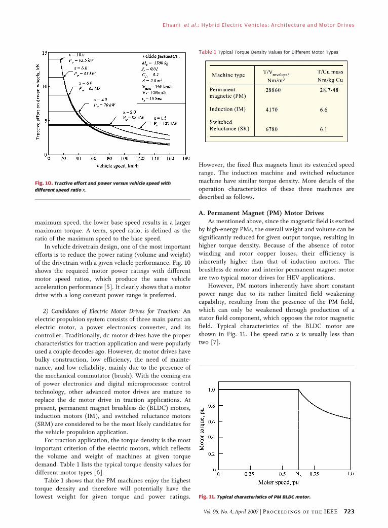
maximum speed, the lower base speed results in a larger
maximum torque. A term, speed ratio, is defined as theratio of the maximum speed to the base speed.
In vehicle drivetrain design, one of the most important
efforts is to reduce the power rating (volume and weight)
of the drivetrain with a given vehicle performance. Fig. 10
shows the required motor power ratings with different
motor speed ratios, which produce the same vehicle
acceleration performance [5]. It clearly shows that a motor
drive with a long constant power range is preferred.
2) Candidates of Electric Motor Drives for Traction: An
electric propulsion system consists of three main parts: an
electric motor, a power electronics converter, and its
controller. Traditionally, dc motor drives have the proper
characteristics for traction application and were popularly
used a couple decodes ago. However, dc motor drives have
bulky construction, low efficiency, the need of mainte-nance, and low reliability, mainly due to the presence of
the mechanical commutator (brush). With the coming era
of power electronics and digital microprocessor control
technology, other advanced motor drives are mature to
replace the dc motor drive in traction applications. At
present, permanent magnet brushless dc (BLDC) motors,
induction motors (IM), and switched reluctance motors
(SRM) are considered to be the most likely candidates forthe vehicle propulsion application.
For traction application, the torque density is the most
important criterion of the electric motors, which reflects
the volume and weight of machines at given torque
demand. Table 1 lists the typical torque density values for
different motor types [6].
Table 1 shows that the PM machines enjoy the highest
torque density and therefore will potentially have thelowest weight for given torque and power ratings.
However, the fixed flux magnets limit its extended speed
range. The induction machine and switched reluctancemachine have similar torque density. More details of the
operation characteristics of these three machines are
described as follows.
A. Permanent Magnet (PM) Motor DrivesAs mentioned above, since the magnetic field is excited
by high-energy PMs, the overall weight and volume can be
significantly reduced for given output torque, resulting inhigher torque density. Because of the absence of rotor
winding and rotor copper losses, their efficiency is
inherently higher than that of induction motors. The
brushless dc motor and interior permanent magnet motor
are two typical motor drives for HEV applications.
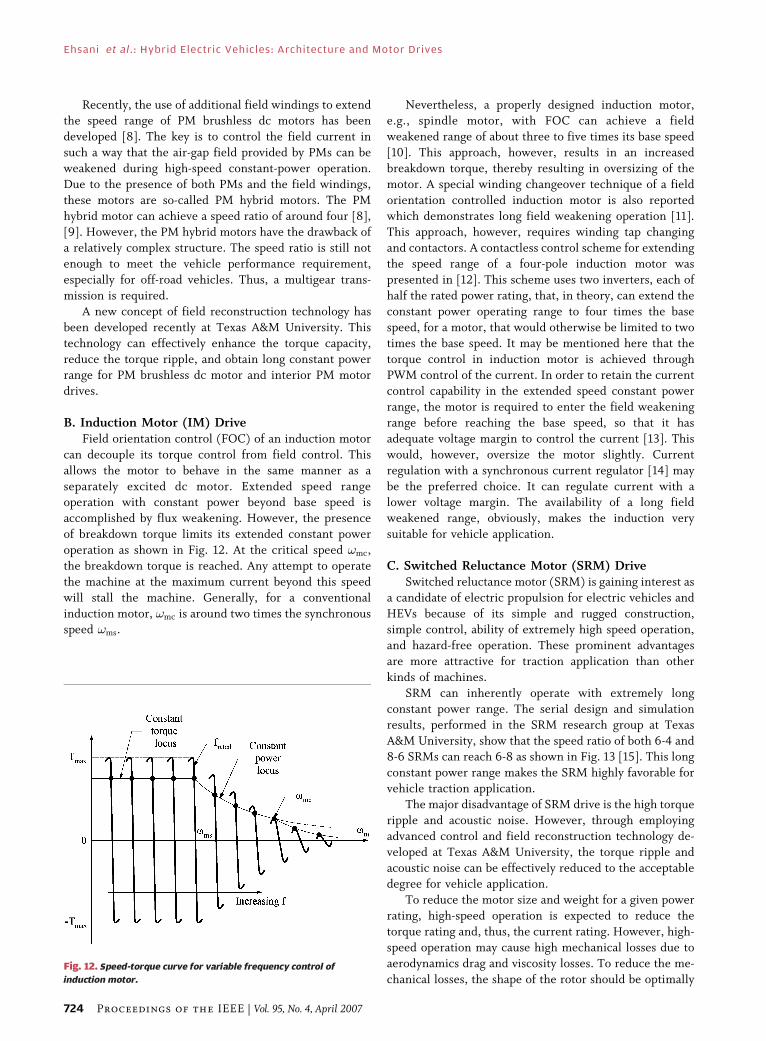
However, PM motors inherently have short constant
power range due to its rather limited field weakening
capability, resulting from the presence of the PM field,which can only be weakened through production of a
stator field component, which opposes the rotor magnetic
field. Typical characteristics of the BLDC motor are
shown in Fig. 11. The speed ratio x is usually less than
two [7].
Table 1 Typical Torque Density Values for Different Motor Types
Fig. 10. Tractive effort and power versus vehicle speed with
different speed ratio x.
Fig. 11. Typical characteristics of PM BLDC motor.
Ehsani et al.: Hybrid Electric Vehicles: Architecture and Motor Drives
Vol. 95, No. 4, April 2007 | Proceedings of the IEEE 723
Recently, the use of additional field windings to extendthe speed range of PM brushless dc motors has been
developed [8]. The key is to control the field current in
such a way that the air-gap field provided by PMs can be
weakened during high-speed constant-power operation.
Due to the presence of both PMs and the field windings,
these motors are so-called PM hybrid motors. The PM
hybrid motor can achieve a speed ratio of around four [8],
[9]. However, the PM hybrid motors have the drawback ofa relatively complex structure. The speed ratio is still not
enough to meet the vehicle performance requirement,
especially for off-road vehicles. Thus, a multigear trans-
mission is required.
A new concept of field reconstruction technology has
been developed recently at Texas A&M University. This
technology can effectively enhance the torque capacity,
reduce the torque ripple, and obtain long constant powerrange for PM brushless dc motor and interior PM motor
drives.
B. Induction Motor (IM) DriveField orientation control (FOC) of an induction motor
can decouple its torque control from field control. This
allows the motor to behave in the same manner as a
separately excited dc motor. Extended speed rangeoperation with constant power beyond base speed is
accomplished by flux weakening. However, the presence
of breakdown torque limits its extended constant power
operation as shown in Fig. 12. At the critical speed !mc,
the breakdown torque is reached. Any attempt to operate
the machine at the maximum current beyond this speed
will stall the machine. Generally, for a conventional
induction motor, !mc is around two times the synchronousspeed !ms.
Nevertheless, a properly designed induction motor,e.g., spindle motor, with FOC can achieve a field
weakened range of about three to five times its base speed
[10]. This approach, however, results in an increased
breakdown torque, thereby resulting in oversizing of the
motor. A special winding changeover technique of a field
orientation controlled induction motor is also reported
which demonstrates long field weakening operation [11].
This approach, however, requires winding tap changingand contactors. A contactless control scheme for extending
the speed range of a four-pole induction motor was
presented in [12]. This scheme uses two inverters, each of
half the rated power rating, that, in theory, can extend the
constant power operating range to four times the base
speed, for a motor, that would otherwise be limited to two
times the base speed. It may be mentioned here that the
torque control in induction motor is achieved throughPWM control of the current. In order to retain the current
control capability in the extended speed constant power
range, the motor is required to enter the field weakening
range before reaching the base speed, so that it has
adequate voltage margin to control the current [13]. This
would, however, oversize the motor slightly. Current
regulation with a synchronous current regulator [14] may
be the preferred choice. It can regulate current with alower voltage margin. The availability of a long field
weakened range, obviously, makes the induction very
suitable for vehicle application.
C. Switched Reluctance Motor (SRM) DriveSwitched reluctance motor (SRM) is gaining interest as
a candidate of electric propulsion for electric vehicles and
HEVs because of its simple and rugged construction,simple control, ability of extremely high speed operation,
and hazard-free operation. These prominent advantages
are more attractive for traction application than other
kinds of machines.
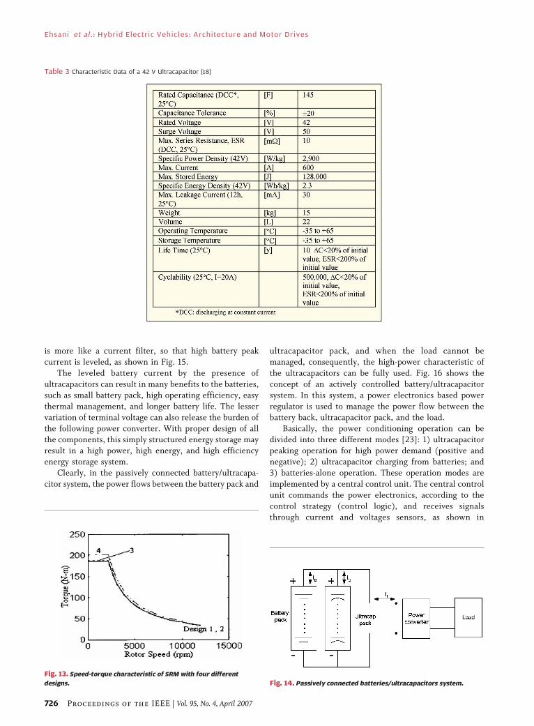
SRM can inherently operate with extremely long
constant power range. The serial design and simulation
results, performed in the SRM research group at Texas
A&M University, show that the speed ratio of both 6-4 and8-6 SRMs can reach 6-8 as shown in Fig. 13 [15]. This long
constant power range makes the SRM highly favorable for
vehicle traction application.
The major disadvantage of SRM drive is the high torque
ripple and acoustic noise. However, through employing
advanced control and field reconstruction technology de-
veloped at Texas A&M University, the torque ripple and
acoustic noise can be effectively reduced to the acceptabledegree for vehicle application.
To reduce the motor size and weight for a given power
rating, high-speed operation is expected to reduce the
torque rating and, thus, the current rating. However, high-
speed operation may cause high mechanical losses due to
aerodynamics drag and viscosity losses. To reduce the me-
chanical losses, the shape of the rotor should be optimallyFig. 12. Speed-torque curve for variable frequency control of
induction motor.
Ehsani et al. : Hybrid Electric Vehicles: Architecture and Motor Drives
724 Proceedings of the IEEE | Vol. 95, No. 4, April 2007

designed especially for SRM drive, where the rotor isshaped like a gear, which causes high aerodynamic drag at
high speed.
IV. ENERGY STORAGE
1) Chemical Batteries and Ultracapacitors: Energy storage
is another important component in a hybrid electricdrivetrain. It is required to have sufficient peak power and
energy capacity to support the operation of the vehicle. At
present, almost all the vehicles use chemical batteries as
their energy storage. Table 2 shows the status of battery
systems potentially available for EVs and HEVs [16].
It can be seen that although specific energies are high
in advanced batteries, the specific power does not have
any significant improvement. About 300 W/kg might bethe optimistic estimate. Recently, SAFT has reported their
Li-ion high-power and high-energy batteries with about
4000 and 600 W/kg, respectively. However, their prac-
ticality and cost reduction in the future need to be further
proven.
Ultracapacitor is another candidate as potential energy
storage for hybrid vehicles. The ultracapacitor is charac-
terized by high specific power, high efficiency, excellenttemperature adaptability, and long service life. However, it
has suffered from very limited specific energy. The
characteristics of a 42-V ultracapacitor pack specifically
designed for HEV and produced by Montena Company are
listed in Table 3 [18]. Maxwell Technologies [19] havereportedly developed 2700-F ultracapacitors with 2.5-V
cell voltage, 2.55-kW/kg specific power, and 3.23-Wh/kg
specific energy, respectively. It is believed that the unit
power cost of the ultracapacitor is lower than that of
batteries. However, due to its low specific energy and
dependence of voltage on the state-of-charge, it is difficult
to use ultracapacitors alone as the energy storage on hybrid
vehicles. The most promising approach is to hybridize theultracapacitors with other energy storages, such as
batteries and flywheel, which will be discussed in the
following sections.
2) Hybrid Energy Storage: Compared to ultracapacitors,
the chemical has a much higher specific energy but much
less specific power. When chemical batteries or an
ultracapacitor alone are taken as the energy storage, heavyweight will be unavoidable, because the former needs
large weight to meet the power requirement and the latter
needs weight to meet the energy requirement. However,
when both of them are properly combined, an energy
storage with high power and high energy can be obtained.
This energy storage is called hybrid energy storage, in
which the batteries supply the energy demand and the
ultracapacitors supply the power demand.The most straightforward approach is to directly
connect ultracapacitors to batteries as shown in Fig. 14.
This configuration has the simplest structure and no
control unit is needed. The behavior of the ultracapacitors
Table 2 Status of Chemical Battery Systems for EV
Ehsani et al.: Hybrid Electric Vehicles: Architecture and Motor Drives
Vol. 95, No. 4, April 2007 | Proceedings of the IEEE 725
is more like a current filter, so that high battery peak
current is leveled, as shown in Fig. 15.
The leveled battery current by the presence of
ultracapacitors can result in many benefits to the batteries,
such as small battery pack, high operating efficiency, easy
thermal management, and longer battery life. The lesser
variation of terminal voltage can also release the burden of
the following power converter. With proper design of allthe components, this simply structured energy storage may
result in a high power, high energy, and high efficiency
energy storage system.
Clearly, in the passively connected battery/ultracapa-
citor system, the power flows between the battery pack and
ultracapacitor pack, and when the load cannot be
managed, consequently, the high-power characteristic of
the ultracapacitors can be fully used. Fig. 16 shows the
concept of an actively controlled battery/ultracapacitor
system. In this system, a power electronics based power
regulator is used to manage the power flow between the
battery back, ultracapacitor pack, and the load.
Basically, the power conditioning operation can bedivided into three different modes [23]: 1) ultracapacitor
peaking operation for high power demand (positive and
negative); 2) ultracapacitor charging from batteries; and
3) batteries-alone operation. These operation modes are
implemented by a central control unit. The central control
unit commands the power electronics, according to the
control strategy (control logic), and receives signals
through current and voltages sensors, as shown in
Fig. 13. Speed-torque characteristic of SRM with four different
designs. Fig. 14. Passively connected batteries/ultracapacitors system.
Table 3 Characteristic Data of a 42 V Ultracapacitor [18]
Ehsani et al. : Hybrid Electric Vehicles: Architecture and Motor Drives
726 Proceedings of the IEEE | Vol. 95, No. 4, April 2007

Fig. 11. The control objectives are: 1) to meet the power
requirement; 2) to keep the battery current in a preset
region; and 3) to keep the battery SOC in its middle region
(0.4 to 0.6 for example), in which the battery efficiencies
are usually optimized.
This system can potentially fully use the high power
property of the ultracapacitors, therefore resulting in asmall battery pack. The actively controlled battery current
can potentially lead to more efficient battery operation and
easier thermal management.
V. CONCLUSION
This paper systematically reviews the state of the art of
modern hybrid vehicle technologies, including architec-tures, electric motor drives, and energy storage. For the
architectures, series, parallel, and series–parallel are the
most commonly used architectures. For the advantages
and disadvantages, series hybrid configuration is mostly
used in heavy vehicles, military vehicles, and buses. On the
other hand, parallel and series–parallel are mostly used in
small automobiles, such as passenger cars. Regarding to
the electric motor drives, a long constant power region cansignificantly reduce the power rating of the electric system
and therefore reduce the total weight of the system. A
hybrid energy storage combining chemical batteries and
ultracapacitors will certainly be the most promising way to
meet the energy and power demands with a compact and
lightweight structure. h
RE FERENCES
[1] M. Ehsani, Y. Gao, S. Gay, and A. Amade,Modern Electric, Hybrid Electric, and Fuel CellVehicles: Fundamentals, Theory, and Design.Boca Raton, FL: CRC, Nov. 2004.
[2] M. Ehsani, Y. Gao, and K. L. Butler,BApplication of electrically peaking hybrid(ELPH) propulsion system to a full sizepassenger car with simulated designverification,’’ IEEE Trans. VehicularTechnol., vol. 40, no. 6, Nov. 1999.
[3] C. C. Chan and K. T. Chau, Modern ElectricVehicle Technology. New York: Oxford Univ.Press, 2001.
[4] J. Y. Wong, Theory of Ground Vehicle.New York: Wiley, 1978, pp. 132–133.
[5] M. Ehsani, Y. Gao, and S. Gay,BCharacterization of electric motordrives for traction applications,[ in Proc.Industrial Electronics Society, IECON ’03,Nov. 2–6, 2003, pp. 891–896.
[6] Z. Rahman, K. L. Butler, and M. Ehsani,BEffect of extended-speed, constant-poweroperation of electric drives on the designand performance of EV propulsion system,[presented at the SAE Future Car Congr.,Apr. 2000, 2001-01-0699.
[7] K. M. Rahman and M. Ehsani, BPerformanceanalysis of electric motor drives for electricand hybrid electric vehicle application,’’Power Electron. Transportation, pp. 49–56,1996.
[8] C. C. Chen and K. T. Chau, Modern ElectricVehicle Technology. New York: Oxford Univ.Press, 2001, pp. 122–133.
[9] C. C. Chan, K. T. Jiang, J. Z. Xia, W. Zhu, andR. Zhang, BNovel permanent magnet motordrive for electric vehicles,’’ IEEE Trans. Indust.Electron., vol. 43, no. 2, Apr. 1996.
[10] B. P. Ferraris and M. Lazzari, BA newdesign criteria for spindle inductionmotors controlled by field orientatedtechnique,’’ Electric Machine Power Syst.,vol. 21, pp. 171–182, 1993.
[11] T. Kume, T. Iwakane, T. Yoshida, andI. Nagai, BA wide constant powerrange vector-controlled ac motordrive using winding changeovertechnique,’’ IEEE Trans. IndustryApplic., vol. 27, no. 5, pp. 934–939,Sept./Oct. 1991.
[12] Osama and T. A. Lipo, BA new invertercontrol scheme for induction motordrives requiring speed range,[ in Proc.
IEEE-IAS Annu. Meeting, Orlando, FL, 1995,pp. 350–355.
[13] R. J. Kerkman, T. M. Rowan, andD. Leggate, BIndirect field-orientedcontrol of an induction motor in the filedweakened region,’’ IEEE Trans. IndustryApplic., vol. 28, no. 4, pp. 850–857.
[14] T. M. Rowan, R. J. Kerman, and T. A. Lipo,BOperation of a naturally sampled currentregulation in the transition mode,’’ IEEETrans. Industry Applic., vol. 23, no. 4,pp. 587–595, Jul./Aug. 1987.
[15] K. M. Rahman, B. Fahimi, G. Suresh,A. V. Rajarathnam, and M. Ehsani,BAdvanced of switched reluctance motorapplications to EV and HEV: Design andcontrol issues,’’ IEEE Trans. Industry Applic.,vol. 36, no. 1, pp. 111–121, Jan./Feb. 2000.
[16] D. A. J. Rand, R. Woods, and R. M. Dell,Batteries for Electric Vehicles, Soc. AutomotiveEng., 1998.
[17] [Online]. Available: www.saftbatteries.com/automotive/uk/f/f.htm: SAFT Batteries.
[18] Montena Components. [Online]. Available:www.montena.com.
[19] Maxwell Technologies. [Online]. Available:www.maxwell.com.
Fig. 15. Battery current leveled by passively connected
ultracapacitors.
Fig. 16. Conceptual illustration of actively controlled battery/
ultracapacitor system.
Ehsani et al.: Hybrid Electric Vehicles: Architecture and Motor Drives
Vol. 95, No. 4, April 2007 | Proceedings of the IEEE 727

[20] J. M. Miller, BHybrid electric vehiclepropulsion system architecture ofthe e-CVT type,’’ IEEE Trans. PowerElectron., vol. 21, no. 3, pp. 756–767,May 2006, 2005-2416-SI.
[21] J. M. Miller, M. Ehsani, and Y. Gao,BUnderstanding power flows in HEVeCVT’s with ultracapacitor boostingusing simplorer,[ in IEEE Power
Propulsion Conf., Illinois Inst. Technol.,Chicago, IL, Sep. 7–9, 2005.
[22] Y. Gao, M. Ehsani, and J. M. Miller,BHybrid electric vehicle overview andstate of the art,[ in Proc. IEEE Int.Symp. Industrial Electronics, ISIE’05,Dubrovnik, Croatia, Jun. 20–23, 2005,mini-track on automotive control,MTAC.
[23] J. M. Miller and M. Everett, BUltra-capacitorplus battery energy storage systemsizing methodology for HEV powersplitelectronic CVT’s,[ in Proc. IEEE Int.Symp. Industrial Electronics, ISIE’05,Dubrovnik, Croatia, Jun. 20–23, 2005,mini-track on automotive control,MTAC.
ABOUT THE AUT HORS
Mehrdad Ehsani (Fellow, IEEE) has been at Texas
A&M University, College Station, Texas since 1981,
where he has been the Robert M. Kennedy Pro-
fessor of electrical engineering and Director of
Advanced Vehicle Systems Research Program since
2004. He is the author of over 300 publications in
specialty power systems, pulsed-power supplies,
high-voltage engineering, power electronics and
motor drives, and automotive power and pro-
pulsion systems. He is the Coauthor of several
books on power electronics, motor drives, vehicle power and propulsion
systems, and a contributor to an IEEE Guide for Self-Commutated
Converters and many monographs. He is the author of over 20 U.S. and
EC patents. His current research work is in power electronics, motor
drives, hybrid electric vehicles, and vehicle power systems.
Dr. Ehsani has been a member of IEEE Power Electronics Society
AdCom, past Chairman of PELS Educational Affairs Committee, past
Chairman of IEEE-IAS Industrial Power Converter Committee and
Founding Chairman of the IEEE Myron Zucker Student-Faculty Grant
program. He was the General Chair of IEEE Power Electronics Specialist
Conference for 1990. He is an IEEE Industrial Electronics Society and
Vehicular Technology Society Distinguished Speaker and IEEE Industry
Applications Society past Distinguished Lecturer. He has been the
Associate Editor of IEEE Transactions of IES and IEEE VEHICLE TECHNOLOGY
SYSTEMS. He is the founder of IEEE Power and Propulsion Conference of
Vehicular Technology and Power Electronics Societies and the Chairman
of its Steering Committee. He was elected to the Board of Governors of
IEEE-VTS in 2003. He also serves on the IEEE Power Electronics Society
Administrative Committee. In 2005, he was elected Fellow of the Society
of Automotive Engineers (SAE). He is also a registered professional
engineer in the State of Texas. He has been the recipient of the Prize
Paper Awards in Static Power Converters and motor drives at the IEEE-
Industry Applications Society 1985, 1987, and 1992 Annual Meetings. In
1992, he was named the Halliburton Professor in the College of
Engineering at Texas A&M. In 1994, he was also named the Dresser
Industries Professor at the same college. In 2001, he was named the Dow
Chemical Faculty Fellow of the College of Engineering at Texas A&M
University. In 2001, he also received the James R. Evans Avant Garde
Award from IEEE Vehicular Technology Society. He is the recipient of
IEEE Field Award in Undergraduate Teaching in 2003.
Yimin Gao received the B.S., M.S., and Ph.D.
degrees in automotive engineering in 1982, 1986,
and 1991 respectively, all from Jilin University of
Technology, China. He specialized in the develop-
ment, design and manufacturing of automobiles.
From 1991 to 1995, he was an Associate
Professor and Automotive Design Engineer in the
Automotive Engineering College, Jilin University
of Technology. He joined the Advanced Vehicle
Systems Research Program at Texas A&M Univer-
sity, College Station, in 1995. Since then, he has been working in this
program as a Research Associate on the research and development of
electric and hybrid electric vehicles. His research interests include the
fundamentals, architecture, control, modeling, and systematic design of
electric and hybrid electric vehicles.
John M. Miller (Fellow, IEEE) received the BSEE
degree from the University of Arkansas, Fayette-
ville, in 1976, the MSEE degree from Southern
Methodist University, Dallas, TX, in 1979, and the
Ph.D. degree from Michigan State University, East
Lansing, in 1983, all in electrical engineering.
In 2006, he joined Maxwell Technologies as
Vice President of advanced transportation appli-
cations. In this capacity, he supports strategic
marketing and product applications through sys-
tems level analysis, modeling, simulation, and customer collaboration in
emerging technical areas. He brings Maxwell Technologies a systems
perspective and works closely with the engineering and business sides of
the company. He has authored over 120 publications on automotive
electrical and electronic systems, utility power systems and transporta-
tion systems and holds 51 U.S. patents. He is author of the book
Propulsion Systems for Hybrid Vehicles (IEE Press Power & Energy Series
PO045, London, U.K., 2003) and Coauthor of two additional books:
Handbook of Automotive Power Electronics and Motor Drives, (Marcel
Dekker, 2004) and Vehicular Electric Power Systems: Land, Sea, Air, and
Space Vehicles, (Marcel Dekker, December 2003). He also developed the
IEEE Expert Now Interactive Course: Exploring the Electronic Continu-
ously Variable Transmission.
Dr. Miller is a registered and practicing Professional Engineer in
Michigan since 1980 and an IEEE Power Electronics Society Distinguished
Lecturer and Editor-in-Chief of the Power Electronics Society newsletter.
Ehsani et al. : Hybrid Electric Vehicles: Architecture and Motor Drives
728 Proceedings of the IEEE | Vol. 95, No. 4, April 2007