INVESTIGATION OF THE VENTILATION FLOW IN A GAS TURBINE ...
10
Paper ID: ETC2019-438 Proceedings of 13th European Conference on Turbomachinery Fluid dynamics & Thermodynamics ETC13, April 8-12, 2019; Lausanne, Switzerland INVESTIGATION OF THE VENTILATION FLOW IN A GAS TURBINE PACKAGE ENCLOSURE J. Kowalski 1* - F. di Mare 1 - S. Theis 2 - A. Wiedermann 2 , M. Lange 3 , R. Mailach 3 1 Chair of Thermal Turbomachines and Aeroengines, Ruhr-Universit¨ at Bochum, Germany 2 MAN Energy Solutions SE, Oberhausen, Germany 3 Chair of Turbomachinery and Flight Propulsion, Technische Universit¨ at Dresden, Germany * Corresponding Author: [email protected] ABSTRACT The ventilation flow of a gas turbine enclosure was investigated both experimentally and numerically in a scaled test rig. Its gas turbine components were inactive and mainly functioned as flow obstructions. Measurements were used to provide realistic boundary conditions and verification data for URANS CFD investigations. In the test rig the active generator cooling flow was created by several fans, modelled by momentum sources in the CFD. Two different modelling approaches were compared to PIV data. The modelling of the ventilation flow was found to impact flow regions nearby the generator but also far downstream with one method showing better agreement with the experiment. Examining the flow predicted by the chosen CFD model, no relevant backflow from the engine to the upstream gear section could be observed. Therefore, the investigation of stagnation regions was focused on the engine section to identify worst case leakage configurations for future investigations. KEYWORDS CFD, URANS, Gas Turbine, Enclosure Ventilation, Explosion Safety NOMENCLATURE Abbreviations CFD Computational Fluid Dynamics CPT Combined pressure and temperature EP Evaluation plane GGI General Grid Interface IGCF Internal generator cooling flow MEVF Main enclosure ventilation flow PIV Particle Image Velocimetry SST Shear Stress Transport model TFT Through flow time TRM Test rig CFD model URANS Unsteady Reynolds averaged Navier Stokes equations Latin symbols c [m/s] Velocity magnitude u [m/s] Velocity component in x-direction y + [-] Dimensionless wall distance Subscripts xz, yz [m/s] Projected velocity magnitude INTRODUCTION Installing gas turbines in an acoustic enclosure is common for engines of intermediate power class, i.e. up to 25 MW. These enclosures reduce the noise emitted by the engine and protect it from weather conditions in case of an outdoor installation but also require special consideration regarding explosion safety. Even though no explosive atmosphere exists during regular engine OPEN ACCESS Downloaded from www.euroturbo.eu 1 Copyright c by the Authors
Transcript of INVESTIGATION OF THE VENTILATION FLOW IN A GAS TURBINE ...

Paper ID: ETC2019-438 Proceedings of 13th European Conference on Turbomachinery Fluid dynamics & ThermodynamicsETC13, April 8-12, 2019; Lausanne, Switzerland
INVESTIGATION OF THE VENTILATION FLOW IN A GASTURBINE PACKAGE ENCLOSURE
J. Kowalski 1∗ - F. di Mare 1 - S. Theis 2 - A. Wiedermann 2,M. Lange 3, R. Mailach 3
1 Chair of Thermal Turbomachines and Aeroengines, Ruhr-Universitat Bochum, Germany
2 MAN Energy Solutions SE, Oberhausen, Germany
3 Chair of Turbomachinery and Flight Propulsion, Technische Universitat Dresden, Germany∗ Corresponding Author: [email protected]
ABSTRACTThe ventilation flow of a gas turbine enclosure was investigated both experimentally andnumerically in a scaled test rig. Its gas turbine components were inactive and mainlyfunctioned as flow obstructions. Measurements were used to provide realistic boundaryconditions and verification data for URANS CFD investigations. In the test rig the activegenerator cooling flow was created by several fans, modelled by momentum sources in theCFD. Two different modelling approaches were compared to PIV data. The modelling ofthe ventilation flow was found to impact flow regions nearby the generator but also fardownstream with one method showing better agreement with the experiment. Examiningthe flow predicted by the chosen CFD model, no relevant backflow from the engine tothe upstream gear section could be observed. Therefore, the investigation of stagnationregions was focused on the engine section to identify worst case leakage configurations forfuture investigations.
KEYWORDSCFD, URANS, Gas Turbine, Enclosure Ventilation, Explosion Safety
NOMENCLATUREAbbreviationsCFD Computational Fluid DynamicsCPT Combined pressure and temperatureEP Evaluation planeGGI General Grid InterfaceIGCF Internal generator cooling flowMEVF Main enclosure ventilation flowPIV Particle Image VelocimetrySST Shear Stress Transport modelTFT Through flow time
TRM Test rig CFD modelURANS Unsteady Reynolds averaged
Navier Stokes equationsLatin symbolsc [m/s] Velocity magnitudeu [m/s] Velocity component
in x-directiony+ [-] Dimensionless wall distanceSubscriptsxz, yz [m/s] Projected velocity magnitude
INTRODUCTIONInstalling gas turbines in an acoustic enclosure is common for engines of intermediate powerclass, i.e. up to 25 MW. These enclosures reduce the noise emitted by the engine and protect itfrom weather conditions in case of an outdoor installation but also require special considerationregarding explosion safety. Even though no explosive atmosphere exists during regular engine
OPEN ACCESSDownloaded from www.euroturbo.eu
1 Copyright c© by the Authors

operation, fuel leakages due to system failures might occur and must be taken into account.Usually, gas turbine enclosures are actively ventilated to dilute and to extract possible leakages.This dilution ventilation is regarded by Ivings et al. (2004) as the most common safety measureto prevent explosions in gas turbine enclosures. Nevertheless, studies by the British Health andSafety Executive (2008) revealed the occurrence of 134 gas leakages in enclosures within theUK alone during a period of 13 years, resulting in a total of 19 incidents of actual fuel ignition.Therefore, careful ventilation flow design is crucial for safe engine operation. Usually, individ-ual investigation of each engine’s ventilation flow configuration is required. Two methods arecommonly adopted. The first approach is to model a fuel jet leakage analytically and to evaluatethe size of the fuel/air mixture cloud above a certain concentration level for a given ventilationflow rate, as described by Ivings et al. (2008). The second approach is to model the whole enclo-sure including an occurring leakage jet using Computational Fluid Dynamics (CFD) methods.While the first method represents a simplified approach, it was found to be rather conservativeby Gant and Ivings (2005). However, even though CFD considers very complex phenomena,including their respective interaction mechanisms, choosing suitable model parameters as wellas the application of appropriate boundary condition is still crucial to acquire reliable flow fielddata. Hence, detailed measurements are needed to verify the chosen CFD model.
Experimental investigations of an enclosure ventilation flow were conducted by Vahidi et al.(2006). They developed an enclosure test rig with a model scale of 1:6, which they operatedwith heated engine walls. Their test rig featured a very simple geometry and piping systemswere omitted completely. Though local pitot probe measurements were conducted, the focus oftheir work was on the leakage concentration of CO2 as a replacement for natural gas and infor-mation given about the flow field mainly results from CFD data. Based on these studies theycarried out numerical simulations and derived a design procedure for package ventilation sys-tems (Bagheri and Vahidi 2006). Further investigations were conducted by Ivings et al. (2008).They developed a test enclosure with multiple in- and outlets as well as a large obstruction inwhich they carried out different leakage scenarios using a tracer gas with the same molecularmass and density as CH4. The experimental results were then used to verify their CFD re-sults. As in the aforementioned work, the test configuration was rather simple and apart fromconcentration data, no detailed flow field information is provided.
To create detailed ventilation flow field data, a cooperation project among MAN EnergySolutions SE, the Technische Universitat Dresden and the Ruhr-Universitat Bochum was startedwhereby a scaled test rig simulating a gas turbine package was developed and investigatedexperimentally. The experimental data was then used to set up and to verify a CFD model ofthe enclosure ventilation flow, which shall be discussed in detail in this paper.
EXPERIMENTAL INVESTIGATIONThe test rig was designed based on a comprehensive similarity study which was conductedutilizing analytical as well as CFD methods. The results were documented in detail by Kowalskiet al. (2017). Based on these studies, a model scale of 1:3 was chosen along with appropriateoperation conditions for the investigations. The test rig and the experimental setup shall bediscussed in the following sections.
Experimental FacilityThe test rig features the main engine components such as the gas turbine, gear, generator aswell as extensive pipework of the fuel and oil system, as shown in figure 1a. The gas turbine
2

components are inactive and mainly function as flow obstructions. However, the engine can beoutfitted with heating elements to include heat transfer and leakage gas can be injected via thefuel system piping, as illustrated in figure 1b. For the results discussed in this paper, the test rigwas operated in Ma-similarity conditions, adiabatic wall conditions and without leakage. Thewhole power package is placed in an enclosure, which features several easily removable windowsegments for Particle Image Velocimetry (PIV) measurements as well as maintenance work. Togenerate the main enclosure ventilation flow (MEVF), the test rig is equipped with four dualstage counter-rotating fans. As in the actual engine, they are set up in a parallel-path air flowarrangement with two fans at the inlet and two at the outlet duct, which allows the investigationof realistic fan failure scenarios. The generator of the actual engine is actively ventilated forcooling purpose. This internal generator cooling flow (IGCF) must be distinguished from theMEVF. During the design process the influence of the IGCF on the MEVF became evident.Hence, the test rig’s generator is also actively ventilated by a total of eight small-scale high-performance fans. As can be seen in figure 1a, the enclosure inlet fan ducts are aligned directlytowards the generator flow inlet. This results in the IGCF consisting partially of the MEVF.The fraction of the MEVF, which does not enter the generator, escapes either towards the top orthe sides of the generator, where it interacts with the IGCF when reentering the enclosure (seefigure 1b).
Dual-Stage Counter-Rotating Fans (8 Single Stages in Total)
Gas Turbine (Red) Fuel System (Yellow)
Gear and Generator (Blue)Oil System (Green)
Easily Removable Window Segments (Borosilicate Glass)
PackageEnclosure
Probe Setup 1
Probe Setup 1
Probe Setup 2
(a) CAD model
Main Enclosure Ventilation Flow (MEVF)
Partial Flow Evading Up- wards and Sideways
Internal Generator Cooling Flow (IGCF)
Mixing of Main Ventilation Flowand Generator Cooling Flow
Possible Leakage Positions and Jet Directions (Future Work)
Thermal Buoyancy(Future Work)
(b) Flow phenomena of interest
Figure 1: Downscaled (1:3) package enclosure test rig developed by Kowalski et al. (2017)
Measurement SetupThe test rig features four combined total pressure - total temperature (CPT) probes, one ateach enclosure in- and outlet duct. For temperature measurements the pitot tube is combinedwith a Type-T thermocouple (probe setup 1). The CPT probes can be traversed throughout thewhole duct cross section at two circumferential positions. The total pressure and temperatureprofiles at the inlet ducts were used to measure the MEVF rate. To obtain velocity data from thepitot measurements, each in- and outlet duct also features four pressure taps for static pressuremeasurements (probe setup 1). The IGCF can be monitored with a pitot rake consisting of10 individual pitot tubes mounted in front of the generator inlet (probe setup 2), which can betraversed laterally. Pressure signals are transferred to two pressure transducer arrays (ScanivalveZOC17IP/8PX) and are recorded by a NI PXI data acquisition system, placed in a controlledtemperature room.
Flow field measurements were conducted using a Dantec 2D2C PIV system featuring aLitron Bernoulli laser with a repetition rate of 15 Hz and an energy output of 200 mJ per pulse
3

at 532 nm and an Andor HiSense Zyla 5.5 sCMOS camera with 5 megapixels resolution and16 bit dynamic range. Data was processed with the Dantec Dynamics Studio software. Forseeding purpose, a DEHS aerosol was inserted into the MEVF at each inlet duct downstream ofthe pitot probe via two small tubes with several drilled holes. To align the PIV light sheet opticand camera, modular profile frames were attached on the package enclosure’s frame system.
Evaluation ProcedureFor measuring the MEVF rate, CPT probes were placed at 13 radial positions for each circum-ferential alignment. The probe positions were chosen so that each was placed on the meanradius of equally sized subsections in each duct’s cross section. Therefore, the individual mea-surements are automatically weighted according to their corresponding fractional part of theduct’s cross section and can be averaged arithmetically to determine the MEVF.
PIV data was processed using the Dantec Dynamics Studio software suite. After acquiringa set of double frame images, the images were masked if reflections occurred or if obstructionsprevented complete illumination of the whole measuring plane. Then the resulting mean foreach pixel’s grey scale value was calculated and subtracted from each individual image, thuseliminating background illumination. Afterwards, each double frame image was processedutilizing an Adaptive PIV approach with a 5 x 5 neighbor as well as velocity range validation.The resulting vector fields were then averaged arithmetically.
Test Rig Design Verification
Table 1: Comparison of target andmeasured volume flows
Unit MEVF IGCF
Target [m3/h] 5, 584 3, 111Exp. [m3/h] 5, 562 3, 163
Dev. [%] -0.4 +1.7
Although the pitot rake could be used for measuringthe IGCF, this was obtained from 46 individual PIVmeasurements near the generator top, which providea higher spatial resolution. For these measurements,the light sheet was inserted vertically into the testrig with the camera being positioned sideways. TheIGCF was obtained by evaluating the time averagedvelocity component u over the generator top height atthe same position as the pitot rake. The IGCF inflowprofile is illustrated in figure 4a. The results of the volume flow measurements are given intable 1 along with the target values from the design process as well as the relative deviation.The MEVF was found to be 0.4 % below the target value whereas the IGCF was 1.7 % toohigh. The reason the IGCF’s deviation was greater than the MEVF’s is due to the fact that theIGCF as well as the whole flow field around the generator is very sensitive to changes of thegenerator fan speed. Since the IGCF consists partly of the MEVF and they interact significantlywith each other, especially during reentry of the IGCF into the package enclosure. Therefore,changing the flow rate of the IGCF influences how the MEVF passes through and around thegenerator. Nevertheless, the deviation of the IGCF can be regarded as being sufficiently smalland the operation condition requirements to be fulfilled.
NUMERICAL INVESTIGATIONIn the following sections the CFD methods and results will be discussed. Therein, details aboutthe numerical method and modelling approach, the chosen spatial and temporal resolution, aswell as the numerical setup will be given. Best practice guidelines for numerical ventilationflow investigations were described by Ivings et al. (2003), which were considered within the
4
scope of this work. Although the main focus of this section will be on the verification process,the evaluations of the ventilation flow will be discussed as well.
Solution MethodThe CFD investigations were conducted using ANSYS CFX release 19.0, which is an un-structured solver utilizing a finite volume method. For convergence acceleration, the RANSequations are solved using an Algebraic Multigrid approach in conjunction with an IncompleteLower Upper factorization algorithm. For the temporal discretization a Second Order Back-ward Euler scheme was used. All simulations were carried out using the Shear Stress Transport(SST) k - ω turbulence model.
Spatial and Temporal Resolution
2 3
1
4
5
X Y
Z
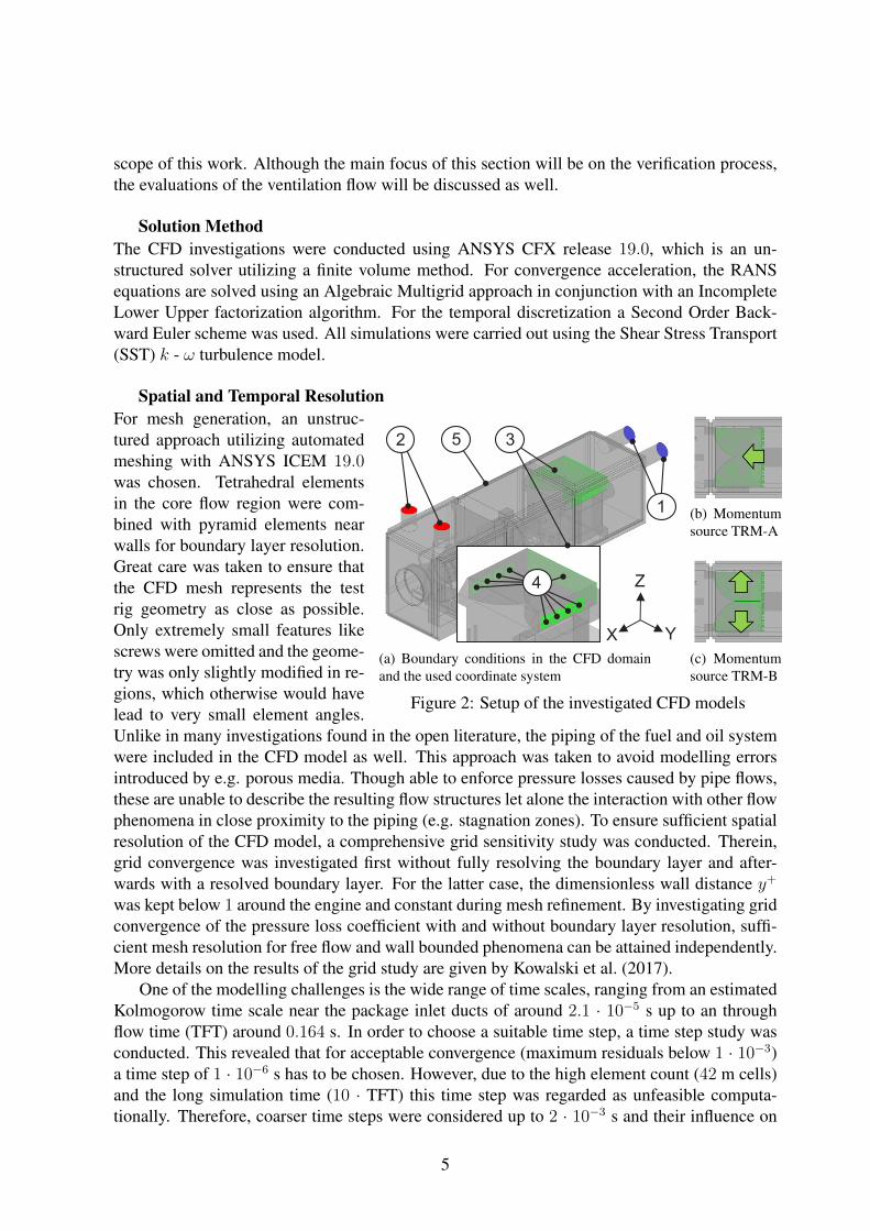
(a) Boundary conditions in the CFD domain ——and the used coordinate system
(b) Momentumsource TRM-A
(c) Momentumsource TRM-B
Figure 2: Setup of the investigated CFD models
For mesh generation, an unstruc-tured approach utilizing automatedmeshing with ANSYS ICEM 19.0was chosen. Tetrahedral elementsin the core flow region were com-bined with pyramid elements nearwalls for boundary layer resolution.Great care was taken to ensure thatthe CFD mesh represents the testrig geometry as close as possible.Only extremely small features likescrews were omitted and the geome-try was only slightly modified in re-gions, which otherwise would havelead to very small element angles.Unlike in many investigations found in the open literature, the piping of the fuel and oil systemwere included in the CFD model as well. This approach was taken to avoid modelling errorsintroduced by e.g. porous media. Though able to enforce pressure losses caused by pipe flows,these are unable to describe the resulting flow structures let alone the interaction with other flowphenomena in close proximity to the piping (e.g. stagnation zones). To ensure sufficient spatialresolution of the CFD model, a comprehensive grid sensitivity study was conducted. Therein,grid convergence was investigated first without fully resolving the boundary layer and after-wards with a resolved boundary layer. For the latter case, the dimensionless wall distance y+
was kept below 1 around the engine and constant during mesh refinement. By investigating gridconvergence of the pressure loss coefficient with and without boundary layer resolution, suffi-cient mesh resolution for free flow and wall bounded phenomena can be attained independently.More details on the results of the grid study are given by Kowalski et al. (2017).
One of the modelling challenges is the wide range of time scales, ranging from an estimatedKolmogorow time scale near the package inlet ducts of around 2.1 · 10−5 s up to an throughflow time (TFT) around 0.164 s. In order to choose a suitable time step, a time step study wasconducted. This revealed that for acceptable convergence (maximum residuals below 1 · 10−3)a time step of 1 · 10−6 s has to be chosen. However, due to the high element count (42 m cells)and the long simulation time (10 · TFT) this time step was regarded as unfeasible computa-tionally. Therefore, coarser time steps were considered up to 2 · 10−3 s and their influence on
5

the local velocity were investigated over a simulation time of 0.1 · TFT. This study revealedthat choosing coarser time steps than 1 · 10−6 s leads to a smoothing of the local velocity fluc-tuations. Regarding the time-averaged results, simulations with coarser time steps show goodagreement to the reference. However, concerning the stability of the simulation a time step of2 · 10−3 s was regarded as too coarse and therefore a time step of 2 · 10−4 s was found to be asuitable trade off between temporal accuracy, numerical stability and computation cost.
Numerical Setup
Table 2: Numerical setup overview
Parameter Description
Medium AirTurbulence model SST k-ωEnergy model IsothermalTime step 2 · 10−4 sSimulation time 1.64 s
Pos. Type Property
1 Inlet Velocity2 Outlet Static pressure3 Subdomain Momentum
source4 Interface GGI5 Wall No slip wall
Adiabatic
Two different model setups were investigated thatmainly differ in the way the IGCF is modelled. Abrief overview of the applied boundary conditionsis given in figure 2 and table 2. At the enclosure in-lets (1), the velocity profile obtained from the CPTprobe measurements is set for both ducts. At the en-closure outlets (2), the static pressure (slightly be-low atmospheric pressure) is set based on pressuretap measurements. To include the IGCF inducedby the generator fans, a subdomain approach wastaken (3) by modelling the fans via a global mo-mentum source. In the first test rig model TRM-A,the generator top consists of one single subdomainand the momentum source is induced in x-direction(figure 2b). In the second model TRM-B, the gen-erator top is split into two subdomains and the mo-mentum source is applied in opposing, outward fac-ing y-directions (figure 2c). For TRM-B, the twosubdomains are separated by a thin wall, as in theactual test rig. The subdomains are connected tothe enclosure domain by General Grid Interfaces (GGI) (4). All walls feature an adiabatic, no-slip boundary condition (5). Due to the test case being adiabatic and the low Ma-numbers, theisothermal energy model was chosen to speed up the solution process.
Model VerificationEP-GI (Gas Turbine Intake)
EP-PO (Package Outlet) X Y
Z
EP-GN (Generator)
EP-D (Diffusor)
Figure 3: Investigated evaluation planes
To verify the numerical results, both CFD modelsshall be compared to PIV data. The position of thecorresponding evaluation planes (EP) is shown infigure 3. The PIV images were evaluated as de-scribed beforehand, the CFD runs were averagedarithmetically over the whole simulation time. Theresults for EP-GN are given in figure 4 for thevelocity component u, which corresponds to theIGCF. Since u is oriented perpendicular to EP-GN,the distribution of u was obtained by 46 individualPIV measurements, in which the light sheet wasaligned in xz-direction and traversed laterally infront of the generator intake. The experiment (4a)
6

reveals, that each of the two inlet jets of the MEVF coheres before entering the generator top.The position of the jets in y-direction corresponds with the inlet duct axis but the left jet isslightly distorted and displaced upwards compared to the opposing jet. Another feature of theIGCF is the presence of a backflow in the middle of the generator intake. A portion of theMEVF entering the generator is not transported outwards by the generator fans but is redirectedto the generator intake by a guide plate. Despite the slight differences between the two jets, theIGCF can be described as rather symmetrical.
(a) PIV
(b) TRM-A
(c) TRM-B
Figure 4: Generator top inflow profile (EP-GN)
The IGCF could be matched integrallywith deviations of +6% (TRM-A) and +4%(TRM-B). This is mainly due to the high sen-sitivity of the flow field to the interaction ofthe MEVF and the IGCF around the genera-tor, as discussed beforehand. Generally, bothCFD results show the main IGCF features,i.e. the occurrence of the two jets as well asa backflow region but they also differ fromeach other. When the results of TRM-A (4b)are compared to the experiment, it becomesevident that the backflow region is shifted to-wards the left jet, which in return is displacedtowards the side of the generator. Not onlydoes this result in a quenching of the left jetprofile, the position of the shear layer be-tween the inflow and backflow differs signifi-cantly from the experimental results. Whenregarding TRM-B (4c), the position of thebackflow region and the shear layer is in bet-ter agreement with the experimental data. It must be noted that for TRM-B a recirculationregion can be observed in the upper middle section of the EP. This flow structure could not beobserved in the experiment, and results from the backflow exiting the right side of the generatortop. However, TRM-B is regarded to be in better accordance to the experiment than TRM-A.
In addition to the generator intake velocity, further PIV measurements have been comparedto the numerical results. To ensure comparability of the PIV and CFD data, the magnitude ofthe velocity vector projected on the EP (e.g. cxz) will be examined. When investigating the flowfield near the enclosure exit (figure 5a-5c), the PIV data shows that the flow accelerates as itis sucked towards the package outlet and that it enters the EP diagonally, as it originates fromoverflowing the gas turbine components. Each CFD model shows reasonable agreement withthe experimental data, both in the position of the suction area as well as the velocity magnitude.For each CFD model a more shallow inflow angle compared to the experiment occurs. Herein,both models give similar results.
By investigating the low velocity flow region below the gas turbine diffusor (figure 5d-5f),the PIV data reveals that the flow enters the EP rather slowly coming from the bottom sectionbelow the diffusor and is accelerated while flowing diagonally towards the enclosure outlet.TRM-A overestimates the velocity magnitude of the flow entering the investigated region andit enters facing downwards in contrast to the experimental findings. Using TRM-B, the inflowangle as well as the inflow velocity magnitude are in better agreement with the experiment.
7

Both models show an upward turning of the flow on the left-hand side of the EP, which couldnot be observed in the experiment. However, TRM-B can be found to compare better with theexperimental data even though slight differences occur in terms of kinematic similarity. It mustbe noted that especially in such stagnation regions the standard deviation of the experimentaldata was found to be relatively high with respect to the resulting mean values. Although theconsidered flow region is located far downstream of the package inlet, it is still affected by thedifferent configurations of the generator flow. This underlines the importance of the accuratemodelling of such relevant flow features when conducting enclosure flow investigations. Dueto the presented findings, TRM-B was chosen as the most suitable CFD model.
(a) EP-PO (PIV) (b) EP-PO (TRM-A) (c) EP-PO (TRM-B)
(d) EP-D (PIV) (e) EP-D (TRM-A) (f) EP-D (TRM-B)
Figure 5: Local velocity field comparison of PIV and CFD data
Evaluation of the Ventilation FlowIn this section, the ventilation flow will be analysed to identify worst case leakage scenariosfor future investigations. At first, the occurrence of backflow from the gas turbine to the gearsection of the enclosure will be checked. For this purpose, the distribution of u around the gasturbine intake (EP-GI) is regarded as given in figure 6 with positive values indicating a flowtowards the enclosure outlet. It becomes evident, that most of the cross section’s flow is movingtowards the gas turbine section. When regarding the flow near the intake, regions of backflowcan be observed, especially in the bottom region. These flow structures are caused by the flowseparating almost completely from the intake and do not represent actual backflows from thegas turbine to the gear section of the enclosure but are found to be local recirculation zones.Therefore, the ventilation flow can be regarded as capable of separating both enclosure sectionsand the search for critical leakage scenarios can be focused on the gas turbine section.
8

To identify critical flow regions for future leakage scenarios, stagnation zones have to be evalu-ated since leakages could possibly accumulate there. Due to the three dimensional nature of theventilation flow, instead of only investigating discrete EPs, a volumetric approach was taken.For this purpose, cells with a velocity magnitude c < 0.5 m/s were identified. This value waschosen since it is slightly above the maximum laminar flame propagation velocity of CH4. Toavoid confusing boundary layers with stagnation zones, only cells at a certain distance frombounding walls were considered. The results are given in figure 7 and show, that the ventilationflow is well designed, as only rather small and scattered stagnation regions are present in theengine section. For future leakage investigations three main regions of interest can be identified.The first one is located directly above the combustion chambers of the engine (L1), the secondone occurs underneath the gas turbine diffusor (L2) and the last one in the pit underneath the en-gine (L3). Though L1 and L2 were already identified by Kowalski et al. (2017) using stationaryCFD data, L3 could first be detected by the transient investigations presented here.
u [m/s]
Recirculation (no Backflow)
Oil Piping
Gas Turbine Intake
Flow Separation
Y
Z
Figure 6: Flow around the engine’s gas tur-bine intake (EP-GI TRM-B)
L1
L2L3
Gas Turbine Intake
CombustionChambersDiffusor
Fuel SystemPiping
X Y
Z
Figure 7: Core flow stagnation regions(c < 0.5 m/s) near the gas turbine (TRM-B)
CONCLUSIONSThe ventilation flow of a MAN Energy Solutions SE gas turbine enclosure was investigatedexperimentally and numerically using a scaled test rig. The experimental facility and measure-ment setup were described. A CFD model of the test rig was created and the results from themeasurements were used to apply appropriate boundary conditions as well as to verify the cho-sen model. Two different approaches were chosen for modelling the engine’s actively ventilatedgenerator flow and were compared to experimental PIV data. This verification process revealedthat representing the generator fans with two independent, outward facing momentum sources(TRM-B) leads to better agreement with the experimental findings than using only one momen-tum source facing in the main flow direction (TRM-A). The verification process also showedthe sensitivity of the flow in a stagnation region far downstream to the modelled generator flow.The results from TRM-B were then used to identify regions of interest for future leakage sce-narios. No relevant backflow from the engine to upstream regions of the enclosure could beobserved and therefore the investigation was focused on the engine section of the enclosure.Three scattered stagnation regions could be identified with one region first being identified bythe transient simulations presented here. These three stagnation regions should be consideredfor leakage investigations. Though the flow field results presented here are machine-specific,
9

the general workflow of verifying and evaluating ventilation flows can be assumed to be trans-ferable to other engines. Future work will include the investigation of fan failures by altering theboundary conditions at the in- and outlets and the implementation of under expanded leakagejets by resolving these jets to conduct leakage scenarios in the whole enclosure.
ACKNOWLEDGEMENTSThe investigations were conducted as a part of the joint research program COORETEC-Turbo.The work was supported by the German Federal Ministry for Economic Affairs and Energy(BMWi) under grant number 03ET7030B. The authors gratefully acknowledge COORETEC-Turbo and MAN Energy Solutions SE for their support and permission to publish this paper.Furthermore, the authors would like to express great appreciation to Martin Lauer for his help inthe construction of the test rig and the conduction of the PIV experiments as well as to YannikKolberg for his help in the post processing of the CFD results.
REFERENCESBagheri, H. and Vahidi, D. (2006). Ventilation of gas turbine package enclosures: Design
evaluation procedure. In Proceedings of the 25th International Conference on Offshore Me-chanics and Arctic Engineering 2006, pages 607–613, New York, N.Y. American Society ofMechanical Engineers.
Gant, S. E. and Ivings, M. J. (2005). CFD Modelling of Low Pressure Jets for Area Classifica-tion: HSL/2005/11. Health and Safety Laboratory.
Health and Safety Executive (2008). Fire and explosion hazards in offshore gas turbines: Off-shore Information Sheet No. 10/2008.
Ivings, M., Clarke, S., Gant, S., Fletcher, B., Heather, A., Pocock, D., Pritchard, D., Santon,R., and Saunders, C. (2008). Area classification for secondary releases from low pressurenatural gas systems: Research Report (RR) 630. Health and Safety Laboratory, Health andSafety Laboratory Harpur Hill Buxton Derbyshire.
Ivings, M., Lea, C., and Ledin, H. (2003). Outstanding safety questions concerning the analysisof ventilation and gas dispersion in gas turbine enclosures: Best Practice Guidelines forCFD.
Ivings, M., Lea, C., Ledin, H. S., Pritchard, D., Santon, R., and Saunders, J. (2004). Outstandingsafety questions concerning the use of gas turbines for power generation: Summary report.Health and Safety Laboratory, Buxton.
Kowalski, J., Lauer, M., Engelmann, D., Mailach, R., Cagna, M., and di Mare, F. (2017). De-velopment of a novel test rig to investigate explosion safety in gas turbine enclosures. In 17thInternational Symposium on Transport Phenomena and Dynamics of Rotating Machinery(ISROMAC) 2017, Maui, USA.
Vahidi, D., Bagheri, H., and Glezer, B. (2006). Numerical and experimental study of ventilationfor gas turbine package enclosure: Gt2006-90960. In Proceedings of the ASME Turbo Expo2006, pages 607–616, New York, NY. ASME.
10