Investigation of the Nd:YAG laser percussion drilling ... · Investigation of the Nd:YAG laser...
10
Investigation of the Nd:YAG laser percussion drilling process using high speed filming P W French, + D P Hand, *C Peters, G J Shannon, ∋ P Byrd, W M Steen Laser Group, Department of Mechanical Engineering, The University of Liverpool, PO Box 147, Liverpool L69 3BX UK + Department of Physics, Heriot Watt University, Riccarton, Edinburgh EH144AS UK. * Lumonics Ltd, Cosford Lane, Swift Valley, Rugby CV211QN UK ∋ Aerospace Group, Bristol UK. 1. Abstract Modem aerospace gas turbines require large numbers of small diameter holes « 1 mm) to provide cooling in the turbine blades, nozzle guide vanes, combustion chambers and afterburner. A typical modem engine will have - 1 00,000 such holes. Such holes can be successfully produced by laser trepanning, but this is a relatively slow process compared with laser percussion drilling. With percussion drilling however the control of hole parameters such as taper, entrance hole variation and roundness is much more difficult and these parameters are of the utmost importance for such applications. There are a large number of factors which can potentially affect this process, so it is important to know which ones are critical, and therefore need to be well-controlled. We have therefore used experimental design techniques to determine which factors are dominant. In order to understand how changes in these dominant factors affect the process, we used a high speed camera operating at up to 40,000 frames per second, which gives 40 frames within the 1 ms second drilling laser pulse. The results are presented in this paper. 1. Introduction Laser percussion drilling is a process that is of great interest to the aerospace industry. The speed of the drilling action makes it a prime candidate for drilling such components as combustion chambers which have between 40,000 to 50,000 holes [1]. Other components such as turbine and guide vanes contain fewer holes, typically 50 to 200, but given the total numbers of components involved, percussion drilling still has the potential to provide significant cost - benefit. In a previous study using experimental design techniques we found that the dominant factors affecting the process are focal position, gas pressure, pulse shape and pulse energy. A high speed camera filming at speeds of 40,500 frames per second was therefore used to capture the drilling event with these factors set at different levels. 2. Experimental set-up The Kodak EktaPro HS 4540 camera system with a maximum frame rate of 40,500 frames per second (f.p.s.) was used in one of two positions. The first was with the camera normal to the workpiece surface, viewing the drilling event on axis and the second position was with the camera viewing orthogonal to the drilling laser. Both are shown schematically in figure 1. The Section B-ICAI.EO 1998 1
Transcript of Investigation of the Nd:YAG laser percussion drilling ... · Investigation of the Nd:YAG laser...

Investigation of the Nd:YAG laser percussion drilling process using high speed filming P W French, +D P Hand, *C Peters, G J Shannon, ∋P Byrd, W M Steen Laser Group, Department of Mechanical Engineering, The University of Liverpool, PO Box 147, Liverpool L69 3BX UK + Department of Physics, Heriot Watt University, Riccarton, Edinburgh EH144AS UK. * Lumonics Ltd, Cosford Lane, Swift Valley, Rugby CV211QN UK ∋ Aerospace Group, Bristol UK. 1. Abstract Modem aerospace gas turbines require large numbers of small diameter holes « 1 mm) to provide cooling in the turbine blades, nozzle guide vanes, combustion chambers and afterburner. A typical modem engine will have - 1 00,000 such holes. Such holes can be successfully produced by laser trepanning, but this is a relatively slow process compared with laser percussion drilling. With percussion drilling however the control of hole parameters such as taper, entrance hole variation and roundness is much more difficult and these parameters are of the utmost importance for such applications. There are a large number of factors which can potentially affect this process, so it is important to know which ones are critical, and therefore need to be well-controlled. We have therefore used experimental design techniques to determine which factors are dominant. In order to understand how changes in these dominant factors affect the process, we used a high speed camera operating at up to 40,000 frames per second, which gives 40 frames within the 1 ms second drilling laser pulse. The results are presented in this paper. 1. Introduction Laser percussion drilling is a process that is of great interest to the aerospace industry. The speed of the drilling action makes it a prime candidate for drilling such components as combustion chambers which have between 40,000 to 50,000 holes [1]. Other components such as turbine and guide vanes contain fewer holes, typically 50 to 200, but given the total numbers of components involved, percussion drilling still has the potential to provide significant cost -benefit. In a previous study using experimental design techniques we found that the dominant factors affecting the process are focal position, gas pressure, pulse shape and pulse energy. A high speed camera filming at speeds of 40,500 frames per second was therefore used to capture the drilling event with these factors set at different levels. 2. Experimental set-up The Kodak EktaPro HS 4540 camera system with a maximum frame rate of 40,500 frames per second (f.p.s.) was used in one of two positions. The first was with the camera normal to the workpiece surface, viewing the drilling event on axis and the second position was with the camera viewing orthogonal to the drilling laser. Both are shown schematically in figure 1. The
Section B-ICAI.EO 1998 1
ERNIE
Text Box
Proc Laser Materials Processing Conference ICALEO ‘98, November 16 - 19, 1998,Orlando, US (Laser Institute of America, Orlando) 1998 Vol 85 Part 1 Section B 1 -10

drilling events were captured using the two highest frame rates, 40,500 and 27,000 f.p.s. The target area was illuminated with an argon ion laser operating at 514 nm. An interference filter, FWHM 10 ± 2 nm was used to discriminate the scattered argon laser light from the plasma radiation emitted by the drilling process.
Figure 1 : Schematic diagram of the experimental arrangement The laser used for drilling in this experiment was a Lumonics 704 TR which has a beam quality M2 of 24, for laser pulse lengths from 0.3 - 1.0 ms, and peak powers from 4 - 33 kW. A x2 beam expanding telescope inside the laser head provides an output beam diameter of 18 mm. A 120 mm focal length achromatic doublet lens was used to focus this onto the workpiece, giving a focus spot diameter of 200~. In each case, the workpiece material used was a nickel-based super alloy C263, with a thickness of 3 mm. In the experimental set-up in figure 1, a photodiode was positioned to detect a laser pulse and trigger the high speed camera. For this purpose a low power triggering pulse was programmed into the laser to occur 10 ms before the main drilling pulse. In this way it was ensured that the complete drilling event was captured by the high speed camera. Drilling events were recorded both with, and without, an assist gas in order that its effect on the process could be observed. In practice, an assist is always used with this process in order to prevent the high velocity melt which is ejected from contaminating the optics. In addition, it is thought to aid the final hole development, blowing ejecta through the hole and if oxygen is used, to supply energy from an exothermic reaction. In laser cutting with oxygen it has been calculated 2 Section B-ICALEO 1998

that the laser contributes only 40 % of the energy to the cutting zone the remaining 60 % of the thermal input supplied by the exothermic reaction [3]. However, with drilling, any change in processing efficiency is much less dramatic, presumably since most of the material is removed from the top of the hole and so is opposed by the gas flow. 3. Results and Discussion 3.1Drilling Mechanism The material ejection mechanism involved in percussion drilling has three distinct stages, see figure 2. The first involves material being ejected as a plasma and a liquid conical sheet. This melt cone will continue to be ejected after the plasma has disappeared. The second stage involves material being ejected in a column like structure in a random direction from the hole. In the third stage of hole development 'droplets' of melt can be seen leaving the hole.
Figure 2 : Material removal mechanisms 3.2 Plasma Formation A simple square shaped laser drilling pulse of width 1 ms was used to determine the times for the laser to generate a plasma plume. With the high speed camera viewing on-axis, the hole development appears as shown in figure 3. The plasma growth and contraction through the process can be clearly seen. The time period between the pre-programmed trigger pulse and the appearance of the plasma plume was recorded as a function of pulse energy, both with oxygen-assist at 2.8 bar, and no assist gas, it became that the time for the plasma plume to appear is dependent on pulse energy, but not assist gas. The time taken to reach the vaporisation temperature tv is given by [2] :
where K is the thermal conductivity, Tv is the vaporisation temperature, To is initial temperature, F is the laser flux density, p is density, and c is heat capacity per unit mass. The time for a pulse with an energy of 3.7 J to reach tv is 10.5 µs, using the above formula the time for a pulse with a range of energies from 3.7 to 33 J has been plotted in figure 4.
Section B-ICALEO 1998 3

Figure 3 : Hole development from initial plasma formation to the stable hole for a simple square 1 ms pulse, (a) 0.11 ms, (b) 0.22 ms, (c) 0.26 ms, (d) 0.48 ms, (e) 0.74 ms, (f) 58 ms after the start of the pulse.
Figure 4 : The time taken for laser pulse to reach vaporisation temperature (tv) In figure 5 the plasma lifetime is plotted. It is clear that this increases pulse energy if an oxygen assist gas is used, approaching a maximum of 1 ms (the pulse length) if the energy is in excess of 10 J. With no assist, however, even a low pulse energy gives a plasma lifetime of close to the 1 ms pulse length. This may be explained by the pressure of the assist gas 'blowing away' the plasma. The average lifetime for the plasma plume with no assist gas was 0.92 ms with a standard deviation of 0.1 ms. 4 Section B-ICALEO 1998
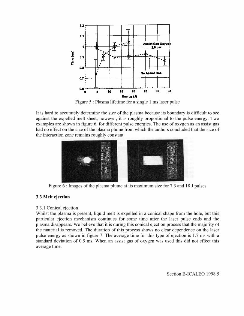
Figure 5 : Plasma lifetime for a single 1 ms laser pulse
It is hard to accurately determine the size of the plasma because its boundary is difficult to see against the expelled melt sheet, however, it is roughly proportional to the pulse energy. Two examples are shown in figure 6, for different pulse energies. The use of oxygen as an assist gas had no effect on the size of the plasma plume from which the authors concluded that the size of the interaction zone remains roughly constant.
Figure 6 : Images of the plasma plume at its maximum size for 7.3 and 18 J pulses
3.3 Melt ejection 3.3.1 Conical ejection Whilst the plasma is present, liquid melt is expelled in a conical shape from the hole, but this particular ejection mechanism continues for some time after the laser pulse ends and the plasma disappears. We believe that it is during this conical ejection process that the majority of the material is removed. The duration of this process shows no clear dependence on the laser pulse energy as shown in figure 7. The average time for this type of ejection is 1.7 ms with a standard deviation of 0.5 ms. When an assist gas of oxygen was used this did not effect this average time.
Section B-ICALEO 1998 5
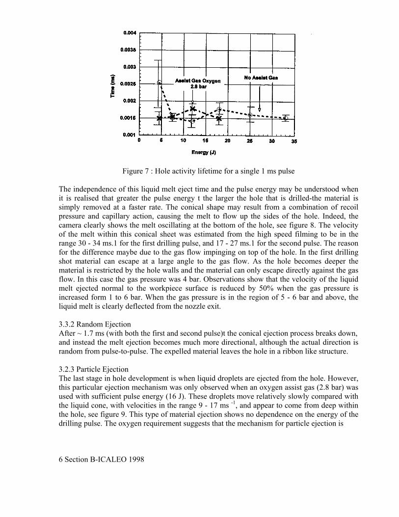
Figure 7 : Hole activity lifetime for a single 1 ms pulse
The independence of this liquid melt eject time and the pulse energy may be understood when it is realised that greater the pulse energy t the larger the hole that is drilled-the material is simply removed at a faster rate. The conical shape may result from a combination of recoil pressure and capillary action, causing the melt to flow up the sides of the hole. Indeed, the camera clearly shows the melt oscillating at the bottom of the hole, see figure 8. The velocity of the melt within this conical sheet was estimated from the high speed filming to be in the range 30 - 34 ms.1 for the first drilling pulse, and 17 - 27 ms.1 for the second pulse. The reason for the difference maybe due to the gas flow impinging on top of the hole. In the first drilling shot material can escape at a large angle to the gas flow. As the hole becomes deeper the material is restricted by the hole walls and the material can only escape directly against the gas flow. In this case the gas pressure was 4 bar. Observations show that the velocity of the liquid melt ejected normal to the workpiece surface is reduced by 50% when the gas pressure is increased form 1 to 6 bar. When the gas pressure is in the region of 5 - 6 bar and above, the liquid melt is clearly deflected from the nozzle exit. 3.3.2 Random Ejection After ~ 1.7 ms (with both the first and second pulse)t the conical ejection process breaks down, and instead the melt ejection becomes much more directional, although the actual direction is random from pulse-to-pulse. The expelled material leaves the hole in a ribbon like structure. 3.2.3 Particle Ejection The last stage in hole development is when liquid droplets are ejected from the hole. However, this particular ejection mechanism was only observed when an oxygen assist gas (2.8 bar) was used with sufficient pulse energy (16 J). These droplets move relatively slowly compared with the liquid cone, with velocities in the range 9 - 17 ms -1, and appear to come from deep within the hole, see figure 9. This type of material ejection shows no dependence on the energy of the drilling pulse. The oxygen requirement suggests that the mechanism for particle ejection is 6 Section B-ICALEO 1998

fuelled by an exothermic reaction. However, if the pressure is increased to ~ 5 bar, this particle emission appears to be suppressed, which may explain why better hole quality is obtained at lower gas pressures.
Figure 8: Images showing oscillation of liquid inside the hole, (a) 0.704 ms, (b) 0.741 ms, (c) 0.815 ms, (d) 0.926 ms, (e) 1.0 ms and (f) 1.07 ms after the start of the laser pulse. (a) (b) (c)
Figure 9: Images of particle ejection at 2.8 bar, 16 J, (a) 9.3 ms, (b) 10.04 ms, (c) 10.23 ms after the end of the laser pulse 3.3 Pulse Shaping The authors have previously undertaken a detailed study of percussion drilling involving factorial designed experiments. This demonstrated the importance of pulse shaping in the production of high quality holes. The high speed camera was therefore used to study the processes involved with different pulse shapes in more detail. Four different shapes were used, and these are summarised in table 1. The shapes are very different but in respect of energy and mean power they are very similar. The shapes were filmed at two different values of gas pressure, 1.2 and 6.0 bar. Two different focal positions were also used, + 1.0 mm and + 2.5 mm relative to the workpiece surface.
Section B-ICALEO 1998 7

Table 1 : Parameters for each different pulse shape
The camera was used to film the drilling events on-axis. Plasma formation was observed with pulse shapes 2, 3 and 4, having peak powers of 6.5, 4.0 and 4.0 kW respectively. Pulse 1, however, with its low peak power of 2 k W, did not produce a plasma. The lifetime of the plasma plume is plotted for the two different focal positions as a function of pulse shape in figure 10. The lifetime for pulse shape 2 is the combined time for each part of the pulse. For pulse shapes 2 and 3 the + 1 mm focal position produced more plasma than the + 2.5 mm. This is likely to result from the higher power density at the surface with the focus at + 1 mm. Pulse 4, however, showed the opposite effect, which may be due to the higher intensity at the end of the pulse interacting with the vaporised material above the hole. The gas pressure setting did not alter the plasma lifetime for either of the focal settings.
figure 10 : Plasma lifetime as a function of pulse shape
The liquid melt ejection times are plotted as a function of pulse shape in figure 11, for the two different focal positions. Pulse types 2, 3 and 4, though very different in shape have approximately the same melt ejection time. Pulse shape 1, however, having a low peak power and longer interaction time with the material has the longest melt time for both focal positions. From the video it is also possible to determine the breakthrough of the laser pulse. At the focal position of + 1 mm the number of shots to breakthrough was three for pulse shapes 1, 2 and 3, but 8 Section B-ICALEO 1998

pulse shape 4 breaks through on the second shot, corresponding to the highest drilling velocity. This maybe due to the initial heating of the material by the leading part of the pulse, which then allows for more efficient drilling by the second part. Pulse 4 also came out favourably in the factorial experimental design study which confirmed this pulse shape as best in terms of taper, hole roundness and hole variation. At the focal position of + 2.5 mm all pulses broke through on the third shot. The decrease in drilling efficiency for pulse shape 4 can possibly be explained by the increased plasma interaction discussed above, and vice versa for pulse shapes 1, 2 and 3.
Figure 11 : Liquid melt ejection time as a function of pulse shape and focal position From the on-axis high speed film, the basic drilling mechanism with each of the pulse shapes 1 - 3 appears almost identical, being similar to the mechanism with the single square pulse discussed earlier in detail (figure 3). Pulse shape 4, however, has a visibly different drilling mechanism. The initial coupling of the pulse into the surface appears to be more controlled than with the other pulse types. In the first half of the pulse (the 'pre-heat phase'), the growth of the hole is very uniform, and no plasma forms. It is in the second half of the pulse that most material is removed, however, during which time a plasma is excited. One problem that all of the pulse shapes suffer from, however, is that the material is not expelled in a uniform cone in the melt ejection part of hole development. The melt is instead ejected in one particular random direction, which is thought to affect the hole roundness. This may be due to instabilities in the gas flow, but there may be some contribution from a non-uniform energy distribution of the laser beam.
Section B-ICALEO 1998 9

4. Conclusions The laser percussion drilling mechanism in Nickel alloys with pulse energies of up to 30 J in 1 ms has been studied in this experiment. The process has been shown to consist of three stages: (i) Initial coupling of the laser into the surface, breaking down its reflectivity, and giving rise to
a plasma plume above the workpiece. This takes - 10 µs. (ii) Majority material removal: while the plasma plume is present, the material is generally
removed as a liquid in a well-defined 'cone', driven by the vapour pressure inside the hole. The plasma lifetime is typically the same as the pulse length, but this removal process continues for - 0.5 ms after the plasma has disappeared.
(iii) Continued hole development. The material removal continues, firstly as 'ribbons' of melt in random directions, and finally as droplets. These droplets are, however, only seen with an oxygen assist gas with a pressure in the range of 2 - 4 bar, indicating the importance of the assist gas flow and pressure in determining final hole quality. The hole reaches equilibrium after 31 - 70 ms depending on initial conditions.
Pulse shaping can improve hole quality, with the most successful being split into two parts, with the first half at relatively low power. During this part no plasma is produced, and only a small amount of material is removed. The majority of the material is instead removed during the second half of the pulse. It is thought that the preheat provided by the first half of the pulse provides a more controlled coupling into the material.
5. Acknowledgements The authors gratefully acknowledge the support of the Engineering & Physical Science Research Council, UK and Lumonics Ltd (Rugby, UK) 6. References [1] M. H. H van Dijk, G de Vlieger, J. E. Brouwer, Proc, 6th Int. Conf, Lasers in Manufacturing. Page 237-247 May 1989. ISBN 1-85423-047-6 [2] J. F .Ready Effects of High Power Laser Radiation Academic Press 1971 Page 101 Library of Congress Catalog Card Number 77-137597 [3] A. Ivarson, J. Powell, L. Ohlsson, C. Magnusson. Optimisation of the Laser Cutting Process for Thin Section Stainless Steels. ICALEO 1991 page 211. 10 Section B-ICALEO 1998