Investigation of the Corrugation in Foam Sheet … of the Corrugation in Foam Sheet ... show a wavy...
12
301 Cellular Polymers, Vol. 29, No. 5, 2010 © Smithers Rapra Technology, 2010 Investigation of the Corrugation in Foam Sheet Extrusion Walter Michaeli and Tilo Hildebrand* Institute of Plastics Processing at RWTH Aachen University (IKV), Seffenter Weg 201, 52074, Aachen, Germany ABSTRACT Extruded foam sheets of low densities in combination with a homogenous distribution of fine-celled bubbles show a wavy pattern transverse to the machine direction. This effect known as corrugation is systematically investigated in a long-term research project at the IKV. The aim of the project is to determine the process and foam parameters which lead to corrugation and thereafter develop strategies to minimise the corrugation in foam extrusion. In this paper, the research project is presented and first results of the investigations are discussed. INTRODUCTION Foam sheets made of polystyrene (PS), polypropylene (PP) and polyethylene (PE) with different thicknesses and densities are commonly used in the building and construction industries, for packaging and in the automotive sector (1,2) . In general, these products are manufactured in a foam extrusion process with physical blowing agents. As physical blowing agents, alkenes series, partially halogenated hydrocarbons and increasingly inert gases such as carbon dioxide (CO 2 ) and nitrogen (N 2 ) are used. However, for CO 2 and N 2 being the cheapest and environmentally friendliest blowing agents, the processing of these inert gases is combined with an extra effort. Due to their lack of solubility in most of the plastic melts, high process pressures are necessary to solve a sufficient amount of physical blowing agent in the melt. Furthermore CO 2 and N 2 show a higher coefficient of diffusion due to their low molecular size. In the foam extrusion process, an instant pressure drop in the extrusion die leads to an oversaturation of the physical blowing agent in the melt and initiates the nucleating phase in which tiny nuclei are formed. These nuclei continue *Tel:+49(0)2418028354;Fax:+49(0)2418022316; email: [email protected]
Transcript of Investigation of the Corrugation in Foam Sheet … of the Corrugation in Foam Sheet ... show a wavy...

301Cellular Polymers, Vol. 29, No. 5, 2010
Investigation of the Corrugation in Foam Sheet Extrusion
©Smithers Rapra Technology, 2010
Investigation of the Corrugation in Foam Sheet Extrusion
Walter Michaeli and Tilo Hildebrand*
Institute of Plastics Processing at RWTH Aachen University (IKV), Seffenter Weg 201, 52074, Aachen, Germany
ABSTRACT
Extruded foam sheets of low densities in combination with a homogenous distribution of fine-celled bubbles show a wavy pattern transverse to the machine direction. This effect known as corrugation is systematically investigated in a long-term research project at the IKV. The aim of the project is to determine the process and foam parameters which lead to corrugation and thereafter develop strategies to minimise the corrugation in foam extrusion. In this paper, the research project is presented and first results of the investigations are discussed.
INTRODUCTION
Foam sheets made of polystyrene (PS), polypropylene (PP) and polyethylene (PE) with different thicknesses and densities are commonly used in the building and construction industries, for packaging and in the automotive sector(1,2). In general, these products are manufactured in a foam extrusion process with physical blowing agents. As physical blowing agents, alkenes series, partially halogenated hydrocarbons and increasingly inert gases such as carbon dioxide (CO2) and nitrogen (N2) are used. However, for CO2 and N2 being the cheapest and environmentally friendliest blowing agents, the processing of these inert gases is combined with an extra effort. Due to their lack of solubility in most of the plastic melts, high process pressures are necessary to solve a sufficient amount of physical blowing agent in the melt. Furthermore CO2 and N2 show a higher coefficient of diffusion due to their low molecular size.
In the foam extrusion process, an instant pressure drop in the extrusion die leads to an oversaturation of the physical blowing agent in the melt and initiates the nucleating phase in which tiny nuclei are formed. These nuclei continue
*Tel: +49 (0)241 80 28354; Fax: +49 (0)241 80 22316; email: [email protected]
302 Cellular Polymers, Vol. 29, No. 5, 2010
Walter Michaeli and Tilo Hildebrand
their growth to cells by the diffusion of the physical blowing agent from the surrounding areas of nuclei and lead to the final foam structure. The speed of nucleating and cell growth is therefore highly dependent on the coefficient of diffusion. Having a rather high coefficient of diffusion in comparison to other physical blowing agents, CO2 as a blowing agent is quite difficult to handle due to the rapid foaming process.
Generally, the foaming process can be described as a three-dimensional growth of cells in a plastic melt. Especially for foamed sheets with low densities and a fine-celled foam structure, the expansion of the sheets is restricted by the edges which results in a wavy pattern transverse to the machine direction(3). Yet, the so-called corrugation has not been entirely investigated scientifically and is therefore subject in a current research project at the Institute of Plastics Processing (IKV).
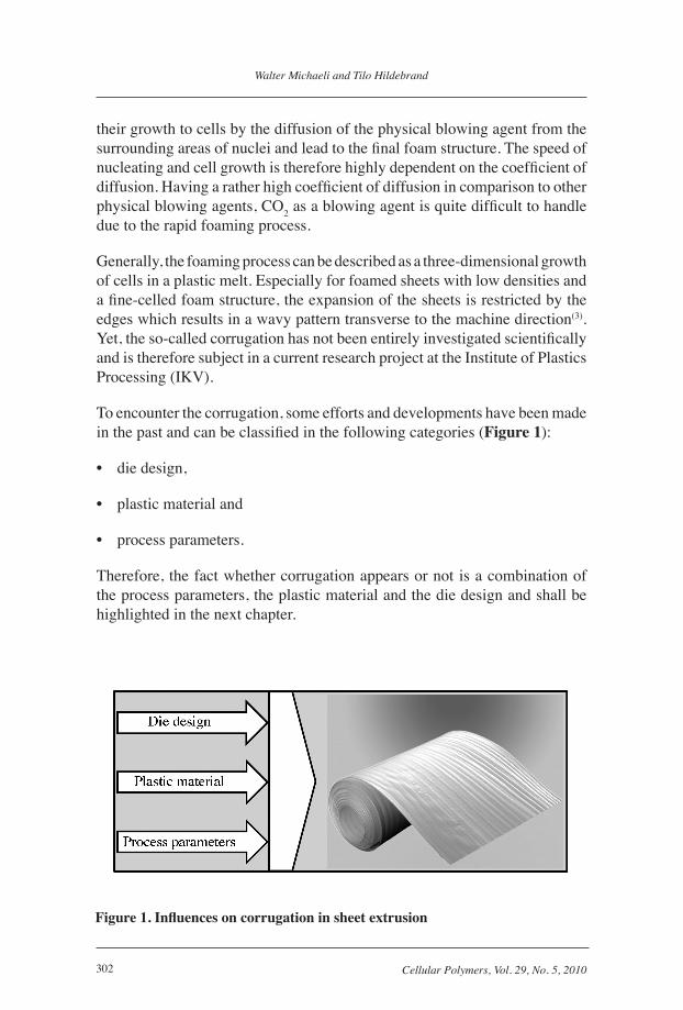
To encounter the corrugation, some efforts and developments have been made in the past and can be classified in the following categories (Figure 1):
• die design,
• plastic material and
• process parameters.
Therefore, the fact whether corrugation appears or not is a combination of the process parameters, the plastic material and the die design and shall be highlighted in the next chapter.
Figure 1. Influences on corrugation in sheet extrusion
303Cellular Polymers, Vol. 29, No. 5, 2010
Investigation of the Corrugation in Foam Sheet Extrusion
STRATEGIES TO REDUCE/ELIMINATE CORRUGATION IN FOAM SHEET EXTRUSION
Die Design
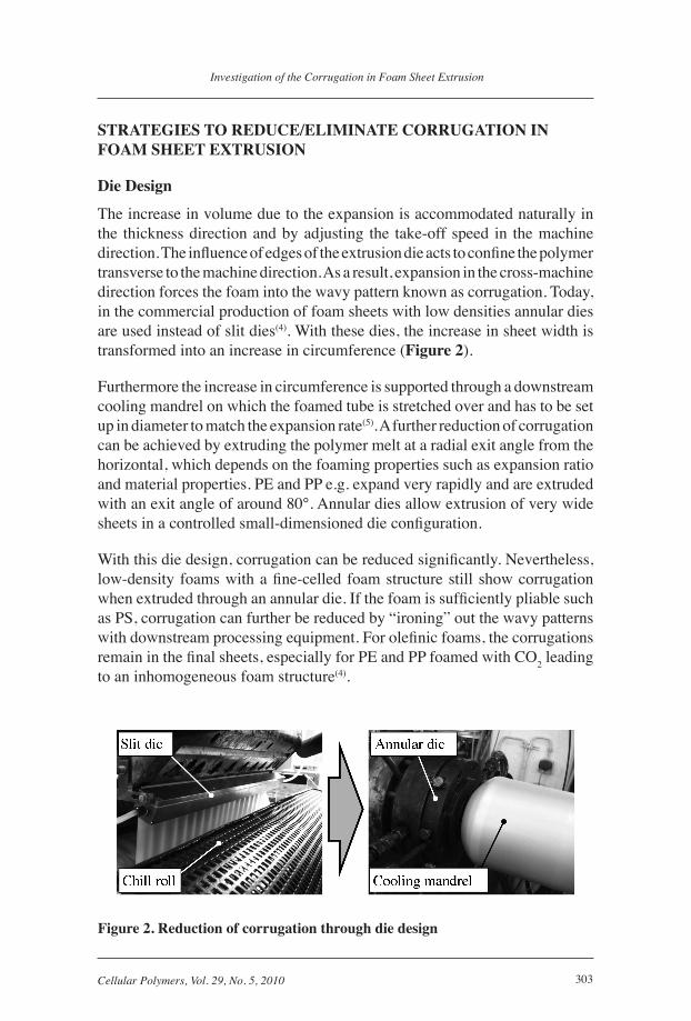
The increase in volume due to the expansion is accommodated naturally in the thickness direction and by adjusting the take-off speed in the machine direction. The influence of edges of the extrusion die acts to confine the polymer transverse to the machine direction. As a result, expansion in the cross-machine direction forces the foam into the wavy pattern known as corrugation. Today, in the commercial production of foam sheets with low densities annular dies are used instead of slit dies(4). With these dies, the increase in sheet width is transformed into an increase in circumference (Figure 2).
Furthermore the increase in circumference is supported through a downstream cooling mandrel on which the foamed tube is stretched over and has to be set up in diameter to match the expansion rate(5). A further reduction of corrugation can be achieved by extruding the polymer melt at a radial exit angle from the horizontal, which depends on the foaming properties such as expansion ratio and material properties. PE and PP e.g. expand very rapidly and are extruded with an exit angle of around 80°. Annular dies allow extrusion of very wide sheets in a controlled small-dimensioned die configuration.
With this die design, corrugation can be reduced significantly. Nevertheless, low-density foams with a fine-celled foam structure still show corrugation when extruded through an annular die. If the foam is sufficiently pliable such as PS, corrugation can further be reduced by “ironing” out the wavy patterns with downstream processing equipment. For olefinic foams, the corrugations remain in the final sheets, especially for PE and PP foamed with CO2 leading to an inhomogeneous foam structure(4).
Figure 2. Reduction of corrugation through die design

304 Cellular Polymers, Vol. 29, No. 5, 2010
Walter Michaeli and Tilo Hildebrand
PLASTIC MATERIAL
Another approach to reduce corrugation is the modification of the plastic material. Common commercial grades which are used for foam extrusion must have certain properties such as good melt strength and high melt viscosity. A fairly high viscosity of the melt is needed to achieve a stable foam structure as quick as possible after exiting the die. The high melt strength is required to prevent cell walls from rupture in the foaming process.
Sabic Europe B.V., Geleen, The Netherlands, developed a special ultra melt strength polyethylene (2202 UMS), which has the same MFR (2.0 g/10 min) and density as a commercial conventional foam grade (2102 TX00). The ultra melt strength material shows an increase in viscosity at processing temperatures, which results in a stiffer material that can avoid the appearance of corrugation (Figure 3).
The advantages of 2202 UMS over conventional LDPE grades having similar melt indices and densities are seen in the following disciplines(6):
• delayed foaming leading to better control of the expansion process
• higher melt strength leading to less corrugation
• better temperature resistance leading to less collapse
• wider operating window at the die
• better foaming. i.e., less gas dosing required to reach the same density
• smaller cell size which means savings on nucleating agent
• stiffer foams which means better strength properties
• no change in process ability, output as reference material
The advantages as far as corrugation is concerned are shown in Figure 4. The results were obtained on thin foam sheets in a density range of 150 - 300 kg/m3, foamed with CO2 as physical blowing agent under constant process parameters.
Process Parameters
Regarding the process parameters only few investigations have been published. Generally, it is mentioned that a low density combined with a fine-celled foam structure leads to corrugation. Especially with the use of CO2, corrugation appears due to the rapid and strong foaming behaviour. Less corrugation can be obtained with mixtures of CO2 with other physical blowing agents like pentane(7,8). Another approach is using mixtures of endothermic blowing agents

305Cellular Polymers, Vol. 29, No. 5, 2010
Investigation of the Corrugation in Foam Sheet Extrusion
Figure 3. Increase of viscosity through modified plastic material [Sabic Europe B.V.]
Figure 4. Reduction of corrugation through modified plastic material [Sabic Europe B.V.]
306 Cellular Polymers, Vol. 29, No. 5, 2010
Walter Michaeli and Tilo Hildebrand
and CO2 (9). These guidelines apply to foam extrusion of PS. For the extrusion
of PE or PP, no references could be found. Therefore, a research project was initiated to investigate the corrugation for PE foams foamed with CO2.
AIM AND SCOPE OF WORK OF THE RESEARCH PROJECT
The aim of the research project is to minimise corrugation in thermoplastic foam sheet extrusion. To achieve this aim, appropriate die exit angles, an adjusted application of cooling air and optimised process parameters are essential parts of the investigation.
The project is divided into three major steps. In the first step, the foaming behaviour is investigated using different nozzle diameters and varying the process parameters. As a result, knowledge about the speed of the foaming process is gained. Furthermore, the degree of foaming will be correlated with the process parameters and the physical blowing agent conversion factor will be determined. In the second step, foam sheets will be extruded with different recipes (percentage of nucleating agent and physical blowing agent) and different die pressures. Also, the influence of different radial exit angles and different mass flows of cooling air is part of the trials. In the third part of the project, the results of the first two steps are combined and an analytical model will be set up to predict corrugation.
In the next chapters, results of the first part of the research project are presented.
EXPERIMENTAL SETUP
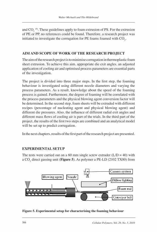
The tests were carried out on a 60 mm single screw extruder (L/D = 40) with a CO2 direct gassing unit (Figure 5). As polymer a PE-LD (2102 TX00) from
Figure 5. Experimental setup for characterising the foaming behaviour
307Cellular Polymers, Vol. 29, No. 5, 2010
Investigation of the Corrugation in Foam Sheet Extrusion
Sabic Europe B.V., Geleen, The Netherlands, and as nucleating agent an active nucleating agent (Hydrocerol CF40 E) from Clariant Masterbatches Deutschland GmbH was used. The throughput of the material was varied in two levels (10 kg/h and 15 kg/h). At the exit of the extruder, a nozzle was installed. The last part of the extrusion die was designed as an adapter which allows a quick change of nozzles with different diameters. For the trials, three different diameters were investigated (4, 5 and 6 mm). All nozzles have an angle of 0° in machine direction. An overview over the conducted trials is given in Table 1.
Table 1. Varied process parametersThroughput 10 kg/h 15 kg/hNozzle diameter 4 mm 5 mm 6 mmPhysical blowing agent (CO2) 0.6 wt.% 0.8 wt.% 1.0 wt.%Nucleating agent 0.3 wt.% 0.5 wt.% 0.7 wt.%
After the exit of the die, a conveyor belt with a Teflon finish has been placed to prevent the foamed rod from sagging under the influence of gravity. To observe the foaming behaviour, a camera system has been installed over the conveyor belt. Furthermore, a bright diffuse light source was mounted over the conveyor belt to be independent on the lighting situation and acquire images of repetitious accuracy.
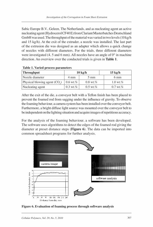
For the analysis of the foaming behaviour, a software has been developed. The software uses algorithms to detect the edges of the foamed rod giving the diameter at preset distance steps (Figure 6). The data can be imported into common spreadsheet programs for further analysis.
Figure 6. Evaluation of foaming process through software analysis
308 Cellular Polymers, Vol. 29, No. 5, 2010
Walter Michaeli and Tilo Hildebrand
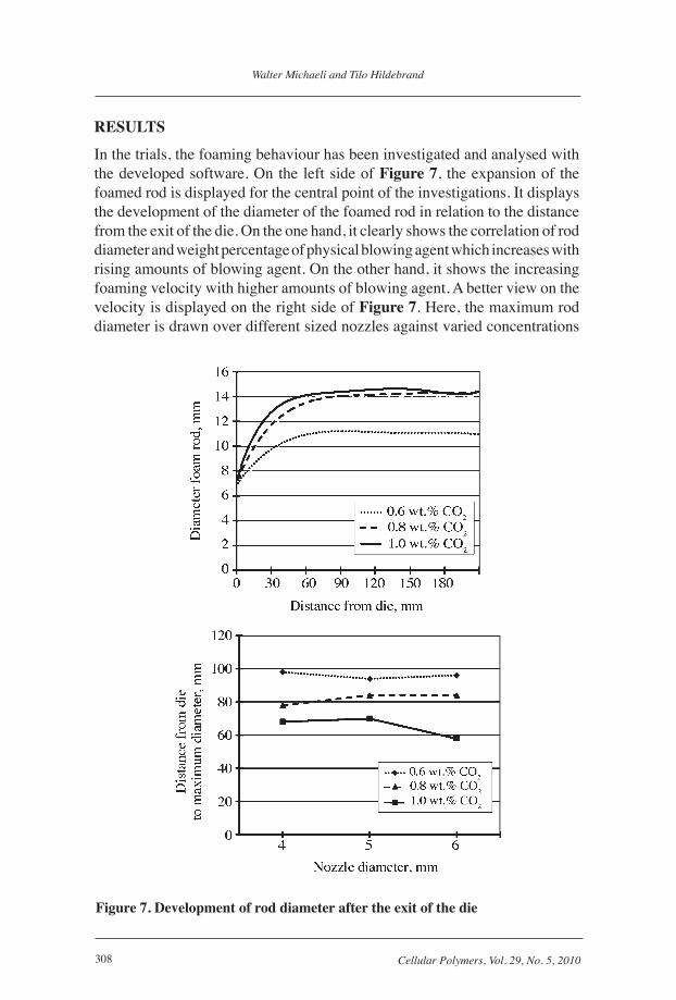
RESULTS
In the trials, the foaming behaviour has been investigated and analysed with the developed software. On the left side of Figure 7, the expansion of the foamed rod is displayed for the central point of the investigations. It displays the development of the diameter of the foamed rod in relation to the distance from the exit of the die. On the one hand, it clearly shows the correlation of rod diameter and weight percentage of physical blowing agent which increases with rising amounts of blowing agent. On the other hand, it shows the increasing foaming velocity with higher amounts of blowing agent. A better view on the velocity is displayed on the right side of Figure 7. Here, the maximum rod diameter is drawn over different sized nozzles against varied concentrations
Figure 7. Development of rod diameter after the exit of the die
309Cellular Polymers, Vol. 29, No. 5, 2010
Investigation of the Corrugation in Foam Sheet Extrusion
of blowing agents. The point of maximum diameter after the exit of the die is far more dependent on the concentration of blowing agent than the diameter of the nozzle.
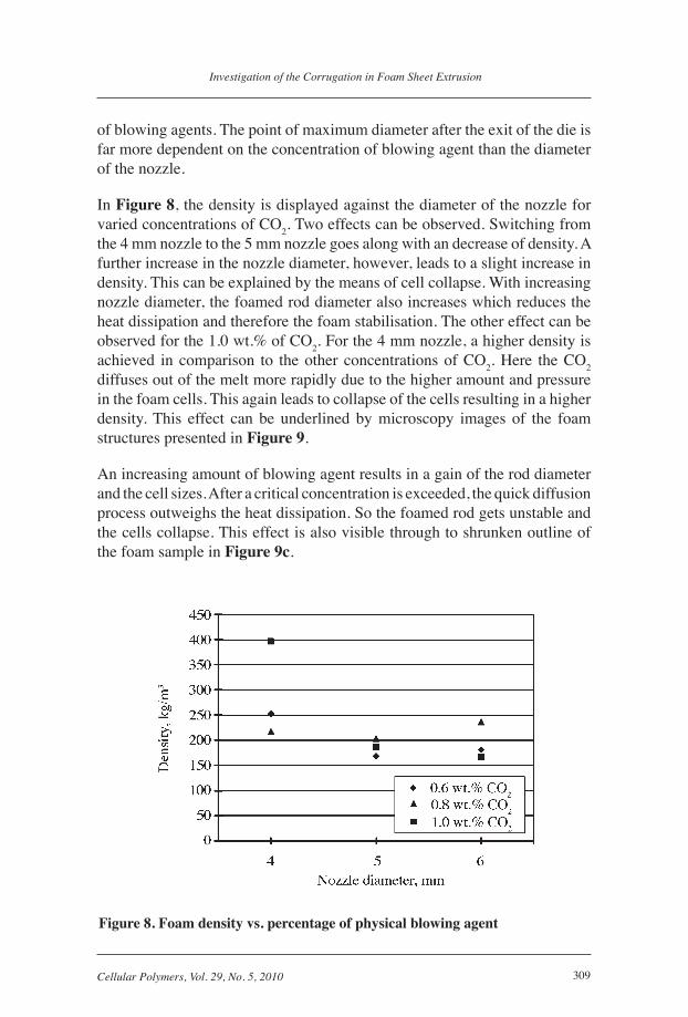
In Figure 8, the density is displayed against the diameter of the nozzle for varied concentrations of CO2. Two effects can be observed. Switching from the 4 mm nozzle to the 5 mm nozzle goes along with an decrease of density. A further increase in the nozzle diameter, however, leads to a slight increase in density. This can be explained by the means of cell collapse. With increasing nozzle diameter, the foamed rod diameter also increases which reduces the heat dissipation and therefore the foam stabilisation. The other effect can be observed for the 1.0 wt.% of CO2. For the 4 mm nozzle, a higher density is achieved in comparison to the other concentrations of CO2. Here the CO2 diffuses out of the melt more rapidly due to the higher amount and pressure in the foam cells. This again leads to collapse of the cells resulting in a higher density. This effect can be underlined by microscopy images of the foam structures presented in Figure 9.
An increasing amount of blowing agent results in a gain of the rod diameter and the cell sizes. After a critical concentration is exceeded, the quick diffusion process outweighs the heat dissipation. So the foamed rod gets unstable and the cells collapse. This effect is also visible through to shrunken outline of the foam sample in Figure 9c.
Figure 8. Foam density vs. percentage of physical blowing agent

310 Cellular Polymers, Vol. 29, No. 5, 2010
Walter Michaeli and Tilo Hildebrand
NEXT STEPS
In the next step, foam sheets will be extruded. Therefore, the process parameters of the first step are kept constant to assure comparability. As extrusion die, an annular die will be used. The foamed sheet will be automatically measured in thickness over the whole width. A special measuring device allows the detection of corrugations as shown in Figure 10.
As a conclusion, the results of the experiments are combined to develop a model that will predict the conditions leading to corrugation. This model can be used for die design and as a guideline for the right choice of process parameters. Since for other plastic materials different parameters are expected, the model will be tested for other materials and will be continuously extended.
Figure 9. Microscopy image of the foam structures for different blowing agent concentrations
Figure 10. Measured corrugation of PE foam sheets

311Cellular Polymers, Vol. 29, No. 5, 2010
Investigation of the Corrugation in Foam Sheet Extrusion
SUMMARY
In a current research project at the IKV, the effect of corrugation in thermoplastic foam sheet extrusion is examined. The main influences on corrugation and existing solutions to minimise corrugation have been listed. Thereafter, first results of the foaming behaviour of a common PE-LD type foamed with CO2 are presented. In the investigations, a new analysis system has been developed and established which allows a software analysis of the diameter of the foamed rod after exiting the die. It could be shown that with increasing amount of injected blowing agent, the distance from the die exit to the maximum diameter of the foamed rod decreases. Furthermore, a higher amount of blowing agent leads to an increase in diameter of the foamed rod. Considering the densities of the foamed rods, it could be shown that after a critical amount of blowing agent has been exceeded, an increase in the density is detected. This goes along with the analysis of the foam structure, which reveals smaller cell sizes for higher amounts of blowing agents and a shrunken outline of the foamed rod. Based on these elementary experiments further trials will be conducted.
ACKNOWLEDGMENTS
The research project No. 15767 N of the Forschungsvereinigung Kunststoffverarbeitung is sponsored as part of the “Industrielle Gemeinschaftsforschung” (IGF) by the German Bundesministerium für Wirtschaft und Technologie (BMWi) through the AiF, to whom we extend our thanks. We also gratefully acknowledge the support of Sabic Europe B.V. and Clariant Masterbatches GmbH for the donation of raw material for this investigation.
REFERENCES
1. Kropp D., Thermoplastische Schaumstoffe - Verarbeitungstechnik und Prozessanalyse, 5, Aachen Germany, (2003), Institut für Kunststoffverarbeitung (IKV).
2. Stadelbauer M., Thermoplastische Schaumstoffe - Verarbeitungstechnik und Möglichkeiten der Prozessanalyse, 4, Aachen, Germany, (2004), Institut für Kunststoffverarbeitung (IKV).
3. Sansone L.F., Foam Extrusion, Lancaster (PA), US, (2000).
4. Throne J.L., Thermoplastic foam extrusion, An introduction, Munich Germany, (2004).
312 Cellular Polymers, Vol. 29, No. 5, 2010
Walter Michaeli and Tilo Hildebrand
5. Breuer H., Plastverarbeiter 10 (1976), 539-545.
6. Krist J., Kunstoffschäume – Neues aus Spritzgießen und Extrusion, 5, Aachen, Germany, (2008), Institut für Kunststoffverarbeitung.
7. Shah B.H., US Patent 5,411,683, (1995).
8. Johnson D.E., Krutchen C.M., and Sharps V., US Patent 4,424,287, (1984).
9. Welsh G.C., Lee K.C., and Dalke D., US Patent 5,340,844 (1994).