INVESTIGATION OF GSM SIGNAL VARIATION DRY AND WET ...
11
Progress In Electromagnetics Research B, Vol. 1, 147–157, 2008 INVESTIGATION OF GSM SIGNAL VARIATION DRY AND WET EARTH EFFECTS S. Helhel, S ¸. ¨ Ozen, and H. G¨oksu Department of Electrical and Electronics Engineering Faculty of Engineering Akdeniz University Antalya, Turkey Abstract—This work proposes a site attenuation method to calculate the intensity of the field received by a mobile phone on a two-lane highway. To validate the model, radio propagation measurement was carried out through the intercity connection highway of the City of Isparta. The measurement system consisted of live radio base stations transmitting at 900 MHz and 1800 MHz. Downlink signal strength level data were collected by using TEMS test mobile phones, and were analyzed by TEMS Investigation, MapInfo and Google earth. Transmitted power-into-antenna was 14W for both 900MHz and 1800 MHz. Both base station sectors are facing towards the same direction having a 14dBi gain. A proposed approximation was compared with real data. The results indicate that wet white pine trees cause 3 dB to 6 dB extra loss at 1800 MHz and about 1 dB to 3 dB extra loss at 900 MHz. Although 1800 MHz transmitter is 10 m higher, it loses its advantage in signal strength at longer distances. 1. INTRODUCTION Signal quality and drop calls of mobile communication operators in buildings have been studied extensively for the last five years [1–6]. Helhel et al. [7, 8] proposed indoor ray tracing propagation model, and propagation through forest into the building model at previous studies, and showed that 1800MHz operators have disadvantage in comparison to 900 MHz operators. Teh et al. [9] studied a path- correction technique for modeling walls in a ray-tracing framework without increasing its complexity. The walls, earth in our sample, are treated as infinitesimally thin slabs in ray-tracing. Intercity connection ways as well as highways are important for GSM operators for site
Transcript of INVESTIGATION OF GSM SIGNAL VARIATION DRY AND WET ...

Progress In Electromagnetics Research B, Vol. 1, 147–157, 2008
INVESTIGATION OF GSM SIGNAL VARIATION DRYAND WET EARTH EFFECTS
S. Helhel, S. Ozen, and H. Goksu
Department of Electrical and Electronics EngineeringFaculty of EngineeringAkdeniz UniversityAntalya, Turkey
Abstract—This work proposes a site attenuation method to calculatethe intensity of the field received by a mobile phone on a two-lanehighway. To validate the model, radio propagation measurementwas carried out through the intercity connection highway of the Cityof Isparta. The measurement system consisted of live radio basestations transmitting at 900 MHz and 1800 MHz. Downlink signalstrength level data were collected by using TEMS test mobile phones,and were analyzed by TEMS Investigation, MapInfo and Googleearth. Transmitted power-into-antenna was 14 W for both 900 MHzand 1800 MHz. Both base station sectors are facing towards thesame direction having a 14 dBi gain. A proposed approximation wascompared with real data. The results indicate that wet white pinetrees cause 3 dB to 6 dB extra loss at 1800 MHz and about 1 dB to3 dB extra loss at 900 MHz. Although 1800 MHz transmitter is 10 mhigher, it loses its advantage in signal strength at longer distances.
1. INTRODUCTION
Signal quality and drop calls of mobile communication operators inbuildings have been studied extensively for the last five years [1–6].Helhel et al. [7, 8] proposed indoor ray tracing propagation model,and propagation through forest into the building model at previousstudies, and showed that 1800 MHz operators have disadvantage incomparison to 900 MHz operators. Teh et al. [9] studied a path-correction technique for modeling walls in a ray-tracing frameworkwithout increasing its complexity. The walls, earth in our sample, aretreated as infinitesimally thin slabs in ray-tracing. Intercity connectionways as well as highways are important for GSM operators for site

148 Helhel, Ozen, and Goksu
planning for competitive high quality service. This type of areais generally covered by one or two sites, and perfect planning maybring advantage to 1800 MHz operators when compared to 900 MHzoperators.
During latest studies, forest has been assumed to be ahomogeneous block attenuating the radio signal. The propagation ofradio waves over irregular surfaces is of great importance to designof fixed and mobile radio systems. The behavior of propagatingelectromagnetic waves through forests and thick woods has beenextensively studied in the last decade [10–14].
Cavalcante et al. [12] proposed a simple model using ray tracetechniques for mixed paths in forest environment. The model makesuse of diffraction and/or reflections on abrupt discontinuities caused bythe presence of a road inside the forest environment [15]. Cavalcanteet al. [12] utilized a small number of rays paths contributing to thereceived electromagnetic field, and shown that those analytical resultscan be described in terms of ray paths, which permit the calculationof mobile radio loss in a large class of forest environment.
Hsieh [15] proposed that dielectric constant of leaves (trees)depend on the dry mater fraction, and it almost independent offrequency at very high frequencies. Similar study was carried outby Helhel et al. [16] and similar results were obtained. The scopeof Georgiadou et al. [17] is the incorporation of rainfall rate effects onpulse propagation along Line-Of-Sight (LOS) Fixed Wireless Access(FWA) paths, and the applied model reveals higher distortion forshorter initial pulse widths, higher rainfall rates and longer paths ofpropagation.
These results say that dielectric properties of trees vary by seasons,and depending on their saline water of leaves. Rogers et al. [18]reported a static single white pine attenuation as 10.6 dB in the averageand 12.1 dB at maximum, and the attenuation coefficient as 1.2 dB/min the average and 1.5 dB/m at maximum at 900 MHz using circularlypolarized antennas. From the same study it can be concluded thatattenuation coefficient is 2 dB/m in the average at 1800 MHz. Li et al.[19] proposed an analytical expression in which equivalent permittivityfor rain medium is presented by utilizing system identification toinvestigate the electromagnetic wave attenuation induced by rain.Their results show that the permittivity is a function of both thefrequency and the rain rate.
In this study, an approximation of site attenuation approachhas been used for calculating propagation loss, and compared withreal data obtained at both 900 MHz and 1800 MHz on the highways.Wetness of earth (tree) effects on radio propagation and penetration

Progress In Electromagnetics Research B, Vol. 1, 2008 149
loss capabilities of single line trees have also been analyzed anddiscussed.
2. MEASUREMENT SETUP AND GEOMETRY
Measurements were made by using Ericsson K600i at 1800 MHz, andEricsson T610 at 900 MHz. Both mobile phones were loaded byEricsson test software. Normalized received signal power given byMartijin et al. [20] was measured. RxLev and Pr are defined asthe measured average received signal level, and received signal levelgiven by Eq. (1) that the propagation loss (Lp) between receiving andtransmitting antennas was calculated by using Eq. (2), where Pt isthe transmitted power. The accuracy of TEMS telephone measuredRxLev is ± 1 dB, and the received signal measurement range is from0 dBm to 110 dBm, where 110 dBm is the noise floor. Pr is theaverage received signal power measured within one slow associatedcontrol channel (SACCH) multi-frame of approximately 480 ms. Intotal approximately 100 samples are taken within one SACCH multi-frame [20]. Car speed was maintained at 40 km/h for collecting enoughnumbers of SACH frames.
RxLev = Pr (dBm) + 110 dB (1)Lp = Pt − RxLev (2)
Intercity has two directions that each direction has 15 m wideand 5 m apart from each other as shown in Fig. 1(a) and Fig. 1(b).South-North direction has been assumed as no obstructed, as wellas north-south direction is single line white pine obstructed. In thisstudy, 900 MHz transmitter antennas are mounted at the top of 20 mheight tower as well as 1800 MHz antennas are mounted at the topof 30 m tower. Both 900 MHz and 1800 MHz antennas have sameelectrical down tilt of 6 degree, 14 dBi antenna gain, and same powerinto antenna values of 14 W.
3. FORMULATION OF THE PROBLEM
Received signal strength level by mobile phone is the vector summationof plane waves originated from main source and secondary sourceswhich is described as Huygens principles [21]. Geometry of datacollection area is demonstrated by Fig. 1.

150 Helhel, Ozen, and Goksu
(a)
(b)
Figure 1. Drive-Test/model area view. (a) View of intercity road.(b) Collected data presentation on Google earth map.
3.1. Ground Reflection Contribution
An LOS path may have adequate Fresnel zone clearance, and yet stillhave a path loss which differs significantly from free space under normalrefraction conditions. In paths over relatively smooth ground or bodiesof water, however, ground reflections can be a major determinant ofpath loss. In a radio path consisting of a direct path plus a ground-reflected path, the path loss depends on the relative amplitude andphase relationship of the signals propagated by the two paths. Inextreme cases, where the ground reflected path has Fresnel clearance
Progress In Electromagnetics Research B, Vol. 1, 2008 151
and suffers little loss from the reflection itself (or attenuation fromtrees, etc.), then its amplitude may approach that of the direct path.Then, depending on the relative phase shift of the two paths, onemay have an enhancement of up to 6 dB over the direct path alone,or cancellation resulting in additional path loss of 20 dB or more.The amplitude and phase of the reflected wave depend on a numberof variables, including conductivity and permittivity of the reflectingsurface, frequency, angle of incidence, and polarization.
Beroual et al. [22] studied and analyzed concrete materials forassessment of cavities and water contents in it, water contaminationaffects on dielectric materials has also been reported by Helhel etal. [16], previously. They have reported that real part of dielectricpermittivity varies between from 7 to 35 (εr = [7−35]), and imaginarypart of it varies between 0.2 to 3 (ε′′r = [0.2 − 3]) with respect towater content between 0% to 50%. Throughout this study, sincethe experiments were carried out on asphalt/concrete mixed roads,these dielectric coefficients have been selected for ground reflectioncalculations.
3.2. (No) Diffraction Contribution
At west side of intercity road, which is assumed as without obstructedzone, it has to be checked that a diffracted contribution is either thereor not. A Fresnel zone is a simpler concept to understand a diffractionaffect: it is the volume of space enclosed by an ellipsoid, which has thetwo antennas at the ends of a radio link at its foci. The two-dimensionalrepresentation of a Fresnel zone is shown in Fig. 1. For the first Fresnelzone, n = 1 and the path length differs by l/2 (i.e., a 180◦ phase reversalwith respect to the direct path). For practical purposes, only the firstFresnel zone need be considered for calculation. A radio path hasfirst Fresnel zone clearance if no objects capable of causing significantdiffraction penetrate the corresponding ellipsoid. This means thatgeometry can be assumed as with no diffraction contribution in thecase of having 60% of the first Fresnel clearance.
For first Fresnel zone clearance, the distance h from the nearestpoint of the obstacle to the direct path must be at least as in Eq. (3),where f in GHz, d1 and d2 are in km, and h in meters [23].
h = 17.3
√d1 · d2
f(d1 + d2)(3)
For this problem, since d1 � d2 square root term goes to ≈√
1/fand h ≈ 18 m for 900 MHz and 14 m for 1800 MHz. A clearance of

152 Helhel, Ozen, and Goksu
8 m is about 55% of 900 MHz and 45% of 1800 MHz, so it is sufficientto allow negligible diffraction loss. Finally, received electric field canbe described as a combination of direct wave propagation and groundreflected wave propagation given below as in Eq. (4) [24, 25]. Whilethe measurements have been carried out behind the tree, a penetrationloss of white pine of 10 dB was added to the final loss calculation
Emaxr =
√49.2
[r22+r2
1 · |ρh|2+r2 · r1 · |ρh| cos (φh−β [r2−r1])]1/2
r1 · r2(4)
where
r1 =√
R2 + (ht − 1.5)2
r2 =√
R2 + (ht + 1.5)2
ρh =sin γ − (K − j60λσ − cos2 γ)1/2
sin γ + (K − j60λσ − cos2 γ)1/2
(5)
K is the relative dielectric constantσ conductivity, in Siemens/meterγ angle of incidenceλ wavelength, in meters.
Power equivalent of this electric field can be expressed by usingEq. (5) [24, 25]
Pr =|Er|2
30 · G1(θ)·∣∣∣∣ l
e−jkl
∣∣∣∣2
(6)
where Pr is the received signal power which is also given at Eq. (1),G1(θ) is the directed antenna gain and l is the total propagation pathlength in meter. Finally path loss can be calculated by using Eq. (6),Eq. (1) and Eq. (2) by using electric field calculation.
4. MEASUREMENTS AND PREDICTIONS
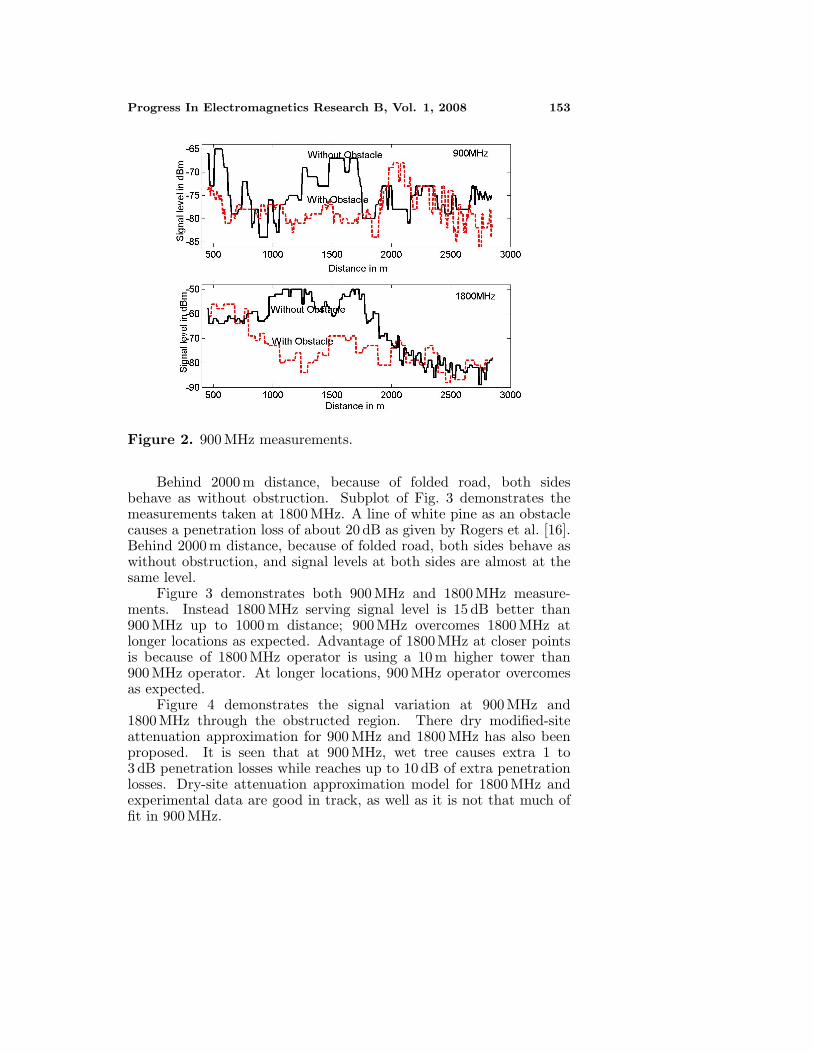
Figure 2 demonstrates the measurements taken at 900 MHz. A line ofwhite pine as an obstacle causes a penetration loss of 10 dB to 15 dBas given by Rogers et al. [18]. As seen from the figures that between750 m and 1000 m, signal at both sides are almost at the same level.It is because of wider gabs between trees which area is reserved forfurther crossing roads.
Progress In Electromagnetics Research B, Vol. 1, 2008 153
Figure 2. 900 MHz measurements.
Behind 2000 m distance, because of folded road, both sidesbehave as without obstruction. Subplot of Fig. 3 demonstrates themeasurements taken at 1800 MHz. A line of white pine as an obstaclecauses a penetration loss of about 20 dB as given by Rogers et al. [16].Behind 2000 m distance, because of folded road, both sides behave aswithout obstruction, and signal levels at both sides are almost at thesame level.
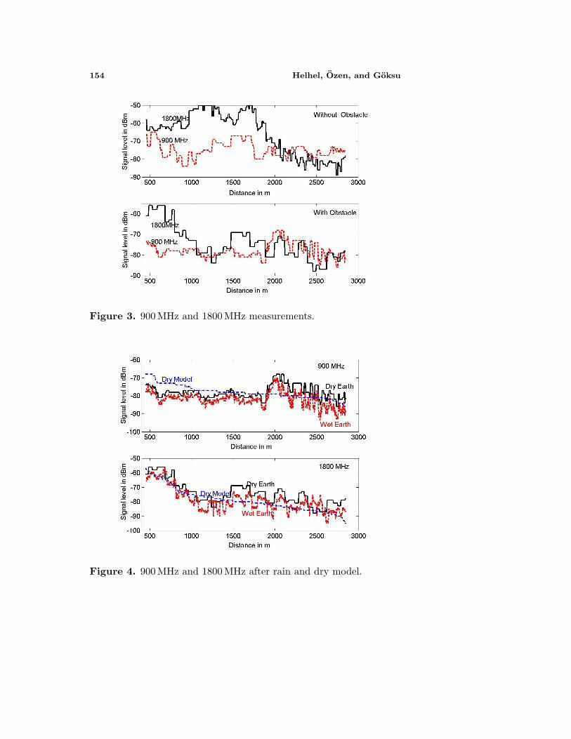
Figure 3 demonstrates both 900 MHz and 1800 MHz measure-ments. Instead 1800 MHz serving signal level is 15 dB better than900 MHz up to 1000 m distance; 900 MHz overcomes 1800 MHz atlonger locations as expected. Advantage of 1800 MHz at closer pointsis because of 1800 MHz operator is using a 10 m higher tower than900 MHz operator. At longer locations, 900 MHz operator overcomesas expected.
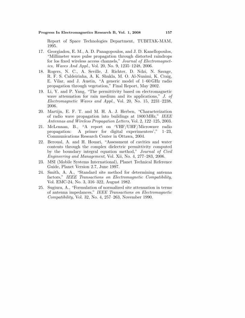
Figure 4 demonstrates the signal variation at 900 MHz and1800 MHz through the obstructed region. There dry modified-siteattenuation approximation for 900 MHz and 1800 MHz has also beenproposed. It is seen that at 900 MHz, wet tree causes extra 1 to3 dB penetration losses while reaches up to 10 dB of extra penetrationlosses. Dry-site attenuation approximation model for 1800 MHz andexperimental data are good in track, as well as it is not that much offit in 900 MHz.
154 Helhel, Ozen, and Goksu
Figure 3. 900 MHz and 1800 MHz measurements.
Figure 4. 900 MHz and 1800 MHz after rain and dry model.

Progress In Electromagnetics Research B, Vol. 1, 2008 155
5. CONCLUSION
Dry earth measurements say that white pine has a penetration losscapability of 5 dB to 10 dB at 900 MHz and 10 dB to 25 dB for1800 MHz. higher penetration loss regions are the locations where twolines of white pines are present.
Comparison of 900 MHz and 1800 MHz from Fig. 4, at both sidesof intercity road, gives us that at longer distances 900 MHz signal levelbecomes stronger then 1800 MHz even 1800 Hz is transmitting fromhigher tower. Subplot of Fig. 4 shows that in the case of obstructionhigher frequency (1800 MHz) loose it is energy sharper then lowerfrequency (900 MHz).
Figure 4 gives us a conclusion about the effect of wet earthon radio propagation. Increased earth conductivity with heavy rainwas assumed that ground reflection contribution would have beenincreased, but it is not! Actually, this expectation was true, but wettree caused extra penetration loss is bigger than extra earth reflectiongain. This is because that wet earth effect with wet tree obstructiongives us extra losses instead of extra gain.
For a big conferences, big organizations and national days;planners are asked to design a “mobile base station” for a period ofweek or weeks. These results show us that especially for winter times,meteorological data has to be taken into account for such a temporarysite design.
ACKNOWLEDGMENT
I would like to thank to Akdeniz University, Science Research ProjectSupport Unit (BAPYB), and Vodafone Telecommunication for theirtechnical support.
REFERENCES
1. Helhel, S., E. Karacuha, and S. Seker, “Ray tracing propagationmodel Of UHF radio waves for corridors,” Icecs’97, Cairo, Egypt,December 15–18, 1997.
2. Yamauchi, Y., T. Abe, and T. Sekiguchi, “Experimental studyof radio propagation characteristics in an underground street andcorridors,” Proc. of EMC, Vol. EMC-28, No. 3, August 1986.
3. Emsline, A. G., R. L. Lagace, and P. F. Strong, “Theory of thepropagation Of UHF radio waves in coal mine tunnels,” IEEETrans. on Antennas and Propagation, Vol. AP-23, No. 2, March1975.

156 Helhel, Ozen, and Goksu
4. Tan, S. Y. and H. S. Tan, “UTD propagation model in an urbanstreet scene for microcellular Comm.,” Trans. on Emc, Vol. 35,No. 4, November 1993.
5. Hata, M., “Empirical formula for propagation loss in land mobileradio services,” IEEE Transactions on Vehicular Technologies,Vol. VT-29, No. 3, 317–325, August 1980.
6. Martijn, E. F. T. and M. H. A. J. Herben, “Characterizationof radio wave propagation into buildings at 1800 MHz,” IEEEAntennas and Wireless Propagation Letters, Vol. 2, 122–125, 2003.
7. Helhel, S. and S. Ozen, “Disadvantage of 1800 MHz operatorsin roaming competition in an airport welcome lobby,” Workshopon Electromagnetic Wave Scattering EWS 2006, Gebze, Turkey,2006.
8. Helhel, S., “Comparison of 900 MHz and 1800 MHz indoorpropagation deterioration,” IEEE Transactions on AntennaPropagation, Vol. 54, No. 12, 3921–3924, December 2006.
9. Teh, C. H., F. Kung, and H. T. Chuah, “A path-corrected wallmodel for ray-tracing propagation modeling,” J. of Electromagn.Waves and Appl., Vol. 20, No. 2, 207–214, 2006.
10. Tamir, T., “Radio wave propagation along mixed paths inforest environments,” IEEE Trans. on Antennas and Propagation,Vol. AP-25, No. 4, 471–477, July 1977.
11. Cavalcante, G. P. S. and A. J. Giarola, “Optimization of radio-communication in three layered media,” IEEE Transactions onAntennas and Propagation, Vol. 31, No. 1, 1983.
12. Cavalcante, G. P. S., D. A. Rogers, and A. J. Giarola, “Radio lossin forest using a model with four layered media,” Radio Science,Vol. 18, No. 5, 1983.
13. Cavalcante, G. P. S., M. A. R. Sanches, and R. A. N. Oliveira,“Mobile radio propagation along mixed paths in forest environ-ment,” Journal of Microwaves and Optoelectronics, Vol. 1, No. 4,42–52, September 1999.
14. Oliveira, R. A. N., G. P. S. Cavalcante, and G. L. Siqueira, “Raytracing model for mobile systems in a forested environments,”ITS’98 International Telecommunication Symposium, 206–311,Sao Paulo, Basil, Aug. 1998.
15. Hsieh, C.-Y., “Dependence of backscattering from leaves on dry-matter fraction and permittivity of saline water of leaves,” Journalof Microwaves and Optoelectronics, Vol. 3, No. 3, December 2003.
16. Helhel, S., B. COlak, D. A. Sahinkaya, and H. Serbest, “Drymatter fraction affect on backscattering at 8–12 GHz,” Spring
Progress In Electromagnetics Research B, Vol. 1, 2008 157
Report of Space Technologies Department, TUBITAK-MAM,1995.
17. Georgiadou, E. M., A. D. Panagopoulos, and J. D. Kanellopoulos,“Millimeter wave pulse propagation through distorted raindropsfor los fixed wireless access channels,” Journal of Electromagnet-ics, Waves And Appl., Vol. 20, No. 9, 1235–1248, 2006.
18. Rogers, N. C., A. Seville, J. Richter, D. Ndzi, N. Savage,R. F. S. Caldeirinha, A. K. Shukla, M. O. Al-Nuaimi, K. Craig,E. Vilar, and J. Austin, “A generic model of 1–60 GHz radiopropagation through vegetation,” Final Report, May 2002.
19. Li, Y. and P. Yang, “The permittivity based on electromagneticwave attenuation for rain medium and its applications,” J. ofElectromagnetic Waves and Appl., Vol. 20, No. 15, 2231–2238,2006.
20. Martijn, E. F. T. and M. H. A. J. Herben, “Characterizationof radio wave propagation into buildings at 1800 MHz,” IEEEAntennas and Wireless Propagation Letters, Vol. 2, 122–125, 2003.
21. McLennan, B., “A report on ‘VHF/UHF/Microwave radiopropagation: A primer for digital experimenters’,” 1–23,Communications Research Center in Ottawa, 2004.
22. Beroual, A. and H. Houari, “Assessment of cavities and watercontents through the complex dielectric permittivity computedby the boundary integral equation method,” Journal of CivilEngineering and Management, Vol. Xii, No. 4, 277–283, 2006.
23. MSI (Mobile Systems International), Planet Technical ReferenceGuide, Planet Version 2.7, June 1997.
24. Smith, A. A., “Standard site method for determining antennafactors,” IEEE Transactions on Electromagnetic Compatibility,Vol. EMC-24, No. 3, 316–322, August 1982.
25. Sugiura, A., “Formulation of normalized site attenuation in termsof antenna impedances,” IEEE Transactions on ElectromagneticCompatibility, Vol. 32, No. 4, 257–263, November 1990.