Investigation into Bluetooth...
81
PARREND Jean 2004/2005 B.Eng in Computer and Communications Engineering Person ID: 246275 E-mail: [email protected] Liverpool John Moores University School of Engineering BEng final year project in Computer and Communications Engineering ENRCF1100 Investigation into Bluetooth Technology Supervisor: T A Moore Room 519 Tel: 2171 [email protected]
Transcript of Investigation into Bluetooth...
PARREND Jean 2004/2005 B.Eng in Computer and Communications Engineering Person ID: 246275 E-mail: [email protected]
Liverpool John Moores University School of Engineering
BEng final year project in Computer and Communications Engineering ENRCF1100
Investigation into Bluetooth Technology
Supervisor: T A Moore Room 519 Tel: 2171 [email protected]

Jean Parrend BEng Computer & Communications Engineering
Investigation into Bluetooth technology 2
ABSTRACT
This final year project report describes precisely the technical specifications of the Bluetooth
technology, i.e. the architecture of a chip and its capabilities. It especially focuses on “core”
protocols, such as Radio Frequency, Baseband, Link Manager Protocol, Host Controller
Interface, Logical Link Control and Adaptation Protocol, Service Discovery Protocol, and
adopted protocols, such as PPP, TCP/UDP/IP or WAP. Bluetooth profiles and usage models,
such as Generic Access, Headset, LAN Access or File Transfer are describe too, without
avoiding security problems and competing technologies. It also presents a series of material
tests, which appears in the second part.

Jean Parrend BEng Computer & Communications Engineering
Investigation into Bluetooth technology 3
Table of contents Glossary of symbols used ……………………………………………………………………..6 Introduction…………………………………………………………………………………….9
A) Presentation of Bluetooth Technology………………………………..10 1. Basics…………………………………………………………………………………….. 10 2. Architecture……………………………………………………………………………...11
2.1. General description…………………………………………………………..............11 2.2. Protocol stack………………………………………………………………………...13
3. Core protocols…………………………………………………………………………...14
3.1. RF : The radio layer………………………………………………………………...14 3.1.1. Frequency band and channel arrangement……………………………………14 3.1.2. Transmitter characteristics………………………………………………..…..14
3.1.2.1.Modulation characteristics…………………………………………..……16 3.1.3. Receiver characteristics…………………………………………………..…...16
3.1.3.1. Actual sensitivity level……………………………………………..…….17 3.1.3.2. Interference performance……………………………………………..….17 3.1.3.3. Out-of-band blocking………………………………………………….....17 3.1.3.4. Maximum usable level…………………………………………………...18 3.1.3.5. Receiver signal strength indicator………………………………………..18
3.2. Baseband……………………………………………..……………………………..18 3.2.1. General description……………………………..…………………………….18 3.2.2. Clock……………………………………………..…………………………...20 3.2.3. Device addressing……………………………….……………………………22 3.2.4. Access codes…………………………………….……………………………22 3.2.5. Physical channels……………………………….…………………………….23
3.2.5.1. Physical channel definition………………….…………………………...24 3.2.5.2. Hop selection………………………………….…………………………24
3.2.6. Physical links……………………………………….………………………...25 3.2.7. Logical transports…………………………………….………………………26
3.2.7.1. Synchronous logical transport…………………….……………………..27 3.2.7.2. Asynchronous logical transport…………………….……………………27 3.2.7.3. Active slave broadcast transport…………………….…………………...28 3.2.7.4. Parked slave broadcast transport……………………..………………….28
3.2.8. Logical links……………………………………………….…………………28 3.2.8.1. Link Control logical link (LC)……………………….…………………..29 3.2.8.2. ACL-Control logical link (ACL-C)……………………………………...29 3.2.8.3. User asynchronous/isochronous logical link (ACL-U)………………….29 3.2.8.4. User synchronous data logical link (SCO-S)………………………….....29 3.2.8.5. User extended synchronous data logical link (eSCO-S)…………………30 3.2.8.6. Logical link properties………………………………………..………….30
3.2.9. Packets………………………………………………………………………..30 3.2.9.1.General formats…………………………………………………………..30

Jean Parrend BEng Computer & Communications Engineering
Investigation into Bluetooth technology 4
3.2.9.2. Bit ordering……………………………………………………………....31 3.2.9.3. Access code……………………………………………………………....31 3.2.9.4. Packet header…………………………………………………………….32
3.2.9.4.1. Packet types………………………………………………………32 3.2.9.5. Payload format…………………………………………………………...33 3.2.9.6.Packet summary…………………………………………………………..33
3.2.10. Bitstream processing………………………………………………………….35 3.2.11. States / Modes………………………………………………………………...35
3.2.11.1. Overview of states…………………………………………………….35 3.2.11.2. Standby state…………………………………………………………..36 3.2.11.3. Connection State………………………………………………………36
3.2.11.3.1. Active mode………………………………………………………37 3.2.11.3.2. Sniff mode………………………………………………………...38 3.2.11.3.3. Hold mode………………………………………………………...38
3.2.11.4. Park state………………………………………………………………39 3.3. LMP………………………………………………………………………………...40
3.3.1. General aspects……………………………………………………………….40 3.3.2. Message transport…………………………………………………………….41 3.3.3. Synchronization………………………………………………………………41 3.3.4. Packet format…………………………………………………………………42 3.3.5. Transactions…………………………………………………………………..43 3.3.6. Error handling………………………………………………………………...44
3.4. HCI…………………………………………………………………………………44 3.4.1. Overview of host controller transport layer…………………………………..45 3.4.2. Overview of commands et events…………………………………………….45 3.4.3. HCI flow control……………………………………………………………...46 3.4.4. HCI formats…………………………………………………………………...46
3.5. L2CAP……………………………………………………………………………...46 3.5.1. General aspects……………………………………………………………….47 3.5.2. L2CAP features……………………………………………………………….47
3.6. SDP…………………………………………………………………………………50 3.6.1. General description…………………………………………………………...50
3.6.1.1.Motivation………………………………………………………………...50 3.6.1.2. SDP features……………………………………………………………...50 3.6.1.3. Deferred features…………………………………………………………51
3.6.2. Overview……………………………………………………………………...52 3.6.2.1. SDP client-server interaction…………………………………………….52 3.6.2.2. Service record……………………………………………………………54 3.6.2.3. Searching for services……………………………………………………54 3.6.2.4. Browsing for services…………………………………………………….54
4. Cable replacement protocol and telephony……………………………………………56
4.1. RFCOMM……………………………………………………………………………56 4.2. TCS…………………………………………………………………………………..56
5. Adopted protocols……………………………………………………………………….57
5.1. PPP………………………………………………………………………………….57 5.2. TCP/UDP/IP………………………………………………………………………...57 5.3. OBEX……………………………………………………………………………….57 5.4. WAP………………………………………………………………………………...58

Jean Parrend BEng Computer & Communications Engineering
Investigation into Bluetooth technology 5
6. Profile specifications and usage models………………………………………………..59 6.1. The profiles…………………………………………………………………………59
6.1.1. Generic Access………………………………………………………………..59 6.1.2. Service Discovery Application……………………………………………….59 6.1.3. Serial Port……………………………………………………………………..60 6.1.4. Generic Object Exchange……………………………………………………..60 6.1.5. Cordless Telephone…………………………………………………………...60 6.1.6. Intercom………………………………………………………………………60 6.1.7. Headset………………………………………………………………………..60 6.1.8. Fax…………………………………………………………………………….61 6.1.9. Dial-Up Networking………………………………………………………….61 6.1.10. LAN Access…………………………………………………………………..61 6.1.11. Object Push…………………………………………………………………...61 6.1.12. File Transfer…………………………………………………………………..61 6.1.13. Synchronization………………………………………………………………62 6.1.14. Additional profiles……………………………………………………………62
6.2. The usage models…………………………………………………………………..63 6.2.1. Internet bridge………………………………………………………………...63 6.2.2. 3-in-1 phone…………………………………………………………………..64 6.2.3. Ultimate headset………………………………………………………………64 6.2.4. LAN access…………………………………………………………………...64 6.2.5. File transfer…………………………………………………………………...65 6.2.6. Synchronization………………………………………………………………65
7. Establishing connections in Bluetooth…………………………………………………67 8. Security……………………………………………………………………………...…...69
8.1. Security methods……………………………………………………………………..69 8.2. Device trust levels……………………………………………………………………69 8.3. Security level of services…………………………………………………………….70
9. Competing technologies…………………………………………………………………71
9.1. Positioning wireless technologies…………………………………………………...71 9.2. Wireless competing technologies…………………………………………………...72
9.2.1. IrDA…………………………………………………………………………..72 9.2.2. Wi-Fi………………………………………………………………………….72
9.3. Wireless technologies : advantages and disadvantages……………………………..72 9.3.1. Bluetooth……………………………………………………………………...72 9.3.2. Wi-Fi………………………………………………………………………….73 9.3.3. IrDA…………………………………………………………………………..73
9.4. Comparing wireless technologies…………………………………………………...74
B) Test of Bluetooth devices………………………………………………75 Discussion and conclusion……………………………………………………………………77 Reference and bibliography…………………………………………………………………..78 Appendix……………………………………………………………………………………...79

Jean Parrend BEng Computer & Communications Engineering
Investigation into Blutetooth Technology 6
GLOSSARY OF SYMBOLS USED
A Access Code : Each baseband packet starts with an Access code. ACL : Asynchronous Connection-oriented link Active Mode : In the active mode, the Bluetooth unit actively participates on the channel. Authentication : The process of verifying 'who' is at the other end of the link. B Baseband : The baseband describes the specifications of the digital signal processing part of the hardware. BD_ADDR : Bluetooth Device Address. Each Bluetooth transceiver is allocated a unique 48-bit device address. BER : Bit Error Rate. C CAC : Channel Access Code. CLK : Clock, typically the master device clock which defines the timing used in the piconet. CLKE : Clock Estimate, a slave's estimate of the master's clock, used to synchronise the slave device to the master. CLKN : Clock Native, the clock of the current Bluetooth Device. CRC : Cyclic Redundancy Check. This is a 16-bit code added to the packet to determine whether the payload is correct or not. D DAC : Device Access Code. DIAC : Dedicated Inquiry Access Code, used when you wish to inquire for certain, specific types of devices. E ETSI : European Telecommunications Standards Institute. F FEC : Forward Error Correction. The purpose of the FEC scheme on the data payload is to reduce the number of retransmissions. Within Bluetooth , there are 2 versions of this, 1/3 FEC and 2/3 FEC. 1/3 FEC is a simple 3-times repetition of each info bit. 2/3 FEC is a (15,10) shortened Hamming code. FHS : Frequency Hopping Synchronization. This a special control packet revealing, among other things, the BD_ADDR and the clock of the source device. It contains 144 info bits and a 16-bit CRC code. The payload is coded with a rate 2/3 FEC which brings the total payload length to 240 bits. The FHS packet covers a single time slot. See also Bluetooth packet types. G GAP : Generic Access Profile. This profile describes the mechanism by which one device discovers and accesses another device when they do not share a common application.

Jean Parrend BEng Computer & Communications Engineering
Investigation into Blutetooth Technology 7
GFSK : Gaussian Frequency Shift Keying. This is the modulation used in the radio layer of the Bluetooth system. GIAC : General Inquire Access Code. GOEP : Generic Object Exchange Profile. H HCI : Host Controller Interface. HEC : Header-Error-Check. Hold mode : Devices synchronised to a piconet can enter power-saving modes in which device activity is lowered. The master unit can put slave units into HOLD mode, where only an internal timer is running. I IAC : Inquiry Access Code. ISM : Industrial, Scientific, Medical. Frequency band used in Bluetooth technology. L L2CAP : Logical Link Controller and Adaptation Protocol . LC : Link Controller. The Link Controller manages the link to the other Bluetooth devices. LM : Link Manager. The Link Manager software entity carries out link setup, authentication, link configuration, and other protocols. LMP : Link Manager Protocol. The LMP is used for link setup and control. LSB : Least Significant Bit. LT_ADDR : Logical Transport Address M Master device : A device that initiates an action or requests a service on a piconet. Also the device in a piconet whose clock and hopping sequence are used to synchronize all other devices in the piconet. MSB : Most Significant Bit. O OBEX : Object EXchange Protocol. P Pairing : The creation and exchange of a link key between two devices. The devices use the link key for future authentication when exchanging information. Park mode : In the PARK mode, a device is still synchronized to the piconet but does not participate in the traffic. PDU : Protocol Data Unit. (i.e., a message.) PPP : Point to Point Protocol. Profile : A description of the operation of a device or application. R RF : Radio Frequency. Basically, RF defines the lower layer in the protocol stack RFCOMM : Serial Cable Emulation Protocol based on ETSI TS 07.10. RSSI : Received Signal Strength Indication. S Scatternet : Multiple independent and non-synchronized piconets form a scatternet.

Jean Parrend BEng Computer & Communications Engineering
Investigation into Blutetooth Technology 8
SCO : Synchronous Connection Oriented link. SDAP : Service Discovery Application Profile. SDP : Service Discovery Protocol. Essentially provides a means for applications to discover which services are available and to determine the characteristics of those available services. SIG : Special Interest Group. Slave device : A device in a piconet that is not the master.There can be many slaves per piconet. Sniff mode : Devices synchronized to a piconet can enter power-saving modes in which device activity is lowered. In the SNIFF mode, a slave device listens to the piconet at reduced rate, thus reducing its duty cycle. T TCP/IP : Transport Control Protocol/Internet Protocol. TCS : Telephone Control protocol Specification. TCS Binary (= TCS BIN): Bluetooth Telephony Control protocol Specification using bit-Oriented protocol. TDD : Time Division Duplex U UDP/IP : User Datagram Protocol. UUID : Universal Unique Identifier W WAN : Wide Area Network. WLAN : Wireless Local Area Network.

Jean Parrend BEng Computer & Communications Engineering
Investigation into Blutetooth Technology 9
INTRODUCTION
Handheld devices are rapidly becoming an integral part of our daily lives, and many road
warriors already carry a cell phone, palmtop, and laptop computer with them. In most cases,
these devices do not have compatible data communication interfaces, or, if they do, the
interface requires cumbersome cable connections and configuration procedures. An obvious
solution is to get rid of the cables and use short-range wireless links to facilitate on-demand
connectivity among devices. An ideal solution would also be inexpensive, enabling of
compelling applications, and universally adopted by device vendors. In 1998, five major
companies (Ericsson, Nokia, IBM, Toshiba, and Intel) formed a group to create a license-free
technology for universal wireless connectivity in the handheld market. To date, almost 2500
companies joined the Bluetooth Special Interest Group (SIG).
Bluetooth is a technology named after a 10th-century king of Denmark, Harald Blåtand
(Bluetooth) who brought warring Viking tribes under a common rule. The logo for Bluetooth
is based on Runes surrounding the legend of Harald Bluetooth.
The Bluetooth specifications define a radio frequency (RF) wireless communication interface
and the associated set of communication protocols and usage profiles.
The link speed, communication range, and transmit power level for Bluetooth were chosen to
support low-cost, power-efficient, single-chip implementations of the current technology. In
fact, Bluetooth is the first attempt at making a single-chip radio that can operate in the 2.4-
GHz ISM (industrial, scientific, and medical) RF band.
The aim of this project is to present Bluetooth technology, implement a series of tests to
highlight its behaviour in typical environments.

Jean Parrend BEng Computer & Communications Engineering
Investigation into Blutetooth Technology 10
A) Presentation of Bluetooth technology
1. BASICS
Bluetooth wireless technology is a short-range communications system intended to replace
the cable(s) connecting portable and/or fixed electronic devices. Key features are robustness,
low power, and low cost. Many features of the core specification are optional, allowing
product differentiation. The Bluetooth core system consists of an RF transceiver, baseband,
and protocol stack. The system offers services that enable the connection of devices and the
exchange of a variety of classes of data between these devices. The current specification
running is Bluetooth version 1.2, released on 5th November 2003.
Bluetooth operates in the unlicensed ISM band at 2.4 GHz. The system employs a frequency
hop transceiver to combat interference and fading and provides many FHSS carriers. RF
operation uses a shaped, binary FM modulation to minimize transceiver complexity. The
symbol rate is 1 Megasymbol per second (Ms/s) supporting the bit rate of 1 Megabit per
second (Mb/s).

Jean Parrend BEng Computer & Communications Engineering
Investigation into Blutetooth Technology 11
2. ARCHITECTURE
2.1. General description
During typical operation a physical radio channel is shared by a group of devices that are
synchronized to a common clock and frequency hopping pattern. One device provides the
synchronization reference and is known as the master. All other devices are known as slaves.
A group of devices synchronized in this fashion form a piconet, with a maximum of 7 active
slaves managed by one master. This is the fundamental form of communication in the
Bluetooth wireless technology.
Devices in a piconet use a specific frequency hopping pattern, which is algorithmically
determined by certain fields in the Bluetooth address and clock of the master. The basic
hopping pattern is a pseudo-random ordering of the 79 frequencies in the ISM band. The
hopping pattern may be adapted to exclude a portion of the frequencies that are used by
interfering devices. The adaptive hopping technique improves Bluetooth co-existence with
static (non-hopping) ISM systems when these are co-located.
The physical channel is sub-divided into time units known as slots. Data is transmitted
between Bluetooth devices in packets, that are positioned in these slots. When circumstances
permit, a number of consecutive slots may be allocated to a single packet. Frequency hopping
takes place between the transmission and reception of packets. Bluetooth technology provides
the effect of full duplex transmission through the use of a Time-Division Duplex (TDD)
scheme.
Above the physical channel there is a layering of links and channels and associated control
protocols. The hierarchy of channels and links from the physical channel upwards is physical
channel, physical link, logical transport, logical link and L2CAP channel. Within a physical
channel, a physical link is formed between any two devices that transmit packets in either
direction between them. In a piconet physical channel there are restrictions on which devices
may form a physical link. There is a physical link between each slave and the master. Physical
links are not formed directly between the slaves in a piconet. The physical link is used as a

Jean Parrend BEng Computer & Communications Engineering
Investigation into Blutetooth Technology 12
transport for one or more logical links that support unicast synchronous, asynchronous and
isochronous traffic, and broadcast traffic. Traffic on logical links is multiplexed onto the
physical link by occupying slots assigned by a scheduling function in the resource manager.
A control protocol for the baseband and physical layers is carried over logical links in
addition to user data. This is the link manager protocol (LMP). Devices that are active in a
piconet have a default asynchronous connection-oriented logical transport that is used to
transport the LMP protocol signalling. For historical reasons this is known as the ACL logical
transport. The default ACL logical transport is the one that is created whenever a device joins
a piconet.
Additional logical transports may be created to transport synchronous data streams when this
is required, known as SCO (Synchronous Connection-Oriented Logical Transport). The Link
Manager function uses LMP to control the operation of devices in the piconet and provide
services to manage the lower architectural layers (radio layer and baseband layer). The LMP
protocol is only carried on the default ACL logical transport and the default broadcast logical
transport.
Above the baseband layer the L2CAP layer provides a channel-based abstraction to
applications and services. It carries out segmentation and reassembly of application data and
multiplexing and de-multiplexing of multiple channels over a shared logical link. L2CAP has
a protocol control channel that is carried over the default ACL logical transport. Application
data submitted to the L2CAP protocol may be carried on any logical link that supports the
L2CAP protocol.

Jean Parrend BEng Computer & Communications Engineering
Investigation into Blutetooth Technology 13
2.2. Protocol stack
Figure 1 : Bluetooth protocol stack

Jean Parrend BEng Computer & Communications Engineering
Investigation into Blutetooth Technology 14
3. CORE PROTOCOLS
3.1. RF : The radio layer
3.1.1. Frequency band and channel arrangement
The Bluetooth system operates in the 2.4 GHz ISM band. This frequency band is 2400 -
2483.5 MHz.
RF channels are spaced 1 MHz and are ordered in channel number k as shown below. In order
to comply with out-of-band regulations in each country, a guard band is used at the lower and
upper band edge.
Operating frequency bands:
Regulatory Range RF Channels
2.400-2.4835 GHz f=2402+k MHz, k=0,…,78
Guard Bands:
Lower Guard Band Upper Guard Band
2 MHz 3.5 MHz
3.1.2. Transmitter characteristics
The requirements stated in this section are given as power levels at the antenna connector of
the Bluetooth device.
Jean Parrend BEng Computer & Communications Engineering
Investigation into Blutetooth Technology 15
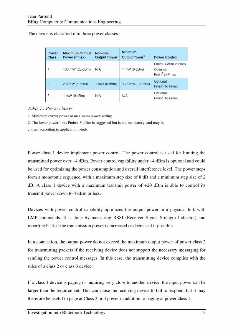
The device is classified into three power classes :
Table 1 : Power classes
1. Minimum output power at maximum power setting.
2. The lower power limit Pmin<-30dBm is suggested but is not mandatory, and may be
chosen according to application needs.
Power class 1 device implement power control. The power control is used for limiting the
transmitted power over +4 dBm. Power control capability under +4 dBm is optional and could
be used for optimizing the power consumption and overall interference level. The power steps
form a monotonic sequence, with a maximum step size of 8 dB and a minimum step size of 2
dB. A class 1 device with a maximum transmit power of +20 dBm is able to control its
transmit power down to 4 dBm or less.
Devices with power control capability optimizes the output power in a physical link with
LMP commands. It is done by measuring RSSI (Receiver Signal Strength Indicator) and
reporting back if the transmission power is increased or decreased if possible.
In a connection, the output power do not exceed the maximum output power of power class 2
for transmitting packets if the receiving device does not support the necessary messaging for
sending the power control messages. In this case, the transmitting device complies with the
rules of a class 2 or class 3 device.
If a class 1 device is paging or inquiring very close to another device, the input power can be
larger than the requirement. This can cause the receiving device to fail to respond, but it may
therefore be useful to page at Class 2 or 3 power in addition to paging at power class 1.

Jean Parrend BEng Computer & Communications Engineering
Investigation into Blutetooth Technology 16
3.1.2.1. Modulation characteristics
The Modulation is GFSK (Gaussian Frequency Shift Keying) with a bandwidthbit period
product BT=0.5. The Modulation index is between 0.28 and 0.35. A binary one is represented
by a positive frequency deviation, and a binary zero is represented by a negative frequency
deviation.
Figure 2 : GFSK parameters definition.
For each transmission, the minimum frequency deviation, Fmin = min{|Fmin+|, Fmin-},
which corresponds to 1010 sequence is no smaller than ±80% of the frequency deviation (fd)
with respect to the transmit frequency Ft, which corresponds to a 00001111 sequence.
In addition, the minimum frequency deviation is never smaller than 115 kHz. The data
transmitted has a symbol rate of 1 Ms/s.
The zero crossing error is the time difference between the ideal symbol period and the
measured crossing time. This is less than ± 1/8 of a symbol period.
3.1.3. Receiver characteristics
The reference sensitivity level referred to in this chapter is -70 dBm.

Jean Parrend BEng Computer & Communications Engineering
Investigation into Blutetooth Technology 17
3.1.3.1. Actual sensitivity level
The actual sensitivity level is defined as the input level for which a raw bit error rate (BER) of
0.1% is met. The receiver sensitivity is below or equal to – 70 dBm with any Bluetooth
transmitter.
3.1.3.2. Interference performance
The interference performance on Co-channel and adjacent 1 MHz and 2 MHz is measured
with the wanted signal 10 dB over the reference sensitivity level. For interference
performance on all other RF channels the wanted signal is 3 dB over the reference sensitivity
level. If the frequency of an interfering signal is outside of the band 2400-2483,5 MHz, the
out-of-band blocking specification apply.
The BER must be �0.1% for all the signal-to-interference ratios listed in this table :
Table 2 : Interference performance
1. In-band image frequency
2. If the image frequency � n*1 MHz, then the image reference frequency is defined as the closest n*1 MHz
frequency.
3.1.3.3. Out-of-band blocking
The out-of-band suppression (or rejection) is measured with the wanted signal 3 dB over the
reference sensitivity level.

Jean Parrend BEng Computer & Communications Engineering
Investigation into Blutetooth Technology 18
The BER must be � 0.1%. The out-of-band blocking fulfil the following requirements:
Table 3 : Out-of-band suppression (or rejection) requirements.
3.1.3.4. Maximum usable level
The maximum usable input level that the receiver operates at is greater than -20 dBm. The
BER must be less than or equal to 0.1% at –20 dBm input power.
3.1.3.5. Receiver signal strength indicator
If a device supports Receive Signal Strength Indicator (RSSI) the accuracy is +/-6 dBm.
3.2. Baseband
The Baseband and Link Control layer enables the physical RF link between Bluetooth
forming a piconet. As the Bluetooth RF system is a Frequency-Hopping-Spread-Spectrum
system in simpler terms packets are transmitted in defined time slots on defined frequencies,
this synchronizes the transmission hopping frequency and clock of different Bluetooth devices.
It provides two different kind of physical links with their corresponding baseband packets,
Synchronous Connection-Oriented and Asynchronous Connection-oriented which can be
transmitted in a multiplexing manner on the same RF link.
3.2.1. General description
The Bluetooth system provides a point-to-point connection or a point-to-multipoint
connection, see (a) and (b) in the figure below. In a point-to-point connection the physical
channel is shared between two Bluetooth devices. In a point-to-multipoint connection, the

Jean Parrend BEng Computer & Communications Engineering
Investigation into Blutetooth Technology 19
physical channel is shared among several Bluetooth devices. Two or more devices sharing the
same physical channel form a piconet. One Bluetooth device acts as the master of the piconet,
whereas the other device(s) act as slave(s). Up to seven slaves can be active in the piconet.
Additionally, many more slaves can remain connected in a parked state. These parked slaves
are not active on the channel, but remain synchronized to the master and can become active
without using the connection establishment procedure. Both for active and parked slaves, the
channel access is controlled by the master. Piconets that have common devices are called a
scatternet, see (c) in the figure below. Each piconet only has a single master, however, slaves
can participate in different piconets on a time-division multiplex basis. In addition, a master in
one piconet can be a slave in other piconets. Piconets are not be frequency synchronized and
each piconet has its own hopping sequence.
Figure 3 : Piconets with a single slave operation (a), a multi-slave operation (b) and a
scatternet operation (c).
Data is transmitted over the air in packets. The general packet format is shown in the figure
below. Each packet consists of 3 entities: the access code, the header, and the payload.
Figure 4 : Standard packet format.

Jean Parrend BEng Computer & Communications Engineering
Investigation into Blutetooth Technology 20
3.2.2. Clock
Every Bluetooth device has a native clock that is derived from a free running system clock.
For synchronization with other devices, offsets are used that, when added to the native clock,
provide temporary Bluetooth clocks that are mutually synchronized. It should be noted that
the Bluetooth clock has no relation to the time of day; it may therefore be initialized to any
value. The clock has a cycle of about a day. The clock is implemented with a 28-bit counter
that wrap around at 228-1. The least significant bit (LSB) ticks in units of 312.5 µs (i.e. half a
time slot), giving a clock rate of 3.2 kHz.
The clock determines critical periods and triggers the events in the device. Four periods are
important in the Bluetooth system: 312.5 µs, 625 µs, 1.25 ms, and 1.28 s; these periods
correspond to the timer bits CLK0, CLK1, CLK2, and CLK12, respectively, see figure below.
Figure 5 : Clock implemented with a 28-bit counter
In the different modes and states a device can reside in, the clock has different appearances:
• CLKN native clock
• CLK master clock
• CLKE estimated clock
CLKN
CLKN is the native clock and is the reference to all other clock appearances. In STANDBY
and in Park, Hold and Sniff mode the native clock may be driven by a low power oscillator
(LPO) with worst case accuracy (+/-250ppm). Otherwise, the native clock is driven by the
reference crystal oscillator with worst case accuracy of +/-20ppm.

Jean Parrend BEng Computer & Communications Engineering
Investigation into Blutetooth Technology 21
CLK
CLK is the master clock of the piconet. It is used for all timing and scheduling activities in the
piconet. All devices use the CLK to schedule their transmission and reception. The CLK is
derived from the native clock CLKN by adding an offset, see figure below. The offset is zero
for the master since CLK is identical to its own native clock CLKN. Each slave add an
appropriate offset to its CLKN such that the CLK corresponds to the CLKN of the master.
Although all CLKNs in the devices run at the same nominal rate, mutual drift causes
inaccuracies in CLK. Therefore, the offsets in the slaves is regularly updated such that CLK is
approximately CLKN of the master.
Figure 6 : Derivation of CLK in master (a) and in slave (b).
CLKE
A paging device uses an estimate of the native clock of the page scanning device, CLKE; i.e.
an offset shall be added to the CLKN of the pager to approximate the CLKN of the recipient,
see figure below. CLKE is derived from the reference CLKN by adding an offset. By using
the CLKN of the recipient, the pager might be able to speed up the connection establishment.
Figure 7 : Derivation of CLKE.

Jean Parrend BEng Computer & Communications Engineering
Investigation into Blutetooth Technology 22
3.2.3. Device addressing
Each Bluetooth device is allocated a unique 48-bit Bluetooth device address (BD_ADDR).
This address is obtained by the manufacturer from the IEEE Registration Authority. The
address is divided into the following three fields:
• LAP field: lower address part consisting of 24 bits
• UAP field: upper address part consisting of 8 bits
• NAP field: non-significant address part consisting of 16 bits
The LAP and UAP form the significant part of the BD_ADDR. The bit pattern in the figure
below is an example BD_ADDR.
Figure 8 : Format of BD_ADDR.
The BD_ADDR may take any values except the 64 reserved LAP values for general and
dedicated inquiries.
3.2.4. Access codes
In the Bluetooth system all transmissions over the physical channel begin with an access
code. Three different access codes are defined:
• device access code (DAC)
• channel access code (CAC)
• inquiry access code (IAC)
All access codes are derived from the LAP of a device address or an inquiry address. The
device access code is used during page, page scan and page response substates and is
derived from the paged device’s BD_ADDR. The device access code is used in the
CONNECTION state and forms the beginning of all packets exchanged on the piconet
Jean Parrend BEng Computer & Communications Engineering
Investigation into Blutetooth Technology 23
physical channel. The channel access code is derived from the LAP of the master’s
BD_ADDR. Finally, the inquiry access code is used in the inquiry substate. There is one
general IAC (GIAC) for general inquiry operations and there are 63 dedicated IACs (DIACs)
for dedicated inquiry operations. The access code also indicates to the receiver the arrival of a
packet. It is used for timing synchronization and offset compensation. The receiver correlates
against the entire synchronization word in the access code, providing very robust signalling.
3.2.5. Physical channels
The lowest architectural layer in the Bluetooth system is the physical channel. A number of
types of physical channel are defined. All Bluetooth physical channels are characterized by
the combination of a pseudo-random frequency hopping sequence, the specific slot timing of
the transmissions, the access code and packet header encoding. These aspects, together with
the range of the transmitters, define the signature of the physical channel. For the basic and
adapted piconet physical channels frequency hopping is used to change frequency periodically
to reduce the effects of interference and to satisfy local regulatory requirements. Two devices
that wish to communicate use a shared physical channel for this communication. To achieve
this, their transceivers must be tuned to the same RF frequency at the same time, and they
must be within a nominal range of each other.
Given that the number of RF carriers is limited and that many Bluetooth devices may be
operating independently within the same spatial and temporal area there is a strong likelihood
of two independent Bluetooth devices having their transceivers tuned to the same RF carrier,
resulting in a physical channel collision. To mitigate the unwanted effects of this collision
each transmission on a physical channel starts with an access code that is used as a correlation
code by devices tuned to the physical channel. This channel access code is a property of the
physical channel. The access code is always present at the start of every transmitted packet.
Four Bluetooth physical channels are defined. Each is optimized and used for a different
purpose. Two of these physical channels (the basic piconet channel and adapted piconet
channel) are used for communication between connected devices and are associated with a
specific piconet. The remaining physical channels are used for discovering (the inquiry scan
channel) and connecting (the page scan channel) Bluetooth devices.
Jean Parrend BEng Computer & Communications Engineering
Investigation into Blutetooth Technology 24
A Bluetooth device can only use one of these physical channels at any given time. In order to
support multiple concurrent operations the device uses time-division multiplexing between
the channels. In this way a Bluetooth device can appear to operate simultaneously in several
piconets, as well as being discoverable and connectable. Whenever a Bluetooth device is
synchronized to the timing, frequency and access code of a physical channel it is said to be
'connected' to this channel (whether or not it is actively involved in communications over the
channel.) At a minimum, a device need only be capable of connection to one physical channel
at a time, however, advanced devices may be capable of connecting simultaneously to more
than one physical channel.
3.2.5.1. Physical channel definition
Physical channels are defined by a pseudo-random RF channel hopping sequence, the packet
(slot) timing and an access code. The hopping sequence is determined by the UAP (Upper
Address Part) and LAP (Lower address Part) of a Bluetooth device address and the selected
hopping sequence. The phase in the hopping sequence is determined by the Bluetooth clock.
All physical channels are subdivided into time slots whose length is different depending on
the physical channel. Within the physical channel, each reception or transmission event is
associated with a time slot or time slots. For each reception or transmission event an RF
channel is selected by the hop selection kernel. The maximum hop rate is 1600 hops/s in the
CONNECTION state and the maximum is 3200 hops/s in the inquiry and page substates.
The following physical channels are defined:
• basic piconet physical channel
• adapted piconet physical channel
• page scan physical channel
• inquiry scan physical channel
3.2.5.2. Hop selection
Bluetooth devices use the hopping kernel as defined in this section. In total, six types of
hopping sequence are defined −�five for the basic hop system and one for an adapted set of
hop locations used by adaptive frequency hopping (AFH).

Jean Parrend BEng Computer & Communications Engineering
Investigation into Blutetooth Technology 25
These sequences are:
• A page hopping sequence with 32 wake-up frequencies distributed equally over the 79
MHz.
• A page response hopping sequence covering 32 response frequencies that are in a one-to-
one correspondence to the current page hopping sequence. The master and slave use different
rules to obtain the same sequence.
• An inquiry hopping sequence with 32 wake-up frequencies distributed equally over the 79
MHz.
• An inquiry response hopping sequence covering 32 response frequencies that are in a one-
to-one correspondence to the current inquiry hopping sequence.
• A basic channel hopping sequence which has a very long period length, which does not
show repetitive patterns over a short time interval, and which distributes the hop frequencies
equally over the 79 MHz during a short time interval.
• An adapted channel hopping sequence derived from the basic channel hopping sequence
which uses the same channel mechanism and may use fewer than 79 frequencies. The adapted
channel hopping sequence is only used in place of the basic channel hopping sequence. All
other hopping sequences are not affected by hop sequence adaptation.
3.2.6. Physical links
A physical link represents a baseband connection between devices. A physical link is always
associated with exactly one physical channel. Physical links have common properties that
apply to all logical transports on the physical link. The common properties of physical links
are:
• Power control
• Link supervision
• Encryption
• Channel quality-driven data rate change
• Multi-slot packet control
A connection can break down due to various reasons such as a device moving out of range,
encountering severe interference or a power failure condition. Since this may happen without
any prior warning, the link is monitored on both the master and the slave side to avoid

Jean Parrend BEng Computer & Communications Engineering
Investigation into Blutetooth Technology 26
possible collisions when the logical transport address or parked member address is reassigned
to another slave. To be able to detect link loss, both the master and the slave use a link
supervision timer, Tsupervision. Upon reception of a valid packet header with one of the slave's
addresses on the physical link, the timer shall be reset. If at any time in CONNECTION
state, the timer reaches the supervisionTO value, the connection shall be considered
disconnected. the same link supervision timer is used for SCO, eSCO, and ACL logical
transports.
The timeout period, supervisionTO, is negotiated by the Link Manager. Its value is chosen so
that the supervision timeout will be longer than hold and sniff periods. Link supervision of a
parked slave shall be done by unparking and re-parking the slave.
3.2.7. Logical transports
Between master and slave(s), different types of logical transports may be established. Five
logical transports have been defined:
• Synchronous Connection-Oriented (SCO) logical transport
• Extended Synchronous Connection-Oriented (eSCO) logical transport
• Asynchronous Connection-Oriented (ACL) logical transport
• Active Slave Broadcast (ASB) logical transport
• Parked Slave Broadcast (PSB) logical transport
The synchronous logical transports are point-to-point logical transports between a master and
a single slave in the piconet. The synchronous logical transports typically support time-
bounded information like voice or general synchronous data. The master maintains the
synchronous logical transports by using reserved slots at regular intervals.
In addition to the reserved slots the eSCO logical transport may have a retransmission
window after the reserved slots.
The ACL logical transport is also a point-to-point logical transport between the master and a
slave. In the slots not reserved for synchronous logical transport(s), the master can establish
an ACL logical transport on a per-slot basis to any slave, including the slave(s) already
engaged in a synchronous logical transport.

Jean Parrend BEng Computer & Communications Engineering
Investigation into Blutetooth Technology 27
The ASB logical transport is used by a master to communicate with active slaves.
The PSB logical transport is used by a master to communicate with parked slaves.
3.2.7.1. Synchronous logical transport
The first type of synchronous logical transport, the SCO logical transport is a symmetric,
point-to-point link between the master and a specific slave. The SCO logical transport
reserves slots and can therefore be considered as a circuit-switched connection between the
master and the slave. The master may support up to three SCO links to the same slave or to
different slaves. A slave may support up to three SCO links from the same master, or two
SCO links if the links originate from different masters. SCO packets are never retransmitted.
The second type of synchronous logical transport, the eSCO logical transport, is a point-to-
point logical transport between the master and a specific slave. eSCO logical transports may
be symmetric or asymmetric. Similar to SCO, eSCO reserves slots and can therefore be
considered a circuit-switched connection between the master and the slave. In addition to the
reserved slots, eSCO supports a retransmission window immediately following the reserved
slots. Together, the reserved slots and the retransmission window form the complete eSCO
window.
3.2.7.2. Asynchronous logical transport
In the slots not reserved for synchronous logical transports, the master may exchange packets
with any slave on a per-slot basis. The ACL logical transport provides a packet-switched
connection between the master and all active slaves participating in the piconet. Both
asynchronous and isochronous services are supported. Between a master and a slave only a
single ACL logical transport shall exist. For most ACL packets, packet retransmission is
applied to assure data integrity.
ACL packets not addressed to a specific slave are considered as broadcast packets and should
be read by every slave. If there is no data to be sent on the ACL logical transport and no
polling is required, no transmission is required.

Jean Parrend BEng Computer & Communications Engineering
Investigation into Blutetooth Technology 28
3.2.7.3. Active slave broadcast transport
The active slave broadcast logical transport (ASB) is used to transport L2CAP user traffic to
all devices in the piconet that are currently connected to the piconet physical channel that is
used by the ASB. There is no acknowledgement protocol and the traffic is uni-directional
from the piconet master to the slaves. The ASB logical transport may only be used for L2CAP
group traffic.
The ASB logical transport is unreliable. To improve reliability somewhat each packet is
transmitted a number of times. An identical sequence number is used to assist with filtering
retransmissions at the slave device.
The ASB logical transport is identified by the reserved, all-zero, LT_ADDR. Packets on the
ASB logical transport may be sent by the master at any time.
3.2.7.4. Parked slave broadcast transport
The parked slave broadcast logical transport is used for communication from the master to the
slaves that are parked. The PSB logical transport is more complex than the other logical
transports as it consists of a number of phases, each having a different purpose. These phases
are the control information phase (used to carry the LMP logical link), the user information
phase (used to carry the L2CAP logical link), and the access phase (carrying baseband
signalling).
3.2.8. Logical links
Five logical links are defined:
• Link Control (LC)
• ACL Control (ACL-C)
• User Asynchronous/Isochronous (ACL-U)
• User Synchronous (SCO-S)
• User Extended Synchronous (eSCO-S)
The control logical links LC and ACL-C are used at the link control level and link manager
level, respectively. The ACL-U logical link is used to carry either asynchronous or

Jean Parrend BEng Computer & Communications Engineering
Investigation into Blutetooth Technology 29
isochronous user information. The SCO-S, and eSCO-S logical links are used to carry
synchronous user information. The LC logical link is carried in the packet header, all other
logical links are carried in the packet payload. The ACL-C and ACL-U logical links are
indicated in the logical link ID, LLID, field in the payload header. The SCO-S and eSCO-S
logical links are carried by the synchronous logical transports only; the ACL-U link is
normally carried by the ACL logical transport; however, they may also be carried by the data
in the DV packet on the SCO logical transport. The ACL-C link may be carried either by the
SCO or the ACL logical transport.
3.2.8.1. Link Control logical link (LC)
The LC control logical link is mapped onto the packet header. This logical link carries low
level link control information like ARQ, flow control, and payload characterization. The LC
logical link is carried in every packet except in the ID packet which does not have packet
header.
3.2.8.2. ACL-Control logical link (ACL-C)
The ACL-C logical link carries control information exchanged between the link managers of
the master and the slave(s). The ACL-C logical link uses DM1 packets. The ACL-C logical
link is indicated by the LLID code 11 in the payload header.
3.2.8.3. User asynchronous/isochronous logical link (ACL-U)
The ACL-U logical link carries L2CAP asynchronous and isochronous user data. These
messages may be transmitted in one or more baseband packets. For fragmented messages, the
start packet uses an LLID code of 10 in the payload header. Remaining continuation packets
use LLID code 01. If there is no fragmentation, all packets use the LLID start code 10.
3.2.8.4. User synchronous data logical link (SCO-S)
The SCO-S logical link carries transparent synchronous user data. This logical link is carried
over the synchronous logical transport SCO.

Jean Parrend BEng Computer & Communications Engineering
Investigation into Blutetooth Technology 30
3.2.8.5. User extended synchronous data logical link (eSCO-S)
The eSCO-S logical link also carries transparent synchronous user data. This logical link is
carried over the extended synchronous logical transport eSCO.
3.2.8.6. Logical link properties
The ACL-C logical link has a higher priority than the ACL-U logical link when scheduling
traffic on the shared ACL logical transport, except in the case when retransmissions of
unacknowledged ACL packets is given priority over traffic on the ACL-C logical link. The
ACL-C logical link also has priority over traffic on the SCO-S and eSCO-S logical links but
opportunities for interleaving the logical links are taken.
3.2.9. Packets
Bluetooth devices uses the packets as defined in the following sections.
3.2.9.1. General formats
The general packet format is shown in the figure below. Each packet consists of 3 entities: the
access code, the header, and the payload. In the figure, the number of bits per entity is
indicated.
Figure 9 : General packet format.
The access code is 72 or 68 bits and the header is 54 bits. The payload ranges from zero to a
maximum of 2745 bits. Different packet types have been defined. Packet may consist of:
• the shortened access code only
• the access code and the packet header
• the access code, the packet header and the payload.
Jean Parrend BEng Computer & Communications Engineering
Investigation into Blutetooth Technology 31
3.2.9.2. Bit ordering
The bit ordering when defining packets and messages in the Baseband Specification, follows
the Little Endian format.
The following rules apply:
• The least significant bit (LSB) corresponds to b0;
• The LSB is the first bit sent over the air;
• In illustrations, the LSB is shown on the left side;
Furthermore, data fields generated internally at baseband level, such as the packet header
fields and payload header length, is transmitted with the LSB first. For instance, a 3-bit
parameter X=3 is sent as:
B0 b1 b1 = 110
over the air where 1 is sent first and 0 is sent last.
3.2.9.3. Access code
Every packet starts with an access code. If a packet header follows, the access code is 72 bits
long, otherwise the access code is 68 bits long and is known as a shortened access code. The
shortened access code does not contain a trailer. This access code is used for synchronization,
DC offset compensation and identification. The access code identifies all packets exchanged
on a physical channel: all packets sent in the same physical channel are preceded by the same
access code. In the receiver of the device, a sliding correlator correlates against the access
code and triggers when a threshold is exceeded. This trigger signal is used to determine the
receive timing. The shortened access code is used in paging, inquiry, and park. In this case,
the access code itself is used as a signalling message and neither a header nor a payload is
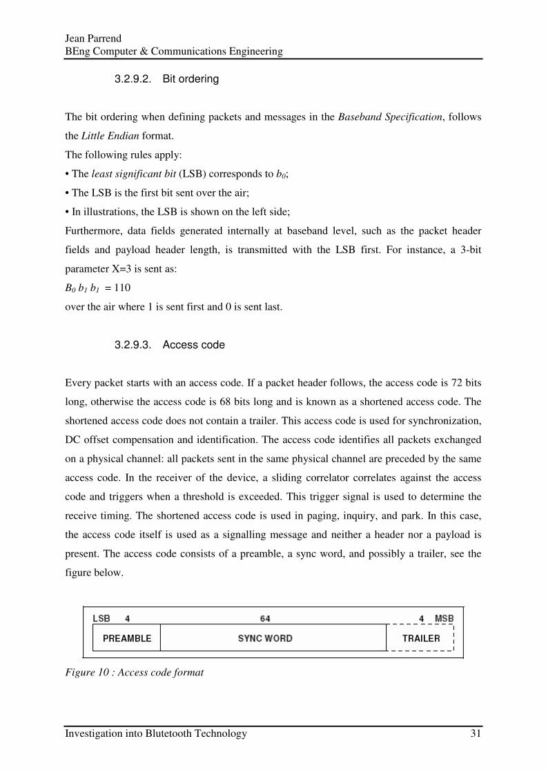
present. The access code consists of a preamble, a sync word, and possibly a trailer, see the
figure below.
Figure 10 : Access code format

Jean Parrend BEng Computer & Communications Engineering
Investigation into Blutetooth Technology 32
3.2.9.4. Packet header
The header contains link control (LC) information and consists of 6 fields:
• LT_ADDR: 3- bit logical transport address
• TYPE: 4-bit type code
• FLOW: 1-bit flow control
• ARQN: 1-bit acknowledge indication
• SEQN: 1-bit sequence number
• HEC: 8-bit header error check
The total header, including the HEC, consists of 18 bits, see the figure below, and is encoded
with a rate 1/3 FEC (not shown) resulting in a 54-bit header. The LT_ADDR and TYPE fields
are sent LSB first.
Figure 11 : Header format.
3.2.9.4.1. Packet types
The packets used on the piconet are related to the logical transports they are used in. Three
logical transports with distinct packet types are defined : the SCO logical transport, the eSCO
logical transport, and the ACL logical transport. For each of these logical transports, 15
different packet types can be defined.
To indicate the different packets on a logical transport, the 4-bit TYPE code is used. The
packet types are divided into four segments. The first segment is reserved for control packets.
All control packets occupy a single time slot. The second segment is reserved for packets
occupying a single time slot. The third segment is reserved for packets occupying three time
slots. The fourth segment is reserved for packets occupying five time slots. The slot
occupancy is reflected in the segmentation and can directly be derived from the type code.
The following table summarizes the packets defined for the SCO, eSCO, and ACL logical
transport types.

Jean Parrend BEng Computer & Communications Engineering
Investigation into Blutetooth Technology 33
Table 4 : Packets defined for synchronous and asynchronous logical transport types.
3.2.9.5. Payload format
In the payload, two fields are distinguished: the synchronous data field and the asynchronous
data field. The ACL packets only have the asynchronous data field and the SCO and eSCO
packets only have the synchronous data field − with the exception of the DV packets which
have both.
3.2.9.6. Packet summary
A summary of the packets and their characteristics is shown in the three following tables. The
payload represents the packet payload excluding FEC, CRC, and payload header.

Jean Parrend BEng Computer & Communications Engineering
Investigation into Blutetooth Technology 34
Table 5 : Link control packets
Table 6 : ACL packets
Table 7 : Synchronous packets
1. Items followed by ‘D’ relate to data field only.

Jean Parrend BEng Computer & Communications Engineering
Investigation into Blutetooth Technology 35
3.2.10. Bitstream processing
Before the payload is sent over the air interface, several bit manipulations are performed in
the transmitter to increase reliability and security. An HEC is added to the packet header, the
header bits are scrambled with a whitening word, and FEC coding is applied. In the receiver,
the inverse processes are carried out. The figure below shows the processes carried out for the
packet header both at the transmit and the receive side. All header bit processes are
mandatory.
Figure 12 : Header bit processes.
3.2.11. States/modes
This section describes the several states of operation of the devices are defined to establish a
piconet and add a device to or release a device from a piconet.
3.2.11.1. Overview of states
The next figure shows a state diagram illustrating the different states used in the link
controller. There are three major states: STANDBY, CONNECTION, and PARK; in
addition, there are seven substates, page, page scan, inquiry, inquiry scan, master
response, slave response, and inquiry response. The substates are interim states that are
used to establish connections and enable device discovery. To move from one state or substate
to another, either commands from the link manager are used, or internal signals in the link
controller are used (such as the trigger signal from the correlator and the timeout signals).

Jean Parrend BEng Computer & Communications Engineering
Investigation into Blutetooth Technology 36
Figure 13 : State diagram of link controller.
3.2.11.2. Standby state
The STANDBY state is the default state in the device. In this state, the device may be in a
low-power mode. Only the native clock is running at the accuracy of the LPO (or better).
The controller may leave the STANDBY state to scan for page or inquiry messages, or to
page or inquiry itself.
3.2.11.3. Connection state
In the CONNECTION state, the connection has been established and packets can be sent
back and forth. In both devices, the channel (master) access code, the master's Bluetooth
clock, and the AFH_channel_map are used. CONNECTION state uses the basic or adapted
channel hopping sequence.
The CONNECTION state starts with a POLL packet sent by the master to verify the switch
to the master’s timing and channel frequency hopping. The slave may respond with any type
of packet. If the slave does not receive the POLL packet or the master does not receive the

Jean Parrend BEng Computer & Communications Engineering
Investigation into Blutetooth Technology 37
response packet for newconnectionTO number of slots, both devices shall return to page/page
scan substates.
The first information packets in the CONNECTION state contain control messages that
characterize the link and give more details regarding the devices. These messages are
exchanged between the link managers of the devices. For example, they may define the SCO
logical transport and the sniff parameters. Then the transfer of user information can start by
alternately transmitting and receiving packets.
The CONNECTION state is left through a detach or reset command. The detach command
is used if the link has been disconnected in the normal way; all configuration data in the link
controller remain valid. The reset command is a soft reset of the link controller.
In the CONNECTION state, if a device is not going to be nominally present on the channel
at all times it may describe its unavailability by using sniff mode or hold mode (see figure
below).
Figure 14 : Connection state.
3.2.11.3.1. Active mode
In the active mode, both master and slave actively participate on the channel. Up to seven
slaves may be in the active mode at any given time. The master schedules the transmission
based on traffic demands to and from the different slaves. In addition, it supports regular
transmissions to keep slaves synchronized to the channel. Slaves in the active mode listen in
the master-to-slave slots for packets. These devices are known as active slaves. If an active
slave is not addressed, it may sleep until the next new master transmission. Slaves can derive

Jean Parrend BEng Computer & Communications Engineering
Investigation into Blutetooth Technology 38
the number of slots the master has reserved for transmission from TYPE field in the packet
header; during this time, the non-addressed slaves do not have to listen on the master-to-slave
slots. When a device is participating in multiple piconets it should listen in the master-to-slave
slot for the current piconet.
It is recommended that a device not be away from each piconet in which it is participating for
more than Tpoll slots. A periodic master transmission is required to keep the slaves
synchronized to the channel. Since the slaves only need the channel access code to
synchronize, any packet type can be used for this purpose. Only the slave that is addressed by
one of its LT_ADDRs (primary or secondary) may return a packet in the next slave-to-master
slot. If no valid packet header is received, the slave may only respond in its reserved SCO or
eSCO slave-to-master slot. In the case of a broadcast message, no slave return a packet.
3.2.11.3.2. Sniff mode
In sniff mode, the duty cycle of the slave’s activity in the piconet may be reduced. If a slave is
in active mode on an ACL logical transport, it listens in every ACL slot to the master traffic,
unless that link is being treated as a scatternet link or is absent due to hold mode. With sniff
mode, the time slots when a slave is listening are reduced, so the master only transmits to a
slave in specified time slots. The sniff anchor points are spaced regularly with an interval of
Tsniff.
Figure 15 : Sniff anchor points
3.2.11.3.3. Hold mode
During the CONNECTION state, the ACL logical transport to a slave can be put in a hold
mode. In hold mode the slave temporarily does not support ACL packets on the channel. Any

Jean Parrend BEng Computer & Communications Engineering
Investigation into Blutetooth Technology 39
synchronous packet during reserved synchronous slots (from SCO and eSCO links) is
supported. With the hold mode, capacity can be made free to do other things like scanning,
paging, inquiring, or attending another piconet. The device in hold mode can also enter a
lowpower sleep mode. During hold mode, the slave device keeps its logical transport
address(es) (LT_ADDR).
Prior to entering hold mode, master and slave agree on the time duration the slave remains in
hold mode. A timer is initialized with the holdTO value. When the timer is expired, the slave
wakes up, synchronize to the traffic on the channel and will wait for further master
transmissions.
3.2.11.4. Park state
When a slave does not need to participate on the piconet channel, but still needs to remain
synchronized to the channel, it can enter PARK state. PARK state is a state with very little
activity in the slave. In the PARK state, the slave gives up its logical transport address
LT_ADDR. Instead, it receives two new addresses to be used in the PARK state :
• PM_ADDR: 8-bit Parked Member Address
• AR_ADDR: 8-bit Access Request Address
The PM_ADDR distinguishes a parked slave from the other parked slaves. This address may
be used in the master-initiated unpark procedure. In addition to the PM_ADDR, a parked
slave may also be unparked by its 48-bitBD_ADDR. The all-zero PM_ADDR is a reserved
address: if a parked device has the all-zero PM_ADDR it can only be unparked by the
BD_ADDR. In that case, the PM_ADDR has no meaning. The AR_ADDR is used by the
slave in the slave-initiated unpark procedure. All messages sent to the parked slaves are
carried by broadcast packets. The parked slave wakes up at regular intervals to listen to the
channel in order to re-synchronize and to check for broadcast messages. To support the
synchronization and channel access of the parked slaves, the master supports a beacon train.
The beacon structure is communicated to the slave when it is parked. When the beacon
structure changes, the parked slaves are updated through broadcast messages.

Jean Parrend BEng Computer & Communications Engineering
Investigation into Blutetooth Technology 40
The master maintains separate non-overlapping park beacon structures for each hop sequence.
The beacon structures does not overlap either their beacon slots or access windows. In
addition for using it for low power consumption, park is used to connect more than seven
slaves to a single master. At any one time, only seven slaves can be in the CONNECTION
state. However, by swapping active and parked slaves out respectively in the piconet, the
number of slaves can be much larger (255 if the PM_ADDR is used, and an arbitrarily large
number if the BD_ADDR is used).
3.3. LMP : Link Manager Protocol
The link manager protocol is responsible for link set-up between Bluetooth devices. This
includes setting up of security functions like authentication and encryption by generating,
exchanging and checking of link and encryption keys and the control and negotiation of
baseband packet sizes. Furthermore it controls the power modes and duty cycles of the
Bluetooth radio device, and the connection states of a Bluetooth unit in a piconet.
3.3.1. General aspects
The Link Manager Protocol (LMP) is used to control and negotiate all aspects of the operation
of the Bluetooth connection between two devices. This includes the set-up and control of
logical transports and logical links, and for control of physical links. The Link Manager
Protocol is used to communicate between the Link Managers (LM) on the two devices which
are connected by the ACL logical transport. All LMP messages apply solely to the physical
link and associated logical links and logical transports between the sending and receiving
devices. The protocol is made up of a series of messages which is transferred over the ACL-C
logical link on the default ACL logical transport between two devices. LMP messages are
interpreted and acted-upon by the LM and are not be directly propagated to higher protocol
layers.

Jean Parrend BEng Computer & Communications Engineering
Investigation into Blutetooth Technology 41
Figure 16 : Link Manager Protocol signalling layer.
3.3.2. Message transport
LMP messages are exchanged over the ACL-C logical link that is carried on the default ACL
logical transport. The ACL-C logical link is distinguished from the ACL-U (which carries
L2CAP and user data) by the Logical Link Identifier (LLID) field carried in the payload
header of variable-length packets.
The ACL-C has a higher priority than other traffic. The error detection and correction
capabilities of the baseband ACL logical transport are generally sufficient for the
requirements of the LMP. Therefore LMP messages do not contain any additional error
detection information beyond what can be realized by means of sanity checks performed on
the contents of LMP messages. Any such checks and protections to overcome undetected
errors in LMP messages is an implementation matter.
3.3.3. Synchronization
LMP messages are carried on the ACL-C logical link, which does not guarantee a time to
deliver or acknowledge packets. LMP procedures take account of this when synchronizing
state changes in the two devices. For example, criteria are defined that specify when a logical
transport address (LT_ADDR) may be re-used after it becomes available due to a device
leaving the piconet or entering the park state. Other LMP procedures, such as hold or role
switch include the Bluetooth clock as a parameter in order to define a fixed synchronization
point. The transitions into and out of sniff mode are protected with a transition mode.

Jean Parrend BEng Computer & Communications Engineering
Investigation into Blutetooth Technology 42
The LC (Link Controller) normally attempts to communicate with each slave no less often
than every Tpoll slots based on the Tpoll for that slave.
Figure 17 : Transmission of a message from master to slave1.
1. Note the diagram shows the limiting case where the master transmits the message at intervals of Tpoll. In the
case of heavy interference improved performance is gained by transmitting more often.
This figure illustrates the fundamental problem. It shows the transmission of a packet from
the master to the slave in conditions of heavy interference for illustrative purposes. It is
obvious that neither side can determine the value of either Tdeliver or Tack. It is therefore not
possible to use simple messages to identify uniquely the instant at which a state change occurs
in the other device.
3.3.4. Packet format
Each PDU (Protocol Data Unit) is assigned either a 7 or a 15 bit opcode used to uniquely
identify different types of PDUs. The first 7 bits of the opcode and a transaction ID are
located in the first byte of the payload body. If the initial 7 bits of the opcode have one of the
special escape values 124-127 then an additional byte of opcode is located in the second byte

Jean Parrend BEng Computer & Communications Engineering
Investigation into Blutetooth Technology 43
of the payload and the combination uniquely identifies the PDU. The FLOW bit in the packet
header is always 1 and is ignored on reception. If the PDU contains one or more parameters
these are placed in the payload starting immediately after the opcode, i.e. at byte 2 if the PDU
has a 7 bit opcode or byte 3 if the PDU has a 15 bit opcode. The number of bytes used
depends on the length of the parameters. All parameters have a little-endian format, i.e. the
least significant byte is transferred first. LMP messages are transmitted using DM1 packets,
however if an HV1 SCO link is in use and the length of the payload is less than 9 bytes then
DV packets may be used.
Figure 18 : Payload body when LMP PDUs are sent.
3.3.5. Transactions
The LMP operates in terms of transactions. A transaction is a connected set of message
exchanges which achieve a particular purpose. All PDUs which form part of the same
transaction have the same value for the transaction ID which is stored as part of the first byte
of the opCode.
The transaction ID is in the least significant bit. It is 0 if the PDU forms part of a transaction
that was initiated by the master and 1 if the transaction was initiated by the slave. Each
sequence is defined as a transaction. For pairing and encryption, all sequences belonging to
each section are counted as one transaction and use the same transaction ID. For connection
establishment, LMP_host_connection_req and the response with LMP_accepted or

Jean Parrend BEng Computer & Communications Engineering
Investigation into Blutetooth Technology 44
LMP_not_accepted form one transaction and have the transaction ID of 0.
LMP_setup_complete is a stand-alone PDU, which forms a transaction by itself.
For error handling, the PDU to be rejected and LMP_not_accepted or LMP_not_accepted_ext
form a single transaction.
3.3.6. Error handling
If the Link Manager (LM) receives a PDU with unrecognized opcode, it responds with the
error code unknown LMP PDU. The opcode parameter that is echoed back is the
unrecognized opcode.
If the LM receives a PDU with invalid parameters, it responds with the error code invalid
LMP parameters.
If the LM receives a PDU that is not allowed, and the PDU normally expects a PDU reply, the
LM returns the error code PDU not allowed.
If the PDU normally doesn’t expect a reply, the PDU will be ignored.
The reception of an optional PDU which is not supported is handled in one of two ways:
- If the LM simply does not know the opcode (e.g. it was added at a later version of the
specification) it responds with the error code unknown LMP PDU.
- If the LM recognises the PDU as optional but unsupported then it replies with the error code
unsupported LMP feature.
3.4. HCI : Host Controller Interface
This part of my report describes the functional specifications for the Host Controller Interface
(HCI). The HCI specification defines a standard interface-independent method of
communicating with the Bluetooth chip. The software stack on the host processor
communicates with the Bluetooth hardware using HCI commands. Since no hardware-
specific knowledge is needed the Bluetooth stack software can easily be ported from one
Bluetooth chip to another. The HCI layer is part of the Bluetooth stack, but it does not

Jean Parrend BEng Computer & Communications Engineering
Investigation into Blutetooth Technology 45
constitute a peer-to-peer communication layer, since the HCI command and response
messages do not flow over the air link. The HCI provides a uniform interface method of
accessing the Bluetooth controller capabilities.
3.4.1. Overview of host controller transport layer
The host driver stack has a transport layer between the Host Controller driver and the Host.
The main goal of this transport layer is transparency. The Host Controller driver (which
interaces to the Controller) should be independent of the underlying transport technology. Nor
should the transport require any visibility into the data that the Host Controller driver passes
to the Controller. This allows the interface (HCI) or the Controller to be upgraded without
affecting the transport layer.
3.4.2. Overview of commands and events
The commands and events are sent between the Host and the Controller. These are grouped
into logical groups by function.
Table 8 : Overview of commands and events
Jean Parrend BEng Computer & Communications Engineering
Investigation into Blutetooth Technology 46
3.4.3. HCI flow control
Flow control is used in the direction from the Host to the Controller to avoid overflowing the
Controller data buffers with ACL data destined for a remote device (using a connection
handle) that is not responding. The Host manages the data buffers of the Controller.
3.4.4. HCI formats
The HCI provides a uniform command method of accessing the Bluetooth controller
capabilities. The HCI Link commands provide the Host with the ability to control the link
layer connections to other Bluetooth devices. These commands typically involve the Link
Manager (LM) to exchange LMP commands with remote Bluetooth devices. The HCI Policy
commands are used to affect the behavior of the local and remote LM. These Policy
commands provide the Host with methods of influencing how the LM manages the piconet.
HCI commands may take different amounts of time to be completed. Therefore, the results of
commands will be reported back to the Host in the form of an event. For example, for most
HCI commands the Controller will generate the Command Complete event when a command
is completed. This event contains the return parameters for the completed HCI command. For
enabling the Host to detect errors on the HCI-Transport Layer, there needs to be a timeout
between the transmission of the Host’s command and the reception of the Controller’s
response.
3.5. L2CAP : Logical Link Control and Adaptation Protocol
The Bluetooth logical link control and adaptation protocol (L2CAP) adapts upper layer
protocols over the baseband. It can be thought to work in parallel with LMP in difference that
L2CAP provides services to the upper layer when the payload data is never sent at LMP
messages.

Jean Parrend BEng Computer & Communications Engineering
Investigation into Blutetooth Technology 47
3.5.1. General aspects
L2CAP is layered over the Link Controller Protocol and resides in the data link layer as
shown in the figure below. L2CAP provides connection-oriented and connectionless data
services to upper layer protocols with protocol multiplexing capability, segmentation and
reassembly operation, and group abstractions. L2CAP permits higher level protocols and
applications to transmit and receive upper layer data packets (L2CAP Service Data Units,
SDU) up to 64 kilobytes in length. L2CAP also permits per-channel flow control and
retransmission via the Flow Control and Retransmission Modes.
Figure 19 : L2CAP within protocol layers
The L2CAP layer provides logical channels, named L2CAP channels, which are mapped to
L2CAP logical links supported by an ACL logical transport.
3.5.2. L2CAP features
The functional requirements for L2CAP include protocol/channel multiplexing, segmentation
and reassembly (SAR), per-channel flow control, error control and group management. The
following figure illustrates how L2CAP data flows fit into the Bluetooth Protocol Stack.
L2CAP lies above the Link Controller Protocol and interfaces with other communication
protocols such as the Bluetooth Service Discovery Protocol (SDP), RFCOMM, Telephony
Control (TCS) and Bluetooth Network Encapsulation Protocol (BNEP). Voice-quality
channels for audio and telephony applications and synchronous transparent connections are

Jean Parrend BEng Computer & Communications Engineering
Investigation into Blutetooth Technology 48
usually run over synchronous logical transports, but packetized audio data, such as IP
Telephony, may be sent using communication protocols running over L2CAP.
Figure 20 : L2CAP data flows in Bluetooth Protocol Architecture
The figure below breaks down L2CAP into its architectural components. The Channel
Manager provides the control plane functionality and is responsible for all internal signalling,
L2CAP peer-to-peer signalling and signalling with higher and lower layers. The
Retransmission and Flow Control block provides per-channel flow control and optional
retransmission for applications that require it. The Resource Manager is responsible for
providing a frame relay service to the Channel Manager, the Retransmission and Flow
Control block and those application data streams that do not require Retransmission and Flow
Control services. It is responsible for coordinating the transmission and reception of packets
related to multiple L2CAP channels over the facilities offered at the lower layer interface.
Figure 21 : L2CAP architectural blocks

Jean Parrend BEng Computer & Communications Engineering
Investigation into Blutetooth Technology 49
• Protocol/channel multiplexing
L2CAP supports multiplexing because the Baseband Protocol does not support any ’type’
field identifying the higher layer protocol being multiplexed above it. During channel setup,
protocol multiplexing capability is use to route the connection request to the correct upper
layer protocol. For data transfer, logical channel multiplexing is needed to distinguish
between multiple upper layer entities. There may be more than one upper layer entity using
the same protocol.
• Segmentation and reassembly
With the frame relay service offered by the Resource Manager, the length of transport frames
is controlled by the individual applications running over L2CAP. Many multiplexed
applications are better served if L2CAP has control over the PDU length. This provides the
following benefits:
a) Segmentation will allow the interleaving of application data units in order to satisfy latency
requirements.
b) Memory and buffer management is easier when L2CAP controls the packet size.
c) Error correction by retransmission can be made more efficient.
d) The amount of data that is destroyed when an L2CAP PDU is corrupted or lost can be
made smaller than the application's data unit.
e) The application is decoupled from the segmentation required to map the application packets
into the lower layer packets.
• Flow control per L2CAP channel
When several data streams run over the same L2CAP logical link, using separate L2CAP
channels, each channel may require individual flow control. Also L2CAP provides flow
control services to profiles or applications that need flow control and can avoid having to
implement it. Due to the delays between the L2CAP layers, stop-and-go flow control as
employed in the baseband is not sufficient. A window based flow control scheme is provided.
The use of flow control is an optional aspect of the L2CAP protocol.
• Error control and retransmissions
Some applications require a residual error rate much smaller than the baseband can deliver.
L2CAP includes optional error checks and retransmissions of L2CAP PDUs. The error

Jean Parrend BEng Computer & Communications Engineering
Investigation into Blutetooth Technology 50
checking in L2CAP protects against errors due to the baseband falsely accepting packet
headers and due to failures of the HEC or CRC error checks on the baseband packets.
Retransmission Mode also protects against loss of packets due to flush on the same logical
transport. The error control works in conjunction with flow control in the sense that the flow
control mechanism will throttle retransmissions as well as first transmissions. The use of error
control and retransmission procedures is optional.
3.6. SDP : Service Discovery Protocol
Discovery services are crucial part of the Bluetooth framework. These services provide the
basis for all the usage models. Using SDP, device information, services and the
characteristics of the services can be queried and after that, a connection between two or
more Bluetooth devices can be established.
3.6.1. General description
The service discovery protocol (SDP) provides a means for applications to discover which
services are available and to determine the characteristics of those available services.
3.6.1.1. Motivation
Service Discovery in the Bluetooth environment, where the set of services that are available
changes dynamically based on the RF proximity of devices in motion, is qualitatively
different from service discovery in traditional network-based environments. The service
discovery protocol is intended to address the unique characteristics of the Bluetooth
environment.
3.6.1.2. SDP features
The following capabilities have been identified as requirements for version 1.0 of the Service
Discovery Protocol.

Jean Parrend BEng Computer & Communications Engineering
Investigation into Blutetooth Technology 51
1. SDP provides the ability for clients to search for needed services based on specific
attributes of those services.
2. SDP permits services to be discovered based on the class of service.
3. SDP enables browsing of services without a priori knowledge of the specific characteristics
of those services.
4. SDP provides the means for the discovery of new services that become available when
devices enter RF proximity with a client device as well as when a new service is made
available on a device that is in RF proximity with the client device.
5. SDP provides a mechanism for determining when a service becomes unavailable when
devices leave RF proximity with a client device as well as when a service is made unavailable
on a device that is in RF proximity with the client device.
6. SDP provides for services, classes of services, and attributes of services to be uniquely
identified.
7. SDP allows a client on one device to discover a service on another device without
consulting a third device.
8. SDP is suitable for use on devices of limited complexity.
9. SDP provides a mechanism to incrementaly discover information about the services
provided by a device. This is intended to minimize the quantity of data that must be
exchanged in order to determine that a particular service is not needed by a client.
10.SDP supports the caching of service discovery information by intermediary agents to
improve the speed or efficiency of the discovery process.
11.SDP is transport independent.
12.SDP functions while using L2CAP as its transport protocol.
13.SDP permits the discovery and use of services that provide access to other service
discovery protocols.
14.SDP supports the creation and definition of new services without requiring registration
with a central authority.
3.6.1.3. Deferred features
The Bluetooth SIG recognizes that the following capabilities are related to service discovery.
These items are not addressed in SDP version 1.0. However, some may be addressed in future
revisions of the specification.

Jean Parrend BEng Computer & Communications Engineering
Investigation into Blutetooth Technology 52
1. SDP 1.0 does not provide access to services. It only provides access to information about
services.
2. SDP 1.0 does not provide brokering of services.
3. SDP 1.0 does not provide for negotiation of service parameters.
4. SDP 1.0 does not provide for billing of service use.
5. SDP 1.0 does not provide the means for a client to control or change the operation of a
service.
6. SDP 1.0 does not provide an event notification when services, or information about
services, become unavailable.
7. SDP 1.0 does not provide an event notification when attributes of services are modified.
8. This specification does not define an application programming interface for SDP.
9. SDP 1.0 does not provide support for service agent functions such as service aggregation or
service registration.
3.6.2. Overview
3.6.2.1. SDP client-server interaction
Figure 22 : SDP Client-Server interaction

Jean Parrend BEng Computer & Communications Engineering
Investigation into Blutetooth Technology 53
The service discovery mechanism provides the means for client applications to discover the
existence of services provided by server applications as well as the attributes of those
services. The attributes of a service include the type or class of service offered and the
mechanism or protocol information needed to utilize the service.
As far as the Service Discovery Protocol (SDP) is concerned, the configuration shown in the
figure above may be simplified to that shown in the figure below.
Figure 23 : SDP simplified Client-Server interaction
SDP involves communication between an SDP server and an SDP client. The server
maintains a list of service records that describe the characteristics of services associated with
the server. Each service record contains information about a single service. A client may
retrieve information from a service record maintained by the SDP server by issuing an SDP
request. If the client, or an application associated with the client, decides to use a service, it
must open a separate connection to the service provider in order to utilize the service. SDP
provides a mechanism for discovering services and their attributes (including associated
service access protocols), but it does not provide a mechanism for utilizing those services
(such as delivering the service access protocols).
There is a maximum of one SDP server per Bluetooth device. If a Bluetooth device acts only
as a client, it needs no SDP server. A single Bluetooth device may function both as an SDP
server and as an SDP client. If multiple applications on a device provide services, an SDP
server may act on behalf of those service providers to handle requests for information about
the services that they provide.
Similarly, multiple client applications may utilize an SDP client to query serverson behalf of
the client applications. The set of SDP servers that are available to an SDP client can change
dynamically based on the RF proximity of the servers to the client. When a server becomes
available, a potential client must be notified by a means other than SDP so that the client can

Jean Parrend BEng Computer & Communications Engineering
Investigation into Blutetooth Technology 54
use SDP to query the server about its services. Similarly, when a server leaves proximity or
becomes unavailable for any reason, there is no explicit notification via the service discovery
protocol. However, the client may use SDP to poll the server and may infer that the server is
not available if it no longer responds to requests.
3.6.2.2. Service record
A service is any entity that can provide information, perform an action, or control a resource
on behalf of another entity. A service may be implemented as software, hardware, or a
combination of hardware and software. All of the information about a service that is
maintained by an SDP server is contained within a single service record. The service record
consists entirely of a list of service attributes.
3.6.2.3. Searching for services
Once an SDP client has a service record handle, it may easily request the values of specific
attributes. The Service Search transaction allows a client to retrieve the service record handles
for particular service records based on the values of attributes contained within those service
records. The capability search for service records based on the values of arbitrary attributes is
not provided. Rather, the capability is provided to search only for attributes whose values are
Universally Unique Identifiers (UUIDs). Important attributes of services that can be used to
search for a service are represented as UUIDs.
3.6.2.4. Browsing for services
Normally, a client searches for services based on some desired characteristic(s) (represented
by a UUID) of the services. However, there are times when it is desirable to discover which
types of services are described by an SDP server’s service records without any a priori
information about the services. This process of looking for any offered services is termed
browsing. In SDP, the mechanism for browsing for services is based on an attribute shared by
all service classes. This attribute is called the BrowseGroupList attribute. The value of this
attribute contains a list of UUIDs. Each UUID represents a browse group with which a service

Jean Parrend BEng Computer & Communications Engineering
Investigation into Blutetooth Technology 55
may be associated for the purpose of browsing. When a client desires to browse an SDP
server’s services, it creates a service search pattern containing the UUID that represents the
root browse group. All services that may be browsed at the top level are made members of the
root browse group by having the root browse group’s UUID as a value within the
BrowseGroupList attribute.
Normally, if an SDP server has relatively few services, all of its services will be placed in the
root browse group. However, the services offered by an SDP server may be organized in a
browse group hierarchy, by defining additional browse groups below the root browse group.
Each of these additional browse groups is described by a service record with a service class of
BrowseGroupDescriptor. A browse group descriptor service record defines a new browse
group by means of its Group ID attribute.

Jean Parrend BEng Computer & Communications Engineering
Investigation into Blutetooth Technology 56
4. CABLE REPLACEMENT PROTOCOL AND TELEPHONY
Bluetooth enables users to connect a wide range of computing and telecommunications
devices easily and simply, without the need to buy, carry, or connect many proprietary cables.
It delivers opportunities for rapid ad hoc connections, and the possibility of automatic,
unconscious, connections between devices. It eliminates the need to purchase additional or
proprietary cabling to connect individual devices. Because Bluetooth can be used for a variety
of purposes, it also replaces multiple cable connections via a single radio link. It allows users
to think about what they are working on, rather than how to make their technology work.
4.1. RFCOMM
RFCOMM is a serial line emulation protocol and is based on ETSI 07.10 ( European
Telecommunications Standardization Institute ) specification. This “cable replacement”
protocol emulates RS-232 control and data signals over Bluetooth baseband, providing both
transport capabilities for upper level services (e.g. OBEX) that use serial line as transport
mechanism.
4.2. TCS
Telephony Control protocol - Binary (TCS Binary or TCS BIN), a bit oriented protocol,
defines the call control signaling for the establishment of speech and data calls between
Bluetooth devices. In addition, it defines mobility management procedures for handling
groups of Bluetooth TCS devices.

Jean Parrend BEng Computer & Communications Engineering
Investigation into Blutetooth Technology 57
5. ADOPTED PROTOCOLS
5.1. PPP
In Bluetooth technologies PPP is designed to run over RFCOMM to accomplish point-to-
point connection. PPP is the IETF Point-to-Point Protocol (Internet Engineering Task Force)
and PPP-Networking is the means of taking IP packets to/from the PPP layer and placing
them onto the LAN.
5.2. TCP/UDP/IP
These protocol standards are already defined by the Internet Engineering Task Force and used
commonly in communication across the Internet. The TCP/IP stacks are used in numerous
devices including printers, handheld computers and mobile handsets the use of the TCP/IP
protocol in the Bluetooth Specification Protocol for the implementation in Bluetooth devices
allows for communication with any other device connected to the Internet. TCP/IP/PPP is
used for the all Internet Bridge usage scenarios and for OBEX. UDP/IP/PPP is also available
as transport for WAP.
5.3. OBEX
IrOBEX (shortly OBEX) is a session protocol developed by the Infrared Data Association
(IrDA) to exchange objects in a simple and spontaneous manner. OBEX, which provides the
same basic functionality as HTTP but in a much lighter fashion, uses a client-server model
and is independent of the transport mechanism and transport API, provided it realizes a
reliable transport base. Along with the protocol itself, the "grammar" for OBEX conversations
between devices, OBEX also provides a model for representing objects and operations. In
addition, the OBEX protocol defines a folder-listing object, which is used to browse the
contents of folders on remote device.

Jean Parrend BEng Computer & Communications Engineering
Investigation into Blutetooth Technology 58
Content Formats
vCard (The Internet Mail Consortium, vCard - The Electronic Business Card Exchange
Format) and vCalendar (The Internet Mail Consortium, vCalendar - The Electronic
Calendaring and Scheduling Exchange Format) are open specifications developed by the
versit consortium and now controlled by the Internet Mail Consortium. These specifications
define the format of an electronic business card and personal calendar entries and scheduling
information, respectively. vCard and vCalendar do not define any transport mechanism but
only the format under which data is transported. By adopting the vCard and vCalendar, the
SIG will help further promote the exchange of personal information under these well defined
and supported formats. The vCard and vCalendar specifications are available from the
Internet Mail Consortium and are being further developed by the Internet Engineering Task
Force (IETF).
Other content formats, which are transferred by OBEX in Bluetooth, are vMessage and
vNote. These content formats are also open standards and are used to exchange messages and
notes. They are defined in the IrMC (Infrared Mobile Communications) specification, which
also defines a format for the log files that are needed when synchronizing data between
devices.
5.4. WAP
The main advantage of using WAP (Wireless Application Protocol) features in Bluetooth
technologies is to build application gateways, which mediate between WAP servers and some
other application on the PC. In simpler terms, this provides functions like remote control and
data fetching from PC to handset. The idea behind the use of WAP is to reuse the upper
software application developed for the WAP Application Environment Bluetooth Usage
Models and Protocols.

Jean Parrend BEng Computer & Communications Engineering
Investigation into Blutetooth Technology 59
6. PROFILES SPECIFICATIONS
6.1. The profiles
A profile is a set of instructions specifying how to implement a service. The application
profile can be thought of as an application programmer interface. It defines the functionality
that a Bluetooth device must be able to support in a given application. Profiles defined to date
include cordless telephony, headset, serial port, printing, and intercom. Planned profiles
include imaging and automotive.
Four profiles are general profiles, which are included in every Bluetooth device : Generic
Access Profile (GAP), Service Discovery Application Profile (SDAP), Serial Port Profile
(SPP) and Generic Object Exchange Profile (OBEX). Other profiles are optional and depends
on the device.
6.1.1. Generic access
Generic Access Profile (GAP) is one of the most important profile. It defines how two
Bluetooth units discover and establish a connection with each other. GAP handles discovery
and establishment between units that are unconnected. The profile defines operations that are
generic and can be used by profiles referring to GAP and by devices implementing multiple
profiles. GAP ensures that any two Bluetooth units, regardless of manufacturer and
application, can exchange information via Bluetooth in order to discover what type of
applications the units support. Bluetooth units not conforming to any other Bluetooth profile
must conform to GAP to ensure basic interoperability and co-existence. It also defines
procedures related to use of different security levels.
6.1.2. Service discovery application
Service Discovery Application Profile defines the features and procedures for an application
in a Bluetooth device to discover services of another Bluetooth device.

Jean Parrend BEng Computer & Communications Engineering
Investigation into Blutetooth Technology 60
6.1.3. Serial port
Serial Port Profile defines the requirements for Bluetooth devices necessary for setting up
emulated serial cable connections using RFCOMM between two peer devices.
6.1.4. Generic object exchange (OBEX)
Generic Object Exchange Profile defines the protocols and procedures that will be used by
applications that need object exchange capabilities. Possible scenarios are synchronization,
file transfer, and object push.
6.1.5. Cordless telephony
With this profile, a Bluetooth device that has voice capability can act as a cordless phone
when it is in the vicinity of a Bluetooth access point or other Bluetooth device that has a
connection to a voice network.
6.1.6. Intercom
Two Bluetooth devices that have voice capability can communicate directly with each other
without the need to connect to a voice over IP network or a cellular network. The experience
is similar to using two-way radios.
6.1.7. Headset
This profile enables monaural audio to be transferred between one Bluetooth device, such as a
mobile phone or a handheld device, and a headset. The most common uses for this profile
include making phone calls and recording voice data using a wireless headset.

Jean Parrend BEng Computer & Communications Engineering
Investigation into Blutetooth Technology 61
6.1.8. Fax
Fax Profile defines how a computer can use a Bluetooth cellular phone or modem as a
wireless fax modem to send or receive a fax message.
6.1.9. Dial-up networking
Dial-Up Networking Profile describes how to use a cellular phone or a modem beside a
computer as a wireless modem to receive data calls, to connect to a dial-up Internet access
server, or to use other dial-up services.
6.1.10. LAN access
This application relates to how Bluetooth devices connect to LANs using Point-to-Point
Protocol (PPP). This function allows a Bluetooth device to connect to Bluetooth devices that
already participate in a LAN. After you are connected, you will have access to that LAN’s
resources such as network printers.
6.1.11. Object push
This profile defines the process of pushing or pulling small objects such as a business card,
calendar appointment between two Bluetooth devices such as notebook PCs, PDAs, and
mobile phones.
6.1.12. File transfer
This application allows one Bluetooth device to browse a file system on, create or delete
files/folders on, or transfer files from/to another Bluetooth device.

Jean Parrend BEng Computer & Communications Engineering
Investigation into Blutetooth Technology 62
6.1.13. Synchronization
This profile allows for the exchange of personal information between devices such as calendar
and phonebook data. Also, it defines the ability of a mobile phone or computer to
automatically start synchronization when two Bluetooth devices are in range.
6.1.14. Additional profiles
To guarantee interoperability in many application areas, the working groups of the Bluetooth
SIG are specifying new profiles. Twelve additional profiles have already been published :
Generic Audio/Video Distribution Profile (GAVDP) defines a generic part of the protocols
and procedures that realize distribution of audio/video content using ACL channels.
Advanced Audio Distribution Profile (A2DP) defines distributing of audio content of high
quality in mono or stereo on ACL channels. A2DP is dependent upon GAVDP.
Audio/Video Remote Control Profile (AVRCP) defines transmission of a user-activated A/V
control signal to a remote Bluetooth device.
Basic Imaging Profile (BIP) is an OBEX-based profile that enables devices to negotiate the
size and encoding of imaging data to be exchanged.
Basic Printing Profile (BPP) is an OBEX-based profile that enables printing of text e-mails,
short messages, and formatted documents from mobile devices.
Hardcopy Cable Replacement Profile (HCRP) is a lightweight profile implementation for
printing and scanning any type of document. HCRP is implemented directly on top of L2CAP
avoiding the overhead from OBEX, RFCOMM, or PAN. This profile enables a Bluetooth
device to communicate with a Bluetooth printer directly for advanced printing capabilities,
including management of print jobs, access to specific printer drivers for greater control over
formatting, and other printing features. Specific printer drivers are required to use this profile.
Bluetooth Extended Service Discovery Profile (ESDP) for Universal Plug and Play is a profile
for discovering other devices that support UPnP services and retrieve information about the
services.

Jean Parrend BEng Computer & Communications Engineering
Investigation into Blutetooth Technology 63
Hands-Free Profile (HFP) defines a case where a mobile phone can be used in conjunction
with a hands-free device (e.g., a car kit). HFP provides a wireless means for both remote
control and voice connections.
Human Interface Device Profile (HID) defines usage of wireless keyboards, pointing devices,
gaming devices, and remote monitoring devices.
Common ISDN Access Profile defines how applications access ISDN over Bluetooth.
Personal Area Networking Profile (PAN) defines IP-based personal networking. PAN also
provides support for network access points (e.g., LAN or GSM). This profile concentrates on
general Internet protocol (IP) networking (including security) in an ad hoc connection
environment between Bluetooth devices. Basically it is the ability to set up your own personal
network with other Bluetooth devices such as printers, phones, desktops, and fax machines.
The size of the network is limited to eight devices (known as a piconet). With a PAN, users
can chat with each other, play games against each other, and share or exchange information
between their devices.
SIM Access Profile (SAP) defines how to access a SIM card via a Bluetooth link.
6.2. The usage models
The Bluetooth Special Interest Group (SIG) has defined a number of usage models for
Bluetooth technology. They describe the main Bluetooth applications and the intended
devices, e.g., the synchronization between a handheld device and a PC, and connecting to the
Internet wirelessly using a mobile phone or a cordless modem. For each usage model there is
one or more corresponding profiles defining protocol layers and functions to be used.
6.2.1. Internet Bridge
The Internet Bridge usage model describes how a mobile phone or cordless modem provides a
PC with dial-up networking capabilities without the need for physical connection to the PC.
This networking scenario requires a two-piece protocol stack, one for AT -commands to
control the mobile phone and another stack to transfer payload data.

Jean Parrend BEng Computer & Communications Engineering
Investigation into Blutetooth Technology 64
6.2.2. 3-in-1 telephone
Telephone handsets built to this profile may connect to three different service providers. First,
telephones may act as cordless phones connecting to the public switched telephone network
(PSTN) at home or the office and incurring a fixed line charge. This usage model includes
making calls via a voice base station, making direct calls between two terminals via the base
station and accessing supplementary services provided by an external network. Second,
telephones can connect directly to other telephones for the purpose of acting as a “walkie-
talkie” or handset extension. Referred to as the intercom profile, the connection incurs no
additional charge. Third, the telephone may act as a cellular phone connecting to the cellular
infrastructure and incurring cellular charges. The cordless and intercom profiles use the same
protocol stack, which is shown the figure below. The audio stream is directly connected to the
Baseband protocol indicated by the L2CAP bypassing audio arrow.
Figure 24 : Protocol Stack for Cordless Phone and Intercom Scenarios
6.2.3. Ultimate headset
The Ultimate Headset usage model defines how a Bluetooth equipped wireless headset can be
connected, to act as a remote unit's audio input and output interface. The unit is probably a
mobile phone or a PC for audio input and output. As for the Internet Bridge usage model, this
model requires a two-piece protocol stack; one for AT-commands to control the mobile phone
and another stack to transfer pay load data, i.e. speech. The AT-commands control the
telephone regarding for instance answering and terminating calls.
6.2.4. LAN access
The LAN Access usage model is similar to the Internet Bridge usage model. The difference is
that the LAN Access usage model does not use the protocols for AT commands. The usage

Jean Parrend BEng Computer & Communications Engineering
Investigation into Blutetooth Technology 65
model describes how data terminals use a LAN access point as a wireless connection to a
Local Area Network. When connected, the data terminals operate as if it they were connected
to the LAN via dial-up networking.
6.2.5. File transfer
The file transfer usage model offers the ability to transfer data objects from one device (e.g.,
PC, smart-phone, or PDA) to another. Object types include, but are not limited to, .xls, .ppt,
.wav, .jpg, and .doc files, entire folders or directories or streaming media formats. Also, this
usage model offers a possibility to browse the contents of the folders on a remote device. In
the following figure, the required protocol stack presented for this usage model is presented.
The figure does not show the LMP, Baseband, and Radio layers although those are used
underneath.
Figure 25 : Protocol Stack for File Transfer Applications
6.2.6. Synchronization
The synchronization usage model provides a device-to-device synchronization of the PIM
(personal information management) information, typically phonebook, calendar, message, and
note information. The protocol stack for this usage model is presented in the figure below.

Jean Parrend BEng Computer & Communications Engineering
Investigation into Blutetooth Technology 66
Figure 26 : Protocol Stack for Synchronization

Jean Parrend BEng Computer & Communications Engineering
Investigation into Blutetooth Technology 67
7. ESTABLISHING CONNECTIONS IN BLUETOOTH
This section describes the basic procedures to be followed by two or more Bluetooth devices
to start a connection between themselves.
1. Inquiry: The device on reaching a new environment would automatically initiated an
inquiry to find out what access points are within its range.
This will result in the following events:
a. All nearby access points respond with their addresses.
b. The device picks one out the responding devices.
2. Paging: The device will invoke a baseband procedure called paging. This results in
synchronization of the device with the access point, in terms of its clock offset and phase in
the frequency hop, among other required initializations.
3. Link establishment: The LMP will now establish a link with the access point. As the
application in this case is email, an ACL link will be used. Various setup steps will be carried
out as described below.
4. Service Discovery: The LMP will use the SDP (Service Discovery Protocol) to discover
what services are available from the access point, in particular whether email access or access
to the relevant host is possible from this access point or not. Let us assume that the service is
available, otherwise, the application cannot proceed further. The information regarding the
other services offered at the access point may be presented to the user.
5. L2CAP channel: With information obtained from SDP, the device will create an L2CAP
channel to the access point. This may be directly used by the application or another protocol
like RFCOMM may be run over it.
6. RFCOMM channel: RFCOMM or other channel (depending on the needed application)
will be created over the L2CAP channel. This feature allows existing applications developed
for serial ports to run without modification over Bluetooth platforms.

Jean Parrend BEng Computer & Communications Engineering
Investigation into Blutetooth Technology 68
7. Security: If the access point restricts its access to a particular set of users or otherwise
offers secure mode communications to people having some prior registration with it, then at
this stage, the access point will send a security request for "pairing". This will be successful if
the user knows the correct PIN code to access the service. Note that the PIN is not transmitted
over the wireless channel but another key generated from it is used, so that the PIN is difficult
to compromise. Encryption will be invoked if secure mode is used.
8. PPP: If a PPP link is used over serial modem as in dial up networking, the same
application will now be able to run PPP over RFCOMM (which emulates the serial port). This
link will allow the user to login to his email account.
9. Network Protocols: The network protocols like TCP/IP, IPX , Appletalk can now send
and receive data over the link.
In the above procedure, user interaction is required only at the usual login for his email and
additionally for the security to be implemented. The remaining steps are automatic.
Jean Parrend BEng Computer & Communications Engineering
Investigation into Blutetooth Technology 69
8. SECURITY
8.1. Security methods
Authentication ensures the identity of Bluetooth devices. It authenticates the device at the
other end of the link. Authentication is accomplished by using a stored link key or by pairing
(entering a PIN).
Pairing is a procedure that authenticates two devices based on a common passkey, thereby
creating a trusted relationship between those devices. An arbitrary but identical passkey must
be entered on both devices. As long as both devices are paired, the pairing procedure is not
required when connecting those devices again (the existing link key is used for
authentication). Devices without any input method, like headsets, have fixed passkeys.
Authorization is a process of deciding if a device is allowed to have access to a specific
service. User interaction may be required unless the remote device has been marked as
"trusted." Usually the user can set authorization on/off to every remote device separately.
Authorization always requires authentication.
Encryption protects communication against eavesdropping. For example, it ensures that
nobody can listen to what a laptop transmits to a phone. The length of the encryption key can
be between 8 and 128 bits.
8.2. Device trust levels
A trusted device has been previously authenticated, a link key is stored, and the device is
marked as "trusted" in the security database of a device. The device can access Bluetooth
services without user acceptance.
An untrusted device has been previously authenticated, a link key is stored, but the device is
not marked as "trusted." Access to services requires acceptance of the user.

Jean Parrend BEng Computer & Communications Engineering
Investigation into Blutetooth Technology 70
An unknown device means that there is no security information on this device. This is also an
untrusted device.
8.3. Security level of services
Authorization required : Access is only granted automatically to trusted devices or untrusted
devices after an authorization procedure. Authentication is always required.
Authentication required : The remote device must be authenticated before connecting to the
application.
Encryption required : The link must be changed to encrypted before accessing the service.
It is also possible that a service does not require any of these mechanisms. On the other hand,
the application (service) might have its own user authentication mechanisms (a PIN code, for
example).

Jean Parrend BEng Computer & Communications Engineering
Investigation into Blutetooth Technology 71
9. COMPETING TECHNOLOGIES
9.1. Positioning wireless technologies
With the number of wireless communication standards emerging, it is important to understand
how each of the standards compare. The perspective on wireless technology is that there are
different real world usage scenarios that demand different technologies. With respect to
Bluetooth, the question, is not whether or Bluetooth is better, but rather how Bluetooth
complements several of the other wireless technology choices.
To understand relative positioning of each wireless standard it is important to first understand
there are three primary usage scenarios for wireless connectivity:
� Wireless Personal Area Networking (WPAN)
� Wireless Local Area Networking (WLAN)
� Wireless Wide Area Networking (WWAN)
WPAN describes an application of wireless technology that is intended to address usage
scenarios that are inherently personal in nature. The emphasis is on instant connectivity
between devices that manage personal data or which facilitate data sharing between small
groups of individuals. An example might be synchronizing data between a PDA and a desktop
computer. Or another example might be spontaneous sharing of a document between two or
more individuals. The nature of these types of data sharing scenarios is that they are ad hoc
and often spontaneous. Wireless communication adds value for these types of usage models
by reducing complexity (i.e. eliminates the need for cables).
WLAN on the other is more focused on organizational connectivity not unlike wire based
LAN connections. The intent of WLAN technologies is to provide members of workgroups
access to corporate network resources be it shared data, shared applications or e-mail but do
so in way that does not inhibit a user’s mobility. The emphasis is on a permanence of the
wireless connection within a defined region like an office building or campus. This implies
that there are wireless access points that define a finite region of coverage.

Jean Parrend BEng Computer & Communications Engineering
Investigation into Blutetooth Technology 72
Whereas WLAN addresses connectivity within a defined region, WWAN addresses the need
to stay connected while traveling outside this boundary. Today, cellular technologies enable
wireless computer connectivity either via a cable to a cellular telephone or through PC Card
cellular modems. The need being addressed by WWAN is the need to stay in touch with
business critical communications while traveling.
9.2. Wireless competing technologies
9.2.1. IrDA
Bluetooth is emerging as the preferred wireless technology for WPAN. The only other
competing technology is IrDA, which has a number of shortcomings that make it much more
difficult to use than Bluetooth. Enhanced IrDA support is expected in Windows 2000 which
will improve usability for file transfer and synchronization. Given the fact that IrDA will
enjoy a significant edge over Bluetooth in terms of installed base, IrDA will likely continue to
be integrated into notebook computers and other handheld devices. As the installed base for
Bluetooth grows the need for IrDA will likely decrease; however, this is not expected for
several years. For the near to medium term IrDA and Bluetooth will likely coexist.
9.2.2. Wi-Fi
For WLAN, Wi-Fi 802.11b/g is emerging as the preferred technology in the commercial
space. Higher throughput, longer range and other characteristics make it better suited for
WLAN than Bluetooth.
9.3. Wireless technologies : advantages and disadvantages
9.3.1. Bluetooth
ADVANTAGES
- No line of site restrictions as with IrDA.
- Low power consumption makes integrated in battery powered devices very practical.

Jean Parrend BEng Computer & Communications Engineering
Investigation into Blutetooth Technology 73
- 2.4 GHz radio frequency ensures worldwide operability.
- Qualification program ensures that products displaying the Bluetooth logo have been
tested to meet stringent expectations for ease of use.
- Tremendous momentum not only within the computer industry but other industries like
cellular telephones and transportation.
DISADVANTAGES
- Early stages of development make Bluetooth an immature technology that will need to
prove itself.
- Bluetooth shares the same frequency range as 802.11b Wireless LAN products (i.e.
2.4GHz) which means that under some conditions these two technologies will not be able
to operate in the same physical space.
9.3.2. Wi-Fi
ADVANTAGES
- Provides highest bandwidth of current wireless standards.
DISADVANTAGES
- Requires infrastructure investment in terms of wired access point; although can be setup in
a peer-to-peer configuration.
9.3.3. IrDA
ADVANTAGES
- IrDA is an established technology that enjoys a large installed base within notebook
computers and other devices. Recent trend towards use of IrDA in cellular telephones,
which has the potential to expand use of IrDA as a cable replacement.
- Will maintain a speed advantage over initial Bluetooth products (i.e. 4Mbps versus
1Mbps).
- IrDA will maintain a cost advantage over initial Bluetooth; however, this cost advantage
is expected to quickly erode over time as the number of available Bluetooth solutions
grows.

Jean Parrend BEng Computer & Communications Engineering
Investigation into Blutetooth Technology 74
- Windows 2000 is expected to included enhanced support for IrDA which will improve
usability for file transfer and synchronization.
- Since IrDA is based on infrared technology, it will not interfere with other radio frequency
based technologies like 802.11b wireless LAN; in environments where 802.11b wireless
LAN products have been deployed IrDA may be the more appropriate wireless PAN
technology.
DISADVANTAGES
Limited range relative to other wireless technologies. Requires line of sight, which limits
flexibility and makes the technology more difficult to use. Historically, poor software and
operating system support has made the technology difficult to use.
9.4. Comparing wireless technologies
802.11b Bluetooth Infrared (IrDA)
Market Wireless Local Area
Network (WLAN)
Wireless Personal Area
Network (WPAN)
Wireless Personal Area
Network (WPAN)
Technology Radio Frequency
2.4 GHz FHSS,
DSSS
Radio Frequency
2.4 GHz FHSS
Optical
850 nm
Power Moderate
20 dBm
Low
0/20 dBm
Data Rate High
2 / 11 Mbps
Moderate
1 Mbps
Low
115Kbps / 4 Mbps
Distance 30 meters / 98 feet 10 meters / 32 feet 5 meters / 16 feet
Topology 128 devices
CSMA
8 devices
point-to-multi point
10 devices
point-to-multi point
Security Optional WEP Public/Private key
authentication and
encryption
Application Layer
Table 9 : Comparing Wireless Technologies

Jean Parrend BEng Computer & Communications Engineering
Investigation into Blutetooth Technology 75
B) Test of Bluetooth devices
There are several ways to test Bluetooth devices, but it requires very expensive
research-oriented hardware or software, like IVT “Bluetester and Analyser”
($70,000 USD) or Front Test Equipment “FTS for Bluetooth” hardware and
software package ($10,000 USD).
Thus the tests I implemented are very simple and limited.
Bluetooth devices that were used are basic Class 1 transceivers (theoretically up
to 100 meters in optimal conditions of use), their BD_ADDR are respectively
00:02:72:01:E2:D1 and 00:02:72:01:E2:D3.
First I created two standard files, respectively of 1MB and 10MB.
Then I tried to send them through the File Transfer Profile from a PC to another
via the Bluetooth devices in various typical environments, such as 1 meter /
direct line of sight, 8 meters / no obstacles, 20 meters / large metallic obstacles,
20 meters / receiver in a Faraday-cage, and so on… to define the data rate in
such environments.
Every test has been done several times, the values displayed here are average
values.
The following table summarizes the results of these tests, with maximum and
average bitrate for every typical test.

Jean Parrend BEng Computer & Communications Engineering
Investigation into Blutetooth Technology 76
distance between
transceivers size of the sent file conditions of use
time required to send the
file maximum
bitrate average bitrate comments
1m/3.3feet 1MB no obstacles 20s 67.5KB/s 51.2KB/s power signal
(PS) too strong 1m/3.3feet 1MB Faraday-cage (receiver) 29s 51KB/s 35.3KB/s PS too strong 1m/3.3feet 10MB no obstacles 3min42s 55KB/s 46.1KB/s PS ok 1m/3.3feet 10MB Faraday-cage (receiver) 3min35s 68KB/s 48.7KB/s PS ok 8m/26.2feet 1MB no obstacles 28s 47KB/s 36.6KB/s PS ok 8m/26.2feet 1MB Faraday-cage (receiver) 32s 45KB/s 32KB/s PS ok 8m/26.2feet 10MB no obstacles 4min16s 65KB/s 40KB/s PS ok 8m/26.2feet 10MB Faraday-cage (receiver) 4min39s 47KB/s 36.7KB/s PS ok 20m/65.6ft 1MB large metallic obstacles 35s 38KB/s 29.3KB/s
20m/65.6ft 1MB Faraday-cage (receiver) +
large metallic oblsacles 1min23s 16KB/s 12.3KB/s retransmission
of packets 20m/65.6ft 10MB large metallic obstacles 5min3s 37.6KB/s 33.8KB/s PS ok
20m/65.6ft 10MB Faraday-cage (receiver) +
large metallic oblsacles 14min50s 17.1KB/s 11.5KB/s retransmission
of packets Table 10 : Bluetooth devices tests
The results of these tests are not surprising, the further the distance is, the longer
it takes.
We can notice that the signal strength adapts thanks to the RSSI, but when the
distance is too short in line of sight (< 5m/16.4ft).
The signal strength is optimal between 6m and 15m/49.2ft, and the bitrate is
good.
With those transceivers, the signal strength is good up to 25m/82ft, but the
bitrate exponentially decreases.

Jean Parrend BEng Computer & Communications Engineering
Investigation into Blutetooth Technology 77
DISCUSSION AND CONCLUSION
This final year project allowed me to know and to go thoroughly into the new emerging and
promising technology that is Bluetooth. I think its applications will keep developing thanks to
the always growing need of mobility.
I have been surprised by the technical complexity of a very easy-to-use system including user-
friendly applications.
In a first step, I wanted to implement another series of reception tests, including the
transmission through obstacles, such as reinforced concrete walls, but the appropriate material
(RF receiver) was not available. Thus it was impossible to detect transmission and reception
levels at 2.4 GHz. These tests required specific materials, such as Bluetooth analyser or
Bluetooth tester.
It would be interesting for a further complementary study of Bluetooth technology to pick up
the RF signal and to interpret it, thanks to hardware and software package such as FTS for
Bluetooth (Front Line Equipment), which allows to see every master and slave packet and
protocol used for transmitting it, as well as error rate…

Jean Parrend BEng Computer & Communications Engineering
Investigation into Blutetooth Technology 78
REFERENCE AND BIBLIOGRAPHY
Books:
Bluetooth Special Interest Group : “Specification of the Bluetooth system”, 2003
Bray, J., and Sturman, C. F. : “Bluetooth – Connect without cables”, Prentice Hall PTR, 2001
Madhushee G. : “Getting Started with Bluetooth”, Premier Press, 2002
Haartsen, J. : “Bluetooth – The universal radio interface for ad hoc, wireless connectivity”,
Ericsson review, 1998
White papers:
“Bluetooth Technology Overview”, Hewlett-Packard, 2003
“Bluetooth Technology Overview”, forum Nokia
“Bluetooth : Technology for Short-Range Wireless Apps”, P. Bhagwat, 2001
Websites:
http://www.bluetooth.com
http://www.bluetooth.org
http://www.opengroup.org/bluetooth
http://www.palowireless.com/bluetooth
http://www.palowireless.com/infotooth/tutorial.asp
http://www.wirelessnetworkstutorial.info

Jean Parrend BEng Computer & Communications Engineering
Investigation into Blutetooth Technology 79
APPENDIX
Datasheet : BlueWAVE USB Dongle Class 1

�
�
����������
� ����
Bluetooth™ Class 1 USB Solution
BlueWAVE USB Dongle is the quick and easy way to enable your PC or laptop to connect to other Bluetooth™ devices. Tailored to work with the other products in the BlueWAVE range, this device allows simultaneous Bluetooth™ connections to up to 7 BlueWAVE DCE devices. Unlike most other Bluetooth™ USB products on the market, this device provide a range of 100m. This makes it ideal for use alongside the BlueWAVE range of products.
Bluetooth™ Serial Port Profile The BlueWAVE USB Dongle connects to a BlueWAVE DCE unit and instantly provides a COM port on your PC fully supporting the Serial Port Profile.
Fully Compatible with other Bluetooth™ Products BlueWAVE USB Dongle is fully compatible with all Bluetooth™ 1.1 devices such as BlueWAVE devices, Bluetooth™ data cards, PDA’s, laptops and cell phones.
Typical Example A company manufacturing medical diagnostic equipment have a heart monitor product that connects to a PC via an RS232 cable. The company would like to remove the need for the cable and allow their product to be compatible with Bluetooth™ enabled PC’s, laptops and PDA’s. The manufacturer selects the BlueWAVE RS232 DCE Terminal module and integrates the daughter board PCB into their existing product. They then use the BlueWAVE USB Dongle to allow their non-Bluetooth™ PC to connect to the DCE Terminal. They now have a fully compliant Bluetooth™ connection without any development costs within a minimal timeframe.
Features
• Simple to interface, no redesign needed • Connects directly to USB port • No additional power supply requirements • Bluetooth™ Version 1.1 Compliant • Compatible with all Bluetooth™ 1.1 devices. • Ultra-small design is ideal for mobile and
industrial usage • 100 metre range �
�
More Information �
Info [email protected] Support [email protected] Web www.wirelessfutures.co.uk Wireless Futures UK Limited Wireless Development Centre, Cinnamon Park, Fearnhead, Warrington WA2 0XP United Kingdom Tel +44 (0) 1925 856136 Fax +44 (0) 1925 856110 Part Number WFBW_USB_DONGLE_1

Part Number WFBW_USB_DONGLE_1
2
Sample Applications BlueWAVE is being adopted by electronics manufacturers within a whole range of industry sectors to include :-
Utility • Medical • Automotive • Telecoms • Industrial Control • Data logging • SCADA • Test Equipment • EPOS • many more
General Specification
Frequency 2400~2483.5MHz
Modulation FHSS/GFSK 1Mbps 1600hop/s
Data transmission speed 723.2k/57.6kbps (asymmetrical, max.) 433.9kbps (symmetrical, max.)
Max Transmission power
20dBm (BluetoothTM TX power class 1)
Receiving sensitivity -80dBm~-20dBm
Coverage 0.5m~100m (Varies depending on use environment)
Interface USB Rev1.1, Bluetooth 1.1, Conforms to HCI/USB
Protocol BluetoothTM host controller, L2CAP, SDP, RFCOMM Generic access, Service discovery application,
Profile Serial port, LAN access, Dial-up networking,FAX, Object push, File transfer, Synchronization
Operating System Windows 98SE, Windows ME, Windows 2000, Windows XP
Current consumption 80mA standard
Power supply USB bus powered mode
Requirements
• PC Compatible or Mac computer
• 200 MHz or above
• One USB port
• 64Mb memory or above
• Microsoft Windows 98SE, ME, 2000, XP or Mac OS v10.2 and higher
FAQs Q. Does the Bluewave USB Dongle conform to any Bluetooth™ profiles? A. The Bluewave USB Dongle conforms to the Serial port, LAN access, Dial-up networking,FAX, Object push, File transfer and Synchronization Profiles Q. What is the actual range of the device? A. The device uses Bluetooth class 1. Assuming it is connected to a good class 1 device such as a BlueWAVE DCE then the range should be approximately 100 meters. Q. How do I connect it to my PC? A. The Bluewave USB Dongle will connect to a standard PC USB port. The Bluetooth manager software should then be started and the following steps are followed for connection to a DCE. 1) The PC will “discover” or search for other Bluetooth devices. The Bluewave device will appear as “Bluewave DCE”. 2) The PC will need to pair with the Bluewave. The pin number is then entered. 3) The PC will connect to the serial port service of the Bluewave DCE. 4) A virtual communications port will then generally be created and the application can then talk over this port to the Bluewave DCE. Q. How can I order in quantity? A. Wireless Futures are happy to handle orders of any quantity. Please contact the sales office to discuss your requirements and we will consider the best ordering volume and frequency.