
Investigation, Analysis and Implementation of Open Source ...
123
Investigation, Analysis and Implementation of Open Source Mobile Communication Software Suresh Paudel Master of Telematics - Communication Networks and Networked Services Supervisor: Van Thanh Do, ITEM Co-supervisor: Van Thuan Do, Linus AS Department of Telematics Submission date: September 2016 Norwegian University of Science and Technology
Transcript of Investigation, Analysis and Implementation of Open Source ...

Investigation, Analysis andImplementation of Open Source MobileCommunication Software
Suresh Paudel
Master of Telematics - Communication Networks and Networked Services
Supervisor: Van Thanh Do, ITEMCo-supervisor: Van Thuan Do, Linus AS
Department of Telematics
Submission date: September 2016
Norwegian University of Science and Technology


i
Problem Description
Title: Investigation, Analysis and Implementation of Open Source Mobile Communication
Software
Student: Suresh Paudel
With the emergence of open source mobile communication software such as openBTS and
OpenBSC, it is claimed that it is possible to build a low cost GSM network. However, it is
unclear about the scalability, reliability, openness and security of such a mobile network. The
goal of this Master thesis work is to shed light on open source mobile communication software
by practical installation and experiment of typical ones.
More specifically, the project consists of the following tasks:
Investigation and analysis of available open source mobile communication software.
Selection and installation of open source mobile communication software on generic
computers.
Evaluation of OpenAirInterface on scalability, reliability, openness and security.
Responsible professor: Do, Thanh Van

ii
Abstract
Over the past few years, open source software has transformed the mobile communication
networks. The development of VoIP technologies has enabled the migration of telco protocols
and services to the IP network with help of open source software. This allows for deployment
of mobile networks in rural areas with lower cost. The usage of open source GSM is very useful
for developing countries which do not yet have full mobile coverage. Open source GSM allows
very rapid and economical deployment of GSM. The companies like Range Networks and
Osmocom have developed OpenBTS and OpenBSC respectively which offer varying network
architecture and allow the user to implement GSM depending on their needs. Besides this, open
source GSM is quite useful for students in order to understand 2G protocol stack.
Companies such as Fraunhofer FOKUS, Core Network Dynamics, and EURECOM have
developed open source projects like OpenIMS, OpenEPC, OpenMTC, Open Air Interface
(OAI) etc. These testbeds are essential for experimental evaluation as well as for product
development. In the context of LTE networks, existing testbed platforms are limited either in
functionality and/or extensibility or are too complex to modify and customize. Openairinterface
is an open source platform for LTE experimentation designed for maximum modularity and
code reuse and fully compliant with LTE Release 10. Today, testbeds are an essential platform
for experimental research and prototype development. They enable researchers to test, validate
and assess the performance of new technologies for wireless networks.
Software-Defined Radio (SDR) is a popular concept for implementing radio equipment in
software, using low cost general purpose computers and radio frontends. In recent years, it is
gaining popularity as a tool to build close-to-reality testbeds for experimental research. This
flexibility and openness can be much more valuable for many research problems. The most
popular open source LTE SDR software available for testbed today is Eurecom´s
OpenAirInterface (OAI). The OAI currently provides a standard-complaint implementation of
a subset of Release 10 LTE for UE, eNB, MME, HSS, SGW an PGW on standard Linux-based
computing equipment.
Key Words: OpenBTS, OpenBSC, OpenLTE, OpenIMS, SDR, USRP, OpenAirInterface, NGN, SDN
NFV

iii
Acknowledgements
This thesis is submitted to the Norwegian University of Science and Technology (NTNU)
for the partial fulfillment of the requirements for a Master degree. This work is done at the
Department of Telematics, NTNU, Trondheim in the Autumn of 2016. The purpose of the work
is to investigate, analyze and implement Open Source Mobile Communication Software.
First of all, I would like to extend my sincere gratitude to my Professor Van Thanh Do, for
providing me the opportunity to work on this thesis and for his guidance and constructive
advice throughout the thesis period. Also, it gives me immense pleasure to thank my supervisor
Van Thuan Do for his inspiration and feedback.
Furthermore, I would like to express my thankfulness to Linus AS for the supports and facilities
provided to complete this thesis work. It is also important to express my gratitude to the
Department of Telematics for all the facilities provided to finish this master thesis.
Finally, a special thanks to my family and friends who have always encouraged me.
September, 2016
Suresh Paudel

iv
Table of Contents
Problem Description .................................................................................................................... i
Abstract ...................................................................................................................................... ii
Acknowledgements .................................................................................................................... iii
List of Figures ............................................................................................................................. vi
List of Abbreviations ................................................................................................................ viii
1. Introduction ........................................................................................................................ 1 1.1. Objectives .................................................................................................................................. 3
1.1.1. Research Questions ........................................................................................................... 3 1.2. Motivation ................................................................................................................................. 3 1.3. Approach .................................................................................................................................... 4 1.4. Report Outline ........................................................................................................................... 5
2. Background ......................................................................................................................... 6 2.1. Long Term Evolution (LTE) ......................................................................................................... 6
2.1.1. Architecture of LTE ............................................................................................................ 8 2.1.2. Architecture of Evolved Packet Core ............................................................................... 11 2.1.3. Protocol Architecture ...................................................................................................... 14 2.1.4. LTE radio interface........................................................................................................... 18
2.2. Software Defined Radio (SDR) ................................................................................................. 20 2.2.1. Universal Software Radio Peripheral (USRP) ......................................................................... 22 2.2.2. USRP Hardware Driver (UHD) ................................................................................................ 24 2.2.3. GNU Radio ............................................................................................................................. 25
3. Overview of available Open Source Mobile Communication Software .............................. 26 3.1. OpenBTS ................................................................................................................................... 26
3.1.1. Scalability, Reliability, Openness and Security ................................................................ 28 3.2. OpenBSC .................................................................................................................................. 30
3.2.1. Scalability, Reliability, Openness and Security ................................................................ 32 3.3. OpenIMSCore ........................................................................................................................... 33
3.3.1. Open IMS Core Network Elements .................................................................................. 35 3.3.2. Scalability, Reliability, Openness and Security ................................................................ 36
3.4. OpenEPC .................................................................................................................................. 38 3.4.1. OpenEPC Components ..................................................................................................... 39 3.4.2. Scalability, Reliability, Openness and Security ................................................................ 40
3.5. Amarisoft LTE 100 .................................................................................................................... 41 3.5.1. Scalability, Reliability, Openness and Security ................................................................ 42
3.6. PhantomNet ............................................................................................................................. 42 3.6.1. Scalability, Availability, Openness and Security .............................................................. 44
3.7. Software Defined Networking (SDN) ....................................................................................... 45 3.7.1. OpenFlow ........................................................................................................................ 48 3.7.2. SDN for Cellular Networks ............................................................................................... 49
3.8. Network Function Virtualization .............................................................................................. 51 3.8.1. Virtualization of Mobile Core Network............................................................................ 53
3.9. Cloud Radio Access Network (CloudRAN) ................................................................................ 54 3.10. Software Defined Radio Access Network (SoftRAN) ................................................................ 56 3.11. Machine to Machine (M2M) Communication ......................................................................... 58
3.11.1. How M2M Works ............................................................................................................ 58 3.11.2. OpenMTC ......................................................................................................................... 60

v
4. Open Air Interface............................................................................................................. 62 4.1. Introduction ............................................................................................................................. 62 4.2. OAI Components ...................................................................................................................... 63
4.2.1. Software Platform ........................................................................................................... 63 4.2.2. Hardware Platform.......................................................................................................... 66 4.2.3. Emulation Platform ......................................................................................................... 66
4.3. OAI Towards 5G Research ........................................................................................................ 67 4.4. OAI Installation ........................................................................................................................ 70
4.4.1. Building, Installing, and Running OAI .............................................................................. 70 4.4.2. Materials and Methods ................................................................................................... 78
5. Results and Discussion ...................................................................................................... 80 5.1. Results ...................................................................................................................................... 80
5.1.1. OAI Experimental Testbed ............................................................................................... 81 5.1.2. Real Time Issues .............................................................................................................. 83
5.2. Discussion ................................................................................................................................ 83 5.2.1. Answering Research Questions ....................................................................................... 84 5.2.2. Challenges ....................................................................................................................... 86
6. Conclusions ....................................................................................................................... 88 6.1. Conclusion ................................................................................................................................ 88 6.2. Future work .............................................................................................................................. 89
Bibliography .............................................................................................................................. 90
Appendices ............................................................................................................................... 98 Appendix 1 Kernel Requirements for RAN .......................................................................................... 98
Appendix 1-1 Disable CPU Frequency Scaling ................................................................................... 98 Appendix 2 Getting Source Code .......................................................................................................... 98 Appendix 3 Specify FQDN for EPC ......................................................................................................... 99 Appendix 4 Building OAI ....................................................................................................................... 99
Appendix 4-1 Building OAI eNB ........................................................................................................ 99 Appendix 4-2 Building OAI EPC ....................................................................................................... 100
Appendix 5 Configuration ................................................................................................................... 100 Appendix 5-1 eNB Configuration .................................................................................................... 100 Appendix 5-2 Configure of EPC Machine ........................................................................................ 101
Appendix 6 Running eNB, EPC and HSS .............................................................................................. 104 Appendix 7 User Registration on HSS Database ................................................................................. 106 Appendix 8 OAI Results ....................................................................................................................... 107
Appendix 8-1 eNB Real Time issues ................................................................................................ 107 Appendix 8-2 OAI associated with MME before Crashed ................................................................... 108
Appendix 8-3 MME Screen .............................................................................................................. 109 Appendix 8-4 MME, HSS, and SPGW connected successfully ......................................................... 110

vi
List of Figures
2.1 Evolution of the system architecture from GSM and UMTS to LTE……………..…..7
2.2 The EPS network elements…………………………………………………………....8
2.3 Functional split between E-UTRAN and EPC………………………………….…..…9
2.4 Internal architecture of the UE……………………………………………………….10
2.5 EUTRAN architecture………………………………………………………….…….10
2.6 Main components of EPC……………………………………………………………11
2.7 The EPS network elements-data flow ………………………………………………..12
2.8 The EPC network elements-control flow………………………………………….…13
2.9 LTE protocol architecture……………………………………………………………15
2.10 The E-UTRAN user plane protocol stack…………………………………………....16
2.11 Control plane protocol stack………………………………………………………....17
2.12 LTE Radio Access Network……………………………………………………...….18
2.13 LTE S1 interface……………………………………………………………….…….19
2.14 Software Defined Radio Receiver……………………………………………..……..21
2.15 SDR transmitter system……………………………………………………...……….22
2.16 Block diagram of USRP………………………………………………………...……23
2.17 USRP B210 board………………………………………………………………...….24
3.1 OpenBTS System…………………………………………………………………….26
3.2 Components of OpenBTS…………………………………………...…………...…..27
3.3 Full Scale OpenBTS network………………………………………………….….....29
3.4 OpenBSC in NITB mode…………………………………………………………….31
3.5 OpenBSC in only BSC-mode………………………………………………….……..32
3.6 OpenBSC GPRS support……………………………………………………….…….33
3.7 OpenIMS core……………………………………………………….……………….34
3.8 Prototypical Implementation of IMS-based cloud computing……………………….37
3.9 OpenEPC……………………………………………………………………………..39
3.10 OpenEPC release and roadmap…………………………………………………...….41
3.11 PhantomNet Infrastructure………………………………………………………...…43
3.12 Clean-slate mobile network architecture……………………………………………..44
3.13 SDN operation overview………………………………………………….………….47
3.14 General openFlow design………………………………………………….…………49

vii
3.15 A simplified architecture of SDN based cellular network…………………..……….51
3.16 Vision of Network Function Virtualization……………………………………...…..52
3.17 Virtualization of EPC…………………………………………………………...……53
3.18 Functional splits of the radio access protocol layer in a CloudRAN………………...55
3.19 CloudRAN architecture…………………………………………………………...….56
3.20 SoftRAN architecture…………………………………………………………...……57
3.21 ETSI M2M network architecture……………………………………………...……..59
3.22 OpenMTC architecture……………………………………………………………….61
4.1 Openairinterface LTE software stack…………………………………………...……65
4.2 OAI platforms……………………………………………………………….….……67
4.3 An LTE-A system enhanced with cloud based RAN……………………..………….69
4.4 EURECOM Core network entities overview……………………………………...…71
4.5 OAI eNB with S1 interface…………………………………………………………..72
5.1 OAI experimental setup………………………………………………………...……81
5.2 eNB successfully connected before crash………………………………………..…..82

viii
List of Abbreviations
2G Second Generation
3GPP 3rd Generation Partnership Project
4G Fourth Generation
5G Fifth Generation
ADC Analog to Digital Converter
AuC Authentication Center
AS Access Stratum
BSC Base Station Controller
BTS Base Transceiver Station
C-RAN Cloud-Radio Access Network
CSCF Call Session Control Function
D2D Device to Device
DAC Digital to Analog Converter
DDC Digital Down Converter
DTAP Direct Transfer Application Part
DUC Digital Up Converter
DSP Digital Signal Processor
EIR Equipment Identity Register
eNB Evolved Node B
EPC Evolved Packet System
ETSI European Telecommunications Standards Institute
E-UTRAN Evolved – Universal Terrestrial Radio Access
FPGA Field Programmable Gate Array
GMLC Gateway Mobile Location Centre
GNU GNU´s Not Unix
GPRS General Packet Radio Service
GPS Global Positioning System
GRC GNU Radio Companion
GSCL Gateway Service Capability Layer
GSM Global System for Mobile Communication

ix
GTP GPRS Tunneling Protocol
GTPU GTP User Data Tunneling
HLR Home Location Register
HSPA Highs Speed Packet Access
HSS Home Subscriber Server
I-CSCF Interrogating Call Session Control Function
IMS IP Multimedia Subsystem
IMSI International Mobile Subscriber Identity
IoT Internet of Things
IP Internet Protocol
LAPD Link Access Protocol on D-Channel
LTE Long Term Evolution
LTE-A Long Term Evolution-Advanced
M2M Mobile to Mobile Communication
MAC Media Access Control
MCC Mobile Country Code
MEC Machine Edge Computing
MGCP Media Gateway Control Protocol
MIMO Multiple Input Multiple Output
MM Mobility Management
MME Mobility Management Entity
MMOG Multimedia Online Gaming
MNC Mobile Network Code
MS Mobile Station
MSC Mobile Switching Centre
MTC Machine Type Communication
MTP Message Transfer Part
NAS Non Access Stratum
NFV Network Function Virtualization
NGMN Next Generation Mobile Network
NGN Next Generation Network
NITB Network in The Box
NOS Network Operating System
NSCL Network Service Capability Layer

x
OAI Open Air Interface
OP Operator Key
OSA Open Air Interface Software Alliance
OSMOCOM Open Source Mobile Communication
OTG OpenAirInteface Traffic Generator
PCRF Policy Control and Charging Rules Function
P-CSCF Proxy-Call Session Control Function
PDCP Packet Data Conversion Protocol
PDN Packet Data Network
PDN-GW Packet Date Network-Gateway
PLMN Public Land Mobile Network
QoS Quality of Service
RAN Radio Access Network
RANAP Radio Access Network Application Part
RLC Radio Link Control
RNC Radio Network Controller
RR Radio Resource
RRC Radio Resource Control
R&D Research and Development
RRM Radio Resource Management
S-CSCF Serving-Call Session Control Function
SDN Software Defined Network
SDP Service Delivery Platform
SDR Software Define Radio
SGW Serving Gateway
SIM Subscriber Identity Module
SIP Session Initiation Protocol
SISO Single Input Single Output
SMQueue SIP Message Queue
SR Subscriber Registry
TAC Tracking Area Code
TCP Transport Control Protocol
TDMA Time Division Multiple Access
TEM Telecommunication Equipment Manufacturer

xi
TMSI Temporary Mobile Subscriber Identity
TSP Telecommunication Service Provider
UDP User Datagram Protocol
UE User Equipment
UHD USRP Hardware Driver
UICC Universal Integrated Circuit Card
UMTS Universal Mobile Telecommunication System
USIM Universal Subscriber Identity Module
USRP Universal Software Radio Peripheral
USSD Unstructured Supplementary Service Data
vBBU Virtual Base Band Unit
vIMS Virtual IMS
VLAN Virtual Local Area Network
VLR Visiting Location Register
VoIP Voice Over IP
vRRH Virtual Remote Radio Head

1
1. Introduction
The emergence of open source mobile communication software has transformed the
telecommunication industries in recent years. A movement to bring open source to
telecommunication has started when Mark Spencer created an open source telephone switch
called Asterisk in 1999. Since then, others have followed Spencer’s foot steps (Bloomberg,
2006). A number of companies and research institutes have been developing open source
projects. Range Networks, Sysmocom, Core Network Dynamics, Fraunhofer FOKUS, and
EURECOM are some of the more notable companies and research institutes who have been
producing open source mobile communication software project over the past few years. The
combination of open source mobile communication software with Software Defined Radio
(SDR) provides potential to realize a minimum cost cellular system, in terms of cost, time and
flexibility.
SDR has changed radio system engineering. In traditional wireless communication, different
wireless device can not communicate with each other due to their different hardwired radio
systems. In SDR, many radio system components are implemented in software and the users
can enable the radio to support different wireless communication protocols by simply configure
the waveform software. Such a paradigm change has converged the cellular system from a
slow-moving proprietary and expensive hardware platforms towards an open source software
platform (Mao, Huang, Li, & Agrawal, 2013). The Universal Radio Software Peripheral
(USRP) which is the SDR platforms provides access network and core network functionality
on standard Linux-based PCs. If anyone has commodity PCs and an USRP which allows him
to connect those PCs to conventional telecommunication network, then he can make telephone
system in a box which dramatically reduces the cost.
Open source projects make the laboratory and trial environment where Telecommunication
Service providers (TSPs), Telecommunication Equipment Manufactures (TEMs), R&D
departments, Universities as well as other research institutes around the world can test newest
generation of communication architecture, concept and equipment. It provides a significant
opportunity for students and research communities to interact with next generation of

2
telecommunication architectures. Companies such as Fraunhofer FOKUS, Core Network
Dynamics, and EURECOM have developed open source projects like OpenIMS, OpenEPC,
OpenMTC, OpenAirInterface etc. These open source projects help the companies to stop
wasting time on testing their prototype, product, solution and keep concentrating on their core
business.
Companies like Range Networks and Sysmocom have moved their projects from typical
research and development environments to the enterprise sector, where they are competing
against very successful telecommunication industries. Despite the recent deployment of 4G
networks, they have focused on replacing a traditional infrastructure involved GSM cellular
network with software. GSM is still the prevalent standard for cellular communications with
over six billion users in 2011 according to GSMA (GSMA, 2016). Usually mobile operators
are committed to the government to deploy new LTE cellular standard in the country, however,
the deployment always started in the city first. They are not going to replace the GSM
infrastructure in rural locations in near future due to high deployment cost. The usage of open
source GSM is very useful for developing countries which do not have full mobile coverage.
Open source GSM allows very rapid and economical deployment of GSM. The open source
projects like OpenBTS and OpenBSC are quite helpful for this purpose. These small scale
networks are operated at very low cost with more customization and control.
The EURECOM´s OpenAirInterface (OAI) is an open source based experimentation and
prototyping platform. It is developed to enable the innovation in the field of mobile
communication. It is the first open source software-based implementation of the LTE system
including the full protocol stack of 3GPP standard both in E-UTRAN and EPC. It can be used
to build and customize an LTE base station and core network on a PC and connect a commercial
UEs to test different configurations and network setups and monitor the network and mobile
device in real-time. It a Software Defined Radio (SDR) based solution in open source which
provides both UE, eNB, and core network functionality. EURECOM believes that OAI can be
useful in the development of the 5G technologies research like Machine to Machine (M2M)
communication, CloudRAN, Heterogeneous Cellular Networks and Device to Device (D2D)
communication, Shared Spectrum, Millimeter Waves, and Software Defined Mobile networks
(Nikaein, et al., 2014).

3
1.1. Objectives
With the emergence of open source mobile communication software such as OpenBTS and
OpenBSC, it is claimed that it is possible to build a low cost GSM network. However, it is
unclear about the scalability, reliability, openness, and security of such a mobile network. The
principle objective of this thesis is to shed light on open source mobile communication software
by practical installation and experiment of typical ones. More specifically, the thesis consists
of the following tasks:
Investigation and analysis of available open source mobile communication software.
Installation and experiments on OpenAirInterface.
Evaluation of OpenAirInterface on scalability, reliability, openness and security.
1.1.1. Research Questions
The thesis work is designed to answer following research questions.
RQ1: How to investigate and analyze the available open source mobile communication
software?
RQ2: What are the relevant works and state-of-arts on the field of open source mobile
communication software?
RQ3: How to install and experiment OpenAirInterface 4G on a generic computer?
RQ4: How to evaluate the scalability, easiness of installation, reliability, openness and
security of these open source software?
1.2. Motivation
Over the past few years, open source mobile communication software has made a very
significant impact in mobile communication networks. It has been used as a momentum to
increase the importance of testbed and prototype for validation, performance evaluation and
4
pre-deployment system test. Prior to the advent of such software, mobile communication
system was too complex for academia and research communities.
The concept and technologies used in this thesis are very new. Some of projects using these
concepts and technologies have been moved from typical research and development
environments to the enterprise sector, where they are competing against very successful
telecommunication industries. And some other projects act as flexible platform to accelerate
innovation in 5G cellular system. These new technologies in mobile communication interest
me most.
Open source GSM allows very rapid and economical deployment of GSM. The open source
projects like OpenBTS and OpenBSC are quite helpful this purpose. These small scale
networks are operated at very low cost with more customization and control. These projects
are useful for developing countries which do not have full mobile coverage.
EURECOM has developed OpenAirInterface (OAI) to enable innovation in the area of
mobile/wireless networking and communication. It can be use in the development of 5G
technology research like M2M, CloudRAN, Heterogeneous Cellular Network, Device to
Device (D2D) communication, Shared Spectrum, Millimeter Waves and Software Defined
Network.
As a result of this thesis, I can gain good theoretical and practical knowledge about GSM, LTE
and some of the key enabler technologies of 5G such as SDN, NFV, CloudRAN, M2M and
massive MIMO. This is very helpful for me to understand upcoming technology in mobile
communication networks.
1.3. Approach
The first part of this thesis contributes on investigation and analysis of available open source
mobile communication software and their scalability, reliability, openness and security.
5
The final and the main part of this thesis work focuses on installation of OpenAirInterface 4G
on a standard Linux-based PC with USRP B210, followed by the evaluation of OAI in terms
of usability, easiness of installation, scalability, reliability, openness and security.
1.4. Report Outline
The thesis work is structured as follows:
Chapter 1 Introduction: This chapter gives general overview of the thesis, problem
domains motivation, approaches used and report outline.
Chapter 2 Background: This chapter focuses on relevant theoretical background
related to OpenAirInterface 4G.
Chapter 3 Overview of Available Open Source Mobile Communication Software:
This chapter gives brief overview of available open source mobile communication
software and their scalability, reliability, openness and security.
Chapter 4 Open Air Interface: This chapter gives a brief introduction of
OpenAirInterface, describes it as a reference platform for innovation in the field of
4G/5G and provides installation procedures of OAI on PCs.
Chapter 5 Results and Discussion: This chapter discusses findings obtained from the
project.
Chapter 6 Conclusion: Presents final conclusions drawn from the results and
suggestions for further work.

6
2. Background
This chapter gives the necessary theoretical background related to OpenAirInterface 4G.
Section 2.1 presents a brief introduction of Long Term Evolution (LTE), and is followed by
the description of Software Defined Radio in section 2.2.
2.1. Long Term Evolution (LTE)
LTE commonly referred to as 4G, is a standard for wireless communication of high speed data
for mobile phones and data terminals. It was designed by a collaboration of national and
regional telecommunications standards bodies known as the Third Generation Partnership
Project (3GPP). LTE evolved from an earlier 3GPP system known as the Universal Mobile
Telecommunication System (UMTS), which in turn evolved from the Global System for
Mobile Communications (GSM) (Cox, 2012). The specifications for LTE are specified by
3GPP in its Release 8, with the added benefit of enhancements having been introduced in all
subsequent 3GPP Releases.
After the introduction of the Apple iPhone and other mobile devices based on Google´s
Android operating system, mobile phone users have grown rapidly worldwide in recent years.
Moreover, the demand on bandwidth and quality of services have been increased by these users
(Cox, 2012). The rapid increase in use of Internet has moved Internet based services to the
mobile devices. As a result of this, 2G and 3G network´s data traffic has increased dramatically
and started to become congested. Even with the introduction of High Speed Packet Access
(HSPA), evolution of UMTS has not satisfied the user´s needs. The migration of broadband
services to mobile devices is a prime driver for the evolution of LTE. A rapid increase of mobile
data usage and emergence of new applications such as MMOG (Multimedia Online Gaming),
mobile TV, Web 2.0, streaming contents have motivated the 3GPP to work on the LTE on the
way towards fourth-generation mobile (Tutorials Point, 2016).

7
A study into the long term evolution of UMTS was began in 2004. LTE or the E-UTRAN
(Evolved Universal Terrestrial Access Network) has been designed to support only Packet
Switched (PS) services. It is designed to provide seamless Internet Protocol (IP) connectivity
between User Equipment (UE) and the Packet Data Network (PDN), without any disruption to
the end user´s applications during mobility. Along with LTE that applies more to the radio
access technology, there is also an evolution of the core network under the term System
Architecture Evolution (SAE) which includes the Evolved Packet Core (EPC) network (Sesia,
Toufik, & Baker, 2011). SAE has also been developed so that it is fully compatible with LTE
technology. It is an evolution of the packet switched architecture used in GPRS/UMTS. It
distributes all types of information to the user, voice as well as data, using the packet switching
technologies that have been traditionally been used for data alone. Officially, a complete end-
to-end system which includes UE, E-UTRAN and Core Network (EPC) is known as Evolved
packet system (EPS) (Cox, 2012). The figure below shows new architecture that is evolved
from UMTS.
Figure 2.1: Evolution of the system architecture from GSM and UMTS to LTE (Cox, 2012)

8
2.1.1. Architecture of LTE
The high level architecture of EPS consists of mainly three components: user equipment (UE),
E-UTRAN, and EPC. The figure shows the overall network architecture of EPS where the core
network (EPC) consists of many logical nodes and the access network E-UTRAN is made up
of a single node, the evolved NodeB (eNB) which connects to the UEs. Each of these network
elements is interconnected by means of interfaces that are standardized in order to allow multi-
vendor interoperability (Sesia, Toufik, & Baker, 2011). This gives network operators a freedom
in implementations to split or merge these logical network elements depending on their
commercial needs.
Figure 2.2: The EPS network elements (Sesia, Toufik, & Baker, 2011)
The functional split between the EPC and E-UTRAN for an LTE network is shown in Figure.
This functional split is helpful for the operators who can dimension and adapt their network
easily.

9
Figure 2.3: Functional Split between E-UTRAN and EPC (ETSI, 2015)
2.1.1.1. User Equipment
User Equipment (UE) is a device used by an end-user to communicate directly with mobile
networks. The architecture UE used in LTE is identical to the one used by UMTS and GSM.
The figure 2.4 shows the internal architecture of UE. The main device used for actual
communication is the mobile equipment (ME). It is further divided into two components:
mobile termination (MT) and terminal equipment (TE). The MT handles all the communication
functions whereas TE terminates the data streams. The universal integrated circuit card (UICC)
is a smart card which is known as SIM card runs an application known as the universal
subscriber identity module (USIM). It stores subscriber information such user´s phone number
and home network identity (Cox, 2012).

10
Figure 2.4: Internal architecture of the UE (Cox, 2012)
2.1.1.2. Architecture of E-UTRAN
E-UTRAN is an access part of an LTE system which handles the radio communication between
user equipment and the EPC. It is basically a collection of evolved Node B (eNB) which serve
as base station that controls the mobiles in one or more cells. The figure 2.5 shows an overall
E-UTRAN architecture. The eNBs are inter-connected with each other and hence there is no
centralized controller in E-UTRAN. So E-UTRAN architecture is said to be flat.
Figure 2.5: EUTRAN architecture (Alcatel.Lucent, 2013)

11
The main function of eNB is to send radio transmissions to mobile devices on the downlink
and receives transmission from them on the uplink. The eNB also controls the low level
operation of all its mobiles by sending them signaling messages such as handover commands
that relate to those radio transmissions (Cox, 2012). The eNBs are interconnected by means of
the X2 interface and to the EPC by means of the S1 interface. The protocols which runs
between eNBs and UE are known as Access Stratum(AS) protocols. Overall, the EUTRAN is
responsible for all radio related functions such as radio resource management, header
compression, security, positioning and connectivity to the EPC (Sesia, Toufik, & Baker, 2011)
2.1.2. Architecture of Evolved Packet Core
EPC is the latest evolution in the core network architecture of the 3GPP´s LTE wireless
communication standard. It has a flat, all-IP architecture with the separation of control plane
and user plane traffic. This separation makes the network scaling independent and the network
operators can dimension and adapt their network easily. It was decided to have a flat
architecture to improves the network performance and through a flattened IP architecture, few
network nodes are involved in the handling of the traffic (Firmin, 2016). The figure 2.6 shows
the main components of EPC.
Figure 2.6: Main components of the EPC (Cox, 2012)

12
2.1.2.1. User Plane – Data Flow
The main components involved in user plane side are shown in figure 2.7 below. The functions
of each component is described below.
Figure 2.7: The EPS network elements- data flow (Lehne, 2015)
Serving Gateway (S-GW). SGW manages user-plane mobility and serves as the local
mobility anchor for the data bearers when the the UE moves between eNodeBs. It
maintains the data paths between eNodeBs and the Packet Data Network Gateway
(PDN GW). It also gets the information about the bearers when the UE is in idle state
which is know as EPS connection Management IDLE. In addition, the SGW performs
some administrative functions in the visited network such as collecting information for
charging and legal interception (Sesia, Toufik, & Baker, 2011).
Packet Data Network Gateway (PDN GW). The PDN GW is the point of contact
between the EPC and external IP networks. It routes the IP packets to and from the
external networks. Through the SGi interface, each PDN GW exchange data with one
or more external device or Packet Data Networks. Each packet data network is
identified by an access point name (APN) (Cox, 2012). It also performs other functions
such as IP address allocation, Policy control and charging.

13
2.1.2.2. Control Plane – Signaling Flow
Control plane in LTE consists of HSS, MME, PCRF and GMLC. The functions of each are
outlined below.
Figure 2.8: The EPS network elements-control flow (Lehne, 2015)
Home Subscriber Server (HSS). HSS is a database that contains subscriber related
information. It may include the Authentication Center (AC) which generates the vectors
for authentication and security keys. It also provides the support in mobility
management and call session setup.
Mobility Management Entity (MME). MME is the main signaling node in the EPC.
It is responsible for initiating paging and authentication of the mobile device. MME
maintains location information at the tracking area level for each user and then selects
the appropriate gateway during the initial registration process. MME is the key element
for gateway selection within EPC (Serving and PDN) and also plays a vital role in
handover signaling between LTE and 2G/3G networks. Multiple MMEs can be grouped
together in a pool to meet increasing signaling load in the network (RCR Wireless
News, 2014).

14
In addition to these components, EPC also have two other nodes such as Gateway Mobile
Location Center (GMLC) and Policy Control and Charging Rule Function (PCRF).
Policy Control and Charging Rule Function (PCRF): PCRF is the part of policy
and charging control (PCC) function that supports service data flow detection,
policy enforcement and flow based charging.
Gateway Mobile Location Center (GMLC): GMLC interfaces the GSM core
network, UMTS core network and the LTE evolved packet core network, and
provides location based services. It may request routing information from the HSS
and sends positioning requests to visited MSC, SGSN or MSC server and receives
final location of the devices (Wikipedia, 2016).
2.1.3. Protocol Architecture
In this section we will discuss about the radio protocol architecture of E-UTRAN. The radio
protocol architecture for LTE can be separated into control plane architecture and user plane
architecture. The user plane consists of a set of protocols used to transfer the actual user data
through the LTE network, whereas the control plane consists of protocols used to control and
establish the user connections and bearers within the E-UTRAN.
Data packets created at the user plane side are processed by protocols such as TCP, UDP and
IP while the the radio resource control (RRC) protocol writes the signaling messages that are
exchanged between the base station and the mobile in the control plane. In both cases, the
information is processed by the packet data conversion protocol (PDCP), the radio link control
(RRC) protocol and the medium access control (MAC) protocol, before being passed to the
physical layer for transmission (Obaidat, Zarai, & Nicopolitidis, 2015).

15
Figure 2.9: LTE protocol Architecture (Tutorialspoint, 2016)
2.1.3.1. User Plane Protocol Stack
The user plane protocol stacks for E-UTRAN composed of three sub-layers: Packet Data
Conversion Protocol (PDCP), RLC and MAC sub layers. On the user plane, packets for the
UE is encapsulated in a specific EPC protocol tunneled between the P-GW and eNodeB.
Different tunneling protocols are used depending on the interface. GPRS Tunneling Protocol
(GTP) is used on the S1 interface between eNBs and S-GW and on the S5/S8 interface between
the S-GW and P-GW (Sesia, Toufik, & Baker, 2011). Packets received by a layer is called
Service Data Unit (SDU) while the packet output by a layer is called protocol Data Unit (PDU).
At user plane, packets flow from top to bottom layers. The greyed region of the figure below
shows the E-UTRAN user plane protocol stack. The role of each of these layers are explained
below.

16
Figure 2.10: The E-UTRAN user plane protocol stack (Sesia, Toufik, & Baker, 2011)
Packet Data Conversion Protocol (PDCP): PDCP layer processes IP packets in user
plane. The main functions of this layer are header compression, security, and support
for retransmission during handover.
Radio Link Control (RLC): The main functions of this layer are segmentation and
reassembly of upper layer packets to fit them for transmission over the radio interface.
It also performs retransmission to recover from packet losses for radio bearers requiring
error free transmission. Additionally, RLC layer performs reordering to compensate for
out of order reception due to Hybrid Automatic Repeat request (HARQ) operation in
layer below (Sesia, Toufik, & Baker, 2011).
Medium Access Control (MAC): MAC layer is responsible for mapping between
logical channels and transport channels, multiplexing of data from different radio
bearers, error correction through HARQ, and aims to achieve the QoS for each radio
bearers.
2.1.3.2. Control Plane Protocol Stack
The control plane includes all the user plane sub-layers with additional Radio Resource Control
(RRC) layer which is responsible for configuring the lower layers. There is no direct path

17
between the MME and the UE through which data and signaling messages can be transported.
The air interface is therefor divided into two levels, known as the access stratum (AS) and the
non access stratum (NAS). The control plane handles radio related functions which depends
on UE state. When UE is in idle mode, AS performs cell selection and reselection and monitors
paging channel to detect incoming calls and acquires the system information. In figure 2.11,
the greyed region of the stack indicates the AS Protocols. The lower layers perform the same
functions as for the user plane with the exception that there is no header compression function
for control plane (Sesia, Toufik, & Baker, 2011). PDCP protocol processes RRC messages in
control plane. Transfer of control plane data, ciphering and integrity protection are the main
services and functions of the PDP for the control plane.
Figure 2.11: Control Plane Protocol Stack (Sesia, Toufik, & Baker, 2011)
NAS is the highest stratum of the control plane between UE and MME at the radio interface.
The support of mobility of the UE and the support of session management procedures to
establish and maintain IP connectivity between the UE and a PDN GW are the main functions
of the NAS protocols. These protocols handle Public Land Mobile Network (PLMN) selection
based on a list of available PLMNs provided by the AS. Other functions that are performed by
NAS control protocols are: authentication, security control, EPS bearer management, and
paging. To receive paging messages from E-UTRAN, UEs in idle mode monitor the downlink
control channel (PDCCH) (Ques10, 2016).

18
2.1.4. LTE radio interface
The LTE radio access network is the collection of eNBs, each of which is connected by an S1
interface to the EPC core network. Specifically, the control plane is connected to the MME via
an S1-MME interface, and the user plane is connected to the S-GW via an S1-U interface. Both
interfaces are based on IP and include separate control and user plane protocol stack.
Neighboring eNBs are connected via an X2 interface. Each eNB preforms Radio Resource
management (RRM) tasks such as call admission control, handover control and bearer
management and terminates all the radio interfaces protocols used for communication with the
UE. (Okubo, Umesh, Iwamura, & Atarashi).
Figure 2.12: LTE Radio access network (Okubo, Umesh, Iwamura, & Atarashi)
2.1.4.1. S1 Interface
S1 interface lies between eNBs and MME and S-GW. In the user plane, this interface will be
based on GTP User Data Tunneling (GTP-U). In the control plane, the interface is more similar

19
to Radio Access Network Application Part (RANAP), with some simplifications and changes
due to the different functional split and mobility within EPS. The S1 interface is split into a
S1-CP (control plane) and S1-UP part (User Plane). The signaling protocol for S1 is called S1-
AP (ASCOM Tools, 2016).
Figure 2.13: LTE S1 Interface (ASCOM Tools, 2016)
The S1-U interface is responsible for delivering user data between eNB and the S-GW. While
the S1-MME interface is responsible for delivering signaling protocols between eNB and the
MME. The S1-MME interface consists of a Stream Control Transmission Protocol (SCTP)
over IP and supports multiple UEs through a single SCTP association. It provides guaranteed
data delivery and is responsible for EPS bearer management, handover signaling procedure,
paging and the NAS transport procedure. Similar to the user plane, LTE transport network
layer is built on IP transport but for reliable transport of signaling messages SCTP is added on
top of the IP (Teletopix, 2014).

20
2.1.4.2. X2 Interface
In UMTS networks, Node Bs could not communicate with each other. They had to
communicate through Radio Network Controller (RNC). However, in LTE there is X2
interface for direct communication. The X2 interface is used for direct communication between
eNBs which supports the exchange of signaling information between eNBs and also supports
forwarding of PDUs to tunnel endpoints. It is a point to point interface and it works even if two
eNBs may not be connected physically. It facilitates the interconnection of eNBs supplied by
different manufactures (3GPP TS 36.420 V8.0.0, 2008).
Similar to S1 interface, X2 also has two planes: Control Plane and User Plane. User plane is
based on GPT-U, UDP and IP and control plane uses SCTP and IP. The X2 interface is
established between one eNB and some of its neighbor eNBs in order to exchange signaling
information. To be exchanged over X2, two types of information is needed: load and handover
related information. The initialization of the X2 interface starts with the identification of a
suitable neighbor followed by the setting up of the Transport Network Layer (TNL). After the
TNL has been set up, the initiating eNB must trigger the X2 setup procedure. Once the X2
Setup procedure has been completed, the X2 interface is operational (Alcatel.Lucent, 2013).
2.2. Software Defined Radio (SDR)
SDR has changed the radio system engineering. Traditional hardware radios implement radio
protocols using static electrical circuit. Different wireless devices can not communicate with
each other due to their hardwired radio systems. SDR implements many radio system
components using software programs and users can enable the radio to support different
wireless communication protocols by simply configure the waveform software. This makes the
SDR devices tremendously versatile and has converged the cellular system from a slow moving
proprietary and expensive hardware platforms towards an open source software platform (Lee,
2012).

21
SDR makes it possible to use the electromagnetic spectrum in new ways. Most radio standards
today are designed to use a fixed narrow standard band. In contrast, SDR devices can tune into
many different frequencies simultaneously (Lee, 2012). SDR now becomes the heart of the 4G
mobile communication to access any network at any time basis. It is the main device for a user
terminal to access different wireless network using individual IP address. The figure 2.14
shows a block diagram of a software defined radio receiver.
Figure 2.14: Software Defined Radio Receiver (Hosking, 2016)
It consists of mainly two parts, one analog part and another digital part. The analog part consists
of antenna and RF Tuner. At the digital part, the received analog signal is digitized by the
analog to digital converter (ADC) immediately after the analogy processing (Alam & Sobhan,
2010). These signals are then fed to the Digital Down Converter (DDC). The DDC has sub
sections: a digital mixer, a digital low oscillator and a low pass filter. The digital mixer and
local oscillator translate the digital intermediate frequency (IF) samples down to baseband and
the low pass filter limits the signal bandwidth. The digital baseband samples are then fed to a
block called digital signal processor (DSP) which performs the tasks such as demodulation,
decoding, security and other processing tasks (Hosking, 2016).
The transmitter side of an SDR system is similar to the SDR receiver. The input to the
transmitter SDR is a digital baseband signal which are then translated to the IF frequency by
the digital up converter (DUC). Finally, Digital to Analog (DAC) converter converts the digital
IF samples into the analog IF signal.

22
Figure 2.15: SDR Transmitter System (Hosking, 2016)
As SDRs have become more commonplace, many companies and organizations have
developed hardware front-ends and software packages to help in software radios development.
The most prominent hardware front ends to date have been the USRP hardware boards.
Additionally, many software packages exit for SDR development, including the open source
GNU Radio and OSSIE (Open Source SCA Implementation- Embedded) and closed source
Simulink and LabView SDR packages. Using these development tools, researchers have
developed many of the most relevant radio standards. Finally, we can say that the advantage of
SDR is in the deployment. It allows us to change the modulation schema without necessarily
throwing the hardware design away which save development cost (Haldren, 2014).
2.2.1. Universal Software Radio Peripheral (USRP)
USRP is a software radio platform developed and sold by Ettus Research and its parent
company, National Instruments. The basic idea behind the USRP is to do all the signal
processing functions on the hosts CPU. Its main goal is to enable users to create their own
SDRs, and it is used predominantly by researchers and universities. The key advantages of
USRP are its versatility, large development community, and high amount of associated
software (Dickens, Dunn, & Laneman, 2008).
The USRP comes with a small motherboard containing up to four analog to digital converter
(ADC), four digital to analog converter (DAC), a field programmable gate array (FPGA), and
an antenna connected to a radio frequency (RF) front end. In addition to a motherboard, there
are up to four different kinds of daughter boards that are supported by the motherboard.

23
Varieties of daughter boards are available as either transmitter, receiver or both, and are
designed to handle different frequency bands (Blossom, 2004). However, the daughterboard
currently on the market are wideband enough that one daughterboard can suffice for many
different radio protocols (Haldren, 2014). The USRP connects to a host computer via either a
USB or Gigabit Ethernet connection, depending on the USRP model. It is compatible with
Window, Mac OS X and many of the UNIX distributions operating systems (OS). Linux OS
is the most commonly used OS with the USRP because of its open source nature. After
connecting to the computer, the USRP device communicate with the host computer using the
USRP Hardware Driver (UHD).
Figure 2.16: Block diagram of USRP (Blossom, 2004)
The USRP is not merely one product but is actually a family of products which includes a
variety of models that use a similar architecture. Each of these USRP boards differs in terms
of features offered and supported (Haldren, 2014). Currently, Ettus Research produces four
main USRP models. The USRP X series are high-performance, scalable software defined radio
platforms for designing and deploying next generation wireless communication system. The
Bus series is designed for applications that do not require the higher bandwidth and the dynamic
range. Bus series use a USB 2.0 or USB 3.0 interface to transfer samples to and from the host
computer. The USRP N series are high performance USRP devices that provide higher

24
dynamic range and higher bandwidth than the bus series. Finally, embedded series is designed
for applications that require stand-alone operation (Ettus, 2016).
Figure 2.17: USRP B210 Board
The entire USRP design is open source, including schematics, firmware, drivers, and even the
FPGA and daughterboard designs. When combine with the open source GNU radio software,
we get a completely open software radio system enabling host-based signal processing on
commodity platforms (Ettus Research , 2014). The USRP uses the GNU Radio framework for
PHY layer processing on the PC. Description about the GNU Radio is given in the next section.
2.2.2. USRP Hardware Driver (UHD)
The USRP hardware driver (UHD) is the device driver provided by Ettus Research for use with
the USRP product family (Ettus Research, 2016). It is an open source library which runs on all
major operating systems Linux, Mac OSX, and Windows. The goal of UHD is to provide a
host driver and API for current and future Ettus Research products. Users will be able to use
the UHD driver standalone or with 3rd party applications (Kirkland, 2010).

25
2.2.3. GNU Radio
GNU Radio is an open source software development toolkit used to design and implement
software radios. It is specifically designed and maintained for use with the USRP platform.
However, GNU Radio is also compatible with many other hardware front-ends (Haldren,
2014). It can also be used without hardware in a simulation-like environment. It is widely used
in hobbyist, academic and commercial environments to support both wireless communication
research and real world radio systems (GNU Radio, 2013).
GNU Radio has been used for real world radio applications, including audio processing, mobile
communications, tracking satellites, radar systems, GSM networks, and much more. GNU
Radio works by breaking down digital signal processing into blocks and connections between
those blocks. The signal processing library of GNU Radio provides signal processing blocks
for modulation, demodulation, filtering, and I/O operation such as file access. In addition, it
also provides blocks for communicating with the USRP. A radio is built by connecting these
blocks to form a flow graph through which the signal flows on a systems level. The flow graphs
can either be represented through source code by an executable Python script or through a
graphic user interface known as GNU Radio Companion (GRC) (Dhar, George, Malani, &
Steenkiste, 2006). The GRC is the front end to the GNU Radio libraries for signal processing.
It is basically a Python code generation tool. When a flow graph is compiled in GRC, it generate
Python code that creates the desired GUI windows and widgets, and creates and connects the
blocks in the flow graph (Wikipedia, 2016)
Programming in the GNU Radio platform uses a combination of C++ and Python programming
languages. The flow graphs and applications that sit on top are written in Python while the
processing blocks are implemented in C++.

26
3. Overview of available Open Source Mobile Communication Software
This chapter provides an overview of some well-know open source mobile communication
software which have made a significant impact on mobile communication networks. In
addition to describing these software, the chapter illustrates their scalability, reliability,
openness and security.
3.1. OpenBTS
OpenBTS is a software based GSM system that uses a Software Defined Radio (SDR) as a
transceiver to present a GSM air interface to standard 2G handsets. On the backend, OpenBTS
uses a SIP soft-switch to connect calls, so it can be integrated with VoIP phone systems
(Gallagher, 2014). Instead of forwarding the call traffic towards Mobile Switching Center
(MSC), it delivers call via SIP to a soft switch such as Asterisk or FreeSwitch. The combination
of SDR transceiver with low cost VoIP soft switch forms the basis of a new type of cellular
network that can be deployed and operated at very lower cost than the existing technologies. It
looks like a simplified version of IP Multimedia Subsystem (IMS) that works with 2G features
handsets (OpenBTS , 2014).
Figure 3.1: Openbts (Bongiorni, 2010)

27
The OpenBTS project is a collection of open source software components. The main software
components are OpenBTS, Asterisk, SMQueue and SIPAuthServe. These four open source
software encompass an entire GSM infrastructure needed to run a complete GSM network.
OpenBTS is the main component of the project which is responsible for implementing the
GSM air interface in software and communicating directly with GSM handsets over it. Asterisk
is an open source PBX/SIP switch that routes all SIP traffic in the network. SIP Message Queue
(SMQueue) is an application that processes SIP message requests generated by OpenBTS when
a handset sends an SMS. SIP Authorization Server (SIPAuthServe) is a Home Location
Register (HLR) that maintains the Subscriber Registry (SR). When a handset authenticates
successfully, SIPAuthServer is responsible for updating the subscriber registry database with
the IP address of the OpenBTS instance that initiated it, allowing other subscribers to call the
handset (Iedema, 2015).
Figure 3.2: Components of OpenBTS (Iedema, 2015)
OpenBTS project was started by developers Harvind Samra and David A. Burgess with the
intension of reducing the cost of GSM service which can deploy in remote areas with low
populations. Now it is maintained by Range Networks. Big telecommunication companies are
not interested to build GSM network in such places as they would not be profitable. Range

28
networks is able to bring the technology to the rural areas in the developing countries in Africa
and Asia where people live in a small towns and village and have low income. Though
OpenBTS is typically used in remote areas with low populations, it is intended for
experimentation, education, and proof-concept uses.
3.1.1. Scalability, Reliability, Openness and Security
OpenBTS is an open source software implementation of a base station that runs on a Linux PC.
It can even be run on virtualized servers in the cloud. The combination of OpenBTS and
Software Defined Radio changes the way we think about the mobile networks. Anyone can
cheaply build, operate, and learn how cell networks work. A mobile user within such a network
can place calls to each other even if the system is not connected to the Internet, but an Internet
connection requires to make call anywhere in the world (Naone, 2010).
The latest release of OpenBTS 4.0 offers significant improvements in processing capacity and
system management features, including multi-node network scaling enhancement to the
commercial systems. According to Edward Kozel, CEO of Range Networks, Range Networks
has improved the OpenBTS software with an aim toward taking the technology out of lab and
into the commercial world. The new software release is also focused on deployability, quality,
stability, and scalability in order to extend Range Network’s technology deeper into the service
provider market (Parker, 2014).
OpenBTS was considered as a fun lab project but the company scaled it and released the
commercial version which will enable the product to benefit from testing and innovation by
the open source community. The conversion of the network from legacy telco protocols to
Internet protocols gives the operator new opportunities to implement speech, text and
unstructured supplementary service data (USSD) applications using web service technologies
like Apache and Ruby or through cloud –based application platforms like Tropo or Twilio
(Range Networks01, 2014). The figure 3.3 shows a full scale OpenBTS Network.

29
Figure 3.3: Full Scale openBTS network (Range Networks, 2016)
The radio interface used by cellular phones in OpenBTS is same as the conventional 2G and
2.5G networks support. On the network side, OpenBTS unit uses SIP/RTP or IAX for call
signaling and SIP for mobility management and SMS. The subscriber registry (SR) is
responsible for mobility and authentication functions associated with GSM. It is required to
translate between 2G SIM and 3G/4G USIM authentication procedures. This compatibility
allows OpenBTS operates in 3G and 4G networks in the coming days. OpenBTS units
communicate with the SR via SIP while the other network elements access the SR directly with
SQL. The gateway switch (GS) communicates with OpenBTS units using SIP/RTP or IAX and
communicates with outside networks using an existing SIP switch with an ISDN/SS7 gateway
functions (Range Networks, 2014).
As OpenBTS is SIP-based network, it allows easy integration of next-generation IMS core
networks. OpenBTS-UMTS 1.0 code was released by Range Network but for now it supports

30
data transmission only. Ettus Research and Nuand have shown support for this 3G project and
plan to develop SDRS that support OpenBTS-UMTS (Callon, 2014). According to the Kozel,
for LTE the company need to develop a new radio, and that the radios it currently is using are
fine for 2G and 3G networks, but do not have enough throughput for LTE. So the company is
developing its own in house radios and working with others (Goldstein, 2014).
By using the Internet protocol and software architecture, OpenBTS has revolutionized the
Mobile network industries. It can run on any simple computer which Linux operating system
and connects with commonly used TCP/IP and UDP protocols. It can even run on a virtualized
server in the cloud. The notable improvements to the latest release of OpenBTS 4.0 are
expanded capacity, better battery life, built-in channel scanning, SMS processing etc.
The OpenBTS now supports more than 1000 subscribers in a single node because of the
improved processing capacity. It has the better air interface security through the support of the
A5/3 encryption algorithms. A new Layer 3 architecture has significantly improved scalability,
including improved handover for multi-node networks. It is now implemented with a JSON
API which enables mobile network operators to configure and manage a set of base stations
via the web. There is a built-n channel scanning tool in order to identify the best transmission
channel and SMS processing capacity has been improved in the latest release (Range Networks,
2014). With its improved performance, it becomes a platform for open source innovation. It
also becomes a great tool for experimentation and education on 2G cellular protocols.
3.2. OpenBSC
OpenBSC is an open source implementation of the BSC features of a GSM network. It was
mainly developed by Harald Welte and Holger Frether with the original intension as a platform
for research and experimentation. The motivation behind the project came in 2006 when Harald
Welte bought Siemens BS-11 BTC hardware via eBay. In 2008, Dieter Spaar and Harlad Welte
were able to make a software BS11- Init which was capable of controlling the BS-11 via the
A-bis protocol that is used between a BTS and BSC (Andrew Back). BS11-Init marks a major
mile stone into the field of open source GSM software and is considered as a stepping stone
for the start of OpenBSC (OSMOCOM, 2015).

31
OpenBSC project mainly focuses on GSM related components, libraries and tools in Open
Source Mobile Communication (OSMOCOM). There are two mode of operations for BSC
application; either as a classic BSC or as Open-BSC-Network in The Box (NITB).
NITB mode of operation is very different from classic GSM network. OpenBSC itself provides
the functionalities of BSC, MSC, HLR, EIR and AuC. We only need at least one BTS and
OpenBSC and there is no need for other parts of the GSM Network. The A-bis interface
connects via IP or E1 to one of the available BTSs like Siemens BS-11, ip.access nanoBTS,
sysmocom symoBTS fairwaves umSITE or osmoBTS plus SDR hardware (Cooper, 2012).
Figure 3.4: OpenBSC in NITB mode (OSMOCOM, 2015)

32
We can use OpenBSC as a classic GSM BSC. However, in this mode of operation we need all
other components of GSM network and openBSC is situated between a BTS and MSC that can
provide an A-over –IP interface using SCCP-lite (OSMOCOM, 2015).
Figure 3.5: OpenBSC in only BSC-mode (OSMOCOM, 2015)
3.2.1. Scalability, Reliability, Openness and Security
OpenBSC is a project which was originally developed as a platform for research and
experimentation purposes, but has moved way beyond the original intensions. Now it has been
put to use in real world applications that include the network for the emergency services and
disaster relief and the provision of maritime mobile phone networks for passengers and crews.
It reduces the cost of building and operating traditional GSM networks through creating new
products and services to provide cost effective solutions for developing nations (Back, Building
a GSM network with open source, 2012). It is not just a standard BSC, but a GSM network in
a box which includes the functionality performed by Base Station Controller (BSC), Mobile
Switching Center (MSC), Home Location Register (HLR), Authentication Center (AUc),
Visitor Location Register (VLR), and Equipment Identity Register (EIR). In addition to these

33
functionalities, the project also develops and maintains the osmo-sgsn and OpenGGSN in order
to provide support for GPRS data service and EDGE capabilities (OSMOCOM, 2016).
Figure 3.6: OpenBSC GPRS support (OSMOCOM, 2016)
OpenBSC also includes support for mobility management and authentication and intra-BSC
handover, SMS and voice calls. GPRS and EDGE support are also possible if combined with
OsmoSGSN and OpenGGSN as shown in the figure 3.6.
3.3. OpenIMSCore
The IP Multimedia Subsystem (IMS) is an architectural framework for delivering IP
multimedia services (Wikipedia, 2016). The Open Source IMS Core project is an IP
multimedia system for IMS technology testing. It was developed by the Fraunhofer Institute

34
FOKUS. It has to be noted that this Open Source IMS Cores System is not for commercial
product development activities. Its purpose is to provide an IMS core reference implementation
for IMS technology testing, IMS application development and prototyping (Core Network
Dynamic, 2015). Open IMS is in a constant process of evolving. It is open for new partners,
new components, new technologies, as well as new concepts and paradigms. It is a test
laboratory where different partners can carry out component test, conformance test,
interoperability test and deploy and operate their own development (Fraunhofer FOKUS,
2015).
The Open Source IMS core consists of Call Session Control Functions (CSCFs), the central
routing elements for any IMS signaling, and a Home Subscriber Server (HSS) to manage user
profiles and associated routing rules (University of Patras, 2012) . The central components of
Open Source IMS Core are IMS Call Session Control Functions (CSCFs) and a Home
Subscriber Server (HSS). Most of the key components are same in both IMS and Open IMS
Core but SIP2IMS gateway is only exits in open IMS Core.
Figure 3.7: OpenIMSCore (Core Network Dynamic, 2015)

35
3.3.1. Open IMS Core Network Elements
Call Session Control Function (CSCF)
The CSCFs are built upon the SIP Express Router (SER) which can act as SIP registrar, proxy
or redirect server and is capable of handing many thousands of call per second. SER is an open
source SIP server widely used to implement Voice over IP (VoIP) services. Each CSCF entity
of the Open IMS Core is implemented as a SER (Umair, 2013). Proxy-CSCF (P-CSCF),
Serving-CSCF(S-CSCF) and Interrogating-CSCF(I-CSCF) play a role during registration and
session establishment. P-CSCF and S-CSCF are also able to release session on behalf of the
user. They are able to check the content of the SIP request or response and conforms the
operator’s policy and user’s subscription (Poikselka & Mayer, 2009)
Home Subscriber Server (HSS)
HSS is the user database contains subscriber related information and user’s initial filter
criteria. It performs authentication and authorization of the user and can provide information
about the subscriber’s location and IP information (Wikipedia , 2015)
Application Server
Application Server handles and interprets the SIP messages forwarded by the S-CSCF and
translates end-users service logic into sequences of SIP messages. It is then sends back to the
parties again through the S-CSCF (Khlifi & Gregoire, 2008). IMS architecture does not pose
any limitation to deploy multiple application server in the same domain. Different application
servers can be deployed for different application types. Thus FOKUS supports several IMS
SIP Application Server (Magedanz, Witzszek, K, & Weik, 2015).
SIP Application Server
SIP application server can act as redirect server, proxy servers, originating user agents,
terminating user agents, or back to back user agents (Khlifi & Gregoire, 2008).

36
SIP2IMS Gateway
The SIP2IMS Gateway is designed to facilitate the migration of non-IMS device to IMS
network and extend the number of client that can use IMS network. It sits between user agent
and P-CSCF and access the Open IMS Core through the P-CSCF. SIP2IMS can enable the
developers to access Open IMS Core and test multimedia services by using a non-IMS client
(Johnson & John, 2007)
3.3.2. Scalability, Reliability, Openness and Security
Before releasing any hardware/software it is necessary to test the product in real world like
environment by running a systematic test. The Open IMS Core constitutes such an
environment, where various experiments can be run. It is an open and vendor-independent Next
Generation Network (NGN)/IMS test environment that can be used as a testbed by academic
and industrial institutions for prototyping of new NGN/IMS related components, protocols,
and applications, as well as for testing and benchmarking of components. The interconnection
to other IMS testbeds worldwide is in progress in order to allow the experience of IMS concepts
and IMS services to be shared with partners (Eurescom, 2016)
In Open Source project, tools are regarded as common and shared effort. The existing tools can
be reused for other projects. Reusing the existing code for specific need is often less expensive
than developing the project from scratch. Unlike commercial products, open source projects
do not act as black-boxes. OpenIMS has offers a clear view on how it is implemented and
provides detail information about installation and optimization. It provides a secure
environment in order to prevents a rouge UE to access the network by providing client
identification, authentication and key exchange mechanism. Open IMS Core can be integrated
with Cloud computing. Such integration will bring explosive growths in Telecom industries as
IMS now is evolved to be the core signaling architecture of Next Generation Networking
(NGN) for multimedia services. And it has been widely deployed by telecom operators
throughout the world (Zhang, Lei, Chen, & Liu, 2014) .

37
As previously mentioned, the openIMSCore is an open source implementation of IMS CSCFs,
a lightweight HSS and Application Servers (ASs). Each Core IMS component, including P-
CSCF, I-CSCF, S-CSCF and HSS, runs on a Linux Debian server. The Cloud Service Control
Function (SCF) AS was also implemented based on OpenIMSCore. The Cloud Service
Notification Function (SNF) AS has been developed based on OpenSIPS Project. The Cloud
PCF AS has been developed based on OpenXCAP, which is an open source XCAP server.
XCAP protocols allows a client to read, write, and modify application configuration data stored
in XML format on a server using HTTP protocol. The cloud client, consisting of the IMS
signaling part and cloud service interaction part, has been developed based on Doubango
project. Doubango is an open source 3GPP IMP client for both embedded and desktop systems.
The Cloud PCF AS is used to provide configuration interface for cloud clients to manage user
own profiles. Cloud SCF AS interacts directly with HSS in order to get user profiles with all
user subscriptions and preferences (Zhang, Lei, Chen, & Liu, 2014).
Figure 3.8: Prototypical Implementation of the IMS-based Cloud Computing (Zhang, Lei,
Chen, & Liu, 2014)

38
3.4. OpenEPC
OpenEPC project has been developed by Fraunhofer FOKUS since 2008. It covers all the
functional elements in the 3GPP Evolved Packet System (EPS) specifications, formerly known
as System Architecture Evolution (SAE). As the Fraunhofer FOKUS now moves toward on
5G system, OpenEPC project has been taken over by Core Network Dynamic, a spin off
company of Fraunhofer FOKUS, which continues development and maintenance of the
OpenEPC projects (Core Network Dynamic, 2015).
The future of the wireless technology lies in the Next Generation Mobile Network (NGMN).
OpenEPC can be used to create NGMN test-beds which are then used to prototype, measure,
monitor, test, and perform research and development for NGMNs. The future massive
broadband communication will be realized through multi-access support (LTE, 2G, 3G, WiFi,
fixed networks etc.) and multi-application domains (OTT, IMS, P2P, M2M, Cloud etc.). EPC
is the central IP connectivity control platform of wireless broadband technologies for NGMNs.
Core Network Dynamic is developing OpenEPC, enabling to integrate various network
technologies and application platforms into a single testbed (Vlad & Magedanz, 2013). This
platform is a set of software components offering advanced IP mobility schemes, policy based
QoS control, and integration with different application platforms in converging network
environments. In addition to fostering research and development, OpenEPC toolkit enables
academic and industry researchers to rapidly realize state-of-art NGMN infrastructure and
application testbeds (FOKUS Fraunhofer Institute for Open Communication System, 2010).
As LTE is a new wireless technology, advanced features of EPC still need much research and
testing. After the successful development of OpenIMS, Fraunhofer FOKUS launched
OpenEPC by utilizing the knowledge learned from the OpenIMS Core project. OpenEPC is a
Prototype implementation of the 3GPP Evolved Packet Core (EPC). It is not a replacement of
OpenIMS core but it integrates well with it, one providing operator optimized services and the
other providing the high performance connectivity. So, today in every deployment and test-bed
of OpenEPC project includes the OpenIMS Core platform (Fraunhofer FOKUS, 2015).
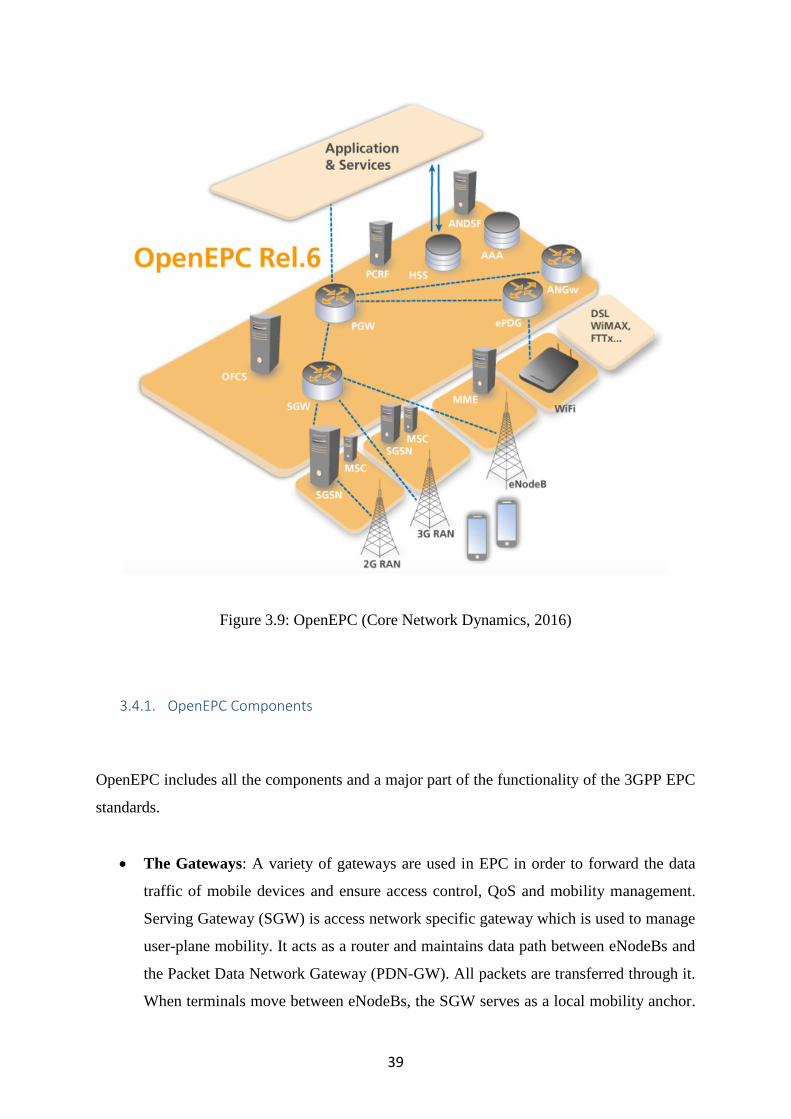
39
Figure 3.9: OpenEPC (Core Network Dynamics, 2016)
3.4.1. OpenEPC Components
OpenEPC includes all the components and a major part of the functionality of the 3GPP EPC
standards.
The Gateways: A variety of gateways are used in EPC in order to forward the data
traffic of mobile devices and ensure access control, QoS and mobility management.
Serving Gateway (SGW) is access network specific gateway which is used to manage
user-plane mobility. It acts as a router and maintains data path between eNodeBs and
the Packet Data Network Gateway (PDN-GW). All packets are transferred through it.
When terminals move between eNodeBs, the SGW serves as a local mobility anchor.

40
The evolved Packet Date Gateway (ePDG) and the generic Access Network
Gateway(ANGW) provide the interconnection with the various Radio Access
Technologies (RATs). The PDN-GW acts as an interface between the EPC and the
packet data networks and routes packets to and from the PDNs. The PDN-GW also
performs a various functions such as allocation of IP-address for UE, QoS enforcement,
policy control and flow based charging. (Firmin, 2016).
The Policy Engine and Control Entities: The policy and Charging Rules Function
(PCRF), the Mobility Management Entity (MME), the Serving GPRS Support Node
(SGSN) and the Access Network Discovery and Selection Function (ANDSF) make
policy based decisions for the connectivity, the access control and the resource
allocated for mobile devices (Core Network Dynamics, 2016).
The Subscription Data Entities: The Home Subscriber Server (HSS) and AAA server
has replaced the Home Location Register (HLR) concepts that used in previous mobile
technologies. HSS is the main subscriber information database that store, update and
transmit notifications on the subscription profile of the users. The AAA server provides
authorization and authentication of mobile devices.
3.4.2. Scalability, Reliability, Openness and Security
OpenEPC integrates with various access network technologies and different services platforms
to provide a complete mobile broadband core network solution. It is available for licensing
with full source code either as a complete testbed or as individual components for research and
development purposes (FOKUS Fraunhofer Institute for Open Communication System, 2010)
The company has recently announced the upcoming release of its OpenEPC 7 software, a
carrier-grade package that now can handle thousands of users per network cell. It includes the
support for LTE-M which is beneficial for the IoT market and the critical communications
features necessary for public safety. According to Carsten Brinkschulte, the CEO of Core
Network, IoT is a key use case for OpenEPC 7, letting mobile operators enhance and extend
their LTE networks at the edge and capitalize on this fast growing market without having to

41
replace their existing infrastructure. “We are delivering on our first public safety contract in
Europe to build a secure, private LTE mess network that aims to put a radio cell running
OpenEPC into vehicles and attach an antenna to the roof, so that every vehicle will effectively
become a mini mobile operator”, said Brinkschulte (Houser, 2016).
Figure 3.10: OpenEPC releases and roadmap (Core Network Dynamics, 2016)
3.5. Amarisoft LTE 100
Amarisoft LTE 100 is a software-based LTE Base Station running on a PC. It is the world´s
first fully software-based LTE Base Station which is more flexible and cheaper than any other
expensive hardware based solution (Amarisoft, 2015). It allows to build a real 4G LTE base
station using a standard PC and a low cost software radio frontend. All the physical layer and

42
protocol layer processing is done in real time inside the PC. So other dedicated LTE hardware
is not necessary (Bellard, 2012).
The Amarisoft core network software is known as LTEMME which is a MME implementation.
It has built-in SGS, PGW and HSS. It can be used with the Amarisoft LTE 100. By combining
LTE 100 with LTEMME, a highly configurable LTE test network can be built. Amarisoft LTE
implements LTE release 8 with Frequency Division Duplexing (FDD) configuration. Core
Network emulation is implemented so that no LTE network infrastructure is needed to use the
base station. It supports test USIM cards using the standard XOR authentication algorithm and
has flexible configuration system to support various LTE parameters. It implements the LTE
PHY, MAC, RLC, PDCP, RRC and NAS layers (George, Sivabalan, Prabhu, & Prasad).
3.5.1. Scalability, Reliability, Openness and Security
Amarisoft LTE is a flexible platform that supports commercial UEs. These commercial UEs
can directly connect to it and access the Internet. All parameters of PHY layer are accessible
through the configuration file. It is possible to test all kind of setups to see how Base Station
and mobile behave in real-time. It is an affordable solution for students and researchers who
can build their own Base Station to work on their project. An LTE base station can be set up
on a PC with lower investment than using traditional hardware. They can instantly compare
theoretical behaviors with the practical one. With Amari LTE 100 stack, the 4G support can be
added to the existing wireless solution in a matter of days. Without heavy investment, anyone
can remain on the top of 3GPP releases and can take the benefit of them (Amarisoft, 2015).
3.6. PhantomNet
PhantomNet is an end to end mobile networking testbed that provides educators and
researchers with a set of hardware and software resources that they can use to develop, debug,

43
and evaluate their mobility ideas. It is a realistic playground where researchers can explore
mobile network architecture in an end to end manner. It is an end-to-end testbed meaning that
it supports experimentation not only with mobile end user devices but also with a cellular core
network that can be configured and extended with new technologies (Banerjee, et al., 2015). It
is based on Emulab, a testbed control suite that has been developed by the Flux Research Group
at University of Utah, USA (PhantomNet, 2016). The researchers and educators from all
around the world can access and share the PhantomNet through the Internet with free of charge.
It provides a single environment where experimenters can combine mobile networking, cloud
computing and software defined networking technologies (Banerjee, et al., 2015).
The PhantomNet consists of diverse mix of hardware and software resources. Users can request
hardware and software resources for their experiment. The hardware components consist of
compute nodes connected by switches, programmable attenuation, off-the-shelf mobile
handsets, and off-the-shelf small cell base stations. For off-the-shelf small base stations, we
can use either ip.access or SDR hardware such as Ettus Research USRP B210. Hardware
resources are connected to a programmatically controlled attenuator matrix to enable controlled
RAN experimentation (PhantomNet, 2016). Software resources available in PhantomNet
include EPC software such as OpenEPC, OpenLTE and Open Air Interface (OAI). OAI
includes SDR-based user equipment (UE) and access point (eNodeB) implementations and an
emerging 3GPP LTE implementation. OpenLTE is similar to OAI but it deals with radio access
layers of LTE only. The OpenEPC, developed by Fraunhofer FOCUS, is the main software
components of PhantomNet. It includes most of the functionality defined by 3GPP LTE version
12 specification (Banerjee, et al., 2015).
Figure 3.11: PhantomNet infrastructure (PhantomNet, 2016)

44
PhantomNet is a flexible platform where we can explore an EPC setup with emulated endpoints
and access points. We can use EPC core software with real, off-the-shelf eNodeBs and UEs. If
we want to experiment both RAN and EPC core, then we can use OAI software. If we do not
like 3GPP EPC core, then it is not necessary to use it. We can use our own clean-slate core
components with OpenLTE (PhantomNet, 2016).
Figure 3.12: Clean-slate mobile network architecture (PhantomNet, 2016)
3.6.1. Scalability, Availability, Openness and Security
Most of the PhantomNet resources are freely available to experimenters worldwide. But
OpenEPC functionality is only available in binary form because of its licensing restriction.
PhantomNet can support different networking setups. It is a flexible platform where various
combinations and configurations are possible. It combines mobile networking, SDN and NFV
which are the key enabler for future mobile network.
PhantomNet continually add more feature and components and makes available for users.
They typically introduce new functionality by providing pre-configured profiles and
accompanying self-help tutorials to get users up and running quickly. As already mentioned,
PhantomNet is based on Emulab. Now it is transforming its classic Emulab interface to web

45
portal. This portal provides easy interface for developing profiles, instantiating and interacting
with experiments (PhantomNet, 2016).
PhantomNet´s OpenEPC components run from disk images with restricted user environments.
User are not given root privilege and can not access to the actual OpenEPC binary components.
They may interact with these components only through control scripts, configuration files, and
service consoles. PhantomNet also set limited privilege for operations such as capturing
network interface traffic and node shutdown/reboot, and disable node console access and
custom image creation operation (Emulab, 2016).
3.7. Software Defined Networking (SDN)
Software Defined Networking (SDN) is an emerging network architecture that allows network
administrator to manage network services through abstraction of lower-level functionality.
This is done by separating the network control plane and data plane enabling the network
control to become directly programmable and the underlying infrastructure to be abstracted for
applications and network services (Open Networking Foundation, 2016). SDN requires some
method for the control plane to communicate with the data plane. OpenFlow protocol is such
a mechanism which is fundamental for building SDN solutions.
Current networks are hierarchical, built with tires of Ethernet switches arranged in a tree
structure. This design is not appropriate to the dynamic computing and storage of today´s
enterprise data centers, R&D departments and Universities (Wikipedia, 2016). Today´s
networks are fragile and difficult to manage. The root of these problems lies in the complexity
of the control and management planes. The increasing number of mobile devices, social
medias, data centers, and cloud computing has strained the capabilities of traditional
networking technologies. With data center and cloud environments, number of end stations
that connect to a single network have grown exponentially. The limitation of MAC address
table sizes and number of VLANs have become difficult to network installation and
deployment. Server virtualization has also caused the scale of networks to increase and this
increased scale has put pressure on layer two and layer three networks as they exist today.
Advances in data center, could computing, mobile communication, and video streaming have

46
caused weaknesses in the current networking technology. This situation has demand for better
ways to construct and manage networks, and that demand has driven innovation of the SDN
(Goransson & Black, 2014).
SDN gives us new ways to design, build and operate networks. SDN method centralizes control
of the network by removing complicated control logic from the device and places into a
centralized controller. This controller is capable of seeing the entire network and able to make
forwarding and routing decisions. It makes decision about how packets should flow through
the network from the data plane. SDN actually attempts to segregate network´s activities
forwarding, filtering, and prioritization. The administrator can change any network switch´s
rules when necessary by prioritizing, de-prioritizing or even blocking specific types of packets
with a very granular level of control. This is especially helpful in a cloud computing
architecture because administrator can manage traffic loads in a flexible and more efficient
manner. Essentially, SDN allows the administrator to use less expensive commodity switches
and have more control over network traffic flow than ever before (Rouse, 2015). By converging
the management of network and applications services into centralized platform, SDN enhances
the benefits of data center virtualization, resource flexibility, and reducing infrastructure costs
and overhead. Common centralized IT policies bring together disparate IT groups and
workflows. As a result, modern infrastructure can deliver new applications and services in a
minutes, rather than days or weeks required in the past. When deploying new applications and
business services, SDN delivers speed and agility. Flexibility, policy, and programmability are
the main properties of SDN solutions, which is capable of handling the most demanding
networking need of today and tomorrow (Cisco, 2016).
All SDN models have some basic components: the SDN Controller as well as southbound
APIs and northbound APIs, SDN Devices, and the applications. The figure 3.13 describes the
operation of the SDN.

47
Figure 3.13: SDN operation overview (Goransson & Black, 2014)
Controller: SDN Controller is the brain of the network which maintains a view of the
the overall network. It is responsible for controlling and presenting an abstraction of
these network resources to the SDN application running above it. The controller allows
the SDN application to define flows on devices and to help the application the
application respond to packets that are forwarded to the controller by the SDN devices.
It also implements policy decisions regarding routing, forwarding, redirecting, load
balancing (Goransson & Black, 2014).
Southbound APIs: Southbound APIs are used to relay information to the switches and
routers.
Northbound APIs: SDN uses northbound APIs to communicate with the applications
and business logic.
Flows: A flow describes a set packets transferred from one network end point to another
endpoint. All packets belonging to that flow have a set of rules which describes the
forwarding actions that the device should decide what to do with each incoming packet.
SDN Devices: SDN device is composed of an API for communication with the
controller. It contains forwarding functionalities for taking appropriate action for each
incoming packet. Flow tables are the fundamental data structure in an SDN device
which allows devices to evaluate incoming packets and take the proper decision. Flow

48
table consists of a number of prioritized flow entries, each of which consist of two
components: match fields and actions (Goransson & Black, 2014). Match fields are
used to compare against incoming packets. If an incoming packet matches the match
fields specified for that flow entry, then the network device should perform appropriate
actions.
Applications: SDN applications are programs that runs above the SDN controller and
communicate their network requirements and desired network behavior to the SDN
controller via the controller´s northbound API. They are responsible for managing the
flow entries that are programmed on the network devices. Other functions that are
performed by SDN applications are load balancing and firewalling. The core
functionality of the application will vary from one application to another, but
application behavior is driven by events coming from the controller as well as external
inputs (Goransson & Black, 2014).
3.7.1. OpenFlow
OpenFlow is a programmable communication protocol that enables the SDN controller to
directly interact with the forwarding plane of the network devices such as switches and routers.
With OpenFlow, the packet moving decisions are centralized, so that the network can be
programmed independently of the individual switches and routers. The concept of SDN came
into existence after OpenFlow appeared on the scene in 2008. So, the arrival of OpenFlow is
the point at which SDN was actually born (Goransson & Black, 2014). The investors of the
protocol consider OpenFlow an enabler of SDN. OpenFlow based SDN architecture is today´s
need for mobile and wireless networks.
OpenFlow was developed and designed to allow researchers to run experimental protocols and
innovate with new protocols in the network we use everyday. A number of network switch and
router vendors have implemented OpenFlow in their products. OpenFlow enabled switches are
now commercially available in the market. Packet forwarding and routing occur on the same
device in a traditional switch but an OpenFlow enabled switch separates the data plane from
the control plane. The data plane resides on the switch itself while a separate controller makes
high-level routing decisions (Wikipedia, 2016). The switch and controller communicate by

49
means of the OpenFlow protocol. The figure 3.14 illustrates the simple architecture of an
OpenFlow solution.
Figure 3.14: General OpenFlow Design (Goransson & Black, 2014).
3.7.2. SDN for Cellular Networks
The growing popularity of mobile devices and broadband mobile network deployment with
LTE /LTE-A have increased mobile data traffic on today´s cellular networks. Mobile and
wireless technologies are growing continuously. As wireless becomes the main option for
people to communicate with others, mobile operators must carry much volumes of traffic and
at the same time provide a number of facilities or services. The increasing number of wireless
technologies 3G, 4G cellular as well as Wi-Fi and Bluetooth are in use simultaneously. To
support these various types of technologies, mobile operator usually has to increase the budgets
required to address the new demands and handle operational headaches. LTE have supported
network operator to maintain the stability of traffic growth by increasing the radio access

50
volume. However, they now face a number of challenges of keeping up with the increasing
demand in their core network (Kabir, A Novel Architecture for SDN-Based Cellular Network,
2014). This is a serious problem for today´s highly centralized cellular network where all the
mobile traffic is handled at central gateways.
The massive growth in mobile data, the need to simultaneously operate over multiple wireless
technologies, and the rapidly evolving mobile services market impose significant challenges
for today´s architecture. OpenFlow-based SDN architecture is suitable for highly scalable
mobile and wireless networks, from access to backhaul and core for addressing these
challenges (Open Networking Foundation, 2013). SDN offers a logically centralized control
plane which enables better coordination among network elements. It can enable common
control protocol across diverse wireless technologies for seamless mobility support within and
across the 3G, UMTS, WiMAX, 4G/LTE, Wi-Fi, and Bluetooth technologies. Due to its
centralized control plane, SDN architecture can give cellular operators greater control over
their equipment and simplify the network management while enabling the network services
(Sebastian, 2015).
Cellular networks need an SDN architecture that handles and manages the full network from a
central location and offers frequent mobility, fine grained measurement, real time control and
at the same time supports many subscribers. The future SDN architecture should address real-
time adaptation scalability challenges that today´s cellular network usually fails (Kabir, SDN
in Cellular Network and Implementatio Challenges, 2016). A simplified SDN-based cellular
network architecture could be represented as shown in Figure 3.15.

51
Figure 3.15: A simplified architecture of SDN-based cellular network (Kabir, SDN in
Cellular Network and Implementatio Challenges, 2016)
The central controller handles and operates all the network control operations. It consists of a
Network Operating System (NOS) running application modules, such as radio resource
management, mobility management, and routing. The SDN controller instructs other
components to operate and forward traffic with the help of these application modules that reside
usually on top of the central controller (Jin, Erran, Vanbever, & Rexford, 2013). OpenFlow
protocol is used to communicate with other networking components.
3.8. Network Function Virtualization
Today´s networks are populated with varieties of physical proprietary hardware appliances.
Service provision within the telecommunication industry has been based on network operator´s
proprietary devices. Due to the proprietary nature of these appliances, it is difficult to bring the
new services into the networks. However, users are demanding more diverse and new services
with high data rates. Therefore, service provider must continuously purchase, store and operate
new physical equipment (Mijumbi, Serrat, Gorricho, & Bouten, 2016). This does not only
increase the cost of energy, and capital investment, but also requires skilled technicians

52
necessary to design, integrate and operate increasingly complex hardware-based appliances.
Therefore, service providers are looking to build more dynamic and service aware networks so
they can deliver new and innovative services to subscribers.
NFV aims to reduces the deployment and operating cost and increases the manageability and
innovation in service space of the network function. It offers a new way to design, deploy and
manage networking services by decoupling the network functions from proprietary hardware
appliances, so that they can run in software (Garg, 2014). The implementation of network
functions through software virtualization can run on an industry standard server hardware, and
that can be moved to, or instantiated in, various locations in the network as required, without
the need for installation of new equipment (Chiosi, Clarke, Benitez, & Damker, 2012). Figure
3.16 illustrates the vision for NFV.
Figure 3.16: Vision for Network Functions Virtualization (Han,
GopalaKrishnan, Ji, & Lee, 2015)
SDN and NFV are complementary approaches. They offer a new way to design, deploy, and
manage the network and its services. But they do not dependent on each other. NFV can be
implemented without SDN. However, two solutions can be combined to create greater value
(Chiosi, Clarke, Benitez, & Damker, 2012).

53
3.8.1. Virtualization of Mobile Core Network
The ETSI has proposed a number use cases for NFV (ETSI ISG, 2013). In this subsection we
will discuss how NFV applicable to EPC, the Core network of LTE. In current EPC, all its
functions are based on proprietary equipment. When a specific function is not available,
operators have to replace existing equipment. Virtualization of EPC can solve these problems
to meet changing market requirements. It could potentially lead to better flexibility and
dynamic scaling, and hence allow mobile operators to respond easily and cheaply to meet
changing market requirements (Mijumbi, Serrat, Gorricho, & Bouten, 2016). The figure 3.17
shows both the normal architecture of LTE and the one in which EPC is virtualized.
Figure 3.17: Virtualization of EPC (Mijumbi, Serrat, Gorricho, & Bouten, 2016)

54
The virtualization of EPC includes MME, HSS, SGW, PGW and PCRF. It allows us to move
toward a more intelligent, resilient, and scalable core architecture and enables flexible
distribution of hardware resources to eliminate performance bottlenecks and rapid launch of
innovative services to generate new revenue sources like M2M and Internet of Things (IoT)
applications (Han, GopalaKrishnan, Ji, & Lee, 2015).
3.9. Cloud Radio Access Network (CloudRAN)
With the growing data traffic in mobile networks and deployment of of 4G/LTE, the current
radio access network becomes dense and heterogeneous. As a result, congestion occurs in RAN
by increasing the number of base stations for user equipment to connect to the base stations.
This denser deployment of BS brings new challenges in interference management and inter
cell coordination that need new approaches to manage (Dawson, Marina, & Garcia, 2014). In
order to handle this scaling capacity and to manage the dense infrastructure, a new architecture
require to tackle interference management and inter cell coordination.
ClouldRAN is a centralized, cloud computing-based architecture for radio access networks that
supports 2G, 3G, 4G and future communication standards (Wikipedia, 2016). CloudRAN uses
virtualization technologies in the radio access networks. As NFV has already emerged as a
viable approach to increase network flexibility for mobile core network, this can be applied to
the radio access part of the cellular network. CloudRAN allows for the use of two principles:
centralization and virtualization of base station (BS) baseband processing in mobile network.
By applying NFV, the network operator can dynamically allocate processing resources within
a centralized baseband pool to different virtualized base stations and different air interface
standards. This allows the operator to efficiently support the variety of air interfaces. In this
case, a base station can be easily built up through the flexible resource combination. The real
time virtualized operating system would adjust, allocate and re-allocate resources based on
each virtualized base station requirements in order to meet its demands (Upperside
Conferences, 2014). By utilizing CloudRAN, operators can centralize the control plane which
brings RAN functionality closer to applications, or further distribute the physical layer closer
to the antenna to enable massive beam forming. Centralizing BS processing with CloudRAN
simplifies network management and enables resource pooling and coordination of radio
resources (Ericsson, 2015). The figure 3.18 shows an examples of functional splits of the radio

55
access protocol layer in a CloudRAN. Therefore, a CloudRAN architecture combines
virtualization, centralization and coordination techniques which are interact with each other
within the network.
Figure 3.18: Functional splits of the radio access protocol layer in a Cloud RAN (Ericsson,
2015)
In current cellular systems, each physical base station (BS) combines baseband processing and
radio functions. With the recent advancements in software defined radios, it is possible to split
the base station into radio front-end and software implementation of baseband processing. With
the CloudRAN, the baseband processing for many cells is centralized. By combing multiple
BSs into a centralized server, CloudRAN improves the performance due to the ability to
coordinate between cells, and also increase the demand for resource control (Beyene, Jantti, &
Ruttik, 2014).
The figure 3.19 illustrates the the architecture of CloudRAN. It replaces the BSs with shared
processing and distributed radio elements. The core components of CloudRAN are: Base
Station Pool, Optical Fronthaul and Remote Radio Heads (RRH). Base station pool provides
signal processing and coordination functionality required by all cells within the area. Optical
fronthaul is a fiber links which carries baseband data and RRHs are light weight radio units
and antennae that user equipment connects to via the RAN. RRHs can be used in anywhere
unlike a traditional base station which requires a mast and housing for the baseband processing
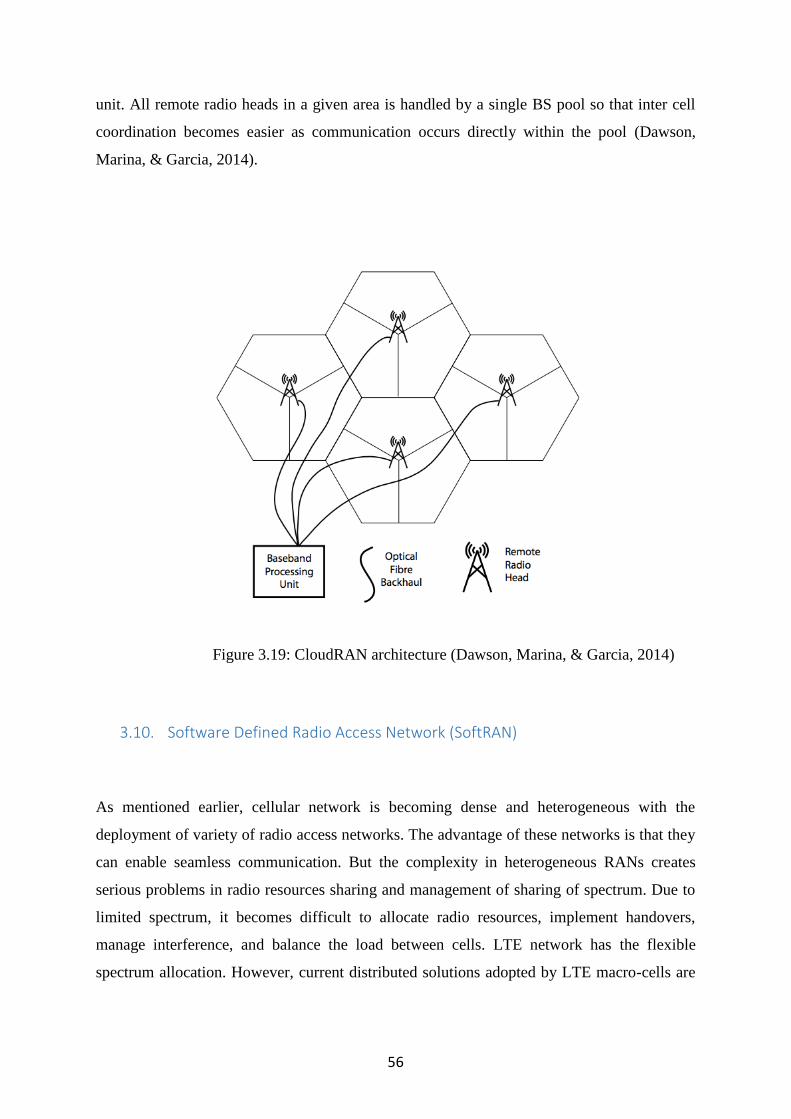
56
unit. All remote radio heads in a given area is handled by a single BS pool so that inter cell
coordination becomes easier as communication occurs directly within the pool (Dawson,
Marina, & Garcia, 2014).
Figure 3.19: CloudRAN architecture (Dawson, Marina, & Garcia, 2014)
3.10. Software Defined Radio Access Network (SoftRAN)
As mentioned earlier, cellular network is becoming dense and heterogeneous with the
deployment of variety of radio access networks. The advantage of these networks is that they
can enable seamless communication. But the complexity in heterogeneous RANs creates
serious problems in radio resources sharing and management of sharing of spectrum. Due to
limited spectrum, it becomes difficult to allocate radio resources, implement handovers,
manage interference, and balance the load between cells. LTE network has the flexible
spectrum allocation. However, current distributed solutions adopted by LTE macro-cells are

57
not scalable for dense small cell deployments (Chen & Nikaein, 2016). A SDN approach for
RAN could be a suitable solution to address the above challenges.
SoftRAN is a software defined control plane for radio access networks that abstracts all base
stations in a local geographical area as a virtual big base station comprised of a central
controller and radio elements (Gudipati, Perry, Erran, & Katti, 2013). The architecture of
SoftRAN is shown in figure 3.20. It has a centralized controller as an alternative to the
distributed control plane currently implemented in LTE networks and control APIs to group
existing cell into CloudRAN like a big base stations. The controller maintains a global view of
the radio access network. The 3D resource grid is an abstraction of radio resource in the
network that offer mapping of resources based on time, frequency and end point as well as
monitoring interference between end points and devices (Dawson, Marina, & Garcia, 2014).
Figure 3.20: SoftRAN architecture (Gudipati, Perry, Erran, & Katti, 2013)
SoftRAN mainly focusses on balancing the loading of cells through its logically centralized
control plane. Through the global view of network, a big base station can manage interference,
load, quality of services, smooth handover and also improve utility and power usage (Gudipati,
Perry, Erran, & Katti, 2013).

58
3.11. Machine to Machine (M2M) Communication
Today´s communication network is focused on human communications such as voice call,
messaging and Internet browsing. As IPv6 system is already rolled in, every device on the
Internet can have its own IP address. Cisco Internet Business Solution Group (IBSG) predicts
that the number of connected devices will reach over 50 billion by 2020 (Cisco IBSG, 2011).
As a result, M2M communication has emerged to address new kinds of services and
technologies and is expected to be the next revolution in the mobile communication.
In M2M communication, machines autonomously communicate with each other without
human interfacing or interaction. In addition to exchanging data, it allows devices to monitor
systems themselves and automatically respond to changes in the environment, with much
reduced need for human involvement. Three very common technologies: wireless sensors, the
Internet and server computers are coming together to create M2M communication (Crosby,
2016). With M2M technology, it is possible to create a common network of communication
among all physical devices around us. M2M is an inevitable part of Interne of Things (IoT)
technology, which is expected to be the next revolution in the mobile communication
technology (Nokia, 2015). With the rise of IoT, M2M communications has become a driving
force for innovation in cities, homes, cars, and workplace. It has the power to reinvent the
business and turns remote objects into intelligent assets (Vodafone, 2016).
3.11.1. How M2M Works
In M2M communications, a remote sensor attached with device gathers data and sends it
wirelessly from a SIM integrated in the device to a central server where it is translated into
meaningful information, for example, as shown in figure 3.21. At that point, the data is
analyzed and acted upon, according to the software in place (Crosby, 2016).

59
Figure 3.21: ETSI M2M Network architecture (Corici, Coskun, Mao, Kurniawan, & Wahle,
2012)
The data transfer patterns in the M2M communication is different from current mobile
communication system. In order to be able to fully use machine type communication (MTC)
which permits the deployment of novel machine-oriented services, a set of challenges have to
overcome. ETSI has defined a set of requirements to achieve an efficient end to end delivery
of the services. Many M2M applications will need to deliver and process information in real
time or near real time and many nodes will have to be extremely low power or self powered
device. The communication of the devices and the network core should be secured against a
large variety of security threats. In order to be able to manage the overall system, the M2M
system should include a middleware layer which facilitates the communication between the
devices and network application. Likewise, MTC applications can send receive packet
switched data only during defined time interval. Based on these general requirements, ETSI
has developed M2M middleware architecture which is the basis for further development of
M2M applications (Corici, Coskun, Mao, Kurniawan, & Wahle, 2012). Now MTC has become
an important part of the infrastructure of LTE which connects all other new technologies in
mobile communications. This aims to increase the level of system automation in which device
can exchange and share data, addressing requirements and challenges of the emerging world
of Smart cities and the Internet of Things.
60
3.11.2. OpenMTC
OpenMTC has been designed by Frauhofer Institute FOKUS and Technische Universitat
Berlin as an open source software which provides test environment for Machine Type
Communication. It is a middleware platform which resides between packet core network and
applications and implements specific M2M service capabilities such as generic
communication, application enabling, and remote management (Technische Universitat Berlin,
2015). OpenMTC helps academia and industry to integrate various machine devices and
applications into a single local testbed, so that they can focus on research and development of
M2M systems without constructing a real system, which ultimately reduces the development
cost.
OpenMTC platform has been designed to act as a middleware between application domain and
M2M area Network, inspired by ETSI M2M, oneM2M and Open Mobile Alliance (OMA)
standards as shown in figure 3.22 (Corici, Coskun, Mao, Kurniawan, & Wahle, 2012).
OpneMTC mainly consists of three components: M2M Network Area, M2M capabilities
layers, and application domains. Devices are located in M2M Network Area and are connected
through a variety of networks infrastructure such as ZigBee, Wi-Fi, GPRS, FS20, and
Bluetooth. Two common M2M capability layers are: a gateway service capability layer
(GSCL) and a network service capability layers (NSCL). The GSCL connects the devices
located in Network Area with the server where as NSCL mediates the interactions between
applications in the M2M network area (Abdurohman, Sasongko, & Herutomo, 2015).

61
Figure 3.22: OpenMTC architecture (Corici, Coskun, Mao, Kurniawan, & Wahle, 2012)
OpenMTC platform as a middleware has an ability for handling thousands of sensors,
actuators and M2M applications. OpenMTC has capabilities to support interworking with other
telecommunication cores, such as the IMS and EPC. Translating the information exchanged
from sensors and devices into SIP messages enables the usage of IMP for various M2M
applications. This means the M2M communication rely on the security and reliability of IMS.
OpenMTC relay on OpenEPC for connectivity selection management and carrier grade Quality
of Service, as EPC provides advanced networking capabilities such as policy and charging
control. Therefore, OpenMTC helps to be prepared for the upcoming all-IP NGN and M2M
world using open and vendor independent testbed infrastructure (Fraunhofer FOKUS, 2012).

62
4. Open Air Interface
This chapter gives a brief introduction of OpenAirInterface and describes it as a reference
platform for innovation in the field of 4G/5G. It also describes how to install and configure
OpenAirInterface on a Linux-based PC.
4.1. Introduction
Cellular data traffic has exponentially increased in recent years due to the rapid adaptation of
Internet connected mobile devices such as smart phones, tablets, and other M2M devices. As
cellular technology offers variety of services and uses different type of topology, it ultimately
makes network more complex and costly to deploy, operate, maintain and upgrade. While 4G
LTE networks have been already deployed worldwide, research for the next generation mobile
networks have been begun by EURECOM using open source software called OpenAirInterface
(OAI).
OpenAirInterace is an open source based experimentation and prototyping platform created by
the Mobile Communication Department at EURECOM, a France based research institute, to
enable innovation in the area of mobile/wireless networking and communication (Nikaein, et
al., 2014). Researchers can rapidly prototype and test systems using OAI which would be
infeasible with proprietary equipment. Prior to the development of OAI, 4G LTE was too
complex and esoteric technology for a community of open source developers to manage. OAI
is an open forum that aims on improving the emerging industrial air interface standards such
as LTE and 5G regarding spectral, algorithmic and protocol efficiency research (Ravali,
Vasudevan, & Sundaram, 2016). EURECOM believes that OAI can be useful in the
development of the 5G technologies research like M2M communication, CloudRAN,
Heterogeneous Cellular Networks and Device to Device (D2D) communication, Shared
Spectrum, Millimeter Waves, and Software Defined Mobile networks (Nikaein, et al., 2014).

63
OAI offers an open-source software-based implementation of the LTE system spanning the full
protocol stack of 3GPP standard both in E-UTRAN and EPC (OpenAirInterface, 2016). It can
be used to build and customized an LTE base station and core network on a PC and connect a
commercial UEs to test different configurations and network setups and monitor the network
and mobile device in real time. OAI is based on a PC hosted software radio frontend
architecture (Nikaein N. , 2015). With OAI, the transceiver functionality of a base station,
access point, mobile terminal, core network etc. are realized via a software radio front end
connected to a host computer for processing. OAI provides a rich development environment
with a range of built-in tools such as highly realistic emulation modes, soft monitoring and
debugging tools, protocol analyzer, performance profiler, and configurable logging system for
all layers and channels (OpenAirInterface, 2016). EURECOM has recently created the
OpenAirInterface Software Alliance(OSA) with the aims of providing an environment for
EUTRAN and the EPC of 3GPP cellular systems to interoperate with the closed source
equipment in both part of the network.
4.2. OAI Components
The OAI consists of two main components of the LTE system architecture: the radio part, the
E-UTRAN and the core part, the EPC. The transceiver part i.e. a base station, access point and
mobile terminal is achieved by using Software Define Radio. The EPC core part is an OpenEPC
elements i.e. SGW, PGW, MME, HSS etc. It is said that OAI is the only SDR based solution
that is fully open source and provides a complete software implementation of all elements of
4G LTE system architecture. OAI equipment is the combination of software and hardware
platforms. Besides the real-time operation over hardware components, OAI can be run on
emulation mode too.
4.2.1. Software Platform
The OSA´s software packages for core network is known as openairCN while the access
network software for base stations and terminals goes under the name of openair5G. The core

64
part can be integrated with other open source software packages such as openIMS, Clearwater
IMS, OpenDayLight etc. on a generic cloud computing platform OpenStack. In order to ease
with integration within an OpenStack environment, openairCN is distributed under an Apache
V2.0 license. On the other hand, openair5G is freely distributed by the OSA under the terms
stipulated by a new open-source license, the OAI Public License, catering to the intellectual
property agreements used in 3GPP and allowing contributions from 3GPP members holding
patents on key procedures used in the standard (Knopp, 2016). The combination of these two
sets of software packages currently includes a standard compliant implementation of a subset
of Release 10 LTE for UE, eNB, MME, HSS, SGW, and PGW on standard Linux-based
computing equipment. At the physical layer, it provides the following feature (Nikaein N. ,
Latency, Cooperation, and Cloud in Radio Access Network, 2015):
LTE release 8.6, with a subset of Release 10;
FDD and TDD configuration in 5, 10, and 2o MHz band-width;
Transmission mode: 1 (SISO), and 2, 4, 5, and 6 (MIMO 2x2),
CQI/PMI reporting;
All DL channels are supported: PSS, SSS, PBCH, PCFICH, PHICH, PDCCH, PDSCH,
PMCH;
All UL channels are supported: PRACH, PUSCH, PUCCH, SRS, DRS;
HARQ support (UL and DL),
Highly optimized baseband processing (including turbo decoder).
For the E-UTRAN protocol stack, it provides:
LTE release 8.6 and a subset of Release 10 features;
Implements the MAC, RLC, PDCP and RRC layers;
Protocol service for Release 10 eMBMS (MCH, MCCH, MTCH)
Priority-based MAC scheduler with dynamic MCS selection;
Fully reconfigurable protocol stack;
Integrity check and encryption using the AES and Snow3G algorithms;
Support of RRC measurement with measurement gap;
Standard S1AP and GTP-U interfaces to the Core Network;

65
IPv4 and IPv6 support.
Features of OAI EPC implementation include:
SGW, PGW, MME and HSS implementation;
NAS integrity and encryption using the AES and Snow3G algorithms;
UE procedures handling: attach, authentication, service access, radio bearer
establishment;
Transparent access to the IP network- no need of external SGW and PGW;
IPv4 and IPv6 support.
Figure 4.1: OpenAirInterface LTE software stack (Nikaein, et al., 2014)
Figure 4.1 shows the entire LTE protocol stack in OAI. The OAI can be used with a rich
software development environment including Aeroflex-Geisler LEON/GRLIB, RTAI, Linux,
GNU, Wireshark, control and monitoring tools, message and time analyzer, low-level log
processing, traffic generator, profiling tools and soft scope (Nikaein, et al., 2014). It also
provides tools for protocol validation, performance evaluation and pre-deployment system test
(OpenAirInterface, 2016).

66
4.2.2. Hardware Platform
The OAI equipment consists of two types of hardware components: CardBus MIMO and
Express MIMO. The CardBus MIMO is a software defined radio. USRP B210 platform is
widely used software radio frontend in research community. The OAI supports the USRP
Hardware Driver (UHD) for use with the recent version of USRP PC-hosted software radio
platform (Nikaein, et al., 2014). Express MIMO is a default software radio frontend for OAI.
It is a baseband processing board for high performance radio signal processing. It uses a
standard PCI-express interface which can be controlled through PC. Currently newer version
ExpressMIMO2 is available in the market. The embedded system on the ExpressMIMO2 is
based on a LEON3 microcontroller. The LEON3 has a large DDR3 memory for data and
program storage. The embedded software for the FPGA is booted via the PC or can reside
entirely in the boot ROM which is part of the FPGA design. In the current design, the embedded
software is booted by PCIexpress dynamically under control of the PC device driver
(EURECOM, 2016).
The OAI platform can be used in several different configuration including commercial
components to varying degrees (Nikaein, et al., 2014):
OAI UE <--> OAI eNB + OAI EPC
OAI UE <--> OAI eNB + Commercial EPC
OAI UE <--> Commercial eNB + OAI EPC
OAI UE <--> Commercial eNB + Commercial EPC
Commercial UE <--> Commercial eNB + OAI EPC
Commercial UE <--> OAI eNB + Commercial EPC
Commercial UE <--> OAI eNB + OAI EPC
4.2.3. Emulation Platform
Besides the real time operation and simulation of OAI software over the hardware components,
the full protocol stack can be run in a laboratory environment in emulation mode. It is a next

67
generation framework for real time wireless 4G systems and networking experimentation
applicable to evolving cellular technologies such as LTE-Advanced. The objective of this
platform is to fill the gap between the simulation and real experimentation by providing the
baselines for protocol validation, performance evaluation and pre-deployment system test
(EURECOM, 2016).
Figure 4.2: OAI Platforms (EURECOM, 2016)
4.3. OAI Towards 5G Research
The fifth generation of mobile network is going to support a wide range of new applications
and services, which demands higher data rate, reduced energy consumption per service, reliable
connectivity with very low latency and the possibility to handle extreme device densities. As
LTE gradually deployed worldwide, cellular system is still slow in moving towards this
direction thus locks to expensive HW/SW platforms (Yeoh, Mokhtar, Rahman, & Samingan,
2016). However, with the help of OAI, we can build and support an open cellular ecosystem
that can use the commodity hardware or general purpose processor for open LTE system for
future 5G. RAN virtualization or CloudRAN, SDN and NFV are the solutions to avoid the

68
costly deployment, operation and maintenance of future mobile network. In this regard, the
OAI, an open source base LTE implementation is definitely speeding CloudRAN, SDN, and
NFV and also realizing the possibility of low cost LTE network deployment in future (Virdis,
Iardella, Stea, & Sabella, 2015).
The concept of CloudRAN evolved from a distributed base station (DBS) architecture where a
BS server is responsible for baseband processing (Hossain & Hasan, 2015). In CloudRAN,
functions of eNBs is split into two main parts: radio access part called Remote Radio Head
(RRH) which is deployed in the territory generally according to coverage policies and base
band function called Base Band Unit (BBU) that can be centralized and remotely connected
with the RRH (Virdis, Iardella, Stea, & Sabella, 2015). A BBU pool serves a particular area
with a number of RRH of macro and small cells. Based on baseband signals received from the
cloud, the transmissions of radio signals to users are performed The emulation mode is
designed for experimentation in wireless access technology in a real network setting. This
emulation environment can help the researchers to experiment their ideas quickly and verify
them in a realistic environment. The current development targets generic Linux-based
hardware environment ranging form a single PC to sophisticated cluster or even a GPU
workstation (Romdhanne, Nikaein, Knopp, & Bonnet, 2011). It provides a complete wireless
protocol stack and implements the PHY, MAC, RLC, PDCP, RRC, as well as providing an
IPv4/IPv6 network device interface under Linux (Anouar, Bonnet, Câmara, Filali, & Knopp,
2008). It has different modes of operation including single machine and multi-machine
emulation. The single machine mode is the virtualization of network nodes in a single machine
while the multi-machine emulation is distributed deployment on a local network to transmit
information via the IP address. For the PHY layer of the platform, it has two operating modes:
full PHY layer and PHY abstraction. The Full PHY layer mode which is more detailed and
intensive involves convolution by the RRHs (Hossain & Hasan, 2015).

69
Figure 4.3: An LTE-A system enhanced with cloud-based radio access network (Hossain &
Hasan, 2015)
The radio and baseband processing functionality is integrated inside the BS in LTE-A based
cellular system and the inter-BS communication is performed over X2 interface. In CloudRAN,
as shown in figure, the baseband processing is performed in the cloud (e.g. BBU pool). A BBU
pool is a virtualized server which can consist of general-purpose processors to perform
baseband processing (Hossain & Hasan, 2015). Figure 4.3 shows an example of a CloudRAN
mobile LTE network. The fronthaul part of the network spans from the RRHs sites to the BBU
Pool. The backhaul connects the BBU Pool with the mobile core network. At a remote site, the
radio unit e.g. RRH is co-located with the antennas and performs digital processing, digital to
analog conversion and performs digital conversion, power amplification and filtering (Checko,
et al., 2015). This approach provides several research opportunities. Centralization of access
network processing will allow the implementation of smart algorithms for cooperation among
the base stations in terms of radio resource allocation, QoS-aware traffic management and
power saving (Virdis, Iardella, Stea, & Sabella, 2015).
CloudRAN will enhance the scalability, improve network capacity, and extend the coverage of
future 5G systems. In order to carry out research on these topics, we need a software platform

70
capable of emulating cellular network on general purpose hardware. Due to its emulation
capacity, OAI appears to be the most promising and complete project for 5G research which
allows one to conduct performance evaluation campaigns on LTE networks with a protocol
stack entirely implemented in software. In addition, OAI allows one to carry out experiments
using hardware equipment and commercial terminals, by ensuring real-time performances,
validation and prototyping (Virdis, Iardella, Stea, & Sabella, 2015). Thus, the OAI is a suitable
platform for an open cellular ecosystem both for 4G experimentation and 5G research.
4.4. OAI Installation
This section describes installation of OAI on a Linux-based PC as well as materials and
methods required for installation.
4.4.1. Building, Installing, and Running OAI
The OpenAirInterface software consists of two main components of LTE system Architecture:
the radio part, the E-UTRAN and the core part, the EPC part. The EURECOM´s access network
software is known as openairinterface5G while the EPC software goes under the name of
openairCN. The transceiver part (a base station, access point, mobile terminal) is achieved by
using USRP SDR. The EPC part is a bundle of software components that provides the MME,
SGW, PGW and HSS functions of the LTE core EPC architecture.

71
Figure 4.4: EURECOM core network entities overview (Bonnet, et al., 2016)
The MME is a network entity that can be deployed on its own host or can be co-located with
any other LTE network entity such SPGW and HSS. But the EURECOM does not recommend
the deployment of MME on a eNB even it works. The SPGW can be deployed on its own host
or can be co-located with MME or/and with the HSS (Bonnet, et al., 2016). In a deployment
scenario that I followed, there is no S5 and S8 interface as SGW and PGW are merged together.
The EURECOM eNB software comes with bundle of components that provides the eNB
functions of the LTE on both radio interface i.e. Uu and the core network interfaces i.e. S1-C
and S1-U. There are several deployment scenarios with the EURECOM eNB and UE. The
figure 4.5 shows OAI eNB with S1 interface which describes a EURECOM eNB and EPC
providing MME and GW functions, and interact with the EURECOM HSS. In this
configuration, the S11 interface is virtual in the sense that S11 messages do not go through the
network layer but through an inter-task interface message passing middleware (ITTI) (Gupta,
et al., 2015).

72
Figure 4.5: OAI eNB with S1 interface (Gupta, et al., 2015)
Several prerequisites are required before the system will be capable of building, installing, and
running OAI software.
4.4.1.1. Hardware Components
EURECOM software currently supports Intel architecture based PCs for the eNodeB or UE
targets. The software has been tested on Intel Core i5 and i7 processors. The operating system
requires for these software is Ubuntu 14.04 LTS (32-bit or 64-bit). According to EURECOM,
the OpenairCN EPC component should work on any 64 bits Linux machine.
The USRP B210, which acts as a transceiver, is a key component that makes OAI possible.
The Express MIMO2 is a baseband processing board for high performance radio signal
processing. It uses a PCI express interface which can be controlled through PC. For real time
operation, these hardware targets have some constraints (EURECOM, 2015).
ExpressMIMO2 PCIe card requiring a PC with a free 8/16-way PCIe slot.
USRP B210 USB3 radio card requiring a PC with a free USB3 port.
Ethernet transport requires a PC with a fast Ethernet port (10G or more).

73
4.4.1.2. Kernel Requirements for RAN
The openairCN does not require any special kernels and we can generally use Ubuntu
distributions with generic kernels. The EURECOM currently supports Ubuntu14.04 LTS and
Ubuntu 15.04 with a generic 3.19 kernel. But for openairinterface5G, we should install low-
latency kernel. Currently OAI supports 14.04 LTS with a recent low-latency kernel 3.19.0-61-
lowlatency. If someone wants to run OAI core network software on the OAI eNB, then a low-
latency kernel is required. There are some other options we need to follow before the actual
installation begins. We should disable the C-states from BIOS in order to reduce the processor
power when not needing the full speed. Another option is disabling CPU frequency scaling
which enables the operating system to scale the CPU frequency up and down in order to save
power. A detail description about kernel requirements for OAI is given in Appendix 1.
4.4.1.3. Getting the Code
The OAI software can be obtained from EURECOM gitLab server. Before downloading the
code, we need to install a modern version of subversion/git by executing the following
command.
sudo apt-get update
sudo apt-get install subversion git
The EURECOM openairinterface5G (RAN) repository has source code for eNB RAN and UE
RAN. The core network source code is placed in openair-cn repository. If someone wants to
check in code to git server, then he needs to configure git with his name/email address. In order
to get code, we need to add a certificate from www.gitlab.eurecom.fr to our Ubuntu 14.04
installation machine. The user can checkout the git repository by using following commands.
Checkout RAN repository (eNodeB RAN + UE RAN):
git clone https://gitlab.eurecom.fr/oai/openairinterfac5g.git
Checkout EPC repository:

74
git clone https://gitlab.eurecom.fr/oai/openair-cn.git
By default, we are on the master branch which is most stable branch. The develop branch
contains recent commits that are tested on OAI test bench.
4.4.1.4. Building the Code
Now we have two folders: openair-cn and openairinterface5g in our home directory. We use
an automated build script located at the cmake-targets directory to build OAI eNodeB, EPC
and HSS. The cmake tool automatically generates makefiles to build the system for OAI.
Building Script for openairinterface5g
cd ~/openairinerface
source oaienv # It sets the correct environment variables.
cd cmake_targets
. /build_oai –I –g –eNB –x --install-system-files –w USRP --install-optional-packages
(this command is for USRP)
. /build_oai –I –g –eNB –x --install-system-files –w EXMIMO --install-optional-
packages
(this is for EXMIMO RF)
. /build_oai –I –g –eNB –x --install-system-files –w BLADERF --install-optional-
packages
(this is for BladeRF)
We can use the . /build_oai –h option to understand the meaning of different options used in
the above commands. Some of them are summarized as follows.
-I: installs required packages.
-g: adds debugging symbols to compilation directives.
--eNB: installs eNB, i.e.; Lte-softmodem.
-x: adds a software oscilloscope feature to the produced binaries.

75
--install-system-files: installs OAI required files in Linux system.
-w: adds the hardware support, which is USRP in my case.
--install-optional-packages: Installs optional packages (EURECOM, 2016).
Building script for openair-cn
cd openair-cn
cd SCRIPTS
. /build_mme –i
. /build_hss –i
. /build_spgw –i
By default, we are on master branch. To change to develop branch, we need to use two more
command after we are on openair-cn directory: git checkout develop and git pull.
4.4.1.5. Configuration
Basically there are two types of setup for OAI software: The first method is setting up OAI
eNB, EPC and HSS on a single host and the second method is running OAI eNB and EPC plus
HSS on different hosts. The building procedure is same for both types of setup, but
configurations are different. Because of some unexpected real-time issues, the EURECOM
recommends the second type of setup. Here I explain the setup for running eNB and EPC plus
HSS on two different hosts.
The IP address of the PC which has eNB installed is 129.241.209.200 and the PC which has
EPC + HSS is 129.241.208.190. Both the PCs are connected together with the Ethernet (eth0)
interface.
In eNB configuration file, we need to change some network parameters like tracking area code
(TAC), mobile country code (MCC), mobile network code (MNC), IP address of MME and
eNB related network interface information. The eNB configuration file is located at the
following directory: ~/openairinterface5g/targets/PROJECTS/GENERIC-LTE-
EPC/CONF/enb.band7.tm1.usrpb210.conf.

76
tracking_area_code = "1";
mobile_country_code = "208";
mobile_network_code = "93";
mme_ip_address = ({ipv4 = "129.241.208.190";
NETWORK_INTERFACES:
{
ENB_INTERFACE_NAME_FOR_S1_MME = "eth0";
ENB_IPV4_ADDRESS_FOR_S1_MME = "129.241.209.200/23";
ENB_INTERFACE_NAME_FOR_S1U = "eth0";
ENB_IPV4_ADDRESS_FOR_S1U = "129.241.209.200/23";
ENB_PORT_FOR_S1U = 2152; # Spec 2152
};
In the above code, mme_ip_address is network interface´s IP address of EPC/HSS and
NETWORK_INTERFACE is the eNB related network interface information. A brief overview
of all configuration file for OAI is shown in appendix
By default, OAI SQL database password is ´linux`. We can provide our own password during
installation. In that case we need to change the password option in configuration file. The
operator key for oai_db.sql must match to that of UE SIM card´s operator key. The appendix
5-2 shows all the configuration related to EPC machine.
4.4.1.6. Compiling and Running eNB, EPC and HSS
Before running OAI components, we need to install HSS and MME certificates into a directory
/usr/local/etc/oai/freeDiameter as follows:
cd ~/openair-cn/SCRIPTS

77
./check_hss_s6a_certificate /usr/etc/oai/freediameter/ hss.openair4G.eur
./check_mme_s6a_certificate /usr/etc/oai/freediameter/ shyamalpc.openair4G.eur
After installing, we always need to run HSS first and then after EPC is connected to HSS we
need to compile and start the eNB.
Compile and run HSS:
cd ~/openair-cn
cd SCRIPTS
./build_hss –c
./run_hss - i ~/openair-cn/SRC/OAI_HSS/db/oai_db.sql # this command needs to run
only once which install the OAI database.
./run_hss # this command for all other subsequent runs
Compile and Run MME:
cd ~/openair-cn
cd SCRIPTS
./build_mme –c
./run_mme
Compile and Run SP-GW:
cd ~/openair-cn
cd SCRIPTS
./build_spgw –c
./run_spgw -r
Compile and Run eNB:
cd ~/openairinterface5g
source oaienv
./cmake_targets/build_oai –w USRP –x c --eNB
cd cmake_targets/lte_build_oai/build
sudo –E ./lte-softmodem –o $OPENAIR_DIR/targets/PROJECT/GENERIC-LTE-
EPC/CONF/enb.band7.tm1.usrpb210.conf –d

78
4.4.1.7. UE configuration and User Registration on HSS Database
For user registration on HSS database, the UE or USIM card must have the following
information.
MCC: 208
MNC: 93
TAC: 1
IMSI:208930000000001
Ki: 8BAF473F28FD09487CCCBD7097C6862
OP (Operator Key): 11111111111111111111111111111111
The operator key in hss.conf file must be matched with SIM card´s OP key. To configure UE,
we have to create an Access Point Name (APN) profile in our smartphone. The required fields
in APN are name, APN, and bearer.
We need to register the user on HSS database to complete the UE attached procedure. For this
purpose, we have to add user to oai_db.users table and have to update oai_db.mmeidentity and
oai_db.pdn tables with necessary parameters. We can check out existing users in the database
via phpmyadmin. However, we can not be able to insert a user record on phpmyadmin, because
authentication key Ki as well as Operator key OPc are stored as binary in the database. For this
purpose, we can use mysql –u root –p command from terminal and the password is ´linux´.
The SQL commands that are used to add user to table oai_db.users and updating
oai_db.mmeidentity and oai_db.phd tables are shown in Appendix 7.
4.4.2. Materials and Methods
The OAI team provides a lot of informations and tools required for implementing OAI
software. Some of them are: git repository, twiki site, mailing lists, bulletin board forum and
Bugzilla (EURECOM, 2016).

79
OAI Git Repository: The OAI software can be obtained from git server hosted by
EURECOM. Normal user can obtain code without login to the git server but for
developer who wants to commit in code must login with user account.
OAI Mailing Twiki: This contains practical information on software installation,
machine configuration, code compilation and many more. This website is no longer
maintained now, but it is still useful for lot of information. The new wiki is now
available at EURECOM gitlab server.
OAI Mailing Lists: Several mailing lists for developers and users are hosted on
EURECOM´s sympa server. For example, openair5g-user is for the users of
OpenAirInterface and openair5g-devel is for the developers of OpenairInterface.
Similarly, openaircn-user is for the user of OpenairCN and openaircn-devel is for the
developers of OpenairCN.
OAI Forum: This is created for communication between developers and people
curious about what is going on in EURECOM. This can be considered as a direct
information exchange.
OAI Bugzilla: This is created for reporting bugs but it is not used.

80
5. Results and Discussion
This chapter presents the results of my analysis. The first section describes the results obtained
from analysis of each of open source mobile communication software. The second section
describes the results obtained from the implementation of OpenAirInterface. Section 5.2
summarizes the thesis and discusses its findings.
5.1. Results
The results obtained from the study of open source mobile communication software show that
they are quite useful for experimentation and testing of new generation of mobile
communication architecture. They provide a significant opportunity for students and
researchers to interact with next generation telecommunication architecture. In the past,
projects OpenBTS and OpenBSC were considered as fun lab projects, but now companies
scaled and released the commercial version. These open source GSM projects allow very rapid
and economical deployment of GSM in rural of developing countries.
As LTE is a new wireless technology, OpenEPC can be used to create NGMN testbeds which
are used to prototype, test, and perform research and development of NGMNs. It integrates
various network technologies and application into a single testbed. The upcoming release of
OpenEPC7 includes the support for LTE-M which is beneficial for IoT market. Another LTE
project called Amarisoft LTE100 is the world´s first fully software based LTE Base Station
which is more flexible and cheaper than other hardware based solution. The researchers and
educators from all around the world can access and share PhantomNet Project through the
Internet with free of charge, where they develop, debug and evaluate their mobility ideas.
The current cellular system is still slow and requires expensive HW/SW platforms. CloudRAN,
SoftRAN, SDN, and NFV are the solutions to avoid the costly deployment, operation and
maintenance of future mobile networks. CloudRAN and softRAN will enhance the scalability,
improve the network capacity, and extend the coverage of future 5G systems. Future cellular
networks nee an SDN which can handle and manages the network from the central location

81
and offers mobility and control. The results obtained from the installation of OAI is described
in next sections.
5.1.1. OAI Experimental Testbed
As illustrated in figure 5.1, the OAI experimental testbed consists of OAI eNB installed in one
machine and OAI EPC (MME, HSS and SPGW) installed in another machine. USRP B210 is
connected with eNB machine for radio interface. Both the machines run Ubuntu 14.04 LTS in
Intel x86-64 machines comprising 4 cores with Intel i7 processor core at 2.80GHz. The OAI
EPC is connected with OAI eNB using Ethernet interface. The USRP B210 is connected with
eNB through USB 3.0. The Samsung Galaxy S3 with EURECOM provided SIM card acts as
UE.
Figure 7.1: OAI experimental setup

82
Both EPC and HSS run successfully. After EPC is connected with HSS, we can see both enter
STATE_OPEN from the terminal as shown in Appendix 8-4. The eNB is also successfully
connected and shows something like the following in the figure 5.2 on eNB terminal.
Unfortunately, eNB starts to crash after sometime due to some real time issues with USRP
B210.
Figure 7.2: eNB successfully connected before crash

83
5.1.2. Real Time Issues
Unfortunately, eNB is not associated with MME because of some real time issues. It happens
because eNB installed computer does not send data to USRP B210 fast enough. That means
data transfer is not happing in real-time. According to the OAI team, this problem is radically
improved in the upcoming merge from “enhancement-10-harmony” branch. Appendix 8-1
shows some unwanted character eNB crashed due to real time issues with USRP B210. From
this experiment we can say that OAI software is not yet mature and still have some issues.
5.2. Discussion
Based on the above results, we see that open source projects have shown the feasibility of using
open source components and low cost hardware platform to deploy GSM and LTE testbeds.
By breaking the boundary of proprietary and closed systems, open source projects not only
reduce the cost but also boost the innovation in the field of mobile communication networks.
Open source GSM Projects such as OpenBTS and OpenBSC have been improved with the aims
of taking them out of the lab and into the commercial world. They are already being
implemented in rural areas of developing countries. The latest release of these projects offers
significant improvements in processing capacity and system management features. They are
highly scalable, reliable, secure and easy to use.
Open LTE projects such as OpenEPC, Amarisoft LTE 100 and PhantomNet are useful for
testing and research the advanced features of EPC/LTE. The upcoming release of OpenEPC 7
supports LTE-M features which is beneficial for M2M communication. It integrates well with
OpenIMS core and provides a complete mobile broadband core network solution. It is also
possible to combine OpenEPC, Amarisoft LTE 100 and PhantomNet together and provides a
complete end-to-end mobile networking testbed for educators and researchers where they can
develop, debug and evaluate their mobility ideas.
Unfortunately, I could not implement OAI software completely due to some real time issue
with USRP B210. But I think OAI can be instrumental in the development of key 5G
technologies like CloudRAN, SDN, NFV, massive MIMO and M2M/IoT. These technologies

84
are the solutions to avoid the costly deployment, operation and maintenance of future mobile
networks.
5.2.1. Answering Research Questions
This section answers the research questions as mentioned in section 1.1.1.
1. What are the State of Art approaches to investigate and analyze the available
open source mobile communication software?
There are several open source projects works in the field of mobile communication.
Chapter 3 discusses some of the available open source projects. Section 3.1
describes about OpenBTS projects which is considered as an open cellular
ecosystem. As OpenBTS is SIP based network, there are possibilities of integration
with next generation mobile networks. Section 3.2 discuses about OpenBSC which
was originally developed for research and experimentation, but now it has been put
to use in real world applications. The openIMS core is discussed in section 3.3
whose purpose is to provide IMS core reference implementation for IMS
technology testing. It can be integrated with cloud computing and now it is evolved
as the core signaling architecture of Next Generation Networking (NGN) for
multimedia services. Similarly, section 3.4 explain about OpenEPC which can be
used to create Next Generation Mobile Networks (NGMNs) which are used to
prototype, measure, monitor, test and perform research and development for
NGMNs. Section 3.5 describes about Amarisoft LTE 100 which is a software based
LTE Base Station and section 3.6 discusses about PhantomNet project. The
PhantomNet is an end to end mobile networking testbed which provides a single
environment where experimenters can combine mobile networking, cloud
computing and software defined networking technologies. Finally, section 3.9 to
section 3.11 as well as chapter 4 discusse how OpenAirInterface combine with
Software Defined Network, Network Function Virtualization,
CloudRAN/SoftRAN and Machine to Machine communication revolutionized next
generation mobile communication networks.

85
2. How to evaluate usability, easiness of installation, portability, scalability,
reliability and openness of these open source mobile communication
software?
The evaluation of open source mobile communication software in terms of
usability, portability, scalability, reliability, easiness of installation and openness is
discussed in different sections of chapter 3. Section 3.1.1 describes how new
release of OpenBTS 4.0 extends Range Network´s technology deeper into the
service provider market. Similarly, section 3.2.1 shows the possibility of OpenBSC
supports GPRS and EDGE if combined with OsmoSGSN and OpenGGSN. The
OpenIMS core project can be integrated with cloud computing. This integration will
bring explosive growth in Telecom industries as IMS now the core signaling
architecture of NGN for multimedia service. A description about its evaluation can
be found in section 3.3.1. Section 3.4.1 describes the integration of OpenEPC with
various access network technologies to provide a complete mobile broadband core
network solution. It also provides features of upcoming release of OpenEPC7 and
describes how LTE-M is beneficial for IoT market. Section 3.5.1 describes how the
world´s first fully software based LTE Base Station is more flexible, scalable and
reliable than any other expensive hardware based solution. And the section 3.6.1
describes the flexibility of PhantomNet where various combination and
configurations are possible. Finally, chapter 4 describes OpenAirInterface as a
reference platform that could be used by ETSI and other open source project
workgroups for prototyping and validating the standards and shows the value of
OAI for 5G related studies.
3. How to install and experiment OpenAirInterface 4G on a generic computer?
Section 4.4 of Chapter 4 describes the installation procedures for OAI on a
standard Linux-based computing equipment, system requirements, and kernel
configuration as well as user registration on HSS database.

86
5.2.2. Challenges
This section describes some of the challenges encountered when investing and analyzing some
of the open source mobile communication software as well as limitation arising from
implementation of OAI on a generic computer.
5.2.2.1. Evolve around the developer, not to the end users
The open source software tends to evolve around developer´s wishes than the need of end-
users. During this thesis preparation, I have read a lot of open source projects related to
telecommunication. Some of them have disappointing documentations and user guides. For
this reason, they are less user friendly and not easy to use because less attention is paid to the
end user. One of the biggest challenge I have faced during this thesis preparation is that I hardly
got project related documents on web site. These open source projects also forget the new entry
level user who needs introductory explanations out of the main part of the project. However,
some of the project like OpenAirInterface and OpenBTS have excellent reading materials and
wiki pages which explain in details about the projects but the code structure is complex and
difficult for a user to modify and customize.
5.2.2.2. OAI installation challenges
Real time Issues with USRP B210: The main challenge I have faced during OAI
installation is the real-time issues that comes from USRP driver. When I have tried to
run the OAI eNB, the screen printed some characters like ULLLLLULLLLLLLL. I
sent email to mailing list and Rohit Gupa, a member of OAI team said that it happens
because computer does not send data to B210 fast enough. This means data transfer is
not happing in real time and he further said this is radically improved in the upcoming
merge from ´enhancement-10-harmony´ branch.

87
Mysql server and Oai_db database creation problem: In several of my installations
of Openairn-cn, I have encoutnerd problems related to Mysql server and oai_db
creation. In tutorial, it is written to do ̀ build_hss –i` first when installing complete EPC.
It tries to install both mysql and phpmyadmin. During installation of phpmyadmin, it
tries to configure sql database but fails as mysql is not installed. Although manually
configure and install mysql and using script hss_db_create seem to make HSS work,
we are not sure if all the necessary steps have been completed through these
workarounds. Moreover, the phpmyadmin is not installed through these workarounds.
OAI team has fixed these problems recently on develop branch on openair-cn but still
we need to install Mysql server prior to build HSS, SPW, and MME.
Different system requirements for EPC/HSS and eNB: It is not recommended to
install OAI eNB and OAI EPC on a single host because of some real time issues, for
example, both EPC/HSS and eNB require different kernel requirements and require
different dependencies files. During implementation of OAI, I have also faced some
conflicting package installation of asn1 from eNB. So OAI team suggested me not to
install OAI enB and OAI EPC on the same host unless I know how to resolve real time
issues that will arise. It can also create real-time issues which can interfere with USRP
acquisition.
Complex code structure: If we compare OAI with other LTE project like OpenLTE,
OAI is well organized and comparatively very complete. However, the code structure
is complex and difficult for a user external to the project to modify or customize.
Community dependent: As OAI depends on community of developers and users,
some times when the things go wrong, it takes longer than usual time responds to and
fix the problems.

88
6. Conclusions
This chapter presents the conclusions drawn from the result of this thesis and some possible
future extensions that could be interesting to analyze OAI in terms of performance and security.
6.1. Conclusion
This thesis started with the aim of analyzing some of the available open source mobile
communication software followed on the practical installation of OpenAirInterface 4G
software. Over the past few years, open source mobile communication software has made a
very significant impact in mobile communication networks. It has been used as a momentum
to increase the importance of testbed and prototype for protocol validation, performance
evaluation and pre-deployment system test. The thesis tends to cover various topics including
available open source mobile communication software, analyzing their scalability, reliability,
openness and security, state of art works done so far in the field of LTE, and installing
OpenAirInterface 4G on generic Linux based PC.
Some of the open source mobile communication software have been moved from typical
research and development environments to the the enterprise sector, where they are competing
against very successful telecommunication industries. As described in Chapter 2, the latest
release of OpenBTS 4.0 from Range Networks offers significant improvements in capacity and
system management features, including multi-node network scaling enhancement to the
commercial systems. The OpenIMSCore project as, discussed in Chapter 2, has been designed
as a testbed. As IMS is now evolved as the core signaling architecture of NGN for multimedia
services, research labs around the world are now using OpenIMSCore to test and optimize for
VoLTE deployments in near future. It also integrates well with OpenEPC platform and provide
a complete mobile broadband core network solution. Other Open LTE testbeds such as
Amarisoft LTE 100, PhantomNet and OpenEPC integrate well with each other and provide a
complete testbed for next generation of mobile networks.

89
The thesis evaluates OpenAirInterface as a flexible platform towards an open LTE ecosystem.
Prior to the development of OAI, LTE was too complex for a community of open source
developers to manage. It is believed that OAI can be instrumental in the development of key
5G technologies like Cloud-RAN, SDN, NFV, massive MIMO, and M2M/IoT. It provides
researchers with an environment in which they can rapidly prototype and test systems which
would be infeasible with proprietary equipment (Nikaein, et al., 2014). In this regard, OAI is
definitely accelerating the above technologies and providing the possibility of low cost LTE
network deployments in future.
6.2. Future work
Several of the objectives defined in this thesis work are achieved and lay the groundwork for a
good understanding of analyzing the open source mobile communication software. There are
some interesting works that can be done using OpenAirInterface to bring it to the next level of
real-time implementation. In the future OAI can be used for testing and evaluating the
performance of emerging networking architecture. For the upcoming years, online gaming and
M2M applications will continuously in growth and generate a lot traffic. Understanding and
modeling of such traffic is very important for designing the next generation mobile
communication networks. In this regards, OpenAirInterface Traffic Generator (OTG) tool will
be helpful.
Another obvious possibility for future work is using OAI with SDN and Cloud-RAN to reshape
the design of next generation mobile networks. As previously mentioned, the OAI works on
the two main components of the LTE system architecture; first, the E-UTRAN; and second,
the EPC.
Since SDN is purposed to simplify the core network complexity, the same principle of SDN
can be used to minimize the complexity of heterogeneous RAN. By moving the base band
processing to the data center and leaving only antennas on site, SDN and OAI is definitely
accelerating RAN virtualization.

90
Bibliography
3GPP TS 36.420 V8.0.0. (2008, January 18). 3rd Generation Partnership Project; Technical Specificiation Group Radio Access Network, E-UTRAN; X2 general aspects and Principles. Retrieved May 25, 2016, from QT Corporation: http://www.qtc.jp/3GPP/Specs/36420-800.pdf
Abdurohman, M., Sasongko, A., & Herutomo, A. (2015). M2M Middleware Based on OpenMTC Platform for Enabling Smart Cities Solution. EAI International Conference on Mobility Opportunities in Danube Region (pp. 239-249). ICST Institute for Computer Science, Social Informatics and Telecommunications Engineering.
Alam, Z., & Sobhan, A. (2010, February 12). Design of Future Software Defined Radio (SDR) of All-IP Heterogeneous Network. Retrieved May 28, 2016, from Bentham Open: http://benthamopen.com/contents/pdf/RPTSP/RPTSP-2-12.pdf
Alcatel.Lucent. (2013, September 22). The LTE Netwrok Architecture . Retrieved May 11, 2016, from University of North Texas, Computer Science and Enigneering : http://www.cse.unt.edu/~rdantu/FALL_2013_WIRELESS_NETWORKS/LTE_Alcatel_White_Paper.pdf
Amarisoft. (2015). Amari LTE 100. Retrieved April 10, 2016, from Amarisoft: http://amarisoft.com/index.php
Anouar, H., Bonnet, C., Câmara, D., Filali, F., & Knopp, R. (2008). OpenAirInterface Simulation Platform. ACM SIGMETRICS Performance Evaluation Review, 36(2), 90-94.
ASCOM Tools. (2016, January 1). S1 Interface . Retrieved May 22, 2016, from LTE Guide Blogspot: http://lteguide.blogspot.no/2011/11/s1-interface.html
Back, A. (2012, March 26). Building a GSM network with open source. Retrieved March 3, 2016, from The H: http://www.h-online.com/open/features/Building-a-GSM-network-with-open-source-1476745.html
Back, A. (2013, December 12). Open Source LTE . Retrieved March 10, 2016, from Myriad RF: https://myriadrf.org/blog/open-source-lte/
Banerjee, A., Cho, J., Eide, E., Duerig, J., Nguyen, B., Ricci, R., . . . Wong, G. (2015, April 1). PhantomNet: Research Infrastructure for Mobile Networking, Cloud Computing and Software-Defined Networking. GetMobile: Mobile Computing and Communications, 19(2), pp. 28-33.
Bellard, F. (2012, September 2). LTE Base Station Software . Retrieved April 10, 2016, from bellard org: http://bellard.org/lte/
Beyene, Y. D., Jantti, R., & Ruttik, K. (2014, October 21). Cloud-RAN Architecture for Indoor DAS. IEEE Access, 2, 1205-1212.
Bloomberg. (2006, July 10). Open Source Takes on Telecom. Retrieved January 7, 2016, from Bloomberg: http://www.bloomberg.com/news/articles/2006-07-09/open-source-takes-on-telecom
Blossom, E. (2004, February 29). GNU Radio: Tools for Exploring the RF Spectrum. Linux Journal(122), 4.
Bongiorni, L. (2010, May 6). OpenBTS: Emergency GSM Messaging & Monitoring System for Civil Protection. Retrieved from in SlideShare: http://www.slideshare.net/iazza/open-bts-emergency-gsm-messaging-monitoring-system-for-civil-protection

91
Bonnet, C., Gauthier, L., Gupta, R., Florian, K., Knopp, R., Ksentini, A., . . . Roux, C. (2016, May 1). EPC User´s Guide. (EURECOM, Ed.) Nice, Nice , France .
Callon, J. (2014). OpenBTS-UMTS1.0 for data available for download. Retrieved December 23, 2015, from http://openbts.org/openbts-umts-1-0-for-data-available-for-download/
Checko, A., Christiansen, H. L., Yan, Y., Scolari, L., Kardaras, G., Berger, M. S., & Dittmann, L. (2015, March 16). Clound RAN for Mobile Networks- A Technology Overview. IEEE Communication Survery & Tutorials, 17(1).
Chen, T., & Nikaein, N. (2016, March 1). Towards Software Defined 5G Radio Access Networks. (L. Ciavaglia, Ed.) Retrieved July 5, 2016, from IEEE Software Defined Networks: http://sdn.ieee.org/newsletter/march-2016/towards-software-defined-5g-radio-access-networks
Chiosi, M., Clarke, D., Benitez, J., & Damker, H. (2012, October 22). Network Function Virtualization An Introduction, Benefits, Enablers, Challenges & Call for Action. Retrieved March 10, 2016, from ETSI: https://portal.etsi.org/nfv/nfv_white_paper.pdf
Cisco. (2016, July 1). Software Defined Networking (SDN). Retrieved July 1, 2016, from Cisco: http://www.cisco.com/c/en/us/solutions/software-defined-networking/overview.html
Cisco IBSG. (2011, April 1). The Internet of Things How the Next Evolution of the Internet is Changing Everything. Retrieved July 8, 2016, from Cisco: http://www.cisco.com/c/dam/en_us/about/ac79/docs/innov/IoT_IBSG_0411FINAL.pdf
Cooper, T. A. (2012). Integration of Open-Source GSM networks. Virginia : Virginia Polytechnic Institute.
Core Network Dynamic. (2015). About OpenEPC- Open Evolved Packet Core . Retrieved November 10, 2015, from http://www.openepc.com/
Core Network Dynamic. (2015). Welcome to OpenIMS Core's Homepage. Retrieved October 27, 2015, from http://www.openimscore.org/
Core Network Dynamics. (2016, January 1). OpenEPC Release and Roadmap. Retrieved March 15, 2016, from OpenEPC: http://www.openepc.com/features/releases-roadmap/
Core Network Dynamics. (2016, January 1). What is EPC? Retrieved August 30, 2016, from OpenEPC: http://www.openepc.com/home/what-is-epc/
Corici, M., Coskun, H., Mao, T., Kurniawan, A., & Wahle, S. (2012). OpenMTC: Prototyping Machine Type Communication in Carrier Grade Operator Networks. GC´12 Workshop:4th Open NGN and IMSI Testbeds Workshop. Berlin, Germany.
Cox, C. (2012). An Introduction to LTE, LTE-Advanced, SAE and 4G Mobile Communications. Chichester, West Sussex, UK: John Wiley & Sons.
Crosby, T. (2016, July 6). How Machine-to-Machine Communication Works. Retrieved July 6, 2016, from How Stuff Works: http://computer.howstuffworks.com/m2m-communication.htm
Dawson, A., Marina, M. K., & Garcia, F. J. (2014, September 2). On the Benefits of RAN Virtualisation in C-RAN Based Mobile Networks. Retrieved July 4, 2016, from School of Informatics The University of Edinburgh: http://homepages.inf.ed.ac.uk/mmarina/papers/ewsdn14.pdf

92
Dhar, R., George, G., Malani, A., & Steenkiste, P. (2006). Supporting Integrated MAC and PHY software development for the USRP SDR. Network Technologies for Software Defined Radio Networks, SDR 06. 1st IEEE Workshop (pp. 68-77). Reston, VA, USA: IEEE.
Dickens, M. L., Dunn, B. P., & Laneman, J. (2008, August). Design and Implementation of a Portable Software Radio. IEEE Communications Magazine, 58-65.
Emulab. (2016, July 1). General Information on PhantomNet´s OpenEPC support. Retrieved July 12, 2016, from Emulab: https://wiki.emulab.net/wiki/phantomnet/openepc-general-information
Ericsson. (2015, September 1). Cloud RAN White Papers. Retrieved July 4, 2016, from Ericsson: https://www.ericsson.com/res/docs/whitepapers/wp-cloud-ran.pdf
ETSI. (2015, February 18). ETSI TS 36.300 version 8.9.0 Release 8. Retrieved May 15, 2016, from ETSI: http://www.etsi.org/deliver/etsi_ts/136300_136399/136300/08.09.00_60/ts_136300v080900p.pdf
ETSI ISG. (2013, October 10). ETSI GS NFV 001 v1.1.1. Retrieved July 3, 2016, from ETSI: http://www.etsi.org/deliver/etsi_gs/nfv/001_099/001/01.01.01_60/gs_nfv001v010101p.pdf
Ettus. (2016, January 1). Products . Retrieved April 5, 2016, from Ettus Research A National Instruments Company: https://www.ettus.com/product
Ettus Research . (2014, February 10). Universal Software Radio Peripheral . Retrieved May 28, 2016, from Universitat Politecnica De Catalunya Barcelona Tech: http://www.upc.edu/sct/documents_equipament/d_174_id-459.pdf
Ettus Research. (2016, January 1). USRP Hardware Driver Software . Retrieved May 29, 2016, from Ettus Research A National Instruments Company: https://www.ettus.com/downloads
EURECOM. (2015, October 07). Open Air System Requirements. Retrieved from Twiki EURECOM: https://twiki.eurecom.fr/twiki/bin/view/OpenAirInterface/OpenAirSystemRequirements
EURECOM. (2016, January 10). Collaborative Web Tools. Retrieved August 2, 2016, from Openairinteface Eurecom: http://openairinterface.eurecom.fr/collaborative-web-tools
EURECOM. (2016, June 16). ExpressMIMO2. Retrieved July 13, 2016, from Openairinterface EURECOM: http://openairinterface.eurecom.fr/expressmimo2
EURECOM. (2016, August 20). How to Connect OAI eNB (USRP B210) with COTS UE. (R. Gupta, Editor) Retrieved September 5, 2016, from gitlab EURECOM: https://gitlab.eurecom.fr/oai/openairinterface5g/wikis/HowToConnectCOTSUEwithOAIeNBNew
EURECOM. (2016, January 26). Platform Description and Usage. Retrieved June 10, 2016, from Open Air Interface : https://twiki.eurecom.fr/twiki/bin/view/OpenAirInterface/OpenAirEmulDev
EURECOM Wiki. (2016, June 18). Welcome to the OpenAirInterface Project. (C. Roux, Editor) Retrieved July 13, 2016, from GitLab: https://gitlab.eurecom.fr/oai/openairinterface5g/wikis/home
Eurescom. (2016, April 15). About OSIMS. Retrieved April 15, 2016, from OpenLab: http://www.ict-openlab.eu/technologies/testbeds/osims.html

93
Firmin, F. (2016, January 1). The Evolved Packet Core . Retrieved May 15, 2016, from 3GPP: http://www.3gpp.org/technologies/keywords-acronyms/100-the-evolved-packet-core
FOKUS Fraunhofer Institute for Open Communication System. (2010, January 15). OpenEPC: Open Evolved Packet Core Platform. Retrieved from Department of Telecommunication System, Technical University of Berlin: http://www.av.tu-berlin.de/uploads/media/Datenblatt_OpenEPC_2009_10_web.pdf
Fraunhofer FOKUS. (2012, November 1). OpenMTC Platform A Generic M2M Communication Platform. Kaiserin-Augusta-Allee 31, Berlin, Germany.
Fraunhofer FOKUS. (2015). Dr.-Ing. Dragon Vingarzan. Retrieved November 2, 2015, from https://www.fokus.fraunhofer.de/a3d7098cbcc303cc
Gallagher, S. (2014, February 28). Cellular´s open source future is latched to tallest tree in the village . Retrieved January 21, 2016, from ars technica : http://arstechnica.com/information-technology/2014/02/cellulars-open-source-future-is-latched-to-tallest-tree-in-the-village/
Garg, A. (2014). Network Function Virtualization. Indian Institute of Technology Bombay, Department of Computer Science and Engineering. Bombay: Department of Computer Science and Engineering .
George, K. J., Sivabalan, A., Prabhu, T., & Prasad, A. R. (n.d.). End-to-End Mobile Communication Security Testbed Using Open Source Applications in Virtual Environment. Journal of ICT Standardization, 3(1), 67-90.
GNU Radio. (2013, Janaury 10). What is GNU Radio and why do I want it. Retrieved May 30, 2016, from GNU Radio The Free & Open Software Radio Ecosystem: http://gnuradio.org/redmine/projects/gnuradio/wiki/WhatIsGR
Goldstein, P. (2014). Range provides clarity on LTE-future, aims for 2014 launch. Retrieved December 22, 2015, from http://www.fiercewireless.com/tech/story/range-networks-provides-clarity-lte-future-aims-2014-launch/2014-01-29
Goransson, P., & Black, C. (2014). Software Defined Networks A Comprehensive Approach. (S. Elliot, Ed.) Waltham, Massachusetts, USA: Morgan Kaufmann.
GSMA. (2016, January 10). Brief History of GSM & the GSMA. Retrieved March 5, 2016, from The GSMA Foundation : http://www.gsma.com/aboutus/history
Gudipati, A., Perry, D., Erran, L., & Katti, S. (2013, June 19). SoftRAN: Software Defined Radio Access Network. Retrieved July 4, 2016, from Stanford University: http://web.stanford.edu/~skatti/pubs/hotsdn13-softran.pdf
Gupta, R., Gauthier, L., Bonnet, C., Kaltenberger, F., Knopp, R., Nikaien, N., & Roux, C. (2015, July 1). E-UTRAN User Guide . (EURECOM, Ed.) Nice , Nice , France .
Haldren, H. A. (2014). Studies in Software Defined Radio System Implementation. Liberty University. Virginia : Liberty University.
Han, B., GopalaKrishnan, V., Ji, L., & Lee, S. (2015, February 1). Network Function Virtualization: Challenges and Opportunities for Innovations. IEEE Communications Magazine.
Hosking, R. H. (2016, March 1). Software-Defined Radio Handbook. (12). One Park Way, Upper Saddle River, New Jersey, USA: pentek Inc. Retrieved from Pentek, Inc.: http://www.pentek.com/pildocs/8363/techother/DGTLRCVRHBK43.PDF
Hossain, E., & Hasan, M. (2015, June 1). 5G Cellular: Key Enabling Technologies and Research Challenges . IEEE Instrumentation & Measurement Magazine, pp. 11-21.

94
Houser, C. (2016, February 16). Core Network Dynamics to Launch OpenEPC for Public Saftey Use. Retrieved April 11, 2016, from NFV Essentials : http://www.nfvessentials.com/topics/network-functions/articles/417582-core-network-dynamics-launch-openepc-public-safety-use.htm
Iedema, M. (2015, 01 12). Getting Started with OpenBTS. Sebastopol, California, United States of America.
iptel. (2008, November 4). About SIP EXpress Router. Retrieved February 12, 2016, from iptel: http://www.iptel.org/ser
Jiang, X., Kaltenberger, F., Knopp, R., & Maatallah, H. (2016, March 10). OpenAirInterface Massive MIMO Testbed: A 5G Innovation Platform. Retrieved September 2, 2016, from Openairinterface : http://www.openairinterface.org/?page_id=1760
Jin, X., Erran, L., Vanbever, L., & Rexford, J. (2013, October 27). SoftCell: Scalable and Flexible Cellular Core Network Architecture. Retrieved June 23, 2016, from Department of Computer Science, Princeton University: https://www.cs.princeton.edu/~jrex/papers/softcell13.pdf
Johnson, J., & John, N. (2007). Motivation for and Design of a SIP2IMS Gateway . IEEE Computer Society .
Kabir, H. (2014, December). A Novel Architecture for SDN-Based Cellular Network. Internal Journal of Wireless & Mobile Networks, 6(6), 71-81.
Kabir, H. (2016, February). SDN in Cellular Network and Implementatio Challenges. International Journal of Computer Science and Information Security, 14(2), 200-215.
Kaltenberger, F., Knopp, R., Bonnet, C., Ksentini, A., & Gupta, R. (2016, January 10). Prototyping of Next Generation Frounthaul Interface (NGFI) using OpenAirInterface. (EURECOM) Retrieved August 25, 2016, from Openairinterface : http://www.openairinterface.org/?page_id=1695
Khlifi, H., & Gregoire, J.-C. (2008). IMS Application Servers Roles, Requirements, and Implementation Technologies. Canada: IEEE Computer Society .
Kirkland, D. (2010, January 1). Ubuntu Manuals. Retrieved May 29, 2016, from Ubuntu Manage Repository: http://manpages.ubuntu.com/manpages/wily/man1/uhd_find_devices.1.html
Knopp, R. (2016, June 16). Opening 5G. Retrieved July 11, 2016, from University of Washington Electrical Engineering : https://www.ee.washington.edu/events/wns3_2016/abstracts/Knopp-abstract.pdf
Lee, T. B. (2012, July 6). How Softwre-defined radio could revolutionize wireless. Retrieved May 27, 2016, from ars technica : http://arstechnica.com/tech-policy/2012/07/how-software-defined-radio-could-revolutionize-wireless/
Lehne, P. H. (2015, March 24). LTE- The 4G mobile system. Trondheim, Sør Trondelag, Norway.
Magedanz, T., Witzszek, D., K, K., & Weik, P. (2015). The IMS Playground @FOKUS- An Open Testbed for Next Generation Network Multimedia Services . Retrieved October 25, 2015, from http://www.mherzog.com/HOME/4_PiM/PiM_SS05/IMS@FOKUS-for%20all.pdf
Mao, S., Huang, Y., Li, Y., & Agrawal, P. (2013). Introducing Software Defined Radio into Undergraduate Wireless Engineering Curriculum through a Hands-on Approach. 120th ASEE Annual Conference & Exposition (pp. 1-12). Atlanta : American Societyfor Engineering Education.

95
Mijumbi, R., Serrat, J., Gorricho, J.-L., & Bouten, N. (2016). Network Function Virtualization: State-of-the-Art and Research Challenges. IEEE Communications Surveys & Tutorials, 18(1), 236-262.
Naone, E. (2010, April 20). Build Your Own Cellular Network. Retrieved February 10, 2016, from MIT Technology Review: https://www.technologyreview.com/s/418552/build-your-own-cellular-network/
Newcom#. (2014). WP 2.3-Flexible communication terminals and netwroks . Europena Lab on Wireless Communications for the Future Internet (EuWIn) (p. 32). Pisa : Newcom#.
Nikaein, N. (2015). Latency, Cooperation, and Cloud in Radio Access Network. Universite nice Sophia Antipolis, Mobile Communication Department. Nice: University of Nice.
Nikaein, N. (2015, July 23). Openairinterface Simulator/Emulator. Retrieved July 10, 2016, from Openairinterface: http://www.openairinterface.org/docs/oai_oaisim_desc.pdf
Nikaein, N., Knopp, R., Kaltenberger, F., Gauthier, L., Bonnet, C., Nussbaum, D., & Ghaddab, R. (2014). OpenAirInterface 4G: an open LTE network in a PC. MOBICOM 2014, 20th Annual International Confernece on Mobile Computing and Networking (pp. 1-3). Hawai: ACM.
Nikaein, N., Marina, M. K., Manickam, S., Dawson, A., Knopp, R., & Bonnet, C. (2014, October). OpenAirInterface: A Flexible Platform for 5G Research. ACM SIGCOMM Computer Communication Review, 44(5), 33-38.
Nokia. (2015, May 1). LTE-M-Optimizing LTE for the Internet of Things White Paper. Retrieved July 6, 2016, from Nokia Networks : http://networks.nokia.com/file/34496/lte-m-optimizing-lte-for-the-internet-of-things
Obaidat, M. S., Zarai, F., & Nicopolitidis, P. (2015). Modeling and Simulation of Computer Networks and Systems Methodology and Applications. Waltham, Massachusetts, USA: Elsevier Inc.
Okubo, N., Umesh, A., Iwamura, M., & Atarashi, H. (n.d.). Overview of LTE Radio Interface and Radio Network Architecture for High Speed, High Capacity and Low Latency. NTT DOCOMO Technical Journal, 13(1), 1-18.
Open Networking Foundation. (2013, September 30). OpenFlow - Enabled Mobile and Wireles Networks. Retrieved July 2, 2016, from Open Networking Foundation : https://www.opennetworking.org/images/stories/downloads/sdn-resources/solution-briefs/sb-wireless-mobile.pdf
Open Networking Foundation. (2016, Jauary 10). Software-Defined Networking . Retrieved June 5, 2016, from Open Networking : https://www.opennetworking.org/sdn-resources/sdn-definition
OpenAirInterface. (2016). OpenAirInterface (OAI): Towards Open Cellular Ecosystem. Retrieved July 10, 2016, from OpenAirInterface: http://www.openairinterface.org/?page_id=864
OpenBTS . (2014, December 2). Welcome to the OpenBTS Public Release. Retrieved January 20, 2016, from OpenBTS org: http://openbts.org/w/index.php?title=Main_Page
OSMOCOM. (2015). BS11-Init. Retrieved October 10, 2015, from http://openbsc.osmocom.org/trac/wiki/BS11-Init
OSMOCOM. (2015). OpenBSC. Retrieved October 22, 2015, from http://openbsc.osmocom.org/trac/wiki/OpenBSC#ConfigurationsModes
OSMOCOM. (2016, January 5). OpenBSC GPRS/EDGE Setup page. Retrieved March 10, 2016, from OSMOCOM: http://openbsc.osmocom.org/trac/wiki/OpenBSC_GPRS

96
Parker, T. (2014). Range Networks improving OpenBTS commercial appeal. Retrieved December 15, 2015, from http://www.fiercewireless.com/tech/story/range-networks-improving-openbts-commercial-appeal/2014-03-27
PhantomNet. (2016, July 11). Mobile Networking: End-to-end. Retrieved July 11, 2016, from Phantomnet: https://www.phantomnet.org/#about
Poikselka, M., & Mayer, G. (2009). The IMS: IP Multimedia Concepts and Services (3rd Edition ed.). Finland: Wiley.
Ques10. (2016, March 10). Protocol structure and specifications. Retrieved April 22, 2016, from Ques10 Community : http://www.ques10.com/p/5318/protocol-structure-and-specifications/
Range Networks. (2014, March 26). Range Networks Unveils Enhanced OpenBTS Platform. Retrieved February 20, 2016, from Range Networks: http://www.rangenetworks.com/press/range-networks-unveils-enhanced-openbts-platform
Range Networks. (2014). Welcome to the OpenBTS Public Release . Retrieved October 10, 2015, from https://wush.net/trac/rangepublic
Range Networks. (2016, January 1). OpenBTS-based networks. Retrieved March 10, 2016, from Range Networks: http://www.rangenetworks.com/learn
Range Networks01. (2014). OpenBTS-based network. Retrieved December 19, 2015, from http://www.rangenetworks.com/learn#chapter2
Ravali, P., Vasudevan, S. K., & Sundaram, R. (2016, February). Open Air Interface - Adaptability Perspective. Indian Journal of Science and Technology, 9(6), 1-6.
RCR Wireless News. (2014, May 9). LTE MME A core Connector for LTE. Retrieved May 16, 2016, from RCR wirless : http://www.rcrwireless.com/20140509/diameter-signaling-controller-dsc/lte-mme-epc
Romdhanne, B., Nikaein, N., Knopp, R., & Bonnet, C. (2011). OpenAirInterface Large-Scale Wireless Emulation Platform and Methodology. 6th ACM International Workshop on Performance Monitoring, Measurement and Evaluation of Heterogeneous Wireless and Wired Networks (pp. 1-4). Miami: ACM.
Rouse, M. (2015, August 1). Software Defined Networking . Retrieved July 1, 2015, from SearchSDN: http://searchsdn.techtarget.com/definition/software-defined-networking-SDN
Sebastian, T. L. (2015, Janauary 10). SDN in Wireless Cellular Networks. Retrieved July 2, 2016, from TATA Consultancy Services: http://www.tcs.com/SiteCollectionDocuments/White-Papers/SDN-Wireless-Cellular-Networks-1215-1.pdf
Sesia, S., Toufik, I., & Baker, M. (2011). LTE The UMTS Long Term Evolution From Theory to Practice. Chichester , West Sussex, UK: John Wiley & Sons.
Technische Universitat Berlin. (2015, February 11). OpenMTC Platform. Retrieved July 8, 2016, from Department of Telecommunication Systems Next Generation Networks: https://www.av.tu-berlin.de/menue/research_development/tools/openmtc/
Teletopix. (2014, June 18). S1 Interface - A Single Interface Between LTE RAN and Evolved Packet Core . Retrieved May 25, 2016, from Telecom Techniques Guide: http://www.teletopix.org/4g-lte/s1-interface-a-single-interface-between-lte-ran-and-evolved-packet-core/
Tutorials Point. (2016, January 1). LTE Overview. Retrieved May 10, 2016, from tutorialspoint: http://www.tutorialspoint.com/lte/lte_overview.htm

97
Tutorialspoint. (2016, January 10). LTE Radio Protocol Architecture. Retrieved April 15, 2016, from Tutorialspoint Simply Easy Learning : http://www.tutorialspoint.com/lte/lte_radio_protocol_architecture.htm
Umair, M. (2013). Performance Evaluation and Elastic Scaling of an IP Multimedia Subsystem Implemented in a Cloud. KTH Royal Institute of Technology. Stockholm: KTH Royal Institute of Technology.
University of Patras. (2012, January 1). OSIMS- An Open Source IMS experimentation platform. Retrieved March 12, 2016, from Patras Platforms for Experimentation: http://nam.ece.upatras.gr/ppe/?q=node/2
Upperside Conferences. (2014, May 20). Virtualizing the Radio Access Network. Retrieved July 4, 2016, from Uperside Conferences : http://www.uppersideconferences.com/cloudran2014/cloudran2014intro.html
Virdis, A., Iardella, N., Stea, G., & Sabella, D. (2015). Performance Analysis of OpenAirInterface System Emulation. Future Internet of Things and Cloud (FiCloud), 2015 3rd Internation Conference (pp. 662-669). Rome: IEEE.
Vlad, V., & Magedanz, T. (2013, September 20). Mobile Cloud - SDN/NFV. Osnabruck, Lower Saxony, Germany.
Vodafone. (2016). What is M2M. Retrieved July 6, 2016, from Vodafone Business: http://www.vodafone.com/business/m2m/what-is-m2m#content
Wikipedia . (2015). IP Multimedia Subsystem. Retrieved October 25, 2015, from https://en.wikipedia.org/wiki/IP_Multimedia_Subsystem
Wikipedia. (2016, June 29). C-RAN. Retrieved July 4, 2016, from Wikipedia, the free encyclopedia: https://en.wikipedia.org/wiki/C-RAN
Wikipedia. (2016, March 11). GMLC. Retrieved July 10, 2016, from Wikipedia The Free Encyclopedia: https://en.wikipedia.org/wiki/GMLC
Wikipedia. (2016, April 19). GNU Radio. Retrieved May 30, 2016, from Wikipedia The Free Encyclopedia: https://en.wikipedia.org/wiki/GNU_Radio
Wikipedia. (2016, April 6). IP Multimedia Subsystem. Retrieved April 10, 2016, from Wikipedia The Free Encyclopedia : https://en.wikipedia.org/wiki/IP_Multimedia_Subsystem
Wikipedia. (2016, June 13). OpenFlow. Retrieved July 2, 2016, from Wikipedia, the free encyclopedia: https://en.wikipedia.org/wiki/OpenFlow
Wikipedia. (2016, July 1). Software-defined networking . Retrieved July 1, 2016, from Wikipedia, the free encyclopedia: https://en.wikipedia.org/wiki/Software-defined_networking
Yeoh, C. Y., Mokhtar, M. H., Rahman, A. A., & Samingan, A. K. (2016). Performance Study of LTE Experimental Testbed using OpenAirInterface. 18th International Conference on Advanced Communication Technology (ICACT) (pp. 617-622). Pyeongchang Kwangwoon Do, South Korea: IEEE.
Zhang, W., Lei, W., Chen, X., & Liu, S. (2014, September). An Open Standards-Based Framework Integrating IMS and Cloud Computing. International Journal of Cloud Computing, 2(2), 13.

98
Appendices
Appendix 1 Kernel Requirements for RAN
Ubuntu 14.04 LTS with Linux version 3.17 or 3.19 is recommended. Before installing correct
version run:
sudo apt-get update
sudo apt-get install linux-image-3.19.0-61-lowlatency linux-headers-3.19.0-61-lowlatency
Appendix 1-1 Disable CPU Frequency Scaling
Install cpufrequtils:
sudo apt-get install cpufrequtils
Then edit the following file:
sudo nano /etc/default/cpufrequtils
Add the following line to this file:
GOVERNOR=“performance”
Save and exit
Disable ondemand daemon:
sudo update-rc.d ondemand disable
Appendix 2 Getting Source Code
Install subversion/git:
sudo apt-get update
sudo apt-get install subversion git
Check out the RAN repository:
git clone http://gitlab.eurecom.fr/oai/openairinterface5g.git

99
Checkout EPC:
git clone https://gitlab.eureocm.fr/oai/openair-cn.git
By default, we are on the master branch. If we want to select the develop branch, then the
code is:
cd openair-cn
git checkout develop
git pull
cd SCRIPTS
Appendix 3 Specify FQDN for EPC
Fill the FQDN in /etc/hosts:
shyamal@shyamalpc:~$ cat /etc/hosts
127.0.0.1 localhost
127.0.1.1 shyamalpc.openair4G.eur shyamalpc
127.0.1.1 hss.openair4G.eur hss
Here the fully qualified name is shyamalpc.openair4G.eur. we can take any name. Relam is
openair4G and shyamalpc is a hostname.
Appendix 4 Building OAI
Appendix 4-1 Building OAI eNB
cd ~/openairinterface
sorce oaienv
cd cmake_targets
./build_oai -I -g --eNB -x --install-system-files -w USRP --install-optional-packages #for
USRP
./build_oai -I -g --eNB -x --install-system-files -w EXMIMO --install-optional-packages #for
EXMIMO
./build_oai -I -g --eNB -x --install-system-files -w BLADERF --install-optional-packages
#for BladeRF

100
Appendix 4-2 Building OAI EPC
cd openair-cn
git checkout develop
git pull
cd SCRIPTS
./build_mme -i #( Run only once to install missing packages)
./build_hss -i #(Run to run only once to install missing packages)
./build_spgw -i #(Run to run only once to install missing packages)
Appendix 5 Configuration
Appendix 5-1 eNB Configuration
The eNB configuration file is located at the following directory:
~/openairinterface5g/targets/PROJECTS/GENERIC-LTE-
EPC/CONF/enb.band7.tm1.usrpb210.conf.
tracking_area_code = "1";
mobile_country_code = "208";
mobile_network_code = "93";
////////// MME parameters:
mme_ip_address = ({ipv4 = "129.241.208.190";
ipv6 = "192:168:30::17";
active = "yes";
preference = "ipv4";
}
);
NETWORK_INTERFACES:
{
ENB_INTERFACE_NAME_FOR_S1_MME = "eth0";
ENB_IPV4_ADDRESS_FOR_S1_MME = "129.241.209.200/23";
ENB_INTERFACE_NAME_FOR_S1U = "eth0";

101
ENB_IPV4_ADDRESS_FOR_S1U = "129.241.209.200/23";
ENB_PORT_FOR_S1U = 2152; # Spec 2152
};
Appendix 5-2 Configure of EPC Machine
Before making any changes in EPC related configuration files we need to copy them into
/usr/local/etc/oai folder.
sudo mkdir -p /usr/local/etc/oai/freeDiameter
sudo cp ~/openair-cn/ETC/mme.conf /usr/local/etc/oai
sudo cp ~/openair-cn/ETC/hss.conf /usr/local/etc/oai
sudo cp ~/openair-cn/ETC/spgw.conf /usr/local/etc/oai
sudo cp ~/openair-cn/ETC/acl.conf /usr/local/etc/oai/freeDiameter
sudo cp ~/openair-cn/ETC/mme_fd.conf /usr/local/etc/oai/freeDiameter
sudo cp ~/openair-cn/ETC/hss_fd.conf /usr/local/etc/oai/freeDiameter
In mme.conf file:
REALM = "openair4G.eur";
S6A:
{
S6A_CONF = "/usr/local/etc/oai/freeDiameter/mme_fd.conf";
HSS_HOSTNAME = "hss";
};
GUMMEI_LIST = (
{MCC="208"; MNC="93"; MME_GID="4" ; MME_CODE="1"; }
);
TAI_LIST = (
{MCC="208"; MNC="93"; TAC = "1"; }
);
NETWORK_INTERFACES:
{
# MME binded interface for S1-C or S1-MME communication (S1AP)
MME_INTERFACE_NAME_FOR_S1_MME = "eth0";
MME_IPV4_ADDRESS_FOR_S1_MME = "129.241.208.190/23";
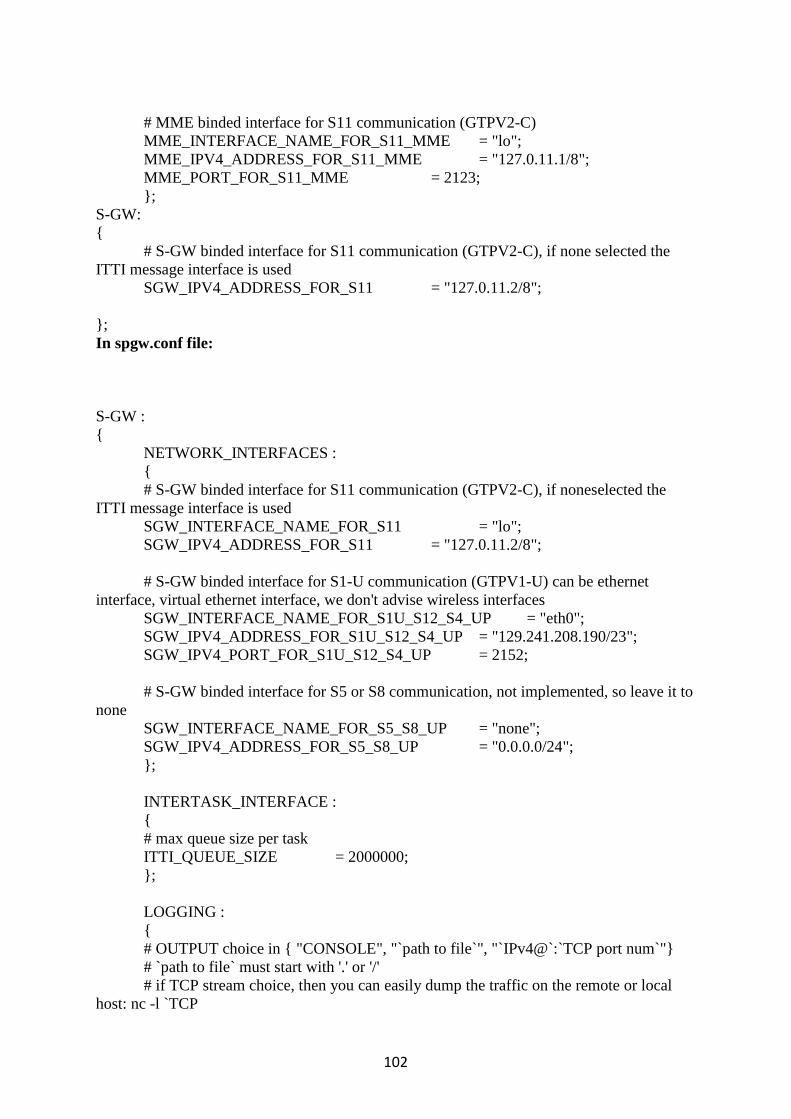
102
# MME binded interface for S11 communication (GTPV2-C)
MME_INTERFACE_NAME_FOR_S11_MME = "lo";
MME_IPV4_ADDRESS_FOR_S11_MME = "127.0.11.1/8";
MME_PORT_FOR_S11_MME = 2123;
};
S-GW:
{
# S-GW binded interface for S11 communication (GTPV2-C), if none selected the
ITTI message interface is used
SGW_IPV4_ADDRESS_FOR_S11 = "127.0.11.2/8";
};
In spgw.conf file:
S-GW :
{
NETWORK_INTERFACES :
{
# S-GW binded interface for S11 communication (GTPV2-C), if noneselected the
ITTI message interface is used
SGW_INTERFACE_NAME_FOR_S11 = "lo";
SGW_IPV4_ADDRESS_FOR_S11 = "127.0.11.2/8";
# S-GW binded interface for S1-U communication (GTPV1-U) can be ethernet
interface, virtual ethernet interface, we don't advise wireless interfaces
SGW_INTERFACE_NAME_FOR_S1U_S12_S4_UP = "eth0";
SGW_IPV4_ADDRESS_FOR_S1U_S12_S4_UP = "129.241.208.190/23";
SGW_IPV4_PORT_FOR_S1U_S12_S4_UP = 2152;
# S-GW binded interface for S5 or S8 communication, not implemented, so leave it to
none
SGW_INTERFACE_NAME_FOR_S5_S8_UP = "none";
SGW_IPV4_ADDRESS_FOR_S5_S8_UP = "0.0.0.0/24";
};
INTERTASK_INTERFACE :
{
# max queue size per task
ITTI_QUEUE_SIZE = 2000000;
};
LOGGING :
{
# OUTPUT choice in { "CONSOLE", "`path to file`", "`IPv4@`:`TCP port num`"}
# `path to file` must start with '.' or '/'
# if TCP stream choice, then you can easily dump the traffic on the remote or local
host: nc -l `TCP

103
OUTPUT = "CONSOLE";
# THREAD_SAFE choice in { "yes", "no" } means use of thread safe intermediate
buffer then a single thread pick each message log one
# by one to flush it to the chosen output
THREAD_SAFE = "yes";
# COLOR choice in { "yes", "no" } means use of ANSI styling codes or no
COLOR = "yes"; # TODO
# Log level choice in { "EMERGENCY", "ALERT", "CRITICAL", "ERROR",
"WARNING", "NOTICE", "INFO", "DEBUG", "TRACE"}
UDP_LOG_LEVEL = "TRACE";
GTPV1U_LOG_LEVEL = "TRACE";
GTPV2C_LOG_LEVEL = "TRACE";
SPGW_APP_LOG_LEVEL = "TRACE";
S11_LOG_LEVEL = "TRACE";
};
};
P-GW =
{
NETWORK_INTERFACES :
{
# P-GW binded interface for S5 or S8 communication, not implemented, so leave it to
none
PGW_INTERFACE_NAME_FOR_S5_S8 = "none";
PGW_IPV4_ADDRESS_FOR_S5_S8 = "0.0.0.0/24";
# P-GW binded interface for SGI (egress/ingress internet traffic)
PGW_INTERFACE_NAME_FOR_SGI = "eth0";
PGW_IPV4_ADDRESS_FOR_SGI = "129.241.208.190/23";
PGW_MASQUERADE_SGI = "yes";
};
# Pool of UE assigned IP addresses
IP_ADDRESS_POOL :
{
IPV4_LIST = (
"192.188.0.0/24",
"192.188.1.0/24"
);
};
# DNS address communicated to UEs
DEFAULT_DNS_IPV4_ADDRESS = "129.241.208.40";
DEFAULT_DNS_SEC_IPV4_ADDRESS = "129.241.206.252";
# Non standard feature, normally should be set to "no", but you may need to set to yes
for UE that do not explicitly request a PDN address through NAS signalling

104
FORCE_PUSH_PROTOCOL_CONFIGURATION_OPTIONS = "yes";
UE_MTU = 1428;
};
In HSS free diameter configuration file (hss_fd.conf):
Identity = “hss.openair4G.eur”;
Relam = “openair4G.eur”;
In MME free diameter configuration file (mme_fd):
Identity = “shyamalpc.openair4G.eur”;
Relam = “openair4G.eur”;
ConnectPeer= "hss.openair4G.eur" { ConnectTo = "127.0.0.1"; No_SCTP ; No_IPv6;
Prefer_TCP; No_TLS; port = 3868; realm = "openair4G.eur";};
In HSS configuration file (hss.conf):
HSS:
{
## MySQL mandatory options
MYSQL_server = "127.0.0.1";
MYSQL_user = "root";
MYSQL_pass = "mspwroot";
MYSQL_db = "oai_db";
## HSS options
OPERATOR_key = "11111111111111111111111111111111"; # OP key for oai_db.sql
RANDOM = "true";
## Freediameter options
FD_conf = "/usr/local/etc/oai/freeDiameter/hss_fd.conf";
};
Appendix 6 Running eNB, EPC and HSS
Install certificates:
cd ~/openair-cn/SCRIPTS
./check_hss_s6a_certificate /usr/local/etc/oai/freeDiameter/ hss.openair4G.eur
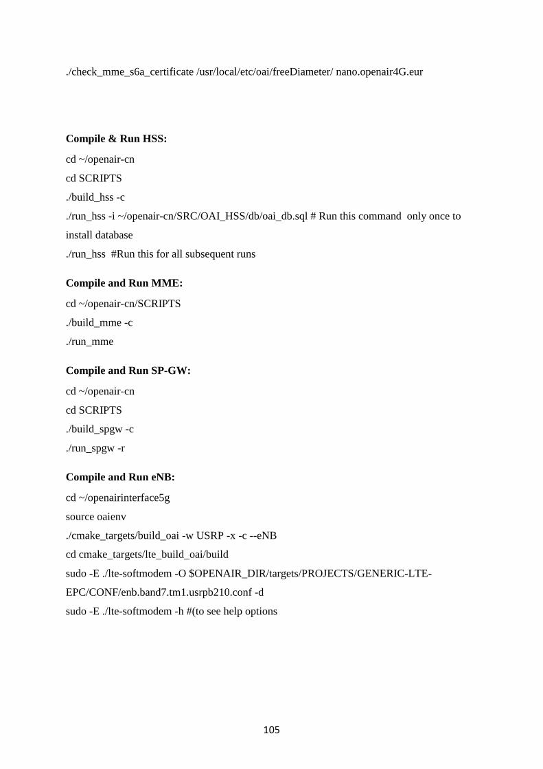
105
./check_mme_s6a_certificate /usr/local/etc/oai/freeDiameter/ nano.openair4G.eur
Compile & Run HSS:
cd ~/openair-cn
cd SCRIPTS
./build_hss -c
./run_hss -i ~/openair-cn/SRC/OAI_HSS/db/oai_db.sql # Run this command only once to
install database
./run_hss #Run this for all subsequent runs
Compile and Run MME:
cd ~/openair-cn/SCRIPTS
./build_mme -c
./run_mme
Compile and Run SP-GW:
cd ~/openair-cn
cd SCRIPTS
./build_spgw -c
./run_spgw -r
Compile and Run eNB:
cd ~/openairinterface5g
source oaienv
./cmake_targets/build_oai -w USRP -x -c --eNB
cd cmake_targets/lte_build_oai/build
sudo -E ./lte-softmodem -O $OPENAIR_DIR/targets/PROJECTS/GENERIC-LTE-
EPC/CONF/enb.band7.tm1.usrpb210.conf -d
sudo -E ./lte-softmodem -h #(to see help options

106
Appendix 7 User Registration on HSS Database
Adding user to table oai_db.users:
From the command line we can use mysql –u root –p command. The password is ´linux´.
mysql > use oai_db;
mysql > show tables;
mysql > select * from mmeidentity;
mysql > INSERT INTO users ( ´imsi´, ´msisdn´, ´imei´, ´imei_sv´, ´ms_ps_status´,
´rau_tau_timer´, ´ue_ambr_ul´, ´ue_amr_dl´, ´access_restriction´, ´mme_cap´,
´mmeidentity_idmmeidentity´, ´key´, ´RFSP-Index´, ´urrp_mme´, ´sqn´, ´rand´, ´OPc´)
VALUES (´208930000000001´, ´33638060010`, NULL, NULL, ´PURGED´ ´120´,
´50000000´, ´100000000´, ´47´, ´0000000000´, ´3´,
0x8BAF473F28FD09487CCCBD7097C6862, ´1´, ´0´, ´ ´,
0x00000000000000000000000000000000, ´ ´ );
Updating oai_db.mmeidentity and oai_db.pdn tables:
mysql > INSERT INTO pdn ( ´id´, ápn´, ´pdn_type´, ´pdn_ipv4´, ´pdn_ipv6´,
´aggregate_ambr_ul´, ´aggregate_ambr_dl´, ´pgw_id´, ´users_imsi´, ´qci´, `priority_level`,
´pre_emp_cap`, `pre_emp_vul`, ´LIPA-Permissions´) VALUES (´60´, ´oai.ipv4´, ´0.0.0.0´,
`0:0:0:0:0:0:0:0´, ´50000000´, ´100000000´, ´3´, ´208930000000001´, ´9´, ´15´,
´DISABLED´, ENABLED´, ´LIPA-ONLY´);
mysql > INSERT INTO mmeidentity (´idmmeidentity´, ´mmehost´, ´mmerelam´, ´UE-
reachability´) VALUES (´6´, ´shyamalpc.openair4G.eur´, ´openair4G.eur´, ´0´);

107
Appendix 8 OAI Results
Appendix 8-1 eNB Real Time issues

108
Appendix 8-2 OAI associated with MME before Crashed

109
Appendix 8-3 MME Screen

110
Appendix 8-4 MME, HSS, and SPGW connected successfully