Investigating Slug Flow Characteristics of a Pipline-Riser ... · PDF filethis work focuses on...
10
International Journal of Scientific & Engineering Research, Volume 8, Issue 2, February-2017 496 ISSN 2229-5518 IJSER © 2017 http://www.ijser.org Investigating Slug Flow Characteristics of a Pipline-Riser System Using Olga Simulation Tool Iwuchukwu A.R. 1 , Odutola T.O. 2 , Ossia C.V. 1 , Okoli J.U. 1 , Appah D. 2 (1=Offshore Technology Institute,University of Port Harcourt; 2= Gas Engineering Department, University of Port Harcourt) Abstract Slug flow is a predominant flow regime in offshore oil and gas production. This work investigated the slugging phenomenon in a pipeline-riser system. The pipeline has a nominal diameter of 0.3714m and spans a horizontal distance of 7.7km laid on an uneven seabed with a 200m riser. The OLGA 2015 simulation tool was used to develop the model, as well as carry out transient simulation. The liquid holdup, pressure, fluid temperature and water volume fraction were discussed. Hydrodynamic and severe slugging was found to occur along the pipeline and at the riser-base respectively. The pressure and temperature plots showed cyclic pattern; consequently, the system would be susceptible to fatigue, thermal stresses and thermal stress corrosion cracking. Information obtained from the liquid holdup and water volume fraction plots reveal that there was a very high potential for water overflow at the separator. This was noted to impact negatively on efficient offshore oil and gas production, and on integrity of offshore assets. Keywords: Slug flow, offshore, oil and gas production, fatigue —————————— —————————— 1. INTRODUCTION I t is an indisputable fact that Oil and Gas Industry remains the main stake of the global energy production. Oil and gas account for over 33% and 10% of global energy consumption respectively. Despite wide clamour, huge interest and rapid development of non-fossil fuel and renewable energy, it is predicted that they will remain the dominant energy source in several years to come. Oil and Gas exploitation and production involves the lifting and transportation of hydrocarbons from the reservoir, via the wellbore and piping systems, to the topside or other end facili- ties. A typical well-pipeline riser system of a typical offshore oil and gas production system is shown in Fig. 1. This system consists of three inter-connected subsystems; namely; the pro- duction well system, the subsea pipeline system and the verti- cal riser system. The separation process of gas/oil water is done on the topside. A choke valve is placed before the separa- tor at the topside to regulate the flow from the well. Fig. 1: A typical well-pipeline-riser system [5] As subsea processing remains comparatively unexploited; multiphase fluids of most offshore production systems are not separated on the seabed, but on the topside platform. Trans- portation of multiphase flow poses a lot of flow assurance challenges, such as: wax deposition [1], hydrate formation [2], solid particle erosion [3], asphatenes [4], slug formation [5], etc. Slug flow is one of the most predominant flow regimes in mul- tiphase flow; other flow regimes include stratified flow, wavy flow, annular flow, dispersed bubble flow and bubble flow. Slugging is an irregular multiphase flow characterized by a series of liquid plugs separated by a relatively large gas pock- ets; these liquids plugs whose length may vary from several meters to, sometimes, three or four times the riser length in severe cases [6]. Slug flow can be observed in many two-phase flow engineering applications; such as: flow in oil and gas pipelines [5] and other process industries [7]. The formation of the slug regime is transient in nature, passing from stratified to wavy flow, and then onto slug flow [8]. Slugging in oil and gas production poses a serious flow assur- ance concern for engineers and designers. The two main areas on which slug flow can cause difficulties to field operators are in the operability of the gas and liquid processing plant and in ______________________________________________________________________________________________ • Iwuchukwu A.R. is currently pursuing a MSc. Degree programme at the Offshore Technology Institute, School of Graduate Studies, University of Port Harcourt, Nigeria. • Odutola T.O. just concluded Doctorate of Phylosophy (Ph.D) work in Hydrate formation and mitigation at the Department of Petroleum En- gineering, University of Port Harcourt, Nigeria. E-mail: [email protected] IJSER
Transcript of Investigating Slug Flow Characteristics of a Pipline-Riser ... · PDF filethis work focuses on...

International Journal of Scientific & Engineering Research, Volume 8, Issue 2, February-2017 496 ISSN 2229-5518
IJSER © 2017 http://www.ijser.org
Investigating Slug Flow Characteristics of a Pipline-Riser System Using Olga Simulation Tool
Iwuchukwu A.R.1, Odutola T.O.2, Ossia C.V.1, Okoli J.U.1, Appah D.2 (1=Offshore Technology Institute,University of Port Harcourt; 2= Gas Engineering Department, University of Port Harcourt)
Abstract Slug flow is a predominant flow regime in offshore oil and gas production. This work investigated the slugging phenomenon in a pipeline-riser system. The pipeline has a nominal diameter of 0.3714m and spans a horizontal distance of 7.7km laid on an uneven seabed with a 200m riser. The OLGA 2015 simulation tool was used to develop the model, as well as carry out transient simulation. The liquid holdup, pressure, fluid temperature and water volume fraction were discussed. Hydrodynamic and severe slugging was found to occur along the pipeline and at the riser-base respectively. The pressure and temperature plots showed cyclic pattern; consequently, the system would be susceptible to fatigue, thermal stresses and thermal stress corrosion cracking. Information obtained from the liquid holdup and water volume fraction plots reveal that there was a very high potential for water overflow at the separator. This was noted to impact negatively on efficient offshore oil and gas production, and on integrity of offshore assets.
Keywords: Slug flow, offshore, oil and gas production, fatigue
—————————— ——————————
1. INTRODUCTION
It is an indisputable fact that Oil and Gas Industry remains
the main stake of the global energy production. Oil and gas account for over 33% and 10% of global energy consumption respectively. Despite wide clamour, huge interest and rapid development of non-fossil fuel and renewable energy, it is predicted that they will remain the dominant energy source in several years to come.
Oil and Gas exploitation and production involves the lifting and transportation of hydrocarbons from the reservoir, via the wellbore and piping systems, to the topside or other end facili-ties. A typical well-pipeline riser system of a typical offshore oil and gas production system is shown in Fig. 1. This system consists of three inter-connected subsystems; namely; the pro-duction well system, the subsea pipeline system and the verti-cal riser system. The separation process of gas/oil water is done on the topside. A choke valve is placed before the separa-tor at the topside to regulate the flow from the well.
Fig. 1: A typical well-pipeline-riser system [5] As subsea processing remains comparatively unexploited; multiphase fluids of most offshore production systems are not separated on the seabed, but on the topside platform. Trans-portation of multiphase flow poses a lot of flow assurance challenges, such as: wax deposition [1], hydrate formation [2], solid particle erosion [3], asphatenes [4], slug formation [5], etc.
Slug flow is one of the most predominant flow regimes in mul-tiphase flow; other flow regimes include stratified flow, wavy flow, annular flow, dispersed bubble flow and bubble flow. Slugging is an irregular multiphase flow characterized by a series of liquid plugs separated by a relatively large gas pock-ets; these liquids plugs whose length may vary from several meters to, sometimes, three or four times the riser length in severe cases [6]. Slug flow can be observed in many two-phase flow engineering applications; such as: flow in oil and gas pipelines [5] and other process industries [7]. The formation of the slug regime is transient in nature, passing from stratified to wavy flow, and then onto slug flow [8].
Slugging in oil and gas production poses a serious flow assur-ance concern for engineers and designers. The two main areas on which slug flow can cause difficulties to field operators are in the operability of the gas and liquid processing plant and in
______________________________________________________________________________________________
• Iwuchukwu A.R. is currently pursuing a MSc. Degree programme at the Offshore Technology Institute, School of Graduate Studies, University of Port Harcourt, Nigeria.
• Odutola T.O. just concluded Doctorate of Phylosophy (Ph.D) work in Hydrate formation and mitigation at the Department of Petroleum En-gineering, University of Port Harcourt, Nigeria. E-mail: [email protected]
IJSER
International Journal of Scientific & Engineering Research, Volume 8, Issue 2, February-2017 497 ISSN 2229-5518
IJSER © 2017 http://www.ijser.org
the mechanical integrity of the pipework upstream of the plant [9]. In most cases, the separator overflows, and liquid ends up in gas outlet, causing severe damage of processing facilities. Similarly, slugging can also cause disturbance to gas handling facilities, with compressors being forced in and out of cycle; while at bends, there will be changes in reaction forces as slug enters and leaves the bend. Pipeline slugging is very turbu-lent; the turbulence will tend to scrape off any corrosion pro-tection in the pipeline, as well as, the protective scale; ensuring that the pipe is always exposed to the corrosive environment [10]. Hence, the integrity and reliability of the piping systems and end facilities are severely affected by slugging.
In some cases, a very high upstream pressure is required to push the slug through the system. Such high upstream pres-sure can reduce the flow rate of the well. In terrain-induced slugging, the liquid slug completely blocks the flow in the sys-tem. During this period, there is no production at all, until the pressure builds up to push out the liquid slug [5]. This results to a major instability in the system.
The problem of slugging is not new in the industry; several efforts have been made to mitigate/eliminate its occurrence. However, slug prediction and simulation still poses a serious challenge to the industry. More studies are ongoing for better understanding of the phase transition associated with slug-ging; as well as, more robust models are being developed for liquid holdup in liquid slug and elongated bubble. However, this work focuses on the application of OLGA Simulation tool to model, simulate and predict slug occurrence in a generic pipeline-riser system.
1.1 SLUG MODELING AND PREDICTION
Slug flow and its associated problems have long being ex-plored since 1970s. Several researches and experiments have being carried out to investigate its occurrence, prediction and elimination strategies in oil and gas production.
The Unit Cell concept was first extensively explored by Duck-ler and Hubbard [11]. They establish fundamental equations describing slug velocity from considering a mass balance over the film region and the slug. This concept, which is the most accepted approach, tends to reduce the intermittency to perio-dicity and assume fully-developed flow so that the complex structure can be simplified to an equivalent unit cell, consist-ing of a liquid slug and a long bubble [12]. Several advance studies based on this concept have been developed ([13], [14],). Particularly, Nicholson et al. noted equations for the prediction of slug translational velocity were insufficient; hence, a new concept, drift velocity, was defined to model their results [14]. Obvious drawbacks and limitations of this model include: loss of symmetry in vertical flow; influence of flow regimes, annu-lar to stratified regime of the film; limitations on gas fraction and bubble motion prediction modelling. Schmidt et al. pre-
sented a simple hydrodynamic computer model [15]. This model simulates a complete severe-slugging cycle in a flow-line/riser system where the flowline is modelled by a gas buffer, with only a short flowline to the riser. However, the model fails to account for the influence of two-phase flow in the upstream pipeline; hence, limiting its applicability. Small scale tests were conducted for the prediction of severe slug-ging in offshore lines, and evaluation of the possibility of its reduction/elimination [6]. The results obtained revealed that liquid viscosity had no effect on the occurrence of severe slug-ging, but an increase in viscosity reduces the slug-arrival ve-locity; Riser-base supplementary gas lift reduces severe-slugging severity; however, unrealistically large amounts of extra gas are required for the complete removal of severe-slugging features. However, this work was carried out with limited range of liquid viscosities; if a broad range is experi-mented, results may reveal effects of liquid viscosities on se-vere slug occurrence. While working on British Petroleum (BP) Exploration, Hill and Wood developed a modified model for predicting slug frequency, slug length and maximum possible slug length prediction [9]. Based on extensive data obtained from Wytch Farm and Prudhoe Bay field, they developed a modified equation for the Slug frequency. The results showed better correlation when compared to the existing model. An-other significant contribution to slug flow modelling was made by Taitel and Barnea [16]. Assuming a uniform film thickness and a simplified momentum balance equation, they carried out the calculation of pressure gradients in steady state slug flow in inclined pipes using liquid hold up. A steady-state two-fluid model was developed by De Henau and Raithby [17]. Strong correlations for air-water and air-oil slug flow in horizontal pipes were obtained over a limited range of ex-perimental data. Meanwhile, Orell [18] advanced the works of Taitel and Barnea [16] to calculate pressure drop, taking into consideration the application of Reynolds number in friction factor calculation.
Further studies were carried out in Bagci and Al-shareef [19] to illustrate the slug flow in horizontal and inclined pipes. They developed a mathematical model and a computer pro-gram which was based on the sink/source concept at the pipe-line connections. The effects of changes in film characteristics, superficial liquid velocity, inclination angle, pipeline diame-ters, and superficial gas velocity on slug flow characteristics were also investigated. Throneberry et.al [20] investigated the solid particle erosion phenomenon on slug flow. Conducting experiment using “Boom loop” and electrical resistance (ER) probes, they developed a mechanistic model for predicting erosion rates, which was consistent over the range of experi-mental testing. Ansari and Shokri [21] developed a numerical model of slug flow initiation in horizontal channels using a two-fluid model. Applying the governing equations of the two-fluid model, hyperbolic analysis of the two-fluid “Pres-
IJSER

International Journal of Scientific & Engineering Research, Volume 8, Issue 2, February-2017 498 ISSN 2229-5518
IJSER © 2017 http://www.ijser.org
sure Free Model,” and closure models, a numerical solution method that solved transient two-fluid equations using a class of high-resolution shock capturing methods was developed based on TVD Lax- Freidrichs (High order) method. A simpli-fied dynamical model for severe slugging in pipeline-riser systems was developed by Jahanshahi and Skogestad [22]. They compared their results, together with other previous models such as: ‘Storkaus model’ [23], ‘Di-Meglio model’ [24], ‘Kaasa model’ [25], and ‘Nydal model’ [26] with the results from the OLGA Simulator. The result obtained showed the proposed model was able to maintain the main dynamics of the severe slugging flow regime. A methodology for calcula-tion of a slug, two-phase flow hold-up in a horizontal pipe has been presented [8]. The proposed model was both tested ex-tensively against experimentally collected data and verified with data for slug flow in horizontal pipes obtained from oth-er sources. The developed model gave excellent results with less than 7% error, and was proven to be more accurate when compared to existing models. Kjølaas et al. [18] simulated the hydrodynamic slug flow using the LedaFlow slug capturing model. The LedaFlow 1D model employed a three-fluid nine-field modelling approach to simulate the thermodynamics and hydrodynamics of the gas-oil-water flow in pipeline systems. The two-phase experiments which were conducted in 2003 at the Large Scale Loop at SINTEF Laboratory were analysed and compared with the LedaFlow model. The results obtained showed a good agreement between the Ledaflow Slug Captur-ing model and the experimental data (for GLR=10). Losi et al. [28] conducted a study on modelling and statistical analysis of high viscosity oil/air slug flow characteristics in a small diame-ter horizontal pipe. The study adopted a statistical approach which generated probability density functions for slug lengths. A new correlation was used to model their depend-ency on superficial gas velocity. The pressure drop obtained from the model showed good agreement with experimental data, providing information about the mechanics of the flow regime.
1.2 OLGA TRANSIENT SIMULATION TOOL
OLGA software is a dynamic multiphase simulator widely used in the Oil and Gas industry for transient simulation [29]. Coined as a short form for "OiL and GAs simulator, the model-ing tool makes it possible to simulate fluid flow, ensuring im-proved efficiency and optimization of offshore oil and gas production. OLGA is used for modeling and simulation of networks of wells, pipelines, risers and process equipment, covering the production system from bottom hole to the processing facilities.
OLGA is applied for engineering throughout field life from conceptual studies to support of operations. It is predominant-ly used both in the engineering and design phase, as well as in operation phase of any offshore project. During design and
engineering stage, OLGA is very useful for mapping of opera-tional limits and to establish standard operational procedures, with emphasis on optimizing the production window during field life. OLGA is also used for safety analysis and risk as-sessment of equipment malfunctions and operational failures. During operation, OLGA is used to establish operational pro-cedures and limitations, emergency response and contingency plans. OLGA is also a very useful tool for training operators on current best practices in the industry.
During operation phase, several events where OLGA simula-tion is extensively used can be summarized below;
• Pipeline start-up and shut-down • Pipeline blow-down • Change in production rates (Turn-up slugging analy-
sis) • Design of Process equipment (Compressor, Pump,
Separator, Choke etc.) • Pipeline pigging (Pigging Slug Analysis) • Hydrate control • Wax deposition • Tuning (Sensitivity and post-optimal analysis) • Wells: Flow stability, Artificial lift, WAG injection,
Well Testing, Well control • Safety and Risk Analysis • Training of operators. • Front End Engineering and Design
OLGA 2015.1 is the latest version in a continuous development which was started by the Institute for Energy Research (IFE) in 1980. The oil industry started using OLGA in 1984 when Sta-toil had supported its development for three years. Data from the large scale flow loop at SINTEF, and later from the me-dium scale loop at IFE, were essential for the development of the multiphase flow correlations and also for the validation of OLGA. Since then, oil and gas companies have supported its development, and provided relevant field data to help manage uncertainty, predominantly within the OLGA Verification and Improvement Project (OVIP).
2. METHODOLOGY
The OLGA 2015.1 simulation tool was used in this work. The uniqueness of this version when compared with the other ver-sion is the introduction of a new slugtracking model “OL-GA2015”. OLGA2015 implements a stochastic slug initiation methodology which simulated the irregular behavior of slug-ging over time; thus, characterizing the slug initiation better. Previous versions used “OLGA6” slugtracking model. The HydrSlug-pvt module was adopted; this was due to limitation of available information and computation constraints. The module models hydrodynamic slugging using PVT Lookup table. The lookup table file is based on a PVT analysis and computation of thermodynamic properties of a fluid with con-
IJSER

International Journal of Scientific & Engineering Research, Volume 8, Issue 2, February-2017 499 ISSN 2229-5518
IJSER © 2017 http://www.ijser.org
stant total composition. A table file is normally generated by using a fluid property package with a specialized OLGA table file generator. A PVT Lookup table file contains tables for va-rying pressure and temperature for basic fluid properties for gas and liquid, and optionally water as a separate phase. When applying the PVT Lookup tables, OLGA reads the table files and interpolates in the property tables to obtain fluid and related phase properties for specific pressures and tempera-tures at every segment along a pipeline. The system configura-tion is shown in Fig. 2. This consists of an inlet (closed node), an outlet (pressure node), a branch (pipeline-riser system) and a valve (hydrodynamic choke valve).
Fig. 2: The system configuration
The pipeline under study has an approximate horizontal length of 7700m and a riser length of 200m. The seabed ba-thymetry is uneven, enabling formation of hydrodynamic slugging; and steep undulating at riser-base, enabling terrain-induced slugging. The OLGA simulation tools models the
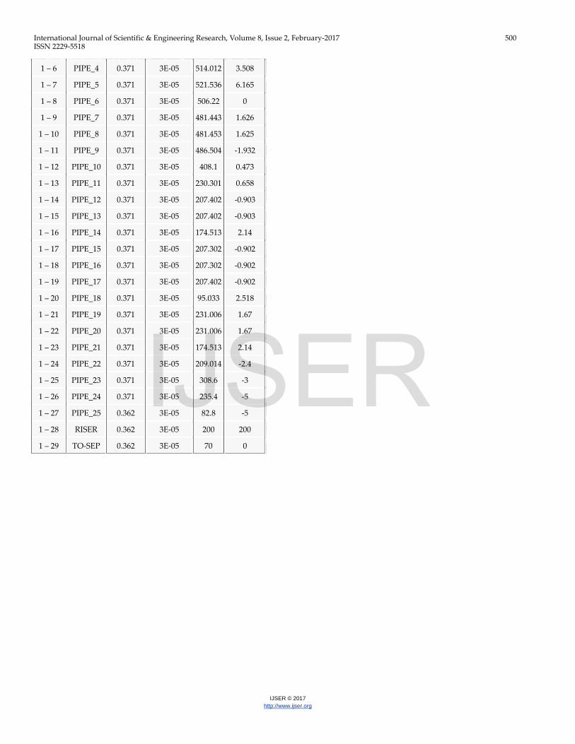
pipeline (BRANCH-1) as a number of pipes stretching be-tween two points in space, divide into a number of segments (Control volume). The pipeline profile is shown in Fig. 3; while the detailed geometry and properties are given in Table 1. A summary of the options used in the modeling are stated in Table 2.
The simulation was carried out for two hours; wax deposition and heat loss from the pipe is negligible. The pipe is solid and rigid, with negligible elastic deformation. The fluid flowing in the pipeline is multiphase, with three phases – oil, water and gas; sand and other solid particles are assumed to be negligi-ble. The flow model used is OLGA HD stratified flow model, which gives a 3-dimensional flow description at 1-dimensional speed. As earlier stated, the PVT fluid file was used as input data for fluid properties; hence compositional tracking was not carried out. This reduces the computational space and time required in the modeling. “1STORDER” mass equation scheme was used; this is more rigorous, and gives more accu-rate solution when compared to the alternative “2NDORDER” mass equation scheme. The fluid inlet temperature is 72.3oC while the pressure regulated by the valve at the outlet is 683 bar atm.
Fig. 3: The pipeline-riser system profile
Table 1: Branch-1 Pipeline system geometry and configuration
Pipe no. Label Diameter
(m) Roughness
(m) Length
(m) Elevation
(m)
1 – 1 INLET 0.362 3E-05 100 0
1 – 2 INLET_B 0.362 3E-05 173 0
1 – 3 PIPE_1 0.371 3E-05 151 0
1 – 4 PIPE_2 0.371 3E-05 355.217 -0.001
1 – 5 PIPE_3 0.371 3E-05 514.012 3.507
IJSER
International Journal of Scientific & Engineering Research, Volume 8, Issue 2, February-2017 500 ISSN 2229-5518
IJSER © 2017 http://www.ijser.org
1 – 6 PIPE_4 0.371 3E-05 514.012 3.508
1 – 7 PIPE_5 0.371 3E-05 521.536 6.165
1 – 8 PIPE_6 0.371 3E-05 506.22 0
1 – 9 PIPE_7 0.371 3E-05 481.443 1.626
1 – 10 PIPE_8 0.371 3E-05 481.453 1.625
1 – 11 PIPE_9 0.371 3E-05 486.504 -1.932
1 – 12 PIPE_10 0.371 3E-05 408.1 0.473
1 – 13 PIPE_11 0.371 3E-05 230.301 0.658
1 – 14 PIPE_12 0.371 3E-05 207.402 -0.903
1 – 15 PIPE_13 0.371 3E-05 207.402 -0.903
1 – 16 PIPE_14 0.371 3E-05 174.513 2.14
1 – 17 PIPE_15 0.371 3E-05 207.302 -0.902
1 – 18 PIPE_16 0.371 3E-05 207.302 -0.902
1 – 19 PIPE_17 0.371 3E-05 207.402 -0.902
1 – 20 PIPE_18 0.371 3E-05 95.033 2.518
1 – 21 PIPE_19 0.371 3E-05 231.006 1.67
1 – 22 PIPE_20 0.371 3E-05 231.006 1.67
1 – 23 PIPE_21 0.371 3E-05 174.513 2.14
1 – 24 PIPE_22 0.371 3E-05 209.014 -2.4
1 – 25 PIPE_23 0.371 3E-05 308.6 -3
1 – 26 PIPE_24 0.371 3E-05 235.4 -5
1 – 27 PIPE_25 0.362 3E-05 82.8 -5
1 – 28 RISER 0.362 3E-05 200 200
1 – 29 TO-SEP 0.362 3E-05 70 0
IJSER

International Journal of Scientific & Engineering Research, Volume 8, Issue 2, February-2017 501 ISSN 2229-5518
IJSER © 2017 http://www.ijser.org
Fig. 4: A plot of Liquid Holdup variation with simulated time
Table 2: Modeling Options applied in the simulation
Overall setting
Flow model OLGAHD
Mass eq scheme 1STORDER
Compositional model OFF
Debug OFF
Drilling OFF
Phase THREE
Elastic walls OFF
Void in slug SINTEF
Steady state ON
User defined plug-in OFF
Temp. calc. ADIABATIC
Wax deposition OFF
Restart OFF
Integration
Simulation starttime 0 s
Simulation stoptime 2 h
Minimum time step 0.01 s
Maximum time step 1
It is important to note that there are four major sections of in-terest in the model; they include: Inlet, Riser-base, Riser-top and Outlet.
3. RESULTS AND DISCUSSIONS
As earlier stated, the model simulation time is two (02) hours. However, for clarity, the various plots presented in this section show results for 64 min. These results are given below:
3.1 Liquid holdup
Fig. 4 shows the plot of the liquid holdup with time. The liq-uid holdup at the inlet (depicted with a blue curve) has a fairly constant value of 0.4. This shows that the well composition is 40% liquid and 60% gas. As expected, the liquid holdup base builds up at the riser for an average period of 200s attaining a peak value of 1 when the riser-base is completely blocked by the liquid; meanwhile, there is steady decline in liquid vo-lume is at the outlet. The produced gas builds up behind the liquid slug for period of 360s; until it is sufficient to push the liquid slug up through the riser. During this period, produc-tion is cut off because of the accumulation of slugs at riser-base. As the gas pressure sufficiently pushes the liquid accu-mulated at the riser-base, the liquid holdup at the riser-top increases, attaining its peak value of 0.66 at 440s.
The second slug profile at the riser-base builds-up at about 800s of the simulation period. The liquid fraction at the top of the riser increases, attaining a peak value of 1. The liquid hol-dup at the outlet is fairly regulated by the choke valve, with high spikes within intervals. Such spikes cause serious prob-lems in the separator. The separator would experience liquid
IJSER

International Journal of Scientific & Engineering Research, Volume 8, Issue 2, February-2017 502 ISSN 2229-5518
IJSER © 2017 http://www.ijser.org
overflow which would impact negatively on other processing and gas handling equipments. It is important note that cyclic nature of this occurrence can create fatigue stress on the pipe-line, riser and the separator.
3.2 Pressure and Temperature
The plot of the pressure variation with time is shown in Fig. 5. The outlet pressure is regulated at 68.3 bar atm. by the choke valve located between the riser-top and the outlet. The pres-sure at the inlet and the riser-base builds up as severe slugs accumulate at the riser base, attaining maximum values of 87.5 bar and 84 bar, respectively. The sharp decrease in pressure occurs when the gas pushes the liquid slugs up through the
riser; the cycle is repeated over again after every 817s. The pressure at the inlet is higher than the pressure at the riser-base throughout the simulation period, with a maximum dif-ferential value of 18.5 bar occurring at about 1510s of simula-tion time. This is attributed to the pressure drop that occurs as the fluid flow through the 7.7km pipeline. The pressure at the riser-top also shows a recurring pattern, with a critical value of 72.5 bar. The recurring pattern of the pressure at the inlet, riser-base and outlet poses serious threat to integrity of the pipeline, especially at tees and elbow locations [6].
Fig. 5: A Plot of Pressure variation with simulated time
IJSER

International Journal of Scientific & Engineering Research, Volume 8, Issue 2, February-2017 503 ISSN 2229-5518
IJSER © 2017 http://www.ijser.org
Fig. 6: A plot of Fluid Temperature variation with simulated time
Fig. 7: A plot of Water volume fraction with time
From Fig. 6, the fluid temperature at the inlet is fairly constant at 72.3 oC, as specified during the modeling. The temperature at the riser-base, riser-top and outlet increases steadily during the slug accumulation phase, but decreases sharply as the liq-uid slug is pushed up by the accumulated gas. It is important to note that the process is assumed adiabatic; hence, there is no heat loss to the pipewall. In real-life, the temperatures
would be lower than those presented here. Thermal stresses created by irregular nature of the temperature pose serious design challenges, as potentials for creep and thermal-induced corrosion in the pipeline is very high.
The minimum temperature obtained is about 63OC; this is above the pour-point for wax formation, as well as asphatenes
IJSER

International Journal of Scientific & Engineering Research, Volume 8, Issue 2, February-2017 504 ISSN 2229-5518
IJSER © 2017 http://www.ijser.org
and hydrate formation temperature. It is important to note that adiabatic condition was assumed. This means that there is no temperature loss to the environment. This is not obtainable in practice, considerable drop in temperature as flowing fluids continuously lose heat to the cold seabed environment. Such temperature drop can lead to formation of hydrates, wax and asphatene deposits. These occurrences will have a multiplier effect on the severity of slugging.
3.3 Water Volume fraction
The water volume fraction for the simulated flow is shown in Fig. 7. Typical of several green field found in the Gulf of Gui-nea, the multiphase flow through the inlet has a volume frac-tion of 0.135. It is important to note that the water fraction in the riser-base (illustrated by the red curve) rises to a critical value of 0.93 within 18 min of production flow. This is as a result of severe slugging at the riser-base. Water, having the highest density, accumulates at the base of the riser. The ac-cumulation of gas behind the slug pushes the water-slug up the riser, as can be seen in the increasing water volume frac-tion at riser-top after 20 min and consequently, increasing wa-ter volume fraction at the outlet after 23 min. With a peak wa-ter volume fraction of 0.62 at the outlet, there is very high ten-dency of water overflow at the separator. Its grave conse-quences on production and flow assurance cannot be over-emphasized.
4. CONCLUSIONS
This work has successfully investigated the slug characteristics of a generic pipeline-riser using OLGA 2015 simulation tool. The conclusions made from this study include:
a) The liquid holdup curve reveals that severe slugging would occur at the riser-base, completely blocking the riser-base for a mean period of 460 s; this will cause major instabili-ties in the system
b) From the liquid holdup and water volume fraction plots, a maximum liquid volume fraction of 0.9 and water vo-lume fraction of 0.63 occurs at the outlet at about 1410 s. This indicates a high possibility of liquid overflow at the separator.
c) The cyclic behavior of the pressure and temperature makes the system vulnerable to fatigue stresses, thermal stresses, and thermal stress corrosion cracking on the pipeline, riser and processing facilities.
REFERENCES
[1] Bern, P.A., Withers, V.R. and Cairns, R.J. (1980). Wax deposition in Crude Oil Pipelines. Journal of Society of Petroleum Engi-neers; http://dx.doi.org/10.2118/206-1980-MS
[2] Behar, E. (1994). Hydrates Problems within the Framework of Multiphase Production and Transportation of Crude Oils and
Natural Gases: Part 1 – Physical Chemistry of Hydrates Forma-tion and Dissociation. Review IFP 49(3):265
[3] McLaury, B.S., Wang, J., Shirazi, S.A., Shadley, J.R. and Rybick, E.F. (1997). Solid Particle Erosion in Long Radius Elbows and Straight Pipes. SPE Annual Technical Conference and Exhibition, 5-8 October, San Antonio Texas. http://dx.doi.org/10.2118/38842-MS
[4] Moricca, G. and Trabucchi, G. (1996). Effective Removal of As-phaltene deposits from Pipelines and Treating Plants. SPE-36834-MS; European Petroleum Conference, 22-24 October, Milan Italy. http://dx.doi.org/10.2118/36834-MS
[5] Pedersen, S., Durdevic, P. and Yang, Z. (2016). Challenges in Slug Modelling and Control for Offshore Oil and Gas Production: A Review study. International Journal of Multiphase Flow., doi:10.1016/j.ijmultiphaseflow.2016.07.018
[6] Pots, B.F., Bromilow, I.G. and Konjin, M.J. (1987). Severe Slug Flow in Offshore Flowline/Riser Systems. SPE Production Engi-neering, pp. 319-324.
[7] Chhabra, R.P. and Richardson, J.F. (1999). Non-Newtonian Flow in the Process Industry: Fundamentals and Engineering Applica-tions. Butterworth-Heinemann Publishers. http://www.sciencedirect.com/science/book.9780750637701
[8] Hassanlouei, R.N., Firouzfar, H., Kasiri, N. and Khemof M.H. (2012). A Simple Mathematical Model for Slug Liquid Holdup in Horizontal Pipes. Scientia Iranica, Transaction C: Chemistry and Chemical Engineering, 19, pp. 1653-1660.
[9] Hill, T.J. and Wood, D.G. (1994). Slug Flow: Occurrence, Conse-quences, and Prediction. Society of Petroleum Engineers, SPE 27960, pp. 53-62.
[10] Sun, J-Y. and Jepson, W.P. (1992). Slug Flow Characteristics and their Effects on Corrosion Rates in Horizontal Oil and Gas Pipe-lines. SPE Annual Technical Conference and Exhibition, Wash-ington, DC, October 4-7.
[11] Duckler, A.E. and Hubbard, M.G. (1975). A Model for Gas-Liquid Slug Flow in Horizontal and Near Horizontal tubes. Ind. Eng. Chem. Fundam., 14, pp. 337-347.
[12] Wallis, G.B. (1969). One-dimensional two-phase flow, NY: McGraw-Hill Book Company
[13] Kokal, S.L. and Stanisluv, J.F. (1989). An Experimental Study of Two-Phase Flow in Slightly Inclines Pipes-II: Liquid Holdup and Pressure Drop. Chem. Eng. Sci., 44, pp. 681-693.
[14] Nicholson, M.K., Aziz, K. and Gregory, G.A. (1978). Intermittent Two Phase Flow in Horizontal Pipes: Predictive Models. Can. J. Chem. Eng,. 56, pp. 653-663.
[15] Schmidt, Z., Doty, D.R. and Dutta-Roy, K. (1985). Severe Slug-ging in Offshore Pipeline Riser-Pipe Systems. SPE J (Feb 1985) 27-38.
[16] Taitel, Y. and Barnea, D. (1990). A Consistent Approach for Cal-culating Pressure Drop in Inclined Slug Flow. Chem. Eng. Sci., 45, pp. 1199-1206.
IJSER

International Journal of Scientific & Engineering Research, Volume 8, Issue 2, February-2017 505 ISSN 2229-5518
IJSER © 2017 http://www.ijser.org
[17] De Henau, V. and Raithby, G.B. (1995). A Transient Two-Fluid Model for the Simulation of Slug Flow in Pipelines-I, Theory. Int’l Journal of Multiphase Flow, 21, pp. 335-349.
[18] Orell, A. (2003). Experimental Validation of a Simple Model for Gas-Liquid Slug Flow in Horizontal Pipes. Chem. Eng. Sci., 60, pp. 1371-1381.
[19] Bagci, S. and Al-Shareef, A. (2003). Characterization of Slug Flow in Horizontal and Inclined Pipes. Society of Petroleum Engi-neers, SPE 80930, pp 1-10.
[20] Throneberry J.M., Zhang, Y., McLaury, B.S., Shirazi, S.A. and Rybicki, E. F. (2010). Solid Particle Erosion in Slug Flow. Society of Petroleum Engineers, SPE 135402, pp. 1-16.
[21] Ansari, M.R. and Shokri, V. (2010). Numerical modeling of slug flow initiation in a horizontal channels using s two-fluid model. International Journal of Heat and Fluid Flow 32, 145-155.
[22] Jahanshahi, E. and Skogestad, S. (2011). Simplified Dynamical Models for Control of Severe Slugging in Multiphase Risers. Conference Proceeding of the 18th IFAC World Congress, Milano (Italy), August 28 – September 2, 2011.
[23] Storkaas, E. and Skogestad, S. (2003). A Low-Dimensional Dy-namic Model of Severe Slugging for Control Design and Analy-sis. 11th Int’l Conference on Multiphase Flow, San Remo, Italy, BHR Group.
[24] Di Meglio F., Kaasa G.O., Petit N., Alstad V. (2010): Reproducing slugging oscillations of a real oil well. IEEE. 49th IEEE Confe-rence on Decision and Control, Atlanta,United States. pp.4473-4479.
[25] Kaasa, G.-O., Alstad, V., et al. (2008). Attenuation of Slugging in Unstable Oil Wells by Nonlinear Control. 17th IFAC World Con-gress, Seoul, Korea.
[26] Da Silva, C.M, and Nydal O.J. (2010). Dynamic Multiphase Flow Model for Control. BHRG 7th North American Conference of Multiphase Technology, Banff, Canada.
[27] Kjølaas, J., De Leebeeck, A. and Johansen, S.T. (2013). Simulation of hydrodynamic slug flow using the LedaFlow slug capturing model. BHR Group Multiphase 16,265-383
[28] Losi, G., Arnone, D., Correra S., and Poesio, P. (2016). Modelling and Statistical analysis of high viscosity oil/air slug flow charac-teristics in a small diameter horizontal pipe. http://dx.doi.org/10.1016/j.ces.2016.04.005.
[29] Bendiksen, K.H., Malnes, D., Moe, R. et al. (1991). The Dynamic Two-Fluid Model OLGA: Theory and Application. SPE Prod. Eng. 6(2):171-180. SPE-19451-PA.
IJSER


![[PPT]Slug · Web viewSlug flow in S-shaped risers Simulating S-riser in OLGA Extending the simplified MATLAB model for L-riser to S-riser Comparing the results from OLGA and MATLAB](https://static.fdocuments.us/doc/165x107/5aad95117f8b9a9c2e8e7f2d/pptslug-viewslug-flow-in-s-shaped-risers-simulating-s-riser-in-olga-extending.jpg)