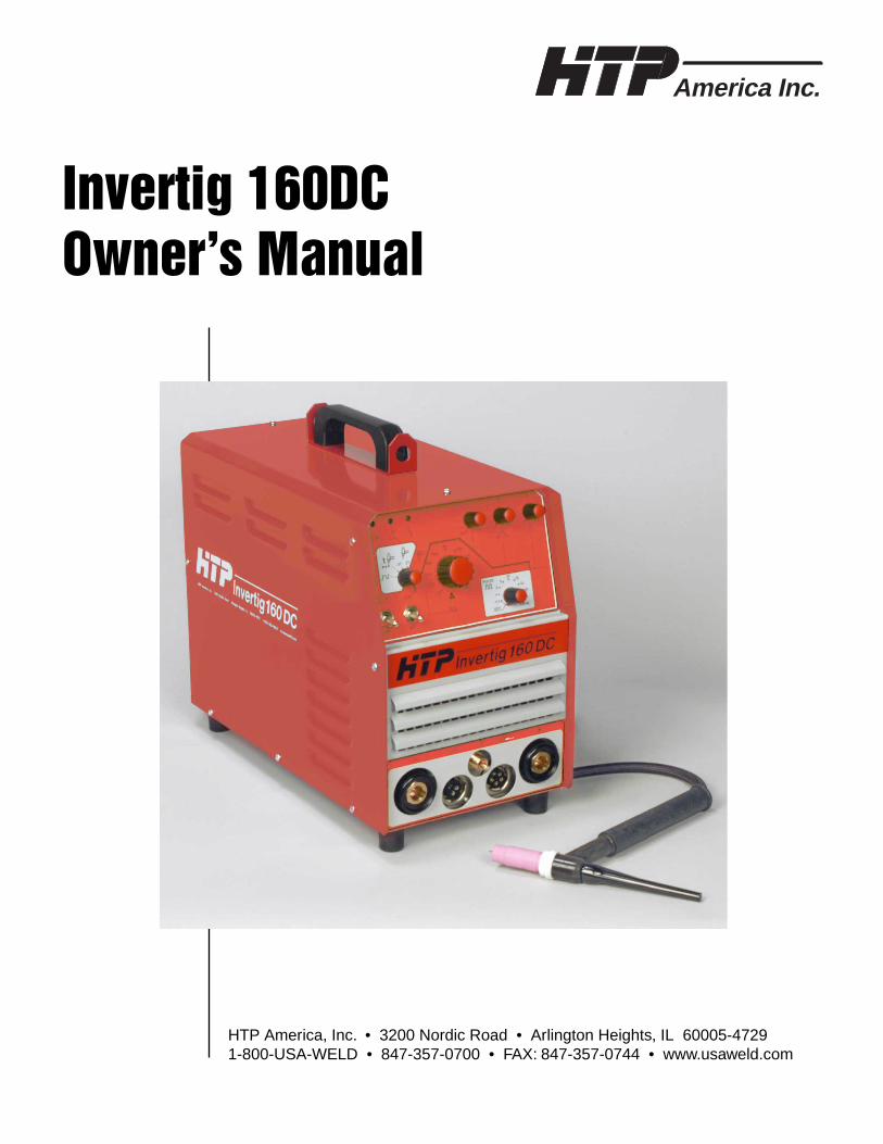
Invertig 160DC Owner’s Manual - USA Weld Man 03.03.05.pdf · America Inc. Invertig 160DC...
20
America Inc. Invertig 160DC Owner’s Manual HTP America, Inc. • 3200 Nordic Road • Arlington Heights, IL 60005-4729 1-800-USA-WELD • 847-357-0700 • FAX: 847-357-0744 • www.usaweld.com
-
Upload
nguyendang -
Category
Documents
-
view
213 -
download
0
Transcript of Invertig 160DC Owner’s Manual - USA Weld Man 03.03.05.pdf · America Inc. Invertig 160DC...
America Inc.
Invertig 160DCOwner’s Manual
HTP America, Inc. • 3200 Nordic Road • Arlington Heights, IL 60005-47291-800-USA-WELD • 847-357-0700 • FAX: 847-357-0744 • www.usaweld.com

2
Manufacturer’s Warranty
It is expressly agreed that there are no warranties, expressed or implied, made by either the Salesman,Dealer, or HTP America, Inc. on products or parts furnished hereunder, except the Manufacturer’sWarranty against defective materials or workmanship as follows:
HTP America, Inc. warrants each new welding machine to be free from defects in material andworkmanship under normal use and service for three years after delivery to the original purchaser. HTP America, Inc. will repair and replace, at its factory, any part or parts thereof, products to be returnedto HTP America, Inc. with transportation charges prepaid and which its examination shall disclose to itssatisfaction to have been thus defective. This warranty being expressly in lieu of all other warranties,expressed or implied, and all other obligations or liabilities on its part and it neither assumes norauthorizes any other person to assume for it any other liability in connection with the sale of its machines.
This warranty shall not apply to any welding machine which has been repaired or altered by unauthorizedservice departments in any way so as in the judgment of HTP America, Inc. to affect its stability and reliability, nor which has been subjected to misuse, negligence or accident.
HTP America, Inc. shall not be liable in any event, unless HTP America, Inc. receives notice of alleged breach of warranty within not more than 30 days after the discovery, actual or constructionalleged breach of warranty specifying the claimed defect.
HTP America, Inc. has reserved the right to make change in design or add any improvements to its products at any time without incurring any obligation to install same on equipment.
This warranty is void unless warranty card is sent to HTP America, Inc. within 15 days from date of purchase.
Note:Exclusions to Warranty:
1. The Tig Welding Torch is warranted for a period of ninety (90) Days against defects in material and workmanship.
2. The tungsten, collet, collet body, ceramic nozzles are consumable items, WHICH CARRY NO WARRANTY.
Index
Warranty . . . . . . . . . . . . . . . . . . . . . . . . . . . . . . . . . . . . 2Index . . . . . . . . . . . . . . . . . . . . . . . . . . . . . . . . . . . . . . . 2Safety Suggestions . . . . . . . . . . . . . . . . . . . . . . . . . . . . 3Electrical Connections . . . . . . . . . . . . . . . . . . . . . . . . . 4Front Panel Controls . . . . . . . . . . . . . . . . . . . . . . . . . . . 5-7Front Panel Connections . . . . . . . . . . . . . . . . . . . . . . . . 8Rear Panel Controls . . . . . . . . . . . . . . . . . . . . . . . . . . . 8Shield Gas . . . . . . . . . . . . . . . . . . . . . . . . . . . . . . . . . . . 8Tungsten Electrodes . . . . . . . . . . . . . . . . . . . . . . . . . . . 9Filler Rod . . . . . . . . . . . . . . . . . . . . . . . . . . . . . . . . . . . 10General Welding Parameters . . . . . . . . . . . . . . . . . . . . . 10
Quick Set Up . . . . . . . . . . . . . . . . . . . . . . . . . . . . . . . . 10Volt Amp Curve . . . . . . . . . . . . . . . . . . . . . . . . . . . . . . 11Duty Cycle Curve . . . . . . . . . . . . . . . . . . . . . . . . . . . . . 11Wiring Diagram . . . . . . . . . . . . . . . . . . . . . . . . . . . . . . 12Tig Torch Parts Breakdown . . . . . . . . . . . . . . . . . . . . . . 13Pyrex Cup Kits . . . . . . . . . . . . . . . . . . . . . . . . . . . . . . . 14-15Trouble Shooting Guide . . . . . . . . . . . . . . . . . . . . . . . . 16-17Parts List . . . . . . . . . . . . . . . . . . . . . . . . . . . . . . . . . . . . 18-19Accessories . . . . . . . . . . . . . . . . . . . . . . . . . . . . . . . . . . 19Specifications . . . . . . . . . . . . . . . . . . . . . . . . . . . . . . . . 20

3
For more information, refer to the following standards andcomply as applicable.
1. ANSI Standard Z49.1 SAFETY IN WELDING AND CUTTING, obtainable from the American Welding Society, 2051 NW 7th St., Miami, FL 33125.
2. ANSI Standard Z87.1 SAFE PRACTICE FOR OCCUPATION AND EDUCATIONAL EYE AND FACE PROTECTION, obtainable from American National Standards Institute, 1430 Broadway, New York, NY 10018.
3. America Welding Society Standard A6.0 WELDING AND CUTTING CONTAINERS WHICH HAVE HELD COMBUSTIBLES, obtainable same as item 1.
4. NFPA STANDARD 51. OXYGEN-FUEL GAS SYSTEMS FOR WELDING AND CUTTING, obtainable from the National Fire Protection Assoc., 470 Atlantic Avenue, Boston, MA 02210.
5. NFPA Standard 51B. CUTTING AND WELDING PROCESSES, obtainable same as item 4.
6. CGA PAMPHLET P-1. SAFE HANDLING OF COMPRESSED GASES IN CYLINDERS, obtainable from the Compressed Gas Association, 500 Fifth Avenue, New York, NY 10036.
7. OSHA Standard 29 CFR, Part 1910, Subpart Q WELDING, CUTTING AND BRAZING.
Electric arc welding produces ultra-violet rays, which areharmful to skin and eyes. Ultra-violet radiation can penetratelightweight clothing, reflect from light colored surfaces, andburn the skin and eyes. Wear flameproof welding gloveswhich are not oily or greasy. The oil or grease on the glovesmay ignite. Wear a heavy, pocket-less; long sleeve shirt,cuffless trousers, and high-topped work shoes. Wear a full-face welding helmet with a number eight or darker lens and acap. These precautions will protect eyes, hair, face, and skinfrom arc rays and hot material.
• To avoid fire, do not weld on wood, plastic tile, or carpeted floors. Concrete or masonry floors are safest.
• Do not weld on drums, barrels, tanks or other containers until they have been cleared as described in AWS Standard A6.01.
• Provide adequate ventilation in the welding area at all times. Do not weld on galvanized zinc, cadmium or lead beryllium materials unless POSITIVE sufficient ventilation is provided. These materials produce toxic fumes.
• Do not weld in areas close to degreasing or spraying operations. Chlorinated hydrocarbon vapors may react with the ultra-violet rays and form highly toxic phosgene gas.
• If you develop momentary eye, nose or throat irritation during welding, stop welding immediately. This is an indication that ventilation is not adequate. Do not continue to weld until ventilation is improved.
• Exposed, electrically hot conductors or other bare metal in the welding circuit, or ungrounded electrically hot equipment can fatally shock a person whose body becomes a conductor. Do not stand, sit, lie, lean on or touch a wet surface when welding.
• Frequently inspect cables for wear, cracks, and damage. Replace those with excessively worn insulation to avoid a possible lethal shock frombared cable.
Safety Suggestions

Electrical Connection
Your Invertig 160DC can operate on either 110-volt orsingle-phase 230-volt power. The machine comes from thefactory set up for 230-volt operation and is not shipped witha plug. The input power cord has 3 wires. The yellow-greenwire is ground, and the blue and brown wires are the hot leads.
To change the machine from 230-volt operation to 110-volt operation, follow the following steps:
1) Be sure the machine is un-plugged from the power supply and the power switch is in the “0” position. The power switch must remain in the “0” position until the procedure has been completed.
2) Remove the phillips head screw which holds the on-off knob on and remove the knob. (See Fig. 1)
3) You will see a plastic disc with 2 elongated slots in it. The disc should be in the 230-volt position. (See Fig. 2)
4) Flip the disk over so it is in the 110-volt position. (See Fig. 3)
5) Replace the knob. Be sure the machine has the correct plug installed and it is set for the voltage which you will be using. Attempting to operate the machine on the wrong voltage will cause damage to the machine and is not covered under warranty.
6) Check to make sure the switch rotates to the correct voltage before plugging your Invertig 160DC into the power supply.
All electrical connections should be performed by aqualified electrician in accordance with the NationalElectrical Code and local codes and ordinances.
When set to operate the machine on 110-volts, do notexceed 130 amps when TIG welding and 90 amps when arc welding.
4
Figure 3
Figure 2
Figure 1

5
Front Panel Controls
1) Power Indicator LampThis lamp is illuminated when the On-Off switch on the backof your Invertig 160DC is turned to either the "220" position,for operation on 220-volt power or the "110" position foroperation on 110-volt power.
2) Welding Current Indicator LampWhen either the foot pedal or the trigger switch on the TIGtorch is depressed, welding current will be applied to thewelding torch and the Welding Current Indicator Lamp willbe illuminated.
If your Invertig 160DC is in the stick-welding mode, thewelding current indicator lamp will be illuminated all thetime.
3) Thermoswitch Indicator LampThe thermoswitch indicator lamp will light up when the dutycycle of your Invertig 160DC has been exceeded. When thislamp is illuminated, the machine will no longer weld becausethe machine has overheated. Leave the machine plugged inand turned on so the cooling fan can cool the unit down. Allow the machine to cool for 15to 30 minutes, the thermoswitch should reset automaticallyand your Invertig will be ready to weld.
4) SLOPE DOWN or SPOT TIME When the Welding mode is in the TIG 2T Mode, TIG 4TMode, or the PROGRAM Mode, this knob allows you toadjust the slope down time from 0.3 sec to 6 sec. This is theamount of time it will take for the welding amperage to gofrom the welding amperage to the final current.
NOTE: If you are using a torch mounted remote amperagecontrol or a foot pedal, it is advisable to set the slope downtime to 0.1 sec, as you are controlling the slope downmanually with your remote amperage control or foot pedal.
When the welding mode is in the TIG SPOT Mode this buttonadjusts the spot welding time from 0.3 sec to 6 sec.
5) FINAL CURRENTRotating this knob allows you to adjust the Final Current.This is only applicable when your Invertig 160DC is set inthe TIG 4T mode or the PROGRAM mode. The finalcurrent is adjustable from 10% to 90% of the base currentthat is set by the amperage adjustment knob (#8). Forexample, if the amperage adjustment knob is set to 100amps, and the final current is set to 15%, the final currentwill be 15 amps.
Figure 4
1 2 3 8 4 5 6
11109
7
6
6) Post GasThe post gas flow is adjustable from .3 sec to 20 sec. Postgas flow is necessary because after the arc is extinguished; if the gas stopped flowing immediately, there is a possibilitythe molten weld puddle would come in contact with theatmosphere, causing weld defects. Additionally it preventsthe tungsten from becoming contaminated by theatmosphere. The gas flow should run long enough to allowthe orange color of the tungsten to disappear. It is importantto remember not to remove the TIG torch from the weld untilthe post gas cycle has been completed. A good startingpoint for the post gas flow is 5.0 sec. If you are welding athigher amperages or on more critical alloys it may benecessary to increase the post gas flow to a higher value.
7) Welding Mode SwitchThe welding mode switch allows you to select the weldingmode of your Invertig 160DC.
A) Stick Welding – this mode is used when stick electrode welding. The electrode will always be hot and the gas solenoid will not operate. The green “Welding Current” lamp will be illuminated indicating the welding current is on.
B) TIG 2T Mode – With the torch trigger or foot pedal depressed, your Invertig 160DC will start the arc. When the trigger is released, the unit will stop. Select this welding mode for operation with the foot pedal or the torch mounted amperage control. This will generally be the most common mode of operation.
C) TIG 4T Mode – This is like a lock on trigger on a drill or grinder. This mode is generally used with a TIG torch which has a trigger to start and stop the arc. It is generally not used with a foot pedal or a torch mounted amperage control.
When you depress the trigger on the torch, your Invertig 160DC provides pre-gas flow for as long as the trigger is depressed. When the trigger is released, it will slope up to the welding amperage that has been selected. When the trigger is depressed again, the welding current will slope down to the final current. As long as the trigger is depressed, your Invertig 160DC will continue to weld at the final current which has been selected. When the trigger is released, the arc will extinguish, and the post flow will start.
We do not recommend using the 4t mode with either the foot pedal or the torch mounted amperage control.
D) TIG SPOT – the spot welding mode allows you to weld for between 0.3 and 6 seconds and then the unit will automatically stop. This would be a good selection if you were performing a series of repetitive
tack welds.
E) Program Mode – using a TIG torch which has a trigger switch, the program mode allows you to switch between 2 programmed welding amperages.
For example, lets say you have your welding current set at 150 amps, and your “FINAL CURRENT” set at 50% or 75 amps. Depress the trigger and you have pre-gas flow for as long as you keep the trigger depressed. Release the trigger and your TIG 160DC will begin to weld at 150 amps. Depress and release the trigger and you will go to your final current of 75 amps. Depress and release the trigger again and you will go back to 150 amps. To stop welding, depress the trigger for 5 seconds or longer. When the trigger is released the arc is extinguished and the machine will go into post gas flow.
8) Amperage Adjustment KnobThis knob determines the welding amperage. The amperageon your Invertig 160DC can be adjusted from 5 to 160 amps.
When using a remote amperage control, the amperageadjustment knob is used to select the maximum amperage for your particular welding application. For example, whenwelding .060" mild steel, I adjusted the amperage knob to 80 amps. This is about 20% more power than I need forwelding the .060" steel. I made sure the local/remote switch(#9) was set to remote. If I were to depress the foot pedalcompletely, the maximum amperage would now be 80 amps.
Setting the machine so the maximum amperage is 80 ampsvs. the maximum output of the machine of 160 amps, thepedal becomes less sensitive. More of a movement in thepedal results in a smaller variance of the amperage, making it easier to control the heat and therefore easier to controlyour puddle.
9) Remote/Local SwitchWhen the remote/local switch is set to remote, the amperageis infinitely adjustable by either the foot pedal or the torchmounted amperage control.
It is possible to limit the maximum amperage of yourInvertig 160DC. To limit the maximum amperage of themachine to 100 amps, for example, with the foot pedalplugged in or torch mounted amperage control plugged intothe 5-pin connection, simply set the amperage adjustment

7
knob (#8) to 100 amps. Now, when you fully depress thefoot pedal, the maximum amperage will be 100 amps. Thismakes the foot pedal less sensitive and makes it easier tocontrol your puddle.
When the remote/local switch is set to local, the amperagewill be adjusted by the amperage adjustment knob (#8) onthe front of the welder.
10) Lift Arc/HF SwitchWhen the lift arc/HF switch is in the HF position, the arc isinitiated by a high frequency pilot arc which allows the arcto start without bringing the tungsten in contact with thework. When the foot pedal is depressed, a high frequencyarc will jump from the tungsten to the ground, initiating thearc. This makes it very easy to start the arc.
When the lift arc/HF switch is in the “Lift Arc” position, thearc is initiated by touching the tungsten to the work and thenlifting it off the work. The lift arc mode allows you toinitiate the welding arc without high frequency. This isimportant in any environment where the high frequency arcwill cause interference with sensitive electrical componentsor computers. A good example of this would be stainlesssteel repair in hospitals.
To TIG Weld using the Lift Arc Mode, simply touch thetungsten to the workpiece, activate the torch trigger ordepress the foot pedal and lift off. When the tungsten breakscontact with the work, the arc will start. You can also usethis method for Stick welding with the added benefit ofbeing able to vary your amperage with the foot pedal.
11) Pulse Turning the “PULSE” knob from the off position to anysetting will allow you to do “pulsed TIG welding”. Themachine will pulse from whatever amperage you are weldingat to the what ever the final current is set to.
For example, if the local/remote switch is set to local, andthe amperage adjustment knob (#8) is set to 100 amps, andthe final current knob #5 is set to 50%, then the machinewill pulse between 100 and 50 amps. By adjusting the pulsefrequency from .5 Hz to 300 Hz determines how often thishappens. If it is set to 1hz, then the unit pulses once everysecond. If it is set to 300 Hz, then it will pulse between 100and 50 amps 300 times a second.
To turn off the pulse mode, simply rotate the pulse knobuntil the knob clicks into the off position.
1 2 3 8 4 5 6
11109
7
Figure 4

8
Front Panel Connections
1) Negative Output ReceptacleWhen TIG welding, this is where the TIG Torch connects toyour Invertig 160DC Welder. That’s right, we said the TIGTorch. This is called straight polarity, with the torchnegative and the work positive. When using your InvertigWelder to TIG weld, all work will be done in straightpolarity.
When Stick Welding Direct Current Electrode Negative(DCEN), the optional electrode holder will be plugged intothe negative output receptacle. When Stick Welding DirectCurrent Electrode Positive (DCEP), the ground cable willbe plugged into the negative output receptacle.
To install a cable into the negative output receptacle, insertthe male end of the cable into the negative output receptacleand twist clockwise until snug.
2) 3 Pin Trigger ConnectionThis connection is used with TIG torches, which haveon/off triggers on the torch. Your Invertig 160DC comesstandard with a footpedal which has the on/off functionbuilt into the pedal, so an on/off trigger on the TIG torch isnot necessary. Therefore, this connection is not used.
3) Gas Output ConnectionThis is where you connect the gas fitting from the TIG Torch. The gas output is controlled by the solenoidvalve, which is mounted inside the welder. The gas fittingon your Invertig 160DC is a 1/4 BSP male connection.
4) 5 Pin Footpedal Connection This is where the footpedal or the torch mounted handamperage control connects to the Invertig 160DC. Insertthe connection into the machine and twist the lock ring tolock into place.
5) Positive Output ReceptacleWhen TIG welding, this is where the ground cable connectsto the front of the TIG Adapter. That’s right, we said theground cable. This is called straight polarity, with the torchnegative and the work positive.
When Stick Welding Direct Current Electrode Negative(DCEN), the ground cable will be plugged into the positiveoutput receptacle. When Stick Welding Direct CurrentElectrode Positive (DCEP), the electrode holder will beplugged into the positive output receptacle.
To install a cable into the positive output receptacle, insertthe male end of the cable into the positive output receptacleand twist clockwise until snug.
Rear Panel Controls
1) On-Off SwitchThis switch controls the input power to your Invertig 160DC Welder. 0 is off. If the switch is set up to operate on220-volt power, then rotating the switch to the right will turnthe machine on to operate on 220 volt power. It the switch isset up to operate on 110-volt power, then rotating to the leftwill turn the machine on to operate on 110-volt power. Theswitch can only be turned one way at a time. (See electricalconnection)
When you turn the machine on, the power indicator lamp(#1) will be illuminated green on the front panel of thewelder. This is an indication your Invertig 160DC is on andready for use.
Shield Gas
TIG welding requires a shield gas of 100% Argon. A shield gas is used to keep the surrounding atmospherefrom coming in contact with the molten weld puddle. Thecorrect flow rate is enough gas to shield the molten weldpuddle and protect the tungsten electrode. Any greater flowrate is a waste of shield gas. Usually, the flow rate will be setanywhere between 15 and 30cubic feet per hour (cfh).
Use a gas flowmeter such asHTP Part #12020-F which is compatible with Argoncylinders and has a barbedfitting for the delivery hose.Connect a gas hose to the gas fitting at the rear of themachine and to the barbedfitting on the regulator.
1 2 3 4 5
HTP Flowmeter #12020-F

9
Your Invertig welder comes with a gas hose that connects theTIG welder to the 12020-F gas regulator. The input gasfitting is located in the back of the welder.
It is possible to weld thick aluminum castings with yourInvertig 160DC for cylinder head repair. To do this, an ultrahigh purity helium must be used, and exceptional care mustbe used to make sure the area to be welded is clean.
Tungsten Electrodes
HTP recommends the following premium quality tungstenground to a high quality finish for use with your Invertig160DC. All tungsten is 7" long and can be purchasedindividually.
2% Thoriated Tungsten (TT2) – red tip - This tungsten is themost common tungsten currently used. Generally used forDC welding of steel and stainless steel. Draw back is it hasa low level radiation hazard. Offers good overallperformance.
2% Ceriated Tungsten (TC2) – grey tip – 2% Ceriated is an excellent substitute for 2% thoriated tungsten andworks excellent with inverter power sources such as your160DC. More popular for thinner materials because itrequires less amperage to start. Offers a stable arc.
2% Lanthanated Tungsten (TL2) – blue tip – 2% lanthanatedis also an excellent substitute for 2% thoriated tungsten. Itoffers good arc starting characteristics and longer life than2% thoriated.
Tungsten Type Diameter
.040" 1/16" 3/32" 1/8"(1.0mm) (1.6mm) (2.4mm) (3.2mm)
2% Thoriated TT2-7040 TT2-7116 TT2-7332 TT2-718
2% Ceriated TC2-7040 TC2-7116 TC2-7332 TC2-718
2% Lanthanated TL2-7040 TL2-7116 TL2-7332 TL2-718
Amperage 15-50 50-120 80-150 130-250
The electrode should be sharpened to a point with a finegrinding wheel. If the stone used for sharpening theelectrode is not clean, contaminants could lodge in theelectrode and dislodge when welding. The grinding wheelused for tungsten electrodes should not be used for any othermaterials. When grinding the electrode to a point, a 15 to 30degree angle is desired. The grinding marks should runlengthwise with the point, opposed to in the direction of thediameter. To prevent spitting the “point” of the tungsten intothe weld, we recommend you slightly flatten the point of thetungsten just enough to remove the sharp point.
The HTP Tungsten Sharpener is an excellent tool forprecisely sharpening tungsten electrodes without any fear ofcontamination.
Tungsten Electrodes
HTP Tungsten Sharpener

10
Filler Rod for TIG Welding
HTP offers you high quality filler rods in affordablequantities. All filler rod is packaged in 1lb airtight plastictubes to keep your filler rod fresh and contaminant free. The tubes are completely re-sealable.
In TIG welding, the filler rod is fed into the molten puddleby hand. The choice of filler rod is extremely important asthe rod must correctly match the material and alloy you willbe welding. The thickness of the material to be weldeddetermines the diameter of the filler rod.
Here are some good rules of thumb to help you select thecorrect filler metal:
1) ER70S-6 is generally used for mild steel welding.
2) ER70S-2 is highly recommended for welding 4130 chrome-moly tubing in many applications.
3) ER80S-D2 is recommended for welding 4130 chrome-moly tubing if a higher strength, less ductile weld is required. If your weld will be heat treated to obtain optimum strength, then use a filler metal which matches the chemistry of your tubing, which neither 70S-2 nor 80S-D2 wires do.
4) Generally speaking, use a 1/16" diameter filler rod for applications where the material is 1/8" and less. Use a 3/32" diameter rod for 1/8" and thicker.
The following Filler Rod is available from HTP in 1 lb.Tubes which are tightly sealed to prevent oxidation.
Part # Material
308L-035-1 308L Stainless Steel Wire .035" x 36"
308L-1/16-1 308L Stainless Steel Wire 1/16" X 36"
70S6-1/16-1 ER70S-6 Steel Wire 1/16" X 36"
70S6-3/32-1 ER70S-6 Steel Wire 3/32" X 36"
70S2-1/16-1 ER70S-2 Steel Wire 1/16" X 36"
80SD2-1/16-1 ER80SD-2 Steel Wire 1/16" X 36"
HTP Filler Rod
Quick Set Up
1) Welding Mode in 2T for foot pedal.
2) Slope Down – 0.3 Seconds
3) Final Current – 10%
4) Post Gas Flow – 5 Sec
5) Remote/Local set to Remote
6) Lift Arc/HF set to HF
7) Ground Clamp plugged into Positive receptacle
8) TIG Torch into Negative receptacle
9) Pulse off
Tungsten Machine Welding Filler Thickness Diameter Amperage Amperage Diameter
.030" .040" 50 30-40 .035"
.050" 1/16" 70 45-55 .035"
.062" (1/16") 1/16" 80 55-65 1/16"
.093" (3/32") 1/16" 110 80-90 1/16"
.125" (1/8") 1/16" 130 110-120 1/16"
.187" (3/16")* 1/16"-3/32" 150 130-140 1/16"
.250" (1/4")* 3/32" 160 150-160 3/32"
* May require beveling – depends on joint
General Welding Parameters
Following are some “rule of thumb” welding parameters,tungsten diameters and amperage settings for weldingdifferent thicknesses of steel. Keep in mind these aregeneral settings and the specific application may requiremore or less power to get the job done.
11
0
10
20
30
40
50
60
70
80
90
0 20 40 60 80 100 120 140 160 180 200
Current (A)
Vo
ltag
e (V
)
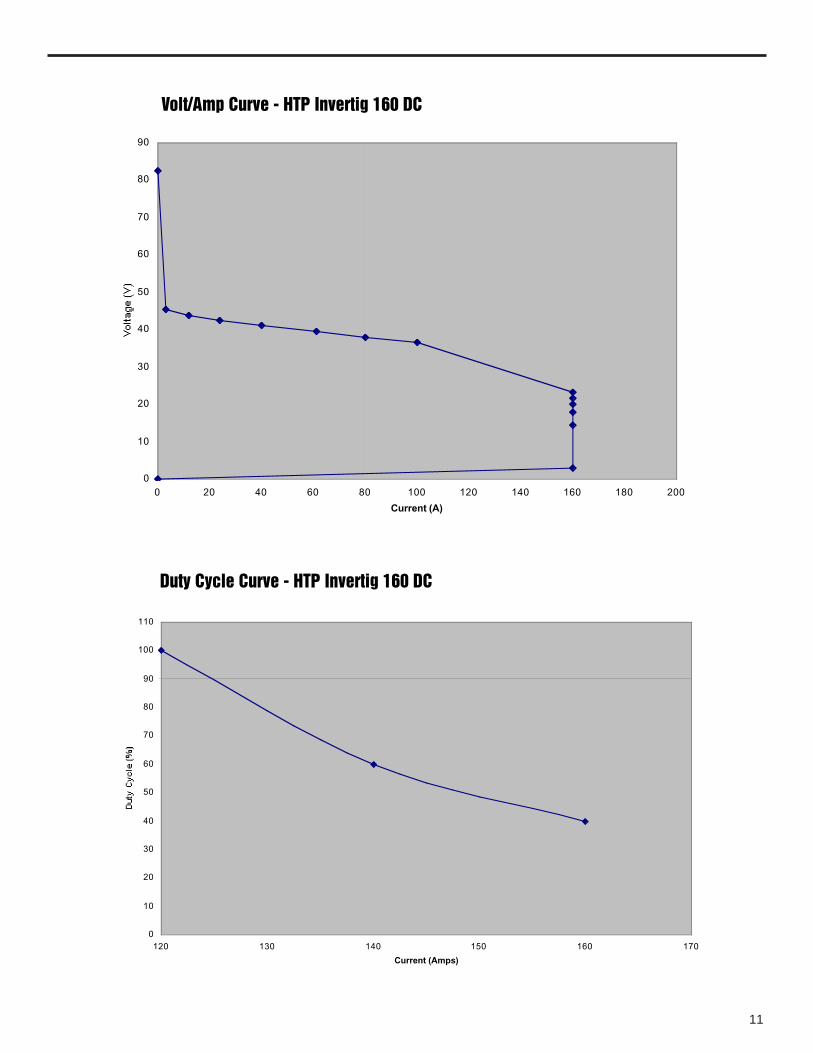
Volt/Amp Curve - HTP Invertig 160 DC
Duty Cycle Curve - HTP Invertig 160 DC
0
10
20
30
40
50
60
70
80
90
100
110
120 130 140 150 160 170
Current (Amps)
Du
ty C
ycle
(%
)
12
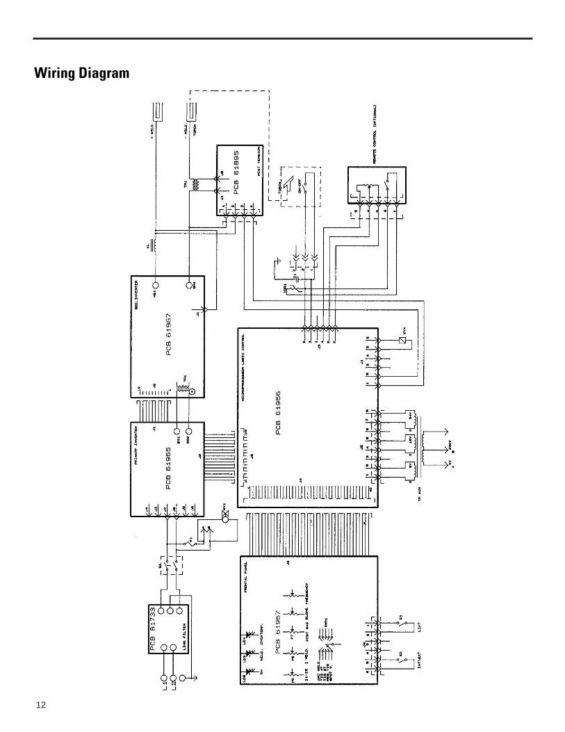
Wiring Diagram

13
Tungsten DiameterIllus # Description 0.040" 1/16" 3/32" 1/8"
Standard Configuration1 Alumina Nozzle 10N49 10N48 10N47 10N462 Collet Body 10N30 10N31 10N32 10N283 Collet 10N22 10N23 10N24 10N25
Gas Lens Configuration (optional)1A Alumina Nozzle 54N17 54N16 54N15 54N142A Gas Lens Collet Body 45V24 45V25 45V26 45V273 Collet 10N22 10N23 10N24 10N25
Short Configuration (optional)1B Alumina Nozzle 13N08 13N09 13N10 13N112B Collet Body 17CB20 17CB20 17CB20 17CB203B Collet 13N21 13N22 13N23 13N24
Following parts fit all tungsten diameters4 Cup Gasket (Std& Short) 300HS
Cup Gasket (Gas Lens) 3GHS5 Torch Head SR-175A Flexible Torch Head SR-17F6 O-Ring 300R7 Short Back Cap 300S7A Medium Back Cap 300M7B Long Back Cap 300L8 Handle 17HR
17 Series Air-Cooled Tig Torch Parts Breakdown

14
Pyrex Cup KitsNothing makes welding easier than being able to see whatyou are doing. HTP’s Pyrex Cup kits do just that! The clearPyrex cup gives you unparalleled visibility of the arc andwork. The Pyrex Cup kit also comes standard with ourspecial gas saver gas lens kit. This unique system saves gaswhile at the same time providing better gas coverage with amore even and uniform gas flow. Eliminates gas turbulencewhich can cause weld quality problems. Pyrex cup kits areavailable to fit all standard torches. There is even a speciallarge diameter kit available for welding titanium.
Large Diameter Pyrex Cup Kits
Tungsten DiameterIllus # Description 0.040" 1/16" 3/32" 1/8" Price
9 and 20 Series Tig Torches1 Heat Shield 2HSGSLD 2HSGSLD 2HSGSLD 2HSGSLD2 Wedge Collet PYR20C040 PYR20C116 PYR20C332 PYR20C183 Collet Body PYR20LDCB PYR20LDCB PYR20LDCB PYR20LDCB4 Tungsten Adapter PYR040TA-LD PYR116TA-LD PYR332TA-LD PYR18TA-LD5 Pyrex Cup PYR20LD PYR20LD PYR20LD PYR20LD
Complete Kit PYREX20LD-040 PYREX20LD-116 PYREX20LD-332 PYREX20LD-18
17, 18, and 26 Series Tig Torches1 Heat Shield 4HSGSLD 4HSGSLD 4HSGSLD 4HSGSLD2 Wedge Collet PYR17SC040 PYR17SC116 PYR17SC332 PYR17SC183 Collet Body PYR17LDCB PYR17LDCB PYR17LDCB PYR17LDCB4 Tungsten Adapter PYR040TA-LD PYR116TA-LD PYR332TA-LD PYR18TA-LD5 Pyrex Cup PYR17LD PYR17LD PYR17LD PYR17LD
Complete Kit PYREX17LD-040 PYREX17LD-116 PYREX17LD-332 PYREX17LD-18
Pyrex-Big Parts
Pyrex Parts

15
Tungsten DiameterIllus # Description 0.040" 1/16" 3/32" 1/8" Price
For 9 and 20 Tig Torches1 Pyrex Cup PYR8S PYR8S PYR8S PYR8S2 Tungsten Adapter PYR040TA PYR116TA PYR332TA PYR18TA3 Collet Body PYR20CB PYR20CB PYR20CB PYR20CB4 Wedge Collet PYR20C040 PYR20C116 PYR20C332 PYR20C185 Heat Shield 2HSGS 2HSGS 2HSGS 2HSGS
Complete Kit PYREX20-040 PYREX20-1/16 PYREX20-3/32 PYREX20-1/8
For 17, 18, and Series 26 Tig Torches
Short Configuration1 Pyrex Cup PYR8S PYR8S PYR8S PYR8S2 Tungsten Adapter PYR040TA PYR116TA PYR332TA PYR18TA3A Collet Body PYR17SCB PYR17SCB PYR17SCB PYR17SCB3A Wedge Collet PYR17SC040 PYR17SC116 PYR17SC332 PYR17SC185A Heat Shield 3HSGS 3HSGS 3HSGS 3HSGS
Complete Kit PYREX17S-040 PYREX17S-1/16 PYREX17S-3/32 PYREX17S-1/8
Standard Configuration1B Pyrex Cup PYR8L PYR8L PYR8L PYR8L2 Tungsten Adapter PYR040TA PYR116TA PYR332TA PYR18TA3B Collet Body PYR17LCB PYR17LCB PYR17LCB PYR17LCB4B Wedge Collet PYR17LC040 PYR17LC116 PYR17LC332 PYR17LC185A Heat Shield 3HSGS 3HSGS 3HSGS 3HSGS
Complete Kit PYREX17-040 PYREX17-1/16 PYREX17-3/32 PYREX17-1/8
Pyrex Cup Parts

16
Trouble Shooting Guide - HTP Invertig 160 DC
Visually check the inside of the machine.Are there burnt or swollen parts? YES
Which kind of problems do youhave after turning on?
NO
Replace the PCB whichhas damaged
component
Turn on themachine
The fan doesn'twork
Is there 230 Vac onfan terminals?
YES
NO
The fan is broken.Replace it
Is the fuse F1ok?
Replacethe fuse F1NO
No leds are lit onthe front of the
machine
Machine is set upfor stick welding,
yellow led is not litand 2 green ledslit, but there is no
output voltage
Machine hasoutput voltage but
you can't adjustthe current
Yellow led isalways lit
In TIG welding thearc doesn't turn
on by pressing thefoot pedal
Solenoid valve orHF doesn't work
Tough start
Not enoughenergy on HF
Is there 230 Vacvoltage on input
switch?
YES
Replaceswitch
YES
Is there 230 Vacvoltage on input
main filter?
NO
Is there 230 Vacvoltage on input
main voltagecable?
NO
Replacemain filter
Replace themain voltage
cable
YES
YES
The fault is onthe plug
NO
A
Go to theB point
Go to theE point
Go to theD point
Go to theC point
Go to theB point
Go to theF point
H
Set up output no-load voltage to95V through the trimmer R57 on
PCB 3 of the front panel
17
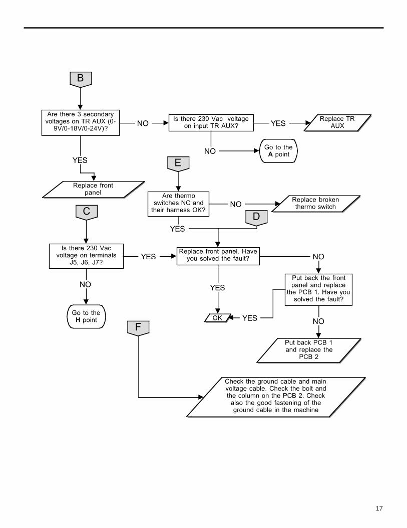
B
Are there 3 secondaryvoltages on TR AUX (0-
9V/0-18V/0-24V)?
Is there 230 Vac voltageon input TR AUX?
Replace TRAUX
Replace frontpanel
YES
NO YES
NO Go to theA point
C
Is there 230 Vacvoltage on terminals
J5, J6, J7?
Replace front panel. Haveyou solved the fault?
Put back the frontpanel and replace
the PCB 1. Have yousolved the fault?
YES NO
Put back PCB 1and replace the
PCB 2
NO
YES
YESOKGo to the
H point
NO
E
Are thermoswitches NC and
their harness OK?
YES
Replace brokenthermo switchNO
F
Check the ground cable and mainvoltage cable. Check the bolt andthe column on the PCB 2. Check
also the good fastening of theground cable in the machine
D

18
Part List

19
1 Handle 661123 Outer Cover 624174 Front Panel Assy 6100175 PCB Logic µP 619566 PCB Front Plate 619577 Hex Stud 631308 Front Panel Label 6603149 Switch 6415610 Knob (29mm Dia) 6620811 Knob (15mm Dia) 6608112 Front Panel 6242013 Peg 6617314 Inductance 6140815 Front Label 66031316 Insulating support 6679717 Connection Plate 66015518 Female Dinse Socket 6427419 3-pin Male Connector 6446720 Male 1/4 BSP Gas Fitting 63197
21 5-pin Male Connector 6446622 Base 6241423 PCB Secondary Power 6196724 Power Cable 6164925 Thermostat 80°C 6577526 Cooling Fan 6418227 Cable Clamp 6606128 Grille 6609829 Knob for Switch 6623130 On-Off Switch 6403131 Auxiliary Transformer 6590832 Solenoid Valve 6410233 PCB HF 6189534 PCB HF Support Bracket 6241935 Step-up Transformer 6184536 Gas Hose 6616037 PCB Primary Power 6196638 Side Label 660312
Invertig 160DC Accessories
Part # Description
60546 Invertig 160DC - Power source only70200-FP Foot Pedal - 25'70200-HC Hand Control - 25' w/velcro straps70200-CART CartSR17-25 25' SR17 Super Flex Tig TorchSR17-12.5 12 1/2' SR17 Super Flex Tig Torch22313 Male Dinse Connection22315-ARC 15' Electrode Holder22311 10' Ground Cable Complete22311-15 15' Ground Cable Complete64465 5 Pin Male Plug500.0082 1/4 BSP Female Gas Nut500.0112 Nipple for above (must be ordered together)

20
Specifications
Invertig 160DC #70160DC
Input Voltage 110 volts 230 volts
Input Amperage 30 amps 18 amps
Amperage Range 5-130 amps 5-160 amps
Duty Cycle 60%@130 amps 40%@160 amps
100%@120 amps 100%@120 amps
No Load Voltage 90 volts
Welding Voltage 10 – 16.4 volts
Arc Force 35%
Hot Start 35%
Slope Down 0.3 – 6.0 sec
Pre Gas 0.5 sec
Post Gas 3 – 20 sec
Pulsing Frequency 0.5 to 300 Hz
Final Current 10% to 90%
Spot Welding Time 0.3 – 6.0 sec
Torch Length & Type WP-17 – 25’
Foot Pedal Length 25’
Weight 32 lbs.
Dimensions 16"L x 12 _W x 8"H