Inverted V Design High Quality Aluminum Construction Compact Design ... · High Quality Aluminum...
12
Inverted V Design High Quality Aluminum Construction Compact Design Ease of Assembly Moving Electrification Forward Engineered Conductor System HVBar
-
Upload
nguyendiep -
Category
Documents
-
view
221 -
download
0
Transcript of Inverted V Design High Quality Aluminum Construction Compact Design ... · High Quality Aluminum...

Inverted V Design
High Quality Aluminum Construction
Compact Design
Ease of Assembly
Moving Electrification Forward
Engineered Conductor SystemHVBar
Features• High current capacity aluminum
extrusion with excellent chemical resistance properties
• Highly rigid cross-sectional geometry resists bending and twisting and permits hangar spacing up to 7 feet
• Systems are engineered to customer specifications, including system layout and installation support
• V shaped interface provide large contact area and collector tracking for efficient current collection
• Full range of standard components including hangers, anchors, feeders, splice joints fixed expansion joints and isolation joints
• Multiple collector configurations available
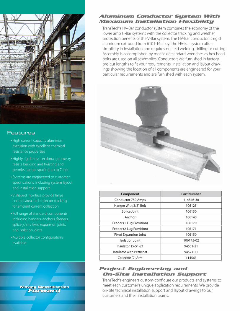
Aluminum Conductor System With Maximum Installation Flexibility
TransTech’s HV-Bar conductor system combines the economy of the lower amp H-Bar systems with the collector tracking and weather protection benefits of the V-Bar system. The HV-Bar conductor is rigid aluminum extruded from 6101-T6 alloy. The HV-Bar system offers simplicity in installation and requires no field welding, drilling or cutting. Assembly is accomplished by means of standard wrenches as hex head bolts are used on all assemblies. Conductors are furnished in factory pre-cut lengths to fit your requirements. Installation and layout draw-ings showing the location of all components are engineered for your particular requirements and are furnished with each system.
Component Part Number
Conductor 750 Amps 114546-30
Hanger With 3/8" Bolt 106125
Splice Joint 106130
Anchor 106140
Feeder (1-Lug Provision) 106170
Feeder (2-Lug Provision) 106171
Fixed Expansion Joint 106150
Isolation Joint 106145-02
Insulator 15-51-21 94551-21
Insulator With Petticoat 94571-21
Collector (2) Arm 114563
Project Engineering andOn-Site Installation SupportTransTech’s engineers custom-configure our products and systems to meet each customer’s unique application requirements. We provide on-site technical installation support and layout drawings to our customers and their installation teams.
Aluminum Inverted HV-Bar
1
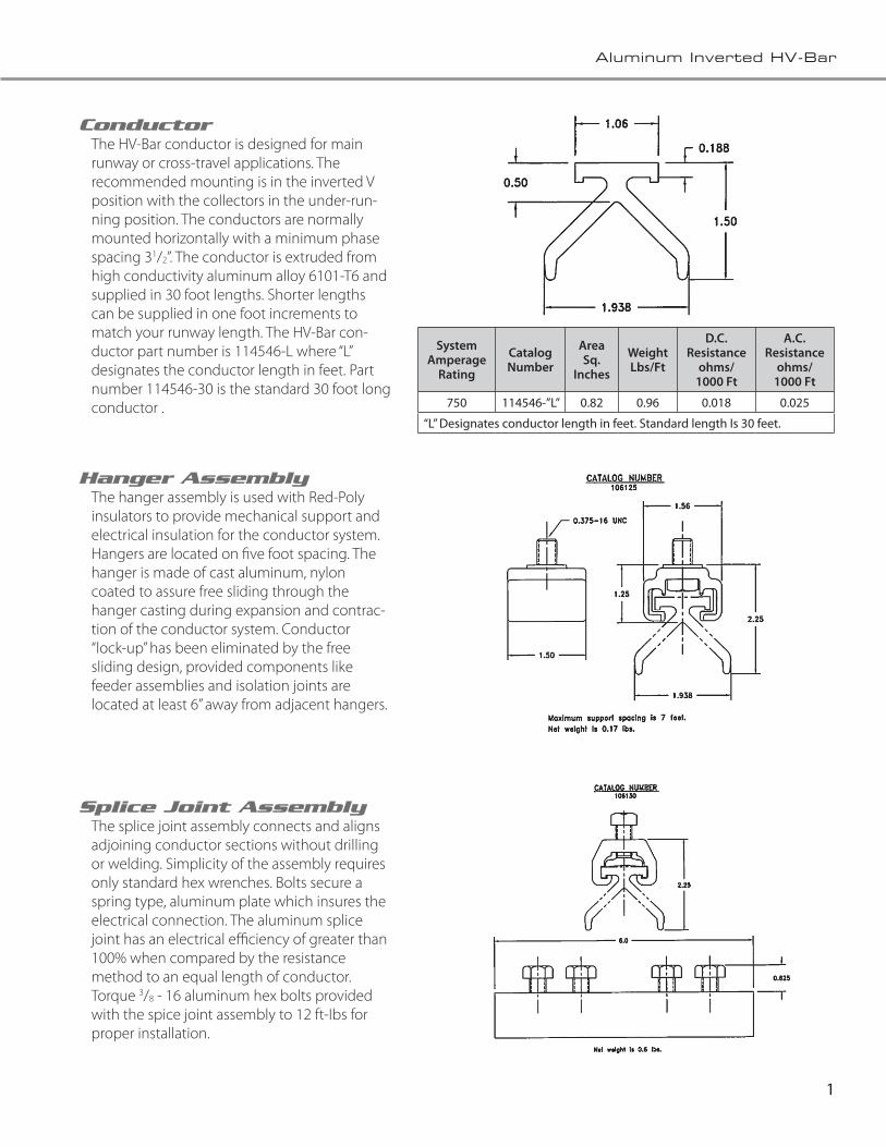
ConductorThe HV-Bar conductor is designed for main runway or cross-travel applications. The recommended mounting is in the inverted V position with the collectors in the under-run-ning position. The conductors are normally mounted horizontally with a minimum phase spacing 31/2”. The conductor is extruded from high conductivity aluminum alloy 6101-T6 and supplied in 30 foot lengths. Shorter lengths can be supplied in one foot increments to match your runway length. The HV-Bar con-ductor part number is 114546-L where “L” designates the conductor length in feet. Part number 114546-30 is the standard 30 foot long conductor .
System Amperage
Rating
Catalog Number
Area Sq.
Inches
Weight Lbs/Ft
D.C. Resistance
ohms/1000 Ft
A.C. Resistance
ohms/1000 Ft
750 114546-”L” 0.82 0.96 0.018 0.025
“L” Designates conductor length in feet. Standard length Is 30 feet.
Hanger AssemblyThe hanger assembly is used with Red-Poly insulators to provide mechanical support and electrical insulation for the conductor system. Hangers are located on five foot spacing. The hanger is made of cast aluminum, nylon coated to assure free sliding through the hanger casting during expansion and contrac-tion of the conductor system. Conductor “lock-up” has been eliminated by the free sliding design, provided components like feeder assemblies and isolation joints are located at least 6” away from adjacent hangers.
Splice Joint AssemblyThe splice joint assembly connects and aligns adjoining conductor sections without drilling or welding. Simplicity of the assembly requires only standard hex wrenches. Bolts secure a spring type, aluminum plate which insures the electrical connection. The aluminum splice joint has an electrical efficiency of greater than 100% when compared by the resistance method to an equal length of conductor. Torque 3/8 - 16 aluminum hex bolts provided with the spice joint assembly to 12 ft-Ibs for proper installation.
2
Aluminum Inverted HV-Bar
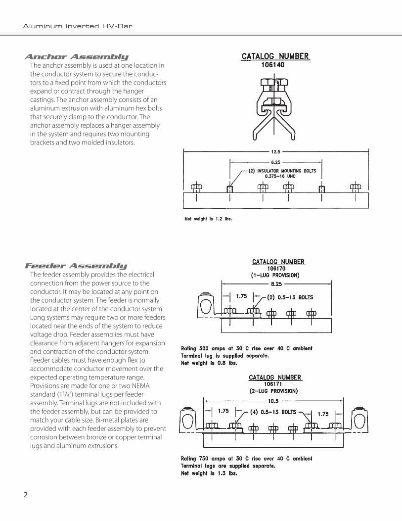
Feeder AssemblyThe feeder assembly provides the electrical connection from the power source to the conductor. It may be located at any point on the conductor system. The feeder is normally located at the center of the conductor system. Long systems may require two or more feeders located near the ends of the system to reduce voltage drop. Feeder assemblies must have clearance from adjacent hangers for expansion and contraction of the conductor system. Feeder cables must have enough flex to accommodate conductor movement over the expected operating temperature range. Provisions are made for one or two NEMA standard (13/4”) terminal lugs per feeder assembly. Terminal lugs are not included with the feeder assembly, but can be provided to match your cable size. Bi-metal plates are provided with each feeder assembly to prevent corrosion between bronze or copper terminal lugs and aluminum extrusions.
Anchor AssemblyThe anchor assembly is used at one location in the conductor system to secure the conduc-tors to a fixed point from which the conductors expand or contract through the hanger castings. The anchor assembly consists of an aluminum extrusion with aluminum hex bolts that securely clamp to the conductor. The anchor assembly replaces a hanger assembly in the system and requires two mounting brackets and two molded insulators.

3
Aluminum Inverted HV-Bar
Isolation Joint AssemblyThe isolation joint assembly is used to insulate one section of the conductor from an adjacent section without interfering with collector travel. It allows portions of the system to be electrically discon-nected while operations continue on the other sections of the conductor system. When more than one crane is operating on the conductor system, the isolation joint is used to create a maintenance area or repair bay. The isolation joint can be inserted at any place in the conductor system. Usually the isolation joints are located 30 feet from each end and replace the last splice assembly on each end of the conductor system. Normally the maintenance area or repair bay is fed electrically through a disconnect switch attached to feeder assemblies on either side of the isolation joint assembly. This arrangement allows for electrical power to be disconnected and “locked out” at a location near the maintenance area or repair bay.
Fixed Expansion Joint Assembly
The expansion joint assembly is necessary on long runways where expansion and contraction of the conductors exceed limits set by TransTech. Normal indoor installations do not require expansion joints if the temperature ranges do not exceed 80 degrees F. Conductor systems longer than 500 feet or systems with extreme temperature variations may require expansion joints.
The conductor gap setting is based on the ambi-ent temperature at the time of installation and the expected temperature variation to which the system will be exposed. At the coolest ambient temperature the gaps must not exceed the maxi-mum expansion gap setting of 11/2 inches. At the hottest ambient and operating temperatures the expansion gap should be nearly closed. Electrical continuity during expansion and contraction is maintained through flexible copper shunts. Copper shunts are separated from the aluminum extrusion with bi-metal plates.
Mounting the fixed expansion joint assembly requires two mounting brackets and two molded insulators.

4
Aluminum Inverted HV-Bar
Mechanical Properties 9455121 9457121
Tensile Strength 3,500 pounds 3.500 pounds
Cantilever Strength 3,000 Inch-pounds 3,000 Inch-pounds
Torsional Strength 600 Inch-pounds 600 Inch-pounds
Weight 0.46 pounds 0.61 pounds
Electrical Properties 9455121 9457121
Dielectric Strength - Dry 38 kV 38 kV
Dew Flashover Strength 15 kV 22 kV
Creep Distance 2.5 Inches 3.6 Inches
Double Arm Collector HV-Bar
Catalog Number - 114563
Collector Ratings
Temp. Rise Current Rating
30˚ C 400 Amps
40˚ C 500 Amps
Note: Collector Horizontal Misalignment is + 2”
9455121
9457121
Red-Poly InsulatorThe Red-Poly insulators are molded fiberglass reinforced polyester material with superior me-chanical strength, excellent electrical characteris-tics, flame retardant, self extinguishing and track resistant. Red-Poly insulators are manufactured in a variety of styles and heights to match your voltage and application requirements. Red-Poly insulator 15-51-21 is used for most applications.

5
Aluminum Inverted HV-Bar
6
Aluminum Inverted HV-Bar
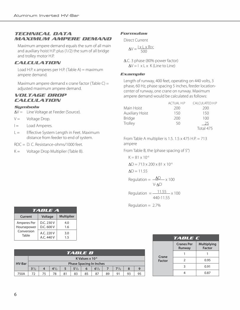
TECHNICAL DATAMAXIMUM AMPERE DEMAND
Maximum ampere demand equals the sum of all main and auxiliary hoist H.P. plus (1/2) the sum of all bridge and trolley motor H.P.
CALCULATION
Load H.P. x amperes per H.P. (Table A) = maximum ampere demand.
Maximum ampere demand x crane factor (Table C) = adjusted maximum ampere demand.
VOLTAGE DROP CALCULATIONSymbolsDV = Line Voltage at Feeder (Source).
V = Voltage Drop.
I = Load Amperes.
L = Effective System Length in Feet. Maximum distance from feeder to end of system.
RDC = D. C. Resistance-ohms/1000 feet.
K = Voltage Drop Multiplier (Table B).
Formulas
Direct Current
DV = I x L x RDC 500
D.C. 3 phase (80% power factor) DV = I x L x K (Line to Line)
Example
Length of runway, 400 feet, operating on 440 volts, 3 phase, 60 Hz, phase spacing 5 inches, feeder location-center of runway, one crane on runway. Maximum ampere demand would be calculated as follows:
ACTUAL H.P CALCULATED H.P Main Hoist 200 200Auxiliary Hoist 150 150Bridge 200 100Trolley 50 25 Total 475
From Table A multiplier is 1.5. 1.5 x 475 H.P. = 713 ampere
From Table B, the (phase spacing of 5”)
K = 81 x 10-6
DD = 713 x 200 x 81 x 10-6
DD = 11.55
Regulation = DD x 100 V-DD
Regulation = 11.55 x 100 440-11.55
Regulation = 2.7%
TABLE C
CraneFactor
Cranes Per Runway
Multiplying Factor
1 1
2 0.95
3 0.91
4 0.87
TABLE B
HV-BarK Values x 10-6
Phase Spacing In Inches31/2 4 41/2 5 51/2 6 61/2 7 71/2 8 9
750A 72 75 78 81 83 85 87 89 91 93 95
TABLE ACurrent Voltage Multiplier
Amperes Per Hoursepower
Conversion Table
D.C. 230 VD.C. 600 V
4.01.6
A.C. 220 VA.C. 440 V
3.01.5

7
Aluminum Inverted HV-Bar
Notes
___________________________________________________________________________________________________________
___________________________________________________________________________________________________________
___________________________________________________________________________________________________________
___________________________________________________________________________________________________________
___________________________________________________________________________________________________________
___________________________________________________________________________________________________________
___________________________________________________________________________________________________________
___________________________________________________________________________________________________________
___________________________________________________________________________________________________________
___________________________________________________________________________________________________________
___________________________________________________________________________________________________________
___________________________________________________________________________________________________________
___________________________________________________________________________________________________________
___________________________________________________________________________________________________________
___________________________________________________________________________________________________________
___________________________________________________________________________________________________________
___________________________________________________________________________________________________________
___________________________________________________________________________________________________________
___________________________________________________________________________________________________________
___________________________________________________________________________________________________________
___________________________________________________________________________________________________________
The Fandstan Electric Companies
TransTechPiedmont, SC USA
Fandstan Electric GroupLondon, England
AKAPP-StemmannBarneveld, Holland
AustbreckVictoria, Australia
Stemmann PolskaWroclaw, Poland
Stemmann TecknikSchuttorf, Germany
Brecknell Willis Composites
Chard Somerset, England
Brecknell WillisChard Somerset, England
Brecknell WillisTainjin, China
Brecknell WillisTaipei, Taiwan
▼▼▼▼
▼▼▼▼▼▼▼
▼▼▼▼▼▼▼▼
▼▼▼▼▼▼▼
▼▼▼▼
Fandstan Electric GroupThe Fandstan Electric Group specializes in engineering solutions for the supply of electrical power and data to moving objects, both linear and rotary. Applications are as wide ranging as public mass transit, mobile cranes, industrial equipment, robots and wind turbines. The Group’s Knowledge of the electrical interface is unrivalled. Fandstan is an independent, privately owned, electrical engineering group with major subsidiaries in Europe, America, Asia (including China) and Australia. The Group, which was founded in 1979, has grown both organically and by acquisition and now employs over 700 people, manufactures across four continents and sells throughout the world. The global positioning of the companies within the Group enables Fandstan Electric to supply close support to the customer and operator.

709 Augusta Arbor Way
Piedmont, SC 29673 A Fandstan Electric Company
800.245.4552 ph | 864.422.9027 fx
transtech.com
The Leaders In Power Transfer TechnologyTransTech is a subsidiary of Fandstan Electric, a global group of companies focusing on energy transfer systems with installations in over 100 countries. Working synergistically with our European sister companies such as Brecknell-Willis, Stemmann and AKAPP, we are able to leverage a broad product portfolio and a wealth of technical expertise. Our goal is to better serve our power transfer markets by continuing to provide solutions that improve product life, performance, and reliability.
04.2010