
INVERTED LIFT SYSTEM FOR BOX ENCLOSUREcdn.futureautomation.co.uk/Tech/i-lsl-efa1-tech.pdf · This...
8
WWW.FUTUREAUTOMATION.NET I-LSL-EFA 1 TECHNICAL SHEET ISSUE 004 SHEET 1 INVERTED LIFT SYSTEM FOR BOX ENCLOSURE UK +44 (0) 1438 833577 US +1 (603) 742 9181
Transcript of INVERTED LIFT SYSTEM FOR BOX ENCLOSUREcdn.futureautomation.co.uk/Tech/i-lsl-efa1-tech.pdf · This...

WWW.FUTUREAUTOMATION.NET
I-LSL-EFA 1
TECHNICAL SHEETISSUE 004
SHEET 1
INVERTED LIFT SYSTEM FOR BOX ENCLOSURE
UK +44 (0) 1438 833577 US +1 (603) 742 9181
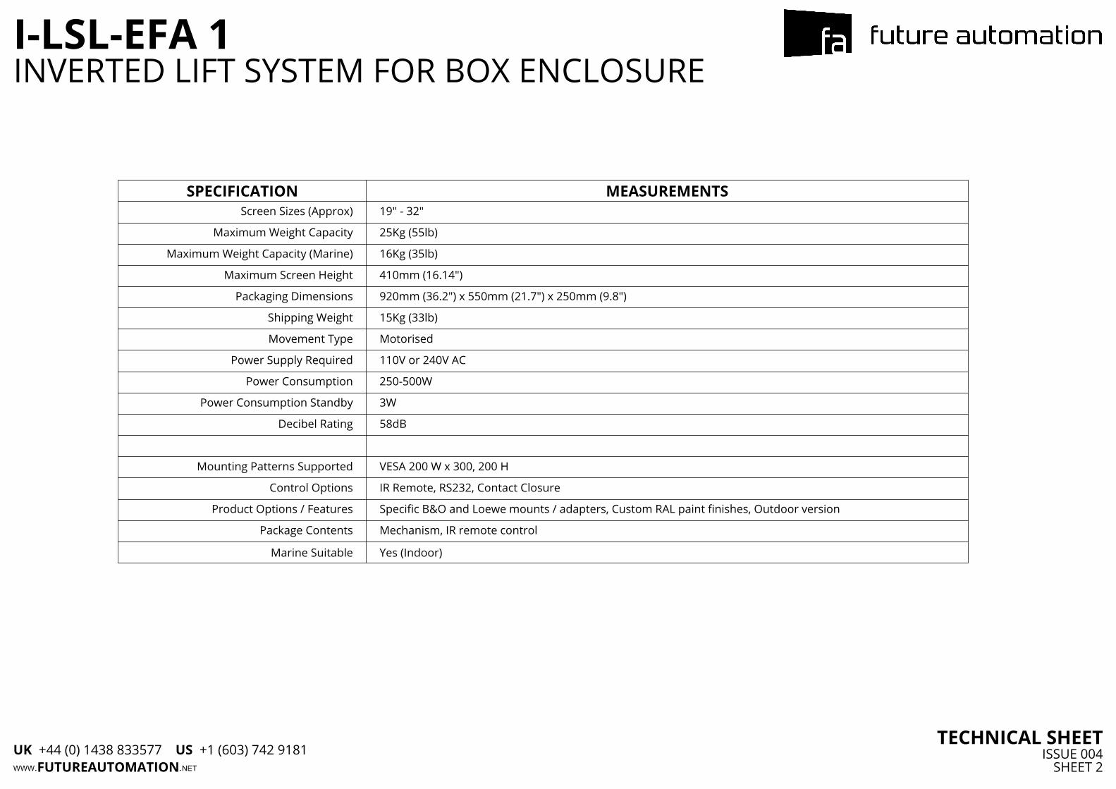
SPECIFICATION MEASUREMENTSScreen Sizes (Approx) 19" - 32"
Maximum Weight Capacity 25Kg (55lb)
Maximum Weight Capacity (Marine) 16Kg (35lb)
Maximum Screen Height 410mm (16.14")
Packaging Dimensions 920mm (36.2") x 550mm (21.7") x 250mm (9.8")
Shipping Weight 15Kg (33lb)
Movement Type Motorised
Power Supply Required 110V or 240V AC
Power Consumption 250-500W
Power Consumption Standby 3W
Decibel Rating 58dB
Mounting Patterns Supported VESA 200 W x 300, 200 H
Control Options IR Remote, RS232, Contact Closure
Product Options / Features Specific B&O and Loewe mounts / adapters, Custom RAL paint finishes, Outdoor version
Package Contents Mechanism, IR remote control
Marine Suitable Yes (Indoor)
WWW.FUTUREAUTOMATION.NET
I-LSL-EFA 1
TECHNICAL SHEETISSUE 004
SHEET 2
INVERTED LIFT SYSTEM FOR BOX ENCLOSURE
UK +44 (0) 1438 833577 US +1 (603) 742 9181

5.9150
8.1207
2.050
A
To MainsPower
Cable Track
CABLE ROUTINGScreen cables are routed behind the Base Panel and out the right side of the Beam into the Cable Track. Cables must be routed carefully to prevent any interference with the LSL beam as it operates.
Screen and Mechanism cables should be routed to a control box in the bottom of the cabinet.
WWW.FUTUREAUTOMATION.NET
I-LSL-EFA 1
TECHNICAL SHEETISSUE 004
SHEET 3
INVERTED LIFT SYSTEM FOR BOX ENCLOSURE
UK +44 (0) 1438 833577 US +1 (603) 742 9181

22.8580
InternalCabinetHeight
Internal Cabinet Width = Screen Width + 460 [18.1]for EFA Orientation as Shown
2.870
0.820
0.820
0.820
Max Thicknessof Base andCabinet Top
13.8350
Required Space for EFA
Orientation
X
X
16.7425Max
ScreenHeight
3.077
Back ofMechanism to
Mount
Y
SECTION X-X
Aperture Depth =Screen Depth + 75 [3.0]
0.614
DETAIL YSCALE 2 : 5
0.820
0.13
MECHANISM UP - IN CABINET
WWW.FUTUREAUTOMATION.NET
I-LSL-EFA 1
TECHNICAL SHEETISSUE 004
SHEET 4
INVERTED LIFT SYSTEM FOR BOX ENCLOSURE
UK +44 (0) 1438 833577 US +1 (603) 742 9181

22.8580
InternalCabinetHeight
5.9150
Minimum ScreenHeight from Base
of Cabinet
0.820
Max Thicknessof Base andCabinet Top
0.820
U
U
16.7425Max
ScreenHeight
3.077
Back ofMechanism
to Mount
SECTION U-U
Aperture Depth =Screen Depth + 75mm [3.0]
Aperture Width = Screen Width + 46mm [1.8]
MECHANISM DOWN - IN CABINET
WWW.FUTUREAUTOMATION.NET
I-LSL-EFA 1
TECHNICAL SHEETISSUE 004
SHEET 5
INVERTED LIFT SYSTEM FOR BOX ENCLOSURE
UK +44 (0) 1438 833577 US +1 (603) 742 9181

0.3R8
1.
435
0.24
Z
Z
7.5190
1.
538
31.1790
0.00
0.615
2.050
Base Depth =Cabinet ApertureDepth -6mm [0.25](Minimum 74 [2.9])
Flap Panel Depth =Cabinet Aperture Depth
- 6mm [0.25]
0.26
AA
SECTION Z-Z
A step is required in the front ofthe Flap to meet a step in thefront edge of the Cabinet Aperture
0.410
0.
1 2
DETAIL AA
AC
DETAIL AC
Flap push rod
Fixing Plate
BASE PANEL & ENCLOSURE LID DETAILSFlap depth dimensions are based on a 3mm thick piano hinge
Required flap dimensions may vary dependant on the hinge used.
WWW.FUTUREAUTOMATION.NET
I-LSL-EFA 1
TECHNICAL SHEETISSUE 004
SHEET 6
INVERTED LIFT SYSTEM FOR BOX ENCLOSURE
UK +44 (0) 1438 833577 US +1 (603) 742 9181

13.78350
Width Required for EFAin Alternative Orientation
EFA orientated as standard(making contact with LSL Beam)
EFA in alternative position
Cable exit point
POSITIONIG THE EFA TO ACCOMADATE SMALLER SCREENSA Base Panel of less than 1050mm [41.3] wide will cause the EFA to interfere with the LSL beam.
This can be avoided by orientating the EFA away from the LSL. It will however require more space for the EFA to be positioned to the side of the cabinet.
WWW.FUTUREAUTOMATION.NET
I-LSL-EFA 1
TECHNICAL SHEETISSUE 004
SHEET 7
INVERTED LIFT SYSTEM FOR BOX ENCLOSURE
UK +44 (0) 1438 833577 US +1 (603) 742 9181

22.8580
7.9200
7.9200
22.7576
BackPlate
Height
5.1130
14.2362
4.8122
OVERALL MECHANISM DIMENSIONSMECHANISM UPMECHANISM DOWN
WWW.FUTUREAUTOMATION.NET
I-LSL-EFA 1
TECHNICAL SHEETISSUE 004
SHEET 8
INVERTED LIFT SYSTEM FOR BOX ENCLOSURE
UK +44 (0) 1438 833577 US +1 (603) 742 9181