Inventor 2016 Sheet Metal Enhancements - Autodesk€¦ · Inventor 2016 Sheet Metal Enhancements...
11
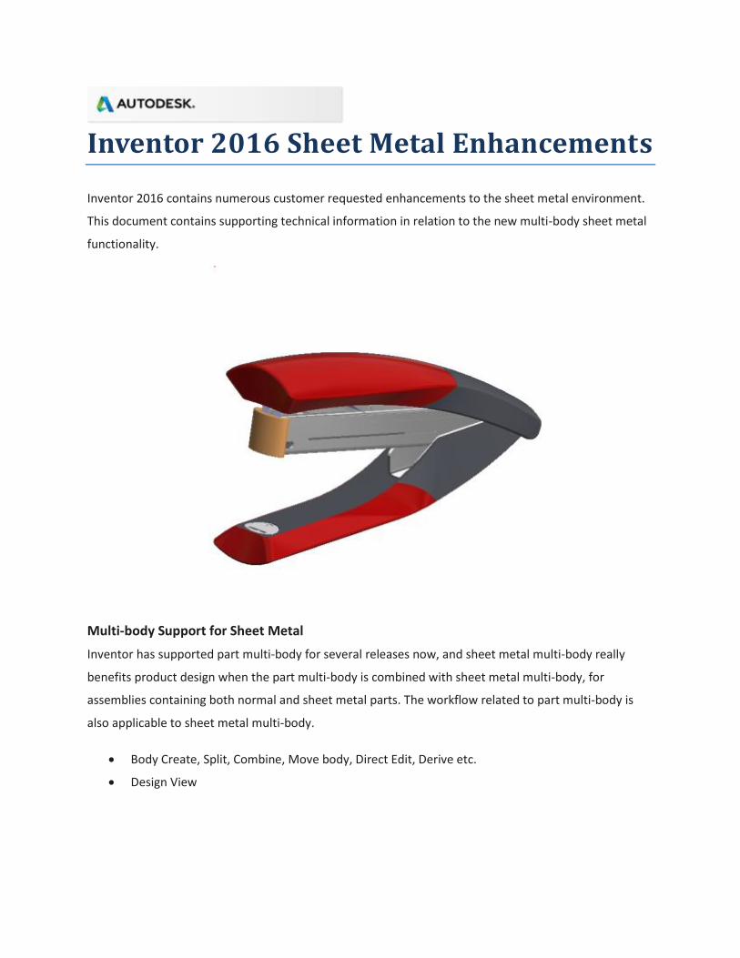
Inventor 2016 Sheet Metal Enhancements Inventor 2016 contains numerous customer requested enhancements to the sheet metal environment. This document contains supporting technical information in relation to the new multi-body sheet metal functionality. Multi-body Support for Sheet Metal Inventor has supported part multi-body for several releases now, and sheet metal multi-body really benefits product design when the part multi-body is combined with sheet metal multi-body, for assemblies containing both normal and sheet metal parts. The workflow related to part multi-body is also applicable to sheet metal multi-body. Body Create, Split, Combine, Move body, Direct Edit, Derive etc. Design View
Transcript of Inventor 2016 Sheet Metal Enhancements - Autodesk€¦ · Inventor 2016 Sheet Metal Enhancements...
Inventor 2016 Sheet Metal Enhancements
Inventor 2016 contains numerous customer requested enhancements to the sheet metal environment.
This document contains supporting technical information in relation to the new multi-body sheet metal
functionality.
Multi-body Support for Sheet Metal
Inventor has supported part multi-body for several releases now, and sheet metal multi-body really
benefits product design when the part multi-body is combined with sheet metal multi-body, for
assemblies containing both normal and sheet metal parts. The workflow related to part multi-body is
also applicable to sheet metal multi-body.
Body Create, Split, Combine, Move body, Direct Edit, Derive etc.
Design View

There are two typical workflows:
1. Designing sheet metal products from scratch in the sheet metal environment.
o Create sheet metal multi-body using
the “New Solid” option in existing
features like Face, Contour Flange,
Contour Roll, Lofted Flange, Split,
and with multi-body workflows for
many others.
o Flat pattern in legacy sheet metal
parts will turn sick when creating a
multi-body sheet metal part.
o Only one A-Side definition can be
created per body.
o Use Make Components and Make
Parts to generate individual sheet
metal .ipt files for each solid body.
The sheet metal style is synced from
the parent to these separate IPTs.
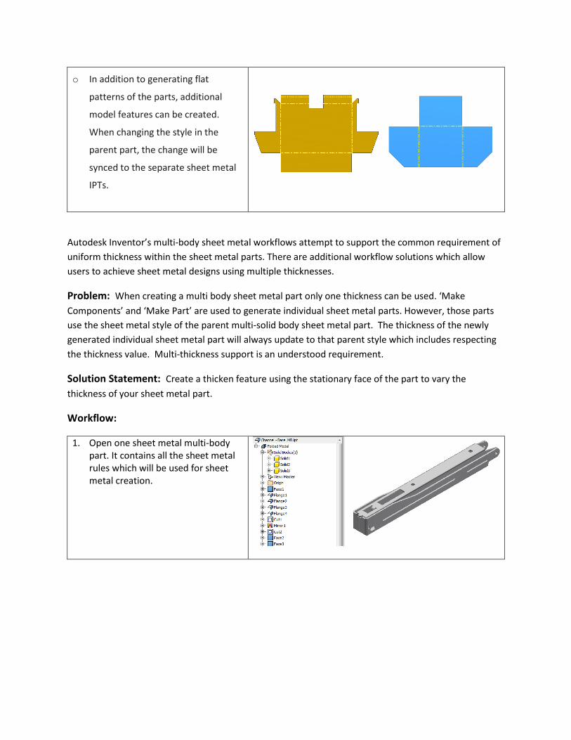
o In addition to generating flat
patterns on the parts, additional
model features can be created.
When changing the style in the
parent part, the change will be
synced to the separate sheet metal
IPT’s.
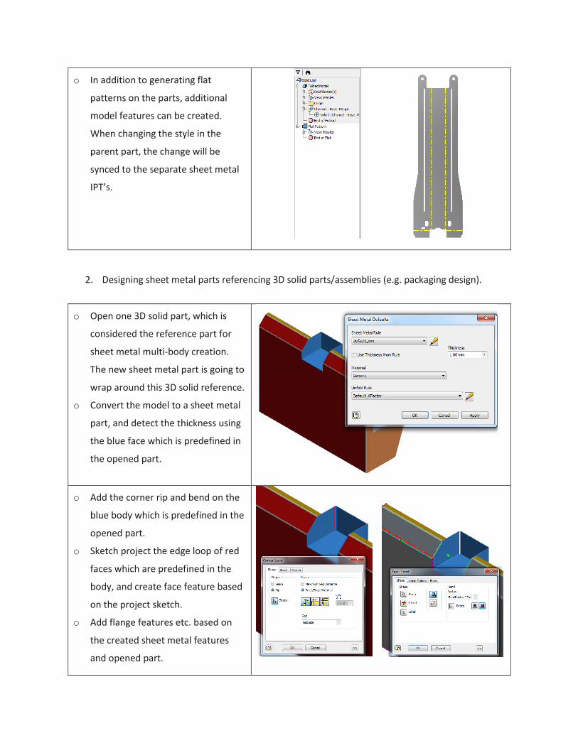
2. Designing sheet metal parts referencing 3D solid parts/assemblies (e.g. packaging design).
o Open one 3D solid part, which is
considered the reference part for
sheet metal multi-body creation.
The new sheet metal part is going to
wrap around this 3D solid reference.
o Convert the model to a sheet metal
part, and detect the thickness using
the blue face which is predefined in
the opened part.
o Add the corner rip and bend on the
blue body which is predefined in the
opened part.
o Sketch project the edge loop of red
faces which are predefined in the
body, and create face feature based
on the project sketch.
o Add flange features etc. based on
the created sheet metal features
and opened part.
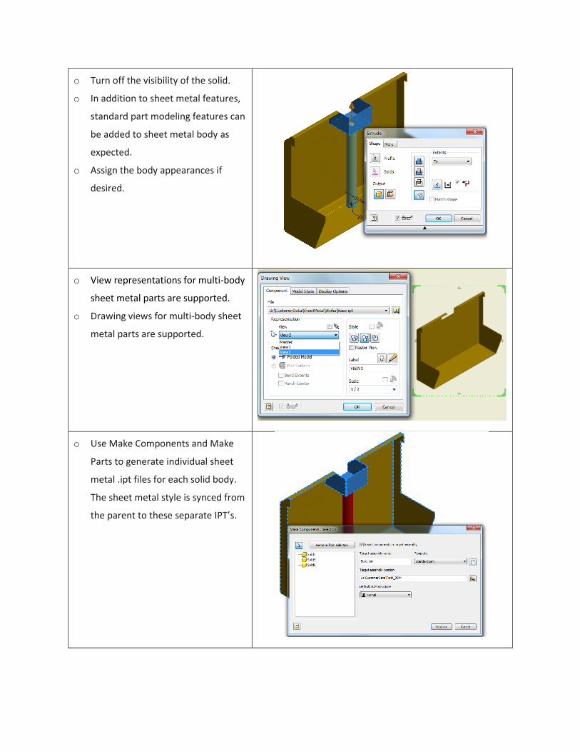
o Turn off the visibility of the solid.
o In addition to sheet metal features,
standard part modeling features can
be added to sheet metal body as
expected.
o Assign the body appearances if
desired.
o View representations for multi-body
sheet metal parts are supported.
o Drawing views for multi-body sheet
metal parts are supported.
o Use Make Components and Make
Parts to generate individual sheet
metal .ipt files for each solid body.
The sheet metal style is synced from
the parent to these separate IPT’s.
o In addition to generating flat
patterns of the parts, additional
model features can be created.
When changing the style in the
parent part, the change will be
synced to the separate sheet metal
IPTs.
Autodesk Inventor’s multi-body sheet metal workflows attempt to support the common requirement of
uniform thickness within the sheet metal parts. There are additional workflow solutions which allow
users to achieve sheet metal designs using multiple thicknesses.
Problem: When creating a multi body sheet metal part only one thickness can be used. ‘Make
Components’ and ‘Make Part’ are used to generate individual sheet metal parts. However, those parts
use the sheet metal style of the parent multi-solid body sheet metal part. The thickness of the newly
generated individual sheet metal part will always update to that parent style which includes respecting
the thickness value. Multi-thickness support is an understood requirement.
Solution Statement: Create a thicken feature using the stationary face of the part to vary the
thickness of your sheet metal part.
Workflow:
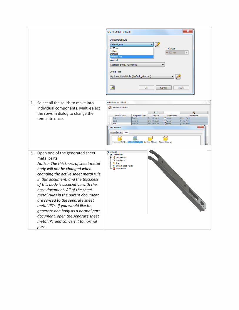
1. Open one sheet metal multi-body part. It contains all the sheet metal rules which will be used for sheet metal creation.
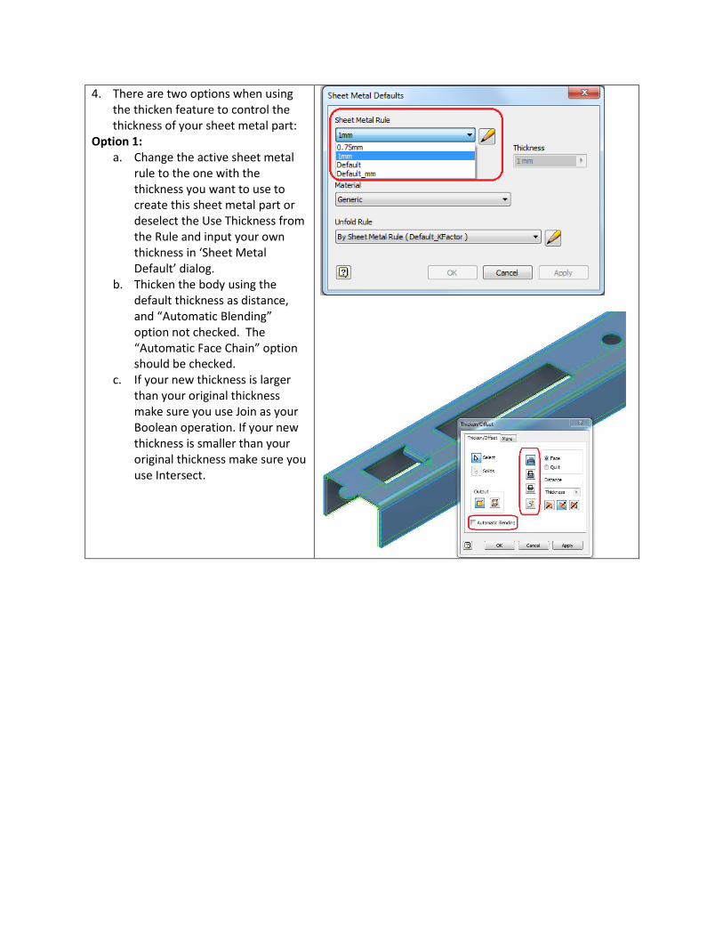
2. Select all the solids to make into individual components. Multi-select the rows in dialog to change the template once.
3. Open one of the generated sheet metal parts. Notice: The thickness of sheet metal body will not be changed when changing the active sheet metal rule in this document, and the thickness of this body is associative with the base document. All of the sheet metal rules in the parent document are synced to the separate sheet metal IPTs. If you would like to generate one body as a normal part document, open the separate sheet metal IPT and convert it to normal part.
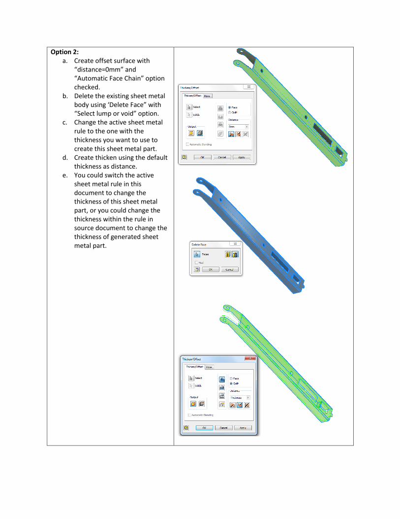
4. There are two options when using the thicken feature to control the thickness of your sheet metal part:
Option 1: a. Change the active sheet metal
rule to the one with the thickness you want to use to create this sheet metal part or deselect the Use Thickness from the Rule and input your own thickness in ‘Sheet Metal Default’ dialog.
b. Thicken the body using the default thickness as distance, and “Automatic Blending” option not checked. The “Automatic Face Chain” option should be checked.
c. If your new thickness is larger than your original thickness make sure you use Join as your Boolean operation. If your new thickness is smaller than your original thickness make sure you use Intersect.
Option 2: a. Create offset surface with
“distance=0mm” and “Automatic Face Chain” option checked.
b. Delete the existing sheet metal body using ‘Delete Face” with “Select lump or void” option.
c. Change the active sheet metal rule to the one with the thickness you want to use to create this sheet metal part.
d. Create thicken using the default thickness as distance.
e. You could switch the active sheet metal rule in this document to change the thickness of this sheet metal part, or you could change the thickness within the rule in source document to change the thickness of generated sheet metal part.

5. By thickening this way you link your Sheet Metal Default to your parts thickness. (This was broken when the part was derived from the Multi Solid Body).
6. Now that your part thickness and your Sheet Metal Default thickness are the same a Flat Pattern can be created.
Problem: You are attempting to create a sheet metal design (assembly) accommodating multiple
gauges. For example, the sheet metal parts have similar shape but different gauges.
Solution Statement: Create a user parameter and use it as the key parameter to drive the sheet metal
thickness in your custom iPart.
Workflow:
1. Create sheet metal multi-body part, (see the attached sample part).
2. Create one user parameter named ‘SheetThickess’, and set the user parameter as thickness in sheet metal rule. You can’t select the thickness parameter for iPart column in this case so you need to define one user parameter to drive this.
3. Define one custom property named
‘Type’, and which is used to define the type of gauge. Save the document.
4. Create iPart, select ‘SheetThickness’ and custom property ‘Type’ in the table. Set the ‘Type’ column as custom parameter column.
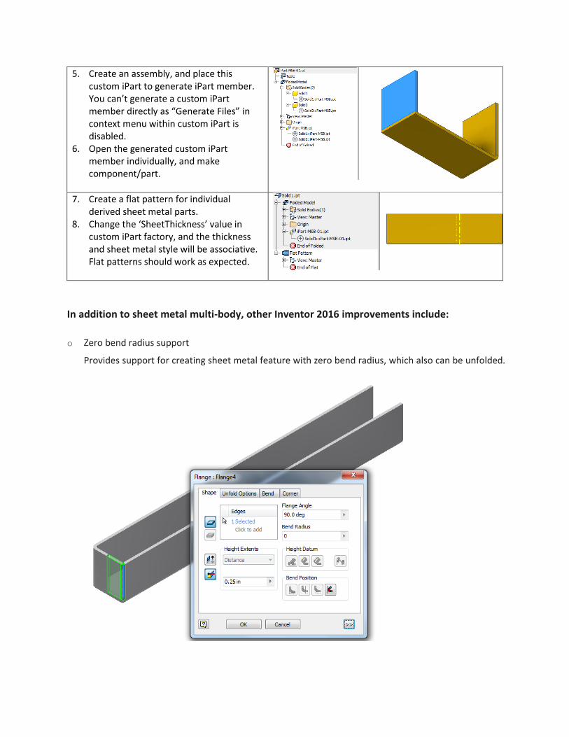
5. Create an assembly, and place this custom iPart to generate iPart member. You can’t generate a custom iPart member directly as “Generate Files” in context menu within custom iPart is disabled.
6. Open the generated custom iPart member individually, and make component/part.
7. Create a flat pattern for individual derived sheet metal parts.
8. Change the ‘SheetThickness’ value in custom iPart factory, and the thickness and sheet metal style will be associative. Flat patterns should work as expected.
In addition to sheet metal multi-body, other Inventor 2016 improvements include:
o Zero bend radius support
Provides support for creating sheet metal feature with zero bend radius, which also can be unfolded.
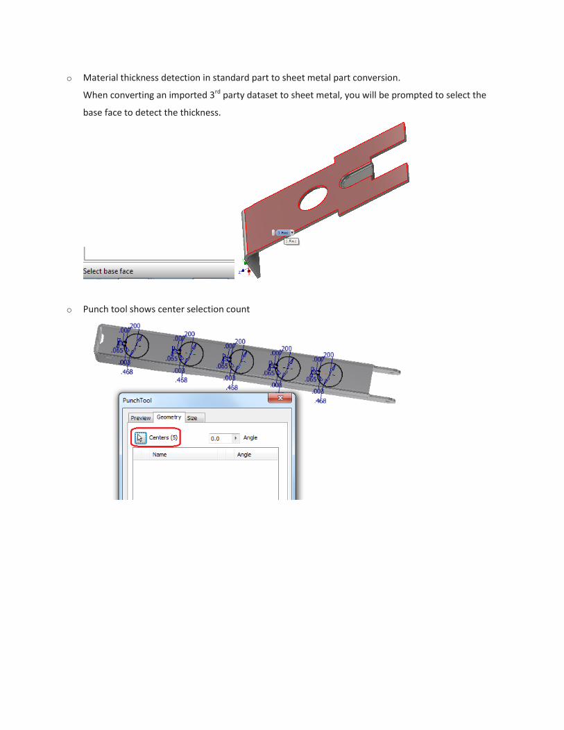
o Material thickness detection in standard part to sheet metal part conversion.
When converting an imported 3rd party dataset to sheet metal, you will be prompted to select the
base face to detect the thickness.
o Punch tool shows center selection count