Influence of Weight-on-Bit on Percussive Drilling Performance
28
Noname manuscript No. (will be inserted by the editor) Influence of Weight-on-Bit on Percussive Drilling Performance Xianfeng Song · Ole Morten Aamo · Pascal-Alexandre Kane · Emmanuel Detournay Received: date / Accepted: date Abstract A phenomenological model for percussive drilling systems is proposed in this paper to explain the experimentally demonstrated existence of an optimal weight-on-bit (WOB), for which the rate of penetration (ROP) is maximized. Sev- eral hypotheses have been previously proposed to explain this universal character- istic of percussive drilling, including increased wear of the bit, reduced indexing, and poor cleaning of debris under excessive WOB. Motivated by experimental evidence, we instead consider an increase of the pseudo-stiffness of the bit-rock interface (BRI) with increasing WOB, and investigate its effect on the impact energy transmitted to the rock. The 1D model approximates the dynamics under- lying the drilling process by assuming that the impact of the hammer generates a longitudinal wave in the bit. It is shown that the BRI pseudo-stiffness influences the incident wave and associated energy transmitted from the bit to the rock. As a consequence, the drilling efficiency is affected by the dependence of the BRI stiffness on the WOB. The model indicates that there exist optimal conditions for the energy transfer from the bit to the rock in terms of the impedance ratio and the BRI stiffness/WOB. Thus it confirms that there is a sweet spot as seen in practice, which suggests that the root cause of the existence of a sweet spot in the ROP-WOB relationship lies in the nature of the BRI laws, rather than with issues related to bit indexing, bit wear, and/or cleaning of the debris. Keywords Percussive drilling · Weight-on-bit · Rate of penetration · Impact transmission efficiency X. Song · O. Aamo Norwegian University of Science and Technology, Trondheim, Norway P. Kane SINTEF Industry, Trondheim, Norway E. Detournay University of Minnesota, Minneapolis, USA Tel.: +1-612-625-3043 Fax.: +1-612-626-7750 E-mail: [email protected]
Transcript of Influence of Weight-on-Bit on Percussive Drilling Performance

Noname manuscript No.(will be inserted by the editor)
Influence of Weight-on-Bit on Percussive DrillingPerformance
Xianfeng Song · Ole Morten Aamo ·Pascal-Alexandre Kane · EmmanuelDetournay
Received: date / Accepted: date
Abstract A phenomenological model for percussive drilling systems is proposedin this paper to explain the experimentally demonstrated existence of an optimalweight-on-bit (WOB), for which the rate of penetration (ROP) is maximized. Sev-eral hypotheses have been previously proposed to explain this universal character-istic of percussive drilling, including increased wear of the bit, reduced indexing,and poor cleaning of debris under excessive WOB. Motivated by experimentalevidence, we instead consider an increase of the pseudo-stiffness of the bit-rockinterface (BRI) with increasing WOB, and investigate its effect on the impactenergy transmitted to the rock. The 1D model approximates the dynamics under-lying the drilling process by assuming that the impact of the hammer generates alongitudinal wave in the bit. It is shown that the BRI pseudo-stiffness influencesthe incident wave and associated energy transmitted from the bit to the rock. Asa consequence, the drilling efficiency is affected by the dependence of the BRIstiffness on the WOB. The model indicates that there exist optimal conditions forthe energy transfer from the bit to the rock in terms of the impedance ratio andthe BRI stiffness/WOB. Thus it confirms that there is a sweet spot as seen inpractice, which suggests that the root cause of the existence of a sweet spot in theROP-WOB relationship lies in the nature of the BRI laws, rather than with issuesrelated to bit indexing, bit wear, and/or cleaning of the debris.
Keywords Percussive drilling · Weight-on-bit · Rate of penetration · Impacttransmission efficiency
X. Song · O. AamoNorwegian University of Science and Technology, Trondheim, Norway
P. KaneSINTEF Industry, Trondheim, Norway
E. DetournayUniversity of Minnesota, Minneapolis, USATel.: +1-612-625-3043Fax.: +1-612-626-7750E-mail: [email protected]

2 Xianfeng Song et al.
1 Introduction
A percussive drilling system, either a Top-Hammer (TH) or a Down-The-Hole(DTH) tool consists essentially of a pneumatically or hydraulically driven ham-mer and a bit assembly, see Fig. 1 for the schematic of a DTH tool. During thepercussive drilling process, the hammering system converts the potential energy ofthe pressurized air or water into reciprocating movements of the hammer, whichrepeatedly impacts the bit assembly [1]. An impact induces a compressive incidentwave that travels through the bit assembly to eventually cause penetration byindentation of a collection of bit buttons into the rock [2, 3].
Debris
Hammer
Bit
Impulsive Load
WOB
LooseDebris
Fig. 1: Schematic of a DTH percussive drilling system.
Percussion tools are generally more efficient for drilling hard rock formationsthan conventional rotary equipment [4, 5]. Their advantages include lower weight-on-bit (WOB) requirement, reduced bit wear due to less contact time with therock, less borehole deviation and larger chip size [6].
As with other mechanical excavation methods [7], rock breakage in percussiondrilling results from penetration of an indenter into rock that causes crushingand the formation of tensile cracks. The produced rock cuttings are then flushedaway from the rock surface by air or water. The rock fragmentation process isenhanced by the rotation of the drilling assembly, which causes the drill buttonsto move between blows, with the subsequent impacts leading to the preferentialdevelopment of lateral cracks [8]. Efficient transmission of the impact energy tothe rock requires closing of the transient gap between the drill bit and rock surfacebefore the next indentation; this is ensured by applying a sufficiently large thrustforce (WOB) on the bit assembly.

Influence of Weight-on-Bit on Percussive Drilling Performance 3
0.5 1 1.5 2WOB [kN]
0
2
4
6
8
10
RO
P [m
m/s
]
Fig. 2: Sweet spot in WOB-ROP response given different rock formations, pneu-matic pressure, and bit types (adapted from [14, 16]). Symbol H pertains to wingedbit drilling of Pink Tennessee marble with a pneumatic pressure of 0.34MPa [14]; , �, F refer to winged bit, Swedish granite, and pneumatic pressure of 0.59MPa,0.49MPa, 0.39MPa respectively [14]; � corresponds to button bit, Charcoal gran-ite, and pneumatic pressure of 0.55MPa [16];
Although pneumatic percussive drilling has been in operation since the 1860’s[7, 9], fundamental knowledge about the complex drilling process with such toolsstill remains somewhat elusive. The lack of understanding has limited the wide-spread application of this technique, in particular to the oil industry [10]. Specif-ically, there is no consensus regarding the root cause of the observed existence ofan optimal state in the control variables. Indeed, many experiments have shownevidence that the average rate of penetration (ROP), the most important indicatorfor drilling performance, can be maximized for certain parameter sets, includingthe static WOB [1, 9, 11–14]. Such an optimal state is typically referred to as a“sweet spot” [15].
Laboratory and field data illustrated in Fig. 2 suggest that such an optimalconfiguration is a universal characteristic of percussive drilling, with the optimalWOB depending on several factors, such as rock formation, bit type, pneumaticpressure, and indexing angle. Nevertheless, a convincing explanation of the physicsbehind the existence of a sweet spot has not yet been proposed, in our opinion. Poorunderstanding of the root cause of this phenomenon is restricting the developmentof adaptive control algorithms to identify the sweet spot to strategies that areexclusively data-driven, without the benefits of insight provided by a mathematicalmodel.
Various hypotheses have been advanced to explain the existence of a sweet spot:increased wear of the bit [17], reduced indexing (including stick-slip) [11, 18], andpoor cleaning of the debris [19, 20]. These explanations, while perhaps applicablein particular cases, do not provide universal rationales, as a significant body ofcontradictory experimental evidence exists.

4 Xianfeng Song et al.
First a possible link between bit wear and the existence of a sweet spot ischallenged by results of field experiments, where the bit was examined and sharp-ened periodically and wear can therefore be assumed to be negligible [9]. In anycase, experiments show that bits with hemispherical buttons hold an exceptionalresistance to abrasive wear [16]. Furthermore, in a series of tests, where the WOBwas progressively increased, it was noted that moderate wear of the carbide insertshad already taken place during the ascending phase of the ROP versus WOB [21].
Decrease of ROP with increasing WOB beyond the optimum has been at-tributed to reduced indexing, presumably caused by the limited torque capacityof the equipment [18]. However, this explanation is contradicted by experimentalresults indicating that the specific energy for drilling granite with a button bit isessentially the same for three different indexing angles [16]. Furthermore, givena nearly constant rotation speed, Schunnesson [22] demonstrated that a higherROP was obtained in a field test by reducing the WOB. Also, experiments con-ducted with different indexing angle [13] indicate that an optimum WOB existsirrespective of the indexing angle.
Finally, poor cleaning can generally be eliminated as a plausible cause to the ex-istence of a sweet spot, since the flushing capacity of modern equipment (especiallyin laboratory experiments) is powerful enough to remove the debris efficiently.
Wiercigroch and co-workers [23–26] have studied the long-term dynamical re-sponse of drifting impact oscillators to explain the drop in ROP with increasingWOB in percussion drilling. Although the model is able to reproduce the opti-mal configurations observed in laboratory experiments, its direct applicability topercussive drilling is open to questions as it is framed in terms of rigid body dy-namics rather than wave propagation and harmonic excitation is used to mimicpercussive activation. Furthermore, an alternative drifting oscillator model basedon a bilinear bit/rock interaction law and an impulsive rather than a harmonicloading could not reproduce an optimal configuration in the explored parametricrange [27].
Instead, we propose a different mechanism behind the sweet spot and presentthe experimental evidence to support it. First we note that the timescales charac-terizing the percussion drilling processes span several orders of magnitude: T1 =O(10−2 ∼ 10−1s) is associated with the impact frequency of the hammer whileT2 = O(∼ 10−4s), corresponds to the pulse length of an impact and also mea-sures the time duration of the bit penetration into the rock [15]. All the previousexplanations for the existence of a sweet spot reviewed above actually involve theslow timescale. However, it is the fast process, responsible for the damage andthe fracturing of the rock, that will eventually determine the drilling performance.Therefore, we propose to analyze the drilling process on the fast time scale. In anutshell, the existence of the sweet spot can be explained by considering the force-penetration (F-P) curve during one impact. This response is strongly nonlinear,mainly due to the presence of a layer of loose rock debris and damaged rock be-tween the drill bit and the intact rock. The interface layer is expected to exhibit alarger resistance to penetration during impact, i.e., a larger pseudo-stiffness, whensubjected to a larger static WOB force.
Therefore, we consider an increase of the pseudo-stiffness of the BRI with theWOB and develop a phenomenological model to investigate its effect on the impactenergy transmitted to the rock. According to the elastodynamic model, there existoptimal contact conditions for maximizing the energy transfer from the bit to the

Influence of Weight-on-Bit on Percussive Drilling Performance 5
rock in terms of the BRI pseudo-stiffness and the impedance ratio. A previousinvestigation by Hustrulid and Fairhurst [14] has already noted that an optimalloading slope of the F-P relation maximizes the energy transmission efficiency.Moreover, parametric studies conducted by Lundberg [28–30] also indicate theexistence of an optimal hammer length, a function of the penetration resistance, forwhich the energy transmission efficiency is maximum. Nonetheless, the dependenceof the pseudo-stiffness of the BRI on the WOB has not yet been suggested as anexplanation for the observed dependance of the ROP on the WOB.
The paper is organized as follows. Section 2 reviews experimental evidenceindicating that the observed WOB-ROP relationship actually reflects the non-monotonic relationship between the BRI pseudo-stiffness and the impact energytransmitted to the rock. Section 3 demonstrates with a 1D phenomenological modelof percussion drilling that there is an optimal BRI pseudo-stiffness to maximize theenergy transfer to the rock, provided that the bit impedance is small compared tothe rock impedance. Section 4 supports the hypothesis that the impedance ratiobetween the bit and the rock is indeed small, on the basis of a finite elementsimulations and analysis of experimental data. Section 5 concludes that the rootcause of the existence of a sweet spot in the ROP-WOB relationship indeed lies inthe nature of the BRI laws.
2 Experimental Evidence
2.1 Preamble
Comprehensive research programs focused on percussion drilling of rock were con-ducted in the 1950’s and 1960’s at several research institutes, including the Uni-versity of Minnesota [8, 13, 18, 31–39]. These efforts have provided valuable in-formation on the influence of the WOB and of the damaged rock underneath thedrill buttons on the drilling performance.
Two types of laboratory tests have been used in the research on percussiondrilling: the drop test and the jackleg-type percussive drilling test. Despite thefundamental differences between the two tests in regard to the fraction of theimpact energy used to drive the bit into the rock [40], the drop test is appealingbecause of its simplicity. Indeed the key factors influencing rock penetration canbe assessed by adjusting the drop mass and geometry or the drop height andmeasuring the difference in the bit kinetic energy before and after impact, as wellas the volume of the craters created by the impact. The main justification forusing a drop test (DT) as a proxy to percussive drilling (PD) comes from theorder of magnitude difference between the penetration time of the bit into therock following an impact and the frequency of the hammer. In other words, thetime elapsed between successive impacts is large enough that each penetrationevent can be considered to be independent regardless of the interactions betweensuccessive indentations [28, 33]. However, the usual drop tests cannot be used tocharacterize the influence the WOB on the drilling performance.
We review the experimental findings in light of our hypothesis that the de-pendence of the BRI pseudo-stiffness on the WOB is the key factor behind theexistence of a sweet spot. In a nutshell, the experimental evidence indicates that

6 Xianfeng Song et al.
0 0.4 0.8 1.2 1.6WOB [kN]
15
20
25
30
35
Fre
quen
cy [H
z]
0.27 MPa
0.55 MPa
0.20 MPa
0.34 MPa
0.41 MPa
Fig. 3: Slightly increased frequency with WOB in the field percussive drilling tests,given different pneumatic pressure [18].
the pseudo-stiffness of the BRI increases with the WOB, and that the crater vol-ume is proportional to the energy transmitted to the rock. These findings suggestto investigate the BRI stiffness impact on the energy transmission rather thandirectly evaluate the WOB-ROP relationship.
2.2 Energy dissipated in rock
2.2.1 Single percussive activation
The impact frequency of the hammer is observed to increase slightly with the ap-plied WOB in percussive drilling tests [18], see Fig. 3; it is linked to a reducedhammer stroke [13]. Although the impact frequency slightly increases with harderrock, the mean raw hammer power (the product of the difference in the hammerkinetic energy before and after impact with the percussion frequency) remains con-stant for a given input pneumatic pressure [43]. In other words, the effective powerdelivered to the rock for fragmentation depends primarily on the energy transmis-sion efficiency at each impact. Therefore, the assessment of the energy transmissioncan generally be performed by considering a single percussive activation.
2.2.2 Dissipated energy as a proxy for average bit penetration
Crater volumes caused by the bit impact in drop tests are found to be approxi-mately proportional to the energy transferred to the BRI for a range of bit shapes,rock types, indexing angles and impact velocities [18], see Fig. 4. Thus the specificenergy essentially remains constant in both static tests and drop tests irrespectiveof the drill bits used [31, 33, 35, 37, 38].
Through an averaging procedure, the mean bit penetration per impact canbe viewed as being proportional to the energy dissipated in the rock. However,

Influence of Weight-on-Bit on Percussive Drilling Performance 7
Fig. 4: Linear relationship between dissipated energy and crater volume for differ-ent apex angles (Conical bit and Georgia limestone), post-processing of data from[33].
an energy barrier is observed both in the static and dynamic test. Indeed, theenergy transmitted to the rock below a threshold appears to cause very limiteddamage [18, 44]. Although a linear relationship between energy dissipated andmean bit penetration could in principle be questioned on the grounds that the bitimpacts on a flat rock surface in drop tests might not truly represent actual drillingconditions, Hustrulid [18] and Haimson [31] have demonstrated that the effects ofhole depth on the specific energy are negligible. Also, Lundquist [16] investigatedthe influence of the indexing angle on the penetration characteristics with buttonbits. For the three indexing angles (24
◦, 33
◦, 45
◦) used in his tests, little effect was
observed on the specific energy after a few successive impacts.The above evidence indicates that the factors influencing the ROP can be
investigated by analyzing the energy transmission efficiency instead.
2.2.3 Rate effect
The question as to whether the specific energy and the F-P curve depend on therate of loading has been addressed by many researchers, starting with pioneeringwork conducted in the 1950’s by Drilling Research Incorporated (DRI). First notethat the average impact velocity of the drill bit in percussive drilling is about 4 ∼ 6m/s [31] and thus PD involves loading rates that are several orders of magnitudelarger than those developed in quasi-static indentation.
Quasi-static indentation tests and drop tests performed by Hustrulid [18] re-vealed no significant differences in the F-P relationship and in the specific energyif the two test results are properly compared, see Fig. 5. It can also be seen fromthis figure that the first fracture/chipping in both tests occurred roughly at thesame force level. Although it was later observed that the slope of a dynamic F-Pcurve for a smooth surface was about twice that of the static slope, the average

8 Xianfeng Song et al.
0 0.5 1 1.5 2 2.5Penetration [mm]
0
40
80
120
160
Forc
e [k
N]
1.0 m
Quasi-Static
H = 1.6 m
0.5 m
Fig. 5: Rate dependency characterization with winged bit penetrating Tennesseemarble, where H represents different heights, post processed based on [18].
0 20 40 60 80Impact Velocity [m/s]
100
150
200
250
300
350
400
Spec
ific
Ener
gy
[MPa
]
20
30
40
50
60
70
Load
ing
Slo
pe
[kN
/mm
]
Specific Energy
Loading Slope
Fig. 6: No significant loading rate effect on specific energy and loading slope, after[31].
slopes on a rough surface are similar [45]. (The same peak force level was imposedin the two tests). Kou [7] further reported that a quasi-static approach providesreasonable damage predictions for velocities smaller than 160 m/s.
Haimson [31] employed a drop tester and a high-velocity apparatus to investi-gate the characteristics of bit-rock interaction for a wide range of impact velocities(3 ∼ 80 m/s). Although the statically obtained slope of the F-P curve and theassociated specific energy were considerably lower than in the dynamic test, nosignificant difference in the specific energy and average slope of F-P curve wasobserved over a large range of loading rates, see Fig. 6.

Influence of Weight-on-Bit on Percussive Drilling Performance 9
Investigations by Vanzant [46] of the effect of loading rate on the penetrationof conical and sphere bullets in marble and cement were inconclusive, as differenttrends were observed for the two materials when analyzing the dependance of thecrater volume on the bullet velocity.
Despite some conflicting experimental evidence, there is, however, general con-sensus that loading rate effects can be neglected in percussive drilling [19, 33, 34,47–49]
2.3 Dependence of pseudo-stiffness on WOB
2.3.1 Increased BRI pseudo-stiffness with WOB
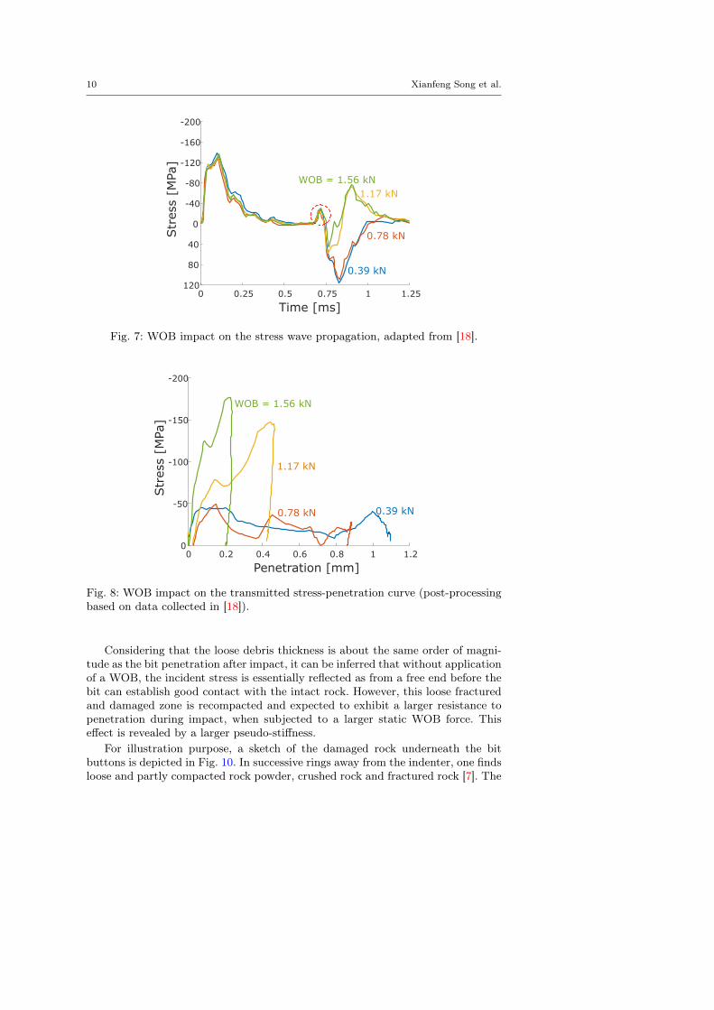
In percussive drilling tests conducted by Hustrulid [18] with an experimental set-up akin to a TH drill rig, the stress wave reflected from the BRI is observed todepend on the applied WOB levels. (The steel rod was designed to be long enoughto prevent the interference of incident and reflected stress wave measurement.) Atsmall WOB, the incident compressive stress wave essentially experiences a free-endreflection at the BRI, implying that virtually no energy is transmitted to the rock,refer to Fig. 7. As the WOB increases, the tensile portion of the wave becomessmaller while the compressive part becomes larger, which implies that the drillbit encounters more resistance at the BRI. Several more tests were implementedand superimposed to verify the repeatability of this observation [18]. It was foundthat the sequentially measured stress waves are identical given the same operatingconditions, which also confirms the adequacy of focusing on a single impact, asdone in this study.
In view of the nature of the set-up [18], the BRI of the F-P response can ac-tually be determined from longitudinal wave theory given the measured incidentand reflected stress wave, see Fig. 8. Our analysis of the experimental data in-dicates that the slopes of the F-P curves increase monotonically with the WOB,while the transmitted energy, which corresponds to the area under the F-P curve,increases with the WOB to reach a peak and then decreases. The presence of asmall compressive portion occurring at the beginning of the reflected stress wavein Fig. 7 (refer to the red circle highlighted region) is considered to be caused bythe increasing cross-sectional area at the bit front and not by the conditions atthe BRI [18]. Hence, this effect is ignored when constructing Fig. 8, especially asonly a slight difference is observed in a comparison of F-P curve with and withoutaccounting for this small compressive portion.
2.3.2 Influence of rock damage on the BRI pseudo-stiffness
Repeated drop tests reveal a significant nonlinear F-P response characterized byincreasing stiffness with penetration during the loading process, with the drillbit experiencing large displacement with relatively little resistance at the onsetof penetration [2, 18], see Fig. 9. This nonlinear response is understood to bemainly caused by the rock damage formed by previous impacts. The presence ofre-compacted fragments have a negative effect on the subsequent fragmentationprocess, although only a small amount of energy is absorbed by the re-compaction[50].
10 Xianfeng Song et al.
0 0.25 0.5 0.75 1 1.25
Time [ms]
120
80
40
0
-40
-80
-120
-160
-200
Str
ess
[MPa
]
1.17 kN
0.78 kN
0.39 kN
WOB = 1.56 kN
Fig. 7: WOB impact on the stress wave propagation, adapted from [18].
0 0.2 0.4 0.6 0.8 1 1.2
Penetration [mm]
0
-50
-100
-150
-200
Str
ess
[MPa
]
0.39 kN
WOB = 1.56 kN
0.78 kN
1.17 kN
Fig. 8: WOB impact on the transmitted stress-penetration curve (post-processingbased on data collected in [18]).
Considering that the loose debris thickness is about the same order of magni-tude as the bit penetration after impact, it can be inferred that without applicationof a WOB, the incident stress is essentially reflected as from a free end before thebit can establish good contact with the intact rock. However, this loose fracturedand damaged zone is recompacted and expected to exhibit a larger resistance topenetration during impact, when subjected to a larger static WOB force. Thiseffect is revealed by a larger pseudo-stiffness.
For illustration purpose, a sketch of the damaged rock underneath the bitbuttons is depicted in Fig. 10. In successive rings away from the indenter, one findsloose and partly compacted rock powder, crushed rock and fractured rock [7]. The

Influence of Weight-on-Bit on Percussive Drilling Performance 11
Fig. 9: Representative nonlinear force versus penetration curves obtained fromdrop tests for different impact energy and indexing angles, after [2].
BitDisintegrated/PartlyRecompacted Zone
Crushed Zone
Cracked Zone
Fig. 10: Sketch of cracks in rocks under indentation [7].
size of the crushed and the fractured zone mainly depends on the magnitude of theloading, the rock macro-mechanical properties, and the geometry of the indenter[7]. In addition, three systems of cracks: median cracks, radial cracks and sidecracks may exist outside the cracked zone.

12 Xianfeng Song et al.
2.4 Summary
The compiled experimental evidence leads to several remarkable results concerningthe characteristics of percussive drilling.
1. The BRI law is rate-independent in the range of impact velocity involved inpercussion drilling. It implies that the rate of penetration is proportional tothe product of the impact frequency and the energy dissipated in rock frag-mentation — essentially the energy transmitted to the rock — at each impact[51]. Since the percussion frequency varies little with the WOB and rock typegiven certain operating conditions, the transmitted energy per impact can beused as a proxy to the ROP to assess the influence of WOB.
2. The BRI law depends on the condition of the rock surface that is impactedby the bit. The presence of loose debris and subsurface damage lowers theapparent stiffness of the BRI, thus affecting the energy transmission and themaximum force that can be generated. The thickness of the damage zone isof the same order of magnitude as the bit displacement given a small WOB.This layer of damaged rock is known to respond non-linearly, with its normalstiffness increasing with the applied normal force.
3. The stiffness K of the interface increases with the WOB, as deduced froman analysis of the reflected stress wave in relation to the incident stress pulsegenerated by impact of the hammer. A relatively small WOB, however, is ableto compact the loose debris to a large extent prior to the arrival of the impulsiveload. Thus, the bit encounters higher resistance as penetration commencesunder a larger WOB.
In view of the experimental evidence that the BRI stiffness increases with theWOB and that any rate effects are negligible, it can be concluded that the influenceof the WOB on the ROP can be investigated by analyzing the dependence of theenergy transmitted to the rock as a function of the BRI pseudo-stiffness.
3 Force and Energy Transmitted to Rock at Each Impact
3.1 Conceptual Model
This extensive review of PD or DT experiments has led to the conclusion that thenon-monotonic ROP-WOB relationship likely reflects the non-monotonic variationof the transmitted energy with the BRI pseudo-stiffness K. On this basis, wedevelop a simple one-dimensional model to evaluate the effect of K — a functionof the WOB – on the stress wave/energy transmission efficiency of the percussivehammer system.
The model of the system consists of four collinear bodies, namely the hammer,the bit assembly in series with a spring representing the BRI and a dashpot toaccount for the intact rock, see the sketch in Fig. 11.
The hammer is treated here as a rigid massmh moving at velocity V0 at the mo-ment of impact [7]. Neglecting the wave propagation in the hammer is appropriatein view of the air-hammer geometry, which is usually designed to be a short cylin-der with large diameter to attain sufficient impact velocities over a short stroke[52]. The accuracy of the rigid hammer approximation has been demonstrated by

Influence of Weight-on-Bit on Percussive Drilling Performance 13
K,gK
m=1/l
HammerV0
Bit
Rock
Fig. 11: 1D indentation model for percussive drilling.
Wu [52], who showed that the simulated incident wave presents little deviationfrom the measurement. For illustration purpose, a perfect contact is assumed atthe hammer-bit interface (HBI) following the impact; the mismatch conditions dueto the interface roughness are thus neglected. The HBI stiffness influence on theenergy transmission efficiency has been investigated and demonstrated in [53].
The impact of the hammer on the bit at rest then induces stress waves prop-agating in the bit/BRI/rock system. The bit is regarded as an elastic cylinderwith Young’s modulus E. Since inertia effects in the rock being fractured is ofsmall significance [54], a weightless spring is introduced at the BRI interface torepresent the rock resistance to the bit penetration. Although a constant BRIloading pseudo-stiffness K is usually assumed in the literature, here motivated byexperimental evidence, K is understood to increase with the WOB in this con-ceptual model. Furthermore, as we are mainly concerned by the maximum energytransmission during the penetrating phase, the unloading phase is simplified byassuming an abrupt drop of the F-P response after peak penetration. In this case,the unloading slope, γK, is assumed to be infinitely large, i.e., γ →∞. This sim-plification should be adequate, since it is usually observed that most of the bitpenetration is irreversible as there is negligible recovery during unloading [55].
However, in the case of percussive drilling, reflection of incident wave occursdue to the discontinuity at the BRI. This discontinuity is partly attributed to thethird-body formed by previous impact as discussed above and also the impedancemismatch between the bit and intact rock. From a mathematical point of view,the homogeneous intact rock can be approximated by a dashpot to account forthe impedance contrast and the energy radiation effect.

14 Xianfeng Song et al.
V0mp
Hammer
Bit
E, r, A
(a) Prior impact
FiBit
(b) Step 1
Fi
Fr
K,gK
m=1/l
Bit
(c) Step 2
BitFr
(d) Step 3
Fig. 12: Process for one cycle of wave production, propagation and reflection
Finally, we assume that each impact is independent on account that the timeelapsed between two successive impacts is large enough [28, 33]. Indeed it is foundthat the dynamic stress in the bit assembly reduces to an insignificant level within0.01 sec after impact, which is smaller than the time interval (about 0.03 sec, equiv-alent to a 30Hz hammering frequency) between two impacts [41]. The repetitive-ness of the response to successive impact in percussive drilling tests, as indicatedby the virtually identical strain waves, confirms the independence of each impactloading [18].
This simple 1D model can thus be used to explore the key factors influencingthe energy and force transmission to the rock. It is motivated by the following con-siderations. First, the percussive drilling efficiency generally depends much moreon the mass of the bit than on its shape [3], and the load magnitude is reported tobe more important than its distribution across the face of the bit in the formationof subsurface fractures [7]. Second, the raw impact power delivered by the hammerto the bit-rock system remains essentially constant for a given input air pressure,despite the fact that WOB slightly changes the impact frequency [43]. The bitangular motion and the associated interaction among successive indentations arenot considered in this analysis. Finally, wave attenuation and dispersion is nottaken into account, considering that we only investigate the propagation of thefirst impulsive load. Hence the stress wave/energy is transmitted without any lossor distortion from the impacted end of the hammer to the BRI.
The stress perturbations can generally be interpreted as a sequence of threestages: (i) impact of the hammer on the bit, (ii) transmission of the stress wavethrough the BRI, and (iii) arrival of the reflected stress wave at the hammer/bitinterface (HBI), see Fig. 12. Since we are interested in evaluating the stress/energytransmission during the first impulsive loading process, the last stage is ignoredhere.
3.2 First Stage: impact between hammer-bit
The impact of the rigid hammer on the bit provokes a longitudinal compressiveforce wave Fi propagating at speed c towards the BRI, as illustrated in Fig. 12b.The propagation of the elastic disturbance in the bit assembly is governed by the

Influence of Weight-on-Bit on Percussive Drilling Performance 15
longitudinal wave equation∂2U
∂t2= c2
∂2U
∂x2(1)
where U = U(x, t) represents the displacement of a particle x along the elasticrod as a function of time t. The longitudinal wave velocity c =
√E/ρ, where E
is Young’s modulus and ρ is the density of the bit. d’Alembert’s general solutionresolves the wave equation by introducing a downward traveling wave Ui (travelingtoward the BRI) and an upward traveling wave Ur (traveling away from the BRI)
U(x, t) = Ui(ct− x) + Ur (ct+ x) (2)
Initially, the solution is simply given by U(x, t) = Ui(c1t−x) since there is no wavereflected from the BRI yet. The corresponding force F (x, t) and particle velocityV (x, t) distributed along the bit assembly is given by
F (x, t) = EA∂U
∂x= −EAU ′i (3)
V (x, t) =∂U
∂t= cU ′i (4)
where the prime denotes differentiation with respect to the argument of the func-tion, and compression is taken to be negative. Thus before any arrival of the backreflected wave at this point, the particle velocity at x is simply proportional to thelocal incident force V (x, t) = −F (x,t)c
EA .Provided the hammer impact on the drill bit is a momentum conservative
process, the motion of the striking hammer can be solved according to the rigidbody mechanics
mhV0 +
∫ t
0
F (0, τ)dτ = mhVh(t) (5)
with the origin of time taken to correspond to the moment of impact. In the above,F (0, t) is the compressive force acting at the interface between the hammer andthe bit, and Vh (t) represents the hammer velocity at t > 0. As a consequence ofassuming a rigid hammer and an ideal hammer-bit contact, there is an instanta-neous jump of the force at the HBI after the impact, followed by an exponentialdecay [56]
F (0, t) = −EAV0c
exp
(− EAmhc
t
)(6)
where A refers to the uniform cross-sectional area of the bit, see Appendix Afor details of the derivation. The impact force must be of a compressive nature,otherwise the two components are separated. In other words, the hammer cannotrebound but remain in contact with the bit, at least until the arrival of the wavereflected from the BRI.
In order to reduce the number of parameters in the expression, it is advan-tageous to reformulate the model in a dimensionless form by introducing scales.By nature, the percussive drilling process is characterized by multiple timescales[27]. Here in order to investigate the stress wave/energy transmission in one trans-mission cycle, the effective duration of the pulse generated by the impact of thehammer is selected as the time scale T∗; the hammer maximum movement follow-ing impact as the displacement scale U∗; the maximum impact force induced at

16 Xianfeng Song et al.
the HBI as the force scale F∗; and the hammer impact velocity as the velocityscale V∗. Thus,
T∗ =mhc
EAU∗ =
mhcV0EA
F∗ =EAV0c
V∗ = V0 (7)
Hence the dimensionless time τ , displacement u, force f , and dimensionless velocityv are defined as
τ =t
T∗u =
U
U∗f =
F
F∗v =
V
V∗
Therefore, prior to any reflected stress wave, the normalized force, displacementand velocity at the hammer-bit interface can be evaluated as
f(0, τ) = −e−τ , u(0, τ) = 1− e−τ , v(0, τ) = e−τ (8)
Attenuation or dispersion during the incident wave propagation is assumed tobe negligible before it reaches the BRI. Therefore, the non-dimensional incidentforce wave fi at the BRI is identical to f(0, τ), but for a fixed time delay.
3.3 Second Stage: interaction beween bit and rock
In the second stage, the incident force wave fi reaches the BRI, where it splitsbetween a reflected wave denoted as fr, and a transmitted wave ft, which is re-sponsible for the destructive work done on the rock, see Fig. 12c. The impactenergy is essentially partitioned into three components: dissipation on rock frag-mentation, elastodynamic radiation in the rock, and reflection to the hammer andthe drill bit [54]. However, the energy radiated by elastic wave is small comparedto the energy dissipated in rock fragmentation [54, 57, 58].
Numerous experiments have been conducted to characterize the F-P relation-ship at the BRI. The response of the interface consists of a loading phase at theend of which the bit reaches a maximum penetration. Indentation experimentsgenerally show little rebound after reaching the maximum penetration [54, 59],which implies that virtually all the energy transferred through the BRI is dissi-pated and radiated, and limited energy is recovered from the rock. Therefore, inthis study, we neglect the elastic recovery by assuming an abrupt drop of the forceat the interface upon unloading.
With the origin of time reset to the instant when the incident wave arrivesat the BRI, the incident wave at the BRI reads fi = −e−τ . As derived in theAppendix, the transmitted force ft during the loading process can be determinedfrom the BRI law.
dftdτ
+ κ (λ+ 1) ft = 2κfi, 0 ≤ τ ≤ τp (9)
where τp corresponds to the time instant when the loading process terminates.Accordingly, the transmitted force ft in the loading phase is given by
ft = 2κe−τ(κ+κλ) − e−τ
κ+ κλ− 1(10)

Influence of Weight-on-Bit on Percussive Drilling Performance 17
max
Fig. 13: Maximum transmitted force as a function of impedance ratio λ and BRIpseudo-stiffness κ.
Two numbers, κ and λ are introduced in the above equation: the scaled BRIpseudo-stiffness κ and the bit/rock impedance ratio λ
κ :=Kmhc
2
(EA)2λ :=
AE/c
ArEr/cr. (11)
The peak force ftmax transmitted at the BRI is reached at time τp when thepenetration rate vanishes
τp =ln(κ+ κλ)
κ+ κλ− 1
and ftmax thus reads
ftmax =2κ
κ+ κλ− 1
((κ+ κλ)−
κ+κλκ+κλ−1 − (κ+ κλ)−
1κ+κλ−1
)(12)
The dependence of the maximum force ftmax on the BRI pseudo-stiffness κand on the impedance ratio λ is illustrated in Fig. 13. This figure shows thatftmax increases asymptotically with κ but decreases with λ. This latter trend isin agreement with experimental observations that the maximum transmitted forceincreases as the rock becomes stiffer [54]. The maximum force ftmax ultimatelysaturates around 2 as λ → 0, κ → ∞, which is analogous to a reflection from afixed boundary. At this limit, the force transmitted at the BRI is twice the incidentforce.
A portion of the incident stress wave is reflected from the BRI and travelsbackward to the hammer-bit interface. The reflected force, denoted as fr, is givenby
fr =2κe−τ(κ+κλ)
κ+ κλ− 1+ e−τ − 2κe−τ
κ+ κλ− 1(13)

18 Xianfeng Song et al.
In general, the reflected stress wave consists of an initial tensile portion following bya compressive tail. The impact loading phase prevails as long as the bit penetrationproceeds. Once the maximum penetration has been reached, the unloading phaseoccurs along the idealized vertical F-P curve. Hence, the transmitted force duringthe unloading phase is determined as:
ft =2fi1 + λ
Accordingly, the work wt expended by the transmitted force ft on the rock is
wt =
∫ τi
0
ftvbdτ (14)
where τi is the incident impulse length which determines the duration for the wavetransmission, and vb is the bit bottom-end velocity given by vb = fr − fi. Notethat the work done by the static WOB during penetration of the bit is very smallcompared to the energy dissipated on rock fragmentation [43, 44], and is thereforeneglected.
3.4 Efficiency
Both the experimental evidence and the numerical simulations summarized in thenext Section suggest that the impedance ratio λ is small. Therefore, the conditionλ = 0 is a useful limiting case to investigate the conditions leading to the maximumenergy transfer in percussive drilling. Let η (= 2wt) denote the proportion of theimpact energy that is transmitted to the rock during the first wave propagationcycle (in the absence of multiple reflections). In the limiting case, λ = 0, whichimplies a rigid rock foundation, and γ →∞, the energy transmission efficiency isgiven by
η =4κ
(κ− 1)2
(κ1/1−κ − κκ/1−κ
)2(15)
The dependence of η on κ is plotted in Fig. 14. The plot of η (κ) indicates thatη → 0 in the two limits when either κ → 0 or κ → ∞ and that the transmissionefficiency is maximum at κ = 1 with ηmax = 4e−2 ' 0.54.
No energy is transmitted to the rock by the incident wave if the BRI pseudo-stiffness κ = 0, which reflects a situation where the BRI offers negligible resistanceto the bit advance. The small κ regime is in agreement with Hustrulid’s observa-tion [18] that the incident stress wave was reflected as from a free end under asmall WOB and the net work (corresponding to the area under the F-P curve) isapproximately zero. Moreover, if the BRI pseudo-stiffness κ → ∞, λ = 0, whichessentially represents fixed end condition, no energy will be transferred to the rockeither, since no displacement is produced at BRI. Therefore, there must exist anoptimal condition for the energy transfer from the bit to the rock (interpreted asthe ROP) in terms of the BRI pseudo-stiffness (which is monotonically dependenton the WOB).
The more general conditions when the impedance ratio is non-zero is illus-trated in Fig. 15. This figure, which plots the variation of the energy transmissionefficiency with both κ and λ, shows that there is an optimal BRI stiffness, function

Influence of Weight-on-Bit on Percussive Drilling Performance 19
Fig. 14: Variation of energy transmission efficiency η with BRI stiffness κ. Themaximum efficiency, 4e−2, corresponds to κ = 1 for λ = 0.
Fig. 15: Energy transmission efficiency in terms of pseudo-stiffness κ andimpedance ratio λ.
of impedance ratio, that maximizes the energy delivered from the bit to the rock,provided that λ is small enough. For λ larger than the estimated critical valueλ∗=0.3, the existence of an optimum κ disappears. In particular, the transmissionefficiency η increases asymptotically with κ from 0 to 1 when λ = 1 suggestingthat all the impact energy can theoretically be transferred through the BRI pro-vided a good contact and the same impedance between the bit and intact rock.The incident wave and impact energy are fully reflected in the limit of an infiniteimpedance ratio.

20 Xianfeng Song et al.
In summary, the 1D phenomenological model shows that the BRI pseudo-stiffness κ and the bit-rock impedance ratio λ are the two critical numbers de-termining the drilling performance. There exists an optimal stiffness κ, whichmaximizes the energy transmitted from the bit to the rock, provided that theimpedance ratio is small enough.
4 Discussion
According to the 1D phenomenological model described in this paper, the existenceof a sweet spot hinges on the smallness of the impedance ratio. We demonstratethe plausibility of a small λ in percussion drilling by interpreting experimentaldata and also by estimating λ from numerical simulations conducted with anaxisymmetric finite element model. Calculations performed for various values ofthe interface stiffness also confirm the existence of a sweet spot.
4.1 Estimate of impedance ratio from test data
A set of data from a published laboratory percussion drilling experiment [52]provides an opportunity to estimate the actual impedance ratio λ. In this particularexperiment, the incident force wave essentially experiences a fixed-end reflection,as the amplitude of reflection is approximately the same as the incident wave andthe tensile portion is almost negligible [54]. Such a signature is only possible if κ issufficiently large (so that the BRI is effectively characterized only by an impedancecontrast) and λ is small. According to longitudinal wave considerations about thetransmission and reflection of an incident wave across a material discontinuity, λcan be assessed from
λ =fi − frfi + fr
(16)
Alternatively, Eq. (16) can be deduced from Eq. (9) by noting that bounded termdftdτ disappears for large κ. However, the mean value of λ is better estimated from
τp∫0
λ2dτ =
τp∫0
f2i + f2
r − 2fifrf2i + f2
r + 2fifrdτ
where the duration of loading phase τp is estimated from the drilling data. For theexperiments reported by [52], the average λ is estimated to be 0.13.
There is also indirect evidence that more impact energy is absorbed by lesscompetent rock in percussive drilling tests [54]. Interpreting these observationswithin the framework of the model, these observations indicate that the energytransmission efficiency increases with λ, which is inversely proportional to the rockelastic modulus according to Eq. (11). However, such a trend is only possible if λis small, as can be seen in Fig. 16, where the range of λ is restricted to a smallrange. In this range of λ, an optimal pseudo-stiffness likely exists for maximizingthe energy transmission.

Influence of Weight-on-Bit on Percussive Drilling Performance 21
Fig. 16: Energy transmission effficiency plot in terms of pseudo-stiffness andimpedance ratio, from a different angle.
4.2 Estimate of Impedance Ratio from Simulation
The impedance ratio λ can also be estimated from numerical simulations with therock mass represented by a 3D elastic continuum. Here we report the results ofnumerical simulations showing that the impedance ratio is small (see Fig. 17).
The axisymmetric model used for the simulations is developed in COMSOLMulti-physics. For simplicity, the bit assembly is modeled as a cylinder, and all thebit buttons are replaced by an equivalent rigid button. The inertial effect of thethird body is neglected by assuming its density to be zero. In addition, the Poissonratio for the third body and the drill bit is assumed to be zero to mimic the springresistance effect and wave propagation in a bar as in the one-dimensional model.Besides, in order to conveniently characterize the effect of the impedance ratio onimpact transmission, the BRI pseudo-stiffness influence on the stress wave/energytransmission is eliminated by assuming a large Young’s modulus of the third-body.Finally, the non-reflective boundary condition is imposed at the lower and outerboundary of the rock to mimic the semi-infinite nature of the rock mass.
A high quality mesh consisting of triangular and quadrilateral elements wasgenerated by applying COMSOL default mesh function "free triangular" and"mapped mesh" on the rock and on the bit domain, respectively. A high resolutionmesh is defined in the vicinity of the BRI to accurately capture the penetration andforce transmission. The rock was discretized with 3002 elements, the third bodywith 40, and the drill bit assembly with 4656. A pre-defined incident force wave wasapplied on the upper bound of the drill bit assembly: Fi = (F∗t/T∗) exp (−t/T∗),where T∗ = 2 ·10−5[s] and F∗ = 2 ·105 [N]. The total simulation time was 8 ·10−4 s,with the integration time step set to 10−8. The material properties and geometrydetails are given in Table 1.

22 Xianfeng Song et al.
Components E (GPa) ν ρ (kg/m3) Dimensions (cm)
Bit 200 0 7800 H: 199, W: 2Button 890 0.07 3510 H: 1, W: 0.6Third Body 1000 0 0 H: 1, W: 3Rock 60 0.2 2707 H: 299, W: ∼100
Table 1: Parameters used in the FE analysis: Young’s modulus E, Poisson’s ratioν, density ρ, and dimensions of height H and width W .
No
Ref
lect
ion
ButtonThird Body
Bit
Rock
No Reflection
Free
Fig. 17: Geometry built in the FEA analysis.
The impedance ratio λ was directly calculated from
λ = −vbft
(17)
where the velocity vb of the button bottom and the transmitted force ft can beextracted directly during the simulation. It is estimated the average impedanceratio in this numerical model is less than 0.1.
4.3 Simulation of Sweet Spot
The influence of the BRI pseudo-stiffness on the stress wave/energy transmissionwas investigated with the FE model by conducting a parametric study of the third-body stiffness, see Fig. 17. The simulations confirm that that an optimal pseudo-stiffness exists for maximizing the energy transmission, see Fig. 18. This optimalconfiguration appears regardless of the yield criterion, either Drucker-Prager orHoek-Brown, to simulate failure of the rock under the button.

Influence of Weight-on-Bit on Percussive Drilling Performance 23
Fig. 18: Variation of the energy transmission efficiency η with the BRI pseudo-stiffness, as computed with the FE model.
5 Conclusions
The phenomenological model for percussion drilling described in this paper pre-dicts a non-monotonic dependence of the transferred energy on the BRI pseudo-stiffness and thus the existence of an optimum WOB that maximizes the ROP –the so-called sweet spot. According to this model, the root cause behind the sweetspot is the dependence of the BRI pseudo-stiffness on the WOB. This explana-tion contrasts with the various reasons advanced in the literature, which includeincreasing wear of the bit, reduced indexing, and poor cleaning of the debris. Areview of the published experimental data has uncovered evidence that the ROPis directly related to energy transmitted to the rock at each impact, and thatthe BRI pseudo-stiffness increases with the WOB. Moreover, a simple 1D modelshows that there is an optimal BRI pseudo-stiffness that maximizes energy trans-mission to the rock during the first impulsive wave, provided that the bit/rockimpedance ratio is small. With further enhancements, this model can form thebasis for a model-based parameter identification and ROP optimization controlalgorithm running in real-time alongside the drilling operation.
Acknowledgement
This study is a part of the research project INNO-Drill (Technology platformfor research-based innovations in deep geothermal drilling) funded by The Re-search Council of Norway (grant 254984) and industry partners (Epiroc, EnelGreen Power, Lyng Drilling, NOV, Ravel, Robit, Rock Energy, Sandvik Miningand Construction, Tomax and Zaptec).

24 Xianfeng Song et al.
References
1. R. Ghosh, H. Schunnesson, A. Gustafson, Monitoring of Drill System Behaviorfor Water-Powered In-The-Hole (ITH) Drilling, Minerals 7(7), 121 (2017). DOI10.3390/min7070121
2. M. Fourmeau, A. Depouhon, A. Kane, H. Hoang, E. Detournay, Influence ofindexation and impact energy on bit/rock interface law in percussive drilling:An experimental study, in 49th U.S. Rock Mechanics/Geomechanics Sympo-sium (American Rock Mechanics Association, San Francisco, California, 2015)
3. B. Lundberg, Microcomputer simulation of stress wave energy transfer to rockin percussive drilling, International Journal of Rock Mechanics and MiningSciences & Geomechanics Abstracts 19(5), 229 (1982). DOI https://doi.org/10.1016/0148-9062(82)90221-2
4. L.F.P. Franca, A bit–rock interaction model for rotary–percussive drilling, In-ternational Journal of Rock Mechanics and Mining Sciences 48(5), 827 (2011).DOI 10.1016/j.ijrmms.2011.05.007
5. G. Han, M.B. Dusseault, E. Detournay, B.J. Thomson, K. Zacny, Principles ofDrilling and Excavation (John Wiley & Sons, Ltd, 2009), chap. 2, pp. 31–140.DOI 10.1002/9783527626625.ch2
6. M.S. Bruno, Fundamental Research on Percussion Drilling : Improved rockmechanics analysis , advanced simulation technology , and full- scale labora-tory investigations. Tech. Rep. 626, Terralog Technologies Inc (2005)
7. S. Kou, Some Basic Problems in Rock Breakage by Blasting and by Indenta-tion. Ph.D. thesis, Tekniska Högskolan i Luleå (1995)
8. H.L. Hartman, The Effectiveness of Indexing in Percussion and RotaryDrilling, International Journal of Rock Mechanics & Mining Sciences 3, 265(1966)
9. A. Muhammad, Control of ith percussive long hole drilling in hard rock. Ph.D.thesis, McGill University (1996)
10. G. Han, M. Bruno, K. Lao, Percussion Drilling in Oil Industry : Review andRock Failure Modelling, in AADE 2005 National Technical Conference andExhibition (Houston, Texas, 2005)
11. S. Kivade, C.S. Murthy, H. Vardhan, Experimental Investigations on Penetra-tion Rate of Percussive Drill, Procedia Earth and Planetary Science 11, 89(2015). DOI 10.1016/j.proeps.2015.06.012
12. H.F. Unger, R.R. Fumanti, Percussive drilling with independent rotation, U.S.Dept. of Interior, Bureau of Mines (1972)
13. E. Cheetham, WR and Inett, Factors affecting the performance of percussivedrills, Transactions of the Institution of Mining and Metallurgical Engineers63, 45 (1953)
14. W.A. Hustrulid, C. Fairhurst, A theoretical and experimental study of thepercussive drilling of rock Part IV-application of the model to actual percus-sion drilling, International Journal of Rock Mechanics and Mining Sciences& Geomechanics Abstracts 9(3), 431 (1972). DOI https://doi.org/10.1016/0148-9062(72)90007-1
15. A. Depouhon, Integrated dynamical models of down-the-hole percussivedrilling. Ph.D. thesis, Université de Liège, Liège, Belgique (2014)
16. R.G. Lundquist, Rock drilling characteristics of hemispherical insert bits. Mas-ter’s thesis, University of Minnesota (1968)

Influence of Weight-on-Bit on Percussive Drilling Performance 25
17. E. Nordlund, The effect of thrust on the performance of percussive rock drills,International Journal of Rock Mechanics and Mining Sciences & Geomechan-ics Abstracts 26(1), 51 (1989). DOI https://doi.org/10.1016/0148-9062(89)90525-1
18. W.A. Hustrulid, A study of energy transfer to rock and prediction of drillingrates in percussive drilling. Master’s thesis, University of Minnesota (1965)
19. W. C. Maurer, The "Perfect - Cleaning" Theory of Rotary Drilling, Journalof Petroleum Technology 14, 1270 (1962). DOI 10.2118/408-PA
20. G. Pearse, Hydraulic Rock Drills, Minning Magzines pp. 220–231 (1985)21. S. Shaw, Effects of Farying Degrees of Rotation on Rate of Penetration of
Percussion Drill Bits, Unpublished Report (1965)22. H. Schunnesson, Drill Process Monitoring in Percussive Drilling-A Multivari-
ate Approach To Data Analysis. Ph.D. thesis, Luleå University of Technology(1990)
23. A.M. Krivtsov, M. Wiercigroch, Penetration rate prediction for percussivedrilling via dry friction model, Chaos, Solitons & Fractals 11(15), 2479 (2000)
24. E. Pavlovskaia, M. Wiercigroch, C. Grebogi, Modeling of an impact systemwith a drift, Physical Review E 64(5), 056224 (2001)
25. O.K. Ajibose, M. Wiercigroch, E. Pavlovskaia, A.R. Akisanya, Global and localdynamics of drifting oscillator for different contact force models, InternationalJournal of Non-Linear Mechanics 45(9), 850 (2010)
26. O.K. Ajibose, M. Wiercigroch, E. Pavlovskaia, A.R. Akisanya, G. Károlyi,Drifting impact oscillator with a new model of the progression phase, Journalof applied mechanics 79(6) (2012)
27. A. Depouhon, V. Denoël, E. Detournay, Numerical simulation of percussivedrilling, International Journal for Numerical and Analytical Methods in Ge-omechanics 39(8), 889 (2015). DOI 10.1002/nag.2344
28. B. Lundberg, Energy transfer in percussive rock destruction-I: Comparisonof percussive methods, International Journal of Rock Mechanics and Min-ing Sciences & Geomechanics Abstracts 10(5), 381 (1973). DOI 10.1016/0148-9062(73)90024-7
29. B. Lundberg, Microcomputer simulation of percussive drilling, InternationalJournal of Rock Mechanics and Mining Sciences & Geomechanics Abstracts22(4), 237 (1985). DOI 10.1016/0148-9062(85)92951-1
30. B. Lundberg, M. Okrouhlik, Influence of 3D effects on the efficiency of per-cussive rock drilling, International Journal of Impact Engineering 25(4), 345(2001). DOI 10.1016/S0734-743X(00)00053-1
31. B. Haimson, High velocity, low velocity and static bit penetration character-istics in Tennessee Marble. Master’s thesis, University of Minnesota (1966)
32. J. Paone, D. Madson, W.E. Bruce, U. States., B. of Mines., Drillability studies-laboratory percussive drilling (U.S. Dept. of the Interior, Bureau of Mines,[Washington, D.C.], 1969)
33. C. W. Berry, Effect of Varying Bit Shape on Force-Penetration Characteristicsin Rock for Impulsive Loading. Master’s thesis, University of Minnesota (1959)
34. H.L. Hartman, Basic studies of percussion drilling, Mining Engineering 11, 68(1959)
35. C. W. Maurer, Impact crater formation in sandstone and granite. Master’sthesis, Colorado School of Mines (1959)

26 Xianfeng Song et al.
36. P.F. Gnirk, An experimental investigation of the indexing phenomenon forstatic single-tooth penetration in Indiana limestone, University of MinnesotaSchool of Mines and Metallurgy (1962)
37. H. Hartman, Crater geometry relations in percussive drilling, Mine and QuarryEngineering (1962)
38. B.R. Stephenson, Measurement of Dynamic Force-Penetration Characteristicsin Indiana Limestone. Master’s thesis, University of Minnesota (1963)
39. R. Simon, Transfer of the stress wave energy in the drill steel of a percussivedrill to the rock, International Journal of Rock Mechanics and Mining Sci-ences & Geomechanics Abstracts 1(3), 397 (1964). DOI 10.1016/0148-9062(64)90006-3
40. X. Song, P.A. Kane, O.M. Aamo, E. Detournay, A time scale regard on percus-sion drilling, International Journal of Impact Engineering (2020). Submitted,June 2020
41. G. Han, M. Bruno, Lab investigations of percussion drilling from single im-pact to full scale fluid hammer, in 41st US Rock Mechanics/GeomechanicsSymposium (American Rock Mechanics Association, Golden, Colorado, 2006)
42. W.A. Hustrulid, C. Fairhurst, A theoretical and experimental study of thepercussive drilling of rock part III-experimental verification of the mathemat-ical theory, International Journal of Rock Mechanics and Mining Sciences and9(3), 417 (1972). DOI 10.1016/0148-9062(72)90006-X
43. L.E. Izquierdo, L.E. Chiang, A methodology for estimation of the specificrock energy index using corrected down-the-hole drill monitoring data, MiningTechnology 113(4), 225 (2004). DOI 10.1179/037178404225006218
44. D. Zou, Rock Drilling, in Theory and Technology of Rock Excavation forCivil Engineering (Springer, Singapore, 2017), pp. 49–103. DOI 10.1007/978-981-10-1989-0
45. W.A. Hustrulid, Theoretical and experimental study of percussive drilling ofrock. Ph.D. thesis, University of Minnesota (1968)
46. B.W. Vanzant, Dynamic rock penetration tests at atmospheric pressure, in5th Symposium on rock Mechanics (University of Minnesota, 1962)
47. R. Worsley, Energy, impulse, and velocity effects in fracturing produced bychisel bits in limestone. Ph.D. thesis, Colorado School of Mines (1960)
48. C. Fairhurst, Wave Mechanics of Percussive Drilling, Mine and Quarry Engi-neering pp. 122–130 (1961)
49. C.D. Haynes, Constant energy-variable velocity effects in percussive drilling.Ph.D. thesis, Pennsylvania State University (1963)
50. P.A. Lindqvist, L. Hai-hui, Behaviour of the Crushed Zone in Rock Indenta-tion, Rock Mechanics and Rock Engineering 207, 199 (1983)
51. Howard L. Hartman, Drilling Principles, in Surface Mining, 2nd Edition, ed.by B.A. Kennedy, B. A. Kennedy (Society for Mining, Metallurgy, and Explo-ration, 1990), chap. Mining Ope, pp. 513–523
52. C. Wu, Influence of Springy Impact Interface and Curved Drill Rods on En-ergy Transfer in Percussive Rock Drilling. Ph.D. thesis, Luleå University ofTechnology (1993)
53. C. Wu, An analytical study of percussive energy transfer in hydraulic rockdrills, Mining Science and Technology 13(1), 57 (1991). DOI 10.1016/0167-9031(91)90254-A

Influence of Weight-on-Bit on Percussive Drilling Performance 27
54. L.E. Chiang, D.A. Elías, Modeling impact in down-the-hole rock drilling, In-ternational Journal of Rock Mechanics and Mining Sciences 37(4), 599 (2000).DOI 10.1016/S1365-1609(99)00124-0
55. B. Lundberg, P. Collet, Optimal wave with respect to efficiency in percussivedrilling with integral drill steel, International Journal of Impact Engineering37(8), 901 (2010). DOI 10.1016/J.IJIMPENG.2010.02.001
56. K.F. Graff, Wave Motion in Elastic Solids. Dover Books on Physics Series(Dover Publications, 1975)
57. R. Simon, Energy Balance in Rock Drilling, in Texas Drilling and RockMechamcs Symposium (Society of Petroleum Engineers, 1963). DOI 10.2118/499-PA
58. B. Lundberg, M. Okrouhlik, Efficiency of a percussive rock drilling processwith consideration of wave energy radiation into the rock, International Jour-nal of Impact Engineering 32(10), 1573 (2006). DOI 10.1016/J.IJIMPENG.2005.02.001
59. W.A. Hustrulid, C. Fairhurst, A theoretical and experimental study of thepercussive drilling of rock Part II-force-penetration and specific energy de-terminations, International Journal of Rock Mechanics and Mining Sciences& Geomechanics Abstracts 8(4), 335 (1971). DOI https://doi.org/10.1016/0148-9062(71)90046-5
A Appendix
A.1 Hammer-Bit Interface
The equation governing the evolution of the displacement of the HBI following impact isformulated by substituting into Eq. (5), the following expressions for the velocity and force atthe HBI
Vh(t) =∂U
∂t|x=0 = cU ′(ct) (18)
F (0, t) = EA∂U
∂x|x=0 = −EAU ′(ct) (19)
which are obtained by setting x = 0 in Eqs. (3) and (4). Thus∫ t
0U ′(cτ)dτ = −
mh
EA
(cU ′(ct)− V0
)(20)
After integrating the left term, this equation becomes
U ′(ct) +EA
mhc2U(ct) =
EA
mhc2U(0) +
V0
c(21)
whose general solution is
U(ct) = De− EAmhc
t+ U(0) +
mhc
EAV0 (22)
After identifying the constant D using the initial condition U(0) = 0, the displacement of theHBI induced by the impact of the rigid hammer is is given by
U(ct) =mhcV0
EA
[1− e−
EAmhc
t]
(23)
The displacement increases from t = 0 to asympotically reach mhcV0EA
at large time providedthat the elastic bit assembly is unbounded.

28 Xianfeng Song et al.
A.2 Bit-Rock Interface
Once the incident wave reaches the BRI, the force balance at the interface is given by
ft = κ(u2 − u1), 0 ≤ τ ≤ τp (24)
where u1 and u2 represent the displacement at the BRI on the bit and rock side, respectively.Differentiating Eq. (24) with respect to time yields
dft
dτ= κ(v2 − v1), 0 ≤ τ ≤ τp (25)
Given the assumed semi-infinite and homogeneous nature of the rock, no wave reflection in therock will occur. Hence, the velocity v1 and v2 on both sides of the interface can be expressedas {
v1 = ft − 2fiv2 = −λft
, 0 ≤ τ ≤ τp (26)
Substituting Eq. (26) back into Eq. (25) yields the equation governing the evolution of theforce applied by the bit on the rock
dft
dτ+ κ (λ+ 1) ft = 2κfi, 0 ≤ τ ≤ τp (27)