fatigue of 8630 cast steel in the presence of shrinkage porosity
Upload
hoanghuongCategory
view
216download
0
International Journal of Fatigue 25 (2003) 245–256www.elsevier.com/locate/ijfatigue
Influence of porosity on the fatigue limit of die cast magnesiumand aluminium alloys
H. Mayera,∗, M. Papakyriacoua, B. Zettl a, S.E. Stanzl-Tschegga
a Institute of Meteorology and Physics, University of Agricultural Sciences, Turkenschanzstr. 18, A-1180 Vienna, Austria
Received 9 January 2002; received in revised form 1 May 2002; accepted 3 May 2002
Abstract
High cycle fatigue properties of high-pressure die-cast magnesium alloys AZ91 hp, AM60 hp, AE42 hp, AS21 hp and of similarlyproduced cast aluminium alloy AlSi9Cu3 have been investigated. Ultrasonic fatigue tests up to 109 cycles show mean fatigue limitsof approx. 38–50 MPa (magnesium alloys) and 75 MPa (AlSi9Cu3) in the tested casting condition. Fatigue cracks initiated atporosity in 98.5% of the samples. Considering porosity as initial cracks, specimens fail, if critical stress intensity amplitude,Kcr isexceeded.Kcr of the magnesium alloys range from 0.85±0.05 to 1.05±0.05 MPa√m, and 1.85±0.10 MPa√m was found for AlSi9Cu3.Below Kcr, fatigue cracks may initiate at porosity, however, do not propagate until failure. UsingKcr, the statistical distribution ofdefects is linked to the fracture probability at different stress amplitudes. 2002 Elsevier Science Ltd. All rights reserved.
Keywords: Cast magnesium; Cast aluminium; Porosity; High-cycle fatigue; Fatigue limit
1. Introduction
Cast magnesium alloys have recently receivedincreased attention as possible structural materialsbecause of their low density and their rather highstrength-to-weight ratio. Automotive applications areone of the possibilities where the benefits of weightreduction and, consequently, fuel saving is important[1,2]. Today, magnesium alloys are used in cars for lowstress applications such as covers (e.g. camshaft covers,clutch housings, valve covers) and less frequently formechanically loaded structural components such aswheels, transmission housings and pedals. Fatigueproperties of materials used for stressed componentshave to be known, since cyclic loading rather than staticloads may cause failure. The number of load cycles inautomotive applications may be relatively high, i.e. carwheels are stressed at variable amplitude with several108 cycles in service, and the high cycle fatigue proper-ties are therefore of great interest. A compilation of S-N
∗ Corresponding author: Tel.:+43-1-4705820-10; fax:+43-1-4705820-60.
E-mail address: [email protected] (H. Mayer).
0142-1123/03/$ - see front matter 2002 Elsevier Science Ltd. All rights reserved.doi:10.1016/S0142-1123(02)00054-3
data of different cast magnesium alloys [3] shows fatiguelimits of some alloys (on basis of 108 cycles) may exceed80 MPa, which is in the range of several cast aluminiumalloys, for example. However, the fatigue data of speci-ally cast and heat-treated samples may not be typicalfor the quality obtained in cast components. Rather it isnecessary to use the fatigue properties of magnesiumalloys that are cast under conditions similar to the cast-ing conditions for actual components. Several materialdefects, including porosity, oxide films or intermetallicinclusions [4] may facilitate fatigue crack initiation,reduce lifetimes and decrease the cyclic strength,especially at high numbers of cycles.
The present work addresses the high cycle fatigueproperties of aluminium-containing magnesium alloysproduced by high-pressure die-casting and their perform-ance in comparison to similarly produced cast aluminiumalloys. A main material defect in high-pressure die-castcomponents is porosity, which is caused by microshrink-age and by dissolved gases leading to voids. In cast alu-minium alloys, the influence of porosity on fatiguebehaviour has been addressed by several researchers [5–12] because of the prominent role of this kind of defect.High cycle fatigue investigations of aluminium cast alloy356 showed that fatigue cracks predominately initiate at

246 H. Mayer et al. / International Journal of Fatigue 25 (2003) 245–256
voids, if their mean diameters are greater than approx.50–100 µm [13–15]. This means that voids have to beconsidered as a main source of fatigue cracks for compo-nents produced by common casting techniques, such assand casting or die-casting.
Lifetimes measured for materials containing porosityare typically subjected to increased scatter, since the cyc-lic properties of specimens depend on the sizes of event-ual porosity and their location in the stressed volume,i.e. in the interior or at the surface. Several investigationsof cast aluminium alloys show a distinct correlation ofthe size of porosity at crack initiation and the numberof cycles to failure at constant load amplitude [5–7,12]as well as under variable amplitude loading conditions[9,11]. It has been generally assumed, that the stress con-centration at pores or similar defects causes early crackinitiation and that lifetime is essentially determined bythe numbers of cycles necessary to propagate the crackuntil rupture. Recent investigations have confirmed thishypothesis and showed, that crack initiation life is negli-gible compared to cycles to failure, i.e. cracks are visiblebelow 105 cycles although the specimen is cycled belowthe fatigue limit and did not fail during the next 108
cycles [12]. Models used to predict lifetimes of porouscast aluminium alloys determine the cycles necessary topropagate a crack from the initial defect size to fracture.Couper et al. [5] used linear elastic fracture mechanicprinciples, i.e. assuming a power law dependence ofeffective stress intensity range and crack propagationrate. Considering the effective threshold stress intensityand the stress concentration at porosity [6] as well asincreased growth rates of short cracks [7,11] served toincrease the accuracy of the calculations. Caton et al.[16] showed, however, that growth rates of small fatiguecracks in cast aluminium are not uniquely related to theeffective cyclic stress intensity. Depending on stressamplitude and microstructure, short cracks may grow atlower or higher growth rates than assumed using theeffective stress intensity range. Using a crack propa-gation law obtained from short crack growth studies,lifetimes of aluminium alloy 319 could be predicted withgood accuracy [12].
Fatigue investigations of cast aluminium alloysmainly concentrate on the regime below approx. 107-108
cycles to failure. Recent investigations in the very highcycle regime show that fatigue properties at 109 cyclescannot be accurately predicted and lifetimes may beunderestimated as well as overestimated when extrapol-ating from fatigue data obtained below 107 or 108 cycles[17]. Although some models of porous cast aluminiumalloys assume a fatigue limit [5–7] experimental verifi-cation of this hypothesis above 108 cycles is limited [12].Such investigations are necessary, since gravity die-castaluminium cast alloy 356, for example, may [18] or maynot [14] show a fatigue limit above approx. 108 cycles,depending on the actual amount of porosity.
Compared to cast aluminium alloys, studies of thefatigue properties of cast magnesium alloys are morelimited [19–24]. Several investigations, however, showthe prominent role of porosity acting as preferentialcrack initiation places [20–23]. Similar to cast alu-minium, the number of cycles to failure for a given stresslevel can be correlated to the size of the porous area atthe crack initiation place, i.e. the larger the defect areathe lower the fatigue lifetime at a certain stress amplitude[14]. The deleterious influence of defects is especiallypronounced at low cyclic stresses, where specimens con-taining large porosity may fail after 106 cycles, whereasothers survive more than 109 cycles [21].
The present study examines the high and very highcycle fatigue properties of cast magnesium alloys AZ91hp, AM60 hp, AE42 hp and AS21 hp and cast alu-minium alloy AlSi9Cu3. All materials were producedsimilarly by high-pressure die-casting. The data shownwill include 8 to 14 specimens of each material loadedwith 109 cycles or more, which allows a determinationof whether or not these alloys show a fatigue limit withinthis range. Testing several samples at very high numbersof cycles is possible using ultrasonic fatigue testingequipment working at a cycling frequency of 20 000 Hz[25]. With regards to apprehensions considering eventualfrequency influences on cyclic properties, the results arecompared to fatigue data measured with conventionalequipment at 50 Hz [26]. Fracture surface investigationsof specimens, which failed below 109 cycles, are evalu-ated and compared to runnouts, which were fracturedafterwards at somewhat higher stress amplitudes.Assuming porosity as initial cracks, linear elastic frac-ture mechanics principles serve to establish a correlationbetween defect size and fatigue limit. This allows a com-bination of the statistical probability of different porositysize with the probability of failure at different stress lev-els.
2. Materials and procedure
2.1. Materials
Fatigue experiments have been performed with fourmagnesium alloys (AZ91 hp, AM60 hp, AE42 hp andAS21 hp) and one aluminium alloy (AlSi9Cu3) pro-duced by high-pressure die-casting. To investigate theinfluence of porosity on fatigue lifetime, additional testshave been performed with AZ91 hp produced by Vacuraldie-casting, which leads to low porosity. Chemical com-positions of the investigated alloys are shown in Table1, and static strength properties and Vickers hardness(HV) are summarised in Table 2 [26]. HV have beenmeasured with indentation force 613 N (62.5 kp) evalu-ating 10 indentations in each material.
Cast sheets with stepwise varying thickness were pro-

247H. Mayer et al. / International Journal of Fatigue 25 (2003) 245–256
Table 1Chemical compositions (in wt%) of the investigated materials
Al Zn Mn Si Ce Fe Cu Ni Mg
AZ91 hp 8.90 0.79 0.21 0.01 0.003 0.001 0.001 remAM60 hp 6.10 0.01 0.29 0.01 0.003 0.002 0.001 remAE42 hp 3.90 0.004 0.37 0.007 0.94 0.0003 0.0003 0.001 remAS21 hp 2.20 �0.01 0.16 0.98 �0.01 �0.002 �0.001 remAlSi9Cu3 rem 1.2 0.1-0.4 8-11 1.0 2.0-3.5 0.1-0.5
Table 2Ultimate tensile strength (Rm), yield stress (Rp0.2), fracture strain (A5)[26] and Vickers hardness
Rm (MPa) Rp0.2 (MPa) A5 (%) Vickers hardness[HV]
AZ91 hp 190 118 3.6 65±2AM60 hp 178 86 5.3 47±1.5AE42 hp 184 101 5.0 57±2AS21 hp 131 84 2.1 55±2AlSi9Cu3 216 134 1.0 93±2.5
duced at a solidification pressure of 60 MPa (AZ91 hp),53 MPa (AM60 hp, AE42 hp, AlSi9Cu3) and 30 MPa(AS21 hp). Specimens were from the bar at thickness of7.5 mm, and 1.25 mm was removed by machining fromboth sides to obtain the final specimen thickness of 5mm. The specimen shape is shown in Fig. 1. Edges inthe centre of the specimens were rounded (radius 0.5mm) and the surfaces were polished parallel to the speci-men axis prior to the measurements with abrasive paperof grade 1000 in order to obtain a well-defined surfacefinish.
2.2. Fatigue testing method
Fatigue experiments have been performed using theultrasonic fatigue testing method. With this method,specimens are excited to resonance vibrations at a fre-quency of approx. 20 kHz. The vibration amplitude var-
Fig. 1. Specimen shape used in the present investigation.
ies along the specimen axis, with maxima at the speci-men’s ends. It becomes zero (vibration nodes) in thecentre of the specimen and the cyclic strain amplitudeshows a maximum there. Strain gauges serve to calibratemaximum cyclic strain amplitudes and to monitor thestrain during the experiments. Using specimens as shownin Fig. 1, approximately a material volume of 0.27 cm3
and a material surface of 1.86 cm2 is cycled at tension-compression stresses greater than 95% of the maximumstress. Stress amplitude is calculated using the measuredmaximum strain amplitude and the Young’s modulus ofthe investigated materials, i.e. 45 GPa for the magnesiumalloys and 77 GPa for the aluminium alloy. The experi-ment is controlled by measuring the vibration amplitudeof one specimen end with a vibration gauge, and anaccuracy of cyclic amplitude of typically ±1% isreached. Control of cycling frequency is necessary totrack the actual resonance frequency of the specimen,which decreases when a fatigue crack initiates. Monitor-ing of the resonance frequency serves to stop the experi-ments when specimens fail.
The present investigations have been performed with-out superimposed load (load ratio R=�1). Specimens areloaded with pulses of 25 ms (approx. 500 cycles at aloading frequency of 20 kHz). Between the pulsespauses of adequate length serve to dissipate the heatcaused by internal friction, and forced air-cooling is usedadditionally. Pause lengths were typically 25–250 msand were chosen to assure that maximum the tempera-ture of the specimens remained below 25 °C. Experi-ments were performed in ambient air (temperature 18–22°C, relative humidity 40–60%). Details of the ultrasonicfatigue testing procedure and equipment are described inRef. [25].
Specimens were cycled at constant amplitude untilfailure or until at least 109 cycles were reached. In theregime below approx. 5×10⁷ cycles, fatigue data ofAZ91 hp, AM60 hp and AE42 hp of the same castingis available in the literature [26]. This allows comparingfatigue data obtained at 50 Hz and at ultrasonic fre-quency within this range.
2.3. Evaluation of porosity
Investigations of the crack initiation area using scan-ning electron microscopy (SEM) served to determine the

248 H. Mayer et al. / International Journal of Fatigue 25 (2003) 245–256
size of porosity (voids and shrinkage) at the crackinitiation location. The projected area of these defectswill be termed “defect area” in the following. Speci-mens, which did not fail (runnouts) were ruptured byincreasing the cyclic stress amplitude to a stress levelabove the fatigue limit. This allows the study of defectareas, which are too small to cause failure at the initialstress level. Fatigue data for runnouts measured after thestress amplitude was increased are not included in S–N diagrams nor in data evaluation because of eventualcoaxing effects.
Porosity evaluated with this technique shows a distri-bution of its maximum size in the stressed volume ofthe samples, since fatigue cracks mainly initiate at oneof the largest voids. Evaluating porosity on polished sur-faces, for example, underestimates the size of the largestporosity in a material [10,14]. Since the size of largeporosity in a component is most important for its fatigueproperties, this technique was used rather than evaluatingglobal porosity or investigating polished surfaces. How-ever, the distribution of defect areas does not show adistribution of all porosity sizes in the material but adistribution of sizes of the largest porosity.
Linear elastic fracture mechanics principles are usedto evaluate the influence of porosity on the fatigue limit,and voids and shrinkage at the place of crack initiationare assumed as initial cracks. Murakami et al. [27]showed that the stress intensity factor mainly dependson the area of the flaw and its location and is influencedby its shape by less than 10%. With this assumption, thestress intensity amplitude, Kmax is calculated for R=-1[27] as
Kmax � smax·a·�p·�Defect Area (1)
where smax is the stress amplitude, a=0.65 for surfacecracks and α=0.50 if the crack originates from internalporosity. To determine the defect area, the area ofporosity at the crack initiation location is evaluated bySEM fractography. Porosity at the surface and close tothe surface is considered as a surface crack, since thestress intensity increases as a flaw approaches a surfaceand growth toward the free surfaces is accelerated. Todivide internal and surface porosity, a reasonable distinc-tion for flaws close to the surface is necessary. The stressintensity of an elliptical flaw in a semi-infinite plate,where the distance to the surface is equal to its diameter,is less than 10% higher compared to a similar flaw inan infinite plane, depending on the shape of the flaw[28]. This increase of stress intensity is similar to theaccuracy of Eq. (1) and the effect of the surface at thisdistance (or larger) is small. Porosity at a distance fromthe surface greater than or equal to half of its mean diam-eter is considered as internal porosity, whereas porositylocated closer to the surface or at the surface is con-sidered as surface porosity for the purpose of this study.
Using the stress intensity factor, it is assumed that aspecimen fails if the stress intensity amplitude is suf-ficient to propagate the fatigue crack to fracture. Run-nout occurs when the stress amplitude is too low or thedefect area is too small to cause crack propagation tofailure. By evaluating defect areas, defect location andstress amplitudes of failed specimens and runnouts it ispossible to determine both the minimum stress intensityamplitude necessary to cause failure and the maximumstress intensity where a specimen did not fail. The termcritical stress intensity amplitude, Kcr will be used in thefollowing to characterise the regime between these twovalues, where some specimens may fail, whereas othersdo not. Below the critical stress intensity amplitude,fatigue cracks may initiate at porosity. However, theywill not propagate to cause failure.
3. Results
3.1. S–N data
Fig. 2(a)–(e) show constant amplitude fatigue data ofthe investigated high-pressure die-cast materials. Arrowsindicate runnout specimens and solid lines show a frac-ture probability of 50%. AM60 hp and AZ91 hp showthe best fatigue properties among the investigated mag-nesium alloys. AE42 hp shows slightly worse fatigueproperties, and the lowest cyclic strength was found forAS21 hp. In the investigated regime of fatigue lifetimes,AM60 hp and AZ91 hp reach approx. 60–70% of thecyclic strength of AlSi9Cu3. All alloys show a pro-nounced fatigue limit, and failures beyond approx. 2×10⁷
cycles are rare. The mean fatigue limits are 45±10 MPa(AZ91 hp), 50±11 MPa (AM60 hp), 42±13 MPa (AE42hp), 38±10 MPa (AS21 hp) and 75±18 MPa (AlSi9Cu3).
Fatigue cracks initiated at porosity in 98.5% of theinvestigated specimens. S–N data are subdivided intofailures originating from surface defects (solid circles)and internal defects (open circles). In magnesium alloys,rupture is preferentially caused by fatigue cracks initiat-ing at surface porosity, i.e. crack initiation of 92% ofAZ91 hp specimen, 70% of AM60 hp, 90% of AE42 hpand 96% of AS21 hp specimen was at a surface defect(Table 3). In contrast, the fatigue failures of 67% of theAlSi9Cu3 specimens was caused by internal porosity.
In addition to ultrasonic fatigue data, the results ofconventional fatigue tests at a cyclic frequency of 50 Hz[26] of AZ91 hp, AM60 hp and AE42 hp cast similarlyby the same die-caster are shown in Fig. 2(a)–(c) withopen triangles. Within the ranges of scatter, the fatiguelifetimes measured at both frequencies are similar, indi-cating that no significant influence of cyclic frequencyon the lifetimes is observed. Previous investigations onwrought aluminium alloy 7075 [29], aluminium oxideparticles reinforced alloy 6061 [30] and cast aluminium

249H. Mayer et al. / International Journal of Fatigue 25 (2003) 245–256
Fig. 2. Fatigue data of (a) AZ91 hp, (b) AM60 hp, (c) AE42 hp, (d) AS21 hp and (e) AlSi9Cu3 produced by high-pressure die-casting. Solidcircles refer to failure after surface or near surface crack initiation, and open circles indicate failure by cracks starting in the interior of the material.In (a) fatigue data of AZ91 hp produced by Vacural die-casting are shown with solid triangles. Open triangles in (a), (b) and (c) refer to fatiguedata of similar material tested at 50 Hz [26].
250 H. Mayer et al. / International Journal of Fatigue 25 (2003) 245–256
Table 3Critical stress intensity amplitudes, frequency of crack initiation at the surface and crack growth thresholds of long cracks in ambient air
Critical stress intensity amplitude, Kcr Fraction of cracks initiating at the Threshold stress intensity amplitude in(MPam1/2) surface, FS ambient air, Kmax,th (MPam1/2)
AZ91 hp 1.05±0.05 0.92 1.30–1.55AM60 hp 1.075±0.075 0.70 1.40–1.55AE42 hp 1.0±0.10 0.90 –AS21 hp 0.85±0.05 0.96 1.25–1.45AlSi9Cu3 1.85±0.10 0.33 2.45–2.70
alloy 319 [12] similarly showed no frequency influenceand similar lifetimes in the high cycle regime if testedwith ultrasonic and servo-hydraulic equipment.
In Fig. 2(a) the results of AZ91 hp produced by Vacu-ral die-casting are included. These specimens showedsignificantly less porosity. Lifetimes for specimenswhere the fatigue crack did not initiate at porosity areincluded (as closed triangles) in the diagram. The S–Ncurve of Vacural die-cast material is shifted towardshigher stress amplitudes and may be approximated by astraight line in a double logarithmic plot for the entireinvestigated regime from 105 to 109 cycles to failure.
3.2. Fractography
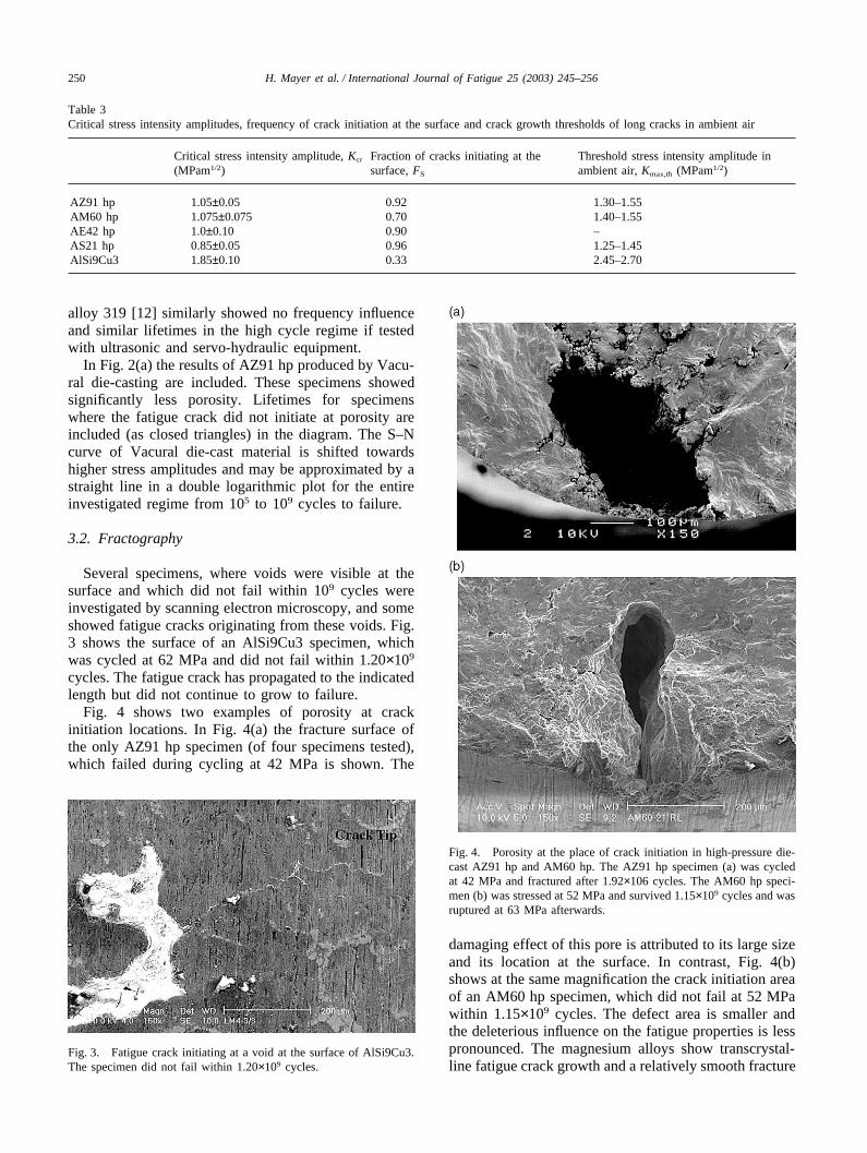
Several specimens, where voids were visible at thesurface and which did not fail within 109 cycles wereinvestigated by scanning electron microscopy, and someshowed fatigue cracks originating from these voids. Fig.3 shows the surface of an AlSi9Cu3 specimen, whichwas cycled at 62 MPa and did not fail within 1.20×10⁹
cycles. The fatigue crack has propagated to the indicatedlength but did not continue to grow to failure.
Fig. 4 shows two examples of porosity at crackinitiation locations. In Fig. 4(a) the fracture surface ofthe only AZ91 hp specimen (of four specimens tested),which failed during cycling at 42 MPa is shown. The
Fig. 3. Fatigue crack initiating at a void at the surface of AlSi9Cu3.The specimen did not fail within 1.20×10⁹ cycles.
Fig. 4. Porosity at the place of crack initiation in high-pressure die-cast AZ91 hp and AM60 hp. The AZ91 hp specimen (a) was cycledat 42 MPa and fractured after 1.92×10⁶ cycles. The AM60 hp speci-men (b) was stressed at 52 MPa and survived 1.15×10⁹ cycles and wasruptured at 63 MPa afterwards.
damaging effect of this pore is attributed to its large sizeand its location at the surface. In contrast, Fig. 4(b)shows at the same magnification the crack initiation areaof an AM60 hp specimen, which did not fail at 52 MPawithin 1.15×10⁹ cycles. The defect area is smaller andthe deleterious influence on the fatigue properties is lesspronounced. The magnesium alloys show transcrystal-line fatigue crack growth and a relatively smooth fracture

251H. Mayer et al. / International Journal of Fatigue 25 (2003) 245–256
Fig. 5. Distribution of defect areas, i.e. visible projection area withporosity at crack initiation location. Additionally, the mean diameterof the defects is indicated.
surface, whereas the fracture surface of AlSi9Cu3 isrougher.
The projected areas of the critical defects from whichfatal fatigue cracks initiated (defect areas) range from0.025 to 1.63 mm2. In Fig. 5 the defect areas and themean diameters of the defects are classified in a histo-gram. Table 4 shows the mean sizes of defect areas aswell as the maximum sizes of porosity found at crackinitiation locations of the five materials.
3.3. Critical stress intensity amplitude
Using Eq. (1) and assuming porosity as an initialcrack, the stress intensity amplitudes, Kmax of all testedspecimens were evaluated. In Fig. 6 the stress intensityamplitudes calculated for broken specimens (solidcircles) and runnouts (open circles) are shown. Theshaded regions indicate the regime of Kcr, i.e. wheresome specimens failed and others did not. The ranges ofthe critical stress intensity amplitudes are relatively
Table 4Mean and maximum diameter of area with porosity at the crackinitiation site
Mean defect Mean Largest Meanarea (mm2) diameter of defect area diameter of
defects (mm) (mm2) largest defect(mm)
AZ91 hp 0.27 0.59 0.95 1.10AM60 hp 0.23 0.54 1.63 1.44AE42 hp 0.20 0.50 0.61 0.88AS21 hp 0.26 0.58 0.86 1.05AlSi9Cu3 0.61 0.88 1.56 1.41
close, as shown in Table 3. The largest variation wasfound for AE42 hp (1.0±0.1 MPa√m), which means anuncertainty of ±10%, whereas closer ranges were foundin the other alloys.
The critical stress intensity amplitude can be used tocorrelate the most damaging porosity in a specimen toits critical stress amplitude, scr. With the size of porosity(Defect Area) and its location (at the surface or in theinterior) the critical stress amplitude is:
scr(Defect Area) �Kcr
a·�p·�Defect Area(2)
.The lower limit of Kcr may be used to calculate the
maximum stress amplitude the specimen can sustainwithout producing fatigue failure. The upper limitdefines the minimum stress level required for fatiguefailure within 109 cycles. Between these two values it isuncertain whether the specimen fails or not.
Since the most damaging porosity in all specimenshas been evaluated, the defect areas may be used forcorrelation with the fatigue limit. To establish a corre-lation between the distribution of defect areas and theprobability for failure at specific stress amplitudes, thedefect areas are statistically evaluated. In Fig. 7(a) and(b) the distributions of defect areas are presented in alog normal probability diagram. The ordinate indicatesthe probability of defect areas that are larger than thesize indicated on the abscissa. The probability of occur-rence of defect areas for the magnesium alloys isapproximately linear indicating the existence of a lognormal distribution. However, is less accurate todescribe AlSi9Cu3 as a log normal distribution, but tocompare the magnesium and aluminium cast alloys allmaterials were evaluated on the basis of the same distri-bution.
With the probability of occurrence, p the defect areaat the crack initiation location is greater than the defectarea (p), as shown in Fig. 7. To calculate the stressamplitude with fracture probability p, s(p), the defectarea (p), the critical stress intensity amplitude, Kcr andthe probability of crack initiation at the surface and inthe interior, respectively are required. If all specimensfail either after crack initiation at the surface or all failafter crack initiation in the interior, respectively, s(p)can be calculated by:
s(p) � � Kcr
a·�p·�Defect Area(p)
� (3)
If Fs is the fraction of specimens that failed by crackinitiation at surface porosity (Table 3) and (1�Fs) is thefraction failed by internal porosity, s(p) is determined

252 H. Mayer et al. / International Journal of Fatigue 25 (2003) 245–256
Fig. 6. Stress intensities of broken specimens (solid circles) and runnouts (open circles) assuming porosity at crack initiation as initial cracks.The shaded region indicates stress intensities, where failure as well as runnouts occurred, i.e. critical stress intensity amplitudes.
by the weighted geometric average:
s(p) �
� Kcr
0.65·�p·�Defect Area(p)
�Fs
(4)
·� Kcr
0.5·�p·�Defect Area(p)
�(1�Fs)
In Table 5 the stress amplitude with fracture prob-abilities of 0.50, 0.20 and 0.05 are summarised.
4. Discussion
A most interesting result of the present investigationis the existence of a fatigue limit in the magnesiumalloys AZ91 hp, AM60 hp, AE42 hp and AS21 hp andin the aluminium alloy AlSi9Cu3 if produced by high-pressure die-casting. Most specimens either fail below
2×10⁷ cycles or they survive 109 cycles or more. In fact,only two of 156 samples tested failed above 2×10⁷
cycles. Cast aluminium and magnesium alloys frequentlydo not show a fatigue limit. Rather S–N curves show amonotonic increase of lifetimes towards lower stresses(although sometimes with reduced slope) below several108 [3] or several 109 cycles [31].
The existence of a fatigue limit is not an inherent pro-perty of the investigated alloys but is caused by the cast-ing procedure leading to relatively large porosity. Test-ing similar alloys without porosity, like Vacural die-castAZ91 hp [Fig. 2(a)] or defect free gravity die-cast AZ91hp [14] no fatigue limit below 109 cycles was found.
Although a specimen did not fail within 109 loadcycles, fatigue cracks may have initiated at porosity,which is visible on the surface of some runnout speci-men. However, cyclic loading is too small to furtherpropagate the crack when a certain length is reached.The existence of a fatigue limit in the investigatedporous cast magnesium and aluminium alloys thereforeappears to be caused by non-propagating fatigue cracksrather than by a non-initiation condition.

253H. Mayer et al. / International Journal of Fatigue 25 (2003) 245–256
Fig. 7. Probability of occurrence of defect areas. The abscissa indi-cates the size of defect areas (and the respective mean diameters) andthe ordinate shows the probability that specimens contain porositylarger than the indicated size in AZ91 hp, AS21 hp and AlSi9Cu3 (a)and in AM60 hp and AE42 hp (b), respectively.
By equating porosity area to the initial crack size, acalculation of the critical stress intensity of failed andunfailed specimens is possible. It should be noted thatthe mean stress in samples containing large areas withporosity is increased due to the reduction of sound crosssection area. However, in the present study in comparedto the cross section of the samples (35 mm2) themaximum cross section containing porosity (1.63 mm2)is relatively small and cannot explain the variation ofcyclic properties of the different specimens. Rather thedetrimental effect of porosity and its influence on fatiguelifetimes and fatigue limit is a consequence of longer orshorter initial cracks attributed to different porosity size.
Using Kcr, calculations of fracture probabilities at cer-tain stress amplitudes are possible on the basis of thedistribution of defects. In the present investigation, frac-ture probabilities (Table 5) have been calculated usingthe probability of occurrence of defect areas shown inFig. 7. The probability diagrams have been obtained eva-luating crack initiating porosity in fatigue samples andare influenced by both, the quality of casting and thestressed volume, i.e. larger stressed volumes increase theprobability of large defects. If Kcr and Eq. (4) is used tocalculate stresses with different fracture probabilities ofactual components, the maximum sizes of porosity in therespective stressed volumes have to be determined eitherexperimentally (by X-ray studies, for example) or appro-priately predicted by numerical casting simulations.
The values of Kcr lie within a relatively close rangein all investigated materials, which indicates a strongcorrelation between this parameter and eventual fractureof a specimen. This is remarkable, since inaccuratedetermination of the stress intensity using Eq. (1), disre-garding the degree of porosity at the place of crackinitiation and statistical scatter of crack propagationproperties in grains of different orientation and differentsize adjacent to defect areas might influence the determi-nation of Kcr.
The critical stress intensity amplitudes can be com-pared to threshold values of long fatigue cracks of thesame alloys at a load ratio R=�1 (Table 3)[32]. Thequantity of Kcr of the investigated alloys is approx. 60–75% of the threshold stress intensity of long cracks. Thismeans that a calculation of the fatigue limit on the basisof the threshold of long cracks would overestimate it.This is consistent with observations of short cracks,which may grow at cyclic stress intensities below thelong crack threshold [33]. Effective stress intensity thre-sholds have been determined for a number of aluminiumalloys and show a value between 0.8 and 0.9 MPa√m[34]. The effective threshold stress intensity of sand castAZ91E-T6 has been determined to be approx. 0.7MPa√m [35]. No experimental data were found in theliterature for the other magnesium alloys. The criticalstress intensities of high-pressure die-cast AZ91 hp andAlSi9Cu3 are higher than the effective thresholds. If the

254 H. Mayer et al. / International Journal of Fatigue 25 (2003) 245–256
Table 5Calculated stress amplitudes for different fracture probabilities using Eq. (4) (in MPa)
Fracture probability AZ91 hp AM60 hp AE42 hp AS21 hp AlSi9Cu3
0.50 43–47 50–55 41–48 34–38 71–730.20 35–39 40–44 35–41 28–32 59–610.05 29–32 33–36 30–36 24–27 49–51
critical stress intensity amplitudes found in the experi-ments are interpreted in terms of crack closure thismeans, that closure level of arrested cracks originatingfrom porosity are lower than those of long cracks. Themost frequent diameter of porosity of the investigatedalloys is 0.50–0.88 mm (Table 4), which means thatthese cracks should be considered as short cracks. It istherefore plausible that the critical stress intensities arebelow the long crack threshold stress intensity.
The critical stress intensity amplitude may be used tocompare the influence of defects on the investigatedalloys. Statistical distributions of defect areas in AZ91hp and AS21 hp [Fig. 7(a)] are closely similar. However,Kcr of AS21 hp (0.85±0.5) is approx. 20% lower than ofAZ91 hp (1.05±0.05). By about a similar magnitude, theS-N curve of AS21 hp is shifted towards lower stresses,since porosity being more deleterious in AS21 hp. Obvi-ously AS21 hp is less defect tolerant with respect toporosity when compared to AZ91 hp.
Several methods to treat defects in materials aredescribed in the literature. Murakami and Endo [36]summarised different methods, which use the meandiameter of a defect or the square root of its projectedarea, (area)1/2 for correlation with the threshold cyclicstress intensity of cracks originating from these defects,�Kth and with the fatigue limit, sW:
�Kth���area�1/n
⇒snw·��area� � const. (5)
They showed for different defect sizes in steels thatn=6, if the defects are small (3–200 µm), whereas anexponents n=3 may better describe defects or notcheslarger than 100 µm [36]. The effect of small defectscould be well predicted for a wide range of materialsusing Vickers Hardness (HV) and the area of the flaw(area, in µm2). Using b=1.43 for surface flaws andb=1.56 for internal defects the fatigue limit, sW is [37]:
sw �b·(HV � 120)
(�area)1/6(6)
.For the investigated magnesium alloys, however, a
mean fatigue limit of 83–87 MPa would be predicted,which is approximately a factor of 2 higher than actuallymeasured. The calculated mean fatigue limit ofAlSi9Cu3 is expected at 103 MPa, which is approxi-
mately a factor of 1.4 higher than the experimentalresult.
The method used in this investigation implicitly usedn=2 relating Kcr to stress amplitudes with different frac-ture probabilities and defect areas in Eq. (4). The rela-tively close regime of Kcr observed supports the useful-ness of this concept for the investigated materials. Thereasons for the validity of the concept are probably that(nearly) all fatigue cracks initiated at relatively largeporosity and that the variation of porosity size at thecrack initiation location is not too large (mean diametersvary from 0.18 to 1.40 mm). However, as defect sizesbecome smaller their deleterious influence on the cyclicstrength will be greater than predicted on the basis of astress intensity concept using n=2 [38]. The criticalstress intensity amplitude may be used therefore to pre-dict the (technically important) influence of largeporosity on the fatigue limit, however, becomes invalidfor small defect sizes. Moreover, assuming porosity asthe only possibility of crack initiation would predictinfinite fatigue strength of specimen produced by Vacu-ral die-casting, for example. Similar to cast aluminiumalloys, fatigue cracks initiate at defects other thanporosity or by slip in preferentially oriented grains if thesize of porosity is small.
5. Conclusion
The fatigue properties of magnesium alloys AZ91 hp,AM60 hp, AE41 hp and AS21 hp and of aluminiumalloy AlSi9Cu3 produced by high-pressure die-castinghave been investigated in ambient air in the regime of105 to 109 cycles.
� AZ91 hp and AM60 hp show the best fatigue proper-ties among the investigated magnesium alloys. AE42hp shows slightly worse fatigue properties, and thelowest cyclic strength was found for AS21 hp. AM60hp and AZ91 hp reach approx. 60–70% of the cyclicstrength of AlSi9Cu3.
� In 98.5% of specimens the fatigue crack initiated atporosity. The smallest area with porosity at crackinitiation location was 0.025 mm2 (mean diameter0.18 mm). Porosity in magnesium alloys greater thanthis value may be considered as the most important

255H. Mayer et al. / International Journal of Fatigue 25 (2003) 245–256
material defect for high cycle fatigue and fullyreversed loading conditions.
� All investigated alloys show a pronounced fatiguelimit. At the fatigue limit cracks may initiate atporosity but do not propagate to failure.
� If porosity is considered as equivalent to an initialcrack, the fatigue limit can be correlated to criticalstress intensity amplitude, Kcr. The probability forfailure at different stress amplitudes is determined byKcr, the probability of porosity to exceed a certain size(area) and the probability of crack initiation either atthe surface or in the interior.
� Similar fatigue behaviour was found for cast magnes-ium alloys for tests conducted at 20 000 and at 50 Hz,indicating that ultrasonic fatigue testing is equivalent,for the test conditions examined, to standard low fre-quency testing.
Acknowledgements
Investigations were financed by the AUDI AG, Ingol-stadt, which is gratefully acknowledged. The authorsthank Prof J.W. Jones, Univ. of Michigan, for help pre-paring the manuscript.
References
[1] Aghion E, Eliezer D, editors. Proc. of 1st Israeli Int. Conf. onMagnesium Sci. and Technol., Dead Sea, Israel. MagnesiumResearch Insitute; 1997.
[2] Mordike BL, Kainer KU, editors. Magnesium alloys and theirapplications. Wolfsburg: Werkstoff-Info GmbH Frankfurt; 1998.
[3] Henry SD, Davidson GM, Lampman SR, Reidenbach F, BoringRL, Scott WW, editors. Fatigue data book: light structural alloys.Materials Park, OH: ASM International; 1995.
[4] Wang QG, Apelian D, Griffith JR. In: Microstructural effects onthe fatigue properties of aluminum castings, Proc. Materials Sol-utions 98, Rosemont, IL, USA. Materials Park, OH: ASM Inter-national, Member/Customer Service Center; 1998. p. 217–33.
[5] Couper MJ, Neeson AE, Griffith JR. Casting defects and thefatigue behavior of an aluminium casting alloy. Fatigue FractEngng Mater Struct 1990;13(3):213–27.
[6] Ting JC, Lawrence FV. Modeling the long-life fatigue behaviorof a cast aluminium alloy. Fatigue Fract Engng Mater Struct1993;16(6):631–47.
[7] Skallerud B, Iveland T, Harkegard G. Fatigue life assessment ofaluminium alloys with casting defects. Engng Fract Mech1993;44(6):857–74.
[8] Sonsino CM, Ziese J. Fatigue strength and application of castaluminuium alloys with different degrees of porosity. Int JFatigue 1993;15(2):75–84.
[9] Stanzl-Tschegg SE, Mayer HR, Tschegg EK, Beste A. In-serviceloading of AlSi11 aluminum cast alloy in the very high cycleregime. Int J Fatigue 1993;15(4):311–6.
[10] Boileau JM, Zindel JW, Allison JE. The effect of solidificationtime on the mechanical properties in a cast A356-T6 aluminumalloy. SAE Transactions: J Mater Manufact 1997;106(5):63–74.
[11] Dabayeh AA, Xu RX, Du BP, Topper TH. Fatigue of cast alu-
minium alloy under constant and variable-amplitude loading. IntJ Fatigue 1996;18(2):95–104.
[12] Caton MJ. Predicting fatigue properties of cast aluminium bycharacterizing small-crack propagation behavior. Ph.D Disser-tation, University of Michigan, Ann Arbor, MI, 2001.
[13] Zhang B, Poirier DR, Chen W. Microstructural effects on high-cycle fatigue-crack initiation in a 356.2 casting alloy. Met TransA 1999;30A:2659–66.
[14] Mayer H, Lipowsky H, Papakyriacou M, Rosch R, Stich A,Stanzl-Tschegg S. Application of ultrasound for fatigue testingof lightweight alloys. Fatigue Fract Engng Mater Struct.1999;22:591–9.
[15] Buffiere JY, Savelli S, Jouneau PH, Maire E, Fougeres R. Experi-mental study of porosity and its relation to fatigue mechanismsof model Al-Si7-Mg0.3 cast Al alloys. Mater Sci Engng2001;A316:115–26.
[16] Caton MJ, Jones JW, Boileau JM, Allison JE. The effect of solidi-fication rate on the growth of small fatigue cracks in a cast 319-type aluminium alloy. Met Mater Trans A 1999;30A:3055–68.
[17] Stanzl-Tschegg S, Mayer H, editors. Proceedings of the Inter-national Conference on Fatigue in the Very High Cycle Regime.Vienna: Institute of Meteorology and Physics, BOKU; 2001.
[18] Stanzl-Tschegg SE, Mayer HR, Beste A, Kroll S. Fatigue andfatigue crack propagation in AlSi7Mg cast alloys under in-serviceloading conditions. Int J Fatigue 1995;17(2):149–56.
[19] Ogarevic VV, Stephens RI. Fatigue of magnesium alloys. AnnuRev Mater Sci 1990;20:141–77.
[20] Donlon WT, Paige C, Morris CJ, Allison JE. The effects of cast-ing defects and microstructure on the mechanical properties ofdie cast AM50 magnesium and 356 aluminum. In: Proc Alumi-num and Magnesium for Automotive Applications. Cleveland,OH: Minerals, Metals and Materials Society/AIME (USA); 1996.p. 17–27.
[21] Mayer H, Lipowsky H, Papakyriacou M, Rosch R, Stich A, ZettlB, Stanzl-Tschegg S. Fatigue properties of high pressure die castmagnesium alloys at high numbers of cycles. In: Proc 7th IntFatigue Conf, Beijing, China. Beijing, China: Higher EducationPress; 1999. p. 2059–65.
[22] Liu Z, Wang Z, Wang Y, Liu Z. Cyclic deformation behaviourof high pressure die casting alloy AM50. J Mater Sci Lett1999;18:1567–9.
[23] Rodrigo D, Murray M, Mao H, Brevick J, Mobley C, Chandrase-kar V, Esdaile R. Effects of section size and microstructural fea-tures on the mechanical properties of die cast AZ91D andAM60B magnesium alloy test bars. SAE Transactions: J MaterManuf 1999;108:785–9.
[24] Wendt J, Hilpert M, Kiese J, Wagner L. Surface and environmen-tal effects on the fatigue behavior of wrought and cast magnesiumalloys. In: Proc Magnesium Technology 2001, TMS AnnualMeeting, New Orleans, LA, USA. Warrendale, PA: Minerals,Metals and Materials Society/AIME; 2001. p. 281–5.
[25] Mayer H. Fatigue crack growth and threshold measurements atvery high frequencies. Int Mater Rev 1999;44(1):1–36.
[26] Schindelbacher G, Rosch R. Mechanical properties of magnesiumdie casting alloys at elevated temperatures and microstructure independence of wall thickness. In: Proc Magnesium Alloys andtheir Applications. Wolfsburg: Werkstoff-Info GmbH Frankfurt;1998. p. 247–52.
[27] Murakami Y, Endo M. The area parameter model for smalldefects and nonmetallic inclusions in fatigue strength: experi-mental evidences and applications. In: Proc Theoretical Conceptsand Numerical Analysis of Fatigue, Birmingham, UK. Warley:Engineering Materials Advisory Services Ltd., Cradley Heath;1992. p. 51–71.
[28] Murakami Y. Stress Intensity Factors Handbook. vol. 1, pp. 810-812 Oxford: Pergamon Press, 1987.
[29] Mayer H, Papakyriacou M, Pippan R, Stanzl-Tschegg S. Influ-

256 H. Mayer et al. / International Journal of Fatigue 25 (2003) 245–256
ence of loading frequency on the high cycle fatigue properties ofAlZnMgCu1.5 aluminium alloy. Mater Sci Engng2001;A314:51–7.
[30] Stanzl-Tschegg SE, Mayer HR. Fatigue and fatigue crack growthof aluminium alloys at very high numbers of cycles. Int J Fatigue2001;23(S2001):231–7.
[31] Mayer H, Papakyriacou M, Stanzl-Tschegg S, Tschegg E, ZettlB, Lipowsky H, Rosch R, Stich A. Korrosionsermudung verschie-dener Aluminium- und Magnesium-Gußlegierungen. Materialsand Corrosion 1999;50:81–9.
[32] Mayer H, Stanzl-Tschegg S. Environmental influences at veryhigh frequency. In: Proc of Int Conf. on Fatigue in the Very HighCycle Regime. BOKU, Vienna: Institute of Metals and Physics;2001. p. 267–74.
[33] Pearson S. Initiation of fatigue cracks in commercial aluminiumalloys and the subsequent propagation of very short cracks.Engng Fract. Mech 1975;7:235–47.
[34] Pippan R. The effective threshold of fatigue crack propagationin aluminium alloys, Part I: influence of yield stress and chemicalcomposition. Phil Mag 1998;77(4):861–73.
[35] Goodenberger DL, Stephens RI. Fatigue of AZ91E-T6 cast mag-nesium alloy. Trans ASME J Engng Mat Techn1993;115(4):391–7.
[36] Murakami Y, Endo M. Effects of defects, inclusions and inhom-ogeneities on fatigue strength. Int J Fatigue 1994;16(3):163–82.
[37] Murakami Y, Endo M. Effects of hardness and crack geometrieson �Kth of small cracks emanating from small defects. In: Proc.the Behaviour of Short Fatigue Cracks. London: EGF, MechEngng Pub; 1986. p. 27–293.
[38] Kitagawa H, Takahashi S. Applicability of fracture mechanics tovery small cracks or the cracks in the early stage. In: Proc SecondInternational Conference on Mechanical Behavior of Materials.New York: American Society for Metals; 1978. p. 627–31.