Introductory Lecture Photonic Networksdrzaidi.seecs.nust.edu.pk/lectures/Lec-1 Introduction...
56
Introductory Lecture on Photonic Networks
Transcript of Introductory Lecture Photonic Networksdrzaidi.seecs.nust.edu.pk/lectures/Lec-1 Introduction...

Introductory Lecture on
Photonic Networks

Motivation and ObjectivesThe idea behind the all-optical networking is to maximize the transmission distance and deliver transparent and flexible connections. Keeping it all optical will result in cost reduction both in capital as well as in operations. It will lead to an ultimate realization of the Optical Internet.
Limiting Optical-Electrical-Optical (OEO) conversions to mainly the ingress and egresspoints of the network, and thus reducing the amount of equipment that needs to be installed to add capacity to the network, should achieve the economic gains. A number of Ultra-Long-Haul (ULH) system vendors have promoted such a benefit but none to date have fulfilled the promise.

Some HistoryOptical Communication is not new!
Alexander Graham Bell’s Photophone, 1880

.The Network Life Cycle
.*Source: From Bell to Broadband, Professor Keith Ward of University College London
TelegraphNetwork
ManualTelephoneNetwork
SwitchedAnalog
TelephoneNetwork
DigitalNetwork
1880 1890 1900 1910 1920 1930 1940 1950 1960 1970 1980 1990 2000
BroadbandNetwork
VF TelexMessaging Magneto
AudioAmplifiers
SleeveControl
Switchboard
ElectricalExchange
CoaxSystems
VF Signaling PCM
ISDN
SONET/SDH
Intelligent Network
#7 Signaling
ATMIP
DWDM

Transmission Media• Transmission Medium, or channel, is the actual physical
path that data follows from the transmitter to the receiver.
• Copper cable is the oldest, cheapest, and the most common form of transmission medium to date.
• Optical Fiber is being used increasingly for high-speed applications.
Fiber Replaces Copper

Fiber Optics

.Fiber Optic Transmission Bands
.
Near InfraredFrequency
Wavelength1.6
229
1.0 0.8 µm0.6 0.41.8 1.4
UV
(vacuum) 1.2
THz193 461
0.2
353
Longhaul Telecom
Regional Telecom
Local Area Networks850 nm
1550 nm
1310 nmCD Players780 nm
HeNe Lasers633 nm
C=νλ /n

Why Optical ?
• Growing demand for faster and more efficient communication systems
• Internet traffic is tripling each year• It enables the provision of Ultra-high
bandwidth to meet the growing demand• Increased transmission length• Improved performance• etc.

Demand for Bandwidth
BandwidthDemand
1990 2000 2010
• Raw text = 0.0017 Mb• Word document = 0.023 Mb• Word document with picture = 0.12 Mb• Radio-quality sound = 0.43 Mb• Low-grade desktop video = 2.6 Mb• CD-quality sound = 17 Mb• Good compressed (MPEG1) video = 38 Mb
Typical data bandwidth requirement
20,000 x

Light Provides more BandwidthBandwidth is the range of frequencies employed to transmit (communicate) a signal (information)More bandwidth = more information.
Typical Signals:Audible Sound-waves (20 to 20,000 cycles/s)AM radio uses 10kHzFM radio uses 100kHzTV uses 6MHz rangeSignals: sound = a variation in air pressure
loudness = the amplitude of the variationpitch = the frequency of the variationwavelength = speed of propagation
pitchΛs: 1100ft/sec = 2.5 ft.
440Hz

•• After After ShoaShoa--Kai LiuKai LiuDirector Director -- Network Technology Development; WorldComNetwork Technology Development; WorldCom
All-Optical Network(Terabits ⇒ Petabits)
TDM DWDM
0
5
10
15
20
25
30
35
40
Ban
dwid
th
8λ @OC-484λ @OC-192
4λ @OC-48
2λ @OC-48
2λ @1.2Gb/s(1310 nm, 1550 nm)
10 Gb/s
2.4 Gb/s1.2 Gb/s565 Mb/s
1.8 Gb/s810 Mb/s405 Mb/s
EnablersEDFA + Raman AmplifierDense WDM/FilterHigh Speed OptoelectronicsAdvanced Fiber
1982
1984
1988
1994
1996
1998
2000
2002
1990
1986
1992
16λ @OC-192
40 Gb/s
32λ @OC-192
176λ @OC-192
2004
2006
TDM (Gb/s)
EDFA
EDFA +Raman Amplifier
80λ @ 40Gb/s
Bandwidth Evolutionary LandmarksBandwidth Evolutionary Landmarks

Point-to-Point Optical Linka building block for backbone and all-optical networks.
Tx/RxE
Tx/RxE
DLaserAPDA
ModFThresh
DLaserAPDA
ModFThresh

The Need for Photonic Networks
Node A
Node J
Node C
Node BRegeneratoror amplifier
Circuit
Path
Media
• Optics is used only for point to point links• All other functionality is in the electronics
– frequent switching enables high utilisation of transmission link

The Need for Photonic Networks
Transmitter ReceiverTransmitter Receiver
Transmitter Receiver
Transmitter Receiver
Transmitter Receiver
Transmitter ReceiverTransmitter Receiver
Transmitter Receiver
WDM + amps saves regenerators + fibre
Increasing transmission capacityIncreasing transmission capacity by by Wavelength Division MultiplexingWavelength Division Multiplexing
(WDM)

The Need for Photonic Networks
Capacity(log scale)
1990 2000
2Mb/s8Mb/s
34Mb/s
140Mb/s565Mb/s
2.5Gb/s
10Gb/s 4λ
8λ16λ
32λ
64λ
128λ
1980 1985 1995
Year
1 Tb/s
TDM
WDM now
WDM soon
Growth of transmission capacity with time

The Need for Photonic Networks
40x2.5 16x10 40x1032x2.5 80x2.5 32x10
Capacityper fibre
(Gb/s)
64x10
Compiled from information in vendor web sites
16x2.50
100200300400500600700
•OADM and optical protection features also available
•40Gb/s systems around the corner?
Capacity of existing or announced WDMCapacity of existing or announced WDM productsproducts

Bandwidth and Capacity
First Generation
Wideband
35nm; 80ch
Ultra-Wideband
80nm; 200chEnables TerabitSystems !

Optical Technology - Advantages
• High data rate, low transmission loss and low bit error rates• High immunity from electromagnetic interference• Bi-directional signal transmission• High temperature capability, and high reliability• Avoidance of ground loop• Electrical isolation• Signal security• Small size, light weight, and stronger
448 copper pairs5500 kg/km
62 mm
21mm648 optical fibres
363 kg/km

Importance of Optical Networks
• The services provided by Optical Technology are:– Next Generation Internet Internet 2– IPTV– Video Conferencing– Online Gaming– And many more

Applications
Optical Communication SystemsHigh Speed Long Haul Networks (Challenges are transmission type)
Metropolitan Area Network (MAN) ?Access Network (AN)?Challenges are:
- Protocol- Multi-service capability- Cost
Electronics and ComputersBroad OptoelectronicMedical ApplicationInstrumentation
Optics
is he
re to
stay f
or
a lon
g tim
e.
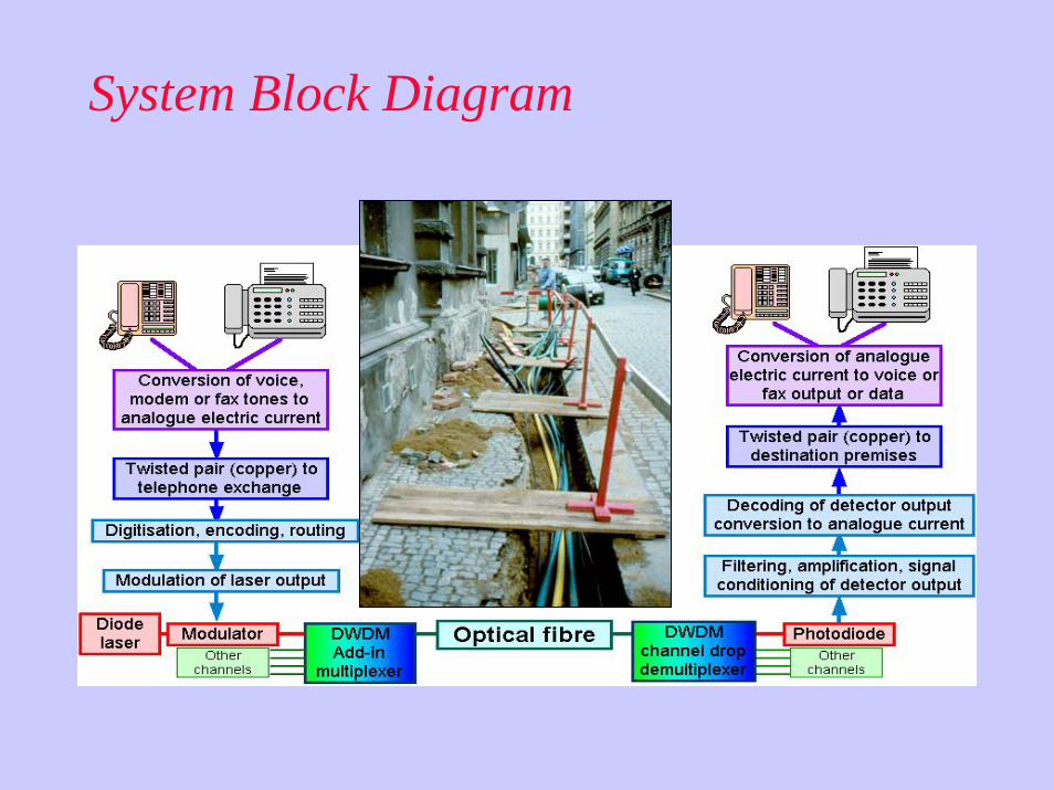
Evolution of Photonic Networks• Further increase in transmission capacity of TDM lines to 40
Gb/s (ETDM) and above (OTDM)• Further increase in number of wavelengths above 100• Intelligent electrical at border of transparent optical core• Wavelength switching devices introduced in network core• IP routers with optical interfaces deployed• IP routers combined with OADMs and OXCs equipped with
optical interfaces enabling optical bypass

Evolution of Photonic Networks• New kinds of network elements optimized for
packet switching/routing. UNI between electronic routers and optical network elements and NNIbetween optical network elements with control and signalling capability
• Integrated protocols and algorithms for traffic engineering, path establishment, protection and restoration in the optical layer coordinated with IP layer will be developed

Evolution of Photonic Networks
Fibre level
Wavelengthchannel
level
Sub-wavelength
level
Incr
easi
ng re
solu
tion
Manualprovisioning
Remoteprovisioning
Dynamicprovisioning
Fibrepatchpanels
Opaque‘Oparent’
Transparent
Digital cross-connect
Tbitrouter
‘Oparent’packet router
Transparentphotonic
packet router

Network Evolution
– High Capacity Transmission
– Automated Connection Provisioning – Flexible Adjustment of Bandwidth– Network Self-Healing/Restoration
WDM/Point-to-Point Transport
– Fixed Sharing Between Multiple Nodes – Passive Access of Wavelength Channels
Fixed WDM/Multipoint Network
Photonic XC and WADMReconfigured WDM Network
Fiber Amplifier
Wavelength Mux/DMux
Wavelength Add/Drop
Wavelength Cross-Connect

.
WDM Adds a New Dimension
.
Power
Wavelength
Time
• Cross-phase modulation
• Laser power• Fiber attenuation• Component and system losses
• Fiber PMD• Fiber dispersion• Jitter• Transmission rate
• EDFA bandwidth• Central wavelength
stability • BW stability
• EDFA ASE• EDFA gain• Crosstalk• 4W mixing• Raman FS• Brillouin BS
• Laser chirp• Chromatic dispersion• DGD
• Modulation• Self-phase mod.• BER

.

Anatomy of a DWDM system
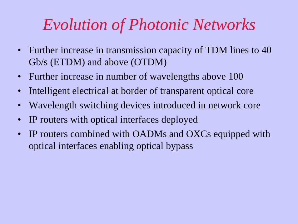
All Optical Network
SDH
ATM
IP
SDH
ATM
IP
Open Optical Interface
SDH ATM IP Other
All Optical Networks
Challenges ahead:• Network routing• Network routing • True IP-over-optics• True IP-over-optics• Network protection• Network protection

Undersea Cables
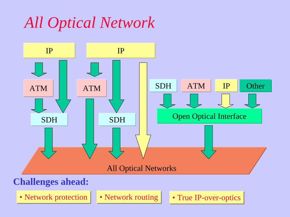
System Block Diagram

Architecture of Photonic Networks
Tx-1
Tx-2
Tx-N
mux
OADM
OXC
Rx-1
Rx-2
Rx-N
demux
transmitterswavelength defined,
high speed?
multiplexergratings,couplers,
filters
fibredisp compensation?
nonlinearities?
optical amplifierEDFA?
gain flattened?
optical add-dropmultiplexer:
couplers, filters, circulators
optical cross -connect
couplers, amplifiers,filters , switches
demuxgratings,couplers,
filters
receivers
Network devices:

Key Functional Blocks
• Transceivers (LD, PD, Mod.)DFBs, VCSELs
• Optical Amplifiers (EDFAs, SOAs,Raman)
• DWDM (Sources, Mux/ de-Mux)
• Tunable Filters / OADMFBGs, FPs
• Switching/Routing
• Optical Circulators
Tx/Rx
E
OA
Mux
1 2
3

TransceiversCrucial building blocks
• Transmitters (LDs, LEDs, Drivers/ Modulators)(Precision Tunable Laser arrays needed for DWDM)
• Modulators (External, data source)
• Receivers (PDs, Pre-Amp, Filters)
signal outD Laser
APDA
Mod
FThreshsignal in
Data in

Source
SourcecodingSourcecoding ModulationModulation MultiplexingMultiplexing ModulationModulation
ExternalExternal InternalInternal
• Analogue• Digital• Analogue• Digital
• Frequency• Time• Frequency• Time
• Pulse shaping• Channel coding• Encryption• etc.
• Pulse shaping• Channel coding• Encryption• etc.

Receiver
1st-stageamplifier1st-stageamplifier
2nd-stageamplifier2nd-stageamplifier
Pre-detectionfiltering
Pre-detectionfiltering
Sampler&
detector
Sampler&
detector
DemultiplexerDemultiplexer
• Equalizer DemodulatorDemodulator
Output signalOutput signal
DecoderDecryptionDecoder
Decryption

Light Sources
Semiconductor lasers, LEDs and particularly VCSEL’s remain an important area for further work.
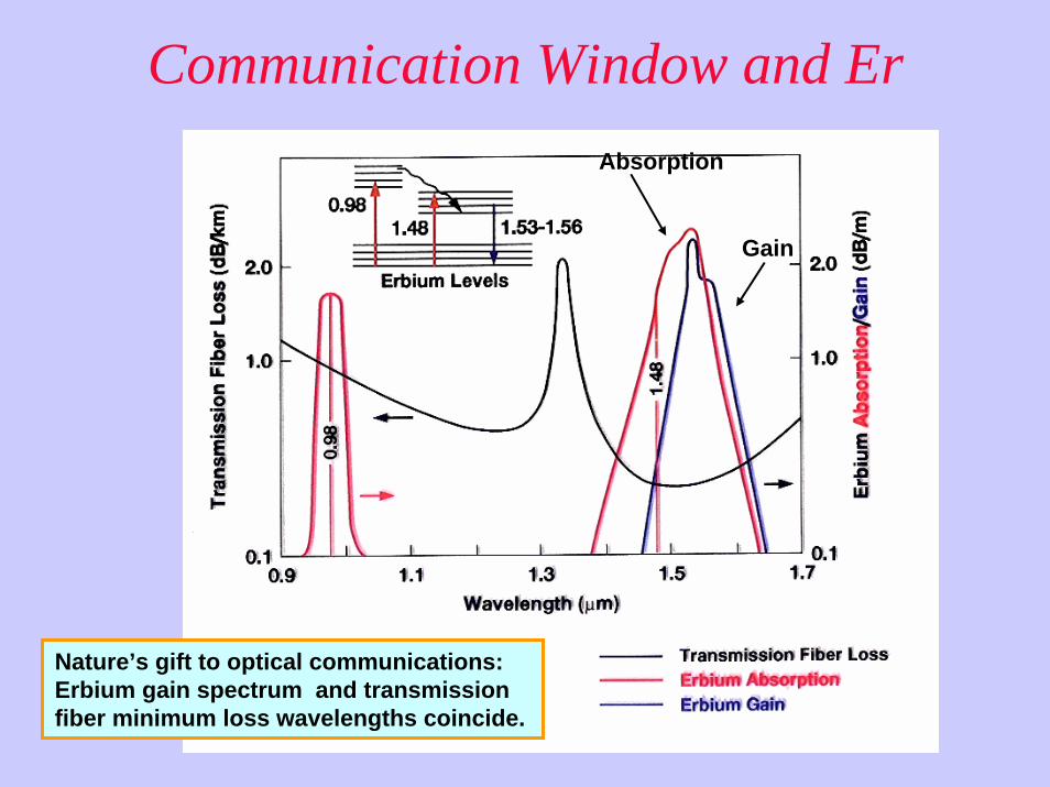
Communication Window and Er
Nature’s gift to optical communications: Erbium gain spectrum and transmission fiber minimum loss wavelengths coincide.
Gain
Absorption

EDFA: A Key Enabler for WDM
Data OutWDM Point-to-Point
XMTR OMUX
Data In
OAXMTR
XMTR
OA
RCVR
RCVR
RCVR
ODMUX
•••••
•••••
λ1
λ2
λN
λ1
λ2
λN
OAOA
• High power• Low noise figure • Bit-rate transparent• No cross-talk• Wide bandwidth• Excellent mech. property • and more …

Optical Amplifiers (EDFA)Erbium doped fiber amplifiers permit the boosting of optical signals within the fiber, without the o-e-o conversion that limits bit rates!
These work exactly in the range of frequencies, 1525 - 1620 nm, cover whole third window !
This technology permits long haul transmission and, more importantly, enables:
Wavelength Division Multiplexing (WDM)
Today EDFAs Exist in S-band, C-band and L-band

Optical Isolators and Circulators
.
1 2
3
0o 45o 45o
PT
PR
Pi
Faraday Rotator
90o
Combination of Isolators make up a Circulator

.
.
1-λOADM
Out
Drop Add
In1 2
3 2 31
Opticalcirculator
Opticalcirculator
FBGλBragg = λ3
Fiber Bragg Gratings (FBG)
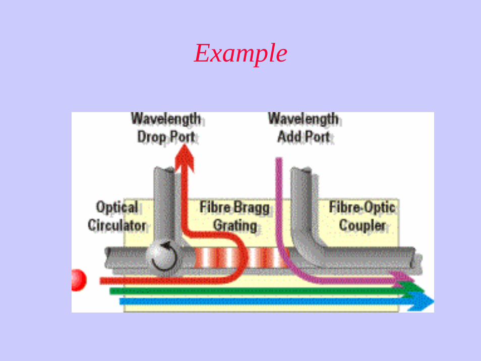
Example

OADM Technologies
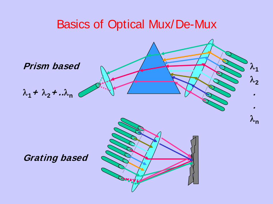
Basics of Optical Mux/De-Mux
Prism based λ1
λ2
λ1+ λ2+..λn ..
λn
Grating based

Sub-Multiplexing and Multiplexing
.

.
.
DWDM ComponentsMEMS Switch
Technology

Opaque / Translucent Optical Switch
.Transponders1310 nm Optical Switching Fabric
Add traffic
Transponders
Output Fibers
Input Fibers
Optical Layer X-connect Opto-
electronic
Drop traffic
Output Fibers
Transparent Optical Switching Fabric without λ−Conversion
Optical Space Switch
λ2
Input Fibers
Optical Space Switch
λ1
Optical Space Switch
λn
Transparent Optical Switch Architecture
Optical Cross Connects (OXCs)

Chromatic dispersion PMD Non-linear effectsDispersion and non-linear effects
Fiber Related Problems
P
λ

Chromatic Dispersion
60 Km SMF-28
4 Km SMF-28
40 Gbps
t
10 Gbps
t
• It causes pulse distortion, pulse "smearing" effects
• Higher bit-rates and shorter pulses are less robust to Chromatic Dispersion
• Limits "how fast“ and “how far” data can travel

Polarization Mode Dispersion (PMD)
• The optical pulse tends to broaden as it travels down the fibre; this is a much weakerphenomenon than chromatic dispersion and it is of some relevance at bit rates of 10Gb/s or more
nx
nyEx
Ey
Input pulse Spreaded output pulse

Challenges AheadModulation and detection and associated high speed electronicsMultiplexer and demultiplexerFibre impairments:
. Loss
. Chromatic dispersion
. Polarization mode dispersion
. Optical non-linearity
. etc.
Optical amplifier . Low noise . High power . Wide bandwidth. Longer wavelength band S

Challenges Ahead
Dedicated active and passive componentsOptical switches managementAll optical regeneratorsNetwork protectionInstrumentation to monitor QoS

Optical Transport Network
Global Network
Wide Area Network
Metropolitan/Regional Area Optical Network
Corporate/Enterprise Clients
Cable modemNetworks
Client/Access Networks
FTTHMobile
SDH/SONET
ATM
PSTN/IP
ISPGigabit Ethernet
Cable
FTTB
ATM
< 10000 km< 10 Tbit/s
< 100 km< 1 Tbit/s
< 20 km100M - 10 Gbit/s

Types of MPLS NodesThere are three types of MPLS nodes as shown in diagram and perform the following
functions.
EgressLSR UserUser
IngressLSR
TransitLSR
TransitLSR
TransitLSR
TransitLSR
Ingress LSR receives native-mode traffic (e.g. IP datagram) and classifies into FEC. It then generates Generates MPLS header and assign it initial label. IP datagram encapsulated into MPLS packet with MPLS header attached to datagram. Integrated with QOS operations (if applicable).
Transit, Interior, or core LSR receivers the packet and use MPLS header to make forwarding decision. It processes label header only and performs label swapping.
Egress LSR receives performs decapsulation operations (it removes the MPLS header).

Resources & facilities @ NIIT• Optsim• Access to vast online digital data
– IEEE (Comm Magazine, Comm letters, Photonic TechnlogyLetters (PTL), Journal of Lightwave Technology (JLT), Journal of Selected Areas in Communications (JSAC), etc
– ACM• Focussed Networking Research group with strong
international Collaborations (Stanford (PNRL), UNCC (Center for optoelectronics and optical communications), North Carolina Research Triangle, TTU, US
• Participation in International GLIF project• HONET Workshop/Symposia

Concluding Remarks• We have given a selective overview of Optical Networks
architecture from physical layers perspective
• Optical components technologies will undergo a major revolution for next generation all-optical internet !!
• Demand for low-cost high-quality active and passive components and modules,e.g. DWDM Interleavers, ROADMs, Optical Circulators, Mux/de-mux, Dispersion-compensating elements, OAs and Dynamic gain-flattening filters, and so on...is felt
• GMPLS supports the evolving OTN that will accommodate all type of traffic with a high level of reliability and transparency