
introduction_to_medical_imaging
62
Introduction to Medical Imaging Xiaochen Xu [email protected] Eduardo Bartolome [email protected] Medical Business Unit Texas Instruments March, 2010
-
Upload
rezgar-shahi -
Category
Documents
-
view
88 -
download
0
Transcript of introduction_to_medical_imaging

Introduction to Medical
Imaging
Xiaochen Xu
Eduardo Bartolome
Medical Business Unit
Texas Instruments
March, 2010

Agenda
• TI in Medical Market
• Ultrasound Imaging
– Principles
– System Considerations
• Other Imaging Modalities
– X-ray Imaging
– CT Imaging
• Medical Image Safety

TI in Medical Market

TI Commitment to MedicalCommitted for the long term
• Dedicated Medical Business Unit (MBU) Organization combines expertise from Military/Automotive to support Medical customers with for enhanced products, quality and services.
Investing in Innovation
• R&D• Venturing (funded)• Partnering (co-marketing, design, etc)• University Programs -$15M
Driving standards
• Continua Health Alliance (interoperable telehealth)
• IEEE-11073 (medical communication)• iNEMI MCRS (medical component
reliability)

DSPHigh
Performance
Medical
Low
Power
Medical
TI Medical Organization
HPA
Medical BU
Medical / High Rel
Analog
Signal
Chain
Wireless
Connectivity
Implant-
ables
WW Strategic Marketing
Legal
MSP430
RFID
Power
Regional Medical Champions
TI Proprietary – Strictly Confidential

Quality & reliabilityQuality & reliability
Processtechnology
Processtechnology
Sales & applications support
Sales & applications support
• Broad analog and digital catalogportfolio
• Broad analog and digital catalogportfolio
TI Medical offering
• Application-specific products
• TI investments
• Dedicated resources
Bluetooth®
• University research
• VC investment
• New technologies
• Implantables
Implantable
Bluetooth®
ULP
????
AmplifierData Converter
DSP
MSP430
TI Proprietary – Strictly Confidential

Medical overview
Broadest portfolio of analog and embedded processing solutions in the market

MRI
Hyperspectral Imaging3D/4D imagers
Ultrasound
PET / CT / OCT
Digital X-ray
Vein viewer
Medical imaging modalities

• High-perfor-mance DSPs
• Digital signal controllers
• High-perfor-mance DSPs
• Digital signal controllers
• High-perfor-mance DSPs
• Digital signal controllers
• High-perfor-mance DSPs
• DaVinci™-based SoCs
• Low power OMAP35xapplicationprocessors
• High-perfor-manceDSPs*
• Digitalsignal controllers
Embeddedprocessors
PETX-rayMRIUltrasoundCT
Complete IC portfolio for medical imaging
*high-performance DSPs include multi-core, single-core and floating point
Power management, data converters, amplifiers, clocks, interfaces, switches
CatalogAnalog
• Amplifiers• Analogfront ends
• Dataconverters
• Analogfront ends
• Pulsers and switches
• Analogfront ends
• Dataconverters
Application-specific Analogproducts

Ultrasound
*@?!?
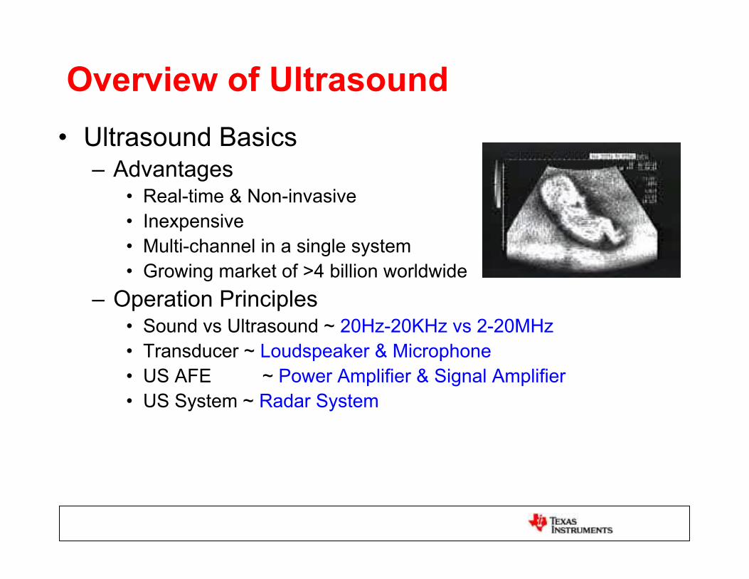
• Ultrasound Basics– Advantages
• Real-time & Non-invasive
• Inexpensive
• Multi-channel in a single system
• Growing market of >4 billion worldwide
– Operation Principles• Sound vs Ultrasound ~ 20Hz-20KHz vs 2-20MHz
• Transducer ~ Loudspeaker & Microphone
• US AFE ~ Power Amplifier & Signal Amplifier
• US System ~ Radar System
Overview of Ultrasound

• Ultrasound Basics
– Imaging Modes
• Brightness Mode (B-mode) 64-256 channels
• Doppler Mode (D-mode) 1-64 channels
• Color Doppler mode (2-D Doppler) 64-256 channels
• 3D & 4D Ultrasound 1024-4096 channels
Courtesy of GE
Ultrasound Basics

• Ultrasound Basics
– Growing Portable Ultrasound Market
• Ambulance, Emergency Room, Battle Field
– Demand of Advanced ICs
• Compact, Low Power, & Low Noise
– More Channels per System
– More Systems per Year
– Much More Opportunities for ICs
Courtesy of GE
Ultrasound Basics

t
PrinciplePrinciple

B-mode
The machine – Top level

Physics (I)
43.10-50.0013331Air
4-106.121.73600Compact bone
21.631.041568Muscle
0.51.420.971470Fat
Attenuation
[dB/MHz.cm]
Z = c
[105 Rayl][g/cm3]c [m/s]Substance
Imaging Systems for Medical Diagnostics - Siemens
PositionFrame rate
ReflectionsStrong or weak
Depth

Physics (II)
f.2.x. = 100dB= 1dB/(MHz.cm) cos.
2
w
r
f
cRLateral
f
cc
FBWR dBAxial
22.26
0.150.43.30.115
0.20.650.1610
0.351.2100.315
0.83250.782
Axial resolution
[mm]
Lateral resolution
[mm]
Penetration
depth [cm]
Wavelength
[mm]
Frequency
[MHz]
c = 1560m/s
Imaging Systems for Medical Diagnostics - Siemens

Frame rate
Example:
c = 1540m/s60o sector0.5o beam spacing25cm depth
120 beams25cm x 2 / 1540m/s =320us / beam
26 frames/s

Mechanical Scan
Courtesy of GE
Mechanical
Mechanical
Electrical

Electronic scan
Courtesy of Vermon
http://www.es.oersted.dtu.dk/staff/jaj/field/index.html
•Fast frame rate
•Low noise
•More patient friendly

Ultrasound System
Tx BufferAmp
ADC
DAC5652OPA695
VCA2615/7VCA8613/7
VCA8500/10
AFE5805/04/51/01 ADS527x/8x
ADS1605/06/25/26
ColorDoppler (PW)
Processing(F-Mode)
Image & Motion
Processing(B-Mode)
SpectralDoppler
Processing(D-Mode)
CW Analog Beam Former
Transducer
HV Mux/Demux
T/RSwitches
Transducer
Transducer
Transducer
Transducer
Transducer
Transducer
Transducer
TI Goal: More Colorful Diagram, ease of US design
TX734for TX
TX810

• Ultrasound Transmitter: Signal Generator
• Ultrasound T/R Switch: Protect LV RX
• Ultrasound Multiplexer: Reduce TX/RX CH#
Main Components in Ultrasound TX
HV TX
HV T/R
switchVCA
HV MUX
ADC
LV RX

• Ultrasound VCAs
– Amplify signals from 10uV~1V i.e.100dB
– Compensate attenuation in tissues
• Ultrasound ADCs
– Digitize conditioned signals
VCA
ADC
Main Components in Ultrasound RX

Tx beamformer
Transducer
array
1
2
A
3
4
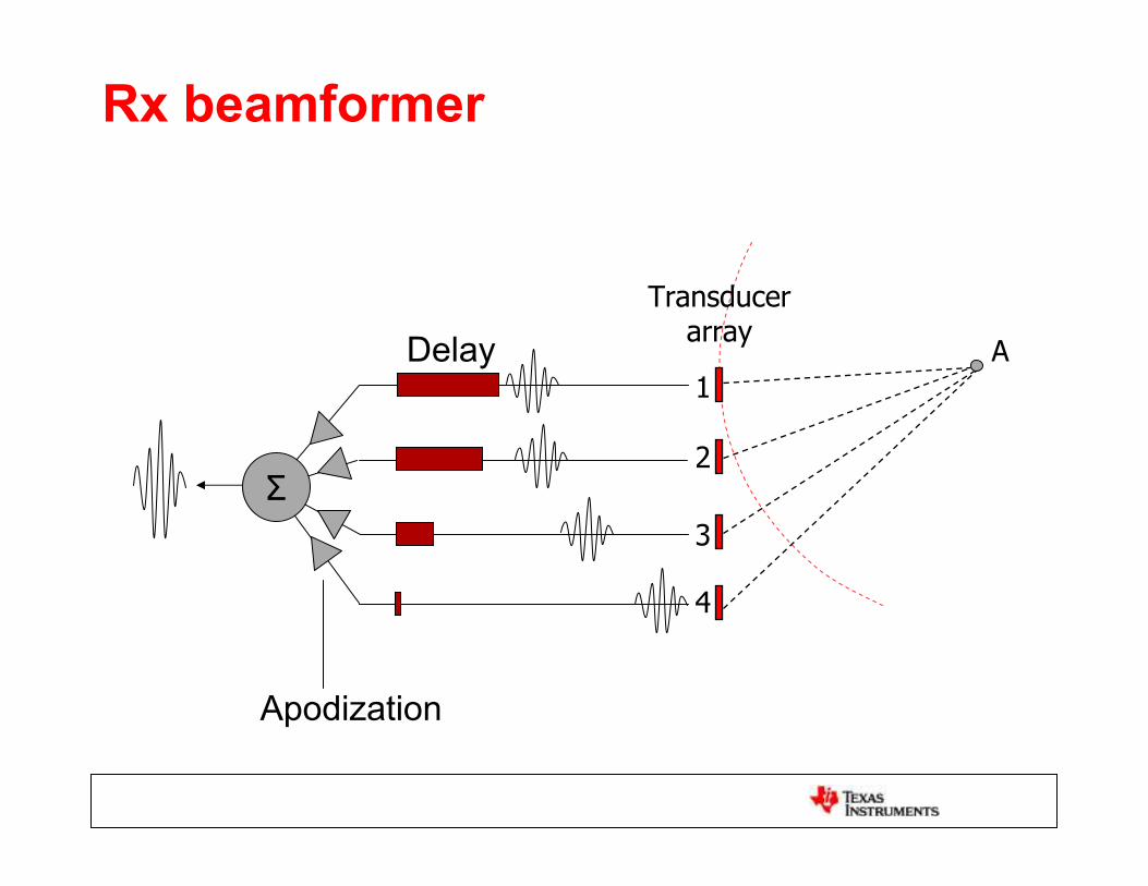
Rx beamformer
Transducer
array
1
2
A
3
4
Delay
Apodization

Receive Beamforming
Transducer
array
1
2
A1
3
4
B1 C1 Line1
Line 2
AD
Cs
4 3
2 1
5ns
A1
A2 B2 C2
ADCsamples Interpolated
ADC Sample Rate: 40MSPS 25ns intervalBF Resolution: < /16: 10MHz >160MSPS <5ns

Receiver Solutions for Ultrasound
512
1024+
SystemChannels
64 Portable
HighEnd
32
UltraPortable
128
256
MidRange
AFE5805
AFE580X
Future
Production
Sampling
AFE5804
AFE5801
AFE5851

Transmit Solutions for UltrasoundM
id
Ran
ge
Po
rtab
le
Ult
ra
Po
rtab
le
Platform/System
Hig
h
En
d
Production Sampling
FutureDevelopment
2008 2009 2010
TI Proprietary – Strictly Confidential
TX734Quad Output
+/- 90V3 Level
TX810
8 ChannelTR Switch
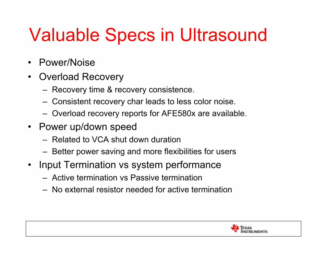
Valuable Specs in Ultrasound
• Power/Noise
• Overload Recovery
– Recovery time & recovery consistence.
– Consistent recovery char leads to less color noise.
– Overload recovery reports for AFE580x are available.
• Power up/down speed
– Related to VCA shut down duration
– Better power saving and more flexibilities for users
• Input Termination vs system performance
– Active termination vs Passive termination
– No external resistor needed for active termination

Valuable Specs in Ultrasound
• Matching among channels and chips
– Considered probe sensitivity variation
– Chip matching is a guaranteed number at ATE.
• Harmonic Distortion(HD2 and HD3)
– Harmonic Imaging (HD2)
– CW demodulation (HD3)
• Jitter vs Color Noise
• CW IQ Matching
– Affect the forward and backward flow detection
• SNR at low gain i.e. SNR at near and mid range
– Related to VCA IRN and PGA gain specs
Detail information can be obtained from TI MBU
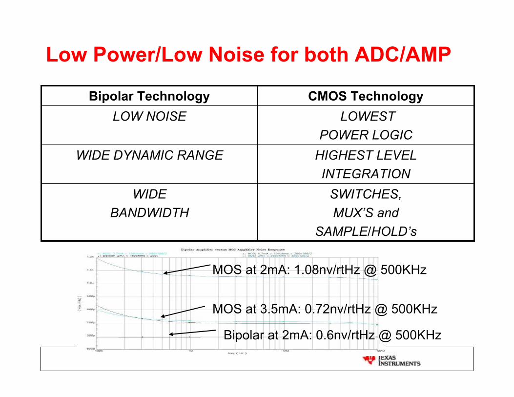
Low Power/Low Noise for both ADC/AMP
LOWEST
POWER LOGIC
LOW NOISE
SWITCHES,
MUX’S and
SAMPLE/HOLD’s
WIDE
BANDWIDTH
HIGHEST LEVEL
INTEGRATION
WIDE DYNAMIC RANGE
CMOS TechnologyBipolar Technology
MOS at 2mA: 1.08nv/rtHz @ 500KHz
Bipolar at 2mA: 0.6nv/rtHz @ 500KHz
MOS at 3.5mA: 0.72nv/rtHz @ 500KHz

Low Power/Low Noise for both ADC/AMP
ADS528x- C05
0.18um CMOSLow Power ADC
High Digital Intensity
VCA85xx –BiCom3X0.35um BiCOMS
Lowest Power 60mW/Ch
Highly Integrated (8 Ch)
Voltage-Controlled AMPBiCOM3x or
Future
BiCom
Process
Technology?
Low Power Low
Noise AFEsVCA ADC

Overload Recovery
• Signal Path & VCA Requirements
Transducer
SkinVessel
Near Field• Low TGC Gain setting• Large echo likely to
overload LNANeed: Fast overload
Recovery of LNA
Mid-far Field• Increasing/High TGC Gain setting• Potential overload of LNA and PGANeed: Fast and Repeatable overload
recovery characteristics
• Multiple Echoes closelyspaced together (wall,blood,wall) • Large difference in strength (40~60dB)
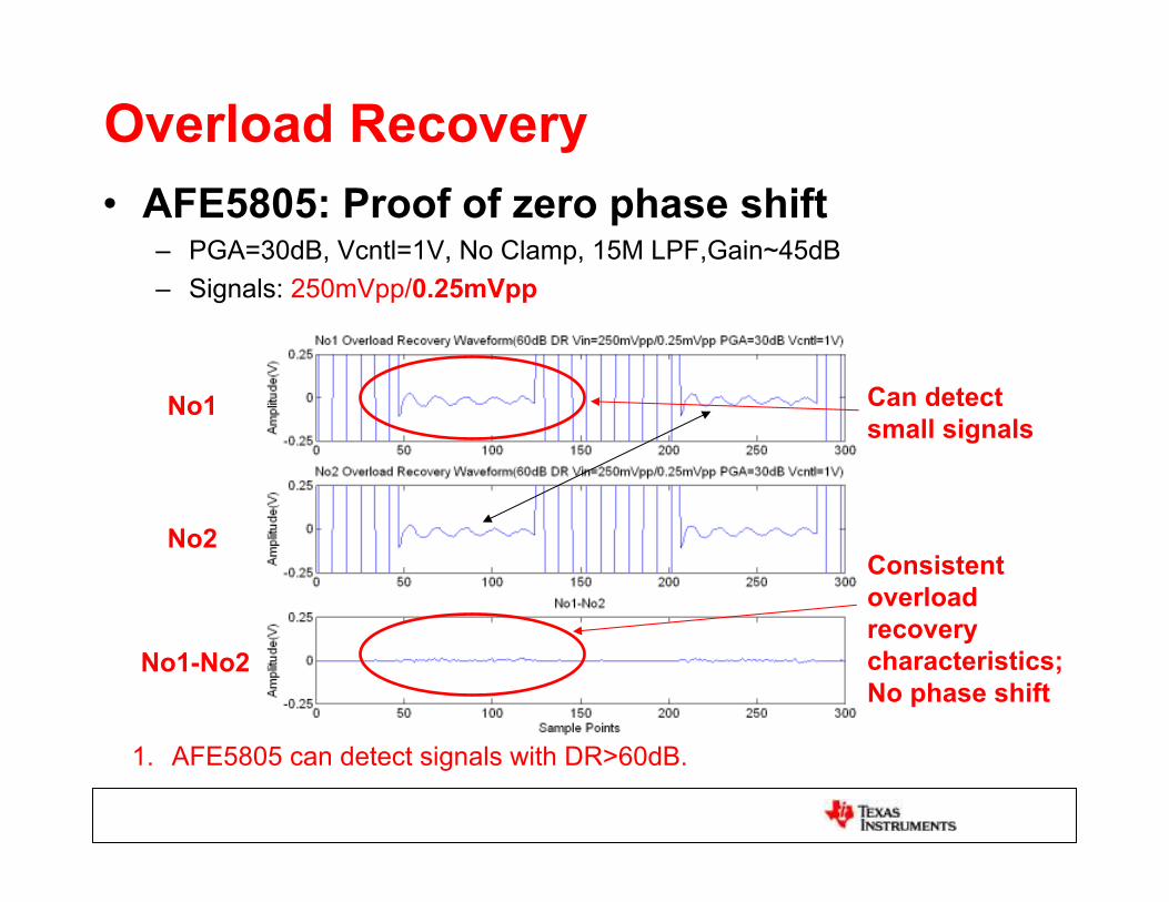
Overload Recovery
• AFE5805: Proof of zero phase shift– PGA=30dB, Vcntl=1V, No Clamp, 15M LPF,Gain~45dB
– Signals: 250mVpp/0.25mVpp
1. AFE5805 can detect signals with DR>60dB.
No1
No2
No1-No2
Can detect
small signals
Consistent
overload
recovery
characteristics;
No phase shift

Overload Recovery
• AFE5804: Proof of phase detection
180 Phase shift
No1
No2
No1-No2
1. The small signal amplitude in No1-No2 is doubled.
2. 180 phase detection can be proved by amplitude doubling.
3. AFE5804 achieves excellent performance even at low power mode.

Gain Matching & Range
Mid Gain
High Gain Low Gain

Termination for Ultrasound
• Termination Purpose– Ultrasound signal is a wide band signal Short pulse
– Resolution is depending on pulse length
– Reflection can affect system resolution
– Xducer/cable: 100ohm; Rin of AFE: 10K MismatchingReflection
– Termination Reduce reflection Improve Resolution
Reflection from mismatching
Ideal 0dB axial resolution
Degraded 0dB axial resolution due to mismatching
Courtesy of of Biosound Inc

Termination for Ultrasound
• Termination Resistor is NOT noiseless
• Thermal Noise is Added
• Low Impedance termination High Noise Figure
• Termination vs Noise Figure
– No Termination: Lowest NF
– Active Termination: Medium NF
– Passive Termination: Highest NF
• Active termination is common on new AFEs

Future Ultrasound Solution
• Lower Power
• Higher Integration
• Ultra-Portable system
• Ultrasound Systems in Walmart

Digital X-rays

Spectrum
~124eV
~124keV
~511keV
E= h.f = hc
h = 6.63e-34 J.s = 4.1e-15 eV.s
6-8um
30um
7500km
4km
384Mm
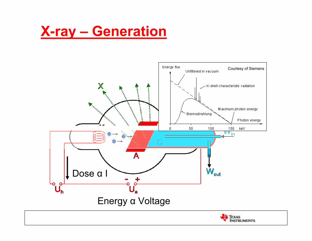
X-ray – Generation
Dose I
Energy Voltage
Courtesy of Siemens

X-ray Machine
Filter/collimatorAnti-scatter grid
DE
TE
CT
OR
ABSORBEDSCATTEREDTRANSMITTED

X-ray imagers overview
Courtesy of Hologic
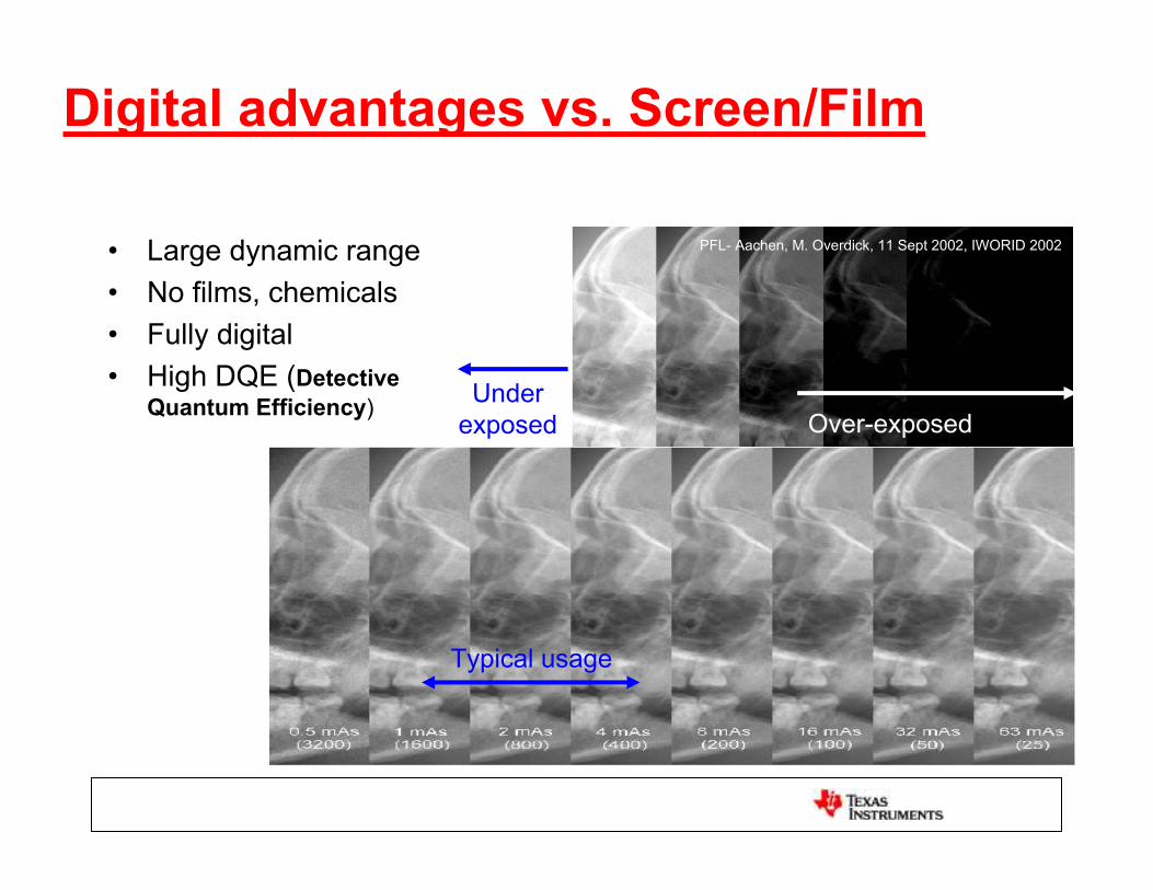
Digital advantages vs. Screen/Film
Over-exposedUnder
exposed
• Large dynamic range
• No films, chemicals
• Fully digital
• High DQE (Detective
Quantum Efficiency)
Typical usage
PFL- Aachen, M. Overdick, 11 Sept 2002, IWORID 2002

Direct
V

Indirect
Scintillator
AddressingReadout
ADC
PFL- Aachen, M. Overdick, 11 Sept 2002, IWORID 2002

AFE-XR0064 operation
1. CDS samples offset.2. The panel control turns on
the TFTs of a new column of pixels.
3. The charge is integrated (needs about 14us).
4. The CDS takes the integrated values and subtracts the offsets.
5. We can now RST the integrators. CDS still holds the analog values.
6. Analog values are muxed to the ADC inputs.

Readout time
Scan lines controlling gates of TFT:
• Ron 1-2M
• Cpixel 1-2pF
Example: 1536 * 1536 panel
Divide panel on 2 blocks of 768 columns,
each with 24 AFEXR0064:
768*27.8us = 21.35ms FR >30fps
For 128 lines (1 pixel/line):Tmin = 27.8us
130mW
142mW
142mW

Computer Tomography (CT)

The machine
3 revolutions per
second
1000 profiles per
revolution
3KSPS/pixel

Imaging the heart - Challenges
• @ 60bpm 1 beat/s.• Need 100ms shot at least to resolve 1mm
in diastole (when heart is more still)• Faster shot for other phases of the heart
or better resolution (for plaque, smaller arteries…)
• 12cm long.• Image the heart in one breath hold.• Varying beats: % case with stable heart
beat (courtesy of GE): • 4 beat: 97%• 5 beat: 92%• 8 beat: 39%• 10 beat: 10%
GE
1s100ms
P Q S T
R

Imaging the heart - Technique
ECG synchronization

Switched Integrator
Photodiode
Current
A-
+
CINT
B-
+
CINT
ADC
20bits
6KSPS (x2)
7mW/channel
FS 100’s pC
DDC232

Medical Imaging Safety

Radiation
Natural background: 2.4mSv/yearAir travel crew: 3mSv/year Radiation worker federal limit: 50mSv/yearDental radiography: 0.01mSvChest radiography: 0.1mSvMammography: 0.7mSvPET/SPECT : 7mSv Chess CT: 8mSvPelvic/abdomen CT: 10mSvCT Angiography: 15mSv50% of cases die in 30 days: 3Sv

Thank You!!!Comments & Questions
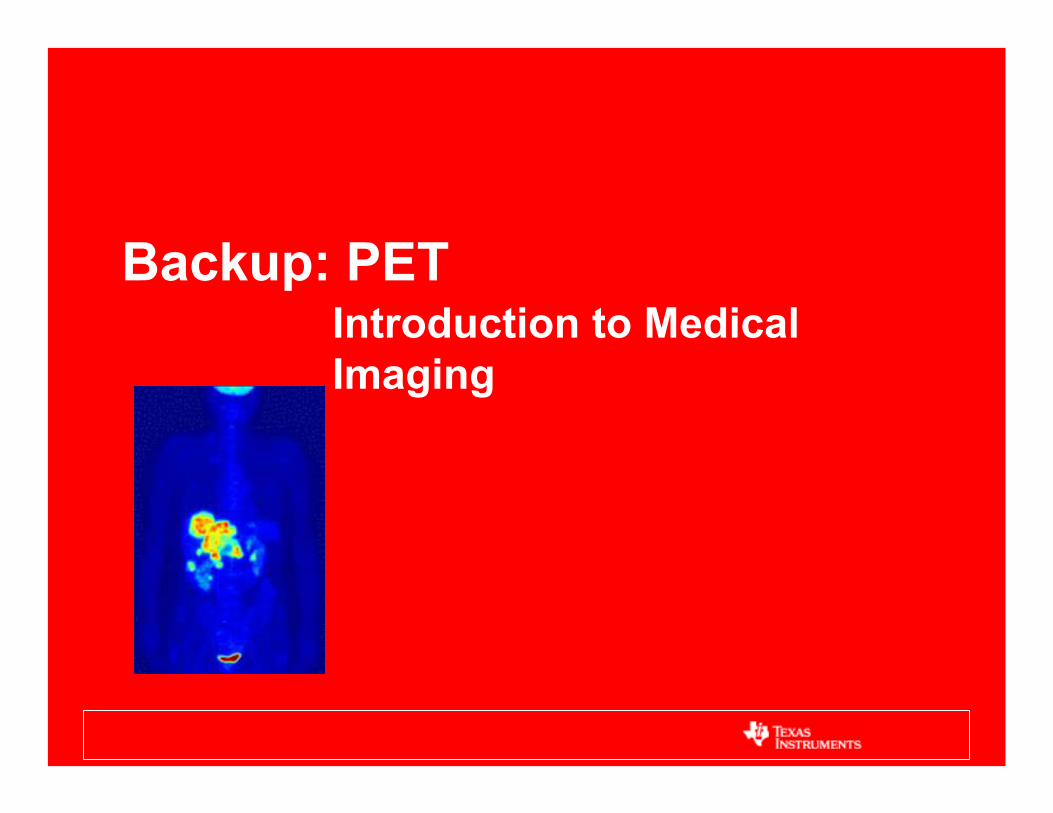
Backup: PET Introduction to Medical
Imaging
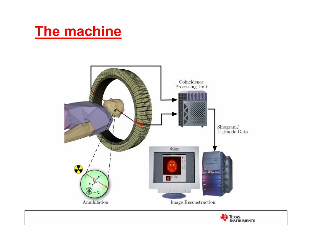
The machine

The detector
I
Example (from Derenzo): NaI(TI) - 3.3 cm Light output: 50k (38k?) photons/MeVPrincipal Decay time: 230 nsIndex of refraction: 1.85 15000 photons at
photocathode
3000 photoelectronsat first dynode
3.109 electrons at anode

Centroid
To ADCsPosition
Anger logic
i
mi
i
mii
E
Ex
mX
1
2
3
4
1 2 3 4
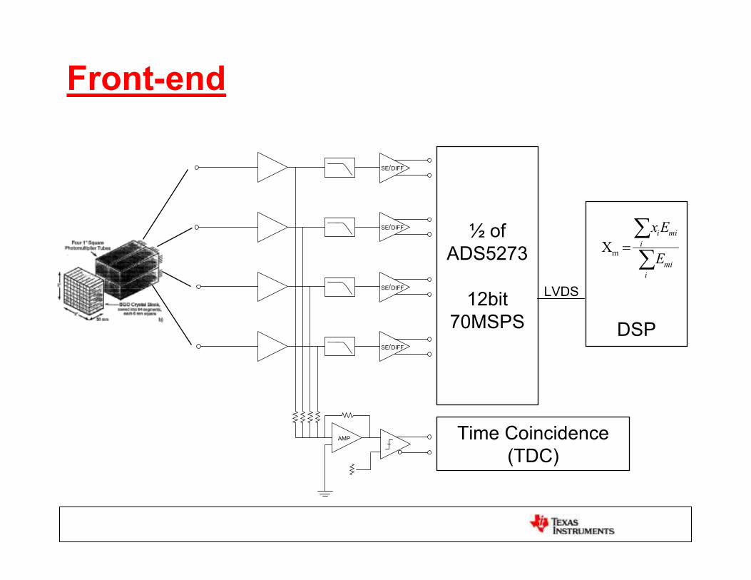
Front-end
AMP
SE DIFF
SE DIFF
SE DIFF
SE DIFF
Time Coincidence(TDC)
i
mi
i
mii
E
Ex
mX½ of
ADS5273
12bit70MSPS DSP
LVDS


