Introduction1-1 Part of slides provided by J.F Kurose and K.W. Ross, All Rights Reserved Chapter 1...
49
Introduction 1-1 Part of slides provided by J.F Kurose and K.W. Ross, All Rights Reserved Chapter 1 Computer Networks and the Internet Computer networking - A top-down approach featuring the internet 4th Edition, 2008 Addison Wesley James F. Kurose, Keith W. Ross ISBN 0-321-49770-8 Communication Networks P. Demeester
-
Upload
richard-singleton -
Category
Documents
-
view
247 -
download
0
Transcript of Introduction1-1 Part of slides provided by J.F Kurose and K.W. Ross, All Rights Reserved Chapter 1...

Introduction 1-1
Part of slides provided by J.F Kurose and K.W. Ross, All Rights Reserved
Chapter 1Computer Networksand the Internet
Computer networking -A top-down approach featuring the internet4th Edition, 2008Addison WesleyJames F. Kurose, Keith W. RossISBN 0-321-49770-8
Communication NetworksP. Demeester

Introduction 1-2
Chapter 1: Introduction
Our goal: Introduction to computer networks Limit to >80% of the technologies used
today Technologies : TCP+UDP, IP, Ethernet Describe applications (file transfer, e-mail ,
Web access,…)

Introduction 1-3
Chapter 1 outline
1.1 What is the Internet?[1.2 Network edge][1.3 Network core][1.4 Network access and physical media]1.5 Internet structure and ISPs[1.6 Delay & loss in packet-switched
networks]1.7 Protocol layers, service models[1.8 History]

Introduction 1-4
Move towards all-IP
VoIP Skype Video over IP Belgacom TV Internet of Things Smart environments
Operators are transforming their network towards all IP

Introduction 1-5
BT's 21st Century Network : current network
IP
ATM
PSTN
DSL
KStream
PSTNDPCN
PDH
Fibre
Copper
DWSS
ASDH
EndUser
~5knodes
~2knodes
~400nodes
~100nodes
~15nodes
MSH -SDH
~1knodes
Mesh -SDH
Inter-node transmission provided by
SDH/PDH platforms
CWSS
Today: multiple services
on multiple platforms
Other Networks

Introduction 1-6
BT's 21st Century Network : Future
IP-MPLS-WDMDSL
Fibre &Copper
Copper
Agg Box
EndUser
~5knodes
~100nodes
Class 5 Call Server
GFP on SDH
Content
WWW
ISPPSTN services migrate to IP
Other Networks
access aggregation core

Introduction 1-7
ISP
What’s the Internet: “nuts and bolts” view
router workstation
servermobile
ISP : Internet Service Provider
• How to address the terminals ?• How to find them ?• How to route the information ?• …

Introduction 1-11
The network edge
end systems (hosts): run application programs e.g. Web, email at “edge of network”
client/server model client host requests / receives
service from always-on server e.g. Web browser/server;
email client/server
peer-peer model: minimal (or no) use of
dedicated servers e.g. Gnutella, KaZaA

Introduction 1-12
The network core
mesh of interconnected routers
the fundamental question: how is data transferred through net? circuit switching:
dedicated circuit per call: telephone net
packet-switching: data sent thru net in discrete “chunks”

Introduction 1-13
Q: How to connect end systems to edge router?
residential access nets institutional access
networks (school, company)
mobile access networks
Keep in mind: bandwidth (bits per
second) of access network?
shared or dedicated?
Access networks and physical media

Introduction 1-14
Network taxonomy
Telecommunicationnetworks
FDM TDMNetworkswith VCs
DatagramNetworks
Circuit-switchednetworks
Packet-switchednetworks
Internet provides both connection-oriented (TCP) and connectionless services (UDP) to apps.

Introduction 1-15
Chapter 1 outline
1.1 What is the Internet?1.2 Network edge1.3 Network core1.4 Network access and physical media1.5 Internet structure and ISPs1.6 Delay & loss in packet-switched
networks1.7 Protocol layers, service models1.8 History
Introduction 1-16
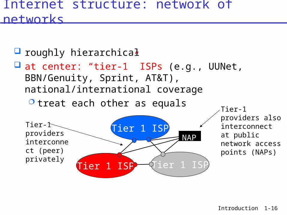
roughly hierarchical at center: “tier-1” ISPs (e.g., UUNet, BBN/Genuity,
Sprint, AT&T), national/international coverage treat each other as equals
Tier 1 ISP
Tier 1 ISP
Tier 1 ISP
Tier-1 providers interconnect (peer) privately
NAP
Tier-1 providers also interconnect at public network access points (NAPs)
Internet structure: network of networks
Introduction 1-17
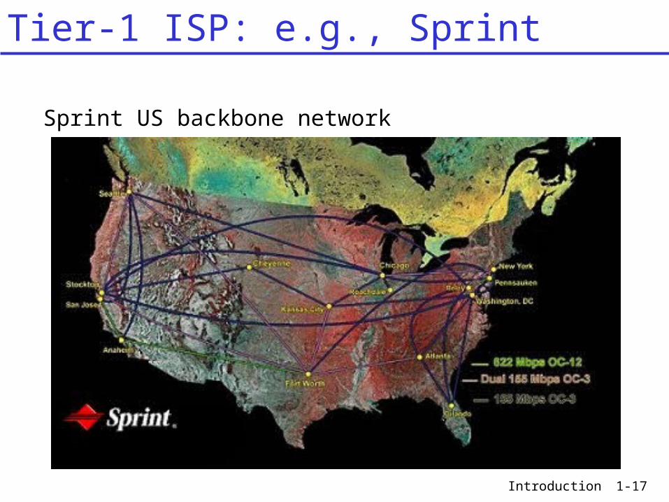
Tier-1 ISP: e.g., Sprint
Sprint US backbone network

Introduction 1-18
“Tier-2” ISPs: smaller (often regional) ISPs Connect to one or more tier-1 ISPs, possibly other tier-2 ISPs
Tier 1 ISP
Tier 1 ISP
Tier 1 ISP
NAP
Tier-2 ISPTier-2 ISP
Tier-2 ISP Tier-2 ISP
Tier-2 ISP
- Tier-2 ISP pays tier-1 ISP for connectivity to rest of Internet- Tier-2 ISP is customer oftier-1 provider
Tier-2 ISPs also peer privately with each other, interconnect at NAP
Internet structure: network of networks

Introduction 1-19
“Tier-3” ISPs and local ISPs last hop (“access”) network (closest to end systems)
Tier 1 ISP
Tier 1 ISP
Tier 1 ISP
NAP
Tier-2 ISPTier-2 ISP
Tier-2 ISP Tier-2 ISP
Tier-2 ISP
localISPlocal
ISPlocalISP
localISP
localISP Tier 3
ISP
localISP
localISP
localISP
Local and tier- 3 ISPs are customers ofhigher tier ISPsconnecting them to rest of Internet
Internet structure: network of networks

Introduction 1-20
a packet passes through many networks!
Tier 1 ISP
Tier 1 ISP
Tier 1 ISP
NAP
Tier-2 ISPTier-2 ISP
Tier-2 ISP Tier-2 ISP
Tier-2 ISP
localISPlocal
ISPlocalISP
localISP
localISP Tier 3
ISP
localISP
localISP
localISP
Internet structure: network of networks

Introduction 1-21
Routers in the Internet : Global
In 2005 the number of (pubic) routers is in the 100.000 - 200.000 range. The average number of hops a packet has to cross is in the order of 13.

Introduction 1-22
Routers in the Internet : Zoom-In

Introduction 1-23
Routers in the Internet : Global
www.cybergeography.org/atlas/geographic.html
NSFNET1992

Introduction 1-24
Routers in the Internet : Global
2001

Introduction 1-25
Routers in the Internet : Global
2000

Introduction 1-26
Chapter 1 outline
1.1 What is the Internet?1.2 Network edge1.3 Network core1.4 Network access and physical media1.5 Internet structure and ISPs1.6 Delay & loss in packet-switched
networks1.7 Protocol layers, service models1.8 History

Introduction 1-27
Protocol “Layers”
Networks are complex!
many “pieces”: hosts routers links of various
media applications protocols hardware,
software
Question: Is there any hope of
organizing the structure of a network?
Or at least in our discussion of networks?

Introduction 1-28
An example : postal services
writer friend“application” service : friend reads book
they agree and make a “connection”
they use the unreliablepostal services “network”

Introduction 1-29
client server
An example : web access
Internet Protocol
10 Mbit/s local area network
RFC 1011 : “Internet Protocols”
router
TCP-Connection
100 Gbit/s WDM transatlantic optical cable
2 Mbit/sISDN linklocal telephone
switch
56.6 kbit/smodem connection
140 Mbit/sPDH link
URL: www.ietf.org
IETF webpage
IP-datagram
find info about Internet on the Web !

Introduction 1-30
What’s a protocol ?
human protocols: “what’s the time?” “I have a question” introductions
… specific msgs sent… specific actions
taken when msgs received, or other events
network protocols: machines rather than
humans all communication
activity in Internet governed by protocols
protocols define format, order of msgs sent and
received among network entities, and actions taken on msg
transmission, reception

Introduction 1-31
What’s a protocol ?
a human protocol and a computer network protocol:
Hi
Hi
Got thetime?
2:00
TCP connection req
TCP connectionresponse
Get http://www.awl.com/kurose-ross
<file>
time

Introduction 1-32
Why layering ?
Dealing with complex systems: explicit structure allows identification of functions,
relationship between complex system’s possible layered reference model
modularization eases maintenance and updating of system change of implementation of layer’s service is
transparent to rest of system e.g., change in postal service implementation
doesn’t affect rest of system (as long as interfaces are the same)
Introduction 1-33
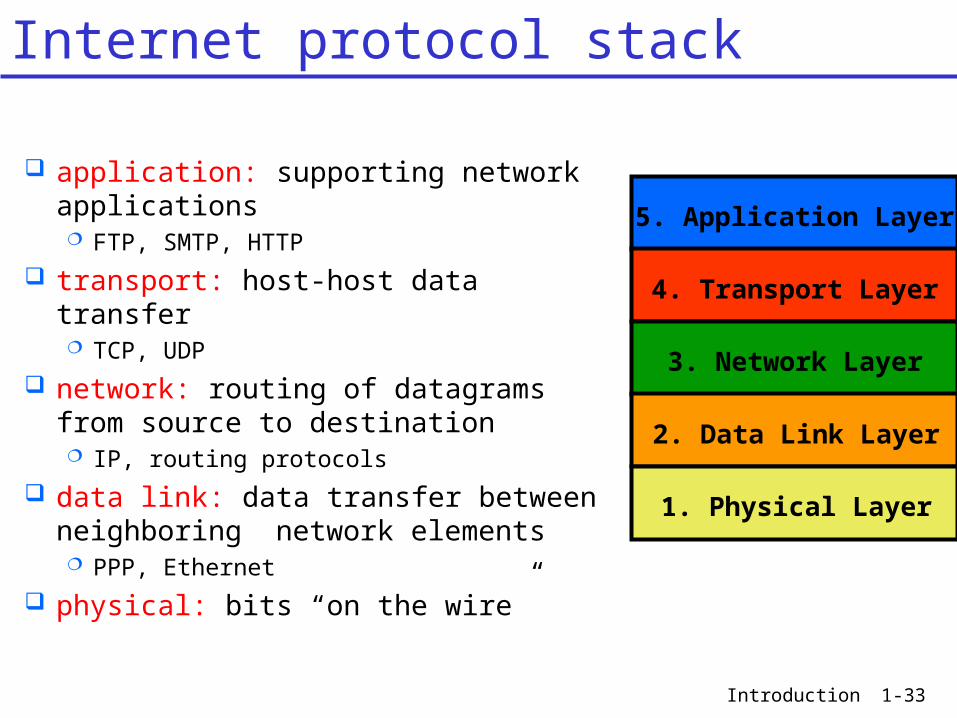
Internet protocol stack
application: supporting network applications FTP, SMTP, HTTP
transport: host-host data transfer TCP, UDP
network: routing of datagrams from source to destination IP, routing protocols
data link: data transfer between neighboring network elements PPP, Ethernet
physical: bits “on the wire”
5. Application Layer
4. Transport Layer
3. Network Layer
2. Data Link Layer
1. Physical Layer

Introduction 1-34
Each layer: distributed “entities”
implement layer functions in the node
entities perform actions, exchange messages with peers
applicationtransportnetworkdata linkphysical
applicationtransportnetworkdata linkphysical
applicationtransportnetworkdata linkphysical
applicationtransportnetworkdata linkphysical
networkdata link data linkphysical physical
Layering: logical communication

Introduction 1-35
E.g.: transport take data from
application layer add addressing,
reliability check, info to form “segment”
send segment to peer
wait for peer to ack receip
applicationtransportnetworkdata linkphysical
applicationtransportnetworkdata linkphysical
applicationtransportnetworkdata linkphysical
applicationtransportnetworkdata linkphysical
networkdata link data linkphysical physical
data
data
Layering: logical communication

Introduction 1-36
applicationtransportnetworkdata linkphysical
applicationtransportnetworkdata linkphysical
applicationtransportnetworkdata linkphysical
applicationtransportnetworkdata linkphysical
networkdata link data linkphysical physical
data
data
Layering: “physical” communication

Introduction 1-37
Application Layer : File Transfer Protocol
OPENconnection
TCP control connection
Login, password OK Request directory
TCP transfer connection
directory
TCP transfer connection
file transfer
CLOSEconnection
FTPserver
Request file transfer

Introduction 1-38
Login, passwordOK
read directorydirectory
Request file transferfile transfer
application layer : FTP
transport layer : TCP
client layerFTP-server
“peer to peer” communication
server layer
Remark : client - server
SAP SAP
SAP : Service Access point
Application/Transport Layer

Introduction 1-39
Transmission Control Protocol
TCP connection
connection oriented (virtual connection in software of terminals : state)
3-way handshake protocol point to point, full duplex exchange of segments (=unit of data)
(during a file transfer the file will be cut in pieces : segments) reliable transport (=acknowledgement, retransmission, timers, …) flow control (sender won’t overwhelm receiver) congestion control
(senders “slow down sending rate” when network congested) segments are sent over a network of routers in the IP layer typically used for http, ftp, smtp, pop, …

Introduction 1-40
<SYN_C>
<ACK of SYN_C,SYN_S>
<ACK of SYN_S>3-w
ay h
an
dsh
ake
If set-up segment is lost==> time-outs
Client side Server side
Setup TCP connection
pro
gre
ssin
g t
ime
SYN : SYNchronizationACK : ACKnowledgment
C : Client sideS : Server side
TCP connection setup

Introduction 1-41
TCP for file transfer
<SYN_S>
<ACK of SYN_S,SYN_C>
<ACK of SYN_C>
<bytes 1-1000>
<ACK bytes 1-1000 >
<bytes 1001-2000>
<ACK bytes 1001-2000 >
<bytes 2001-3000>
<ACK bytes 2001-3000 >
<bytes 2001-3000>
time-out
<ACK bytes 3001-4000 >
<bytes 3001-4000>
0001-1000
1001-2000
2001-3000
3001-4000
4001-5000
0001-1000
1001-2000
2001-3000
3001-4000
4001-5000
TCP connection for file transfer
Introduction 1-42
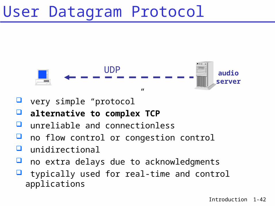
User Datagram Protocol
UDP audioserver
very simple “protocol” alternative to complex TCP unreliable and connectionless no flow control or congestion control unidirectional no extra delays due to acknowledgments typically used for real-time and control applications

Introduction 1-43
UDP real time audio
<bytes 1-1000>
<bytes 1001-2000>
<bytes 2001-3000>
<bytes 3001-4000>
<bytes 4001-5000>
• send as quick as possible• no extra delay due to acknowledgment• no retransmissions
0001-1000
1001-2000
2001-3000
3001-4000
4001-5000
0001-1000
1001-2000
2001-3000
3001-4000
4001-5000
UDP for real time audio transfer

Introduction 1-44
network layer : IP
Transport/Network Layer
server layer
transport layer : TCP
client layer
TCP connection
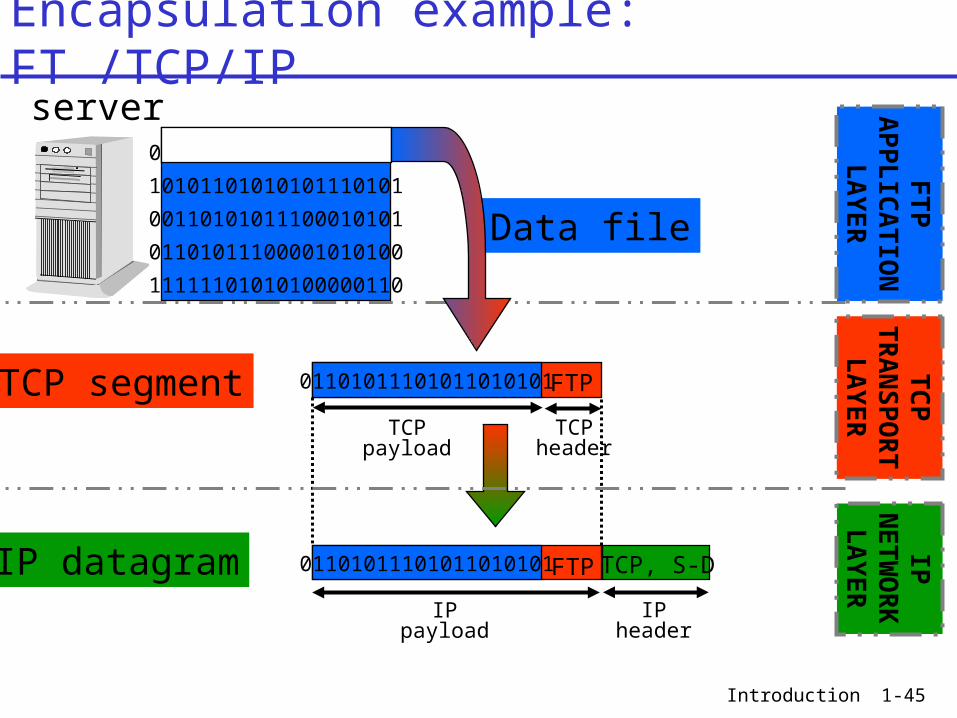
SERVICE : Transfer TCP segment from source to destination SOLUTION : Encapsulate TCP segment in IP datagram (destination indicated !).IP network layer will transfer IP datagram over links and routers to destination.
router
link
IP datagrams
Introduction 1-45
01101011101011010101
10101101010101110101
00110101011100010101
01101011100001010100
11111101010100000110
server
Data file
Encapsulation example: FT /TCP/IP
IP datagram
TCP segment
TCP, S-D
IPheader
IPpayload
TCPpayload
FTP
TCPheader
01101011101011010101FTP
IPN
ETW
OR
KLA
YER
TC
PTR
AN
SP
OR
TLA
YER
FTP
AP
PLIC
ATIO
NLA
YER
01101011101011010101

Introduction 1-46
A B
C
D
E
Y:to BZ:to D
Y:to CZ:to E
Y:to Y
Source:XDestination:YContent:TCP
Storeand
Forward
RoutingTable
Buffer
Router
Link
computerhost
terminal
W
X
Y
Z
Network Layer : Internet Protocol

Introduction 1-47
Unidirectional Datagram (“packet”) based store and forward Connectionless Flexibility is provided by network elements (routers) Best effort : no guarantee on delay, delivery, …
(no Quality of Service : QoS) IP layer is the server layer of the TCP layer
and the client layer of the Data Link Layer
Network Layer : Internet Protocol
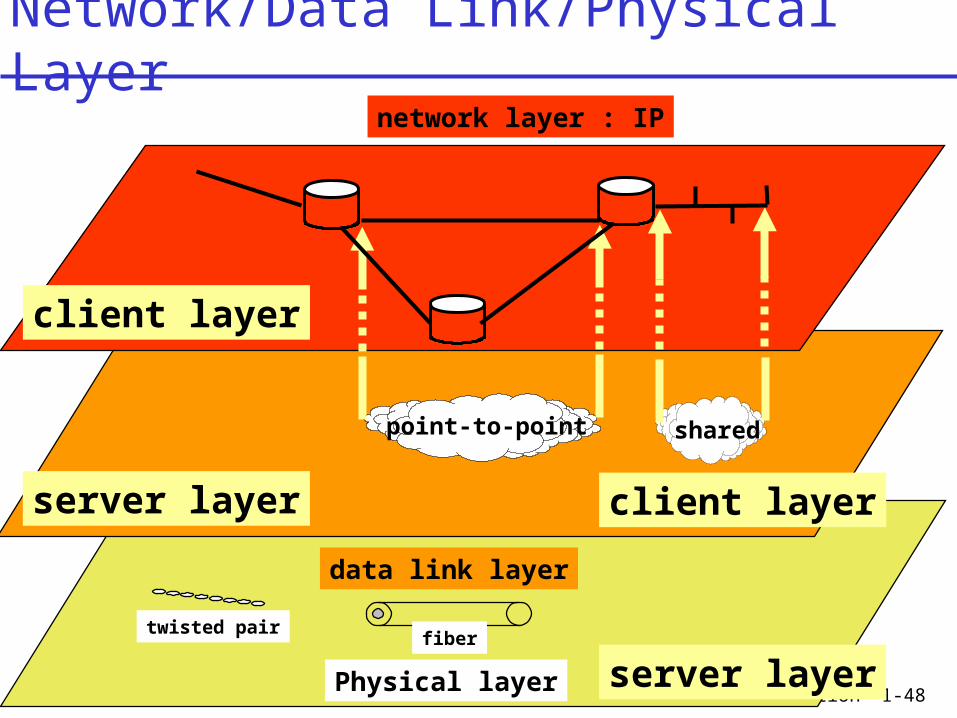
Introduction 1-48Physical layer
data link layer
server layer
network layer : IP
client layer
point-to-point shared
twisted pairfiber
server layer
client layer
Network/Data Link/Physical Layer

Introduction 1-49
Data Link Layer
point-to-point example : PPP protocol (Point-to-Point Protocol) establish a connection between two routers or a router
and a terminal can use e.g. an SDH VC-4 150 Mbit/s connection
between 2 routers or a telephone ISDN connection of 64 kbit/s between a terminal at home and the access router of an ISP.
shared medium example : Ethernet MAC : CSMA/CD
Les 1-2
Introduction 1-50
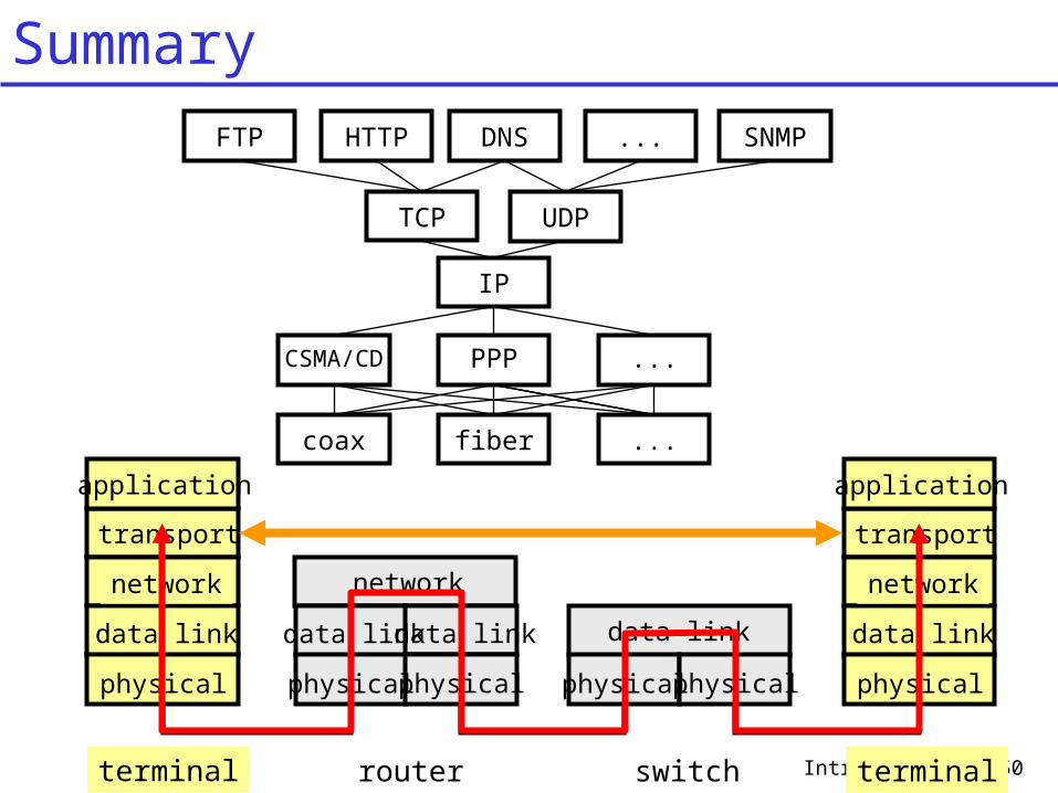
transport
application
network
data link
physical
terminal
network
data link
physical
data link
physical
router
data link
physicalphysical
switch
transport
application
network
data link
physical
terminal
IP
FTP HTTP DNS ... SNMP
TCP UDP
PPP ...CSMA/CD
fiber ...coax
Summary

Introduction 1-51
FTP20,21
HTTP80
DNS53
... SNMP161,162
TCP6
UDP17
Identification : Application : port number
FTP port 20 (data), 21 (control)TCP or UDP : protocol number
TCP : 6 UDP : 17
Host : IP address (e.g. 157.193.122.1)
Note : some terminology : Application : messageTransport : segment Network : datagram (or packet)Data Link : frame
IP157.193.
122.1
Summary

Introduction 1-52
Table of contents
1.1 What is the Internet? 3 1.5 Internet structure and ISPs 15 1.7 Protocol layers, service models 26 Summary 50 Table of contents 52