Introduction1-1 COMP 561 Computer Networks Fall 2005.
71
Introduction 1-1 COMP 561 Computer Networks Fall 2005
-
date post
22-Dec-2015 -
Category
Documents
-
view
221 -
download
3
Transcript of Introduction1-1 COMP 561 Computer Networks Fall 2005.
Introduction 1-1
COMP 561
Computer Networks
Fall 2005

Introduction 1-2
Introduction: course description & calendar
Answers to frequently asked questions
Prerequisites
Overview

Introduction 1-3
Who’s Who Instructors:
Dr. Liu, Yunhao Email: [email protected] Office: Room 3548 Phone: 2358-7019
Course web site http://www.cs.ust.hk/~liu/comp561/index.htm

Introduction 1-4
Topics Computer Networks and the Internet Application Layer Transport Layer Network Layer and Routing Link Layer and Local Area Networks Multimedia Networking Internet Security Peer-to-peer and grid computing Sensor network Mobile Computing
Introduction 1-5
Grading
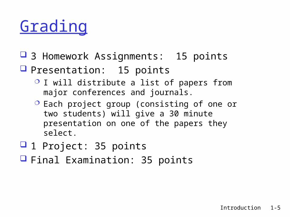
3 Homework Assignments: 15 points Presentation: 15 points
I will distribute a list of papers from major conferences and journals.
Each project group (consisting of one or two students) will give a 30 minute presentation on one of the papers they select.
1 Project: 35 points Final Examination: 35 points

Introduction 1-6
Conduct in the Classroom
1. Please try to be on-time to class.
When you come in late, you disrupt your class. As a general rule, if you are more than 10 minutes late, you should not enter the classroom. If you arrive late, but need to see the instructor or pick up lecture notes, please return at the end of the class period.
Introduction 1-7
2. Please do not talk while in class except to raise questions.
Conduct in the Classroom
You should not do things during class that disrupt the class or distract your classmates. If you have a pager or cellular phone, turn if off when you are in class.
And please pay attention to the signs that tell you not to eat or drink in the classrooms.
Introduction 1-8
3. Cheating will be punished.
Conduct in the Classroom
You should not copy assignments, projects, or allow your work to be copied by others. Cheating in exams are forbidden. Each must do his/her own work.
You will get zero mark for the work if caught cheating for the first time. For the second time, you will FAIL the course and be reported to the University Disciplinary Committee for further action.

Introduction 1-9
You are investing several years of your life in your university education.
Learning to accept responsibility is an important part of that education.
The classroom is a good place to begin
showing that you are ready for the
responsibilities of being an adult.
Conduct in the Classroom

Introduction 1-10
Comp 561: Introduction

Introduction 1-11
Chapter 1: Introduction
Our goal: get “feel” and
terminology more depth, detail
later in course approach:
use Internet as example
Overview: what’s the Internet what’s a protocol? network edge network core access net, physical media Internet/ISP structure performance: loss, delay protocol layers, service
models network modeling

Introduction 1-12
Chapter 1: roadmap
1.1 What is the Internet?1.2 Network edge1.3 Network core1.4 Network access and physical media1.5 Internet structure and ISPs1.6 Delay & loss in packet-switched
networks1.7 Protocol layers, service models1.8 History

Introduction 1-13
What’s the Internet: “nuts and bolts” view
millions of connected computing devices: hosts = end systems
running network apps communication links
fiber, copper, radio, satellite
transmission rate = bandwidth
routers: forward packets (chunks of data)
local ISP
companynetwork
regional ISP
router workstation
servermobile

Introduction 1-14
What’s the Internet: “nuts and bolts” view protocols control sending,
receiving of msgs e.g., TCP, IP, HTTP, FTP,
PPP
Internet: “network of networks” loosely hierarchical public Internet versus
private intranet
Internet standards RFC: Request for comments IETF: Internet Engineering
Task Force
local ISP
companynetwork
regional ISP
router workstation
servermobile

Introduction 1-15
What’s the Internet: a service view communication
infrastructure enables distributed applications: Web, email, games, e-
commerce, file sharing
communication services provided to apps: Connectionless unreliable connection-oriented
reliable
Introduction 1-16
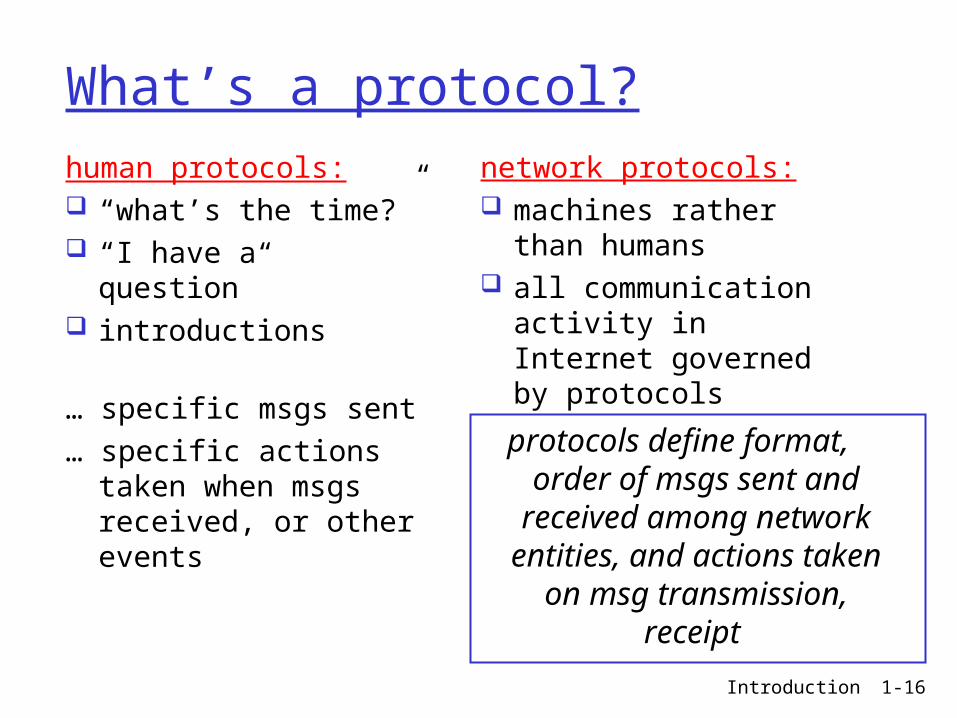
What’s a protocol?human protocols: “what’s the time?” “I have a question” introductions
… specific msgs sent… specific actions
taken when msgs received, or other events
network protocols: machines rather than
humans all communication
activity in Internet governed by protocols
protocols define format, order of msgs sent and
received among network entities, and actions taken on msg transmission, receipt
Introduction 1-17
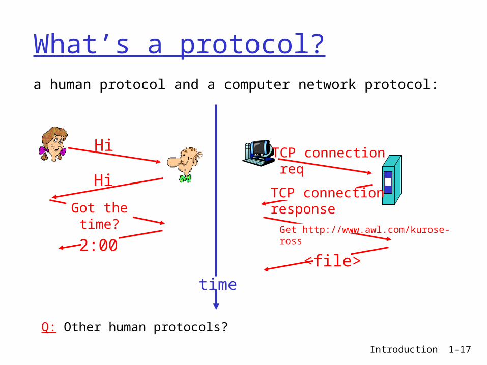
What’s a protocol?a human protocol and a computer network protocol:
Q: Other human protocols?
Hi
Hi
Got thetime?
2:00
TCP connection req
TCP connectionresponseGet http://www.awl.com/kurose-ross
<file>time
Introduction 1-18
Chapter 1: roadmap
1.1 What is the Internet?1.2 Network edge1.3 Network core1.4 Network access and physical media1.5 Internet structure and ISPs 1.6 Delay & loss in packet-switched
networks1.7 Protocol layers, service models1.8 History

Introduction 1-19
A closer look at network structure: network edge:
applications and hosts network core:
routers network of networks
access networks, physical media: communication links

Introduction 1-20
The network edge: end systems (hosts):
run application programs e.g. Web, email at “edge of network”
client/server model client host requests, receives
service from always-on server e.g. Web browser/server;
email client/server
peer-peer model: minimal (or no) use of
dedicated servers e.g. Gnutella, KaZaA

Introduction 1-21
Network edge: connection-oriented service
Goal: data transfer between end systems
handshaking: setup (prepare for) data transfer ahead of time Hello, hello back
human protocol set up “state” in two
communicating hosts
TCP - Transmission Control Protocol Internet’s connection-
oriented service
TCP service [RFC 793] reliable, in-order byte-
stream data transfer loss: acknowledgements
and retransmissions
flow control: sender won’t overwhelm
receiver
congestion control: senders “slow down
sending rate” when network congested
Introduction 1-22
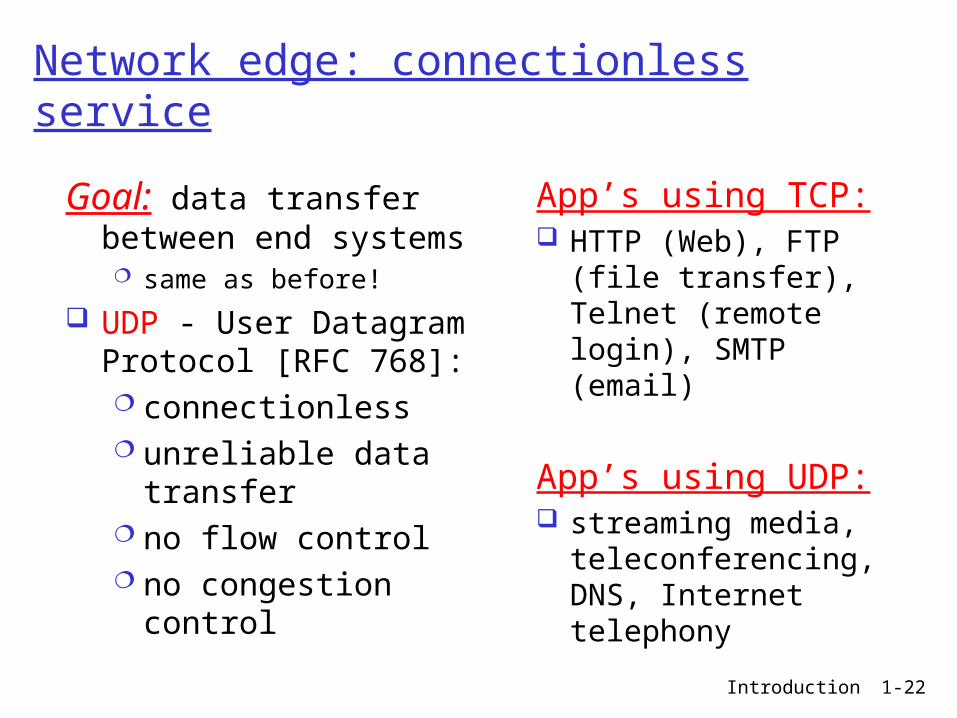
Network edge: connectionless service
Goal: data transfer between end systems same as before!
UDP - User Datagram Protocol [RFC 768]: connectionless unreliable data
transfer no flow control no congestion
control
App’s using TCP: HTTP (Web), FTP (file
transfer), Telnet (remote login), SMTP (email)
App’s using UDP: streaming media,
teleconferencing, DNS, Internet telephony
Introduction 1-23
Chapter 1: roadmap
1.1 What is the Internet?1.2 Network edge1.3 Network core1.4 Network access and physical media1.5 Internet structure and ISPs 1.6 Delay & loss in packet-switched
networks1.7 Protocol layers, service models1.8 History

Introduction 1-24
The Network Core
mesh of interconnected routers
the fundamental question: how is data transferred through net? circuit switching:
dedicated circuit per call: telephone net
packet-switching: data sent thru net in discrete “chunks”

Introduction 1-25
Network Core: Circuit Switching
End-end resources reserved for “call”
link bandwidth, switch capacity
dedicated resources: no sharing
circuit-like (guaranteed) performance
call setup required

Introduction 1-26
Network Core: Circuit Switching
network resources (e.g., bandwidth) divided into “pieces”
pieces allocated to calls
resource piece idle if not used by owning call (no sharing)
dividing link bandwidth into “pieces” frequency division time division

Introduction 1-27
Circuit Switching: FDM and TDM
FDM
frequency
time
TDM
frequency
time
4 users
Example:

Introduction 1-28
Network Core: Packet Switching
each end-end data stream divided into packets
user A, B packets share network resources
each packet uses full link bandwidth
resources used as needed
resource contention: aggregate resource
demand can exceed amount available
congestion: packets queue, wait for link use
store and forward: packets move one hop at a time Node receives complete
packet before forwarding
Bandwidth division into “pieces”Dedicated allocationResource reservation

Introduction 1-29
Packet switching versus circuit switching
1 Mb/s link each user:
100 kb/s when “active”
active 10% of time
circuit-switching: 10 users
packet switching: with 35 users,
probability > 10 active less than .0004
Packet switching allows more users to use network!
N users
1 Mbps link

Introduction 1-30
Network Taxonomy
Telecommunicationnetworks
Circuit-switchednetworks
FDM TDM
Packet-switchednetworks
Networkswith VCs
DatagramNetworks
• Datagram network is not either connection-oriented or connectionless.• Internet provides both connection-oriented (TCP) and connectionless services (UDP) to apps.

Introduction 1-31
Chapter 1: roadmap
1.1 What is the Internet?1.2 Network edge1.3 Network core1.4 Network access and physical media1.5 Internet structure and ISPs 1.6 Delay & loss in packet-switched
networks1.7 Protocol layers, service models1.8 History
Introduction 1-32
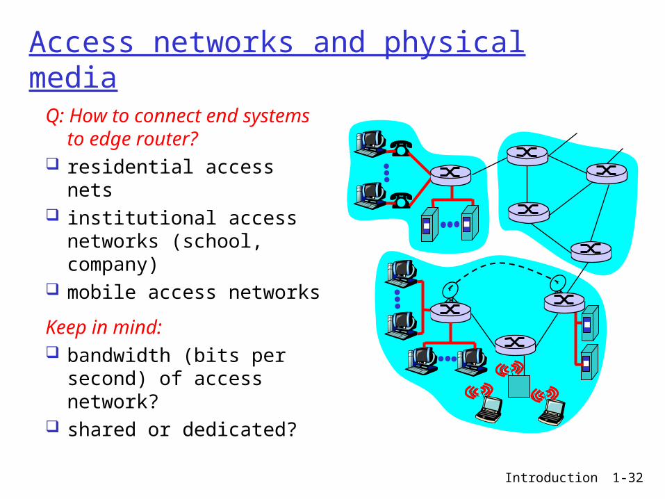
Access networks and physical media
Q: How to connect end systems to edge router?
residential access nets institutional access
networks (school, company)
mobile access networks
Keep in mind: bandwidth (bits per
second) of access network?
shared or dedicated?

Introduction 1-33
Residential access: point to point access
Dialup via modem up to 56Kbps direct access
to router (often less) Can’t surf and phone at
same time: can’t be “always on” ADSL: asymmetric digital subscriber line
up to 1 Mbps upstream (today typically < 256 kbps) up to 8 Mbps downstream (today typically < 1 Mbps) FDM: 50 kHz - 1 MHz for downstream 4 kHz - 50 kHz for upstream 0 kHz - 4 kHz for ordinary telephone

Introduction 1-34
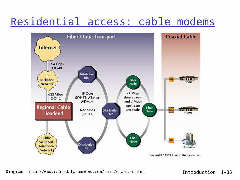
Residential access: cable modems
HFC: hybrid fiber coax asymmetric: up to 30Mbps downstream,
2 Mbps upstream network of cable and fiber attaches homes
to ISP router homes share access to router
deployment: available via cable TV companies
Introduction 1-35
Residential access: cable modems
Diagram: http://www.cabledatacomnews.com/cmic/diagram.html

Introduction 1-36
Cable Network Architecture: Overview
home
cable headend
cable distributionnetwork (simplified)
Typically 500 to 5,000 homes

Introduction 1-37
Cable Network Architecture: Overview
home
cable headend
cable distributionnetwork (simplified)

Introduction 1-38
Cable Network Architecture: Overview
home
cable headend
cable distributionnetwork
server(s)

Introduction 1-39
Cable Network Architecture: Overview
home
cable headend
cable distributionnetwork
Channels
VIDEO
VIDEO
VIDEO
VIDEO
VIDEO
VIDEO
DATA
DATA
CONTROL
1 2 3 4 5 6 7 8 9
FDM:

Introduction 1-40
Company access: local area networks
company/univ local area network (LAN) connects end system to edge router
Ethernet: shared or dedicated
link connects end system and router
10 Mbs, 100Mbps, Gigabit Ethernet
LANs: chapter 5
Introduction 1-41
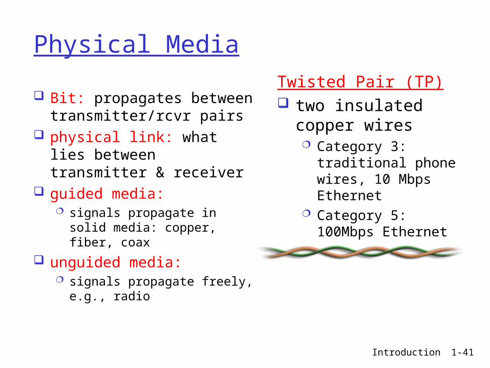
Physical Media
Bit: propagates betweentransmitter/rcvr pairs
physical link: what lies between transmitter & receiver
guided media: signals propagate in solid
media: copper, fiber, coax
unguided media: signals propagate freely,
e.g., radio
Twisted Pair (TP) two insulated copper
wires Category 3: traditional
phone wires, 10 Mbps Ethernet
Category 5: 100Mbps Ethernet

Introduction 1-42
Physical Media: coax, fiber
Coaxial cable: two concentric copper
conductors bidirectional baseband:
single channel on cable legacy Ethernet
broadband: multiple channel on
cable HFC
Fiber optic cable: glass fiber carrying light
pulses, each pulse a bit high-speed operation:
high-speed point-to-point transmission (e.g., 5 Gps)
low error rate: repeaters spaced far apart ; immune to electromagnetic noise

Introduction 1-43
Physical media: radio
signal carried in electromagnetic spectrum
no physical “wire” bidirectional propagation
environment effects: reflection obstruction by objects interference
Radio link types: terrestrial microwave
e.g. up to 45 Mbps channels
LAN (e.g., Wifi) 2Mbps, 11Mbps
wide-area (e.g., cellular) e.g. 3G: hundreds of kbps
satellite up to 50Mbps channel (or multiple
smaller channels) 270 msec end-end delay geosynchronous versus low altitude

Introduction 1-44
Chapter 1: roadmap
1.1 What is the Internet?1.2 Network edge1.3 Network core1.4 Network access and physical media1.5 Internet structure and ISPs1.6 Delay & loss in packet-switched
networks1.7 Protocol layers, service models1.8 History

Introduction 1-45
Internet structure: network of networks
roughly hierarchical at center: “tier-1” ISPs (e.g., UUNet, BBN/Genuity,
Sprint, AT&T), national/international coverage treat each other as equals
Tier 1 ISP
Tier 1 ISP
Tier 1 ISP
Tier-1 providers interconnect (peer) privately
NAP
Tier-1 providers also interconnect at public network access points (NAPs)
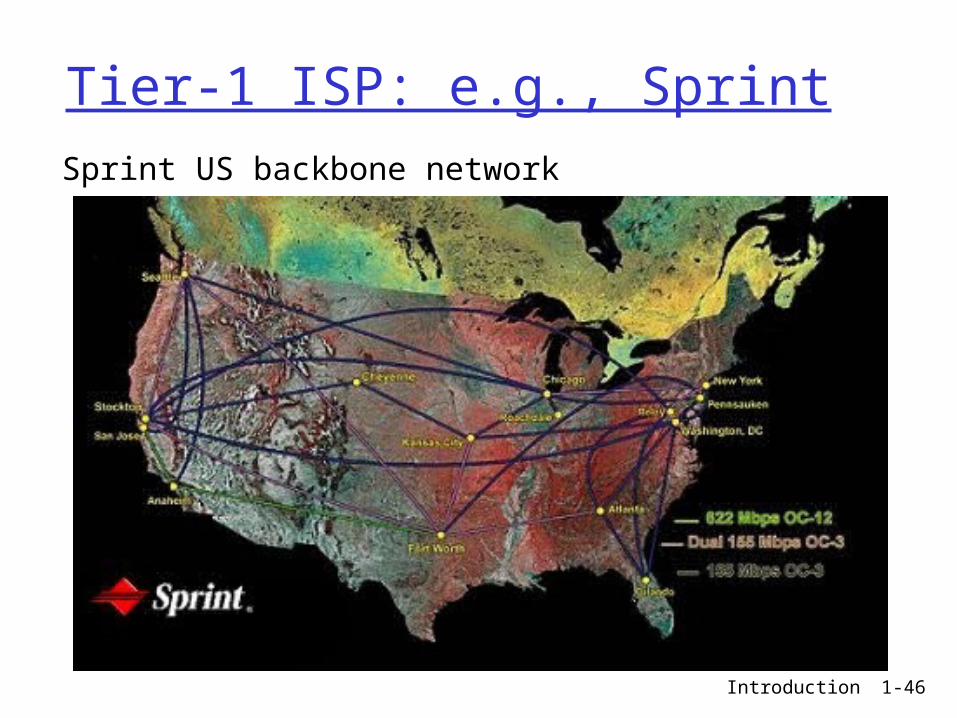
Introduction 1-46
Tier-1 ISP: e.g., SprintSprint US backbone network

Introduction 1-47
Internet structure: network of networks
“Tier-2” ISPs: smaller (often regional) ISPs Connect to one or more tier-1 ISPs, possibly other tier-2 ISPs
Tier 1 ISP
Tier 1 ISP
Tier 1 ISP
NAP
Tier-2 ISPTier-2 ISP
Tier-2 ISP Tier-2 ISP
Tier-2 ISP
Tier-2 ISP pays tier-1 ISP for connectivity to rest of Internet tier-2 ISP is customer oftier-1 provider
Tier-2 ISPs also peer privately with each other, interconnect at NAP

Introduction 1-48
Internet structure: network of networks
“Tier-3” ISPs and local ISPs last hop (“access”) network (closest to end systems)
Tier 1 ISP
Tier 1 ISP
Tier 1 ISP
NAP
Tier-2 ISPTier-2 ISP
Tier-2 ISP Tier-2 ISP
Tier-2 ISP
localISPlocal
ISPlocalISP
localISP
localISP Tier 3
ISP
localISP
localISP
localISP
Local and tier- 3 ISPs are customers ofhigher tier ISPsconnecting them to rest of Internet

Introduction 1-49
Internet structure: network of networks
a packet passes through many networks!
Tier 1 ISP
Tier 1 ISP
Tier 1 ISP
NAP
Tier-2 ISPTier-2 ISP
Tier-2 ISP Tier-2 ISP
Tier-2 ISP
localISPlocal
ISPlocalISP
localISP
localISP Tier 3
ISP
localISP
localISP
localISP
Introduction 1-50
Chapter 1: roadmap
1.1 What is the Internet?1.2 Network edge1.3 Network core1.4 Network access and physical media1.5 Internet structure and ISPs 1.6 Delay & loss in packet-switched
networks1.7 Protocol layers, service models1.8 History

Introduction 1-51
How do loss and delay occur?packets queue in router buffers packet arrival rate to link exceeds output link
capacity packets queue, wait for turn
A
B
packet being transmitted (delay)
packets queueing (delay)
free (available) buffers: arriving packets dropped (loss) if no free buffers

Introduction 1-52
Four sources of packet delay
1. nodal processing: check bit errors determine output link
A
B
propagation
transmission
nodalprocessing queueing
2. queueing time waiting at output
link for transmission depends on congestion
level of router
Introduction 1-53
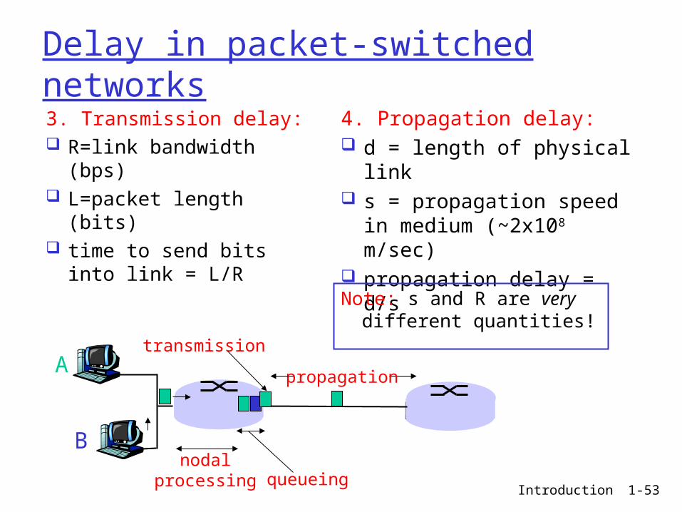
Delay in packet-switched networks3. Transmission delay: R=link bandwidth
(bps) L=packet length (bits) time to send bits into
link = L/R
4. Propagation delay: d = length of physical
link s = propagation speed in
medium (~2x10⁸ m/sec) propagation delay = d/s
A
B
propagation
transmission
nodalprocessing queueing
Note: s and R are very different quantities!

Introduction 1-54
Caravan analogy
Cars “propagate” at 100 km/hr
Toll booth takes 12 sec to service a car (transmission time)
car~bit; caravan ~ packet Q: How long until caravan
is lined up before 2nd toll booth?
Time to “push” entire caravan through toll booth onto highway = 12*10 = 120 sec
Time for last car to propagate from 1st to 2nd toll both: 100km/(100km/hr)= 1 hr
A: 62 minutes
toll booth
toll booth
ten-car caravan
100 km
100 km

Introduction 1-55
Caravan analogy (more)
Cars now “propagate” at 1000 km/hr
Toll booth now takes 1 min to service a car
Q: Will cars arrive to 2nd booth before all cars serviced at 1st booth?
Yes! After 7 min, 1st car at 2nd booth and 3 cars still at 1st booth.
1st bit of packet can arrive at 2nd router before packet is fully transmitted at 1st router! See Ethernet applet at AWL
Web site
toll booth
toll booth
ten-car caravan
100 km
100 km

Introduction 1-56
Nodal delay
dproc = processing delay typically a few microsecs or less
dqueue = queuing delay depends on congestion
dtrans = transmission delay = L/R, significant for low-speed links
dprop = propagation delay a few microsecs to hundreds of msecs
proptransqueueprocnodal ddddd
Introduction 1-57
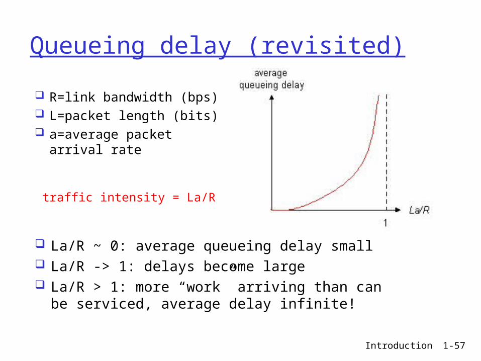
Queueing delay (revisited)
R=link bandwidth (bps) L=packet length (bits) a=average packet
arrival rate
traffic intensity = La/R
La/R ~ 0: average queueing delay small La/R -> 1: delays become large La/R > 1: more “work” arriving than can
be serviced, average delay infinite!

Introduction 1-58
“Real” Internet delays and routes What do “real” Internet delay & loss look like? Traceroute program: provides delay
measurement from source to router along end-end Internet path towards destination. For all i: sends three packets that will reach router i on path
towards destination router i will return packets to sender sender times interval between transmission and reply.
3 probes
3 probes
3 probes

Introduction 1-59
Packet loss
queue (aka buffer) preceding link in buffer has finite capacity
when packet arrives to full queue, packet is dropped (aka lost)
lost packet may be retransmitted by previous node, by source end system, or not retransmitted at all
Introduction 1-60
Chapter 1: roadmap
1.1 What is the Internet?1.2 Network edge1.3 Network core1.4 Network access and physical media1.5 Internet structure and ISPs1.6 Delay & loss in packet-switched
networks1.7 Protocol layers, service models1.8 History

Introduction 1-61
Protocol “Layers”Networks are
complex! many “pieces”:
hosts routers links of various
media applications protocols hardware,
software
Question: Is there any hope of organizing structure of
network?
Or at least our discussion of networks?

Introduction 1-62
Organization of air travel
a series of steps
ticket (purchase)
baggage (check)
gates (load)
runway takeoff
airplane routing
ticket (complain)
baggage (claim)
gates (unload)
runway landing
airplane routing
airplane routing

Introduction 1-63
ticket (purchase)
baggage (check)
gates (load)
runway (takeoff)
airplane routing
departureairport
arrivalairport
intermediate air-trafficcontrol centers
airplane routing airplane routing
ticket (complain)
baggage (claim
gates (unload)
runway (land)
airplane routing
ticket
baggage
gate
takeoff/landing
airplane routing
Layering of airline functionality
Layers: each layer implements a service via its own internal-layer actions relying on services provided by layer below

Introduction 1-64
Why layering?
Dealing with complex systems: explicit structure allows identification,
relationship of complex system’s pieces layered reference model for discussion
modularization eases maintenance, updating of system change of implementation of layer’s service
transparent to rest of system e.g., change in gate procedure doesn’t
affect rest of system layering considered harmful?
Introduction 1-65
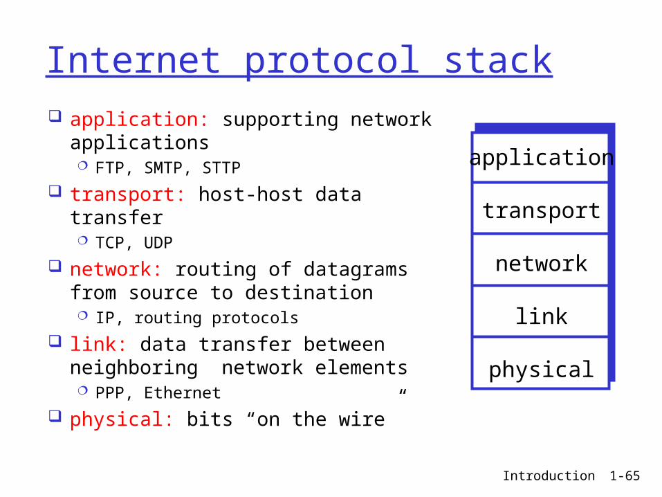
Internet protocol stack application: supporting network
applications FTP, SMTP, STTP
transport: host-host data transfer TCP, UDP
network: routing of datagrams from source to destination IP, routing protocols
link: data transfer between neighboring network elements PPP, Ethernet
physical: bits “on the wire”
application
transport
network
link
physical

Introduction 1-66
messagesegment
datagram
frame
sourceapplicatio
ntransportnetwork
linkphysical
HtHnHl M
HtHn M
Ht M
M
destination
application
transportnetwork
linkphysical
HtHnHl M
HtHn M
Ht M
M
networklink
physical
linkphysical
HtHnHl M
HtHn M
HtHnHl M
HtHn M
HtHnHl M HtHnHl M
router
switch
Encapsulation
Introduction 1-67
Chapter 1: roadmap
1.1 What is the Internet?1.2 Network edge1.3 Network core1.4 Network access and physical media1.5 Internet structure and ISPs1.6 Delay & loss in packet-switched
networks1.7 Protocol layers, service models1.8 History

Introduction 1-68
Internet History
1961: Kleinrock - queueing theory shows effectiveness of packet-switching
1964: Baran - packet-switching in military nets
1967: ARPAnet conceived by Advanced Research Projects Agency
1969: first ARPAnet node operational
1972: ARPAnet
demonstrated publicly NCP (Network Control
Protocol) first host-host protocol
first e-mail program ARPAnet has 15 nodes
1961-1972: Early packet-switching principles

Introduction 1-69
Internet History
1970: ALOHAnet satellite network in Hawaii
1973: Metcalfe’s PhD thesis proposes Ethernet
1974: Cerf and Kahn - architecture for interconnecting networks
late70’s: proprietary architectures: DECnet, SNA, XNA
late 70’s: switching fixed length packets (ATM precursor)
1979: ARPAnet has 200 nodes
Cerf and Kahn’s internetworking principles: minimalism, autonomy
- no internal changes required to interconnect networks
best effort service model
stateless routers decentralized control
define today’s Internet architecture
1972-1980: Internetworking, new and proprietary nets

Introduction 1-70
Internet History
Early 1990’s: ARPAnet decommissioned
1991: NSF lifts restrictions on commercial use of NSFnet (decommissioned, 1995)
early 1990s: Web hypertext [Bush 1945,
Nelson 1960’s] HTML, HTTP: Berners-Lee 1994: Mosaic, later
Netscape late 1990’s:
commercialization of the Web
Late 1990’s – 2000’s: more killer apps: instant
messaging, P2P file sharing
network security to forefront
est. 50 million host, 100 million+ users
backbone links running at Gbps
1990, 2000’s: commercialization, the Web, new apps

Introduction 1-71
Introduction: Summary
Covered a “ton” of material! Internet overview what’s a protocol? network edge, core,
access network packet-switching
versus circuit-switching Internet/ISP structure performance: loss, delay layering and service
models history
You now have: context, overview,
“feel” of networking more depth, detail
to follow!


![Introduction1 [Compatibility Mode]](https://static.fdocuments.us/doc/165x107/577cd5b71a28ab9e789b74c4/introduction1-compatibility-mode.jpg)