Introduction to the 1988 edition - Builder Assist · The Building Code of Australia (BCA) is a...
209
Transcript of Introduction to the 1988 edition - Builder Assist · The Building Code of Australia (BCA) is a...

Introduction to the 1988 edition
BCA 1988 edition This edition of the Building Code of Australia marks an important step towards the achievement of uniform building regulations throughout Australia.
State and Territory variations and additions State and Territory legislation is able to adopt this Code subject to the variation or deletion of some of the provisions, or the addition of extra provisions to apply in the particular State or Territory concerned.
Administrations are now proceeding to identify these variations and other building related issues (if any) to enable adoption during 1989. A series of separately printed Appendices to the Code setting out the nature of these variations will be issued for each State and Territory. The first of these Appendices will be available at BCA outlets early in 1989.
Amendments and future editions The Code will be reprinted towards the end of 1989 to enable the inclusion of the State and Territory appendices in a single volume and to insert references in the margin of the BCA to identify where variations have been made by any State or Territory.
Future editions of the Code will be current for up to 3 years.
BCA amendment pages will be issued annually to reflect improvements resulting from research, technology development and experience in the practical application of the requirements of the Code
PREFACE
About this Code The Building Code of Australia (BCA) is a development of the Australian Model Uniform Building Code (AMUBC) and a major advance in establishing a uniform set of technical requirements and standards for the design and construction of buildings and other structures throughout Australia.
Its basic objective is to ensure that acceptable standards of structural sufficiency, fire safety, health and amenity, are maintained for the benefit of the community now and in the future.
The requirements included in this Code are intended to extend no further than is necessary in the public interest, to be cost effective, not needlessly onerous in their application, and easily understood.

What is in the Code ? The BCA sets down the Objectives, Performance Requirements and Deemed-to-Satisfy Provisions which apply to the construction of buildings for all classes of occupancy in any part of Australia.
It allows for variations in climate and geological or geographic conditions.
It must however be recognised that a building code cannot cover every issue concerned with the design and construction of buildings. In the case of innovative, complex or unusually hazardous building proposals, or other building work beyond the scope of the Code, legislation may provide for the application to be referred to a Board or Committee of Referees.
The BCA covers those aspects of building which are controlled by local government such as structure, fire resistance, access and egress, fire-fighting equipment, mechanical ventilation, lift installations, and certain aspects of health and amenity. It does not apply to the technical details of services such as plumbing, electrical services, lifts or moving walkways, or to other aspects of design or construction not normally covered by building regulations.
Objectives of the provisions Broad statements of intent are included at the beginning of each Section to identify the objectives that the provisions of the Section are intended to achieve.
The Objectives are the basic concepts which apply generally to all buildings and structures. The provisions of each Part of the Code are accepted by the Authorities as meeting the Objectives.
Performance requirements In some cases the provisions are expressed in performance terms. Accreditation Certificates, test reports or other documentary evidence may be used as evidence that a particular material, design or construction method meets the performance requirements of this Code.
Deemed-to-satisfy provisions Where a provision states that the use of a particular material, component, method of construction or design satisfies a performance requirement of this Code, that provision does not require its use. An equivalent material, component, method or design may be used if it meets the level of performance prescribed by the provision concerned.
This Code allows for the StandardsMark product certification by Standards Australia to be used as evidence of compliance with particular requirements or Standards
Professional certification The BCA allows for certificates from professional consultants to be used as evidence of compliance with particular requirements or standards.
The enabling legislation will determine the extent of the use of professional certification and the procedures for the submission of certificates, reports or other documentation to Approval Authorities as evidence of compliance.
Layout of the BCA The arrangement of the text of the BCA varies from existing AMUBC based regulations and by-laws in order to close up the gaps caused by the removal of the administrative provisions and as a first step in rationalising the sequence of the clauses.
The numbering of Sections and Parts has been changed to an alpha-numeric system for ease of reference and to avoid confusion with the AMUBC. It also provides flexibility to accommodate future additions or deletions and the future consolidation of building regulations presently contained in other legislation, without undue disruption to the layout.
Words with special meanings The words printed in italics have special meanings and are defined in clause ý A1.1. ý
Definitions and terminology used in this Code are as far as possible consistent ý with that used in State and Territory legislation, however where there is any ý conflict, the requirements of legislation take precedence. ý
Administrative arrangements This Code is brought into effect by enabling building control legislation in each State and Territory which prescribes or "calls up" the technical requirements which have to be satisfied in order to gain approval.
The enabling legislation consists of an Act of Parliament and subordinate legislation, and empowers the administration to regulate certain aspects of the building process and contains the necessary administrative provisions which confer powers on the Local Authority, impose responsibilities on the authorities or other persons or bodies, and describe particular administrative procedures.
The following administrative type matters are covered in the enabling or subordinate legislation-
. Plan submission and approval procedures.
. Issue of building permits.
. Inspections during and after construction.
. Provision of evidentiary certificates.
. Issue of certificates of occupancy or compliance.

. Accreditation or approval of materials or components.
. Review and enforcement of standards.
. Fees and charges.
Administrative discretions The BCA is drafted with the objective of reducing the need for the building ý authority to make discretionary decisions. ý
However, in many cases it is not possible to draft a provision in purely technical ý terms and an informed judgement is required on the standard which would be ý suitable in particular circumstances. ý
Accordingly, in a number of clauses, the Code requires a particular material or ý construction method to be "suitable", meaning fit in all relevant respects for its ý intended purpose and use. ý
The Local Authority responsible for the enforcement of building controls retains ý the right to question "suitability" and differences of opinion are open to appeal. ý
Further development of the BCA This Code is the first stage in an on-going comprehensive reformulation and simplification of the building regulations which apply in Australia. Part of this process will be the conversion of more of the existing prescriptive requirements to performance/deemed-to-satisfy provisions.
In addition, AUBRCC has initiated a number of research projects to review and develop parts of the Code and to improve its layout and presentation.
Amendments to the Code will be made progressively as these projects are completed. The continuous review of the Code will enable its provisions to be more readily kept up-to-date with changes in technology.
Comments The BCA is maintained by AUBRCC on behalf of the Commonwealth, State and Territory Administrations. Comments in writing on any matter concerning the text, presentation or further development of the Code are invited from building and other authorities, industry organisations, professional operatives and the public generally, addressed to-
The Directorate
AUBRCC
Department of Industry, Technology and Commerce
GPO Box 9839
CANBERRA A.C.T. 2601.

AUBRCC AUBRCC is responsible to the Local Government Ministers' Conference (LGMC). It is established by agreement between the Commonwealth and the States and Territories with provision for Local Government and building industry representation.
Council - The AUBRCC Council reports to the LGMC on policy, procedures, research priorities and funding arrangements, and comprises the representatives of:
New South Wales - Department of Local Government.
Victoria - Ministry for Planning and Environment.
Queensland - Local Government Department.
Western Australia - Department of Local Government.
South Australia - Department of Local Government.
Tasmania - Local Government Office.
Australian Capital Territory - ACT Administration, Department of Arts, Sport, the Environment, Tourism and Territories.
Northern Territory - Department of Lands and Housing.
ACLGA - Australian Council of Local Government Associations.
Commonwealth - Department of Industry, Technology and Commerce.
Directorate - The AUBRCC Directorate is provided by the Commonwealth Department of Industry, Technology and Commerce.
Executive Committee - The AUBRCC Executive Committee consists of the principal building control officer in each State and Territory from:
NSW - Department of Local Government.
VIC - Ministry for Planning and Environment.
QLD - Local Government Department.
WA - Department of Local Government.
SA - Department of Local Government.
Tas - Local Government Office.
ACT - Administration, Department of Arts, Sport, the Environment, Tourism and Territories.
NT - Department of Lands and Housing.
and representatives from:
ACLGA - Australian Council of Local Government Associations.
C'Wealth - Department of Industry, Technology and Commerce.

Advisers representing the private sector building industry and the Australian Assembly of Fire Authorities attend Executive Committee meetings.
Technical Adviser - The National Building Technology Centre is the technical adviser to AUBRCC.
The following organisations are represented on AUBRCC Technical Committees:
Ancillary Provisions Committee
Ministry for Planning and Environment, Victoria. (chair) ý
Association of Consulting Engineers, Australia. ý
Australian Assembly of Fire Authorities. ý
Australian Fire Protection Association. ý
Australian Institute of Building Surveyors (Vic Chapter). ý
Building Owners & Managers Association Ltd. ý
Insurance Council of Australia. ý
Melbourne City Council. ý
National Building Technology Centre. ý
Royal Australian Institute of Architects (Vic Chapter). ý
Editorial Committee
AUBRCC Directorate. (chair) ý
Victoria Ministry for Planning and Environment. ý
NSW Department of Local Government. ý
Fire Committee
NSW Department of Local Government. (chair). ý
Australian Assembly of Fire Authorities. ý
Australian Institute of Building. ý
Australian Institute of Building Surveyors (NSW Chapter). ý
Building Owners & Managers Association Ltd. ý
Institution of Engineers, Australia. ý
National Building Technology Centre. ý
Royal Australian Institute of Architects (NSW Chapter). ý
General Provisions Committee
Ministry for Planning and Environment, Victoria. (chair). ý
Australian Institute of Building Surveyors (Vic Chapter). ý
Housing Industry Association (Vic Division). ý
Master Builders' Association of Victoria. ý

Royal Australian Institute of Architects (Vic Chapter).
Health and Amenity Committee
WA Department of Local Government. (chair). ý
WA Building Management Authority. ý
City of Perth Council. ý
Royal Australian Institute of Architects (WA Chapter). ý
Master Builders' Association of WA. ý
Western Australia Fire Brigades Board. ý
Association of Consulting Engineers, Australia. ý
Local Government Association of WA. ý
Industry Liaison Committee - representing sectors of the building industry through:
National Building and Construction Council. (chair).
Australian Institute of Building.
Australian Institute of Building Surveyors.
Australian Federation of Construction Contractors.
Building Industry Specialist Contractors Organisation of Australia.
Building Owners & Managers' Association Ltd.
Housing Industry Association.
Master Builders' Construction & Housing Association, Australia.
Royal Australian Institute of Architects.
Services and Equipment Committee
SA Department of Local Government. (chair). ý
Association of Consulting Engineers, Australia. ý
Australian Assembly of Fire Authorities. ý
Australian Council of Local Government Associations. ý
Australian Fire Protection Association. ý
Australian Institute of Building. ý
Australian Institute of Building Surveyors (SA Chapter). ý
Building Owners & Managers' Association Ltd. ý
Institution of Engineers, Australia. ý
Royal Australian Institute of Architects. ý
Structural Committee
Queensland Local Government Department. (chair). ý
Association of Consulting Engineers, Australia. ý
Australian Institute of Building. ý
Brick Development Research Institute. ý
Cement and Concrete Association. ý
Concrete Masonry Association. ý
Institution of Engineers, Australia. ý
Queensland Department of Works. ý
Queensland Institute of Technology. ý
Queensland Master Builders' Association. ý
Timber Research and Development Advisory Council. ý
***************************************************************************************** ý
SECTION A GENERAL PROVISIONS
CONTENTS
A1 Interpretation A1.1 Definitions
A1.2 Adoption of Standards and other references
A1.3 Referenced Standards, etc
A1.4 Differences between referenced documents and this Code
A1.5 Application of this Code to a particular State or Territory
A2 Acceptance of and Construction A2.1 Suitability of materials ý
A2.2 Evidence of suitability ý
A2.3 Fire-resistance of building elements ý
A2.4 Early Fire Hazard Indices ý
A3 Classification Buildings and Structures A3.1 Principles of classification ý
A3.2 Classifications ý
A3.3 Multiple classification ý
A4 United Buildings A4.1 When buildings are united ý
A4.2 Alterations in a united building ý
Specifications Specification A1.3 Standards Adopted by Reference.
Specification A2.3 Fire-Resistance of Building Elements.
Specification A2.4 Early Fire Hazard Test for Assemblies.
A1 INTERPRETATION
A1.1 Definitions Alpine area means land-

(a) in New South Wales, A.C.T. or Victoria more than 1200 m above the Australian Height Datum;
(b) in Tasmania more than 900 m above the Australian Height Datum; or
(c) likely to be subject to significant snowfalls.
Alteration, in relation to a building, includes an addition or extension to a building.
Assembly building means a building where people may assemble for-
(a) ý civic, theatrical, social, political or religious purposes;
(b) ý educational purposes in a school, early childhood centre, preschool, or the like;
(c) ý entertainment, recreational or sporting purposes; or
(d) ý transit purposes.
Atrium means a space within a building that connects 2 or more storeys, and-
(a) ý is wholly or substantially enclosed at the top by a floor or roof (including a glazed roof structure); and
(b) ý includes any adjacent part of the building not separated by bounding construction in accordance with Part G3; but
(c) ý does not include a stairwell, rampwell or the space within a shaft.
Atrium well means a space in an atrium bounded by the perimeter of the openings in the floors or by the perimeter of the floors and the external walls.
Automatic, applied to a fire door, smoke door, fire shutter, smoke-and-heat vent, sprinkler system, alarm system or the like, means designed to operate when activated by a heat, smoke or fire sensing device.
Backstage means a space associated with, and adjacent to, a stage in a Class 9b building for scenery, props, equipment, dressing rooms, or the like.
Certificate of Accreditation means a certificate stating that the properties and performance of a building material or method of construction or design fulfil specific requirements of this Code.
Combustible -
(a) ý applied to a material - means combustible under AS 1530.1.
(b) ý applied to construction or part of a building -means constructed wholly or in part of combustible materials.
(See definition of non-combustible).
Common wall means a wall that is common to adjoining buildings.
Curtain wall means a non-loadbearing external wall that is not a panel wall.
Early childhood centre means a preschool, kindergarten or child-minding centre.
Effective height means the height to the floor of the topmost storey (excluding the topmost storey if it contains only heating, ventilating, lift or other equipment, water tanks or similar service units) from the floor of the lowest storey providing egress to a road or open space .
Exit means:
(a) ý Any, or any combination of the following if they provide egress to a road or open space:
(i) ý An internal or external stairway.
(ii) ý A ramp complying with Section D.
(iii) ý A fire-isolated passageway.
(iv) ý A doorway opening to a road or open space.
(b) ý A horizontal exit or a fire-isolated passageway leading to a horizontal exit.
External wall means an outer wall of a building which is not a common wall.
Fire compartment means a part of a building which is separated from the remainder in accordance with this Code to resist the spread of fire and smoke.
Fire-isolated passageway means a corridor, hallway or the like, of fire-resisting construction, which provides egress to or from a fire-isolated stairway or fire-isolated ramp or to a road or open space.
Fire-isolated ramp means a ramp within a fire-resisting enclosure which provides egress from a storey.
Fire-isolated stairway means a stairway within a fire-resisting shaft and includes the floor and roof or top enclosing structure.
Fire main means a water service pipe installed within a building or on a building allotment for fire-fighting purposes.
Fire-protective covering means-
(a) ý 13 mm fire-protective grade plasterboard;
(b) ý 12 mm mesh-reinforced fibrous plaster in which the mesh is 13 mm x 13 mm x 0.71 mm welded wire located not more than 6 mm from the exposed face; or
(c) ý other material not less fire-protective than 13 mm fire-protective grade plasterboard, fixed in accordance with the normal trade practice for a fire-protective covering.
Fire-resistance level (FRL) means the grading periods in minutes determined in accordance with Specification A2.3, for-
(a) ý structural adequacy;
(b) ý integrity; and
(c) insulation, ý
and expressed in that order. ý

Fire-resisting, applied to a structural member or other part of a building, means having the FRL required for that structural member or other part.
Fire-resisting construction means one of the Types of construction referred to in Part C1.
Fire-separated section means a part of a building which is separated from the remainder by fire walls in accordance with Part C2 and thereby regarded as a separate building.
Fire-source feature means-
(a) ý the far boundary of a road adjoining the allotment;
(b) ý a side or rear boundary of the allotment; or
(c) ý an external wall of another building on the allotment which is not of Class 10.
Fire wall means a wall that divides a storey or building to resist the spread of fire and smoke and has the FRL required under Specification C1.1.
Flammability Index means the index number determined under AS 1530.2.
Floor area means-
(a) ý in relation to a storey - the area of that storey measured over the enclosing walls (if any) and that part of any common wall located within the allotment; and
(b) ý in relation to a room- the area of the room measured within the finished surfaces of the walls, and includes the area occupied by any cupboard or other built-in furniture, fixture or fitting.
Foundation means the ground which supports the building.
Habitable room means a room used for normal domestic activities, and-
(a) ý includes a bedroom, living room, lounge room, music room, television room, kitchen, dining room, sewing room, study, playroom, family room and sunroom; but
(b) ý excludes a bathroom, laundry, water closet, pantry, walk-in wardrobe, corridor, hallway, lobby, photographic darkroom, clothes-drying room, and other spaces of a specialised nature occupied neither frequently nor for extended periods.
Health-care building means-
(a) ý a nursing home, hospital, convalescent home, infirmary or similar institution or home for sick or disabled persons needing full-time nursing care; or
(b) ý a clinic or day surgery unit where-
(i) ý prescribed surgical procedures are performed on people who do not require overnight care as in-patients in a hospital; and
(ii) ý the surgical procedures include a potential requirement for general anaesthesia, major regional anaesthesia or intravenous sedation.
Horizontal exit means a required doorway between 2 portions of a building separated from each other by a fire wall with an
FRL as required by Specification C1.1.
Hydrant means a fire hydrant or plug connected to a fire main or to a water main in a public road.
Insulation, in relation to an FRL, means the ability to maintain a temperature on the surface not exposed to the furnace below the limits specified in AS 1530.4.
Integrity, in relation to an FRL, means the ability to resist the passage of flames and hot gases specified in AS 1530.4.
Internal wall excludes a common wall or a party wall.
Lightweight construction see Specification C1.8.
Loadbearing means intended to resist forces and moments additional to those due to its own weight.
Mezzanine floor means an intermediate floor within a room which is not more than 1/3 of the floor area of the room or 200 m2, whichever is the lesser.
Non-combustible -
(a) ý applied to a material - means not combustible except that the material may have a combustible surface finish if the finish is not more than 1 mm thick and the Spread-of-Flame Index of the assemblage is 0;
(b) ý applied to construction or part of a building - means constructed wholly of materials that are non-combustible.
Open-deck carpark means a carpark in which all parts of the parking storeys are cross-ventilated by permanent unobstructed openings in not fewer than 2 opposite or approximately opposite sides, and-
(a) ý where each side that provides ventilation is not less than 1/6 of the area of any other side; and
(b) ý the openings are not less than 1/2 of the wall area of the side concerned.
Open garage means a carport or garage with 2 or more sides substantially open.
Open space means a space on an allotment, or a roof or similar part of a building complying with D2.12, open to the sky and connected directly with a public road.
Open spectator stand means a tiered stand substantially open at the front.
Panel wall means a non-loadbearing external wall, in frame or similar construction, that is wholly supported at each storey.
Private garage means-
(a) ý any garage of a Class 1 building; or
(b) ý any single storey of a building of another Class capable of accommodating not more than 3 vehicles, if there is only one such storey in the building.
Professional engineer means a person with appropriate experience in the relevant field, being-
(a) ý if legislation so requires - a registered professional engineer in the relevant discipline; or
(b) ý otherwise - a Corporate Member of the Institution of Engineers, Australia.
Public corridor means an enclosed corridor, hallway or the like which-
(a) ý serves as a means of egress from 2 or more sole-occupancy units to a required exit from the storey concerned; or
(b) ý is required to be provided as a means of egress from any portion of a storey to a required exit.
Public carpark means a building that is used for the parking of motor vehicles but is neither a private garage nor used for the servicing of vehicles, other than washing, cleaning or polishing.
Registered Testing Authority means -
(a) ý the National Building Technology Centre (NBTC);
(b) ý the CSIRO Division of Building, Construction and Engineering;
(c) ý an authority registered by the National Association of Testing Authorities (NATA) to test in the relevant field; or
(d) ý an organisation outside Australia recognised by NATA through a mutual recognition agreement.
Required means required by this Code.
Resistance to the incipient spread of fire in relation to a ceiling membrane, means the ability of a ceiling membrane to insulate the space between the ceiling and roof, or ceiling and floor above, to limit the temperature rise of combustibles in this space during the Standard Fire Test to 180 K.
Rise, in storeys, means the greatest number of storeys calculated in accordance with C1.2 at any part of the external walls of the building-
(a) ý above the finished ground next to that part; or
(b) ý if part of the external wall is on the boundary of the allotment, above the natural ground level at the relevant part of the boundary.
Sanitary compartment means a room or space containing a toilet fixture, closet pan, soil pan, chemical toilet, or the like.

Sarking-type material means a material such as a reflective foil or other flexible membrane of a type normally used for a purpose such as water-proofing, vapour proofing or thermal reflectance.
School includes a primary or secondary school, college, university or similar educational establishment.
Self-closing, applied to a door or window means equipped with a device which returns the door or window to the fully closed and latched position immediately after each manual opening.
Service station means a garage which is not a private garage and is for the servicing of vehicles, other than only washing, cleaning or polishing.
Shaft means the walls and other parts of a building bounding-
(a) ý a well, other than an atrium well; or
(b) ý a vertical chute, duct or similar passage, but not a chimney or flue.
Site means the part of the allotment of land on which a building stands or is to be erected.
Smoke-and-heat vent means a vent, located in or near the roof for smoke and hot gases to escape if there is a fire in the building.
Smoke-Developed Index means the index number for smoke developed under AS 1530.3.
Sole-occupancy unit means a room or other portion of a building for occupation by one owner, lessee, tenant, or other occupier to the exclusion of any other owner, lessee, tenant, or other occupier.
Spread-of-Flame Index means the index number for spread of flame under AS 1530.3.
Sprinkler system means a system of automatic fire sprinklers complying with E1.5.
Stage means a floor or platform in a Class 9b building on which performances are presented before an audience.
Standard Fire Test means the Fire-resistance Test of Structures under AS 1530.4.
Storey means a space within a building which is situated between one floor level and the floor level next above, or if there is no floor above, the ceiling or roof above, but not-
(a) ý a space that contains only-
(i) ý a lift shaft, stairway or meter room;
(ii) ý a bathroom, shower room, water closet, or other sanitary compartment; or
(iii) ý not more than 3 vehicles; or
(iv) ý a combination of the above; or
(b) a mezzanine.

Structural adequacy, in relation to an FRL means the ability to maintain stability and adequate loadbearing capacity under AS 1530.4.
Structural member means a component or part of an assembly which provides vertical or lateral support to a building or structure.
Swimming pool means any excavation or structure containing water and used for swimming, wading, paddling, or the like, including a bathing or wading pool, or spa.
Ward area means that portion of a storey of a Class 9a building for residing patients and includes areas for sleeping, recreation and sanitary facilities, and nurses stations.
Window includes a roof light, glass panel, glass brick, glass louvre, glazed sash, glazed door, or other device which transmits natural light directly from outside a building to the room concerned when in the closed position.
A1.2 ý Adoption of Standards and other references The adoption of a Standard, rule, specification or provision included in any document issued by the Standards Association of Australia or other body, does not include a provision-
(a) ý specifying the respective rights, responsibilities or obligations between that body and any manufacturer, supplier or purchaser;
(b) ý specifying the responsibilities of any tradesman or other building operative, architect, engineer, authority, or other person or body;
(c) ý requiring the submission for approval of any material, building component, form or method of construction, to any person, authority or other body;
(d) ý specifying that a material, building component, form or method of construction, must be submitted to the Standards Association of Australia or a committee of the Association for expression of opinion; or
(e) ý permitting a departure from the code, rule, specification or provision at the sole discretion of the manufacturer or purchaser, or by arrangement or agreement between the manufacturer and purchaser.
A1.3 ý Referenced Standards, etc A reference to a document under A1.2 refers to the edition or issue, together with any amendment, listed in Specification A1.3 and only so much as is relevant in the context in which the document is quoted.
A1.4 ý Differences between referenced documents and this Code
This Code overrules in any difference arising between it and any Standard, rule, specification or provision in a document listed in Specification A1.3.

A1.5 ý Application of this Code to a particular State or Territory
For application within a particular State or Territory, this Code comprises-
(a) ý Sections A to H including marginal references to variations and additions applicable to that State or Territory; and
(b) ý the variations and additions to Sections A to H applicable to that State or Territory specified in the Appendix.
A2 ACCEPTANCE OF DESIGN AND CONSTRUCTION
A2.1 ý Suitability of materials Every part of a building must be constructed in a proper and workmanlike manner to achieve the required level of performance, using materials that are not faulty or unsuitable for the purpose for which they are intended.
A2.2 ý Evidence of suitability Subject to A2.3 and A2.4, evidence to support the use of a material, form of construction or design may be-
(a) ý a report issued by a Registered Testing Authority, showing that the material or form of construction has been submitted to the tests listed in the report, and setting out the results of those tests and any other relevant information that demonstrates its suitability for use in the building;
(b) ý a current Certificate of Accreditation;
(c) ý a certificate from a professional engineer or other appropriately qualified person which-
(i) ý certifies that a material, design or form of construction complies with the requirements of this Code; and
(ii) sets out the basis on which it is given and the extent to which relevant specifications, rules, codes of practice or other publications have been relied upon;
(d) ý as StandardsMark Certificate issued by Standards Australia; or
(e) ý any other form of documentary evidence that correctly describes the properties and performance of the material or form of construction and adequately demonstrates its suitability for use in the building,
and any copy of documentary evidence submitted under this Code, must be a complete copy of the original report or document.
A2.3 ý Fire-resistance of building elements The FRL of a structural member or other building element must be determined in accordance with Specification A2.3.
A2.4 Early Fire Hazard Indices The Early Fire Hazard Indices of a component or assembly must be determined in accordance with Specification A2.4
A3 ý CLASSIFICATION OF BUILDINGS AND STRUCTURES
A3.1 Principles of classification The classification of a building or part of a building is determined by the purpose for which it is designed, constructed or adapted to be used.
A3.2 Classifications Buildings are classified as follows:
Class 1: a residence which may comprise one or more buildings including any habitable outbuildings which in association constitute-
(a) ý a single dwelling-house; or
(b) ý a terrace house, townhouse or the like which may be detached or separated by a common wall; or
(c) ý a dwelling-house used as a boarding-house, hostel, or the like, in which not more than 12 persons would ordinarily be resident; or
(d) ý a building that does not exceed a rise of 3 storeys and contains-
(i) ý 2 or more sole-occupancy units where no such unit is located one above the other; or
(ii) ý only 2 sole-occupancy units located one above the other, and each unit has direct egress to a road or open space.
Class 2: a building containing 2 or more sole-occupancy units each being a separate dwelling, other than a building of Class 1.
Class 3: a residential building, other than a building of Class 1 or 2, which is a common place of living for a number of unrelated persons, including-
(a) ý a boarding-house, guest house, hostel, or lodging-house;
(b) ý a residential part of an hotel or motel;
(c) ý a residential part of a school;
(d) ý accommodation for the aged, disabled or children; and
(e) ý a residential part of a health-care building which accommodates members of staff.
Class 4: a dwelling in a building that is Class 5, 6, 7, 8 or 9 if it is the only dwelling in the building.
Class 5: an office building used for professional or commercial purposes, excluding buildings of Class 6, 7 or 8.

Class 6: a shop or other building for the sale of goods by retail or the supply of services direct to the public, including-
(a) ý an eating room, cafe, restaurant, milk or soft-drink bar;
(b) ý a dining room, bar, shop or kiosk portion of an hotel or motel;
(c) ý a hairdresser's or barber's shop, public laundry, or undertaker's establishment;
(d) ý market or sale room, show room, or service station.
Class 7: a building which is-
(a) ý a public carpark; or
(b) ý for storage, or display of goods or produce for sale by wholesale.
Class 8: a laboratory, or a building in which a handicraft or process for the production, assembling, altering, repairing, packing, finishing, or cleaning of goods or produce is carried on for trade, sale, or gain.
Class 9: a building of a public nature-
(a) ý Class 9a - a health-care building;
(b) Class 9b - an assembly building, and
Class 9a includes a pathology laboratory in a health-care building and Class 9b includes a trade workshop in a primary or secondary school, but excludes any other part of these buildings that are of another Class.
Class 10: a non-habitable outbuilding or structure-
(a) ý Class 10a - a carport, private garage, shed, or the like;
(b) ý Class 10b - a fence, mast, antenna, retaining or free-standing wall, swimming pool, or the like.
A3.3 Multiple classification Each part of a building must be classified separately, and-
(a) ý where parts have different purposes - if not more than 10% of the floor area of a storey which is not a laboratory is used for a purpose which is a different classification, the classification applying to the major use may apply to the whole storey;
(b) ý Classes 9a, 9b, 10a and 10b are separate classifications; and
(c) ý a reference to-
(i) ý Class 9 - is to Class 9a or 9b; and
(ii) ý Class 10 - is to Class 10a or 10b.
A4 UNITED BUILDINGS
A4.1 When buildings are united 2 or more buildings adjoining each other are considered to form one united building if they-
(a) ý are connected through openings in the walls dividing them; and
(b) ý together comply with all the requirements of this Code as though they are a single building.
A4.2 Alterations in a united building After any alteration or any other action-
(a) ý a united building; or
(b) ý each building forming part of a united building; or
(c) ý each building if they cease to be connected through openings in the dividing walls,
must comply with all requirements for a single building.
SPECIFICATION A1.3 ý STANDARDS ADOPTED BY REFERENCE
1. ý Schedule of referenced documents The Standards and other documents listed in Table 1 are referred to
in this Code.
TABLE 1: SCHEDULE OF REFERENCED DOCUMENTS No. Date Title BCA
Clause(s)
AS 1038 Methods for the analysis and testing of coal and coke
Part 15 1972 Fusibility of higher rank coal ash and coke ash Spec C3.15
AS 1170 Minimum design loads on structures (SAA Loading Code)
B1.2
Part 1 1981 Dead and live loads
Part 2 1983 Wind forces
AS 1191 1985 Acoustics- Method for laboratory measurement of airborne sound transmission loss of building partitions
Spec F5.5
AS 1200 1981 Boilers and pressures vessels (SAA Boiler Code)
G2.2
AS 1221 1983 Fire hose reels E1.4
AS 1250 1981 The use of steel in structures Spec A2.3,

AS 1276 1979
AS 1288
Part 1 1979
Part 2 1979
Part 3 1979
AS 1349 1986
AS 1428
Part 1 1988
AS 1475
Part 1 1977
Part 2 1983
AS 1529 1974
AS 1530
Part 1 1984
Part 2 1973
Part 3 1985
Part 4 1985
Note:
AS 1538 1974
AS 1562 1980
AS 1603
AS 1640 1974
AS 1657 1974
AS 1664 1979
AS 1668
(SAA Steel Structures Code) B1.3 Amdt 2, Oct. 1984
Methods for determination of Sound F5.2 Transmission Class and Noise Isolation Class of building partitions
Rules for installation of glass in buildings B1.3 (SAA Glass Installation Code)
Selection of glass
Glazing techniques
Unframed toughened glass assemblies
Bourdon tube pressure and vacuum gauges Spec E1.2
Design rules for access by the disabled
Regulatory requirements D3.2, D3.3 F2.6
Concrete blockwork in buildings (SAA Blockwork Code)
Unreinforced blockwork B1.3 Amdt 1, Sept 1983 Amdt 2, Oct 1986
Reinforced blockwork B1.3 Amdt 1, July 1983 Amdt 2, Oct 1986
Code of practice for installation of household-type G1.3 hot water supply systems
Methods of fire tests on building materials A1.1 components and structures
Combustibility test for materials
Test for flammability of materials
Test for early fire hazard properties of materials Spec A2.4
Fire-resistance tests on elements of building Spec A2.4 construction Spec C3.15
Previous test reports under Part 1-1976, Part 3-1982 and Part 4-1975 remain valid. New reports of tests carried out after the date of amendment must relate to the amended Standard
Rules for the use of cold-formed steel in B1.3 structures (SAA Cold-formed Steel Structures Code)
Design and installation of metal roofing B1.3, F1.5
Thermal detectors for fire alarm installations Spec E1.7
Rules for brickwork in buildings B1.3, (SAA Brickwork Code) Spec A2.3
Rules for fixed platforms, walkways, stairways D2.18, H1.6 and ladders
Rules for the use of aluminium in structures B1.3 (SAA Aluminium Structures Code)
Rules for the use of mechanical ventilation and
air-conditioning in buildings (SAA Mechanical Ventilation and Air-conditioning Code)
Part 1 1979 Fire precautions in buildings with air-handling C3.15, systems Spec E1.7 Amdt 1, Nov. 1979 Spec E1.8
E2.3, E2.7, Spec E2.3, Spec G3.8, Spec H1.2
Part 2 1980 Ventilation requirements E2.1
AS 1670 1983 Automatic fire alarm installations Spec E1.7, (SAA Code for Automatic Fire Alarm E2.4, Installations) Spec G3.8
AS 1682 1979 Fire dampers C3.15
AS 1684 1979 Code of practice for construction in timber B1.3 framing (SAA Timber Framing Code)
AS 1691 1975 Rules for the installation of domestic oil-fired G2.2 appliances (SAA Domestic Oil-fired Appliances Installation Code)
AS 1694 1974 Code of practice for physical barriers used in the B1.3 protection of buildings against subterranean termites
AS 1720 1975 Rules for the use of timber in structures B1.3 (SAA Timber Engineering Code)
AS 1735 Design, installation, testing and operation of lifts, escalators and moving walks (SAA Lift Code)
Part 2 1986 Passenger and goods lifts - Electric Spec C1.8 E3.4
Part 11 1982 Fire-rated landing doors C3.10
Part 12 1986 Facilities for persons with disabilities D3.3
AS 1736 1975 Code of practice for pliable roof sarking F1.6
AS 1757 1975 Concrete interlocking roofing tiles B1.3, F1.5 (without weathering check)
AS 1758 1975 Code of practice for the fixing of concrete B1.3, F1.5 interlocking roofing tiles (without weathering check)
AS 1759 1975 Concrete interlocking roofing tiles B1.3, F1.5 (with weathering check)
AS 1760 1975 Code of practice for the fixing of concrete B1.3, F1.5 interlocking roofing tiles (with weathering check)
AS 1860 1976 Code of practice for the installation of B1.3 particleboard flooring
AS 1903 1976 Reflective foil laminate F1.6
AS 1904 1976 Code of practice for installation of reflective foil F1.6

laminate in buildings Amdt 1, Nov. 1979
AS 1905 Components for the protection of openings in Spec C3.4 fire-resistant walls (SAA Fire Door Code)
Part 1 1984 Fire-resistant doorsets Amdt 1, June 1984 Amdt 2, Nov. 1984
Part 2 1984 Fire-resistant roller shutters
AS 1926 1986 Fences and gates for private swimming pools G1.1 Amdt 1, March 1987
AS 2049 1977 Terra cotta roofing tiles B1.3, F1.5
AS 2050 1977 Code of practice for fixing of terra cotta roofing B1.3, F1.5 tiles
AS 2057 1986 Soil treatment of buildings under construction for B1.3 protection against subterranean termites
AS 2107 1977 Code of practice for ambient sound levels for Spec E1.8 areas of occupancy within buildings
AS 2118 1982 Automatic fire sprinkler systems E1.5, (SAA Code for Automatic Fire Sprinkler Systems) Spec E1.5, Amdt 1, Jan. 1983 Spec G3.8
AS 2121 1979 The design of earthquake resistant buildings B1.2 (SAA Earthquake Code)
AS 2159 1978 Rules for the design and installation of piles B1.3 (SAA Piling Code)
AS 2185 1978 Fibrous plaster products Spec A2.3, Spec C1.8
AS 2220 1978 Rules for emergency warning and E4.9, intercommunication systems for buildings Spec G3.8
AS 2293 Emergency evacuation lighting in buildings
Part 1 1987 Design and installation E4.4, E4.8
AS 2327 1980 Composite construction in structural steel and Spec A2.3, concrete B1.3 (SAA Composite Construction Code)
AS 2376 Plastics building sheets B1.3, F1.5
Part 1 1980 Extruded PVC
Part 2 1981 Glass fibre reinforced polyester (GRP)
AS 2419 Fire hydrant installations
Part 1 1988 System design, installation and commissioning E1.3
AS 2424 1981 Plastics building sheets- General installation B1.3, F1.5 requirements and design of roofing systems
AS 2441 1983 Installation of fire hose reels E1.4
AS 2444 1985 Portable fire extinguishers - Selection and E1.6 location
AS 2665 1983 Smoke/heat venting systems C2.3, E2.4 Spec E2.5, Spec G3.8
AS 2818 1986 Guide to swimming pool safety G1.1
AS 2870 Residential slabs and footings
Part 1 1988 Construction B1.3, F1.10
AS 2904 1986 Damp-proof courses and flashings F1.9
AS 2908 1987 Cellulose cement products- Corrugated sheets B1.3, F1.5 for roofing and cladding
AS 2918 1987 Domestic solid-fuel burning appliances- G2.2 Installation
AS 3600 1988 Concrete Structures Spec A2.3 B1.3
AISC Guidelines for assessment of fire resistance of Spec A2.3 structural steel members
ASTM Standard method of conducting strength tests of Spec C1.8 E72-80 panels for building construction
ASTM Method for measuring relative resistance of wall, Spec C1.8 E695-79 floor and roof construction to impact loading
(1985)
CSIRO- Special report- Low rise domestic and similar B1.3 DBC&E framed structures,
Part 4- Supplementary domestic buildings for built-up areas
CSIRO- Bulletin 5 - Earth-wall construction B1.3 NBTC 4th edition- 1987
ISO 140 Acoustics- Measurement of sound insulation in buildings and of building elements
Part VI 1978(E) Laboratory measurement of impact sound Spec F5.5 insulation of floors
SPECIFICATION A2.3 ý FIRE-RESISTANCE OF BUILDING ELEMENTS
1. ý Scope This Specification sets out the procedures for determining the FRL of structural members and other building elements.
2. ý Rating A building element has an FRL if-
(a) ý it is listed in, and complies with Table 1 of this Specification;
(b) ý it is identical with a prototype that has been submitted to the Standard Fire Test, or an equivalent or more severe test, and the FRL achieved by the prototype is confirmed in a report from a Registered Testing Authority which-
(i) ý describes the method and condition of test and the form of construction of the tested prototype in full; and
(ii) ý certifies that the application of restraint to the prototype complied with the Standard Fire Test;
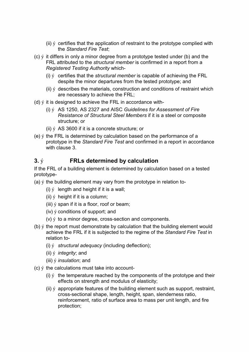
(c) ý it differs in only a minor degree from a prototype tested under (b) and the FRL attributed to the structural member is confirmed in a report from a Registered Testing Authority which-
(i) ý certifies that the structural member is capable of achieving the FRL despite the minor departures from the tested prototype; and
(ii) ý describes the materials, construction and conditions of restraint which are necessary to achieve the FRL;
(d) ý it is designed to achieve the FRL in accordance with-
(i) ý AS 1250, AS 2327 and AISC Guidelines for Assessment of Fire Resistance of Structural Steel Members if it is a steel or composite structure; or
(ii) ý AS 3600 if it is a concrete structure; or
(e) ý the FRL is determined by calculation based on the performance of a prototype in the Standard Fire Test and confirmed in a report in accordance with clause 3.
3. ý FRLs determined by calculation If the FRL of a building element is determined by calculation based on a tested prototype-
(a) ý the building element may vary from the prototype in relation to-
(i) ý length and height if it is a wall;
(ii) ý height if it is a column;
(iii) ý span if it is a floor, roof or beam;
(iv) ý conditions of support; and
(v) ý to a minor degree, cross-section and components.
(b) ý the report must demonstrate by calculation that the building element would achieve the FRL if it is subjected to the regime of the Standard Fire Test in relation to-
(i) ý structural adequacy (including deflection);
(ii) ý integrity; and
(iii) ý insulation; and
(c) ý the calculations must take into account-
(i) ý the temperature reached by the components of the prototype and their effects on strength and modulus of elasticity;
(ii) ý appropriate features of the building element such as support, restraint, cross-sectional shape, length, height, span, slenderness ratio, reinforcement, ratio of surface area to mass per unit length, and fire protection;

(iii) ý features of the prototype that influenced its performance in the Standard Fire Test although these features may not have been taken into account in the design for dead and live load;
(iv) ý features of the conditions of test, the manner of support and the position of the prototype during the test, that might not be reproduced in the building element if it is exposed to fire; and
(v) ý the design load of the building element in comparison with the tested prototype.
4. ý Interchangeable materials (a) ý Concrete and plaster - An FRL achieved with any material of Group A, B,
C, D or E as an ingredient in concrete or plaster, applies equally when any other material of the same group is used in the same proportions:
Group A: Any portland cement. ý
Group B: Any lime. ý
Group C: Any dense sand. ý
Group D: Any dense calcareous aggregate, including any ý limestone or any calcareous gravel.
Group E: Any dense siliceous aggregate, including any basalt, diorite, dolerite, granite, granodiorite or trachyte.
(b) ý Perlite and vermiculite - An FRL achieved with either gypsum-perlite plaster or gypsum-vermiculite plaster applies equally for both plasters.
5. ý Columns covered with lightweight construction (a) ý Protection against injury - If the fire-resisting covering of a steel column is
lightweight construction-
(i) ý the covering must be protected by steel or other suitable material if the column is liable to damage from the movement of vehicles, materials or equipment; and
(ii) ý the voids must be filled solid with non-combustible material to a height of not less than 1.2 m above the floor to prevent indenting if the covering is not in continuous contact with the column; and
(b) ý Sealing at floor level - A plug of non-combustible material must seal all voids at each floor level, including the voids between the column and its covering if-
(i) ý a steel column extends through 2 or more storeys; and
(ii) ý the fire-resisting covering is not in continuous contact with the column.

Table 1: FRLs DEEMED TO BE ACHIEVED BY CERTAIN BUILDING ELEMENTS ý BUILDING THICKNESS OF PRINCIPAL MATERIAL (mm) ANNEXURE ELEMENT REFERENCE
Clause No.
60/60/60 90/90/90 120/120/120 180/180/180 240/240/240
WALL
Masonry
Ashlar - - - - 300 1,2,6,7
Calcium silicate 70 90 110 135 160 1,3,4,5,7
Concrete with a material density in kg/m3 of-
1600 or more- 80 100 120 150 180 1,3,4,5,7
less than 1600- 70 90 110 135 160 1,3,4,5,7
Fired clay (incl 90 110 130 160 190 1,3,4,5,7 terracotta)
Concrete
No-fines - - - 150 170 1,6,7
Prestressed see 2(d)(ii) of this Specification
Reinforced see 2(d)(ii) of this Specification
Un-reinforced - - - 150 170 1,6,7
Solid gypsum blocks 75 90 100 110 125 1,6,7
Gypsum-perlite, Gypsum vermiculite-plaster on metal lath and channel
50 50 65 - - 1,6,8
CONCRETE COLUMN Concrete Prestressed see 2(d)(ii) of this Specification Reinforced see 2(d)(ii) of this Specification
HOT-ROLLED STEEL COLUMN (incl. a fabricated column) exposed on no more than 3 sides:
Fire protection of Concrete - Cast in-situ-loadbearing 25 30 40 55 75 9,10,12,13
non-loadbearing-unplastered 25 30 40 50 65 9,10,12,13
plastered 13 mm- 25 25 30 40 50 1,7,9,10,12,13
Gypsum - Cast in-situ - - - - 50 9,10,12,13
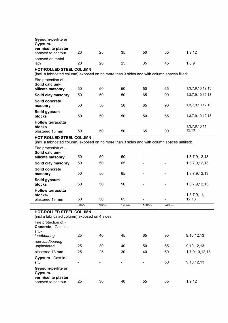
Gypsum-perlite or Gypsum-vermiculite plaster sprayed to contour 20 25 35 50 55 1,9,12
sprayed on metal lath 20 20 25 35 45 1,8,9
HOT-ROLLED STEEL COLUMN (incl. a fabricated column) exposed on no more than 3 sides and with column spaces filled:
Fire protection of -Solid calcium-silicate masonry 50 50 50 50 65 1,3,7,9,10,12,13
Solid clay masonry 50 50 50 65 90 1,3,7,9,10,12,13
Solid concrete masonry 50 50 50 65 90 1,3,7,9,10,12,13
Solid gypsum blocks 50 50 50 50 65 1,3,7,9,10,12,13
Hollow terracotta blocks 1,3,7,9,10,11,
plastered 13 mm 50 50 50 65 90 12,13
HOT-ROLLED STEEL COLUMN (incl. a fabricated column) exposed on no more than 3 sides and with column spaces unfilled:
Fire protection of -Solid calcium-silicate masonry 50 50 50 - - 1,3,7,9,12,13
Solid clay masonry 50 50 65 - - 1,3,7,9,12,13
Solid concrete masonry 50 50 65 - - 1,3,7,9,12,13
Solid gypsum blocks 50 50 50 - - 1,3,7,9,12,13
Hollow terracotta blocks- 1,3,7,9,11, plastered 13 mm 50 50 65 - - 12,13
60/-/- 90/-/- 120/-/- 180/-/- 240/-/-
HOT-ROLLED STEEL COLUMN (incl a fabricated column) exposed on 4 sides:
Fire protection of -Concrete - Cast in-situ-loadbearing 25 40 45 65 90 9,10,12,13
non-loadbearing-unplastered 25 30 40 50 65 9,10,12,13
plastered 13 mm 25 25 30 40 50 1,7,9,10,12,13
Gypsum - Cast in-situ - - - - 50 9,10,12,13
Gypsum-perlite or Gypsum-vermiculite plaster sprayed to contour 25 30 40 55 65 1,9,12
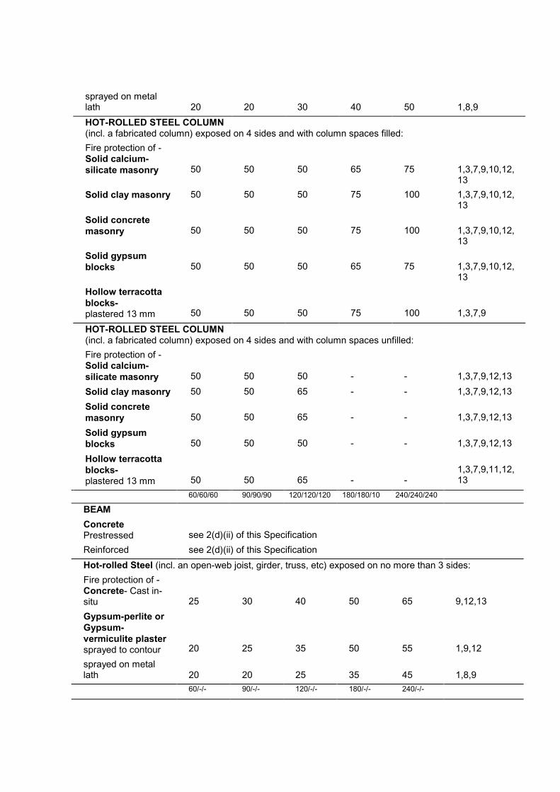
sprayed on metal lath 20 20 30 40 50 1,8,9
HOT-ROLLED STEEL COLUMN (incl. a fabricated column) exposed on 4 sides and with column spaces filled:
Fire protection of -Solid calcium-silicate masonry 50 50 50 65 75 1,3,7,9,10,12,
13
Solid clay masonry 50 50 50 75 100 1,3,7,9,10,12, 13
Solid concrete masonry 50 50 50 75 100 1,3,7,9,10,12,
13
Solid gypsum blocks 50 50 50 65 75 1,3,7,9,10,12,
13
Hollow terracotta blocks-plastered 13 mm 50 50 50 75 100 1,3,7,9
HOT-ROLLED STEEL COLUMN (incl. a fabricated column) exposed on 4 sides and with column spaces unfilled:
Fire protection of -Solid calcium-silicate masonry 50 50 50 - - 1,3,7,9,12,13
Solid clay masonry 50 50 65 - - 1,3,7,9,12,13
Solid concrete masonry 50 50 65 - - 1,3,7,9,12,13
Solid gypsum blocks 50 50 50 - - 1,3,7,9,12,13
Hollow terracotta blocks-plastered 13 mm 50 50 65 - -
1,3,7,9,11,12, 13
60/60/60 90/90/90 120/120/120 180/180/10 240/240/240
BEAM
Concrete Prestressed see 2(d)(ii) of this Specification
Reinforced see 2(d)(ii) of this Specification
Hot-rolled Steel (incl. an open-web joist, girder, truss, etc) exposed on no more than 3 sides:
Fire protection of -Concrete- Cast in-situ 25 30 40 50 65 9,12,13
Gypsum-perlite or Gypsum-vermiculite plaster sprayed to contour 20 25 35 50 55 1,9,12
sprayed on metal lath 20 20 25 35 45 1,8,9
60/-/- 90/-/- 120/-/- 180/-/- 240/-/-
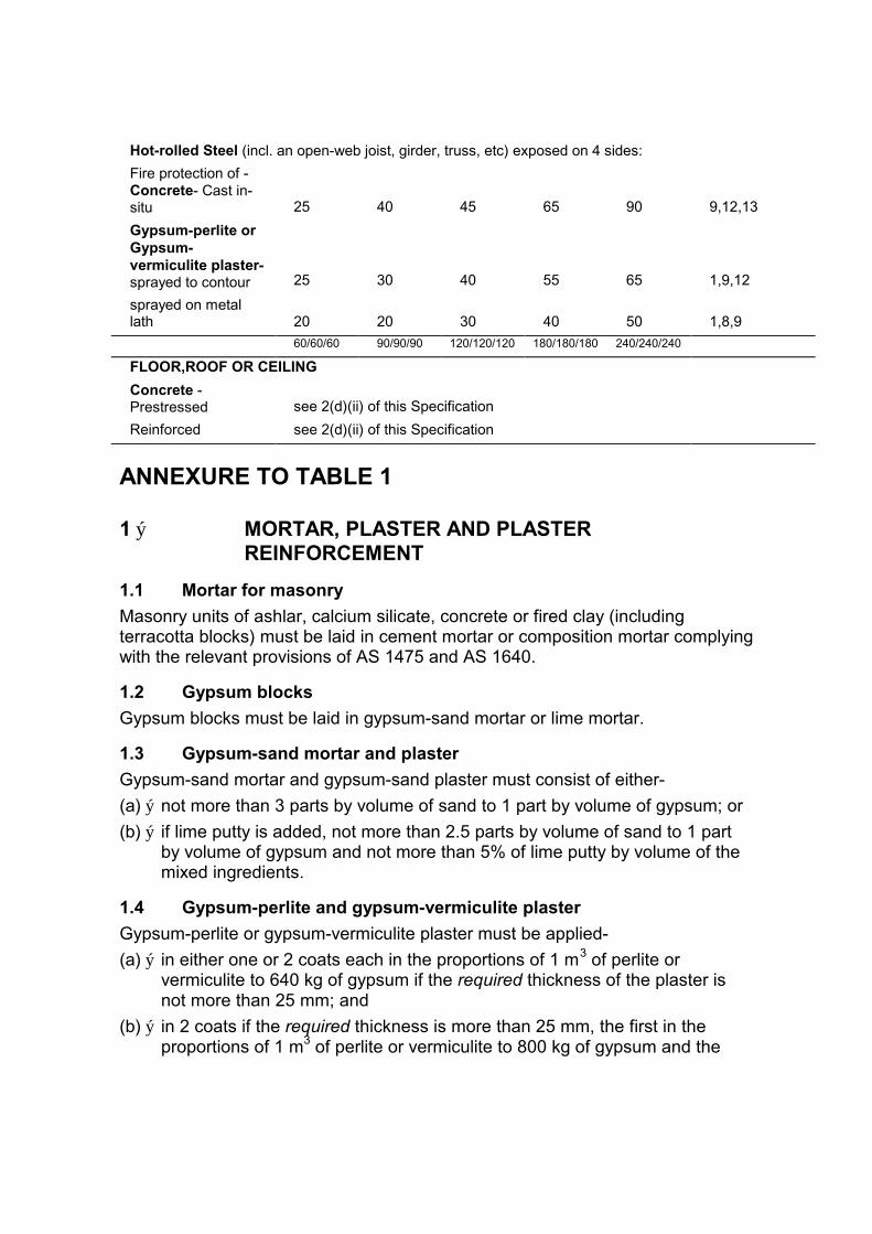
Hot-rolled Steel (incl. an open-web joist, girder, truss, etc) exposed on 4 sides:
Fire protection of -Concrete- Cast in-situ 25 40 45 65 90 9,12,13
Gypsum-perlite or Gypsum-vermiculite plaster-sprayed to contour 25 30 40 55 65 1,9,12
sprayed on metal lath 20 20 30 40 50 1,8,9
60/60/60 90/90/90 120/120/120 180/180/180 240/240/240
FLOOR,ROOF OR CEILING
Concrete -Prestressed see 2(d)(ii) of this Specification
Reinforced see 2(d)(ii) of this Specification
ANNEXURE TO TABLE 1
1 ý MORTAR, PLASTER AND PLASTER REINFORCEMENT
1.1 Mortar for masonry
Masonry units of ashlar, calcium silicate, concrete or fired clay (including terracotta blocks) must be laid in cement mortar or composition mortar complying with the relevant provisions of AS 1475 and AS 1640.
1.2 Gypsum blocks
Gypsum blocks must be laid in gypsum-sand mortar or lime mortar.
1.3 Gypsum-sand mortar and plaster
Gypsum-sand mortar and gypsum-sand plaster must consist of either-
(a) ý not more than 3 parts by volume of sand to 1 part by volume of gypsum; or
(b) ý if lime putty is added, not more than 2.5 parts by volume of sand to 1 part by volume of gypsum and not more than 5% of lime putty by volume of the mixed ingredients.
1.4 Gypsum-perlite and gypsum-vermiculite plaster
Gypsum-perlite or gypsum-vermiculite plaster must be applied-
(a) ý in either one or 2 coats each in the proportions of 1 m3 of perlite or vermiculite to 640 kg of gypsum if the required thickness of the plaster is not more than 25 mm; and
(b) ý in 2 coats if the required thickness is more than 25 mm, the first in the proportions of 1 m3 of perlite or vermiculite to 800 kg of gypsum and the
second in the proportions of 1 m3 of perlite or vermiculite to 530 kg of gypsum.
1.5 Plaster of cement and sand or cement, lime and sand
Plaster prescribed in Table 1 must consist of-
(a) ý cement and sand or cement, lime and sand; and
(b) ý may be finished with gypsum, gypsum-sand, gypsum-perlite or gypsum-vermiculite plaster or with lime putty.
1.6 Plaster reinforcement
If plaster used as fire protection on walls is more than 19 mm thick-
(a) ý it must be reinforced with expanded metal lath that-
(i) ý has a mass per unit area of not less than 1.84 kg/m2;
(ii) ý has not fewer than 98 meshes per metre; and
(iii) ý is protected against corrosion by galvanising or other suitable method; or
(b) ý it must be reinforced with13 mm x 13 mm x 0.7 mm galvanised steel wire mesh; and
(c) ý the reinforcement must be securely fixed at a distance from the face of the wall of not less than 1/3 of the total thickness of the plaster.
2 ý ASHLAR STONE MASONRY Ashlar masonry must not be used in a part of the building containing more than 2 storeys, and must not be of-
(a) ý aplite, granite, granodiorite, quartz dacite, quartz diorite, quartz porphyrite or quartz porphyry;
(b) ý conglomerate, quartzite or sandstone;
(c) ý chert or flint; or
(d) ý limestone or marble.
3 ý DIMENSIONS OF MASONRY The thicknesses of masonry of calcium-silicate, concrete and fired clay are calculated as follows:
3.1 Solid units
For masonry in which the amount of perforation or coring of the units does not exceed 25% by volume (based on the overall rectangular shape of the unit) the thickness of the wall must be calculated from the manufacturing dimensions of the units and the specified thickness of the joints between them as appropriate.
3.2 Hollow units
For masonry in which the amount of perforation or coring of the units exceeds 25% by volume (based on the overall rectangular shape of the unit) the thickness of the wall must be calculated from the equivalent thicknesses of the units and the specified thickness of the joints between them as appropriate.
3.3 Equivalent thickness
The equivalent thickness of a masonry unit is calculated by dividing the net volume by the area of one vertical face.
3.4 Cavity walls
The thickness of a cavity wall is the sum of the thicknesses of the leaves determined in accordance with 3.1 and/or 3.2 as appropriate.
3.5 Cavity walls of different materials
If the 2 leaves of a cavity wall are of units of different type, the thickness required is that listed for the less fire-resistant material (ie. the greater thickness).
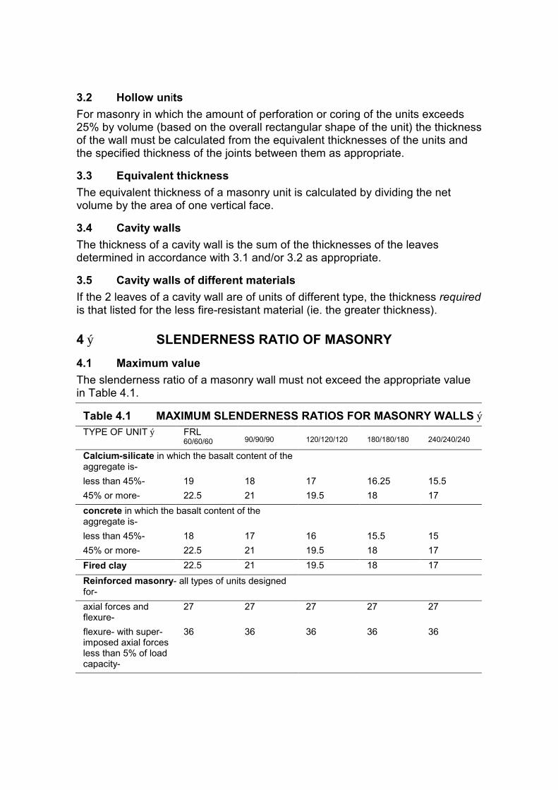
4 ý SLENDERNESS RATIO OF MASONRY
4.1 Maximum value
The slenderness ratio of a masonry wall must not exceed the appropriate value in Table 4.1.
Table 4.1 MAXIMUM SLENDERNESS RATIOS FOR MASONRY WALLS ý TYPE OF UNIT ý FRL
60/60/60 90/90/90 120/120/120 180/180/180 240/240/240
Calcium-silicate in which the basalt content of the aggregate is-
less than 45%- 19 18 17 16.25 15.5
45% or more- 22.5 21 19.5 18 17
concrete in which the basalt content of the aggregate is-
less than 45%- 18 17 16 15.5 15
45% or more- 22.5 21 19.5 18 17
Fired clay 22.5 21 19.5 18 17
Reinforced masonry- all types of units designed for-
axial forces and 27 27 27 27 27 flexure-
flexure- with super- 36 36 36 36 36 imposed axial forces less than 5% of load capacity-
4.2 Calculation
The slenderness ratio of a masonry wall is calculated in accordance with AS 1640 except that it must be based exclusively on effective height and the effective thickness to be adopted is-
(a) ý for single leaf walls - the overall thickness of the wall based on the manufacturing thicknesses of the units and the specified thickness of the joints between them as appropriate;
(b) ý for cavity walls with neither leaf loadbearing or both leaves loadbearing, whichever is the greater of-
(i) ý 2/3 the sum of the individual thicknesses of the leaves determined according to (a); or
(ii) ý the thickness of the thicker leaf (similarly determined),
(c) ý for cavity walls with one leaf loadbearing - the thickness of the loadbearing leaf determined according to (a).
4.3 Cavity walls of different materials
If the 2 leaves of a cavity wall are of units of different type, the slenderness ratio is-
(a) ý if the thickness is determined by 4.2(b)(i) - the slenderness ratio applicable to the less fire-resistant material (that with the smaller maximum permissable slenderness ratio in Table 4.1); or
(b) ý if the thickness is determined by 4.2(b)(ii) or (c) - the slenderness ratio of the leaf that determines the thickness.
5 ý PROTECTION TO MASONRY REINFORCEMENT In a building element of reinforced masonry designed for fire-resistance, the distance from the surface of the element to the surface of the reinforcement must not be less than-
(a) ý for FRL 60/60/60 or 90/90/90 - 30 mm;
(b) ý for FRL 120/120/120 - 40 mm;
(c) ý for FRL 180/180/180 - 55 mm; and
(d) ý for FRL 240/240/240 - 65 mm.
6 ý HEIGHT-TO-THICKNESS RATIO OF CERTAIN WALLS
The ratio of height between lateral supports to overall thickness of a wall of ashlar, no-fines concrete, unreinforced concrete, solid gypsum blocks, gypsum-perlite or gypsum-vermiculite plaster on metal lath and channel, must not exceed-
(a) ý 20 for a loadbearing wall; or
(b) ý 27 for a non-loadbearing wall.
7 INCREASE IN THICKNESS BY PLASTERING
7.1 General
The tabulated thicknesses are those of the principal material. They do not include the thickness of plaster which must be additional to the listed thickness of the material to which it is applied.
7.2 Walls
If a wall of masonry, solid gypsum blocks or concrete is plastered on both sides to an equal thickness, the thickness of the wall for the purposes of Table 1 (but not for the purposes of Annexure Clause 6) may be increased by the following proportions of the thickness of the plaster on one side:
(a) ý For fired clay masonry and for concrete masonry in which the aggregate is of a density in excess of 1800 kg/m3 100%
(b) ý For calcium-silicate masonry and for concrete masonry in which the aggregate is oaf a density between 1600 and 1800 kg/m3 85%
(c) ý For concrete masonry in which the aggregate is of a density less than 1600 kg/m3 75%
8 ý GYPSUM-PERLITE OR GYPSUM-VERMICULITE PLASTER ON METAL LATH
8.1 Walls
In walls fabricated of gypsum-perlite or gypsum-vermiculite plaster on metal lath and channel-
(a) ý the lath must be securely wired to each side of 19 mm x 0.44 kg/m steel channels (used as studs) spaced at not more than 400 mm centres; and
(b) ý the gypsum-perlite or gypsum-vermiculite plaster must be applied symmetrically to each exposed side of the lath.
8.2 Columns
For the fire protection of steel columns with gypsum-perlite or gypsum-vermiculite on metal lath-
(a) ý the thickness of the plaster must be measured from the back of the lath;
(b) ý the lath must be fixed at not more than 600 mm centres vertically to steel furring channels, and-
(i) ý if the plaster is to be 35 mm thick or more - at least 12 mm clear of the column; or
(ii) ý if the plaster is to be less than 35 mm thick - at least 6 mm clear of the column; or
(c) ý the plaster may be applied to self-furring lath with furring dimples to hold it not less than 10 mm clear of the column.

8.3 Beams
For the fire protection of steel beams with gypsum-perlite or gypsum-vermiculite on metal lath-
(a) ý the lath must be fixed at not more than 600 mm centres to steel furring channels and at least 20 mm clear of the steel; and
(b) ý the thickness of the plaster must be measured from the back of the lath.
9 ý EXPOSURE OF COLUMNS AND BEAMS
9.1 Columns
A column incorporated in or in contact on one or more sides with a wall of solid masonry or concrete at least 100 mm thick may be considered to be exposed to fire on no more than 3 sides.
9.2 Beams
A beam, open-web joist, girder or truss in direct and continuous contact with a concrete slab or a hollow block floor or roof may be considered to be exposed to fire on no more than 3 sides.
10 ý FILLING OF COLUMN SPACES If steel columns are deemed to have FRLs of more than 120/120/120 or more than 120/-/-, the spaces between the fire-protective material and the steel (and any re-entrant parts of the column itself) must be filled solid with a fire-protective material like concrete, gypsum or grout.
11 ý HOLLOW TERRACOTTA BLOCKS The proportion of cored holes or perforations in a hollow terracotta block (based on the overall rectangular volume of the unit) must not exceed-
(a) ý for blocks up to 75 mm thick 35%
(b) ý for blocks more than 75 mm but not more than 100 mm thick 40%
(c) ý for blocks more than 100 mm 50%
12 ý REINFORCEMENT FOR COLUMN AND BEAM PROTECTION
12.1 Masonry
Masonry of calcium-silicate, fired clay and concrete for the protection of steel columns must have steel-wire or mesh reinforcement in every second course and lapped at the corners.

12.2 Gypsum blocks and hollow terracotta blocks
Gypsum blocks and hollow terracotta blocks for the protection of steel columns must have steel-wire or mesh reinforcement in every course and lapped at corners.
12.3 Structural concrete and poured gypsum
If a steel column or a steel beam is to be protected with structural concrete or poured gypsum-
(a) ý the concrete or gypsum must be reinforced with steel-wire mesh or steel-wire binding placed about 20 mm from its outer surface; and
(b) ý for concrete or gypsum less than 50 mm thick, the steel wire must be-
(i) ý at least 3.15 mm in diameter; and
(ii) ý spaced at not more than 100 mm vertically; or
(c) ý for concrete or gypsum not less than 50 mm thick, the steel wire must be either-
(i) ý of a diameter and spacing in accordance with (b); or
(ii) ý at least 5 mm in diameter and spaced at not more than 150 mm vertically.
12.4 Gypsum-perlite or gypsum-vermiculite plaster sprayed to contour
(a) ý If a steel column or steel beam is protected with either gypsum-perlite or gypsum-vermiculite plaster sprayed to contour and the construction falls within the limits of Table 12.4, the plaster must be reinforced with-
(i) ý expanded metal lath complying with 1.6; or
(ii) ý galvanised steel wire mesh complying with 1.6.
(b) ý The reinforcement must be placed at a distance from the face of the plaster of at least 1/3 of the thickness of the plaster and must be securely fixed to the column or beam at intervals of not more than the relevant listing in Table 12.4.
Table 11.4 REINFORCEMENT OF GYPSUM-PERLITE OR GYPSUM-VERMICULITE PLASTER SPRAYED TO CONTOUR
SURFACE TO BE ý REINFORCEMENT MAX SPACING OF PROTECTED ý REQUIRED IF SMALLER FIXINGS OF THE MESH
DIMENSION OF TO SURFACE (mm) SURFACE EXCEEDS (mm)
Members with H or I cross-section:
Vertical- 450 450
Non-vertical- 300 300
Underside- 300 300
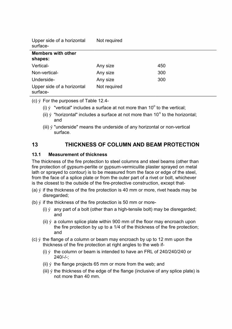
Upper side of a horizontal Not required surface-
Members with other shapes:
Vertical- Any size 450
Non-vertical- Any size 300
Underside- Any size 300
Upper side of a horizontal Not required surface-
(c) ý For the purposes of Table 12.4-
(i) ý "vertical" includes a surface at not more than 10o to the vertical;
(ii) ý "horizontal" includes a surface at not more than 10o to the horizontal; and
(iii) ý "underside" means the underside of any horizontal or non-vertical surface.
13 THICKNESS OF COLUMN AND BEAM PROTECTION
13.1 Measurement of thickness
The thickness of the fire protection to steel columns and steel beams (other than fire protection of gypsum-perlite or gypsum-vermiculite plaster sprayed on metal lath or sprayed to contour) is to be measured from the face or edge of the steel, from the face of a splice plate or from the outer part of a rivet or bolt, whichever is the closest to the outside of the fire-protective construction, except that-
(a) ý if the thickness of the fire protection is 40 mm or more, rivet heads may be disregarded;
(b) ý if the thickness of the fire protection is 50 mm or more-
(i) ý any part of a bolt (other than a high-tensile bolt) may be disregarded; and
(ii) ý a column splice plate within 900 mm of the floor may encroach upon the fire protection by up to a 1/4 of the thickness of the fire protection; and
(c) ý the flange of a column or beam may encroach by up to 12 mm upon the thickness of the fire protection at right angles to the web if-
(i) ý the column or beam is intended to have an FRL of 240/240/240 or 240/-/-;
(ii) ý the flange projects 65 mm or more from the web; and
(iii) ý the thickness of the edge of the flange (inclusive of any splice plate) is not more than 40 mm.

SPECIFICATION A2.4 EARLY FIRE HAZARD TEST FOR ASSEMBLIES
1. ý Scope This Specification sets out the procedures for determining the Early Fire hazard Indices of components and assemblies.
2. ý Form of test tests carried out in accordance with AS 1530.
3. ý Test specimens Test specimens must incorporate-
(a) ý all types of joints; and
(b) ý all types of perforations, recesses or the like for pipes, light switches or other fittings, which are proposed to be used for the member or assembly of members in the building.
4. ý Concession Clause 3 does not apply to joints, perforations, recesses or the like that are larger than those in the proposed application and have already been tested in the particular form of construction concerned and found to comply with the conditions of test.
5. ý Smaller specimens permitted A testing laboratory may carry out the test at pilot scale if a specimen (which must be not less than 900 mm0 will adequately represent the proposed construction in the building, but the results of that test do not apply to construction larger than limits defined by the laboratory conducting the pilot examination.
**********************************************************************************

SECTION B STRUCTURE
CONTENTS
B1 Structural Provisions B1.1 General Requirements
B1.2 Loads
B1.3 Construction deemed-to-satisfy
B2 Demolition No provisions
OBJECTIVES A building must be so designed and constructed that the following objectives are fulfilled:
Part B1 Structural Provisions All loads, internal actions, material properties and foundation conditions that significantly affect structural sufficiency or serviceability must be taken into account in the construction of a building or other structure.
Part B2 Demolition Procedures and methods of demolition must be adequate to prevent injury to persons and avoid damage to neighbouring property.
B1 Structural Provisions
B1.1 General requirements Materials, components and methods of construction used in a building or structure must be capable of sustaining at an acceptable level of safety and serviceability-
(a) ý the most adverse combination of loads (including combinations of loads that might result in a potential for progressive collapse); and
(b) other actions, ý
to which they may reasonably be subjected. ý
B1.2 Loads The loading requirements of B1.1 are satisfied if the building or structure can resist loads determined in accordance with the following:
(a) ý Dead, live and wind loads: AS 1170.1 and AS 1170.2.
(b) ý Seismic loads: Buildings erected in earthquake areas- AS 2121.
(c) ý Snow loads: The roof of buildings located in an alpine area constructed to withstand snow loading of-
(i) ý not less than 5 kPa if the slope of the roof is less than 22o to the horizontal; or
(ii) ý not less than 3 kPa if the slope is 22o or more.
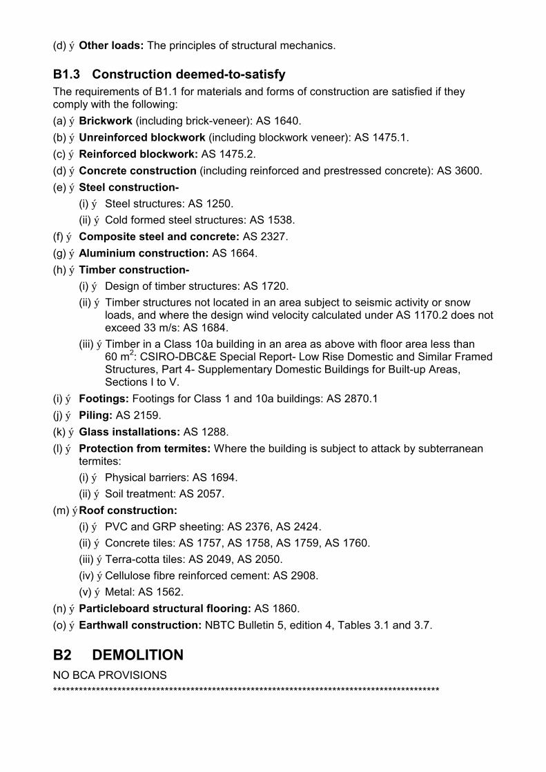
(d) ý Other loads: The principles of structural mechanics.
B1.3 Construction deemed-to-satisfy The requirements of B1.1 for materials and forms of construction are satisfied if they comply with the following:
(a) ý Brickwork (including brick-veneer): AS 1640.
(b) ý Unreinforced blockwork (including blockwork veneer): AS 1475.1.
(c) ý Reinforced blockwork: AS 1475.2.
(d) ý Concrete construction (including reinforced and prestressed concrete): AS 3600.
(e) ý Steel construction-
(i) ý Steel structures: AS 1250.
(ii) ý Cold formed steel structures: AS 1538.
(f) ý Composite steel and concrete: AS 2327.
(g) ý Aluminium construction: AS 1664.
(h) ý Timber construction-
(i) ý Design of timber structures: AS 1720.
(ii) ý Timber structures not located in an area subject to seismic activity or snow loads, and where the design wind velocity calculated under AS 1170.2 does not exceed 33 m/s: AS 1684.
(iii) ý Timber in a Class 10a building in an area as above with floor area less than 60 m2: CSIRO-DBC&E Special Report- Low Rise Domestic and Similar Framed Structures, Part 4- Supplementary Domestic Buildings for Built-up Areas, Sections I to V.
(i) ý Footings: Footings for Class 1 and 10a buildings: AS 2870.1
(j) ý Piling: AS 2159.
(k) ý Glass installations: AS 1288.
(l) ý Protection from termites: Where the building is subject to attack by subterranean termites:
(i) ý Physical barriers: AS 1694.
(ii) ý Soil treatment: AS 2057.
(m) ýRoof construction:
(i) ý PVC and GRP sheeting: AS 2376, AS 2424.
(ii) ý Concrete tiles: AS 1757, AS 1758, AS 1759, AS 1760.
(iii) ý Terra-cotta tiles: AS 2049, AS 2050.
(iv) ý Cellulose fibre reinforced cement: AS 2908.
(v) ý Metal: AS 1562.
(n) ý Particleboard structural flooring: AS 1860.
(o) ý Earthwall construction: NBTC Bulletin 5, edition 4, Tables 3.1 and 3.7.
B2 DEMOLITION NO BCA PROVISIONS
******************************************************************************************

SECTION C FIRE RESISTANCE
CONTENTS
C1 Fire Resistance and Stability C1.1 Type of construction required
C1.2 Calculation of rise in storeys
C1.3 Buildings of multiple classification
C1.4 Mixed Types of construction
C1.5 Two storey Class 2 or 3 buildings
C1.6 Class 4 parts of buildings
C1.7 Open spectator stands and indoor sports stadiums
C1.8 Lightweight construction
C1.9 Class 1 and 10 buildings
C1.10 Early Fire Hazard Indices
C2 Compartmentation and Separation C2.1 Application
C2.2 General floor area limitations
C2.3 Large isolated buildings
C2.4 Requirements for open spaces and vehicular access
C2.5 Class 9a buildings
C2.6 Vertical separation of openings in external walls
C2.7 Separation by fire walls
C2.8 Separation of classifications in the same storey
C2.9 Separation of classifications in different storeys
C2.10 Separation of lift shafts
C2.11 Stairways and lifts in one shaft
C2.12 Separation of equipment
C2.13 Electricity substations
C3 Protection of Openings C3.1 Application of Part
C3.2 Protection of openings in external walls
C3.3 Separation of openings in different fire compartments
C3.4 Acceptable methods of protection
C3.5 Doorways in fire walls
C3.6 Sliding fire doors
C3.7 Protection of doorways in horizontal exits
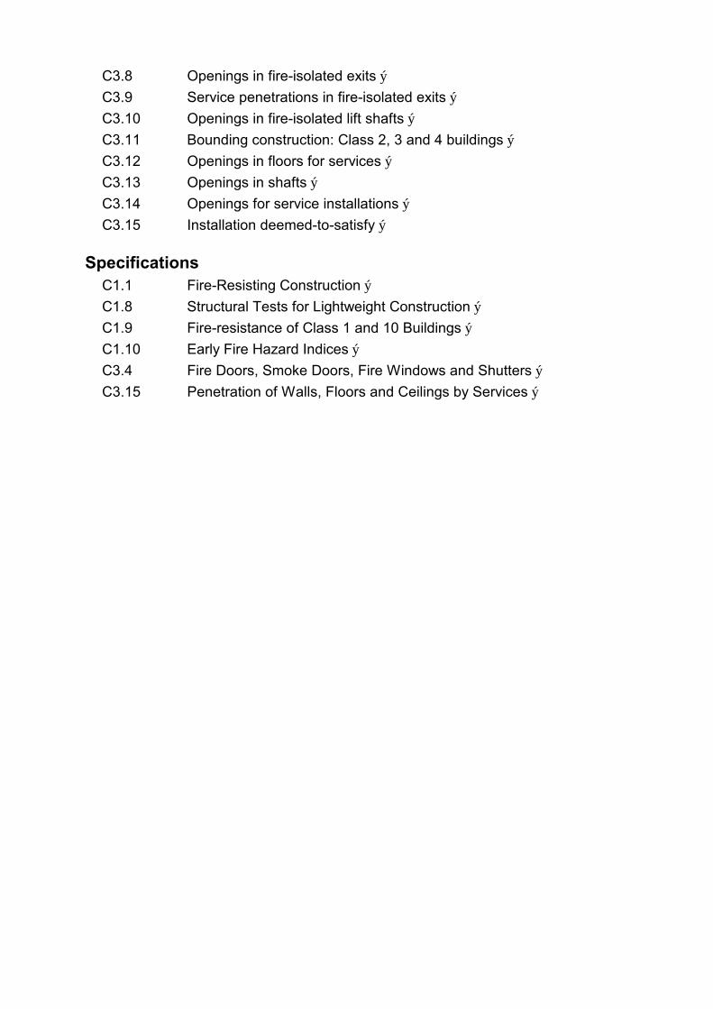
C3.8 Openings in fire-isolated exits ý
C3.9 Service penetrations in fire-isolated exits ý
C3.10 Openings in fire-isolated lift shafts ý
C3.11 Bounding construction: Class 2, 3 and 4 buildings ý
C3.12 Openings in floors for services ý
C3.13 Openings in shafts ý
C3.14 Openings for service installations ý
C3.15 Installation deemed-to-satisfy ý
Specifications C1.1 Fire-Resisting Construction ý
C1.8 Structural Tests for Lightweight Construction ý
C1.9 Fire-resistance of Class 1 and 10 Buildings ý
C1.10 Early Fire Hazard Indices ý
C3.4 Fire Doors, Smoke Doors, Fire Windows and Shutters ý
C3.15 Penetration of Walls, Floors and Ceilings by Services ý
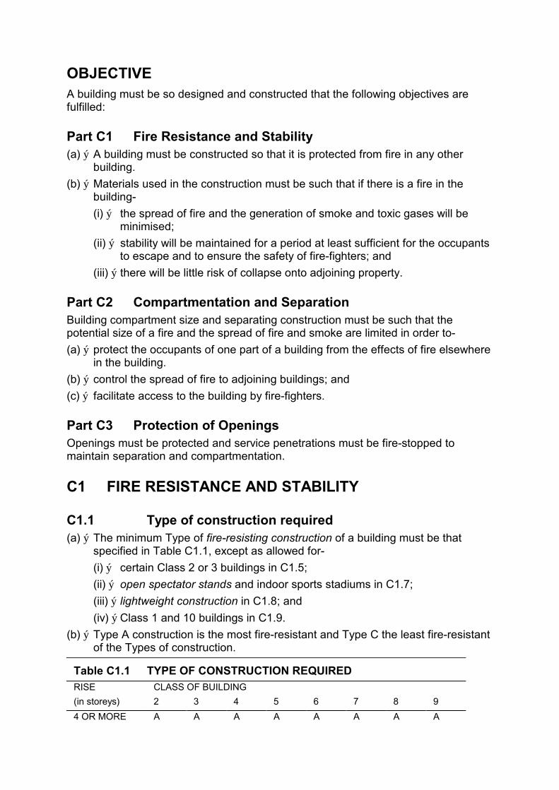
OBJECTIVE A building must be so designed and constructed that the following objectives are fulfilled:
Part C1 Fire Resistance and Stability (a) ý A building must be constructed so that it is protected from fire in any other
building.
(b) ý Materials used in the construction must be such that if there is a fire in the building-
(i) ý the spread of fire and the generation of smoke and toxic gases will be minimised;
(ii) ý stability will be maintained for a period at least sufficient for the occupants to escape and to ensure the safety of fire-fighters; and
(iii) ý there will be little risk of collapse onto adjoining property.
Part C2 Compartmentation and Separation Building compartment size and separating construction must be such that the potential size of a fire and the spread of fire and smoke are limited in order to-
(a) ý protect the occupants of one part of a building from the effects of fire elsewhere in the building.
(b) ý control the spread of fire to adjoining buildings; and
(c) ý facilitate access to the building by fire-fighters.
Part C3 Protection of Openings Openings must be protected and service penetrations must be fire-stopped to maintain separation and compartmentation.
C1 FIRE RESISTANCE AND STABILITY
C1.1 Type of construction required (a) ý The minimum Type of fire-resisting construction of a building must be that
specified in Table C1.1, except as allowed for-
(i) ý certain Class 2 or 3 buildings in C1.5;
(ii) ý open spectator stands and indoor sports stadiums in C1.7;
(iii) ý lightweight construction in C1.8; and
(iv) ý Class 1 and 10 buildings in C1.9.
(b) ý Type A construction is the most fire-resistant and Type C the least fire-resistant of the Types of construction.
Table C1.1 TYPE OF CONSTRUCTION REQUIRED RISE CLASS OF BUILDING
(in storeys) 2 3 4 5 6 7 8 9
4 OR MORE A A A A A A A A

3 A A B B B B B B
2 B B C C C C C C
1 C C C C C C C C
Notes:
1. See C1.6 for requirements for Class 4 parts of buildings.
2. See Specification C1.1 for details of Types A, B and C construction.
C1.2 Calculation of rise in storeys In calculating the rise in storeys-
(a) ý in a building of Class 7 or 8, a storey that has an average internal height of more than 6 m is counted as-
(i) ý one storey if it is the only storey above the ground; or
(ii) ý 2 storeys in any other case; and
(b) ý a storey is not counted if-
(i) ý it is situated at the top of the building and contains only service units or equipment; or
(ii) ý it is situated partly below the finished ground and the underside of the ceiling is not more than 1 m above the average finished level of the ground at the external wall, or if the external wall is more than 12 m long, the average for the 12 m part where the ground is lowest.
C1.3 Buildings of multiple classification Subject to C1.4, in a building of multiple classifications, the Type of fire-resisting construction required is the Type resulting from the application of Table C1.1 at each storey on the basis that-
(a) ý a classification applying to the particular storey applies also to the storeys vertically below it; and
(b) ý the particular storey and those vertically below it comprise an entire building.
C1.4 Mixed Types of construction A building may be of mixed Types of construction if no part of the building is supported by, or vertically over, a part of less fire-resisting Type.
C1.5 Two storey Class 2 or 3 buildings A building of Class 2 or 3, or a mixture of these Classes, having a rise of 2 storeys, may be of Type C construction if-
(a) ý each sole-occupancy unit and all other parts of the building are served by at least 2 exits in addition to any horizontal exit; or
(b) ý each sole-occupancy unit in the building has its own direct access to a road or open space and all other parts of the building are served by at least 2 exits in addition to any horizontal exit.
C1.6 Class 4 parts of buildings A Class 4 part of a building requires the same FRL for structural members and the same construction separating the Class 4 part from the remainder of the building as a Class 2 part in similar circumstances.
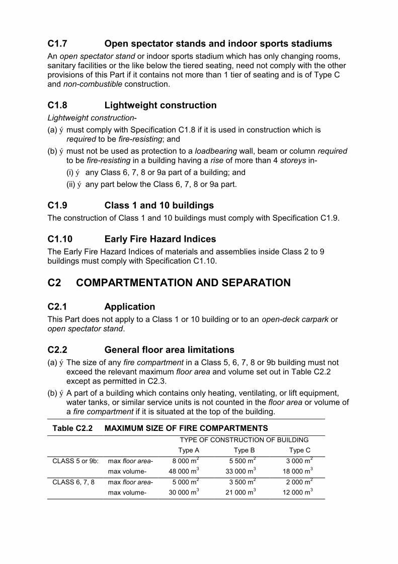
C1.7 Open spectator stands and indoor sports stadiums An open spectator stand or indoor sports stadium which has only changing rooms, sanitary facilities or the like below the tiered seating, need not comply with the other provisions of this Part if it contains not more than 1 tier of seating and is of Type C and non-combustible construction.
C1.8 Lightweight construction Lightweight construction-
(a) ý must comply with Specification C1.8 if it is used in construction which is required to be fire-resisting; and
(b) ý must not be used as protection to a loadbearing wall, beam or column required to be fire-resisting in a building having a rise of more than 4 storeys in-
(i) ý any Class 6, 7, 8 or 9a part of a building; and
(ii) ý any part below the Class 6, 7, 8 or 9a part.
C1.9 Class 1 and 10 buildings The construction of Class 1 and 10 buildings must comply with Specification C1.9.
C1.10 Early Fire Hazard Indices The Early Fire Hazard Indices of materials and assemblies inside Class 2 to 9 buildings must comply with Specification C1.10.
C2 COMPARTMENTATION AND SEPARATION
C2.1 Application This Part does not apply to a Class 1 or 10 building or to an open-deck carpark or open spectator stand.
C2.2 General floor area limitations (a) ý The size of any fire compartment in a Class 5, 6, 7, 8 or 9b building must not
exceed the relevant maximum floor area and volume set out in Table C2.2 except as permitted in C2.3.
(b) ý A part of a building which contains only heating, ventilating, or lift equipment, water tanks, or similar service units is not counted in the floor area or volume of a fire compartment if it is situated at the top of the building.
Table C2.2 MAXIMUM SIZE OF FIRE COMPARTMENTS TYPE OF CONSTRUCTION OF BUILDING
CLASS 5 or 9b: max floor area-
max volume-
Type A
8 000 m2
48 000 m3
Type B
5 500 m2
33 000 m3
Type C
3 000 m2
18 000 m3
CLASS 6, 7, 8 max floor area- 5 000 m2 3 500 m2 2 000 m2
max volume- 30 000 m3 21 000 m3 12 000 m3

C2.3 Large isolated buildings The floor area of a fire compartment in a building may exceed that specified in Table C2.2 where-
(a) ý the floor area does not exceed 18 000 m2 if-
(i) ý the building is Class 7 or 8, it contains not more than 2 storeys and an open space complying with C2.4(a) not less than 18 m wide is provided around the building; or
(ii) ý the building is of any Class and is protected throughout with a sprinkler system and perimeter vehicular access complying with C2.4(b) is provided; or
(b) ý the floor area exceeds 18 000 m2 if-
(i) ý the building is protected throughout with a sprinkler system and perimeter vehicular access complying with C2.4(b) is provided; and
(ii) ý if the ceiling height of the fire compartment is not more than 12 m, it has a smoke exhaust system in accordance with Specification E2.5 or smoke-and-heat vents and the space below the roof is divided into compartments in accordance with AS 2665; and
(iii) ý if the ceiling height is more than 12 m, it has a smoke exhaust system in accordance with Specification E2.6; and
(c) ý if more than one building is on the allotment-
(i) ý each building must comply with (a) or (b); or
(ii) ý if the buildings are closer than 6 m to each other and no building is more than 45 m from the required vehicular access, they are regarded as one building and collectively must comply with (a) or (b).
C2.4 Requirements for open spaces and vehicular access (a) ý An open space required by C2.3 must-
(i) ý be wholly within the allotment; and
(ii) ý include vehicular access in accordance with (b); and
(iii) ý be next to the boundaries of the allotment, and may include any road, river, or public place adjoining the allotment, but not the farthest 6 m of it; and
(iv) ý not be used for the storage or processing of materials; and
(v) ý not be built upon, except for guard houses and service structures (such as electricity substations and pump houses) which may encroach upon the width of the space if they do not unduly impede fire-fighting at any part of the perimeter of the allotment or unduly add to the risk of spread of fire to any building on an adjoining allotment.
(b) ý Wherever vehicular access is required by this Part-
(i) ý it must be capable of providing emergency vehicle access and passage from a public road; and
(ii) ý the vehicular access must have a minimum unobstructed width of 6 m and in no part be built upon or used for any purpose other than vehicular or pedestrian movement; and

(iii) ý if the building faces and is accessible from a public road, the road may be counted as providing vehicular access if the building is no further than 45 m from the road; and
(iv) ý reasonable pedestrian access from the vehicular access to the building must be provided; and
(v) ý the accessway must be of adequate load bearing capacity and unobstructed height to permit the operation and passage of Fire Brigade vehicles.
C2.5 Class 9a buildings In a Class 9a building-
(a) ý Floor areas more than 425 m2 must be divided into at least 2 parts by smoke-proof walls complying with (d);
(b) ý Ward areas with a floor area more than 850 m2 must be-
(i) ý divided into fire compartments with a floor area of not more than 1700 m2
and;
(ii) ý further subdivided into areas not more than 850 m2 in floor area by walls with an FRL of not less than 60/60/60 and further subdivided into not less than 2 parts by smoke-proof walls complying with (d); and
(c) ý parts of the building not being ward areas must be divided into fire compartments not exceeding 1700 m2 in floor area; and
(d) ý a wall required to be smoke-proof must-
(i) ý be non-combustible and extend to the underside of the floor above or of the roof covering;
(ii) ý only have doorways which are fitted with smoke doors complying with Specification C3.4 and which do not extend higher than 800 mm from the underside of an imperforate roof covering, floor or ceiling above it; and
(iii) ý not incorporate any other opening which is not smoke-proof; and
(e) ý Fire compartments must be separated from the remainder of the building by fire walls and-
(i) ý in Type A construction - floors and roof or ceiling as required in ý Specification C1.1; ý
(ii) ý in Type B construction - floors with an FRL of not less than 120/120/120; and
(iii) ý in Type C construction - floors with an FRL of not less than 90/90/90.
C2.6 Vertical separation of openings in external walls In a building which is required to be of Type A construction and does not have a sprinkler system (other than an open-deck carpark or an open spectator stand),if any part of a window or other opening in an external wall, (except openings within the same stairway) is situated above another opening in the srorey next below, the openings must be separated by-
(a) ý a spandrel which-
(i) ý is not less than 900 mm in height;
(ii) ý extends not less than 600 mm above the upper surface of the intervening floor; and

(iii) is of non-combustible material having an FRL not less than 60/60/60; or
(b) ý part of a curtain wall or panel wall that complies with (a); or
(c) ý construction that complies with (a) behind a curtain wall or panel wall and has any gaps packed with a non-combustible material that will withstand thermal expansion and structural movement of the walling without loss of seal; or
(d) ý a slab or other horizontal construction that-
(i) ý projects outwards from the external face of the wall not less than 1100 mm;
(ii) ý extends along the wall not less than 450 mm beyond the openings concerned; and
(iii) ý is non-combustible and has an FRL of not less than 60/60/60; or
(e) ý other constructtion which is as equally effective as (a), (b), (c) or (d).
C2.7 Separation by fire walls A part of a building separated from the remainder of the building by a fire wall is treated as a separate building if-
(a) ý the fire wall-
(i) ý extends through all storeys and spaces in the nature of storeys that are common to that part and any adjoining part of the building;
(ii) ý is carried through to the underside of the roof covering; and
(iii) ý has the relevant FRL prescribed by Specification C1.1 for each of the adjoining parts, and if these are different, the greater FRL; and
(b) ý any openings in a fire wall comply with Part C3; and
(c) ý timber purlins or other combustible material do not pass through or cross the fire wall; and
(d) ý where the roof of one of the adjoining parts is lower than the roof of the other part, the fire wall extends to the underside of-
(i) ý the covering of the higher roof, or not less than 6 m above the covering of the lower roof; or
(ii) ý the lower roof if it has an FRL not less than that of the fire wall and no openings closer than 3 m to any wall above the lower roof; or
(iii) ý the lower roof if its covering is non-combustible and the lower part has a sprinkler system,
or the design of the building must otherwise restrict the spread of fire from the lower part to the higher part.
C2.8 Separation of classifications in the same storey If a building has parts of different classifications located alongside one another in the same storey-
(a) ý each building element in that storey must have the higher FRL prescribed in Specification C1.1 for that element for the classifications concerned; or
(b) ý the parts must be separated in that storey by a fire wall with whichever is the greater of-
(i) ý an FRL of 90/90/90 if the parts are served in any storey by the same public corridor, public hallway, or the like; or
(ii) ý the higher FRL prescribed in Specification C1.1 for the classifications concerned.
C2.9 Separation of classifications in different storeys If parts of different classification are situated one above the other in adjoining storeys they must be separated as follows:
(a) ý Type A construction - The floor between the adjoining parts must have an FRL not less than that prescribed in Specification C1.1 for the classification of the lower storey.
(b) ý Type B or C construction (applicable only if one of the adjoining parts is of Class 2, 3 or 4) - The underside of the floor (including the sides and underside of any floor beams) must have a fire-protective covering.
C2.10 Separation of lift shafts Lifts connecting more than 2 storeys, or more than 3 storeys if the building is sprinklered, (other than lifts which are wholly within an atrium) must be separated from the remainder of the building by enclosure in a shaft in which-
(a) ý in a building required to be of Type A construction - the walls have the relevant FRL prescribed by Specification C1.1;
(b) ý in a building required to be of Type B construction- the walls are-
(i) ý in accordance with (a) if the shaft is loadbearing; or
(ii) ý of non-combustible construction if the shaft is non-loadbearing; and
(c) ý openings for lift landing doors and services are protected in accordance with Part C3.
C2.11 Stairways and lifts in one shaft A stairway and lift must not be in the same shaft if either the stairway or the lift is required to be in a fire-resisting shaft.
C2.12 Separation of equipment A wall having an FRL of not less than 120/120/120 must bound a room housing equipment comprising-
(a) ý lift motors and lift control panels;
(b) ý the main electrical switchboard in a building with an effective height of more than 25 m;
(c) ý required stair pressurising equipment; or
(d) ý boilers, emergency batteries, sprinkler valves, emergency generators or central smoke control plant, except-
(i) ý equipment located in a separate storey (or in the topmost storey) and separated from the remainder of the building by floor construction having an FRL of 120/120/120;
(ii) ý smoke control exhaust fans located in the air stream if they are ý constructed for high temperature operation in accordance with ý Specification E2.5; or ý
(iii) equipment that is otherwise adequately separated from the remainder of the building.

C2.13 Electricity substations If an electricity substation is situated within a building-
(a) ý it must be separated from any other part of the building by construction having an FRL of not less than 120/120/120;
(b) ý any doorways opening to any other part of the building must be protected with self-closing 120/120/30 fire doors; and
(c) ý electricity supply cables between a main and the substation, and between the substation and the main electrical switchboard, must be enclosed or otherwise protected by construction having an FRL of not less than 120/120/120.
C3 PROTECTION OF OPENINGS
C3.1 Application of Part (a) ý This Part does not apply to-
(i) ý Class 1 or Class 10 buildings; or
(ii) ý control joints, weep holes and the like in masonry construction, and joints between pre-cast concrete panels ifthey are not larger than necessary for the purpose; or
(iii) ý non-combustible ventilators for sub-floor or cavity ventilation, if each does not exceed 45x103 mm2 in face area and is spaced not less than 2 m from any other ventilator in the same wall.
(b) ý This Part applies to openings in building elements required to be fire-resisting, including doorways, windows (including any associated fanlight or infill panel) and other fixed or openable glazed areas that do not have the required FRL.
C3.2 Protection of openings in external walls Openings in an external wall that is required to have an FRL must-
(a) ý be not less from a fire-source feature to which it is exposed than-
(i) ý 1 m in a building not more than 1 storey in rise; or
(ii) ý 1.5 m in a building more than 1 storey in rise; and
(b) ý be protected in accordance with C3.4 if it is situated less from a fire-source feature to which it is exposed than-
(i) ý 3 m from a side or rear boundary of the allotment;
(ii) ý 6 m from the far boundary of a road adjoining the allotment; or
(iii) ý 6 m from another building on the allotment that is not Class 10; and
(c) ý if required to be protected under (b), not occupy more than 1/3 of the area of the external wall of the storey in which it is located unless-
(i) they are in a Class 9b building used as an open spectator stand; or
(ii) they face a public road and are located in a storey at ground level.
C3.3 Separation of openings in different fire compartments Unless they are protected in accordance with C3.4, the distance between openings in external walls in compartments separated by a fire wall must not be less than that set out in Table C3.3.

Table C3.3 DISTANCE BETWEEN OPENINGS IN DIFFERENT COMPARTMENTS
ANGLE BETWEEN WALLS ý MIN. DISTANCE BETWEEN OPENINGS
0o (walls opposite) 6 m
more than 0o to 45o 5 m
more than 45o to 90o 4 m
more than 90o to 135o 3 m
more than 135o to less than 180o 2 m
C3.4 Acceptable methods of protection (a) ý Where protection is required, doorways, windows and other openings must be
fitted with suitable-
(i) ý Doorways - external drenchers or 60/60/30 fire doors (self-closing or automatic closing);
(ii) ý Windows - external drenchers, 60/60/- fire windows (automatic or permanently fixed in the closed position) or 60/60/- automatic fire shutters;
(iii) ý Other openings - external drenchers or construction having an FRL not less than 60/60/-.
(b) ý Fire doors, smoke doors, fire windows and fire shutters satisfy (a) if they comply with Specification C3.4.
C3.5 Doorways in fire walls The aggregate width of openings for doorways in a fire wall, which are not part of a horizontal exit, must not exceed 1/2 of the length of the fire wall, and each doorway must be protected by-
(a) ý 2 fire doors or fire shutters, one on each side of the doorway, each of which-
(i) ý has an FRL of not less than 1/2 that required by Specification C1.1 for the fire wall; and
(ii) ý is self-closing or automatic if the automatic closing device is designed to operate if there is smoke in the part of the building on either side of the fire wall; or
(b) ý a fire door on one side and a fire shutter on the other side of the doorway, each of which complies with (a); or
(c) ý a single fire door or fire shutter, that is not a metallic fire shutter, which-
(i) ý has an FRL of not less than that required by Specification C1.1 for the fire wall; and
(ii) ý is self-closing or automatic if the automatic closing device is designed to operate if there is smoke in the part of the building on either side of the fire wall.
C3.6 Sliding fire doors If a doorway in a fire wall is fitted with a sliding fire door which is open when the building is in use-

(a) ý it must be held open with an electromagnetic device, which when de-activated, allows the door to be fully closed not less than 20 seconds, and not more than 30 seconds, after release; and
(b) ý thermal or smoke detectors as appropriate must be installed on each side of the doorway in accordance with AS 1905.1; and
(c) ý an audible warning device located near the doorway and a red flashing warning light of a suitable intensity on each side of the doorway must be activated when a required detector or sprinkler system in the part of the building served by the door is activated; and
(d) ý signs must be installed on each side of the doorway located directly over the opening stating-
"WARNING - SLIDING FIRE DOOR"
in capital letters not less than 50 mm high in a colour contrasting with the background.
C3.7 Protection of doorways in horizontal exits A doorway that is part of a horizontal exit must be protected-
(a) ý in a Class 7 or 8 building - 2 fire doors, one on each side of the doorway, each with an FRL of not less than 1/2 that required by Specification C1.1 for the fire wall; or
(b) ý in all other cases, by a single fire door which has an FRL of not less than that required by Specification C1.1 for the fire wall,
and each door must be self-closing, or automatic if the closing device is designed to operate if there is smoke in the part of the building on either side of the fire wall.
C3.8 Openings in fire-isolated exits (a) ý A doorway that is not a doorway opening to a road or open space must be
protected by a self-closing or automatic 60/60/30 fire door if it opens to a fire-isolated stairway, fire-isolated passageway or fire-isolated ramp.
(b) ý A window in an external wall of a fire-isolated stairway, fire-isolated passageway or fire-isolated ramp must be protected in accordance with C3.4 if it is within 6 m of, and exposed to-
(i) ý a fire-source feature; or
(ii) ý a window or other opening in a wall of the same building, unless they both serve the same fire-isolated enclosure.
C3.9 Service penetrations in fire-isolated exits Fire-isolated exits must not be penetrated by any services other than-
(a) ý electrical wiring associated with a lighting or pressurisation system serving the exit; or
(b) ý ducting associated with the pressurisation system if it-
(i) ý is constructed of material having an FRL of not less than 120/120/60 where it passes through any other part of the building; and
(ii) ý does not open into any other part of the building; or
(c) ý water supply pipes for fire services.
C3.10 Openings in fire-isolated lift shafts (a) ý Doorways - If a lift shaft is required to be fire-isolated under Part C2, an
entrance doorway to that shaft must be protected by 60/60/- fire doors that-
(i) ý comply with AS 1735.11; and
(ii) ý are set to remain closed except when discharging or receiving ý passengers, goods or vehicles. ý
(b) ý Lift indicator panels - A lift call panel, indicator panel or other panel in the wall of a fire-isolated lift shaft must be backed by construction having an FRL of not less than 60/60/60 if it exceeds 35x103 mm2 in area.
C3.11 Bounding construction: Class 2, 3 and 4 buildings (a) ý A doorway in a Class 2 or 3 building must be protected if it provides access
from a sole-occupancy unit to-
(i) ý a public corridor, public hallway, or the like;
(ii) ý a room not within a sole-occupancy unit;
(iii) ý the landing of an internal non-fire-isolated stairway that serves as a required exit; or
(iv) ý another sole-occupancy unit.
(b) ý A doorway in a Class 4 part must be protected if it provides access to any other internal part of the building.
(c) ý Protection for a doorway must be at least-
(i) ý in a building of Type A construction - a self-closing 60/60/30 fire door; and
(ii) ý in a building of Type B or C construction - a self-closing, tight fitting, solid core door, not less than 35 mm thick.
(d) ý Other openings in internal walls which are required to have an FRL to inhibit the lateral spread of fire must not reduce the fire-resisting performance of the wall.
C3.12 Openings in floors for services In a building of Type A construction, services associated with the functioning of the building and passing through a floor must either be installed in shafts complying with Specification C1.1 or protected in accordance with C3.14.
C3.13 Openings in shafts In a building of Type A construction, an opening in a wall providing access to a ventilating, pipe, garbage or other service shaft must be protected by-
(a) ý if it is in a sanitary compartment - a door or panel which, together with its frame, is non-combustible or has an FRL of not less than 30/30/30; or
(b) ý a self-closing 60/60/30 fire door or hopper; or
(c) ý an access panel having an FRL of not less than 60/60/30; or
(d) ý if the shaft is a garbage shaft - a door or hopper of non-combustible construction.
C3.14 Openings for service installations An electrical, electronic, plumbing, mechanical ventilation or air-conditioning, or other service that penetrates a building element (other than an external wall or roof) that is required to have an FRL for a resistance to the incipient spread of fire, must be installed so that the fire-resisting performance of the building element is not impaired.
C3.15 Installation deemed-to-satisfy An installation satisfies C3.14 if-
(a) ý the method and materials used are identical with a prototype assembly of the service and building element which has achieved the required FRL or resistance to the incipient spread of fire; or
(b) ý it complies with (a) except for the insulation criteria relating to the service and-
(i) ý the service is protected so that combustible material cannot be located within 100 mm of it; and
(ii) ý it is not located in a required exit;
(c) ý in the case of ventilating or air-conditioning ducts or equipment the installation is-
(i) ý in accordance with AS 1668.1; or
(ii) ý the service incorporates automatic fire dampers which comply with AS 1682, if AS 1668.1 is not applicable;
(d) ý the service is a metal pipe installed in accordance with Specification C3.15 and it-
(i) ý penetrates a wall, floor or ceiling, but not a ceiling required to have a resistance to the incipient spread of fire; and
(ii) ý connects not more than 2 fire compartments; and
(iii) ý does not contain a flammable or combustible liquid or gas;
(e) ý the service is sanitary plumbing installed in accordance with Specification C3.15 and it-
(i) ý is of metal or UPVC pipe; and
(ii) ý penetrates the floors of a Class 5, 6, 7, 8 or 9b building; and
(iii) ý is in sanitary compartments which are separated from other parts of the building by walls with the FRL required by Specification C1.1 for a stair shaft in the building and a self-closing 60/60/30 fire door;
(f) ý the service is a wire or cable, or a cluster of wires or cables installed in accordance with Specification C3.15 and it-
(i) ý penetrates a wall, floor or ceiling, but not a ceiling required to have a resistance to the incipient spread of fire; and
(ii) ý connects not more than 2 fire compartments; or
(g) ý the service is an electrical switch, outlet, or the like, and it is installed in accordance with Specification C3.15.
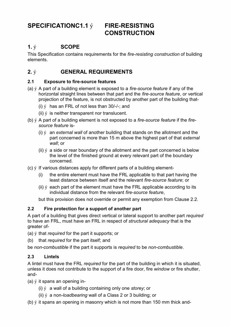
SPECIFICATIONC1.1 ý FIRE-RESISTING CONSTRUCTION
1. ý SCOPE This Specification contains requirements for the fire-resisting construction of building elements.
2. ý GENERAL REQUIREMENTS
2.1 Exposure to fire-source features
(a) ý A part of a building element is exposed to a fire-source feature if any of the horizontal straight lines between that part and the fire-source feature, or vertical projection of the feature, is not obstructed by another part of the building that-
(i) ý has an FRL of not less than 30/-/-; and
(ii) ý is neither transparent nor translucent.
(b) ý A part of a building element is not exposed to a fire-source feature if the fire-source feature is-
(i) ý an external wall of another building that stands on the allotment and the part concerned is more than 15 m above the highest part of that external wall; or
(ii) ý a side or rear boundary of the allotment and the part concerned is below the level of the finished ground at every relevant part of the boundary concerned.
(c) ý If various distances apply for different parts of a building element-
(i) the entire element must have the FRL applicable to that part having the least distance between itself and the relevant fire-source feature; or
(ii) ý each part of the element must have the FRL applicable according to its individual distance from the relevant fire-source feature,
but this provision does not override or permit any exemption from Clause 2.2.
2.2 Fire protection for a support of another part
A part of a building that gives direct vertical or lateral support to another part required to have an FRL, must have an FRL in respect of structural adequacy that is the greater of-
(a) ý that required for the part it supports; or
(b) that required for the part itself; and
be non-combustible if the part it supports is required to be non-combustible.
2.3 Lintels
A lintel must have the FRL required for the part of the building in which it is situated, unless it does not contribute to the support of a fire door, fire window or fire shutter, and-
(a) ý it spans an opening in-
(i) ý a wall of a building containing only one storey; or
(ii) ý a non-loadbearing wall of a Class 2 or 3 building; or
(b) ý it spans an opening in masonry which is not more than 150 mm thick and-

(i) ý not more than 3 m wide if the masonry is non-loadbearing; or
(ii) ý not more than 1.8 m wide if the masonry is loadbearing and part of a solid wall or one of the leaves of a cavity wall.
2.4 Attachments not to impair fire-resistance
(a) ý A combustible material may be used as a finish or lining to a wall or roof, or in a sign, sunscreen or blind, awning, or other attachment to a building element which has the required FRL if-
(i) ý the material is exempted under clause 7 or complies with the Early Fire Hazard Indices prescribed in clause 2 of Specification C1.10;
(ii) ý it is not located near or directly above a required exit so as to make the exit unusable in a fire; and
(iii) ý it does not otherwise constitute an undue risk of fire spread via the facade of the building.
(b) ý The attachment of a facing or finish, or the installation of ducting or any other service, to a part of a building required to have an FRL must not impair the required FRL of that part.
2.5 General concessions
(a) ý Steel columns - Except in a fire wall or common wall, a steel column need not have an FRL in a building that contains only one storey.
(b) ý Structures on roofs - A non-combustible structure situated on a roof need not comply with the other provisions of this Specification if it only contains one or more of the following:
(i) ý Hot water or other water tanks.
(ii) ý Ventilating ductwork, ventilating fans and their motors.
(iii) ý Air-conditioning chillers.
(iv) ý Window cleaning equipment.
(v) ý Lift equipment.
(vi) ý Other service units that are non-combustible and do not contain combustible fluids.
(c) ý Curtain walls and panel walls - A requirement for an external wall to have an FRL does not apply to a curtain wall or panel wall which is of non-combustible construction and fully protected by external automatic drenchers.
3. ý TYPE A FIRE-RESISTING CONSTRUCTION
3.1 Fire-resistance of building elements
In a building required to be of Type A construction-
(a) ý each part mentioned in Table 3, and any beam or column in it, must have an FRL not less than that listed in the Table, for the particular Class of building concerned;
(b) ý external walls, common walls and floors must be non-combustible;
(c) ý any internal wall required to have an FRL must extend to-
(i) ý the underside of the floor next above;
(ii) ý the underside of a roof complying with Table 3; or

(iii) ý a ceiling that is immediately below the roof and has a resistance to the incipient spread of fire to the roof space of not less than 60 minutes;
(d) ý a loadbearing internal wall and a loadbearing fire wall (including those that are part of a loadbearing shaft) must be of concrete or masonry;
(e) ý a non-loadbearing-
(i) ý internal wall required to be fire-resisting; and
(ii) ý lift, ventilating, pipe, garbage, or similar shaft that is not for the discharge of hot products of combustion,
must be of non-combustible construction, and if it is of lightweight construction, must comply with Specification C1.8.
(f) ý any flooring and floor framing in a lift pit must be non-combustible; and
(f) ý the FRLs specified in Table 3 for an external column apply also to those parts of an internal column that face and are within 1.5 m of a window and are exposed through that window to a fire-source feature.
Table 3 TYPE A CONSTRUCTION: FRL OF BUILDING ELEMENTS ý
FRL: (in minutes)
Structural adequacy / Integrity / Insulation
CLASS OF BUILDING
BUILDING ELEMENT 2, 3 or 4 part 5 or 9 6 ý 7 or 8
EXTERNAL WALL or other external building element excluding a roof, where the distance from any fire-source feature to which it is exposed is -
For loadbearing parts-
less than 1.5 m 90/ 90/ 90 120/120/120 180/180/180 240/240/240
1.5 to less than 3 m 90/ 60/ 60 120/ 90/ 90 180/180/120 240/240/180
3 or more 90/ 60/ 30 120/ 60/ 30 180/120/ 90 240/180/ 90
For non-loadbearing parts-
less than 1.5 m 90/ 90/ 90 120/120/120 180/ 180/180 240 /240/240
1.5 to less than 3 m 90/ 60/ 60 120/ 90/ 90 180/ 180/120 240 /240/180
3 m or more - / - / - - / - / - - / - / - - / - / -
EXTERNAL COLUMN not incorporated in an external wall, where the distance from any fire-source feature to which it is exposed is -
less than 3 m 90/ - / - 120/ - / - 180/ - / - 240/ - / -
3 m or more - / - / - - / - / - - / - / - - / - / -
COMMON WALLS and FIRE WALLS - 90/ 90/ 90 120/120/120 180/180/180 240/240/240
INTERNAL WALLS-
Fire-resisting lift and stair shafts-
Loadbearing 90/ 90/ 90 120/120/120 180/120/120 240/120/120
Non-loadbearing 90/ 90/ 90 120/120/120 120/120/120 120/120/120
Bounding public corridors, public hallways and the like-
Loadbearing 90/ 90/ 90 120/ - / - 180/ - / - 240/ - / -
Non-loadbearing 60/ 60/ 60 - / - / - - / - / - - / - / -
Between or bounding sole-occupancy units-
Loadbearing 90/ 90/ 90 120/ -/ - 180/ -/ - 240/ -/ -
Non-loadbearing 60/ 60/ 60 - / - / - - / -/ - - / -/ -
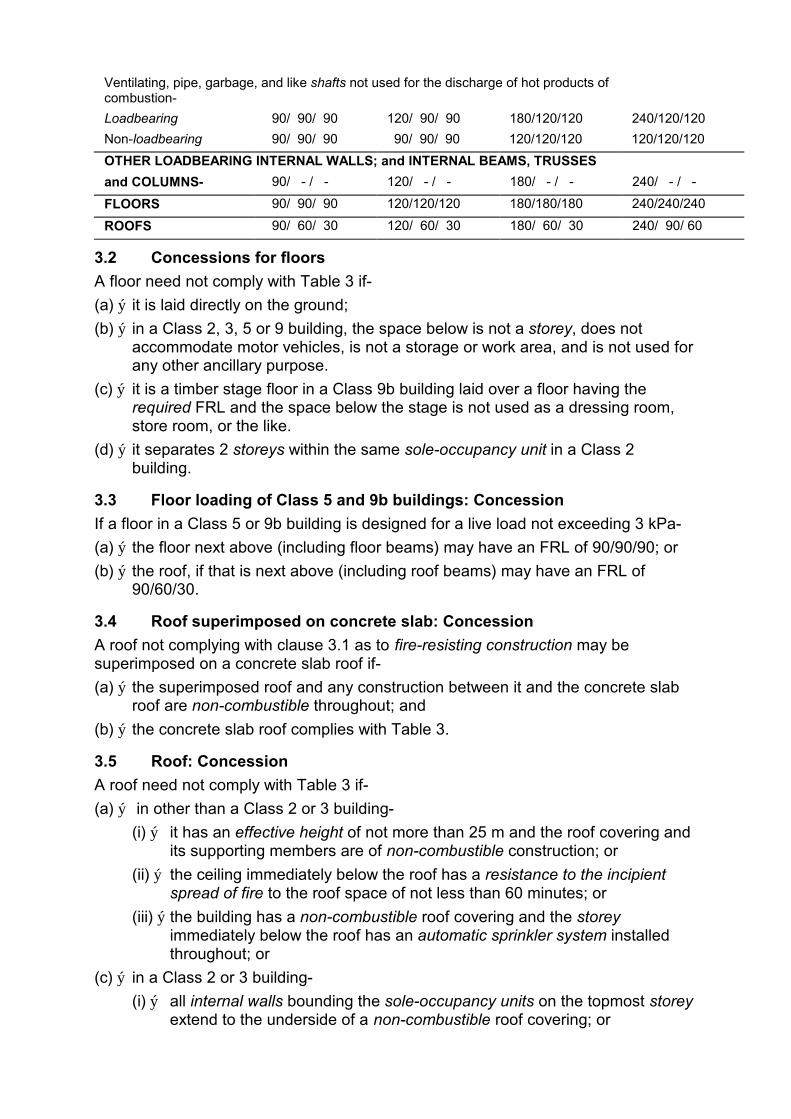
Ventilating, pipe, garbage, and like shafts not used for the discharge of hot products of combustion-
Loadbearing 90/ 90/ 90 120/ 90/ 90 180/120/120 240/120/120
Non-loadbearing 90/ 90/ 90 90/ 90/ 90 120/120/120 120/120/120
OTHER LOADBEARING INTERNAL WALLS; and INTERNAL BEAMS, TRUSSES
and COLUMNS- 90/ - / - 120/ - / - 180/ - / - 240/ - / -
FLOORS 90/ 90/ 90 120/120/120 180/180/180 240/240/240
ROOFS 90/ 60/ 30 120/ 60/ 30 180/ 60/ 30 240/ 90/ 60
3.2 Concessions for floors
A floor need not comply with Table 3 if-
(a) ý it is laid directly on the ground;
(b) ý in a Class 2, 3, 5 or 9 building, the space below is not a storey, does not accommodate motor vehicles, is not a storage or work area, and is not used for any other ancillary purpose.
(c) ý it is a timber stage floor in a Class 9b building laid over a floor having the required FRL and the space below the stage is not used as a dressing room, store room, or the like.
(d) ý it separates 2 storeys within the same sole-occupancy unit in a Class 2 building.
3.3 Floor loading of Class 5 and 9b buildings: Concession
If a floor in a Class 5 or 9b building is designed for a live load not exceeding 3 kPa-
(a) ý the floor next above (including floor beams) may have an FRL of 90/90/90; or
(b) ý the roof, if that is next above (including roof beams) may have an FRL of 90/60/30.
3.4 Roof superimposed on concrete slab: Concession
A roof not complying with clause 3.1 as to fire-resisting construction may be superimposed on a concrete slab roof if-
(a) ý the superimposed roof and any construction between it and the concrete slab roof are non-combustible throughout; and
(b) ý the concrete slab roof complies with Table 3.
3.5 Roof: Concession
A roof need not comply with Table 3 if-
(a) ý in other than a Class 2 or 3 building-
(i) ý it has an effective height of not more than 25 m and the roof covering and its supporting members are of non-combustible construction; or
(ii) ý the ceiling immediately below the roof has a resistance to the incipient spread of fire to the roof space of not less than 60 minutes; or
(iii) ý the building has a non-combustible roof covering and the storey immediately below the roof has an automatic sprinkler system installed throughout; or
(c) ý in a Class 2 or 3 building-
(i) ý all internal walls bounding the sole-occupancy units on the topmost storey extend to the underside of a non-combustible roof covering; or
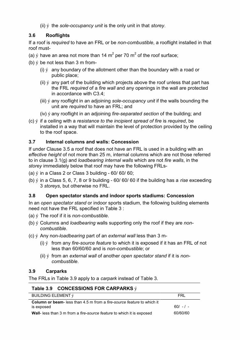
(ii) ý the sole-occupancy unit is the only unit in that storey.
3.6 Rooflights
If a roof is required to have an FRL or be non-combustible, a rooflight installed in that roof must-
(a) ý have an area not more than 14 m2 per 70 m2 of the roof surface;
(b) ý be not less than 3 m from-
(i) ý any boundary of the allotment other than the boundary with a road or public place;
(ii) ý any part of the building which projects above the roof unless that part has the FRL required of a fire wall and any openings in the wall are protected in accordance with C3.4;
(iii) ý any rooflight in an adjoining sole-occupancy unit if the walls bounding the unit are required to have an FRL; and
(iv) ý any rooflight in an adjoining fire-separated section of the building; and
(c) ý if a ceiling with a resistance to the incipient spread of fire is required, be installed in a way that will maintain the level of protection provided by the ceiling to the roof space.
3.7 Internal columns and walls: Concession
If under Clause 3.5 a roof that does not have an FRL is used in a building with an effective height of not more than 25 m, internal columns which are not those referred to in clause 3.1(g) and loadbearing internal walls which are not fire walls, in the storey immediately below that roof may have the following FRLs-
(a) ý in a Class 2 or Class 3 building - 60/ 60/ 60;
(b) ý in a Class 5, 6, 7, 8 or 9 building - 60/ 60/ 60 if the building has a rise exceeding 3 storeys, but otherwise no FRL.
3.8 Open spectator stands and indoor sports stadiums: Concession
In an open spectator stand or indoor sports stadium, the following building elements need not have the FRL specified in Table 3 :
(a) ý The roof if it is non-combustible.
(b) ý Columns and loadbearing walls supporting only the roof if they are non-combustible.
(c) ý Any non-loadbearing part of an external wall less than 3 m-
(i) ý from any fire-source feature to which it is exposed if it has an FRL of not less than 60/60/60 and is non-combustible; or
(ii) ý from an external wall of another open spectator stand if it is non-combustible.
3.9 Carparks
The FRLs in Table 3.9 apply to a carpark instead of Table 3.
Table 3.9 CONCESSIONS FOR CARPARKS ý BUILDING ELEMENT ý FRL
Column or beam- less than 4.5 m from a fire-source feature to which it is exposed 60/ - / -
Wall- less than 3 m from a fire-source feature to which it is exposed 60/60/60

Other steel column- ratio of exposed surface area to mass per unit length not greater than 26 m2/tonne - / - / -
Any other column (other than a column supporting only the roof) 60/ - / -
Fire wall or lift or stair shaft 120/120/120
Any other steel floor beam- which is in continuous contact with a concrete floor slab and has a ratio of exposed surface area to mass per unit length of not more than 30 m2/tonne - / - / -
Any other floor beam 60/ - / -
Floor slab or vehicle ramp 60/ 60/ 60
Roof and columns supporting only the roof - / - / -
3.10 Mezzanine floors: Concession
Except in a Class 9b building which is a spectator viewing area that accommodates more than 100 persons under D1.13, mezzanine floors and any supporting building elements need not have an FRL or be non-combustible if every wall or column that supports any part of the building other than the mezzanine floor or floors within 6 m of a mezzanine floor has its FRL increased from that otherwise required as set out Table 3.10.
Table 3.10 INCREASED FRLs - CONSTRUCTION SURROUNDING MEZZANINES
LEVEL OTHERWISE REQUIRED FOR ANY INCREASE IN LEVEL TO (not less than): FRL CRITERION (mins)
30 60
60 90
90 120
120 180
180 240
240 240
The increase in level applies to each FRL criterion (structural adequacy, integrity or insulation) relevant to the building element concerned.
4. ý TYPE B FIRE-RESISTING CONSTRUCTION
4.1 Fire-resistance of building elements
In a building required to be of Type B construction-
(a) ý each part mentioned in Table 4, and any beam or column in it, must have an FRL not less than that listed in the Table for the particular Class of building concerned;
(b) ý a common wall, the flooring and floor framing in any lift pit, and an external wall where an FRL is listed in Table 4, must be non-combustible;
(c) ý if a stair shaft supports any floor or a structural part of it-
(i) ý the floor or part must have an FRL of 60/-/- or more; or
(ii) ý the junction of the stair shaft must be constructed so that the floor or part will be free to sag or fall in a fire without causing structural damage to the shaft;
(d) ý any internal wall which is required to have an FRL must extend to-
(i) ý the underside of the floor next above if that floor has an FRL of at least 30/30/30; or
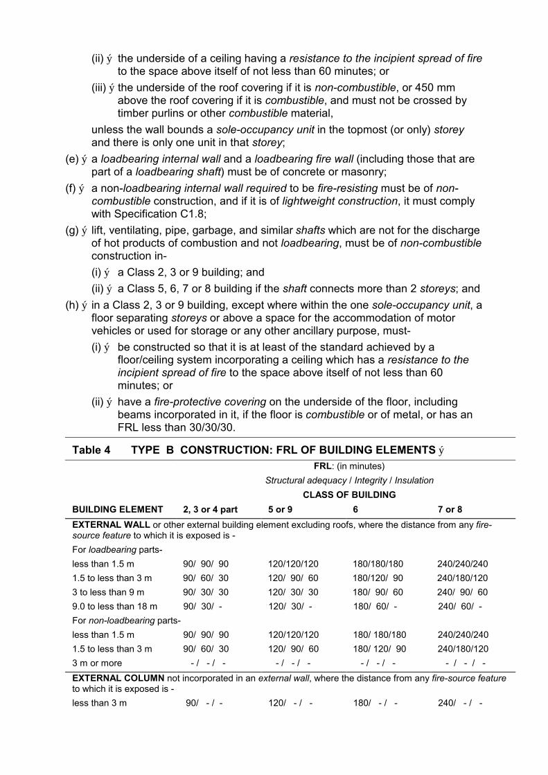
(ii) ý the underside of a ceiling having a resistance to the incipient spread of fire to the space above itself of not less than 60 minutes; or
(iii) ý the underside of the roof covering if it is non-combustible, or 450 mm above the roof covering if it is combustible, and must not be crossed by timber purlins or other combustible material,
unless the wall bounds a sole-occupancy unit in the topmost (or only) storey and there is only one unit in that storey;
(e) ý a loadbearing internal wall and a loadbearing fire wall (including those that are part of a loadbearing shaft) must be of concrete or masonry;
(f) ý a non-loadbearing internal wall required to be fire-resisting must be of non-combustible construction, and if it is of lightweight construction, it must comply with Specification C1.8;
(g) ý lift, ventilating, pipe, garbage, and similar shafts which are not for the discharge of hot products of combustion and not loadbearing, must be of non-combustible construction in-
(i) ý a Class 2, 3 or 9 building; and
(ii) ý a Class 5, 6, 7 or 8 building if the shaft connects more than 2 storeys; and
(h) ý in a Class 2, 3 or 9 building, except where within the one sole-occupancy unit, a floor separating storeys or above a space for the accommodation of motor vehicles or used for storage or any other ancillary purpose, must-
(i) ý be constructed so that it is at least of the standard achieved by a floor/ceiling system incorporating a ceiling which has a resistance to the incipient spread of fire to the space above itself of not less than 60 minutes; or
(ii) ý have a fire-protective covering on the underside of the floor, including beams incorporated in it, if the floor is combustible or of metal, or has an FRL less than 30/30/30.
Table 4 TYPE B CONSTRUCTION: FRL OF BUILDING ELEMENTS ý FRL: (in minutes)
Structural adequacy / Integrity / Insulation
CLASS OF BUILDING
BUILDING ELEMENT 2, 3 or 4 part 5 or 9 6 7 or 8
EXTERNAL WALL or other external building element excluding roofs, where the distance from any fire-source feature to which it is exposed is -
For loadbearing parts-
less than 1.5 m 90/ 90/ 90 120/120/120 180/180/180 240/240/240
1.5 to less than 3 m 90/ 60/ 30 120/ 90/ 60 180/120/ 90 240/180/120
3 to less than 9 m 90/ 30/ 30 120/ 30/ 30 180/ 90/ 60 240/ 90/ 60
9.0 to less than 18 m 90/ 30/ - 120/ 30/ - 180/ 60/ - 240/ 60/ -
For non-loadbearing parts-
less than 1.5 m 90/ 90/ 90 120/120/120 180/ 180/180 240/240/240
1.5 to less than 3 m 90/ 60/ 30 120/ 90/ 60 180/ 120/ 90 240/180/120
3 m or more - / - / - - / - / - - / - / - - / - / -
EXTERNAL COLUMN not incorporated in an external wall, where the distance from any fire-source feature to which it is exposed is -
less than 3 m 90/ - / - 120/ - / - 180/ - / - 240/ - / -
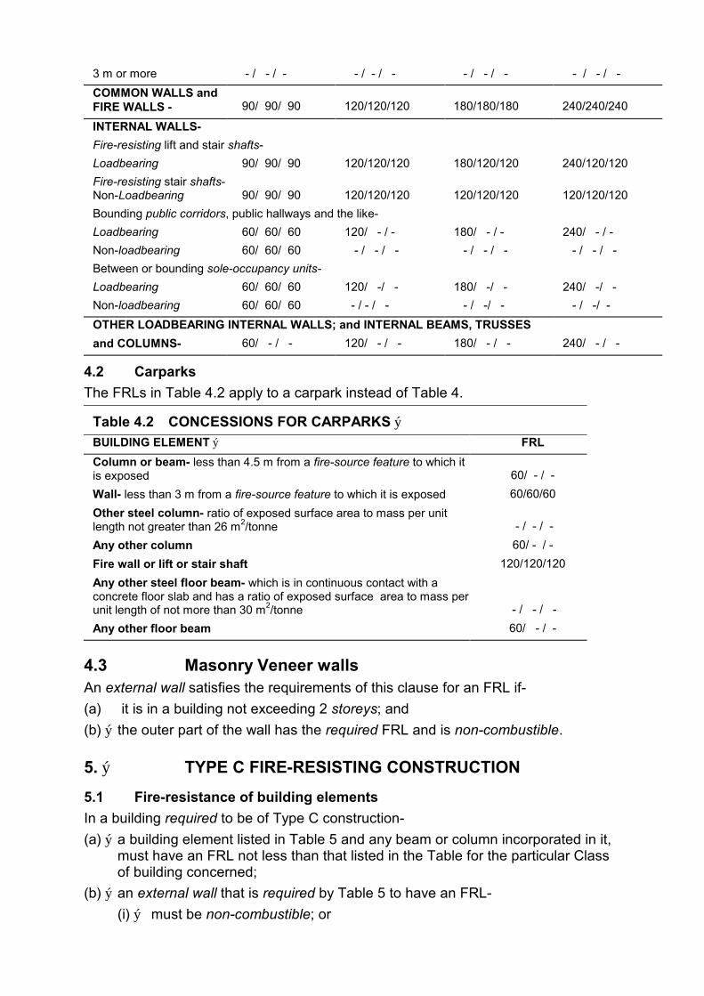
3 m or more - / - / - - / - / - - / - / - - / - / -
COMMON WALLS and FIRE WALLS - 90/ 90/ 90 120/120/120 180/180/180 240/240/240
INTERNAL WALLS-
Fire-resisting lift and stair shafts-
Loadbearing 90/ 90/ 90 120/120/120 180/120/120 240/120/120
Fire-resisting stair shafts-Non-Loadbearing 90/ 90/ 90 120/120/120 120/120/120 120/120/120
Bounding public corridors, public hallways and the like-
Loadbearing 60/ 60/ 60 120/ - / - 180/ - / - 240/ - / -
Non-loadbearing 60/ 60/ 60 - / - / - - / - / - - / - / -
Between or bounding sole-occupancy units-
Loadbearing 60/ 60/ 60 120/ -/ - 180/ -/ - 240/ -/ -
Non-loadbearing 60/ 60/ 60 - / - / - - / -/ - - / -/ -
OTHER LOADBEARING INTERNAL WALLS; and INTERNAL BEAMS, TRUSSES
and COLUMNS- 60/ - / - 120/ - / - 180/ - / - 240/ - / -
4.2 Carparks
The FRLs in Table 4.2 apply to a carpark instead of Table 4.
Table 4.2 CONCESSIONS FOR CARPARKS ý BUILDING ELEMENT ý FRL
Column or beam- less than 4.5 m from a fire-source feature to which it is exposed 60/ - / -
Wall- less than 3 m from a fire-source feature to which it is exposed 60/60/60
Other steel column- ratio of exposed surface area to mass per unit length not greater than 26 m2/tonne - / - / -
Any other column 60/ - / -
Fire wall or lift or stair shaft 120/120/120
Any other steel floor beam- which is in continuous contact with a concrete floor slab and has a ratio of exposed surface area to mass per unit length of not more than 30 m2/tonne - / - / -
Any other floor beam 60/ - / -
4.3 Masonry Veneer walls An external wall satisfies the requirements of this clause for an FRL if-
(a) it is in a building not exceeding 2 storeys; and
(b) ý the outer part of the wall has the required FRL and is non-combustible.
5. ý TYPE C FIRE-RESISTING CONSTRUCTION
5.1 Fire-resistance of building elements
In a building required to be of Type C construction-
(a) ý a building element listed in Table 5 and any beam or column incorporated in it, must have an FRL not less than that listed in the Table for the particular Class of building concerned;
(b) ý an external wall that is required by Table 5 to have an FRL-
(i) ý must be non-combustible; or

(ii) ý the outer part of the wall must have the required FRL and be non-combustible;
(c) ý in a building with a rise of 2 storeys, a fire wall-
(i) ý if loadbearing - must be of concrete or masonry; or
(ii) ý if non-loadbearing - must be of non-combustible construction and if it is of lightweight construction, it must comply with Specification C1.8;
(d) ý in a Class 2 or 3 building, an internal wall bounding a sole-occupancy unit or separating adjoining units-
(i) ý if loadbearing - must be of concrete or masonry; or
(ii) ý if non-loadbearing - must be of non-combustible construction and comply with Specification C1.8;
(e) ý in a Class 2 or 3 building an internal wall which is required by Table 5 to have an FRL must extend-
(i) ý to the underside of the floor next above if that floor has an FRL of at least 30/30/30 or a fire-protective covering on the underside of the floor; or
(ii) ý to the underside of a ceiling having a resistance to the incipient spread of fire to the space above itself of not less than 60 minutes; or
(iii) ý to the underside of the roof covering if it is non-combustible, or 450 mm above the adjoining roof covering if it is combustible, and must not be crossed by timber purlins or other combustible material,
unless the wall bounds a sole-occupancy unit in the topmost (or only) storey and there is only one unit in that storey;
(f) ý except where within the one sole-occupancy unit, a floor separating storeys in a Class 2, 3 or 9 building, or above a space for the accommodation of motor vehicles or used for storage or any other ancillary purpose, and any column supporting the floor, must-
(i) ý have an FRL of at least 30/ 30/ 30; or
(ii) ý have a fire-protective covering on the underside of the floor including beams incorporated in it and around the column, if the floor or column is combustible or of metal.
Table 5 TYPE C CONSTRUCTION: FRL OF BUILDING ELEMENTS ý FRL: (in minutes)
Structural adequacy / Integrity / Insulation
CLASS OF BUILDING
BUILDING ELEMENT 2, 3 or 4 part 5 or 9 6 7 or 8
EXTERNAL WALL or other external building element excluding a roof, where the distance from any fire-source feature to which it is exposed is -
less than 1.5 m 90/ 90/ 90 90/ 90/ 90 90/ 90/ 90 90/ 90/ 90
EXTERNAL COLUMN not incorporated in an external wall, where the distance from any fire-source feature to which it is exposed is -
less than 1.5 m 90/ - / - 90/ - / - 90/ - / - 90/ - / -
COMMON WALLS and FIRE WALLS - 90/ 90/ 90 90/ 90/ 90 90/ 90/ 90 90/ 90/ 90
INTERNAL WALLS-
Bounding public corridors, public hallways
and the like- 60 / 60/ 60 - / - / - - / - / - - / - / -

Between or bounding
sole-occupancy units- 60/ 60/ 60 - / - / - - / -/ - - / -/ -
Bounding a stair if required to be rated- 60/ 60/ 60 - / - / - - / -/ - - / -/ -
5.2 Carparks
The FRLs in Table 5.3 apply to a carpark instead of Table 5.
Table 5.3 CONCESSIONS FOR CARPARKS BUILDING ELEMENT FRL
Column or beam- less than 1.5 m from a fire-source feature to which it 60/ - / -is exposed
Wall- less than 1.5 m from a fire-source feature to which it is exposed 60/60/60
Other steel column- ratio of exposed surface area to mass per unit length not greater than 26 m2/tonne - / - / -
Any other column 60/ - / -
Any other steel floor beam- which is in continuous contact with a concrete floor slab and has a ratio of exposed surface area to mass per unit length of not more than 30 m2/tonne - / - / -
Any other floor beam 60/ - / -
SPECIFICATION C1.8 ý STRUCTURAL TESTS FOR LIGHTWEIGHT CONSTRUCTION
1. ý Scope This Specification contains details of the tests to be applied and criteria to be satisfied by lightweight construction.
2. ý Definition Lightweight construction is-
(a) ý fire-resisting construction which-
(i) ý is not in continuous contact with the principal construction that it protects from fire; or
(ii) ý is of sheet or board material, plaster, render, sprayed application, or other material similarly susceptible to damage by pressure or abrasion;
(b) ý fire-resisting construction which incorporates or comprises-
(i) ý concrete containing pumice, perlite, vermiculite, or other soft material; or
(ii) ý masonry having a thickness less than 70 mm.
3. ý Application The tests prescribed in this specification apply to construction other than concrete or masonry, which need not be tested in accordance with this specification if it is designed-
(a) ý in accordance with this Code; and
(b) ý to resist, as serviceability loads, the appropriate pressure and impact defined in this Specification, to the extent that such resistance is not provided through compliance with (a).

4. ý Test methods Tests must be carried out in accordance with the following:
(a) ý Materials tests - in accordance with the methods specified for the constituent materials of the construction in the standards adopted by reference in this Code.
(b) ý For resistance to static pressure - The provisions for testing walls under transverse load in ASTM E72-80, except that the chamber method must not be used.
(c) ý For resistance to impact - The provisions for testing wall systems in ASTM E695-79 (1985), except that-
(i) the points of impact must be set at 1.5 m above finished floor level or 1.5 m above the part of the specimen that corresponds to finished floor level;
(ii) ý the impact bag must be not less than 225 mm in diameter and not more than 260 mm in diameter and weigh 27.2 + 0.1 kg;
(iii) ý the mass must be achieved by putting loose, dry sand into the bag and must be adjusted before each series of impact tests; and
(iv) ý the method may be used also for walls that depart from the vertical or that are curved and in cases where the pendulum bag and suspension cannot be vertical at the instant of impact on a concave surface or a surface inclined towards the impact, the height of drop is the net height at the point of impact.
(d) ý For resistance to surface indentation - for all materials irrespective of composition: AS 2185.
(e) ý For resistance of lift shaft construction to repetitive load - as for 3(b)except that-
(i) ý the load must be applied dynamically at a frequency not less than 1 Hz and not more than 3 Hz; and
(ii) ý it is sufficient to test one specimen with the pressure applied from the side of the construction on which the lift will operate.
5. ý Test specimens Tests must be carried out on construction insitu or on specimens of the construction in accordance with clause 4 except that-
(a) ý test specimens of the construction must be supported at top and bottom (or at each end if tested horizontally) by components identical with, and in a manner identical with, the actual construction; and
(b) ý the heights of the test specimens (or lengths, if the specimens are tested horizontally) must be identical with the height between those supports in the actual construction.
6. ý Criteria of compliance The following criteria must be adopted to determine compliance with this Specification:
(a) ý Material - Material must comply with the applicable standard adopted by reference in this Code.
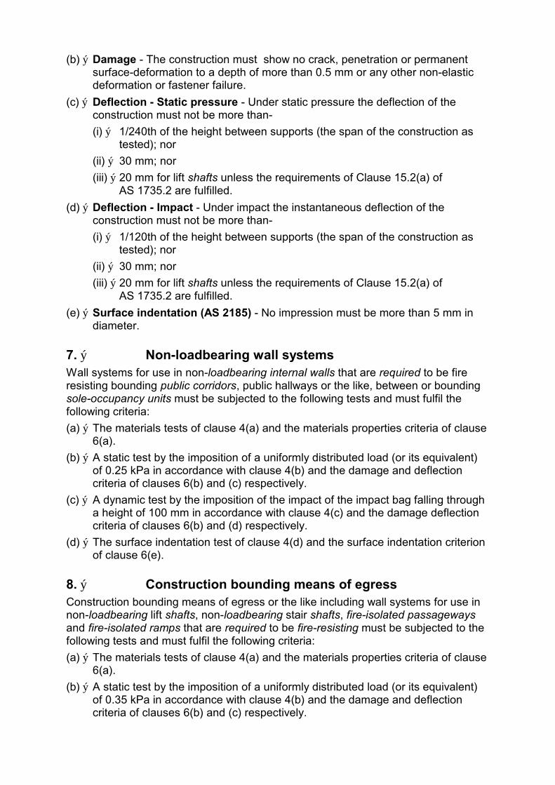
(b) ý Damage - The construction must show no crack, penetration or permanent surface-deformation to a depth of more than 0.5 mm or any other non-elastic deformation or fastener failure.
(c) ý Deflection - Static pressure - Under static pressure the deflection of the construction must not be more than-
(i) ý 1/240th of the height between supports (the span of the construction as tested); nor
(ii) ý 30 mm; nor
(iii) ý 20 mm for lift shafts unless the requirements of Clause 15.2(a) of AS 1735.2 are fulfilled.
(d) ý Deflection - Impact - Under impact the instantaneous deflection of the construction must not be more than-
(i) ý 1/120th of the height between supports (the span of the construction as tested); nor
(ii) ý 30 mm; nor
(iii) ý 20 mm for lift shafts unless the requirements of Clause 15.2(a) of AS 1735.2 are fulfilled.
(e) ý Surface indentation (AS 2185) - No impression must be more than 5 mm in diameter.
7. ý Non-loadbearing wall systems Wall systems for use in non-loadbearing internal walls that are required to be fire resisting bounding public corridors, public hallways or the like, between or bounding sole-occupancy units must be subjected to the following tests and must fulfil the following criteria:
(a) ý The materials tests of clause 4(a) and the materials properties criteria of clause 6(a).
(b) ý A static test by the imposition of a uniformly distributed load (or its equivalent) of 0.25 kPa in accordance with clause 4(b) and the damage and deflection criteria of clauses 6(b) and (c) respectively.
(c) ý A dynamic test by the imposition of the impact of the impact bag falling through a height of 100 mm in accordance with clause 4(c) and the damage deflection criteria of clauses 6(b) and (d) respectively.
(d) ý The surface indentation test of clause 4(d) and the surface indentation criterion of clause 6(e).
8. ý Construction bounding means of egress Construction bounding means of egress or the like including wall systems for use in non-loadbearing lift shafts, non-loadbearing stair shafts, fire-isolated passageways and fire-isolated ramps that are required to be fire-resisting must be subjected to the following tests and must fulfil the following criteria:
(a) ý The materials tests of clause 4(a) and the materials properties criteria of clause 6(a).
(b) ý A static test by the imposition of a uniformly distributed load (or its equivalent) of 0.35 kPa in accordance with clause 4(b) and the damage and deflection criteria of clauses 6(b) and (c) respectively.

(c) ý A dynamic test by the imposition of the impact of the impact bag falling through a height of 150 mm in accordance with clause 3(c) and the damage and deflection criteria of clauses 6(b) and (d) respectively.
(d) ý The surface indentation test of clause 4(d) and the surface indentation criterion of clause 6(e).
9. ý Requirements for certain Class 9b buildings Wall systems for use in spectator stands, sports stadia, cinemas or theatres, railway or omnibus stations, or airport terminals, in non-loadbearing-
(a) ý lift shafts or stair shafts;
(b) ý external and internal walls bounding public corridors, public hallways or the like, including fire-isolated and non-fire-isolated passageways or ramps,
must be subjected to the following tests and must fulfil the following criteria:
(i) ý The materials tests of clause 4(a) and the materials properties criteria of clause 6(a).
(ii) ý A static test by the imposition of a uniformly distributed load (or its equivalent) of 1.0 kPa in accordance with clause 4(b) and the damage and deflection criteria of clauses 6(b) and (c) respectively.
(iii) ý A dynamic test by the imposition of the impact of the impact bag falling through a height of 350 mm in accordance with clause 4(c) and the damage and deflection criteria of clauses 6(b) and (d) respectively.
(iv) ý The surface indentation test of clause 4(d) and the surface indentation criterion of clause 6(e).
10. Lift shafts In addition to the requirements of clauses 8 and 9, wall systems for use in non-loadbearing lift shafts that are required to be fire-resisting must be subjected to dynamic test by the imposition of 106 cycles of a uniformly distributed load (or its equivalent) between 0 and 0.35 kPa in accordance with clause 4(e) and must fulfil the damage criteria of clause 6(b).
SPECIFICATION C1.9 ý FIRE-RESISTANCE OF CLASS 1 AND 10 BUILDINGS
1. ý Scope This Specification sets out the requirements for the construction of Class 1 and 10a buildings to resist the spread of fire.
2. ý External walls of Class 1 buildings Except as permitted by Clause 5 or 6, an external wall of a Class 1 building and any openings in that wall, must comply with Clause 3 if-
(a) ý the wall is set back less than 1 m from an allotment boundary other than the boundary adjoining a road alignment or other public space; or
(b) ý the wall is less than 2 m from another building on the same allotment other than a Class 10 building .
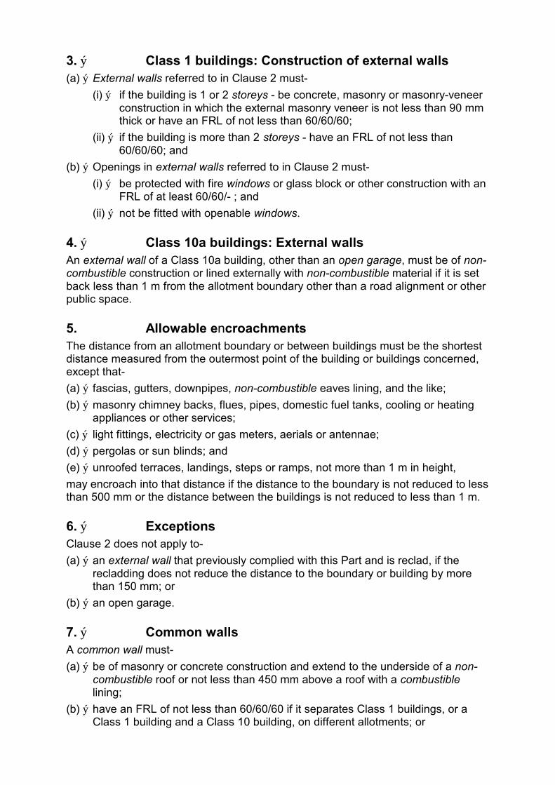
3. ý Class 1 buildings: Construction of external walls (a) ý External walls referred to in Clause 2 must-
(i) ý if the building is 1 or 2 storeys - be concrete, masonry or masonry-veneer construction in which the external masonry veneer is not less than 90 mm thick or have an FRL of not less than 60/60/60;
(ii) ý if the building is more than 2 storeys - have an FRL of not less than 60/60/60; and
(b) ý Openings in external walls referred to in Clause 2 must-
(i) ý be protected with fire windows or glass block or other construction with an FRL of at least 60/60/- ; and
(ii) ý not be fitted with openable windows.
4. ý Class 10a buildings: External walls An external wall of a Class 10a building, other than an open garage, must be of non-combustible construction or lined externally with non-combustible material if it is set back less than 1 m from the allotment boundary other than a road alignment or other public space.
5. Allowable encroachments The distance from an allotment boundary or between buildings must be the shortest distance measured from the outermost point of the building or buildings concerned, except that-
(a) ý fascias, gutters, downpipes, non-combustible eaves lining, and the like;
(b) ý masonry chimney backs, flues, pipes, domestic fuel tanks, cooling or heating appliances or other services;
(c) ý light fittings, electricity or gas meters, aerials or antennae;
(d) ý pergolas or sun blinds; and
(e) ý unroofed terraces, landings, steps or ramps, not more than 1 m in height,
may encroach into that distance if the distance to the boundary is not reduced to less than 500 mm or the distance between the buildings is not reduced to less than 1 m.
6. ý Exceptions Clause 2 does not apply to-
(a) ý an external wall that previously complied with this Part and is reclad, if the recladding does not reduce the distance to the boundary or building by more than 150 mm; or
(b) ý an open garage.
7. ý Common walls A common wall must-
(a) ý be of masonry or concrete construction and extend to the underside of a non-combustible roof or not less than 450 mm above a roof with a combustible lining;
(b) ý have an FRL of not less than 60/60/60 if it separates Class 1 buildings, or a Class 1 building and a Class 10 building, on different allotments; or
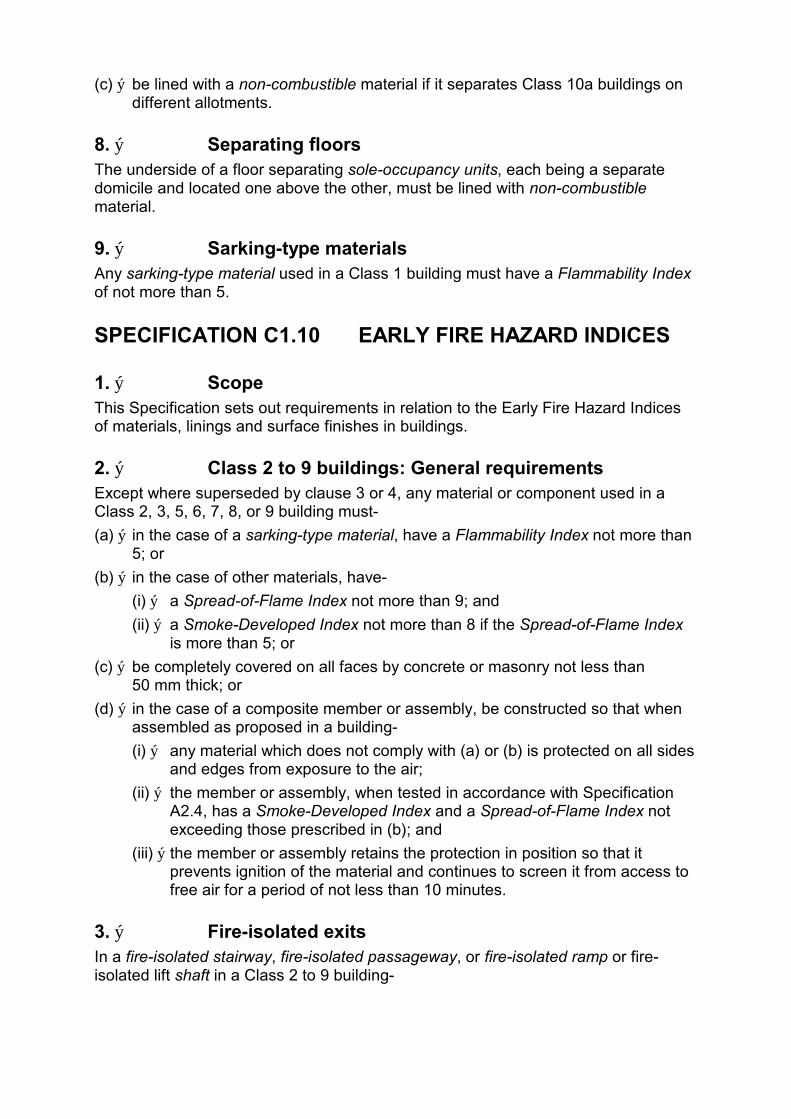
(c) ý be lined with a non-combustible material if it separates Class 10a buildings on different allotments.
8. ý Separating floors The underside of a floor separating sole-occupancy units, each being a separate domicile and located one above the other, must be lined with non-combustible material.
9. ý Sarking-type materials Any sarking-type material used in a Class 1 building must have a Flammability Index of not more than 5.
SPECIFICATION C1.10 EARLY FIRE HAZARD INDICES
1. ý Scope This Specification sets out requirements in relation to the Early Fire Hazard Indices of materials, linings and surface finishes in buildings.
2. ý Class 2 to 9 buildings: General requirements Except where superseded by clause 3 or 4, any material or component used in a Class 2, 3, 5, 6, 7, 8, or 9 building must-
(a) ý in the case of a sarking-type material, have a Flammability Index not more than 5; or
(b) ý in the case of other materials, have-
(i) ý a Spread-of-Flame Index not more than 9; and
(ii) ý a Smoke-Developed Index not more than 8 if the Spread-of-Flame Index is more than 5; or
(c) ý be completely covered on all faces by concrete or masonry not less than 50 mm thick; or
(d) ý in the case of a composite member or assembly, be constructed so that when assembled as proposed in a building-
(i) ý any material which does not comply with (a) or (b) is protected on all sides and edges from exposure to the air;
(ii) ý the member or assembly, when tested in accordance with Specification A2.4, has a Smoke-Developed Index and a Spread-of-Flame Index not exceeding those prescribed in (b); and
(iii) ý the member or assembly retains the protection in position so that it prevents ignition of the material and continues to screen it from access to free air for a period of not less than 10 minutes.
3. ý Fire-isolated exits In a fire-isolated stairway, fire-isolated passageway, or fire-isolated ramp or fire-isolated lift shaft in a Class 2 to 9 building-

(a) ý a material, other than a sarking-type material, used in a ceiling, used as an attachment to a structural member or as a finish, surface or lining to a structural member, must-
(i) ý have a Spread-of-Flame Index of 0;
(ii) ý have a Smoke-Developed Index of not more than 2; and
(iii) ý if combustible, be attached directly to a non-combustible substrate and not exceed 1 mm in finished thickness;
(b) ý a sarking-type material used in the form of an exposed wall or ceiling, or as a finish or attachment thereto, must have a Flammability Index of 0.
4. ý Class 2, 3 and 9 buildings: Public areas A material, other than a sarking-type material must have a Spread-of-Flame Index of 0 and a Smoke-Developed Index not more than 5 if it is used-
(a) ý in a Class 2, 3, 9a or 9b building - as a finish, surface, lining or attachment to any wall or ceiling in an internal public corridor, hallway, or the like, which is a means of egress to-
(i) ý a stairway required to be fire-isolated or an external stairway used instead; or
(ii) ý a passageway, or ramp, required to be fire-isolated; or
(b) ý in a Class 9b building used as a theatre, public hall, or the like-
(i) ý as a finish, surface, lining, or attachment to any ceiling, wall or floor;
(ii) ý as the covering of fixed seating in the audience seating area; or
(iii) ý in a cinema projection room.
5. ý Materials deemed to comply A material complies with clauses 2, 3 or 4 if it is-
(a) ý plaster, cement render, concrete, terrazzo, ceramic tile or the like; or
(b) ý a fire-protective covering.
6. ý Fire-retardant coatings not acceptable Paint or fire-retardant coatings must not be used in order to make a substrate comply with a required Spread-of-Flame Index, Smoke-Developed Index or Flammability Index.
7. ý Exempted building parts and materials The requirements in this Specification for a Spread-of-Flame Index, Smoke-Developed Index or Flammability Index do not apply to-
(a) ý timber-framed windows;
(b) ý solid timber handrails or skirtings;
(c) ý timber-faced solid-core or fire doors;
(d) ý electrical switches, outlets, cover plates or the like;
(e) ý materials used for-
(i) ý roof covering or membranes, or roof insulating material, applied in continuous contact with a substrate;
(ii) ý adhesives; or
(iii) ý damp-proof courses, flashing, caulking, sealing, ground moisture barriers, or the like;
(f) ý paint, varnish, lacquer or similar finish, other than nitro-cellulose lacquer;
(g) ý a clear or translucent rooflight of glass fibre reinforced polyester if-
(i) ý the roof in which it is installed forms part of a single storey building required to be of Type C construction;
(ii) ý the material is used as part of the roof covering;
(iii) ý it is not prohibited by any other clause of the BCA;
(iv) ý it is not closer than 1.5 m from another rooflight of the same type;
(v) ý each rooflight is not more than 14 m2 in area; and
(vi) ý the area of the rooflights per 70 m2 of roof surface is not more than 14 m2; or
(h) ý any other material that does not significantly increase the hazards of fire.
SPECIFICATION C3.4 ý FIRE DOORS, SMOKE DOORS, FIRE WINDOWS AND SHUTTERS
1. ý Scope This Specification sets out requirements for the construction of fire doors, smoke doors, fire windows and fire shutters.
2. ý Fire doors A required fire door must comply with AS 1905.1, except that-
(a) ý it may be fully glazed or incorporate glazing if the tested prototype was similarly glazed;
(b) ý the radiation level at a distance of 365 mm from the face of the glazing must not exceed 10 kW/m2 during the period corresponding to that for integrity in the required FRL;
(c) ý the rise in average temperature on the side of the tested prototype remote from the furnace must not exceed 140 K (except in any glazed part) during the first 30 minutes of the fire test.
3. ý Smoke doors A required smoke door must-
(a) ý be side-hung and may have one or 2 door leaves;
(b) ý swing-
(i) ý in the direction of egress; or
(ii) ý in both directions if the path of travel to exits is in either direction;
(c) ý be self-closing and may be fitted with an automatic release device; and
(d) ý be constructed of-
(i) ý solid-core at least 35 mm thick, glazed panels in a timber frame at least 35 mm thick, or a metal frame, with a mid-rail or suitable crash bar; or

(ii) PVC, or other suitable material, ý
and if necessary, fitted with smoke seals. ý
4. ý Fire shutters A required fire shutter must-
(a) ý be a shutter that-
(i) ý is identical with a tested prototype that has achieved the required FRL; and
(ii) ý is installed in the same manner and in an opening that is not larger than the tested prototype; and
(iii) ý did not have a rise in average temperature on the side remote from the furnace of more than 140 K during the first 30 minutes of the test; or
(b) ý is a steel shutter complying with AS 1905.2 if a metallic fire shutter is not prohibited by C3.5.
5. Fire windows A required fire window must be-
(a) ý identical in construction with a prototype that has achieved the required FRL; and
(b) ý installed in the same manner and in an opening that is not larger than the tested prototype.
SPECIFICATION C3.15 ý PENETRATION OF WALLS, FLOORS AND CEILINGS BY SERVICES
1. ý Scope This Specification prescribes materials and methods of installation for services that penetrate walls, floors and ceilings required to have an FRL.
2. ý Application (a) ý This Specification applies to installations permitted under this Code as
alternatives to systems that have been demonstrated by test to fulfil the requirements of C3.14.
(b) ý This Specification does not apply to installations in ceilings required to have a resistance to the incipient spread of fire nor to the installation of piping that contains or is intended to contain a flammable liquid or gas.
3. ý Metal pipes (a) ý A metal pipe that is not normally filled with liquid must not penetrate a wall, floor
or ceiling within 100 mm of any combustible material, and must be constructed of-
(i) copper alloy or stainless steel with a wall thickness of at least 1 mm; or

(ii) ý cast iron or steel (other than stainless steel) with a wall thickness of at least 2 mm.
(b) ý An opening for a metal pipe must-
(i) ý be neatly formed, cut or drilled;
(ii) ý be no closer than 200 mm to any other service penetration; and
(iii) ý accommodate only one pipe.
(c) ý A metal pipe must be wrapped but must not be lagged or enclosed in thermal insulation over the length of its penetration of a wall, floor or ceiling unless the lagging or thermal insulation fulfils the requirements of clause 7.
(d) ý The gap between a metal pipe and the wall, floor or ceiling it penetrates must be fire-stopped in accordance with clause 7.
4. ý Pipes penetrating sanitary compartments If a pipe of metal or UPVC penetrates the floor of a sanitary compartment in accordance with C3.15(e) of this Code-
(a) ý the opening must be neatly formed and no larger than is necessary to accommodate the pipe or fitting; and
(b) ý the gap between pipe and floor must be fire-stopped in accordance with clause 7.
5. ý Wires and cables If a wire or cable or cluster of wires or cables penetrates a floor, wall or ceiling-
(a) ý the opening must be neatly formed, cut or drilled and no closer than 50 mm to any other service opening; and
(b) ý the opening must be no larger in cross-sectional area than-
(i) ý 2000 mm2 if only a single cable is accommodated and the gap between cable and wall, floor or ceiling is no wider than 15 mm; or
(ii) ý 500 mm2 in any other case; and
(c) ý the gap between the service and the wall, floor or ceiling must be fire-stopped in accordance with clause 7.
6. ý Electrical switches and outlets If an electrical switch, outlet, socket or the like is accommodated in an opening or recess in a wall, floor or ceiling-
(a) ý the opening or recess must not-
(i) ý be located opposite any point within 300 mm horizontally or 600 mm vertically of any opening or recess on the opposite side of the wall; or
(ii) ý extend beyond half the thickness of the wall; and
(b) ý the gap between the service and the wall, floor or ceiling must be fire-stopped in accordance with clause 7.
7. ý Fire-stopping (a) ý Material: The material used for the fire-stopping of service penetrations must
be concrete, high-temperature mineral fibre, high-temperature ceramic fibre or

other material that does not flow at a temperature below 1120oC when tested in accordance with AS 1038.15, and must have-
(i) ý demonstrated in a system tested in accordance with C3.15(a) of this Code that it does not impair the fire-resisting performance of the building element in which it is installed; or
(ii) ý demonstrated in a test in accordance with (e) that it does not impair the fire-resisting performance of the test slab.
(b) ý Installation: Fire-stopping material must be packed into the gap between the service and wall, floor or ceiling in a manner, and compressed to the same degree, as adopted for testing under 8(a)(i) or (ii).
(c) ý Hollow construction: If a pipe penetrates a hollow wall (such as a stud wall, a cavity wall or a wall of hollow blockwork) or a hollow floor/ceiling system, the cavity must be so framed and packed with fire-stopping material that the material is-
(i) ý installed in accordance with 7(b) to a thickness of 25 mm all round the service for the full length of the penetration; and
(ii) ý restrained, independently of the service, from moving or parting from the surfaces of the service and of the wall, floor or ceiling.
(d) ý Recesses: If an electrical switch, socket, outlet or the like is accommodated in a recess in a hollow wall or hollow floor/ceiling system-
(i) ý the cavity immediately behind the service must be framed and packed with fire-stopping material in accordance with 7(c); or
(ii) ý the back and sides of the service must be protected with refractory lining board identical with and to the same thickness as that in which the service is installed.
(e) ý Test: The test to demonstrate compliance of a fire-stopping material with this Specification must be conducted as follows:
(i) ý The test specimen must comprise a concrete slab not less than 1 m square and not more than 100 mm thick, and appropriately reinforced if necessary for structural adequacy during manufacture, transport and testing.
(ii) ý The slab must have a hole 50 mm in diameter through the centre and the hole must be packed with the fire-stopping material.
(iii) ý The slab must be conditioned in accordance with AS 1530.4.
(iv) ý Two thermocouples complying with AS 1530.4 must be attached to the upper surface of the packing each about 5 mm from its centre.
(v) ý The slab must be tested on flat generally in accordance with Section 10 of AS 1530.4 and must achieve an FRL of 60/60/60 or as otherwise required.
************************************************************************************************
SECTION D ACCESS AND EGRESS
CONTENTS
D1 Provision for Escape D1.1 Application
D1.2 Number of exits required
D1.3 When fire-isolated exits are required
D1.4 Exit travel distances
D1.5 Distance between alternative exits
D1.6 Dimensions of exits
D1.7 Travel via fire-isolated exits
D1.8 External stairways
D1.9 Travel by non-fire-isolated stairways or ramps
D1.10 Discharge from exits
D1.11 Horizontal exits
D1.12 Non-required stairways, ramps or escalators
D1.13 Number of persons accommodated
D1.14 Measurement of distances
D1.15 Method of measurement
D2 Construction of Exits D2.1 Application of Part
D2.2 Fire-isolated stairways and ramps
D2.3 Non-fire-isolated stairways and ramps
D2.4 Separation of rising and descending stair flights
D2.5 Open access ramps and balconies
D2.6 Smoke lobbies
D2.7 Installations in exits and paths of travel
D2.8 Enclosure of space under stairs and ramps
D2.9 Width of stairways
D2.10 Pedestrian ramps
D2.11 Fire-isolated passageways
D2.12 Roof as open space
D2.13 Treads and risers
D2.14 Landings
D2.15 Thresholds
D2.16 Balustrades
D2.17 Handrails

D2.18 Fixed platforms, walkways, stairways and ladders ý
D2.19 Doorways and doors ý
D2.20 Swinging doors ý
D2.21 Operation of latch ý
D2.22 Re-entry from fire-isolated exits ý
D3 Access for People with Disabilities D3.1 Application of Part ý
D3.2 Access to buildings ý
D3.3 Parts of buildings to be accessible ý
D3.4 Concessions ý
OBJECTIVE A building must be so designed and constructed that the following objectives are fulfilled:
Part D1 Provision for Escape There must be adequate means of escape in the case of fire or other emergency from all parts of the building to a place of safety.
Part D2 Construction of Exits (a) ý Stairways, ramps and passageways must be such as to provide safe passage
for the users of the building.
(b) ý Stairways, ramps, floors and balconies, and any roof to which people normally have access, must have bounding walls, balustrades or other barriers where necessary to protect users from the risk of falling.
(c) ý Vehicle ramps and any floor to which vehicles have access must have kerbs or other barriers where necessary to provide protection to pedestrians and to the structure of the building.
Part D3 Access for People with Disabilities Reasonable provision must be made in the design of a building, having regard to its use and location, to facilitate access and circulation by people with disabilities.
PART D1 PROVISION FOR ESCAPE
D1.1 Application This Part applies to all buildings except-
(a) ý Class 1 or 10 buildings; and
(b) ý the internal parts of a sole-occupancy unit in a Class 2 or 3 building or Class 4 part.
D1.2 Number of exits required (a) ý All buildings - Every building must have at least one exit.
(b) ý Class 2 to 8 buildings - In addition to any horizontal exit, not less than 2 exits must be provided from-
(i) ý each storey if the building has a rise of more than 6 storeys or an effective height of more than 25 m; and
(ii) ý a Class 2 or 3 building subject to C1.5.
(c) ý Basements - In addition to any horizontal exit, not less than 2 exits must be provided from any storey if egress from that storey involves a vertical rise within the building of more than 1.5 m, unless-
(i) ý the area of the storey is not more than 50 m2; and
(ii) ý the distance of travel from any point on the floor to a single exit is not more than 20 m.
(d) Class 9 buildings - In addition to any horizontal exit, not less than 2 exits must be provided from-
(i) ý each storey if the building has a rise of more than 6 storeys or an effective height of more than 25 m;
(ii) ý any storey which includes a ward care area in a Class 9a building;
(iii) ý each storey in a Class 9b building used as an early childhood centre;
(iv) ý each storey in a primary or secondary school with a rise of 2 or more storeys; or
(v) ý any storey or mezzanine that accommodates more than 50 persons, calculated under D1.13.
(e) ý Exits from divided wards: In a Class 9a building, at least one exit must be provided from every part of a storey which has been divided in accordance with C2.6.
(f) ý Exits in open spectator stands: In an open spectator stand containing more than one tier of seating, every tier must have not less than 2 stairways or ramps, each forming part of the path of travel to not less than 2 exits.
D1.3 When fire-isolated exits are required (a) ý Class 2 and 3 buildings: Every required exit must be fire-isolated except a
stairway which connects not more than-
(i) ý 3 consecutive storeys in a Class 2 building; or
(ii) ý 2 consecutive storeys in a Class 3 building, and
one extra storey may be included if it is only for the accommodation of motor vehicles or for other ancillary purposes.
(b) ý Class 5 to 9 buildings: Every required stairway must be fire-isolated except-
(i) in a Class 9a building - if it does not connect more than 2 consecutive storeys and does not connect fire compartments in ward areas; or
(ii) ý if it is part of an open spectator stand; or
(iii) ý in any other case, if it does not connect more than 2 consecutive storeys or 3 consecutive storeys if the building has a sprinkler system installed throughout.
D1.4 Exit travel distances (a) ý Class 2 and 3 buildings:
(i) ý The entrance doorway of any sole-occupancy unit must be not more than 6 m from an exit or from a point from which travel in different directions to 2 exits is available; and
(ii) ý no point on the floor of a room which is not in a sole-occupancy unit must be more than 20 m from an exit or from a point at which travel in different directions to 2 exits is available.
(b) ý Class 4 parts: The entrance doorway to any Class 4 part must be not more than 6 m from an exit or a point from which travel in different directions to 2 exits is available.
(c) ý Class 5 to 9 buildings: Subject to (d), (e) and (f):

(i) ý No point on a floor must be more than 20 m from an exit, or a point from which travel in different directions to 2 exits is available, in which case the maximum distance to one of those exits must not exceed 40 m.
(ii) ý In a Class 5 or 6 building, the distance to a single exit serving a storey at the level of access to a road or open space may be increased to 30 m.
(d) ý Class 9a buildings: In a ward area in a Class 9a building-
(i) ý no point on the floor must be more than 12 m from a point from which travel in different directions to 2 of the required exits is available; and
(ii) ý the maximum distance to one of those exits must not be more than 30 m from the starting point.
(e) ý Open spectator stands: The distance of travel to an exit in a Class 9b building used as an open spectator stand must be not more than 60 m.
(f) ý Assembly buildings: In a Class 9b building other than a school or early childhood centre, the distance to one of the exits may be 60 m if-
(i) ý the path of travel from the room concerned to that exit is through another area which is a corridor, hallway, lobby, ramp or other circulation space;
(ii) ý the room is smoke-separated from the circulation space by construction having an FRL of not less than 60/60/60 with every doorway in that construction protected by a tight fitting self-closing solid-core door not less than 35 mm thick; and
(iii) ý the maximum distance of travel does not exceed 40 m within the room and 20 m from the doorway to the room through the circulation space to the exit.
D1.5 Distance between alternative exits Exits that are required as alternative means of egress must be-
(a) ý distributed as uniformly as practicable within or around the storey served;
(b) ý not less than 9 m apart; and
(c) ý not more than-
(i) ý 45 m apart in a Class 2 or 3 building or a storey containing a ward area in a Class 9a building ; or
(ii) ý 60 m apart in all other cases.
D1.6 Dimensions of exits In a required exit or path of travel to an exit-
(a) ý the unobstructed height throughout must be not less than 2 m;
(b) ý if the storey or mezzanine accommodates not more than 100 persons, the unobstructed width except for doorways must be-
(i) ý not less than 1 m; or
(ii) ý 2 m in a passageway from a ward area or school classroom;
(c) ý if the storey or mezzanine accommodates more than 100 persons but not more than 200 persons, the aggregate width, except for doorways, must be as required by (b) plus 250 mm for each 25 persons (or part) in excess of 100;
(d) ý if the storey or mezzanine accommodates more than 200 persons, the aggregate width, except for doorways, must be increased to-
(i) ý 2 m plus 500 mm for every 60 persons (or part) in excess of 200 persons if egress involves a change in floor level by a stairway or ramp with a gradient steeper than 1 in 12; or
(ii) ý in any other case, 2 m plus 500 mm for every 75 persons (or part) in excess of 200;
(e) ý in an open spectator stand which accommodates more than 2000 persons the width except for doorways must be increased to 17 m plus a width (in metres) equal to the number in excess of 2000 divided by 600;
(f) ý a doorway must be not less than-
(i) ý in ward areas - 1.6 m wide or 1.25 m if it is a horizontal exit;
(ii) ý in areas used by students in a school - 870 mm wide;
(iii) ý the width of exit required by (b), (c), (d) or (e), minus 250 mm, or
(iv) ý in any other case except where it opens to a sanitary compartment or bathroom - 750 mm wide; and
(g) ý the required width of exit must not diminish in the direction of travel to a road or open space.
D1.7 Travel via fire-isolated exits (a) ý A doorway from a room must not open directly into a stairway, passageway or
ramp that is required to be fire-isolated unless it is from-
(i) ý a public lobby, corridor, hallway, or the like;
(ii) ý a sole-occupancy unit occupying all of a storey; or
(iii) ý a sanitary compartment, airlock or the like.
(b) ý Each fire-isolated stairway or fire-isolated ramp must provide independent egress from each storey served and discharge-
(i) ý directly, or by way of its own fire-isolated passageway, to a road or open space; or
(ii) ý into a storey or space within the confines of the building that is enclosed for no more than 1/3 of its perimeter and used only for pedestrian movement, car parking, or the like, to a point where an unimpeded path of travel not further than 20 m is available to a road or open space.
(c) ý If more than 2 access doorways, not from a sanitary compartment or the like, open to a required fire-isolated exit in the same storey-
(i) ý a smoke lobby in accordance with D2.6 must be provided; or
(ii) ý the exit must be pressurised in accordance with E2.6.
(d) ý A ramp must be provided at any change in level less than 600 mm in a fire-isolated passageway in a Class 9 building.
D1.8 External stairways An external stairway may serve as a required exit instead of a fire-isolated stairway in a building with an effective height of not more than 25 m if the stairway (including any connecting access bridges) is of non-combustible construction throughout, and-
(a) ý if any part of the stairway is exposed to, and less than 6 m from, a window, doorway or the like in an external wall of the building served by the stairway-
(i) ý the stairway must be enclosed for its full height above the lowest level of the window or doorway by non-combustible construction with an FRL of not less than 60/60/60; and
(ii) ý no window or the like in the enclosing walls of the stairway must be within 6 m if it is unprotected, or 3 m if it is protected in accordance with C3.4, of any window, doorway or the like in the external walls of the building; or
(b) ý if any part of the stairway is exposed to, and less than 6 m but more than 3 m from, a window, doorway or the like in an external wall of the building, the window, doorway or the like must be protected in accordance with C3.4.
D1.9 Travel by non-fire-isolated stairways or ramps (a) ý A non-fire-isolated stairway or ramp serving as a required exit must provide a
continuous means of travel by its own flights of stairs and landings from every storey served to the level at which egress to a road or open space is provided.
(b) ý In a Class 2, 3 or 4 building, the distance between the doorway of a room or sole-occupancy unit and the point of egress to a road or open space by way of any required stairway or ramp that is not fire-isolated must not exceed-
(i) ý 30 m in a building of Type C construction; or
(ii) ý 60 m in all other cases.
(c) ý In a Class 5 to 9 building, the distance from any point on a floor to a point of egress to a road or open space by way of a required non-fire-isolated stairway or ramp must not exceed 80 m.
(d) ý In a Class 2, 3 or 9a building, a required non-fire-isolated stairway or ramp must discharge at a point not more than-
(i) ý 15 m from a doorway providing egress to a road or open space or from a fire-isolated passageway leading to a road or open space; or
(ii) ý 30 m from one of 2 such doorways or passageways if travel to each of them from the stairway or ramp is in opposite or approximately opposite directions.
(e) ý In a Class 5 to 8 or 9b building, a required non-fire-isolated stairway or ramp must discharge at a point not more than-
(i) ý 20 m from a doorway providing egress to a road or open space or from a fire-isolated passageway leading to a road or open space; or
(ii) ý 40 m from one of 2 such doorways or passageways if travel to each of them from the stairway or ramp is in opposite or approximately opposite directions.
(f) ý If 2 or more exits are required and are provided by means of internal non-fire-isolated stairways or non-fire-isolated ramps, each exit must-
(i) ý provide separate egress to a road or open space; and
(ii) ý be suitably smoke-separated from each other at the level of discharge.
D1.10 Discharge from exits (a) ý An exit must not be blocked at the point of discharge and where necessary,
suitable barriers must be provided to prevent vehicles from blocking the exit, or access to it.
(b) ý If a required exit leads to an open space, the path of travel to the road must have an unobstructed width throughout of not less than-
(i) ý the minimum width of the required exit; or
(ii) 1 m, ý
whichever is the greater. ý
(c) ý If an exit discharges to open space that is at a different level than the public road to which it is connected, the path of travel to the road must be by-
(i) ý a ramp or other incline having a gradient not steeper than 1:8 at any part, or not steeper than 1:14 if required by Part D3; or
(ii) ý except if the exit is from a Class 9a building, a stairway complying with this Code.
(d) ý The discharge point of alternative exits must be located as far apart as practical.
(e) ý In a Class 9b building which is an open spectator stand that accommodates more than 500 persons, a required stairway or required ramp must not discharge to the ground in front of the stand.
(f) ý In a Class 9b building containing an auditorium which accommodates more than 500 persons, not more than 2/3 of the required width of exits must be located in the main entrance foyer.
D1.11 Horizontal exits Horizontal exits must-
(a) ý not be counted as required exits-
(i) ý between sole-occupancy units; or
(ii) ý in a Class 9b building used as an early childhood centre, primary or secondary school;
(b) ý not comprise more than 50% of the number of required exits from any part of a storey which has been divided by a fire wall; and
(c) ý have a clear area on each side of the fire wall to accommodate the total number of persons (calculated under D1.13) from both parts of the storey, of not less than-
(i) ý 2.5 m2 per patient in a Class 9a building; and
(ii) ý 0.5 m2 per person in any other case.
D1.12 Non-required stairways, ramps or escalators An escalator, moving walkway or non-required non-fire-isolated stairway or pedestrian ramp-
(a) ý must not be used in a ward area in a Class 9a building;
(b) ý may connect any number of storeys if it is-
(i) ý in an open spectator stand or indoor sports stadium; or
(ii) ý in a carpark or an atrium; or
(iii) ý outside a building;

(c) ý must not connect, directly or indirectly, more than 2 consecutive storeys at any level in a Class 5, 6, 7, 8 or 9 building, and those storeys must be consecutive; and
(d) ý in any other case, must not connect more than-
(i) ý 3 consecutive storeys if each of those storeys is provided with a sprinkler system throughout; or
(ii) ý 2 consecutive storeys,
provided that in each case, one of those storeys is situated at a level at which direct egress to a road or open space.
D1.13 Number of persons accommodated The number of persons accommodated in a storey, room or mezzanine must be determined with consideration to the purpose for which it is used and the layout of the floor area by-
(a) ý calculating the sum of the numbers obtained by dividing the floor area of each part of the storey by the number of square metres per person listed in Table D1.13 according to the use of that part, excluding spaces set aside for-
(i) ý lifts, stairs, ramps and escalators, corridors, hallways, lobbies and the like; and
(ii) ý service ducts and the like, sanitary compartments or other ancillary uses;
(b) ý reference to the seating capacity in an assembly building or room; or
(c) any other suitable means of assessing its capacity.
Table D1.13 AREA PER PERSON ACCORDING TO USE TYPE OF USE m 2 per person
Art gallery, exhibition area, museum 4
Bar, cafe, church, dining room 1
Board room 2
Boarding House 15
Computer room 25
Court room -judicial area 10
-public seating 1
Dance floor 0.5
Dormitory -for children 5
-for adults 10
Early childhood centre 4
Factory - (a) machine shop, fitting shop or like place for cutting, for cutting, grading, finishing or fitting of metals or glass, except in the fabrication of structural steelwork or manufacture of vehicles or bulky products 5
(b) areas used for fabrication and processing other than those in (a) 50
(c) a space in which the layout and natural use of fixed plant Area per person or equipment determine the number of persons who will determined by occupy the space during working hours the use of the or
equipment
Garage - public 30
Gymnasium 3

Hostel, hotel, motel, guest house 15
Indoor sports stadium - arena 10
Kiosk 1
Kitchen, laboratory, laundry 10
Library -reading space 2
-storage space 30
Office, including one for typewriting or document copying 10
Plant Room for -ventilation, electrical or other service units 30
-boilers or power plant 50
Reading Room 2
Restaurant 1
School - general classroom 2
- multi-purpose hall 1
- staff room 10
- trade and practical area -primary 4
-secondary As for workshop
Shop - space for sale of goods-
(a) at a level entered direct from the open air or any lower 3 level
(b) all other levels 5
Showroom - display area, covered mall or arcade 5
Skating rink, based on rink area 1.5
Spectator stand, audience viewing area:
-bench seating 450 mm/person
-fixed seating number of seats
-seating not fixed 1
-standing viewing area 0.3
Storage space 30
Swimming pool, based on pool area 1.5
Switch room, transformer room 30
Telephone exchange - private 30
Theatre dressing room 4
Transport terminal 2
Workshop - for maintenance staff 30
- or manufacturing processes As for Factory
D1.14 Measurement of distances The nearest part of an exit means in the case of-
(a) ý a fire-isolated stairway, fire-isolated passageway, or fire-isolated ramp, the nearest part of the doorway providing access to them;
(b) ý a non-fire-isolated stairway, the nearest part of the nearest riser;
(c) ý a non-fire-isolated ramp, the nearest part of the junction of the floor of the ramp and the floor of the storey;
(d) ý a doorway opening to a road or open space, the nearest part of that doorway;
(e) ý a horizontal exit, the nearest part of the doorway.

D1.15 Method of measurement The following rules apply:
(a) ý In the case of a room that is not a sole-occupancy unit in a Class 2, 3 or Class 4 building , the distance includes the straight-line measurement from any point on the floor of the room to the nearest part of a doorway leading from it, together with the distance from that part of the doorway to the single required exit or point from which travel in different directions to 2 required exits is available.
(b) ý Subject to (d), the distance from the doorway of a sole-occupancy unit in a Class 2, 3 or Class 4 building is measured in a straight line to the nearest part of the required single exit or point from which travel in different directions to 2 required exits is available.
(c) ý Subject to (d), the distance between exits is measured in a straight line between the nearest parts of those exits.
(d) ý Only the shortest distance is taken along a corridor, hallway, external balcony or other path of travel that curves or changes direction.
(e) ý If more than one corridor, hallway, or other internal path of travel connects required exits, the measurement is along the path of travel through the point at which travel in different directions to those exits is available.
(f) ý If a wall (including a demountable internal wall) that does not bound-
(i) ý a room; or
(ii) ý a corridor, hallway or the like,
causes a change of direction in proceeding to a required exit, the distance is measured along the path of travel past that wall.
(g) ý If permanent fixed seating is provided, the distance is measured along the path of travel between the rows of seats.
PART D2 CONSTRUCTION EXITS
D2.1 Application of Part Except for D2.13 and D2.16, this Part does not apply to-
(i) ý a Class 1 or Class 10 building; or
(ii) ý the internal parts of a sole-occupancy unit in a Class 2 or Class 3 building or a Class 4 part.
D2.2 Fire-isolated stairways and ramps A stairway or ramp (including any landings) that is required to be within a fire-resisting shaft must be constructed-
(a) ý of non-combustible materials; and
(b) ý so that if there is local failure, it will not cause structural damage to, or impair the fire-resistance of, the shaft.
D2.3 Non-fire-isolated stairways and ramps In a building having a rise of more than 2 storeys, required stairs and ramps (including landings and any supporting structural members) which are not required to be within a fire-resisting shaft, must be constructed according to D2.2, or only of-
(a) ý reinforced or prestressed concrete;
(b) ý steel in no part less than 6 mm thick; or
(c) ý timber that-
(i) ý has a finished thickness of not less than 44 mm;
(ii) ý has an average density of not less than 800 kg/m3 at a moisture content of 12%; and
(iii) ý has not been joined by means of glue unless it has been laminated and glued with resorcinol formaldehyde or resorcinol phenol formaldehyde glue.
D2.4 Separation of rising and descending stair flights If a stairway serving as an exit is required to be fire-isolated-
(a) ý there must be no direct connection between-
(i) ý a flight of stairs rising from a storey below the lowest level of access to a road or open space; and
(ii) ý a flight of stairs descending from a storey above that level; and
(b) ý any construction that separates or is common to the rising and descending flights of stairs must be non-combustible and have an FRL of not less than 60/60/60.
D2.5 Open access ramps and balconies A required open access ramp or balcony must-
(a) ý have ventilation openings to the outside air which-
(i) ý have a total unobstructed area not less than the floor area of the ramp or balcony; and
(ii) ý are evenly distributed along the open sides of the ramp or balcony; and
(b) ý not be enclosed on its open sides above a height of 1 m except by an open grille or the like having a free air space of not less than 75% of its area.
D2.6 Smoke lobbies A smoke lobby required by D1.7 must-
(a) ý have a floor area not less than 6 m2;
(b) ý be separated from the occupied areas in the storey by walls which are impervious to smoke, and-
(i) ý have an FRL of not less than 60/60/- (which may be fire-protective grade plasterboard, gypsum block with set plaster, face brickwork, glass blocks or glazing);
(ii) ý extend from slab to slab, or to the underside of a ceiling with a resistance to the incipient spread of fire of 60 minutes which covers the lobby;
(iii) ý construction joints between the top of the walls and the floor slab, roof or ceiling must be smoke sealed with intumescent putty or other suitable material;
(c) ý at any opening from the occupied areas, have smoke doors which are self-closing or held open by a fail-safe automatic magnetic release device; and
(d) ý be pressurised as part of the exit if the exit is required to be pressurised under E2.6.
D2.7 Installations in exits and paths of travel (a) ý Access to service shafts and services other than to fire-fighting or detection
equipment as permitted in Section E, must not be provided from a fire-isolated stairway, passageway or ramp.
(b) ý An opening to any chute or duct conveying hot products of combustion must not be located in any part of a required exit or any corridor, hallway, lobby or the like leading to a required exit.
(c) ý Gas or other fuel services must not be installed in a required exit.
(d) ý Services or equipment must not be installed in a required exit or in any corridor, hallway, lobby or the like leading to a required exit if it comprises-
(i) ý electricity meters, distribution boards or ducts;
(ii) ý central telecommunications distribution boards or equipment; or
(iii) ý electrical motors or other motors serving equipment in the building,
unless it is enclosed by non-combustible construction or a fire-protective covering.
D2.8 Enclosure of space under stairs and ramps (a) ý Fire-isolated stairways and ramps - If the space below a required fire-isolated
stairway or ramp is within the fire-isolated shaft, it must not be enclosed to form a cupboard or similar enclosed space.
(b) ý Non-fire-isolated stairways and ramps - The space below a required non-fire-isolated stairway (including an external stairway) or ramp must not be enclosed to form a cupboard or other enclosed space unless-
(i) ý the enclosing walls and ceilings have an FRL of not less than 60/60/60; and
(ii) ý any access doorway to the enclosed space is fitted with a self-closing 60/60/30 fire door.
D2.9 Width of stairways (a) ý The required width of a stairway must-
(i) ý be measured clear of all obstructions such as handrails, projecting parts of balustrades, and the like; and
(ii) ý extend without interruption, except for ceiling cornices, to a height not less than 2 m vertically above a line along the nosings of the treads or the floor of the landing.
(b) ý A required stairway that exceeds 2 m in width is counted as having a width of only 2 m unless it is divided by a balustrade or handrail continuous between landings and each division is less than 2 m wide.
D2.10 Pedestrian ramps (a) ý A fire-isolated ramp may be substituted for a fire-isolated stairway if the
construction enclosing the ramp and the width and ceiling height complies with the requirements for a fire-isolated stairway.
(b) ý A ramp serving as a required exit must have a gradient of not more than-
(i) ý 1:12 in areas used by patients in a Class 9a building; or
(ii) ý that required by Part D3 if applicable; or
(iii) ý 1:8 in any other case.
(c) ý The floor surface of a ramp must have a non-slip finish.
D2.11 Fire-isolated passageways A fire-isolated passageway must be enclosed by walls, floors, and ceilings of non-combustible construction with an FRL of-
(a) ý if the passageway discharges from a fire-isolated stairway or ramp - not less than that required for the stairway or ramp shaft; or
(b) ý in any other case - not less than 60/60/60.
D2.12 Roof as open space If an exit discharges to a roof of a building, the roof must-
(a) ý have an FRL of not less than 120/120/120; and
(b) ý not have any rooflights or other openings within 3 m of the path of travel of persons using the exit to reach a road or open space.
D2.13 Treads and risers (a) ý A stairway must be suitable to provide safe passage in relation to the nature,
volume and frequency of likely usage.
(b) ý A stairway in any building (including a Class 1 or 10 building and a sole-occupancy unit in a Class 2 or 3 building or Class 4 part) satisfies (a) if it has-
(i) ý not more than 18 or less than 2 risers in each flight, except in a Class 9a building subject to D1.7(d);
(ii) ý going and riser dimensions in accordance with Table D2.13 that are constant throughout each flight;
(iii) ý risers which do not have any openings that would allow a 125 mm sphere to pass through between the treads;
(iv) ý treads which have a non-slip finish or a suitable non-skid strip near the edge of the nosings;
(v) ý treads of solid construction (not mesh or other perforated material) if the stairway is more than 10 m high or connects more than 3 storeys;
(vi) ý in a Class 9 building - not more than 36 successive risers without a change in direction of at least 30o; and
(vii) ýin a curved stairway that is part of a required exit - an internal radius of not less than twice the width of the stair and, except in a Class 1 building or in a sole-occupancy unit in a Class 2 building or Class 4 part, does not incorporate stepped quarter landings.

Table D2.13 RISER AND GOING DIMENSIONS (mm) RISER HEIGHT GOING QUANTITY 2R+G
Max Min Max Min Max Min
Public stairs 180 115 355 280 700 550
Private stairs(a) 190 115 355 240 700 550
Note: Private stairs are-
(a) ý stairs in a Class 1 or 10 building;
(b) ý stairs in a sole-occupancy unit in a Class 2 building or Class 4 part; and
(c) ý in any building, stairs which are not part of a required exit and to which the public do not normally have access.
Note: The going in tapered treads (as in a curved or spiral stair) is measured-
(a) ý 270 mm in from the outer side if the flight is less than 1 m wide;
(b) 270 mm from each side if the flight is 1 m wide or more,
and must not be less than 50 mm at the narrow end.
D2.14 Landings In a stairway-
(a) ý landings having a maximum gradient of 1:50 may be used in any building to limit the number of risers in each flight and each landing must-
(i) ý be not less than 750 mm long measured 500 mm from the inside edge of the landing; and
(ii) ý have a non-slip finish throughout or a suitable non-skid strip near the edge of the landing where it leads to a flight of stairs below; and
(b) ý in a Class 9a building-
(i) ý the area of any landing must be sufficient to move a stretcher, 2 m long and 600 mm wide, at an incline not more than the slope of the stairs, with at least one end of the stretcher on the landing while changing direction between flights; or
(ii) ý the stair must have a change of direction of 180o, and the landing a clear width of not less than 1.6 m and a clear length of not less than 2.7 m.
D2.15 Thresholds The threshold of a doorway must not incorporate a step or ramp at any point closer to the doorway than the width of the door leaf unless-
(a) ý in patient-care areas in a Class 9a building, the door sill is not more than 25 mm; or
(b) ý in other cases-
(i) the doorway opens to a road, open space or external balcony; and

(ii) ý the door sill is not more than 190 mm above the finished surface of the ground, balcony, or the like, to which the doorway opens.
D2.16 Balustrades (a) ý In a Class 1, 2, 3, 4, 5, 6 or 9 building and a Class 7 building used as a public
carpark, a continuous balustrade must be provided along the side of any stairway or ramp, or any corridor, hallway, balcony, access bridge or the like, if-
(i) ý it is not bounded by a wall; and
(ii) ý the change in level is more than 1 m, or 5 risers in the case of a stairway, from the floor or ground surface beneath,
except at the perimeter of a stage, rigging loft, loading dock, an area accessible only to maintenance staff, or the like.
(b) ý A required balustrade must prevent, as far as practicable-
(i) ý children climbing over or through it;
(ii) ý persons accidentally falling from the floor; and
(iii) ý objects which might strike a person at a lower level accidentally falling from the floor surface.
(c) ý In low risk areas such as fire-isolated stairways, fire-isolated ramps or external stairways that are provided instead of fire-isolated stairways, other areas used exclusively for emergency purposes and other stairways and ramps (including access bridges and landings) where the change in level is not more than 3 m, a balustrade satisfies (b) if-
(i) ý the balustrade has a height of not less than 865 mm above the nosings of the stair treads and the floor of the landing, access bridge or the like; and
(ii) ý the space between balusters or the width of any opening in the balustrade (including any openable window or panel) is not more than 300 mm except where the space between rails or the height of any opening is not more than 420 mm.
(d) ý At balconies where the change in level is not more than 3 m, a balustrade satisfies (b) if-
(i) ý it has a height of not less than 1 m above the balcony floor; and
(ii) ý the space between balusters or the width of any opening in the balustrade is not more than 125 mm except where the space between rails or the height of the opening is not more than 125 mm.
(e) ý In stairways and ramps (including access bridges and landings) where the change in level is more than 3 m, a balustrade satisfies (b) if-
(i) ý it has a height of not less than 865 mm above the nosings of the stair treads and the floor of the landing, balcony, corridor, hallway, access bridge or the like;
(ii) ý the space between balusters or the width of any opening in the balustrade (including any openable window or panel) is not more than 125 mm except where the space between rails or the height of the opening is not more than 125 mm; and
(iii) all parts of the balustrade more than 150 mm and less than 760 mm from the floor or nosings are vertical or otherwise do not provide a toe-hold.
(f) ý At balconies where the change in level is more than 3 m, a balustrade satisfies (b) ý if-
(i) ý it has a height of not less than 1 m above the balcony floor;
(ii) ý the space between balusters or the width of any opening in the balustrade is not more than 125 mm except where the space between rails or the height of the opening is not more than 125 mm;
(iii) ý all parts of the balustrade more than 150 mm and less than 760 mm from the floor or nosings are vertical or otherwise do not provide a toe-hold; and
(iv) ý it does not have any openings more than 100 mm wide within 150 mm of the floor level.
(g) ý A balustrade or other barrier in front of fixed seating in a mezzanine or balcony in a Class 9b building satisfies (b) if it complies with (d), or-
(i) ý it is not less than 700 mm in height above the floor of the mezzanine or balcony and a horizontal projection extends not less than 1 m outwards from the top of the balustrade; and
(ii) ý the space between balusters or the width of any opening in the balustrade is not more than 125 mm except where the space between rails or the height of the opening is not more than 125 mm.
D2.17 Handrails (a) ý Except in a Class 7 or 8 building other than a public carpark, suitable handrails
must be provided where necessary to assist and provide stability to persons using a ramp or stairway.
(b) ý Handrails satisfy (a) if they are-
(i) ý located along at least one side of the ramp or flight of stairs;
(ii) ý located along each side if the total width of the stairway or ramp is 2 m or more;
(iii) ý not more than 2 m apart in the case of intermediate handrails;
(iv) ý fixed at a height of not less than 700 mm above the nosings of stair treads in a Class 9b building that is used as a primary school;
(v) ý in any other case, fixed at a height of not less than 865 mm above the nosings of stair treads and the floor surface of the ramp, landing, or the like; and
(vi) ý continuous between stair flight landings and have no obstruction on or above them that will tend to break a hand-hold.
(c) ý Handrails in a Class 9a building must be provided along at least one side of every passageway or corridor used by patients, and must be-
(ii) ý fixed not less than 50 mm clear of the wall; and
(ii) ý where practicable, continuous for their full length.
D2.18 Fixed platforms, walkways, stairways and ladders Fixed platforms, walkways, non-required stairways, handrails, balustrades and ladders must comply with AS 1657 in-
(a) ý a Class 7 or Class 8 building, or part of a building. and
(b) ý lift motor rooms, plant rooms, and the like.
D2.19 Doorways and doors A doorway serving as a required exit, forming part of a required exit, or in a patient care area of a Class 9a building-
(a) ý must not be fitted with a revolving door;
(b) ý must not be fitted with a roller shutter or tilt-up door unless-
(i) ý it serves a Class 6, 7 or 8 building or part with a floor area not more than 200 m2;
(ii) ý the doorway is the only required exit from the building or part; and
(iii) ý it is held in the open position while the building or part is lawfully occupied;
(c) ý must not be fitted with a sliding door unless-
(i) ý it leads directly to a road or open space; and
(ii) ý the door may be opened manually under a force of not more than 110 N; and
(d) ý if fitted with a door which is power-operated-
(i) ý it must be able to be opened by hand under a force of not more than 110 N if there is a malfunction or failure of the power source; or
(ii) ý it must open automatically if there is a power failure or on the activation of a fire or smoke alarm anywhere in the part served by the door.
D2.20 Swinging doors A swinging door in a required exit or forming part of a required exit-
(a) ý must not encroach-
(i) at any part of its swing by more than 500 mm on the required width of a required stairway, passageway or ramp, including the landings; and
(ii) ý when fully open, by more than 100 mm on the required width of the required exit, and
the measurement of encroachment in each case is to include door handles or other furniture or attachments to the door;
(b) ý must swing in the direction of egress unless-
(i) ý it serves a building or part with a floor area not more than 200 m2, it is the only required exit from the building or part and it is fitted with a device for holding it in the open position; or
(ii) ý it serves a sanitary compartment or airlock (in which case it may swing in either direction); and
(c) ý must not otherwise impede the path or direction of egress.
D2.21 Operation of latch A door in a required exit, forming part of a required exit or in the path of travel to a required exit must be readily openable without a key from the side that faces a person seeking egress, by a single hand action on a single device which is located between 900 mm and 1.2 m from the floor, unless-
(a) ý it serves a vault, strong-room, or the like;
(b) ý it serves only, or is within-
(i) ý a sole-occupancy unit in a Class 2 or 3 building or a Class 4 part;

(ii) ý a sole-occupancy unit in a Class 5, 6, 7 or 8 building with a floor area not more than 200 m2; or
(iii) ý a space which is otherwise inaccessible to persons at all times when the door is locked;
(c) ý it serves a bank or other occupancy where special arrangements for security are necessary and it can be immediately unlocked-
(i) ý by operating a fail-safe control switch, not contained within a protective enclosure, to actuate a device to unlock the door; or
(ii) ý by hand by a person or persons, specifically nominated by the owner, properly instructed as to the duties and responsibilities involved and available at all times when the building is lawfully occupied so that persons in the building or part may immediately escape if there is a fire or other emergency; or
(d) ý it is fitted with a fail-safe device which automatically unlocks the door upon the activation of any sprinkler system or smoke or thermal detector system installed throughout the building;
D2.22 Re-entry from fire-isolated exits Doors must not be locked from inside a fire-isolated stairway, fire-isolated ramp or fire-isolated passageway enclosure to prevent re-entry to the storey or room it serves in-
(a) ý a Class 9a building; or
(b) ý a building more than 25 m in effective height unless all the doors are automatically unlocked by a fail-safe device upon the activation of a fire alarm, and-
(i) ý at least at every fourth storey the doors are not able to be locked and a sign is fixed on it stating that re-entry is available; or
(ii) ý an intercommunication system, or an audible or visual alarm system, operated from within the enclosure is provided near the doors and a sign is fixed adjacent to it explaining its purpose and method of operation, installed in accordance with AS 1905.1.
PART D3 ACCESS FOR PEOPLE WITH DISABILITIES
D3.1 Application of Part This Part applies to all Class 3, 5, 6, 7, 8 and 9 buildings.
D3.2 Access to buildings Access for people with disabilities must be provided to buildings as set out in Table D3.2 by means of a continuous path of travel in accordance with AS 1428.1-
(a) ý from a road boundary of the allotment;
(b) ý from any carpark space on the allotment (whether within or outside the building)-
(i) ý that is set aside for people with disabilities using the building; or
(ii) ý if there are no carpark spaces set aside for them, from any carpark area that serves the building; and
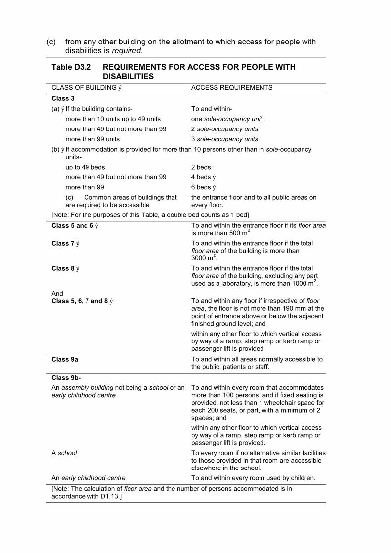
(c) from any other building on the allotment to which access for people with disabilities is required.
Table D3.2 REQUIREMENTS FOR ACCESS FOR PEOPLE WITH DISABILITIES
CLASS OF BUILDING ý ACCESS REQUIREMENTS
Class 3
(a) ý If the building contains- To and within-
more than 10 units up to 49 units one sole-occupancy unit
more than 49 but not more than 99 2 sole-occupancy units
more than 99 units 3 sole-occupancy units
(b) ý If accommodation is provided for more than 10 persons other than in sole-occupancy units-
up to 49 beds 2 beds
more than 49 but not more than 99 4 beds ý
more than 99 6 beds ý
(c) Common areas of buildings that the entrance floor and to all public areas on are required to be accessible every floor.
[Note: For the purposes of this Table, a double bed counts as 1 bed]
Class 5 and 6 ý To and within the entrance floor if its floor area is more than 500 m2
Class 7 ý To and within the entrance floor if the total floor area of the building is more than 3000 m2 .
Class 8 ý To and within the entrance floor if the total floor area of the building, excluding any part used as a laboratory, is more than 1000 m2 .
And Class 5, 6, 7 and 8 ý To and within any floor if irrespective of floor
area, the floor is not more than 190 mm at the point of entrance above or below the adjacent finished ground level; and
within any other floor to which vertical access by way of a ramp, step ramp or kerb ramp or passenger lift is provided
Class 9a
Class 9b-
An assembly building not being a school or an early childhood centre
A school
An early childhood centre
To and within all areas normally accessible to the public, patients or staff.
To and within every room that accommodates more than 100 persons, and if fixed seating is provided, not less than 1 wheelchair space for each 200 seats, or part, with a minimum of 2 spaces; and
within any other floor to which vertical access by way of a ramp, step ramp or kerb ramp or passenger lift is provided.
To every room if no alternative similar facilities to those provided in that room are accessible elsewhere in the school.
To and within every room used by children.
[Note: The calculation of floor area and the number of persons accommodated is in accordance with D1.13.]

D3.3 Parts of buildings to be accessible (a) ý Access for people with disabilities must be provided-
(i) ý from the doorway at the entrance floor providing access to any sanitary compartment required for the use of people with disabilities; and
(ii) ý to areas normally used by the occupants, excluding any plantroom, commercial kitchen, cleaners' store room, maintenance accessway, rigging loft, or the like.
(b) ý A path of travel providing required access must not include a stairway, turnstile, revolving door, escalator or other impediment which would prevent a person in a wheelchair using it.
(c) ý Access, finishes and fittings, including passageways, ramps, step ramps or kerb ramps, passenger lifts, signs, doorways and other parts of the building required by this Part must comply at least with the provisions of AS 1428.1, excluding any references within that Standard to AS 1735.12.
D3.4 Concessions It is not necessary to provide access for people with disabilities-
(a) ý to more than 30% of the public space in a restaurant, cafe, bar, function room, or the like, in a Class 6 or Class 9b building; or
(b) ý to a mezzanine floor or other space not regarded as a storey by definition; or
(c) ý to more than 1 car parking space for each 100 spaces in a public carpark; or
(d) ý to any area if access would be inappropriate because of the particular purpose for which the area is used.
************************************************************************************************
SECTION E SERVICES AND EQUIPMENT
CONTENTS
E1 Fire Fighting Equipment E1.1 Application of Part
E1.2 Fire mains and water supply services
E1.3 Fire hydrants
E1.4 Hose reels
E1.5 Sprinklers
E1.6 Portable fire extinguishers
E1.7 Fire and smoke alarms
E1.8 Fire control centres
E1.9 Fire precautions during construction
E1.10 Provision for special hazards
E2 Smoke Control E2.1 Smoke control
E2.2 Exclusion of smoke from fire-isolated exits
E2.3 Natural smoke venting
E2.4 Air-handling systems
E2.5 Roof vents
E2.6 Smoke exhaust systems
E2.7 Pressurisation systems
E3 Lift Installations E3.1 Application of Part
E3.2 Stretcher facility in lifts
E3.3 Warning against use of lifts in fire
E3.4 Emergency lifts
E4 Emergency Lighting, Exit Signs and Warning Systems E4.1 Application of Part
E4.2 Emergency lighting requirements
E4.3 Measurement of distance
E4.4 Design and operation of emergency lighting
E4.5 Exit signs
E4.6 Direction signs
E4.7 Class 2, 3 and 4 buildings: Exemptions

E4.8 Design and operation of exit signs ý
E4.9 Emergency warning and intercommunication systems ý
E5 Maintenance of safety installations E5.1 Application ý
E5.2 Maintenance requirements ý
Specifications E1.2 Fire Mains and Water Supply Services ý
E1.5 Fire Sprinkler Systems ý
E1.7 Fire Detection and Alarm Systems ý
E1.8 Fire Emergency Control Centres ý
E2.4 Smoke Control in Multistorey Buildings ý
E2.6 Smoke Exhaust Systems ý

OBJECTIVE A building must be so designed and constructed that the following objectives are fulfilled:
Part E1 Fire Fighting Equipment Having regard to the size and use of the building and its Type of construction, adequate inbuilt and external fire protection services must be provided to-
(a) ý restrict fire growth to the compartment of origin;
(b) ý facilitate the fighting of fire to minimise damage to the building and its contents; and
(c) ý prevent fire spread to adjoining buildings or allotments.
Part E2 Mechanical Ventilation and Smoke Control Air-handling systems installed in a building must-
(a) ý provide suitable air for the health and safety of the occupants; and
(b) ý incorporate adequate measures to minimise the spread of smoke in the event of fire to escape paths from the building, to other compartments remote from the fire and to assist access by the attending Fire Brigade.
Part E3 Lift Installations Suitable lifts must be provided in tall buildings, having regard to the nature of any emergency-
(a) ý to assist in the evacuation of the occupants; and
(b) ý to facilitate access by fire-fighting and other emergency personnel.
Part E4 Emergency Lighting, Exit Signs and Warning Systems (a) ý Emergency lighting and exit signs must be provided where necessary to
facilitate safe egress in an emergency upon failure of the normal lighting.
(b) ý Suitable warning and communication systems must be provided where necessary to alert occupants of any emergency, initiate automatic counter measures and summon emergency personnel.
Part E5 Maintenance Equipment, installations and components critical to the safety of the building or the occupants must be adequately maintained in such condition that will enable their proper performance.
PART E1 FIRE FIGHTING EQUIPMENT
E1.1 Application of Part This Part does not apply to a Class 1 or Class 10 building.

E1.2 Fire mains and water supply services A fire main and water supply system for fire-fighting purposes must-
(a) ý comply with Specification E1.2;
(b) ý connect all required hydrants, hose reels, water storage tanks and sprinkler systems;
(c) ý be augmented by fixed on-site fire pumps or water storage tanks if the water supply is not sufficient to provide the required pressure and flow quantities;
(d) ý incorporate water storage tanks if the building has an effective height of more than 25 m;
(e) ý incorporate a booster assembly suitably located and with connections for use by the attending Fire Brigade if-
(i) ý required to be augmented by fixed on-site fire pumps, suction or elevated tanks; or
(ii) ý more than 6 external hydrants are required at ground level; or
(iii) ý the floor area of any fire compartment exceeds 2000 m2; and
(f) ý in a building with an effective height more than 75 m, have-
(i) ý connections in each hydrant rising main for a Fire Brigade portable relay boost pump spaced at not more than 50 m in the height of the rising main;
(ii) ý a clear level space not less than 1 m wide and 2 m2 in floor area adjacent to each connection; and
(iii) ý a fire service relay pump exhaust outlet at each connection.
E1.3 Fire hydrants (a) ý One or more hydrants must be provided-
(i) ý if the building has a floor area more than 500 m2 but not more than 1000 m2 and the main entrance to the building is more than 90 m from an external hydrant;
(ii) ý if the building has a floor area more than 1000 m2 and any part of the floor of the building is more than 60 m from an external hydrant;
(iii) ý on each level if the building contains more than 4 storeys of Class 2 or more than 3 storeys of Class 3 to 9, except that an internal hydrant may serve a sole-occupancy unit of not more than 2 storeys or a unit with a mezzanine if the hydrant is located at the level of egress from that unit; and
(iv) ý at the level of the roof if the building has a rise of more than 6 storeys, except in the case of an open spectator stand, a roof having a pitch of more than 10o or a roof of a plantroom or other subsidiary structure on the roof.
(b) ý External hydrants must-
(i) ý be located not more than 20 m unobstructed distance from hard standing access for a fire pump appliance;
(ii) ý have 2 outlets on every stand-pipe or pillar hydrant; and
(iii) ý be located not closer than 6 m from a building unless protected from it with a wall having an FRL of not less than 90/90/30 extending at least 2 m each side and 3 m above the hydrant outlets.
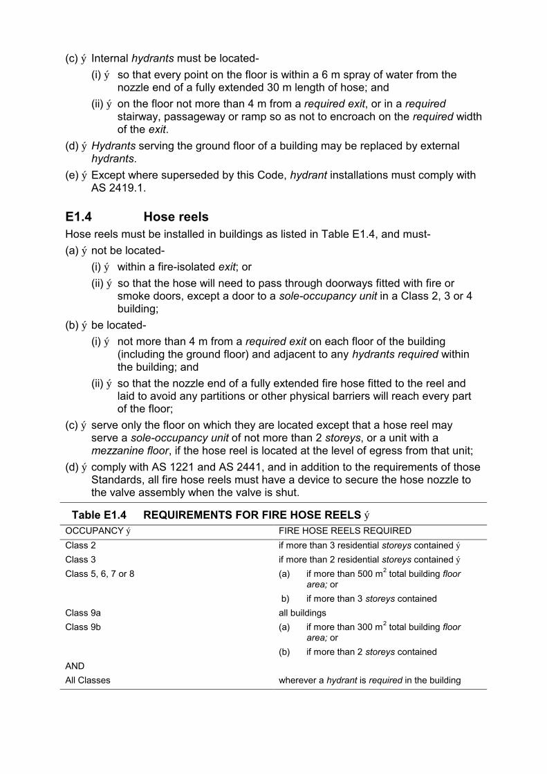
(c) ý Internal hydrants must be located-
(i) ý so that every point on the floor is within a 6 m spray of water from the nozzle end of a fully extended 30 m length of hose; and
(ii) ý on the floor not more than 4 m from a required exit, or in a required stairway, passageway or ramp so as not to encroach on the required width of the exit.
(d) ý Hydrants serving the ground floor of a building may be replaced by external hydrants.
(e) ý Except where superseded by this Code, hydrant installations must comply with AS 2419.1.
E1.4 Hose reels Hose reels must be installed in buildings as listed in Table E1.4, and must-
(a) ý not be located-
(i) ý within a fire-isolated exit; or
(ii) ý so that the hose will need to pass through doorways fitted with fire or smoke doors, except a door to a sole-occupancy unit in a Class 2, 3 or 4 building;
(b) ý be located-
(i) ý not more than 4 m from a required exit on each floor of the building (including the ground floor) and adjacent to any hydrants required within the building; and
(ii) ý so that the nozzle end of a fully extended fire hose fitted to the reel and laid to avoid any partitions or other physical barriers will reach every part of the floor;
(c) ý serve only the floor on which they are located except that a hose reel may serve a sole-occupancy unit of not more than 2 storeys, or a unit with a mezzanine floor, if the hose reel is located at the level of egress from that unit;
(d) ý comply with AS 1221 and AS 2441, and in addition to the requirements of those Standards, all fire hose reels must have a device to secure the hose nozzle to the valve assembly when the valve is shut.
Table E1.4 REQUIREMENTS FOR FIRE HOSE REELS ý OCCUPANCY ý FIRE HOSE REELS REQUIRED
Class 2 if more than 3 residential storeys contained ý
Class 3 if more than 2 residential storeys contained ý
Class 5, 6, 7 or 8 (a) if more than 500 m2 total building floor area; or
b) if more than 3 storeys contained
Class 9a all buildings
Class 9b (a) if more than 300 m2 total building floor area; or
(b) if more than 2 storeys contained
AND
All Classes wherever a hydrant is required in the building
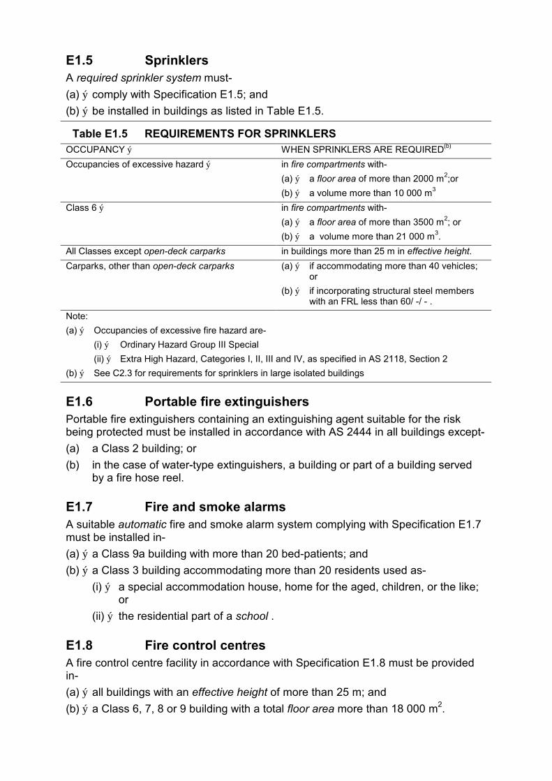
E1.5 Sprinklers A required sprinkler system must-
(a) ý comply with Specification E1.5; and
(b) ý be installed in buildings as listed in Table E1.5.
Table E1.5 REQUIREMENTS FOR SPRINKLERS OCCUPANCY ý WHEN SPRINKLERS ARE REQUIRED(b)
Occupancies of excessive hazard ý in fire compartments with-
(a) ý a floor area of more than 2000 m2;or
(b) ý a volume more than 10 000 m3
Class 6 ý in fire compartments with-
(a) ý a floor area of more than 3500 m2; or
(b) ý a volume more than 21 000 m3.
All Classes except open-deck carparks in buildings more than 25 m in effective height.
Carparks, other than open-deck carparks (a) ý if accommodating more than 40 vehicles; or
(b) ý if incorporating structural steel members with an FRL less than 60/ -/ - .
Note:
(a) ý Occupancies of excessive fire hazard are-
(i) ý Ordinary Hazard Group III Special
(ii) ý Extra High Hazard, Categories I, II, III and IV, as specified in AS 2118, Section 2
(b) ý See C2.3 for requirements for sprinklers in large isolated buildings
E1.6 Portable fire extinguishers Portable fire extinguishers containing an extinguishing agent suitable for the risk being protected must be installed in accordance with AS 2444 in all buildings except-
(a) a Class 2 building; or
(b) in the case of water-type extinguishers, a building or part of a building served by a fire hose reel.
E1.7 Fire and smoke alarms A suitable automatic fire and smoke alarm system complying with Specification E1.7 must be installed in-
(a) ý a Class 9a building with more than 20 bed-patients; and
(b) ý a Class 3 building accommodating more than 20 residents used as-
(i) ý a special accommodation house, home for the aged, children, or the like; or
(ii) ý the residential part of a school .
E1.8 Fire control centres A fire control centre facility in accordance with Specification E1.8 must be provided in-
(a) ý all buildings with an effective height of more than 25 m; and
(b) ý a Class 6, 7, 8 or 9 building with a total floor area more than 18 000 m2.
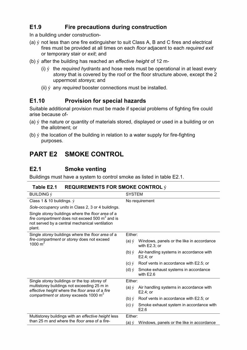
E1.9 Fire precautions during construction In a building under construction-
(a) ý not less than one fire extinguisher to suit Class A, B and C fires and electrical fires must be provided at all times on each floor adjacent to each required exit or temporary stair or exit; and
(b) ý after the building has reached an effective height of 12 m-
(i) ý the required hydrants and hose reels must be operational in at least every storey that is covered by the roof or the floor structure above, except the 2 uppermost storeys; and
(ii) ý any required booster connections must be installed.
E1.10 Provision for special hazards Suitable additional provision must be made if special problems of fighting fire could arise because of-
(a) ý the nature or quantity of materials stored, displayed or used in a building or on the allotment; or
(b) ý the location of the building in relation to a water supply for fire-fighting purposes.
PART E2 SMOKE CONTROL
E2.1 Smoke venting Buildings must have a system to control smoke as listed in table E2.1.
Table E2.1 REQUIREMENTS FOR SMOKE CONTROL ý BUILDING ý SYSTEM
Class 1 & 10 buildings. ý No requirement
Sole-occupancy units in Class 2, 3 or 4 buildings.
Single storey buildings where the floor area of a fire compartment does not exceed 500 m2 and is not served by a central mechanical ventilation plant.
Single storey buildings where the floor area of a Either: fire-compartment or storey does not exceed (a) ý Windows, panels or the like in accordance 1000 m2
with E2.3; or
(b) ý Air-handling systems in accordance with E2.4; or
(c) ý Roof vents in accordance with E2.5; or
(d) ý Smoke exhaust systems in accordance with E2.6
Single storey buildings or the top storey of Either: multistorey buildings not exceeding 25 m in (a) ý Air handling systems in accordance with effective height where the floor area of a fire E2.4; or compartment or storey exceeds 1000 m2
(b) ý Roof vents in accordance with E2.5; or
(c) ý Smoke exhaust system in accordance with E2.6
Multistorey buildings with an effective height less Either: than 25 m and where the floor area of a fire- (a) ý Windows, panels or the like in accordance
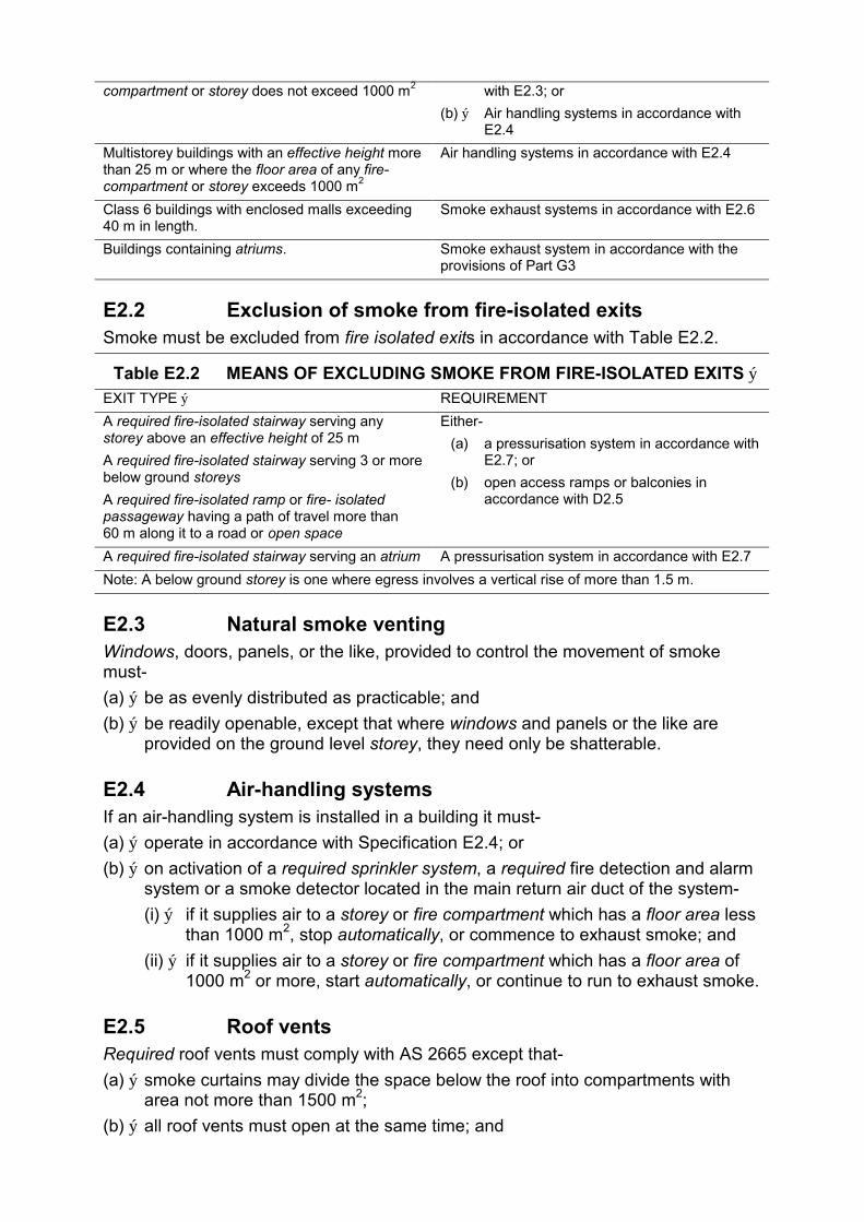
compartment or storey does not exceed 1000 m2 with E2.3; or
(b) ý Air handling systems in accordance with E2.4
Multistorey buildings with an effective height more Air handling systems in accordance with E2.4 than 25 m or where the floor area of any fire-compartment or storey exceeds 1000 m2
Class 6 buildings with enclosed malls exceeding Smoke exhaust systems in accordance with E2.6 40 m in length.
Buildings containing atriums. Smoke exhaust system in accordance with the provisions of Part G3
E2.2 Exclusion of smoke from fire-isolated exits Smoke must be excluded from fire isolated exits in accordance with Table E2.2.
Table E2.2 MEANS OF EXCLUDING SMOKE FROM FIRE-ISOLATED EXITS ý EXIT TYPE ý REQUIREMENT
A required fire-isolated stairway serving any Either-storey above an effective height of 25 m (a) a pressurisation system in accordance with A required fire-isolated stairway serving 3 or more E2.7; or below ground storeys (b) open access ramps or balconies in A required fire-isolated ramp or fire- isolated accordance with D2.5 passageway having a path of travel more than 60 m along it to a road or open space
A required fire-isolated stairway serving an atrium A pressurisation system in accordance with E2.7
Note: A below ground storey is one where egress involves a vertical rise of more than 1.5 m.
E2.3 Natural smoke venting Windows, doors, panels, or the like, provided to control the movement of smoke must-
(a) ý be as evenly distributed as practicable; and
(b) ý be readily openable, except that where windows and panels or the like are provided on the ground level storey, they need only be shatterable.
E2.4 Air-handling systems If an air-handling system is installed in a building it must-
(a) ý operate in accordance with Specification E2.4; or
(b) ý on activation of a required sprinkler system, a required fire detection and alarm system or a smoke detector located in the main return air duct of the system-
(i) ý if it supplies air to a storey or fire compartment which has a floor area less than 1000 m2, stop automatically, or commence to exhaust smoke; and
(ii) ý if it supplies air to a storey or fire compartment which has a floor area of 1000 m2 or more, start automatically, or continue to run to exhaust smoke.
E2.5 Roof vents Required roof vents must comply with AS 2665 except that-
(a) ý smoke curtains may divide the space below the roof into compartments with area not more than 1500 m2;
(b) ý all roof vents must open at the same time; and
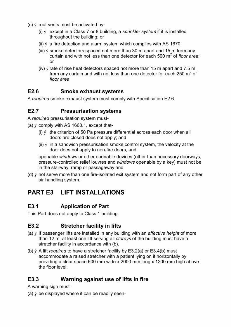
(c) ý roof vents must be activated by-
(i) ý except in a Class 7 or 8 building, a sprinkler system if it is installed throughout the building; or
(ii) ý a fire detection and alarm system which complies with AS 1670;
(iii) ý smoke detectors spaced not more than 30 m apart and 15 m from any curtain and with not less than one detector for each 500 m2 of floor area; or
(iv) ý rate of rise heat detectors spaced not more than 15 m apart and 7.5 m from any curtain and with not less than one detector for each 250 m2 of floor area
E2.6 Smoke exhaust systems A required smoke exhaust system must comply with Specification E2.6.
E2.7 Pressurisation systems A required pressurisation system must-
(a) ý comply with AS 1668.1, except that-
(i) ý the criterion of 50 Pa pressure differential across each door when all doors are closed does not apply; and
(ii) ý in a sandwich pressurisation smoke control system, the velocity at the door does not apply to non-fire doors, and
openable windows or other openable devices (other than necessary doorways, pressure-controlled relief louvres and windows openable by a key) must not be in the stairway, ramp or passageway and
(d) ý not serve more than one fire-isolated exit system and not form part of any other air-handling system.
PART E3 LIFT INSTALLATIONS
E3.1 Application of Part This Part does not apply to Class 1 building.
E3.2 Stretcher facility in lifts (a) ý If passenger lifts are installed in any building with an effective height of more
than 12 m, at least one lift serving all storeys of the building must have a stretcher facility in accordance with (b).
(b) ý A lift required to have a stretcher facility by E3.2(a) or E3.4(b) must accommodate a raised stretcher with a patient lying on it horizontally by providing a clear space 600 mm wide x 2000 mm long x 1200 mm high above the floor level.
E3.3 Warning against use of lifts in fire A warning sign must-
(a) ý be displayed where it can be readily seen-
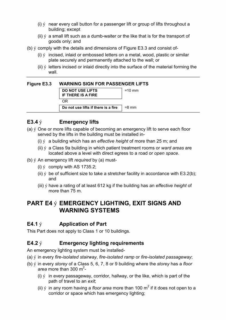
(i) ý near every call button for a passenger lift or group of lifts throughout a building; except
(ii) ý a small lift such as a dumb-waiter or the like that is for the transport of goods only; and
(b) ý comply with the details and dimensions of Figure E3.3 and consist of-
(i) ý incised, inlaid or embossed letters on a metal, wood, plastic or similar plate securely and permanently attached to the wall; or
(ii) ý letters incised or inlaid directly into the surface of the material forming the wall.
Figure E3.3 WARNING SIGN FOR PASSENGER LIFTS
DO NOT USE LIFTS =10 mm IF THERE IS A FIRE
OR
=8 mm Do not use lifts if there is a fire
E3.4 ý Emergency lifts (a) ý One or more lifts capable of becoming an emergency lift to serve each floor
served by the lifts in the building must be installed in-
(i) ý a building which has an effective height of more than 25 m; and
(ii) ý a Class 9a building in which patient treatment rooms or ward areas are located above a level with direct egress to a road or open space.
(b) ý An emergency lift required by (a) must-
(i) ý comply with AS 1735.2;
(ii) ý be of sufficient size to take a stretcher facility in accordance with E3.2(b); and
(iii) ý have a rating of at least 612 kg if the building has an effective height of more than 75 m.
PART E4 ý EMERGENCY LIGHTING, EXIT SIGNS AND WARNING SYSTEMS
E4.1 ý Application of Part This Part does not apply to Class 1 or 10 buildings.
E4.2 ý Emergency lighting requirements An emergency lighting system must be installed-
(a) ý in every fire-isolated stairway, fire-isolated ramp or fire-isolated passageway;
(b) ý in every storey of a Class 5, 6, 7, 8 or 9 building where the storey has a floor area more than 300 m2-
(i) ý in every passageway, corridor, hallway, or the like, which is part of the path of travel to an exit;
(ii) ý in any room having a floor area more than 100 m2 if it does not open to a corridor or space which has emergency lighting;

(iii) in any room having a floor area more than 300 m2;
(c) ý in every passageway, corridor, hallway, or the like, having a length of more than 6 m from the entrance doorway of any sole-occupancy unit in a Class 2 or 3 building or Class 4 part to the nearest doorway opening directly to-
(i) ý a fire-isolated stairway, fire-isolated ramp or fire-isolated passageway;
(ii) ý an external stairway serving instead of a fire-isolated stairway under D1.8; or
(iii) ý an external balcony leading to a fire-isolated stairway, fire-isolated ramp or fire-isolated passageway; or
(iv) ý a road or open space;
(d) ý in every required non-fire-isolated stairway;
(e) ý in a sole-occupancy unit in a Class 5, 6 or 9 building if-
(i) ý the floor area of the unit is more than 300 m2; and
(ii) ý an exit from the unit does not open to a road or open space or to an external stairway, passageway, balcony or ramp, leading directly to a road or open space;
(f) ý in every room or space to which there is public access in every storey in a Class 6 or 9b building where-
(i) ý the floor area in that storey is more than 300 m2;
(ii) ý any point on the floor of that storey is more than 20 m from the nearest doorway opening directly to a stairway, ramp, passageway, road or open space;
(iii) ý egress from that storey involves a vertical rise within the building of more than 1.5 m, or any vertical rise if the storey concerned does not admit sufficient light; or
(iv) ý the storey provides a path of travel from any other storey required by (i), (ii) or (iii) to have emergency lighting;
(g) ý in a Class 9a building-
(i) ý in every passageway, corridor, hallway, or the like, serving a ward area or patient treatment room having a floor area of more than 120 m2; and
(h) ý in every required fire control centre.
E4.3 Measurement of distance Distances, other than vertical rise, must be the shortest measurement along the corridor or path of travel by straight lines, curves or a combination of both.
E4.4 Design and operation of emergency lighting (a) ý Every emergency lighting system must-
(i) ý be automatic in operation;
(ii) ý provide sufficient illumination without undue delay for safe evacuation of all areas of the building where it is required;
(iii) ý if it is a central system, be suitably protected from damage by fire.
(b) ý Emergency lighting in accordance with AS 2293.1 satisfies (a).

E4.5 Exit signs Exit signs must be installed and be clearly visible to persons approaching the exit, on or near-
(a) ý every door providing direct egress from a storey to-
(i) ý an enclosed stairway, passageway or ramp serving as a required exit;
(ii) ý an external stairway, passageway or ramp serving as a required exit; and
(iii) ý an external access balcony leading to a required exit;
(b) ý every door from an enclosed stairway, passageway or ramp at every level of discharge to a road or open space;
(c) ý every horizontal exit; and
(d) ý every door serving as, or forming part of, a required exit.
E4.6 Direction signs If the exits will not otherwise be not readily apparent to persons occupying or visiting the building, exit signs with directional arrows must be installed in appropriate positions in corridors, hallways, lobbies, and the like, indicating the direction to a required exit.
E4.7 Class 2 and 3 buildings and Class 4 parts: Exemptions E4.5 does not apply to-
(a) ý a Class 2 building in which every door referred to is clearly and legibly labelled on the side remote from the exit or balcony-
(i) ý with the word "EXIT" in capital letters 25 mm high in a colour contrasting with that of the background; or
(ii) ý by some other suitable method; and
(b) ý an entrance door of a Class 2, 3 or 4 sole-occupancy unit.
E4.8 Design and operation of exit signs (a) ý Every required exit sign must-
(i) ý be clear and legible and have letters and symbols of adequate size;
(ii) ý be illuminated at a level sufficient for it to be clearly visible at all times when the building is occupied by any person having the right of legal entry to the building;
(iii) ý be installed so that if the normal power supply fails, emergency ý illumination is provided to the sign; and ý
(iv) ý if illuminated by an emergency lighting system incorporating wiring and a power source, comply with E4.4.
(b) ý Exit signs in accordance with AS 2293.1 satisfy (a).
E4.9 Emergency warning and intercommunication systems An emergency warning and intercommunication system complying where applicable with AS 2220 must be installed-
(a) ý in a building with an effective height of more than 25 m;
(b) ý in a Class 3 building having a rise of more than 2 storeys and used as a special accommodation house or home for the aged, children, or the like, or as a residential part of a school;
(c) ý in a Class 9a building having a floor area of more than 1000 m2 or a rise of more than 2 storeys; and
(d) ý in a Class 9b building-
(i) ý used as a school and having a rise of more than 3 storeys; or
(ii) ý used as a theatre, public hall, or the like, having a floor area more than 1000 m2 or a rise of more than 2 storeys.
PART E5 MAINTENANCE OF SAFETY INSTALLATIONS
E5.1 Application This Part does not apply to a Class 1 or Class 10 building.
E5.2 Maintenance requirements Safety installations in buildings must be adequately maintained.
SPECIFICATION E1.2 ýFIRE MAINS AND WATER SUPPLY SERVICES
1. ý Scope This Specification refers to fire mains and water supply services for fire-fighting equipment in buildings.
2. ý General requirements A fire main must-
(a) ý be capable of supplying water at the flow rates and pressures necessary for the satisfactory operation of the required fire-fighting equipment;
(b) ý not to incorporate plastic pipes; and
(c) ý not be used for other than fire-fighting purposes, except a fire main serving only hose reels which may be connected to a metered supply if-
(i) ý the required flow rate and pressure can be maintained at the most hydraulically disadvantaged hose reel;
(ii) ý the water meter and street supply to the allotment have a nominal diameter of not less than 32 mm;
(iii) ý water supply pipework reticulation arrangements comply with Figure 2; and
(iv) ý any system valve which can isolate flow in the fire main is secured in the open position by a padlocked metal strap and has attached an engraved non-ferrous metal tag with 8 mm upper case wording:
FIRE SERVICE VALVE-
CLOSE ONLY TO SERVICE FIRE HOSE REELS.

Figure 2 WATER SUPPLY RETICULATION: COMBINED SERVICES ý
stopcock
3. ý Fixed on site fire pumps Fixed on site fire pumps must-
(a) ý comprise a minimum of 2 pumps, except in a Class 2, 3 or 5 building one pump may be used if the building-
(i) ý has an effective height of not more than 25 m; and
(ii) ý contains fire compartments not more than 2000 m2 in floor area; and
(b) ý be located in a room or enclosure which has an FRL of not less than 120/120/60 and is-
(i) ý within the building; or
(ii) ý external within 6 m of the building but not closer than 6 m to any fire-source feature.
4. ý Booster connections and cabinets (a) ý Each booster inlet connection must-
(i) ý allow a fire main to be pressurised without the need to manually operate valves; and
(ii) ý if fitted with a pressure gauge, the gauge must comply with AS 1349, and have a full scale reading of not less than 25% more than the pressure to which the system has been hydrostatically tested.
(b) ý Cabinets may be located-
(i) ý at the external wall of a building if they are within sight of the main entrance and for Class 6, 7, 8 or 9b buildings, separated from the building by construction having an FRL of not less than 120/120/60 for not less than 2 m each side of and above the top of the cabinet; or
(ii) ý remote from the building if they are at the boundary of the allotment, within sight of the main entrance to the building, adjacent to the principle vehicular access to the allotment and located not less than 10 m from the external wall of any building; or
(iii) ý in any other suitable position.
(c) ý A permanent fade and water resistant plan, equal to photo-engraved anodized aluminium, must be displayed in a prominent position within the cabinet, showing the following information:
(i) ý the layout of the building and adjacent streets; and
(ii) ý the layout of the fire hydrant system reticulation, with supply authority street mains and size, location of street and allotment hydrants, fire hose reels, booster connections, street and allotment isolating and non-return valves, pumps and tanks; and
(iii) ý the operational discharge pressure and pressure at zero flow of any pump installed in the system; and
(iv) ý the capacity of any tank connected to the system; and
(v) ý the height of the highest hydrant outlet above the lowest booster inlet connection; and
(vi) ý the year of installation of the system.
(d) ý Provision must be made for the drainage of water from within a booster cabinet by-
(i) ý standing the cabinet on legs with a 50 mm clearance to a concrete plinth; and
(ii) ý sloping the floor not less than 75 mm from the rear of the cabinet to drainage weepholes at the front or to the outside.
SPECIFICATION E1.5 FIRE SPRINKLER SYSTEMS
1. ý Scope This specification sets out requirements for the design and installation of automatic fire sprinkler systems.
2. ý Adoption of AS 2118 An automatic fire sprinkler system must comply with AS 2118 subject to this Specification.
3. ý Provisions of AS 2118 not to apply The following provisions of AS 2118 do not apply:
(a) ý Clause 1.2.20 - definition of a "fire door".
(b) ý Clause 3.6 - "Maintenance".
4. ý Interpretation A reference in AS 2118 to-
(a) ý an "inferior wall" - means an external wall required to have an FRL and which incorporates openings; and
(b) ý a "fire door" - means a fire door complying with Specification C3.4.
5. ý Definition of a sprinklered building Notwithstanding AS 2118, a building or a part of a building is deemed to be sprinklered if-
(a) ý in the case of a whole building, the building complies with Section C of this Code and is sprinklered throughout; or
(b) ý in the case of a part of a building-
(i) ý the part is sprinklered throughout and fire-separated from the ý unsprinklered part in accordance with Part C2; and ý
(ii) ý any opening in the fire separating construction between the sprinklered and unsprinklered part is protected in accordance with Part C3.
6. ý Exemptions If a building or part of a building is required to be sprinklered throughout, the exemptions nominated in clause 3.3.3 of AS 2118 apply, except where protection of openings is specified by that clause, the protection must be by means of a fire door in accordance with Part C3 of this Code.
7. ý Fast response sprinklers Fast response sprinklers may only be installed where they have been tested for the type of application proposed and it is demonstrated that the protection provided will not be less than that provided by an AS 2118 installation.
8. ý Sprinkler valve enclosures Sprinkler alarm valves must be located in a secure enclosure or room of adequate size, and-
(a) ý where the valves are located within a building, the enclosure and required access to it, which must be from a door opening onto a public place, must be separated from all other parts of the building by construction which has an FRL of not less than 120/120/120; and
(b) ý where the valves are located external to a building, the enclosure must not be located closer than 6 m to it, unless-
(i) ý a wall having an FRL of not less than 90/90/90 is between the enclosure and the building; and
(ii) ý the wall extends to the full height and not less than 2 m each side of the enclosure; and
(iii) ý an entry door to the building is located no further than 6 m from the enclosure.
9. ý Water supply Notwithstanding AS 2118, the water supply to a required sprinkler system must be not less than-
(a) ý Grade III for buildings not more than 25 m effective height; and
(b) ý Grade I for buildings of more than 25 m effective height, except that if only a part of the building is required to be sprinklered, the grade of supply may be reduced to-
(i) ý Grade II for each part being Class 6 or Class 9, or a Class 6 or Class 9 part together with a part used as a public carpark; and
(ii) ý Grade III if only a part of the building is required to be sprinklered and it is a part used as a public carpark.

SPECIFICATION E1.7 ýFIRE DETECTION AND ALARM SYSTEMS
1. ý Scope This Specification describes the installation and operation of fire detection and alarm systems, which may also be utilised to operate a smoke control system within a building.
2. ý Adoption of AS 1670 A fire detection and alarm system must comply with AS 1670 subject to this Specification.
3. ý Purpose The purpose of a fire detection and alarm system is to-
(a) ý warn the occupants of a fire within the building; and
(b) ý alert the local Fire Brigade; and
(c) ý activate any installed automatic smoke control system.
4. ý Connection to other warning devices In addition to AS 1670, a fire detection system must be connected to-
(a) ý any emergency warning and intercommunication system required by Part E4, except in a Class 9a building, a discrete alert and evacuation tone must be employed to minimise patient trauma; or
(b) ý auxiliary warning devices strategically located throughout the premises on every floor if no emergency warning and intercommunication system is required.
5. ý Detectors in Class 9a buildings In a Class 9a building, detectors must be-
(a) ý type "A" rate of rise heat detectors throughout the building, except-
(i) ý in a sprinklered building; or
(ii) ý those areas where smoke detectors are installed; and
(b) ý smoke detectors-
(i) ý to each ward area or room which may be occupied by a sleeping, sedated or dependent patient, and the path of egress from each such room to a public space; and
(ii) ý to other areas as necessary for effective smoke control.
6. ý Location of smoke detectors Smoke detectors must be-
(a) ý wherever possible, surface mounted and external to air-conditioning and ventilation ducts, unless a point sampling system with maximum sensitivity level of 0.5% smoke obscuration per metre is used; and
(b) ý located at natural collection points for hot smoke having regard to the ceiling geometry and its effects on the migratory path; and

(c) situated not more than 3 m from smoke doors or fire doors in accordance with AS 1905.1; and
(d) ý of the photo-electric type if installed within ducts or atmospheres contaminated with sub-micron dust and other particles likely to operate an ionization type detector.
7. ý Threshold Levels (a) ý Sampling systems must comply with AS 1670, with response times and alarm
thresholds maintained at minimum levels and no alarm delay permitted on the highest alarm threshold utilised.
(b) ý The setting of alarm threshold levels for addressable detectors used within intelligent systems must not exceed the sensitivity levels nominated in-
(i) ý AS 1668.1; and
(ii) ý AS 1603 Parts 1 to 5.
SPECIFICATION E1.8 FIRE CONTROL CENTRES
1. ý Scope This Specification describes the construction and content of required fire control centres or rooms.
2. ý Purpose and content A fire control centre or room must-
(a) ý provide an area from which fire fighting operations or other emergency procedures can be directed or controlled; and
(b) ý contain controls, panels, telephones, furniture, equipment and the like associated with the required fire services in the building; and
(c) ý not be used for any purpose other than the control of-
(i) ý fire fighting activities; and
(ii) ý other measures concerning the safety or security of the building ý occupants. ý
3. ý Location of fire-control centre or room A fire control centre or room must be so located in a building that egress from any part of its floor, to a public road or open space, does not involve changes in level which in aggregate exceed 300 mm.
4. ý Construction A fire-control centre in a building more than 50 m in effective height must be in a separate room where-
(a) ý the enclosing construction is of concrete, masonry or the like, sufficiently impact resistant to withstand the impact of any likely falling debris, and with an FRL of not less than 120/120/120; and
(b) ý any material used as a finish, surface, lining or the like within the room complies with the requirements of Specification C1.10 for fire-isolated stairways; and
(c) ý services, pipes, ducts and the like that are not directly required for the proper functioning of the fire control room do not pass through it; and
(d) ý openings in the walls, floors or ceiling which separate the room from the interior of the building are confined to doorways, ventilation and other openings for services, necessary for the proper functioning of the facility.
5. ý Protection of openings Openings permitted by clause 4 must be protected as follows:
(a) ý Openings for windows, doorways, ventilation, service pipes, conduits and the like, in an external wall of the building that faces a public road or open space, must be protected in accordance with Part C3 as applicable.
(b) ý Openings in the floors, ceilings and internal walls enclosing a fire control room must, except for doorways, be protected in accordance with Part C3, as appropriate.
(c) ý A door opening in the internal walls enclosing a fire-control room, must be fitted with a self closing 120/120/30 smoke sealed fire door.
(d) ý Openings associated with natural or mechanical ventilation must-
(i) ý not be made in any ceiling or floor immediately above or below the fire control room; and
(ii) ý be protected by a 120/120/- fire damper if the opening is for a duct through a wall required to have an FRL, other than an external wall.
6. ý Exit doors (a) ý Required doors to a fire control room must open into the room, be lockable and
located so that persons using escape routes from the building will not obstruct or hinder access to the room.
(b) ý The fire control room must be accessible via two paths of travel-
(i) ý one from the front entrance of the building; and
(ii) ý one direct from a public place or fire-isolated passageway which leads to a public place and has an FRL of not less than 120/120/120.
7. ý Size and contents (a) ý A fire control room must contain not less than-
(i) ý a Fire Indicator Panel and necessary control switches and visual status indication for all required fire pumps, smoke control fans and other required fire safety equipment installed in the building; and
(ii) ý a telephone directly connected to an external telephone exchange; and
(iii) ý a blackboard or whiteboard not less than 1200 mm wide x 1000 mm high; and
(iv) ý a pin up board not less than 1200 mm wide x 1000 mm high; and
(v) ý a raked plan layout table of size not less than the plans to be laid out upon the table, and plans of the structural, architectural, electrical, mechanical, lift and fire service details which may be stored beneath the plan layout table or within other suitable storage facility located in the room.
(b) ý In addition, a fire control room may contain-

(i) ý master emergency control panels, lift annunciator panels, remote switching controls for gas or electrical supplies and emergency generator backup; and
(ii) ý building security, surveillance and management systems if they are completely segregated from all other systems.
(c) ý A fire-control room must-
(i) ý have a gross area of not less than 10 m2 and the length of any internal side must be not less than 2.5 m; and
(ii) ý if only the minimum prescribed equipment is installed - have a net floor area of not less than 8 m2 with a clear space of not less than 1.5 m2 in front of the Fire Indicator Panel; and
(iii) ý if additional equipment is installed - have an additional area of not less than 2 m2 net floor area for each additional facility and a clear space of not less than 1.5 m2 in front of each additional control or indicator panel,
and the area required for any path of travel through the room to other areas must be provided in addition to the requirements (ii) and (iii).
8. ý Ventilation and power supply A fire control room must be ventilated by-
(a) ý natural ventilation from a window or doorway in an external wall of the building which opens directly into the fire control room from a roadway or open space; or
(b) ý a pressurising system that only serves the fire control room, and-
(i) ý is installed in accordance with AS 1668.1 as though the room is a fire-isolated stairway; and
(ii) ý is activated automatically by operation of the fire alarm or sprinkler system installed in the building and manually by an over-riding control in the room; and
(iii) ý provides a flow of fresh air through the room of not less than 30 air changes per hour when the system is operating and any door to the room is open; and
(iv) ý has fans, motors and ductwork that form part of the system but not contained within the fire-control room protected by enclosing construction with an FRL of not less than 120/120/120; and
(v) ý has any electrical supply to the fire-control room or equipment necessary for its operation connected to the supply side of the main disconnection switch for the building and electrical service cables of copper-sheathed-mineral-insulated cable with copper conductors,
and no openable devices other than necessary doorways, pressure controlled relief louvres and windows, openable by a key, must be constructed in the fire control room.
9. ý Sign The external face of the door to the fire control room must have a sign with the words-
FIRE CONTROL ROOM

in letters of not less than 50 mm high and of a colour which contrasts with that of the background.
10. ý Lighting Emergency lighting in accordance with Part E4 must be provided in a fire control room, except that an illumination level of not less than 400 lux must be maintained at the surface of the plan table.
11. ý Equipment not permitted within a fire control centre or room
An internal combustion engine, pumps, sprinkler control valves, pipes and ancillary, fittings must not be located in a fire control centre or room, but may be located in rooms accessed through the fire control centre or room.
12. ý Ambient Sound Level The ambient sound level within the fire control centre or room measured when all fire safety equipment is operating in the manner in which it operates in an emergency, must not exceed 65 dB(A), when determined in accordance with AS 2107.
SPECIFICATION E2.4 ýSMOKE CONTROL IN MULTISTOREY BUILDINGS
1. ý Scope This Specification describes the performance and operation of mechanical ventilation and air-conditioning systems used to control smoke in a multistorey building.
2. ý Central air-conditioning plant The installed central air-conditioning system may be utilized for smoke control if it complies with AS 1668.1 and to achieve sandwich pressurisation-
(a) ý additional smoke control dampers may be introduced into the smoke exhaust and fresh air supply ductwork-
(i) ý in such a manner so that the fire integrity of the building is not ý compromised; and ý
(ii) ý to achieve not less than 20 Pa pressure differential between the fire affected storey and all other storeys; and
(b) ý such dampers must have a fail safe operation which-
(i) ý closes any smoke damper to the supply air to the fire-affected storey; and
(ii) ý opens any smoke damper connected to a smoke exhaust duct or relief opening which will relieve the smoke to outside or exhaust the smoke from the fire-affected storey; and
(c) ý automatic smoke dampers so employed must not be more smoke tight than traditional multi-blade volume control dampers.

3. ý Individual air-conditioning units on each floor To achieve sandwich pressurisation, where an air-handling plant is installed at each storey-
(a) ý the air-conditioning unit on the fire-affected storey must stop; and
(b) ý the air-conditioning units at all other storeys must supply full fresh air to those storeys; and
(c) ý the fire-affected storey must be relieved to outside or exhausted in accordance with Figure 2 of Specification E2.6; and
(d) ý the wiring for fans must be MIMS (copper) cabling in accordance with AS 1668.1 if it passes through other compartments which may be subject to the effect of a fire, other than the compartment in which the fan is located.
4. ý Actuation of smoke control system The smoke control system must be automatic in operation and actuated by-
(a) ý smoke detectors located adjacent to each required exit and return air path on each floor in accordance with Specification E1.7; and
(b) ý by any other suitable fire alarm system, including a sprinkler system, installed within the building.
SPECIFICATION E2.6 SMOKE EXHAUST SYSTEMS
1. ý Scope This Specification describes the performance and method of operation of smoke exhaust systems in buildings which are designed to-
(a) ý remove smoke from within the building using ducted or roof mounted exhaust fans; or
(b) ý in a shopping centre complex or mall, remove smoke from within pedestrian malls to maintain for as long as possible a tenable escape path for the occupants.
2. ý Fan capacity Fan systems must have at least an exhaust capacity in accordance with Figure 2.
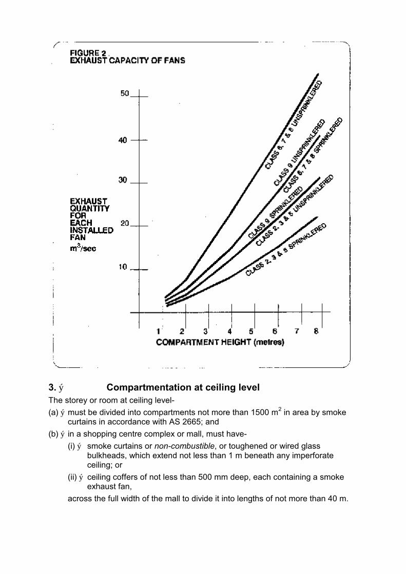
3. ý Compartmentation at ceiling level The storey or room at ceiling level-
(a) ý must be divided into compartments not more than 1500 m2 in area by smoke curtains in accordance with AS 2665; and
(b) ý in a shopping centre complex or mall, must have-
(i) ý smoke curtains or non-combustible, or toughened or wired glass bulkheads, which extend not less than 1 m beneath any imperforate ceiling; or
(ii) ý ceiling coffers of not less than 500 mm deep, each containing a smoke exhaust fan,
across the full width of the mall to divide it into lengths of not more than 40 m.

4. ý Location of fans and discharge Exhaust fans must be located so as not to cause undue turbulence, and-
(a) ý in a shopping centre complex or mall-
(i) ý be spaced no more than 40 m apart and not more than 20 m from the end of the mall; and
(ii) ý not be located at a mall intersection unless there is an open area where the ceiling is raised not less than 2 m above the ceiling in the mall; and
(iii) ý be located at natural collection points for the hot smoky gasses within each smoke compartment having regard to the ceiling geometry and its effect on the migratory path of the smoke;
(b) ý in other buildings be located so that each fan must not serve more than one 1500 m2 smoke compartment; and
(c) ý discharge directly to the outside and in a manner that will not spread fire or smoke to adjacent fire compartments or buildings.
5. ý Make-up air Low level fresh air inlet openings or doors must be sized to provide adequate low velocity fresh air make up to satisfy the exhaust performance of the installed smoke exhaust fans, care being exercised in the number and location of such openings and their disturbance of the smoke layer due to turbulence created by the incoming air.
6. ý Operation of fans All smoke exhaust fans must start sequentially and be activated by the operation in the area served by the fan of-
(a) ý a sprinkler system;
(b) ý a fire detection and alarm system which complies with Specification E1.7; or
(c) ý a detector system comprising-
(i) ý smoke detectors spaced not more than 30 m apart and 15 m from any curtain, bulkhead or wall and not less than one detector for each 500 m2
of floor area; or
(ii) ý rate of rise heat detectors spaced not more than 15 m apart and 7.5 m from any curtain, bulkhead or wall and with not less than one detector for each 250 m2 of floor area,
and not less than 2 detectors located on opposite sides of each fan inlet; or
(d) ý in a shopping centre complex or mall-
(i) ý optical smoke detectors in each smoke compartment with at least one detector for each 150 m2 or floor area, arranged in at least 2 groups so that on activation of an alarm group in the respective smoke compartment full exhaust is initiated, and on activation of a second group and following a 30 second check period an alarm is transmitted to the Fire Brigade; and
(ii) ý a manual break-glass alarm at each exit from a shop with a floor area of mote than 1000 m2 arranged to activate the exhaust system and transmit an alarm to the Fire Brigade.
7. ý Protection of wiring Power supply wiring for roof-mounted exhaust fans must be MIMS (copper) cable or otherwise suitably fire-protected where it passes through other storeys and might be affected by fire remote from the floor served by the plant.
8. ý Resistance to high temperatures If not adequately shielded from the airflow-
(a) ý all parts of exhaust fans and other equipment required to operate in a smoke laden environment; and
(b) ý parts of the building required to be smoke-resisting,
must be capable of withstanding a temperature of 200oC for a period of not less than 1 hour.
************************************************************************************************

SECTION F HEALTH AND AMENITY
CONTENTS
F1 Damp and Weatherproofing F1.1 Drainage ý
F1.2 Building on land subject to dampness ý
F1.3 Drainage of land external to building ý
F1.4 Weatherproofing of roofs and walls ý
F1.5 Roof coverings deemed-to-satisfy ý
F1.6 Pliable roof sarking ý
F1.7 Water proofing of wet areas in buildings ý
F1.8 Damp-proof courses and mortars ý
F1.9 Acceptable damp-proof courses ý
F1.10 Damp-proofing of floors on the ground ý
F2 Sanitary and Other Facilities F2.1 Facilities in residential buildings ý
F2.2 Calculation of number of occupants and fixtures ý
F2.3 Facilities in Class 3 to 9 buildings ý
F2.4 Facilities for people with disabilities ý
F2.5 Construction of sanitary compartments ý
F2.6 Interpretation: Urinals and washbasins ý
F3 Room Sizes F3.1 Height of rooms ý
F3.2 Reduced height permissible ý
F4 Light and Ventilation F4.1 Provision of natural light ý
F4.2 Methods and extent of natural lighting ý
F4.3 Natural light borrowed from adjoining room ý
F4.4 Artificial lighting ý
F4.5 Ventilation of rooms ý
F4.6 Natural ventilation ý
F4.7 Ventilation borrowed from adjoining room ý
F4.8 Restriction on position of WCs and urinals ý
F4.9 Airlocks ý
F4.10 Sub-floor ventilation ý

F4.11 Public carparks ý
F5 Noise Transmission and Insulation F5.1 Application of Part ý
F5.2 Sound Transmission Class: Interpretation ý
F5.3 Sound insulation of floors between units ý
F5.4 Sound insulation of walls between units ý
F5.5 Walls between a bathroom, laundry or kitchen and a habitable room ý in adjoining unit ý
F5.6 Soil and waste pipes to be separated ý
F5.7 Isolation of pumps ý
Specifications F5.2 STC Ratings for Building Elements ý
F5.5 Impact Sound - Test of Equivalence ý

OBJECTIVE A building must be so designed and constructed that the following objectives are fulfilled:
Part F1 Damp and Weatherproofing Suitable drainage, damp and weatherproofing must be provided where necessary to prevent-
(a) ý moisture or damp affecting the stability of the building;
(b) ý the creation of any unhealthy or dangerous condition; or
(c) ý causing undue damage to adjoining property.
Part F2 Sanitary and Other Facilities Adequate toilet and washing facilities must be provided for the occupants of a building, having regard to its use and size.
Part F3 Room Sizes The floor area, plan dimensions and ceiling height of rooms and other spaces within a building must be adequate for their use and purpose.
Part F4 Light and Ventilation The standard and light and ventilation within a building must be adequate for the occupants, having regard to the use or purpose of the building.
Part F5 Noise Transmission Adequate insulation against noise transmission must be provided to minimise undue disturbance to neighbouring occupants.
PART F1 DAMP AND WEATHERPROOFING
F1.1 Drainage The construction of a drainage system and the position and manner of discharge of a stormwater drain must not-
(a) ý result in the entry of water into a building;
(b) ý affect the stability of a building; or
(c) ý create any unhealthy or dangerous condition on the site or within the building.
F1.2 Building on land subject to dampness One or all of the following measures must be carried out if it is warranted by the dampness of the building site:
(a) ý The subsoil must be adequately drained.
(b) ý The ground under the building must be regraded or filled and provided with outlets to prevent accumulation of water.

(c) ý The surface of the ground under the building must be covered with a suitable damp-resisting material.
F1.3 Drainage of land external to building A suitable system of drainage must be provided if paving, excavation or any other work on an allotment will cause undue interference with the existing drainage of rainwater falling on the allotment whether the existing drainage is natural or otherwise.
F1.4 Weatherproofing of roofs and walls Roofs and external walls (including openings around windows and doors) must be so constructed as to prevent rain or dampness penetrating to the inner parts of a building, unless it is-
(a) ý a Class 7, 8 or 10 building and in the particular case there is no necessity for compliance;
(b) ý a garage, tool shed, sanitary compartment, or the like, forming part of a building used for other purposes; or
(c) ý an open spectator stand or open-deck carpark.
F1.5 Roof coverings deemed-to-satisfy A roof complies with F1.4 if it is covered with-
(a) ý concrete roofing tiles that comply with AS 1757 or AS 1759 and are fixed, except in cyclonic areas, in accordance with AS 1758 or AS 1760, as appropriate;
(b) ý terracotta roofing tiles that comply with AS 2049 and are fixed, except in cyclonic areas, in accordance with AS 2050;
(c) ý corrugated cellulose fibre reinforced cement sheeting that complies with AS 2908; or
(d) ý metal sheet roofing without transverse laps that complies with AS 1562.
F1.6 Pliable roof sarking Pliable roof sarking used under roof or wall coverings must comply and be fixed in accordance with-
(a) ý AS 1736; or
(b) ý AS 1903 and AS 1904.
F1.7 Water proofing of wet areas in buildings The following parts of a building must be impervious to water:
(a) ý In any building - the floor surface or substrate in a shower enclosure, or within 1.5 m measured horizontally from a point vertically below the shower fitting, if there is no enclosure.
(b) ý In a Class 3, 5, 6, 7, 8 or 9 building - the floor surface or substrate in a bathroom or shower room, slop hopper or sink compartment, laundry or sanitary compartment which is used in common by the occupants.
(c) ý The wall surface or substrate-
(i) ý of a shower enclosure, or if the shower is not enclosed, within 1.5 m and exposed to a shower fitting, to a height of 1.8 m above the floor;
(ii) ý immediately adjacent or behind a bath, trough, basin, sink, or similar fixture, to a height of 300 mm above the fixture if it is within 75 mm of the wall.
(d) ý The junction between the floor and wall if the wall and floor are required to be impervious to water.
(e) ý The junction between the wall and fixture if the wall is required to be impervious to water.
F1.8 Damp-proof courses and mortars Except in a building that is exempt from weatherproofing under F1.4, moisture from the ground must be prevented from reaching-
(a) ý the lowest floor timbers and the walls above the lowest floor joists;
(b) ý the walls above the damp-proof course; and
(c) ý the underside of a suspended floor constructed of a material other than timber, and the supporting beams or girders.
F1.9 Acceptable damp-proof courses A damp-proof course must consist of-
(a) ý a material that complies with AS 2904; or
(b) ý suitable termite shields placed on piers; or
(c) ý other suitable material.
F1.10 Damp-proofing of floors on the ground If a floor of a room is laid on the ground or on filling-
(a) ý moisture from the ground must be prevented from reaching the upper surface of the floor and adjacent walls by-
(i) ý the insertion of a vapour barrier in accordance with AS 2870.1; or
(ii) ý other suitable means;
(b) ý damp-proofing need not be provided if-
(i) ý the building is exempt from weatherproofing under F1.4; or
(ii) ý the floor is the base of a stair, lift or similar shaft which is adequately drained by gravitation or mechanical means.
PARTF2 SANITARY AND OTHER FACILITIES
F2.1 Facilities in residential buildings Sanitary and other facilities for Class 1, 2 and 3 buildings and for Class 4 parts of buildings must be provided in accordance with Table F2.1.
Table F2.1 PROVISION OF SANITARY AND OTHER FACILITIES IN RESIDENTIAL BUILDINGS
CLASS OF MINIMUM FACILITIES REQUIRED BUILDING

Class 1 ý (a) a kitchen sink and facilities for the preparation and cooking of food;
(b) ý a bath or shower;
(c) ý clothes washing facilities, comprising at least one washtub and space in the same room for a washing machine or wash copper; and
(d) ý a closet pan and washbasin
If any of these facilities are detached from the main building, they must be set aside for the exclusive use of the occupants of the Class 1 building.
Class 2 ý Within each sole-occupancy unit-
(a) ý a kitchen sink and facilities for the preparation and cooking of food;
(b) ý a bath or shower; and
(c) a closet pan and washbasin; and
For each building-
(a) ý a separate laundry for each 4 sole-occupancy units, or part, without its own clothes washing facilities comprising at least one washtub and space for a washing machine or wash copper;
(b) ý clothes drying facilities comprising-
(i) ý lines or clothes hoists with not less than 7.5 m of line per sole-occupancy unit; or
(ii) ý one heat-operated drying cabinet or appliance for each 4 sole-occupancy units, or part, without its own drying facilities; and
Facilities for employees-
(c) ý if the building contains more than 10 sole-occupancy-units, or a group of Class 2 buildings on the one allotment contains, in total, more than 10 sole-occupancy units - a closet pan and washbasin in a compartment or room at or near ground level and accessible to employees without entering a sole-occupancy unit.
Class 3 ý Facilities for residents-
For each building or group of buildings-
(a) ý a bath or shower; and
(b) ý a closet pan and washbasin,
for each 10 residents for whom private facilities are not provided, except that-
(c) ý if one urinal is provided for each 25 males up to 50 and one additional urinal for each additional 50 males or parts thereof,
one closet pan for each 12 males may be provided.
Note: These facilities need not be situated within the building.
Class 4 ý For each sole-occupancy unit-
(a) ý a kitchen sink and facilities for the preparation and cooking of food;
(b) ý a bath or shower;
(c) ý a closet pan and washbasin;
(d) ý clothes washing facilities, comprising a washtub and space in the same room for a washing machine or wash copper; and
(e) ý a clothes line or hoist, or space for a heat-operated drying cabinet or similar appliance for the exclusive use of the occupants.
F2.2 ý Calculation of number of occupants and fixtures (a) ý The number of persons accommodated must be calculated according to Table
D1.13 if it cannot be more accurately determined by other means.
(b) ý Unless the premises are used predominantly by one sex, sanitary facilities must be provided on the basis of equal numbers of males and females.

F2.3 Facilities in Class 3 to 9 buildings Sanitary facilities must be provided in Class 3, 5, 6, 7, 8 and 9 buildings in accordance with Table F2.3.
Table F2.3 SANITARY FACILITIES IN CLASS 3, 5, 6, 7, 8 AND 9 BUILDINGS Class of Building
User Max Number Served by-
Closet Fixture(s) Urinal(s) Washbasin(s)
1 2 Each Extra
1 2 Each Extra
1 2 Each Extra
3,5,6 and 9 other than schools
Employees
Males 20 40 20 25 50 50 30 60 30
Females 15 30 15 30 60 30
7 and 8 Employees Males 20 40 20 25 50 50 20 40 20
Females 15 30 15 20 40 20
6-Department stores, shopping centres
Patrons
Males Females
1200 300
2400 600
1200 1200
600 1200 1200 600 600
1200 1200
1200 1200
6-Restaurants cafes, bars, public halls, function rooms
Patrons
Males Females
100 25
300 50
200 **50
50 100 *50 50 50
200 150
200 200
*Where the number of male patrons exceeds 250, not less than 5 urinals must be provided plus one additional urinal for every additional 100 males in excess of 250.
**Where the number of female patrons exceeds 250, not less than 6 closet fixtures must be provided plus one additional closet fixture for every 100 females in excess of 250
9a- Health-care buildings
Patients-
Males Females
--
16 16
8 8
8 8
16 16
8 8
- Other facilities (i) One shower for each 8, or part, patients or inmates.
(ii) One island-type plunge bath in each storey containing a ward area.
9b - Schools not being early childhood centres
Staff and Employees-
Males Females
20 5
40 20
20 15
20 45 30 30 30
60 60
30 30
Students-
Males Females
30 10
70 20
70 20
30 70 35 20 20
40 40
40 40
9b-Early childhood centres
Children- 30 15 30 15
Other facilities One bath or shower-bath must be provided.
9b- Sporting Participants venues, theatres, Males 20 40 20 10 20 10 10 20 10 cinemas, art Females 10 20 10 10 20 10 galleries or the like
Other facilities One shower for each 10, or part, participants.
Spectators or patrons
Males Females
250 75
500 150
500 75
100 200 100 150 150
300 300
150 150
9b- Churches, chapels or the like
Patrons
Males Females
300 150
800 300
500 150
200 400 200 250 250
500 500
250 250
F2.4 Facilities for people with disabilities Sanitary facilities must be provided in accordance with Table F2.4 in every Class 3, 5, 6, 7, 8 and 9 building that is required by Part D3 to be accessible to people with disabilities.
Table F2.4 SANITARY FACILITIES FOR PEOPLE WITH DISABILITIES ý CLASS OF BUILDING MINIMUM FACILITY FOR USE BY PEOPLE WITH DISABILITIES
Class 3 - In every sole-occupancy unit to which access for people with disabilities is required -
(a) ý one closet pan and washbasin; and
(b) ý one shower-bath.
Class 5, 6, 7, 8 and 9 buildings with floor area more than 500 m2 and
Class 3 if accommodation is other than in sole-occupancy units or other parts of the building are required to be accessible-
TOTAL FACILITIES NORMALLY MINIMUM NUMBER FOR USE BY PEOPLE WITH DISABILITIES REQUIRED
Closet pans plus urinals-
1 - 100 (a) one unisex facility; or
(b) one closet pan and washbasin for each sex.
101 - 200 (a) 2 unisex facilities; or
(b) one closet pan and washbasin for each sex and one unisex facility
More than 200 (a) 2 unisex facilities or one closet pan and washbasin for each sex and one unisex facility; and
(b) one additional unisex facility or one closet pan and washbasin for each sex for each additional 100 facilities normally required.
In all cases, facilities for females must include adequate means for the disposal of sanitary towels.
Baths or showers one shower or shower-bath for each 10 or part, but not less than one for use by both sexes.
F2.5 Construction of sanitary compartments (a) ý Partitions - Other than in an early childhood centre, sanitary compartments
must have doors and partitions that must separate adjacent compartments and extend-
(i) ý from floor level to the ceiling in the case of a unisex facility; or
(ii) ý to a height of not less than 1500 mm above the floor if primary school children are the principal users; or 1800 mm above the floor in all other cases.
(b) ý Facilities for people with disabilities - The construction and layout of sanitary compartments for use by people with disabilities must comply with AS 1428.1.
F2.6 Interpretation: Urinals and washbasins (a) ý A urinal may be either-
(i) ý an individual stall or wall-hung urinal;
(ii) ý each 600 mm length of a continuous urinal trough; or
(iii) ý a closet pan used in place of a urinal.
(b) ý A washbasin may be-
(i) ý an individual basin; or
(ii) ý a part of a hand washing trough served by a single water tap.
PART F3 ROOM SIZES
F3.1 Height of rooms Minimum ceiling heights are:
(a) ý Class 1, 2, or 3 buildings, or Class 4 parts-
(i) ý habitable room excluding a kitchen - 2.4 m;
(ii) ý kitchen, laundry, or the like - 2.1 m;
(iii) ý corridor or passageway - 2.1 m.
(b) ý Class 5, 6, 7 and 8 buildings -
(i) ý office, shop, warehouse or factory space - 2.4 m;
(ii) ý corridor, passageway, or the like - 2.1 m.
(c) ý Class 9a buildings-
(i) ý ward area - 2.4 m;
(ii) ý operating theatre or delivery room - 3.0 m;
(iii) ý treatment room, clinic, waiting room, passageway, corridor, or the like -2.4 m.
(d) ý Class 9b buildings-
(i) ý school classroom or other assembly building or part that accommodates not more than 100 persons - 2.4 m;
(ii) ý theatre, public hall or other assembly building or part that accommodates more than 100 persons - 2.7 m.
(e) ý Ancillary and other spaces-
(i) ý bathroom, shower room, water closet, toilet room, airlock, tea preparation room, pantry, store room, garage, carparking area, or the like, in any building - 2.1 m;
(ii) ý commercial kitchens - 2.4 m.

F3.2 Reduced height permissible These heights may be reduced if the reduction does not unduly interfere with the proper functioning of the room in-
(a) ý attic rooms;
(b) ý rooms with a sloping ceiling or projection below ceiling line; or
(c) ý other non-habitable rooms or spaces.
PART F4 LIGHT AND VENTILATION
F4.1 Provision of natural light Natural lighting must be provided in:
(a) ý Class 1 and 2 buildings and Class 4 parts - to all habitable rooms.
(b) ý Class 3 buildings - to all bedrooms and dormitories.
(c) ý Class 9a buildings - to all rooms used for sleeping purposes.
(d) ý Class 9b buildings - to all general purpose classrooms in primary or secondary schools and all playrooms or the like or the use of children in an early childhood centre.
F4.2 Methods and extent of natural lighting Direct natural lighting must be provided by windows that-
(a) ý have an aggregate light transmitting area measured excluding framing members, glazing bars or other obstructions of not less than 10% of the floor area of the room;
(b) ý face a court or other space open to the sky or an open verandah, open carport or the like;
(c) ý in a Class 1 building, not less than a horizontal distance of 1 m from any boundary of an adjoining allotment that they face; and
(d) ý are not less than a horizontal distance from any adjoining allotment, or a wall of the same building or another building on the allotment that they face, that is the greater of-
(i) ý in a Class 2, 3 or 9 building or a Class 4 part - 1 m;
(ii) ý in a ward area or other room used for sleeping purposes in a Class 9a building - 3 m; and
(iii) ý 50% of the square root of the exterior height of the wall in which the window is located, measured in metres from its sill.
F4.3 Natural light borrowed from adjoining room Natural lighting to a room in a Class 1, 2 or 4 building, or in a sole-occupancy unit of a Class 3 building, may come through a glazed panel or opening from an adjoining room (including an enclosed verandah) if-
(a) ý in a Class 2 or 3 building or a Class 4 part, both rooms are within the same sole-occupancy unit or the enclosed verandah is on common property;
(b) ý the glazed panel or opening has an area of not less than 10% of the floor area of the room to which it provides light;

(c) ý the adjoining room has windows with an aggregate light transmitting area of not less than 10% of the combined floor areas of both rooms,
and the areas specified in (b) and (c) may be reduced as appropriate if direct natural light is provided from another source.
F4.4 Artificial lighting Artificial lighting must be provided-
(a) ý in required stairways, passageways, and ramps by means of separate electrical wiring circuits from the main switchboard for the exclusive use of the stairway or ramp; and
(b) ý if natural lighting of a standard equivalent to that required by F4.2 is not available and the periods of occupation, or use of the room or space will create undue hazard to occupants seeking egress in an emergency-
(i) ý Class 1 buildings and Class 4 parts - to sanitary compartments, ý bathrooms, shower rooms, airlock and laundries; ý
(ii) ý Class 2 buildings - to sanitary compartments, bathrooms, shower rooms, airlocks, laundries, common stairways and other spaces used in common by the occupants of the building; and
(iii) ý Class 3, 5, 6, 7, 8, and 9 buildings - to all rooms that are frequently occupied and all corridors, lobbies, internal stairways, other circulation spaces and paths of egress..
F4.5 Ventilation of rooms (a) ý A habitable room, office, shop, factory, workroom, sanitary compartment,
bathroom, shower room, laundry and any other room occupied by a person for any purpose must have adequate flow-through or cross-ventilation and air quality, including sufficient air-changes and fresh air quantities.
(b) ý Provision of either-
(i) ý natural ventilation complying with F4.6; or
(ii) ý a mechanical ventilation or air-conditioning system complying with AS 1668.2, ý
satisfies (a). ý
F4.6 Natural ventilation Required natural ventilation must be provided by permanent windows, openings, doors or other devices which can be opened-
(a) ý with an aggregate opening or openable size not less than 5% of the floor area of the room required to be ventilated; and
(b) ý open to-
(i) ý a court, or space open to the sky; or
(ii) ý an open verandah, open carport, or the like.
F4.7 Ventilation borrowed from adjoining room Natural ventilation to a room may come through a window, opening, ventilating door or other device from an adjoining room (including an enclosed verandah) if both

rooms are within the same sole-occupancy unit or the enclosed verandah is common property, and-
(a) ý in a Class 1 or 2 building, a sole-occupancy unit of a Class 3 building or a Class 4 part of a building-
(i) ý the room to be ventilated is not a sanitary compartment;
(ii) ý the window, opening, door or other device has a ventilating area of not less than 5% of the floor area of the room to be ventilated; and
(iii) ý the adjoining room has a window, opening, door or other device with a ventilating area of not less than 5% of the combined floor areas of both rooms;
(b) ý in a Class 5, 6, 7, 8 or 9 building-
(i) ý the window, opening, door or other device has a ventilating area of not less than 10% of the floor area of the room to be ventilated, measured not more than 3.6 m above the floor; and
(ii) ý the adjoining room has a window, opening, door or other device with a ventilating area of not less than 10% of the combined floor areas of both rooms; and
(c) ý the ventilating areas specified in (a) and (b) may be reduced as appropriate if direct natural ventilation is provided from another source.
F4.8 Restriction on position of WCs and urinals A room containing a closet pan or urinal must not open directly into-
(a) ý a kitchen or pantry; or
(b) ý a public dining room or restaurant; or
(c) ý a dormitory in a Class 3 building; or
(d) ý a room used for public assembly; or
(e) ý a workplace normally occupied by more than one person.
F4.9 Airlocks If a room containing a closet pan or urinal is prohibited under F4.8 from opening directly to another room-
(a) ý in a Class 1 building, a sole-occupancy unit in a Class 2 or 3 building or in a Class 4 part-
(i) ý access must be by an airlock, hallway or other room; or
(ii) ý the room containing the closet pan or urinal must be provided with mechanical exhaust ventilation; and
(b) ý in a Class 5, 6, 7, 8 or 9 building (which is not an early childhood centre, primary school or open spectator stand)-
(i) ý access must be by an airlock, hallway or other room with a floor area of not less than 1.1 m2 and fitted with self-closing doors at all access doorways; or
(ii) ý the room containing the closet pan or urinal must be provided with mechanical exhaust ventilation and the doorway to the room adequately screened from view.
F4.10 Sub-floor ventilation ý (a) ý Suitable provision must be made to prevent undue deterioration of the lowest
floor of a building because of dampness, other conditions on the allotment or the design of the building.
(b) ý The requirements of (a) are satisfied if-
(i) ý an adequately cross-ventilated space is provided between the underside of the floor, if it suspended, and the ground surface; or
(ii) ý an impervious cover is provided over the ground surface beneath the building; or
(iii) ý the floor members are suitably treated.
F4.11 ý Public carparks Every storey of a public carpark, except an open-deck carpark, must have-
(a) ý a mechanical ventilation or air-conditioning system complying with AS 1668.2; or
(b) ý a suitable system of permanent natural ventilation in accordance with F4.6.
PART F5 ý NOISE TRANSMISSION AND INSULATION
F5.1 ý Application of Part This Part applies to all Class 2 and Class 3 buildings.
F5.2 ý Sound Transmission Class: Interpretation A form of construction required to have a certain Sound Transmission Class (STC) must-
(a) ý have the required value determined under AS 1276; or
(b) ý comply with Specification F5.2; or
(c) ý be supported by evidence of its STC under A2.2.
F5.3 ý Sound insulation of floors between units A floor separating sole-occupancy units must have an STC not less than 45.
F5.4 ý Sound insulation of walls between units A wall must have an STC not less than 45 if it separates-
(a) ý sole-occupancy units ; or
(b) ý a sole-occupancy unit from a plant room, lift shaft, stairway, public corridor, hallway or the like.
F5.5 ý Walls between a bathroom, laundry or kitchen and a habitable room in adjoining unit
A wall separating a bathroom, laundry or kitchen in one sole-occupancy unit from a habitable room (other than a kitchen) in an adjoining unit must-
(a) ý have an STC of not less than 50;
(b) ý not incorporate a duct which reduces the STC of the wall to less than 50.
(c) ý reduce the transmission of impact sound by construction-
(i) ý in accordance with Table F5.5;
(ii) ý for other than masonry, in 2 or more separate leaves without rigid mechanical connection except at their periphery; or
(iii) ý identical with a prototype that is no less resistant to the transmission of impact sound when tested in accordance with Specification F5.5 than a wall listed in Table F5.5.
Table F5.5 CONSTRUCTION OF WALLS TO REDUCE IMPACT SOUND ý
CAVITY BRICKWORK-
Two leaves 90 mm brick masonry with-
(i) ý all joints filled solid with mortar;
(ii) ý an air space not less than 40 mm between the leaves; and
(iii) the leaves connected only by ties in accordance with AS 1640.
SINGLE LEAF BRICKWORK
11O mm thick brick masonry with-
(i) ý each face rendered 13 mm thick;
(ii) ý 50 mm x 12 mm thick timber battens at not more than 610 mm centres fixed to each face but not recessed into the render;
(iii) ýone layer of 12 mm thick softboard nailed to the battens; and
(iv) ý6.3 mm thick medium density hardboard adhesive-fixed to the softboard.
CONCRETE BLOCKWORK-
190 mm thick concrete block masonry with-
(i) ý each face of the blocks fitted with 50 mm x 50 mm timber battens, spaced at not more than 610 mm centres, screw-fixed into resilient plugs with rubber inserts;
(ii) ý the space between the battens completely filled with mineral or glass wool blanket or batts not less than 50 mm thick; and
(iii) ýthe outer face of the studs finished with plasterboard not less than 10 mm thick or other material with a mass per unit area not less than 7 3 kg/m2.
F5.6 Soil and waste pipes to be separated If a soil or waste pipe, including a pipe that is embedded in or passes through a floor, serves or passes through more than one sole-occupancy unit-
(a) ý the pipe must be separated from the rooms of any sole-occupancy unit by construction with an STC not less than-
(i) ý 45 if the adjacent room is a habitable room (other than a kitchen);
(ii) ý 30 if the adjacent room is a kitchen or any other room;
(b) ý a door or panel providing access to the pipe must not open from any habitable room (other than a kitchen); and
(c) ý an access door or panel in any other part must be firmly fixed so as to overlap the frame or rebate of the frame by not less than 10 mm, be fitted with a sealing gasket along all edges and constructed of-
(i) ý wood, particleboard or blockboard not less than 38 mm thick;
(ii) ý compressed fibre-reinforced cement sheeting not less than 9 mm thick; or

(iii) ý other suitable material with a mass per unit area not less than 24.4 kg/m2.
F5.7 Isolation of pumps A flexible coupling must be used at the point of connection between the service pipes in a building and any circulating or other pump.
SPECIFICATION F5.2 ý STC RATINGS FOR BUILDING ELEMENTS
1. ý Scope This Specification lists the Sound Transmission Class ratings for some common forms of construction.
2. ý Construction deemed-to-satisfy The forms of construction listed in Table 2 are considered to have the STC stated in that Table if installed as follows:
(a) ý Masonry - Units must be laid with all joints filled solid, including those between the masonry and any adjoining construction.
(b) ý Concrete slabs - Joints between concrete slabs and any adjoining construction must be filled solid.
(c) ý Plasterboard -
(i) ý if one layer is required under this Specification, it must be screw-fixed to the studs with joints staggered on opposite faces;
(ii) ý if 2 layers are required, the first layer must be fixed according to (i) and the second layer must be fixed to the first layer with nails, screws or adhesive so that the joints do not coincide with those of the first layer;
(iii) ý joints between sheets or between sheets and any adjoining construction must be taped and filled solid; and
(iv) ý fire-grade plasterboard must be the special grade manufactured for use in fire-resisting construction.
(d) ý Steel studs and perimeter members -
(i) ý the section of steel must be not less than 0.6 mm thick;
(ii) ý studs must be not less than 63 mm in depth unless another depth is listed in the Table;
(iii) ý studs must be fixed to steel top and bottom plates of sufficient depth to permit secure fixing of the plasterboard; and
(iv) ý all steel members at the perimeter of the wall must be securely fixed to the adjoining structure and bedded in resilient compound or the joints must be caulked so that there are no voids between the steel members and the wall.
Table 2 STC RATINGS APPLICABLE TO CONSTRUCTION ý CONSTRUCTION STC ý
(not less than) ý
WALLS

Clay brickwork-
(a) ý 230 mm thick in one or more leaves and with a mass per unit area of not less ý than 290 kg/m2 45 ý
(b) ý 110 mm thick rendered 13 mm thick on both sides with a mass per unit area of ý the unrendered wall being not less than 190 kg/m2 45 ý
(c) ý 110 mm thick, of semi-dry-pressed bricks and rendered 13 mm on one side, the ý mass per unit area of the unrendered wall being not less than 215 kg/m2 45 ý
(d) ý 110 mm thick, of extruded brick and rendered 13 mm on one side, the mass per ý unit area of the unrendered wall being not less than 180 kg/m2 45 ý
Concrete brickwork- 110 mm thick with a mass per unit area of not less than ý 195 kg/m2 45 ý
Concrete blockwork-
(a) ý 190 mm thick with a mass per unit area of not less than 215 kg/m2 45 ý
(b) ý 140 mm thick, the wall thickness of the blocks being not less than 44 mm and with -
(i) ý 50 mm x 50 mm timber battens spaced at not more than 610 mm centres screw-fixed on one face of the blocks into resilient plugs with rubber inserts between battens and the wall;
(ii) ý the face of the battens clad with 13 mm thick standard plasterboard; and
(iii) ýa mass per unit area of the whole system of not less than 220 kg/m2 45 ý
Concrete-
(a) ý In-situ concrete- 125 mm thick and with a density of not less than 2200 kg/m3 45 ý
(b) ý In-situ concrete- 100 mm thick and with a density of not less than 2500 kg/m3 45 ý
(c) ý Precast concrete- 100 mm thick and without joints: 45 ý
Steel stud walling-
(a) ý with 2 layers of 16 mm thick fire-grade plasterboard fixed to each face: 45 ý
(b) ý with-
(i) ý 1 layer of 13 mm thick fire-grade plasterboard fixed to one face, and before fixing, 50 mm thick mineral or glass wool blanket or batts stapled to the back of each sheet so that the sheet is completely covered; and
(ii) ý 2 layers of 13 mm thick fire-grade plasterboard fixed to the other face: 45 ý
(c) ý with-
(i) ý 1 layer of 16 mm fire-grade plasterboard fixed to one face;
(ii) ý 50 mm thick mineral or glass wool blanket or batts wedged firmly between the studs; and
(iii) ý2 layers of fire-grade plasterboard fixed to the other face, the inner layer ý being 16 mm thick and the outer layer being 13 mm 45 ý
(d) ý with 2 layers of 13 mm plasterboard on both sides of 75 mm studs 45 ý
FLOORS-
Concrete-
(a) ý In-situ concrete slab- 125 mm thick and with a density of not less than ý 2200 kg/m3 45 ý
(b) ý in-situ concrete slab- 100 mm thick and with a density of not less than ý 2500 kg/m3 45 ý
(c) Pre-cast concrete slab- 100 mm thick and without joints 45 ý
Timber - comprising-
(a) ý timber joists not less than 175 mm x 50 mm;
(b) ý 75 mm thick mineral wool cut to fit tightly between joists and laid on 10 mm thick plasterboard fixed to underside of joists;
(c) ý 25 mm thick glass-fibre blanket laid over entire floor, including tops of joists before flooring is laid; and

(d) tongued-and-grooved boards not less than 19 mm thick, secured to 75 mm x 50 mm battens; and
(e) the assembled flooring laid over the joists, but not fixed to them, with the battens lying between the joists 45
DUCTS OR OTHER CONSTRUCTION SEPARATING SOIL AND WASTE PIPES FROM UNITS
Masonry- not less than 90 mm thick 30
Plasterboard- 2 layers of plasterboard-
(a) each 10 mm thick, fixed to timber studs not less than 75 mm x 50 mm and spaced at not more than 407 mm centres 30
(b) each 13 mm thick, one on each side of steel studs not less than 51 mm deep and spaced at not more than 407 mm centres 30
SPECIFICATION F5.5 ý IMPACT SOUND - TEST OF EQUIVALENCE
1. ý Scope This specification describes a method of test to determine the comparative resistance of walls to the transmission of impact sound.
2. ý Construction to be tested (a) ý The test is conducted on a specimen of prototype wall construction and on a
specimen of one or other of the constructions specified in Table F5.5.
(b) ý The testing of a construction specified in Table F5.5 need not be repeated for subsequent comparisons provided complete records of the results, the test equipment and the technique of testing are kept so that identical equipment can be employed and an identical technique can be adopted in the testing of specimens of prototype wall construction.
3. ý Method (a) ý The wall constructions to be compared must be tested in a laboratory
complying with AS 1191.
(b) ý A horizontal steel platform 510 mm x 460 mm x 10 mm thick must be placed with one long edge in continuous and direct contact with the wall to be tested on the side of the wall on which the impact sound is to be generated.
(c) ý A tapping machine complying with ISO 140/VI-1978 (E) must be mounted centrally on the steel platform.
(d) ý The sound transmission through the wall must be determined in accordance with AS 1191 except that the tapping machine as mounted on the steel platform must be used as the source of sound.
(e) ý The impact sound pressure levels measured in the receiving room must be converted into normalized levels using a reference equivalent absorption area of 10 m2.
*********************************************************************************************

SECTION G ANCILLARY PROVISIONS
CONTENTS
G1 Minor Structures and Components G1.1 Swimming pools
G1.2 Refrigerated chambers, strong-rooms and vaults
G1.3 Access to domestic-type water heaters
G2 Heating Appliances, Fireplaces, Chimneys and Flues G2.1 General requirements
G2.2 Installation of appliances
G2.3 Open fireplaces deemed-to-satisfy
G2.4 Incinerator rooms
G3 Atrium Construction G3.1 Atriums affected by this Part
G3.2 Dimensions of atrium well
G3.3 Separation of atrium by bounding walls
G3.4 Construction of bounding walls
G3.5 Construction at balconies
G3.6 Separation at roof
G3.7 Means of egress from atriums
G3.8 Fire and smoke control systems for atriums
G4 Construction in Alpine Areas G4.1 Application of Part
G4.2 Walls bounding or separating units
G4.3 External doorways
G4.4 Emergency lighting
G4.5 External ramps
G4.6 Discharge of exits
G4.7 External trafficable structures
G4.8 Fire-fighting services and equipment
G4.9 Fire orders
G5 Construction in Bushfire Prone Areas No Provisions ý

Specification G3.8 Fire and Smoke Control Systems in Atrium Buildings.
OBJECTIVE This Section contains more specific requirements for particular parts of buildings or structures. ý
Parts of buildings and structures must be so designed and constructed that the ý following objectives, in addition to those listed for Sections B, C, D, E and F where ý relevant, are fulfilled: ý
Part G1 Minor Structures and Components
G1.1 Swimming Pools
(a) Suitable means for the disposal of water and drainage must be provided to a swimming pool.
(b) Access by unsupervised young children to swimming pools must be restricted.
G1.2 Refrigerated chambers, strong rooms and vaults
Refrigerated, cooling chambers, strong rooms and vaults or the like, which are capable of accommodating a person must have adequate safety measures to facilitate escape and for alerting persons outside the chamber or vault in the event of an emergency.
G1.3 Domestic-type water heaters
Household water heaters must be adequately supported, able to be drained and accessible.
Part G2 Heating Appliances, Fireplaces, Chimneys and Flues Heating appliances, fireplaces, chimneys and flues must be adequately constructed or separated to prevent-
(a) ý ignition of nearby parts of the building; or
(b) ý escape or discharge of smoke to the inside of the building or to adjacent windows, ventilation inlets or the like.
Part G3 Atrium Construction The construction of an atrium must not unduly increase the danger to occupants from fire or smoke.
Part G4 Construction in Alpine Areas Additional safety measures must be provided in alpine areas in view of the increased difficulties in fighting fire and maintaining access and means of egress in snow or ice conditions.

PART G1 ý MINOR STRUCTURES AND COMPONENTS
G1.1 ý Swimming pools (a) ý Drainage : A swimming pool must have suitable means of drainage.
(b) ý Safety fencing : A swimming pool with a depth of water more than 300 mm must have suitable barriers or safety fencing in accordance with AS 2818 and AS 1926 to restrict access by young children-
(i) ý to the allotment or the immediate pool surrounds if there is only one Class 1 building on the allotment; or
(ii) ý to the immediate pool surrounds if the swimming pool is associated with a number of Class 1 buildings on the same allotment or a Class 2 or 3 building.
G1.2 ý Refrigerated chambers, strong-rooms and vaults (a) ý A refrigerated or cooling chamber which is of sufficient size for a person to
enter must-
(i) ý have a door which is in an opening with a clear width of not less than 600 mm and a clear height of not less than 1.5 m; and
(ii) ý at all times, be able to be opened from inside without a key.
(b) ý A strong room or a vault in a building must have-
(i) ý internal lighting controllable only from within the room; and
(ii) ý a pilot light located outside the room but controllable only by the switch for the internal lighting.
(c) ý A refrigerated or cooling chamber, strong room or vault must have a suitable alarm device located outside but controllable only from within the chamber, room or vault.
G1.3 ý Access to domestic-type water heaters (a) ý A household water heater which is installed in a building must-
(i) ý be supported on construction sufficient to carry its full capacity weight;
(ii) ý be positioned to enable adequate access for operation, maintenance and removal; and
(iii) ý have a safe-tray and waste for any overflow if it is in a roof space or otherwise concealed.
(b) ý Installation of a household water heater in accordance with AS 1529 satisfies (a).
PART G2 ý HEATING APPLIANCES, FIREPLACES, CHIMNEYS AND FLUES
G2.1 ý General requirements A chimney or flue must be constructed-
(a) ý to withstand the temperatures likely to be generated by the appliance to which it is connected;

(b) ý so that the temperature of the exposed faces will not exceed a level that would cause damage to nearby parts of the building;
(c) ý so that hot products of combustion will not-
(i) ý escape through the walls of the chimney or flue; or
(ii) ý discharge in a position that will cause fire to spread to nearby combustible materials or allow smoke to penetrate through nearby windows, ventilation inlets, or the like; and
(d) ý in such a manner as to prevent rainwater penetrating to any part of the interior of the building.
G2.2 Installation of appliances The installation of a stove, heater or similar appliance in a building must comply with:
(a) ý Domestic-type oil-heating appliances - Installation: AS 1691.
(b) ý Domestic-type solid-fuel burning appliances - Installation: AS 2918.
(c) ý Boilers: AS 1200.
G2.3 Open fireplaces deemed-to-satisfy An open fireplace, or solid-fuel burning appliance in which the fuel-burning compartment is not enclosed, satisfies G2.1 if it has-
(a) ý a hearth constructed of stone, concrete, masonry or similar non-combustible material so that-
(i) ý it extends not less than 300 mm beyond the front of the fireplace opening and not less than 150 mm beyond each side of that opening;
(ii) ý it extends beyond the limits of the fireplace or appliance not less than 300 mm if the fireplace or appliance is free-standing from any wall of the room;
(iii) ý its upper surface does not slope away from the grate or appliance; and
(iv) ý combustible material situated below the hearth (but not below that part required to extend beyond the fireplace opening or the limits of the fireplace) is not less than 155 mm from the upper surface of the hearth;
(b) ý walls forming the sides and back of the fireplace up to not less than 300 mm above the underside of the arch or lintel which-
(i) ý are constructed in 2 separate leaves of solid masonry not less than 180 mm thick, excluding any cavity; and
(ii) ý do not consist of concrete block masonry in the construction of the inner leaf;
(c) ý walls of the chimney above the level referred to in (b)-
(i) ý constructed of masonry units with a net volume, excluding cored and similar holes, not less than 75% of their gross volume, measured on the overall rectangular shape of the units, and with an actual thickness of not less than 100 mm; and
(ii) ý lined internally to a thickness of not less than 12 mm with rendering consisting of 1 part cement, 3 parts lime, and 10 parts sand by volume, or other suitable material; and
(d) suitable damp-proof courses or flashings to maintain weatherproofing. ý

G2.4 Incinerator rooms (a) ý If an incinerator is installed in a building any hopper giving access to a charging
chute must be-
(i) ý non-combustible;
(ii) ý gas-tight when closed;
(iii) ý designed to return to the closed position after use;
(iv) ý not attached to a chute that connects directly to a flue unless the hopper is located in the open air; and
(v) ý not located in a required exit.
(b) ý If an incinerator is in a separate room, that room must be separated from other parts of the building by construction with an FRL of not less than 60/60/60.
PART G3 ATRIUM CONSTRUCTION
G3.1 Atriums affected by this Part This Part does not apply to an atrium which-
(a) ý connects only 2 storeys; or
(b) ý connects only 3 storeys if-
(i) ý each storey is provided with a sprinkler system throughout; and
(ii) ý one of those storeys is situated at a level at which there is direct egress to a road or open space.
G3.2 Dimensions of atrium well An atrium well must have a width throughout the well that is able to contain a cylinder having a horizontal diameter of not less than 6 m.
G3.3 Separation of atrium by bounding walls An atrium must be separated from the remainder of the building at each storey by bounding walls that are not set back more than 3.5 m from the perimeter of the atrium well except in the case of the walls at no more than 3 consecutive storeys if-
(a) ý one of those storeys is at a level at which direct egress to a road or open space is provided; and
(b) ý the sum of the floor areas of those storeys that are contained within the atrium is not more than the maximum area that is permitted in Table C2.2.
G3.4 Construction of bounding walls Bounding walls must-
(a) ý have an FRL of not less than 60/60/60, and-
(i) ý extend from the floor of the storey to the underside of the floor next above or to the underside of the roof; and
(ii) ý have any door openings protected with self-closing or automatic 60/60/30 fire doors; or
(b) ý be constructed of fixed toughened safety glass, or wired safety glass in non-combustible frames, with-
(i)
(ii)
(iii)
any door openings fitted with a self-closing smoke door complying with Specification C3.4;
the walls and doors protected with drenchers in accordance with Specification G3.8; and
a fire barrier with an FRL of not less than 60/60/30 installed in any ceiling spaces above the wall.
G3.5 Construction at balconies If a bounding wall separating an atrium from the remainder of the building is set back from the perimeter of the atrium well, a balustrade that is imperforate and non-combustible, and not less than 1 m high must be provided.
G3.6 Separation at roof The roof of an atrium need not have the FRL prescribed in Specification C1.1 if-
(a) ý part of the remainder of the building is higher than the atrium, and, if within 6 m vertically and 3 m horizontally of the atrium roof-
(i) ý that part has an FRL of not less than 120/120/120; and
(ii) ý any opening in that part is protected in accordance with C3.4; or
(b) ý the roof structure and membrane is protected by a sprinkler system.
G3.7 Means of egress from atriums All areas within an atrium must have access to at least 2 exits.
G3.8 Fire and smoke control systems for atriums (a) ý Suitable provision for sprinkler systems, smoke control, fire detection and alarm
systems, and emergency warning and intercommunication systems must be provided in an atrium.
(b) ý Compliance with Specification G3.8 satisfies (a).
PART G4 CONSTRUCTION IN ALPINE AREAS
G4.1 Application of Part This Part applies to any building constructed in an alpine area and overrules other provisions of this Code.
G4.2 Walls bounding or separating units In a Class 2 or 3 building of Type C construction, a loadbearing internal wall bounding a sole-occupancy unit or separating adjoining units need not be of concrete or masonry.
G4.3 External doorways (a) ý A door fitted to an external doorway which may be subject to the build-up of
snow must-
(i) ý only be capable of opening inwards; and

(ii) ý be marked "OPEN INWARDS" in letters not less than 75 mm high and in a colour contrasting with that of the background; and
(iii) ý if it serves a corridor or stairway, be positioned in an alcove or recess so that it does not hinder egress when the door is fully open.
(b) ý Every threshold of an external doorway must not be less than 900 mm above the finished ground level adjacent to the doorway.
G4.4 Emergency lighting In a Class 2, 3, 5, 6, 7, 8 or 9 building, a system of emergency lighting must be installed in accordance with Part E4-
(a) ý in every stairway (other than those within a sole-occupancy unit);
(b) ý in every public corridor, public hallway or the like leading to an exit;
(c) ý externally above every doorway opening to a road or open space; and
(d) ý in any storey of the building if illumination sufficient for safe egress will not be available under conditions of emergency.
G4.5 External ramps An external ramp serving as an exit must have a gradient not more than 1 in 12.
G4.6 Discharge of exits (a) ý Buildings must be constructed so that snow or ice is not deposited on the
allotment, any adjoining allotment, road or public space in a location or manner that will-
(i) ý significantly obstruct a means of egress from any building to the road or open space; or
(ii) ý otherwise endanger people.
(b) ý Construction satisfies (a) when-
(i) ý if any part of an external wall is more than 3.6 m above the natural ground level - the distance of that part from a boundary other than a road alignment is not less than 2.5 m plus 100 mm for each 300 mm or part by which that part of the wall exceeds a height of 3.6 m;
(ii) ý if an exit doorway discharges into a court between wings of a building - the wings are not less than 6 m apart; and
(iii) ý if an exit doorway is opposite a barrier which is more than 900 mm above the threshold of the doorway - the threshold is at a distance from that barrier of not less than twice the height of the barrier or 6 m, whichever is the lesser.

G4.7 External trafficable structures External stairways, ramps, bridges or other trafficable structures must have-
(a) ý a floor surface that consists of metal open mesh or other suitable material if it is used as a means of egress; and
(b) ý any required balustrade constructed so that its sides are not less than 75% open.
G4.8 Fire-fighting services and equipment Every Class 2, 3, 5, 6, 7, 8 and 9 building must have-
(a) ý a manually operated fire alarm system with call-points complying with AS 1670; and
(b) ý fire hose reels and hydrants installed in accordance with Part E1.
G4.9 Fire orders Every Class 2, 3 or 9 building must display a notice clearly marked "FIRE ORDERS" in suitable locations near the main entrance and on each storey, explaining-
(i) ý the method of operation of the fire alarm system and the location of all call-points;
(ii) ý the location and methods of operation of all fire-fighting equipment;
(iii) ý the location of all exits; and
(iv) ý the procedure for evacuation of the building.
PART G5 CONSTRUCTION IN BUSHFIRE PRONE AREAS No BCA Provisions

SPECIFICATION G3.8 FIRE AND SMOKE CONTROL SYSTEMS IN BUILDINGS CONTAINING ATRIUMS
1. ý SCOPE This Specification sets out the requirements for the design and operation of systems of fire and smoke control in buildings containing an atrium.
2. ý AUTOMATIC FIRE SPRINKLER SYSTEM
2.1 General requirement
A sprinkler system complying with AS 2118 must be installed in every building containing an atrium, except where varied or superseded by this Specification.
2.2 Roof protection
A roof of an atrium which does not have the FRL prescribed in Specification C1.1 or Part C2 must be protected by automatic sprinklers arranged to wet both the covering membrane and supporting structure if the roof is-
(a) ý less than 12 m above the floor of the atrium or the floor of the highest storey where the bounding construction is set back more than 3.5 m from the atrium well if a Class 2, 3, 5 or 9 part of a building is open to the atrium; or
(b) ý less than 20 m above the floor of the atrium or the floor of the highest storey where the bounding construction is set back more than 3.5 m from the atrium well if a Class 6, 7 or 8 part of a building is open to the atrium,
and the temperature rating of sprinkler heads providing roof protection must be within the range 79oC - 100oC.
2.3 Atrium floor protection
The floor of the atrium must be protected by sprinklers with-
(a) ý the use of sidewall pattern sprinkler heads together with overhead sprinklers where dictated by the dimensions of the atrium; and
(b) ý sprinkler heads of the fast response type, installed with suitable non-combustible heat collector plates of 200 mm minimum diameter to ensure activation by a rising fire plume.
2.4 Sprinkler systems to glazed walls
2.4.1 Location of protection
Where an atrium is separated from the remainder of the building by walls or doors incorporating glazing, a wall wetting system with suitable non-combustible heat collector plates of 200 mm diameter must be provided to protect the glazing as follows:
(a) ý On the atrium side of the glazing - to all glazed walls which are set back more than 3.5 m from the atrium well.
(b) ý On the atrium side of the glazing - to all glazed walls which are not set back, or are set back 3.5 m or less, from the atrium well, for all levels which are less than-
(i) ý 12 m above the floor of an atrium or the floor of the highest storey where the bounding wall is set back more than 3.5 m from the atrium well if a Class 2, 3, 5 or 9 part of the building is open to the atrium; or
(ii) ý 20 m above the floor of an atrium or the floor of the highest storey where the bounding wall is set back more than 3.5 m from the atrium well if a Class 6, 7 or 8 part of the building is open to the atrium.
(c) ý On the side of the glazing away from the atrium well - to all glazing forming part of bounding wall at each storey.
2.4.2 Sprinkler head location
Sprinklers must be located in positions allowing full wetting of the glazing surfaces without wetting adjacent sprinkler heads.
2.4.3 Head rating and response time
Sprinkler heads must be of the fast response type and have a maximum temperature rating of 74oC.
2.4.4 Water discharge rate
The rate of water discharge to protect glazing must be not less than-
(a) ý on the atrium side of the glazing-
(i) 15 litres/min/m2 where glazing is not set back from the atrium well; or
(ii) 10 litres/min/m2 where glazing is set back from the atrium well ; and
(b) ý on the side away from the atrium well - 10 litres/min/m2.
2.4.5 Water supply
In addition to that of the basic sprinkler protection for the building, the water supply to required wall wetting systems must be of adequate capacity to accommodate the following on the atrium side of the glazing:
(a) ý Where the bounding walls are set back less than 3.5 m from the atrium well -wall wetting of a part not less than 6 m long for a height of not less than-
(i) ý 12 m above the floor of an atrium or the floor of the highest storey where the bounding wall is set back more than 3.5 m from the atrium well if a Class 2, 3, 5 or 9 part of the building is open to the atrium; or
(ii) ý 20 m above the floor of an atrium or the floor of the highest storey where the bounding wall is set back more than 3.5 m from the atrium well if a Class 6, 7 or 8 part of the building is open to the atrium; and
(b) ý Where the walls are set back 3.5 m or more from the atrium well - wetting of a part not less than 12 m long on one storey.
2.5 Stop valves
Basic sprinkler and wall wetting systems protecting a building containing an atrium must be provided with easily accessible and identified stop valves as follows -
(a) ý Sprinkler and wall wetting systems must be provided with independent stop valves.
(b) ý Sprinkler heads protecting the roof of the atrium must be provided with a stop valve.
(c) ý Stop valve to wall wetting and roof sprinklers may be of the gate type.
(d) ý All main sprinkler stop valves, including the above must be monitored to detect unauthorised closure.
3. ý SMOKE CONTROL SYSTEM
3.1 General requirements
Except where varied or superseded by this Specification, mechanical air-handling systems in a building containing an atrium must comply with AS 1668.1.
3.2 Operation of atrium mechanical air-handling systems
Mechanical air-handling systems serving an atrium must be designed to operate so that during a fire-
(a) ý smoke contamination of all paths of travel along balconies to required exits within an atrium does not exceed, over a period of 60 seconds, a concentration of 1 in 100 when compared with test smoke at its source and a maximum optical density of 0.01 per metre in any case;
(b) ý smoke exhaust fans serving the atrium are only activated when smoke enters the atrium;
(c) ý central plant systems do not use the atrium as a return air path;
(d) ý central plant systems which use return air paths remote from the atrium-
(i) ý cycle to the full outside air mode;
(ii) ý stop supply air to the fire compartment or storey;
(iii) ý continue to fully exhaust the fire compartment or storey and reduce the exhaust from other compartments or storeys by at least 75%; and
(iv) ý fans performing relief or exhaust duty from the atrium stop normal operation; and
(e) ý floor by floor, or unitary, air-handling plant serving a single fire compartment or storey-
(i) ý ceases normal operation in the fire compartment or storey; and
(ii) ý commences full relief or exhaust from that compartment or storey;
3.3 Activation of smoke control system
The smoke control system must be activated by-
(a) ý operation of an automatic fire alarm system; ý
(b) ý operation of a manual break-glass fire alarm system; ý
(c) ý operation of the sprinkler system; or ý
(d) a manual start switch, ý
and all controls for the smoke control system must be located in the fire control ý room, or emergency control centre, (if any) or adjacent to the sprinkler control valves ý or incorporated in the Fire Indicator Board. ý
3.4 Smoke exhaust system
A smoke exhaust system serving an atrium must be designed on the basis of-
(a) ý the sprinkler system limiting the size of a fire to-
(i) ý a heat output of 1.5 MW and perimeter of 7.5 m if a Class 2, 3, 5 or 9 part of the building is open to the atrium; or

(ii) ý a heat output of 5 MW and perimeter of 12 m if a Class 6, 7 or 8 part of the building is open to the atrium;
(b) ý a smoke plume reaching a level 3 m above the highest storey having a path of travel to a required exit along a balcony bounding the atrium well, and not less than-
(i) ý 12 m above the floor of an atrium or the floor of the highest storey where the bounding wall is set back more than 3.5 m from the atrium well if a Class 2, 3, 5 or 9 part of the building is open to the atrium; or
(ii) ý 20 m above the floor of an atrium or the floor of the highest storey where the bounding construction is set back more than 3.5 m from the atrium well if a Class 6, 7 or 8 part of the building is open to the atrium; and
(c) ý the smoke exhaust system discharging smoke at a rate of not less than that shown in Figure 3.4 for the appropriate height of smoke plume and fire size-
(i) ý from the top of the atrium; or
(ii) ý horizontally where calculations of wind velocity induced pressure profiles for the building verify that the exhaust system will operate effectively for all wind directions.
Figure 3.4 SMOKE EXHAUST RATE ý
SMOKE EXHAUST
m 3/sec
HEIGHT OF SMOKE PLUME FROM ATRIUM FLOOR (metres)
3.5 Upward air velocity
Notwithstanding 3.4(c), the average upward air velocity in the atrium, due to the required smoke exhaust quantity must-
(a) ý be not less than 0.2 m/s at any level over an 18 m height above the floor of the atrium; and
(b) ý not exceed the following maximum velocities in atriums of constant cross sectional plan area-
(i) ý for occupancy classification qualifying for 1.5 MW fire size - 3.5 m/s.
(ii) ý for occupancy classifications qualifying for 5 MW fire size - 5 m/s.
3.6 Exhaust fans
(a) ý Smoke exhaust must be provided by fans capable of continuous operation for a period of not less than 2 hours when handling exhaust gases at 200oC.
(b) ý Where a Class 2, 3 or 9 part of a building adjoins an atrium, the atrium must be provided with a minimum of 3 fans each capable of 50% of the total required smoke exhaust capacity.
(c) ý Atriums other than those referred to in (b) must be provided with a minimum of 2 fans each capable of 50% of the total required smoke exhaust capacity.
3.7 Smoke and heat vents
Notwithstanding clause 3.6, automatic smoke and heat vents complying with AS 2665 may be used, except where a Class 6 part of a building adjoins the atrium, in lieu of exhaust fans provided that-
(a) ý the height from the atrium floor to the bottom of the highest vent is not more than 12 m; and
(b) ý the smoke and heat vents are fitted with a remote manual operation switch located adjacent to the sprinkler control valves or incorporated in the Fire Indicator Board.
3.8 Make-up air supply
(a) ý Uniformly distributed make-up air must be provided to the atrium exhaust system from outside the atrium at or near the lowest storey level, together with relief air from non-fire storeys.
(b) ý A discharge volume sufficient to maintain a velocity of not less than 0.1 m/s towards the atrium well must be provided on all storeys where bounding wall is set back from the atrium well.
4. ý FIRE DETECTION AND ALARM SYSTEM
4.1 General requirements
Except where superseded by this Specification, automatic fire detection and alarm systems in a building containing an atrium must comply with AS 1670.
4.2 Smoke detection system
Smoke detection within an atrium-
(a) ý must be provided within all outside intakes and at individual floor return air intakes of all pressurisation and air-handling systems to initiate automatic fire mode operation, and where applicable, the restart facilities required by AS 1668.1;
(b) ý must operate within the sensitivity range from 0.01 to 0.5% obscuration per metre with compensation for external airborne contamination as necessary;
(c) ý must sample air within the atrium and in storeys where the bounding wall is set back more than 3.5 m from the atrium well;
(d) ý must be calibrated to compensate for smoke dilution where sampling occurs within return air path common to more than one room; and
(e) ý may incorporate beam type detectors to sense smoke in an atrium in a Class 5, 6, 7 or 8 building with an effective height of not more than 25 m if-
(i) ý the beam detectors are located at intervals of not more than 3 storeys; and
(ii) ý arranged to scan at 90 degrees orientation to adjacent beam units.
4.3 ý Smoke detection in spaces separated from the atrium by bounding walls
Smoke detection systems must be located at all return and relief air openings associated with the building air-handling systems and be-
(a) ý of the sampling type system as required in 4.2; or
(b) ý of the point type optical smoke detector.
4.4 ý Alarm systems
(a) ý A break-glass fire alarm point must be provided at each door to a fire-isolated stairway or fire-isolated passage.
(b) ý A staged alarm must be provided where an air sampling type smoke detection system is provided within an atrium, and must operate as follows:
(i) ý Alert building management when abnormal smoke levels at an optical density of 0.03% are detected.
(ii) ý Initiate a second alarm to management and start all smoke control systems including pressurisation of escape routes when smoke levels at an optical density of 0.07% are detected.
(iii) ý Automatically call the Fire Authority, activate the emergency warning and intercommunication systems, and de-activate all plant not necessary for fire safety within the building when smoke levels at an optical density of 0.09% are detected.
(c) ý Beam and point type smoke detectors required must simultaneously operate all functions referred to above and activate at the level set out in AS 1668.1.
5. ý EVACUATION WARNING AND INTERCOMMUNICATION SYSTEM
All buildings containing an atrium must be provided with an emergency warning and intercommunication system which-
(a) ý complies with AS 2220; and
(b) ý incorporates visible warning signs that-
(i) ý operate upon the "action" signal; and
(ii) ý display the words "EVAC AREA" in red with letters conforming with the requirements of Part E4 for exit signs.
6. ý STANDBY POWER SYSTEM If a required path of travel to an exit is within an atrium, safety systems, including sprinkler system and hydrant pumps, air handling systems, alarms, warning and communication systems, and emergency lighting circuits, must be connected to a standby power supply that-
(a) ý is additional to that required under other provisions of this Code and may take the form of one or more emergency generator sets, provided that such supply is
capable of starting and taking the required electrical load within a period of 30 seconds from the time normal power supply fails;
(b) ý automatically energises the emergency power system if there is a mains failure when the smoke control system is activated in accordance with 3.3;
(c) ý is separated from the remainder of the building by an enclosure with an FRL of at least 120/120/120 and connected to the required emergency systems by means of suitable fire-resisting cabling; and
(d) ý is capable of fully automatic operation and of running unattended for a minimum of 2 hours from the time an alarm is given.
7. ý SYSTEM FOR EXCLUDING SMOKE FROM FIRE-ISOLATED EXITS
(a) ý Required exits in a building containing an atrium must be protected from the entry of smoke in accordance with Part E2.
(b) ý Pressurisation systems protecting fire isolated exits from the entry of smoke in a building containing an atrium must not use systems serving more than one fire isolated exit.
********************************************************************************************
SECTION H SPECIAL USE BUILDINGS ý
CONTENTS
H1 Theatres, Stages and Public Halls H1.1 Application of Part ý
H1.2 Separation and smoke control ý
H1.3 Proscenium wall construction ý
H1.4 Seating area ý
H1.5 Exits from theatre stages ý
H1.6 Access to platforms and lofts ý
Specifications H1.2 Smoke Control Systems for Theatres ý
H1.3 Construction of Theatres with Proscenium Walls ý

OBJECTIVE This Section contains more specific requirements for particular special use buildings.
Special use buildings must be so designed and constructed that the following objectives, in addition to those listed for Sections B, C, D, E and F where relevant, are fulfilled.
Part H1 Theatres, Stages and Public Halls The audience seating area and egress routes of a Class 9b building used as a theatre, public hall, or the like, must be protected against fire and smoke from any fire occurring on stage, in backstage areas or in rigging lofts.
PART H1 THEATRES, STAGES AND PUBLIC HALLS
H1.1 Application of Part This Part applies to every enclosed Class 9b building or part of a building which-
(a) ý has a stage and any backstage area with a total floor area of more than 200 m2; or
(b) ý has a stage with an associated rigging loft.
H1.2 Separation and smoke control A theatre, public hall or the like must-
(a) ý have a smoke control system and a sprinkler system in accordance with Specification H1.2; or
(b) ý have the stage, backstage area and accessible under-stage area separated from the audience by a proscenium wall and have a mechanical exhaust system in accordance with H1.3.
H1.3 Proscenium wall construction A proscenium wall and mechanical exhaust system required by H1.2(b) must comply with Specification H1.3.
H1.4 Seating area In a seating area in a Class 9b building or part of a building-
(a) ý the slope of the floor surface must not exceed 1 in 8, or the floor must be stepped so that-
(i) ý a line joining the nosings of consecutive steps does not exceed an angle of 30o to the horizontal;
(ii) ý it has a riser height not more than 600 mm; and
(iii) ý the height of any opening in the riser is not more than 125 mm;
(b) ý if an aisle divides the stepped floor and the difference in level between any 2 consecutive steps-
(i) ý exceeds 230 mm but not 400 mm - an intermediate step must be provided in the aisle;

(ii) ý exceeds 400 mm - 2 equally spaced intermediate steps must be provided in the aisle; and
(iii) ý the going of intermediate steps must be not less than 270 mm and such as to provide as nearly as practicable equal treads throughout the length of the aisle; and
(c) ý the clearance between rows of fixed seats used for viewing performing arts, sport or recreational activities must be not less than-
(i) ý 300 mm if the distance to an aisle is not more than 3.5 m; or
(ii) ý 500 mm if the distance to an aisle is more than 3.5 m.
H1.5 Exits from theatre stages (a) ý The path of travel to an exit from a stage or performing area must not pass
through the proscenium wall if the stage area is separated from the audience area with a proscenium wall.
(b) ý Required exits from backstage and under-stage areas must be independent of those provided for the audience area.
H1.6 Access to platforms and lofts A stairway that provides access to a service platform, rigging loft, or the like, must comply with AS 1657.
SPECIFICATION H1.2 ý SMOKE CONTROL SYSTEMS FOR THEATRES
1. ý Scope This Specification contains the requirements for the design and operation of smoke control systems for theatres, public halls, or the like, to comply with H1.2.
2. ý Application of AS 1668.1 Except where superseded by this Specification, mechanical air-handling systems must comply with AS 1668.1 where relevant.
3. ý Design principles The smoke control system must be designed on the basis of-
(a) ý a sprinkler controlled fire having a perimeter of 12 m; and
(b) ý the provision of a smoke reservoir so that-
(i) ý the lowest level of the smoke in the reservoir is more than 2.5 m above the floor level of the highest tier of seating; and
(ii) ý the lowest level of the smoke layer in the reservoir is more than 1 m above the lowest point of the smoke enclosure.
4. ý Construction of smoke reservoir The construction forming a smoke reservoir must be non-combustible;
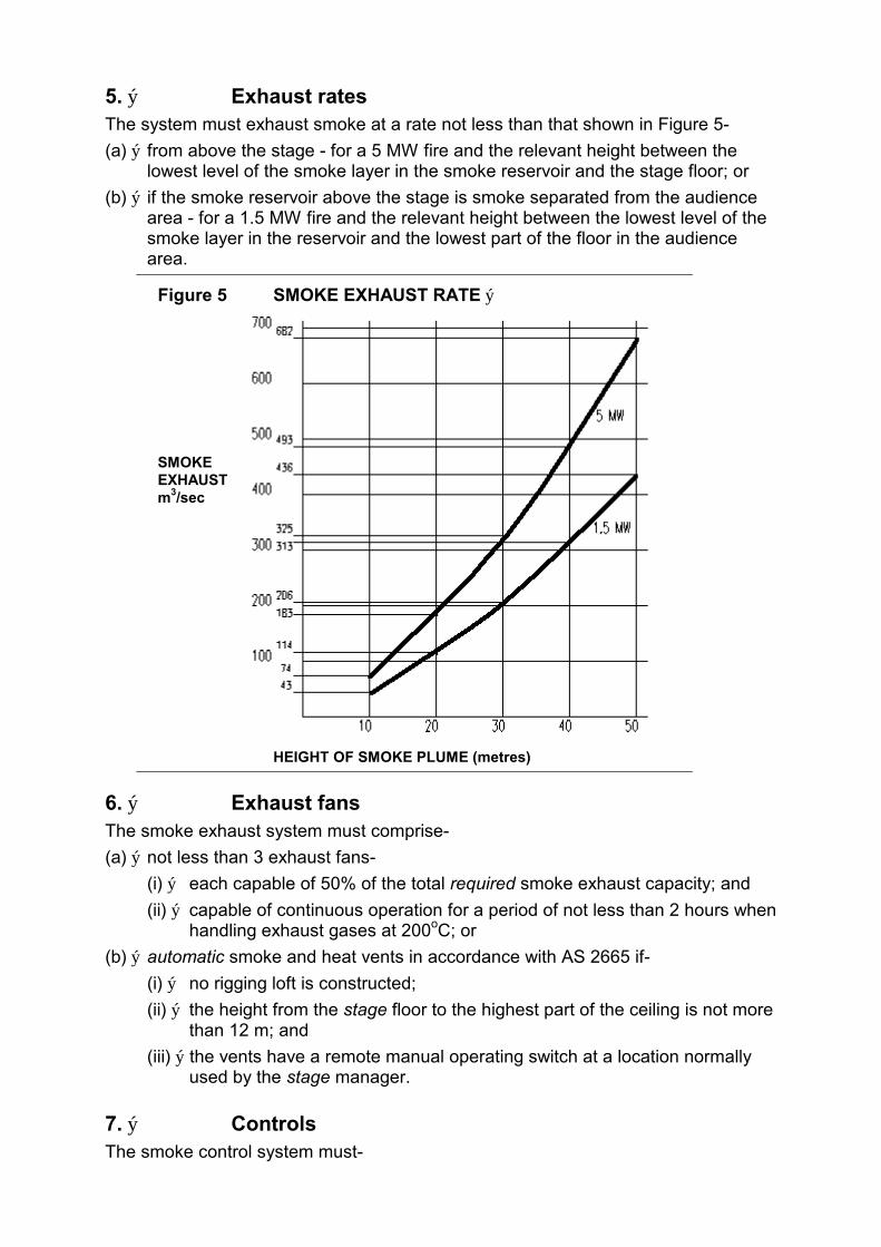
5. ý Exhaust rates The system must exhaust smoke at a rate not less than that shown in Figure 5-
(a) ý from above the stage - for a 5 MW fire and the relevant height between the lowest level of the smoke layer in the smoke reservoir and the stage floor; or
(b) ý if the smoke reservoir above the stage is smoke separated from the audience area - for a 1.5 MW fire and the relevant height between the lowest level of the smoke layer in the reservoir and the lowest part of the floor in the audience area.
Figure 5 SMOKE EXHAUST RATE ý
SMOKE EXHAUST m 3/sec
HEIGHT OF SMOKE PLUME (metres)
6. ý Exhaust fans The smoke exhaust system must comprise-
(a) ý not less than 3 exhaust fans-
(i) ý each capable of 50% of the total required smoke exhaust capacity; and
(ii) ý capable of continuous operation for a period of not less than 2 hours when handling exhaust gases at 200oC; or
(b) ý automatic smoke and heat vents in accordance with AS 2665 if-
(i) ý no rigging loft is constructed;
(ii) ý the height from the stage floor to the highest part of the ceiling is not more than 12 m; and
(iii) ý the vents have a remote manual operating switch at a location normally used by the stage manager.
7. ý Controls The smoke control system must-
(a) ý be actuated by the operation of-
(i) ý the sprinkler system;
(ii) ý an automatic fire alarm system or manual break-glass fire alarm where provided; and
(iii) ý a manual start switch at the location normally used by the stage manager and adjacent to an exit from the audience seating area; and
(b) ý for all valves controlling the sprinkler system heads over the stage area have clearly marked tamper switches connected to a monitoring panel at the location normally used by the stage manager.
8. ý Make-up air supply Make-up air must be available-
(a) ý at or near the lowest part of the audience seating area;
(b) ý at a low level around the perimeter of the audience seating areas; or
(c) ý from the normal air-conditioning system if it does not disturb the rising plume of smoke being exhausted or the smoke layer in the smoke reservoir.
SPECIFICATION H1.3 ý CONSTRUCTION OF THEATRES WITH PROSCENIUM WALLS
1. ý Scope This Specification contains the requirements for the construction of proscenium walls and mechanical ventilation for theatres, public halls, or the like.
2. ý Separation of stage areas, etc (a) ý Dressing rooms, scene docks, property rooms, workshops, associated store
rooms and other ancillary areas must be-
(i) ý located on the stage side of the proscenium wall; and
(ii) ý separated from corridors and the like by construction having an FRL of not less than 60/60/60, and if of lightweight construction, complying with Specification C1.8.
(b) ý The stage and backstage must be separated from other parts of the building other than the audience seating area by construction having an FRL of not less than 60/60/60, and if of lightweight construction, complying with Specification C1.8.
(c) ý Any doorway in the construction referred to in paragraphs (a) and (b) must be protected by a self-closing 60/60/30 fire door.
3. ý Proscenium wall construction A proscenium wall must-
(a) ý extend to the underside of the roof covering or the underside of the structural floor next above; and
(b) ý have an FRL of not less than 60/60/60, and if of lightweight construction, comply with Specification C1.8.

4. ý Combustible materials not to cross proscenium wall Timber purlins or other combustible material must not pass through or cross any proscenium wall.
5. ý Protection of openings in proscenium wall Every opening in a proscenium wall must be protected-
(a) ý at the principal opening, by a curtain in accordance with clause 6 which is-
(i) ý capable of closing the proscenium opening within 35 seconds either by gravity slide or motor assisted mechanisms;
(ii) ý operated by a system of automatic heat activated devices, manually operated devices or push button emergency devices; and
(iii) ý able to be operated from either the stage side or the audience side of the curtain; and
(b) ý at any doorway in the wall, by a self-closing 60/60/30 fire door.
6. ý Proscenium curtains A curtain required by Clause 5 must be-
(a) ý a fire safety curtain-
(i) ý made of non-combustible material;
(ii) ý capable of withstanding a pressure differential of 0.5 kPa over its entire surface area; and
(iii) ý so fitted that when fully lowered it inhibits the penetration of smoke around the perimeter of the opening, from the stage; or
(b) ý a curtain-
(i) ý having a Spread-of-Flame Index not greater than 0 and a Smoke-Developed Index not greater than 3; and
(ii) ý protected by a deluge system of open sprinklers installed along the full width of the curtain.
7. ý Mechanical ventilation Every stage must have a system of mechanical ventilation with sufficient capacity to exhaust an amount of air whichever is the greater of-
(a) ý 5 000 L/s; or
(b) ý the sum of-
(i) ý 10 L/s.m2 of the performing area of the stage;
(ii) ý 20 L/s.m2 of the remaining area of the stage; and
(iii) 20 L/s.m2 of the area of the rigging loft.
******************************************************************************************

WESTERN AUSTRALIA BOA APPENDIX
INTRODUCTION
This Appendix Contains variations and additions to the provisions of the BCA 1988 which are considered necessary for the continued effective application of that Code in Western Australia and shall be treated as amendments to that Code.
This Appendix supersedes the March 1989 Appendix. Where a variation or addition has been made to the BOA, the relevant clause number may be noted by means of Δflagging≈ in the column adjacent to the affected BOA clause.
Reference should then be made to the appropriate clause in this Appendix to determine any particular requirements for Western Australia.
This document is published by the Department of Local Government, 32 St. George«s Terrace, Perth WA 6000.
CONTENTS
A - GENERAL PROVISIONS WA A1.1 Definitions
WA Specification A1.3 Standards Adopted by Reference.
B - STRUCTURE WAB1.3(i) Footings
WA B1.3(o) Earth wall construction
WA B1.3(p) Seismic construction: Glass 1 buildings
WA Specification B1.3.1 Earth Wall Construction.
WA Specification B1.3.2 Seismic Construction- Class 1 Buildings.
C - FIRE RESISTANCE WA C2.3 Large isolated buildings
WA C2. 12 Separation of equipment
WA C3.3 Separation of openings in different fire compartments
WA Specification C1.1 Fire resisting construction
WA Specification C1.9 Fire resistance of Class 1 and 10 buildings
WA Specification C1.10 Early fire hazard indices
WA Specification C3.4 Fire doors, smoke doors, fire windows and shutters
D - ACCESS AND EGRESS WA D1.3 When fire-isolated exits are required
WA D1.4 Exit travel distances
WA D1.10 Discharge from exits
WA D2.1 Application of Part

WESTERN AUSTRALIA BOA APPENDIX
WA D2.7 Installations in exits and paths of travel ý
WA D2.13 Treads and risers ý
WA D2.16 Balustrades ý
WA D2.19 Doorways and doors ý
WA D3.2 Access for people with disabilities ý
WA D3.3 Parts of buildings to be accessible ý
WA D3.4 Concessions ý
E - SERVICES AND EQUIPMENT WA E1.2 Fire mains and water supply
WA E1.3 Fire hydrants
WA E1.4 Hose reels
WA E2.1 Smoke control
WA E2.2 Exclusion of smoke from fire-isolated exits
WA E2.3 Windows, panels or the like
WA E2.4 Air-handling systems
WA E2.5 Roof vents
WA E2.7 Pressurisation
WA E3.4 Emergency lifts
WA E4.2 Emergency lighting requirements
WA Specification E1.2 Fire mains and water supply services.
WA Specification E1.7 Fire detection and alarm systems
WA Specification E1.8 Fire Emergency Control Centres.
WA Specification E2.4 Mechanical Smoke Control in Multi-storey Buildings.
WA Specification E2. 6 Smoke Exhaust Systems.
F -HEALTH AND AMENITY WA F1.11 Provision of floor wastes ý
WA F2.4 Facilities for people with disabilities ý
WA F2.5 Construction of sanitary compartments ý
WA F4.4 Artificial lightin9 ý
WA F4.12 Reflective glazing ý
WA F5.1 Application of part ý
WA F5.3 Sound insulation of floors between units ý
G - ANCILLARY PROVISIONS WA Specification G3.8 Fire and Smoke Control Systems in Atrium Buildings.
WESTERN AUSTRALIA BOA APPENDIX
SECTION A GENERAL PROVISIONS
PART A1 INTERPRETATION
Insert the following heading for A1.1 Definitions:
WA A1.1 Definitions
Delete the definition of Professional engineer and insert the following:
Professional engineer means a person with appropriate experience in the relevant field, being-
(a) ý if legislation so requires a registered professional engineer in the relevant discipline; or
(b) ý otherwise - eligible to become a Corporate Member of the Institution of Engineers Australia.
Insert the following heading for Specification A1.3:
WA Specification A1.3 STANDARDS ADOPTED BY REFERENCE
In Specification A1.3 Table 1, insert the following after ISO 140:
WA TABLE 1 SCHEDULE OF REFERENCED DOCUMENTS No. Date Title BCA
Clause(s)
AS 1680 -1976 Code of practice for interior lighting and the visual environment
..
WA F4.4
BS 336 Fire hose couplings and ancillary equipment
..
WA E1.3
SECTION B STRUCTURE
PART B1 STRUCTURAL PROVISIONS
Insert the following heading for B1.3:
WA B1.3 Construction deemed-to-satisfy 1. ý Delete (i) in B1.3; and
2. ý Delete (o) in B1.3 and substitute the following:
(o) ý Earthwall construction: WA Specification B1.3.1.
(p) ý Seismic construction: Class 1 buildings: WA Specification B1.3.2.
WESTERN AUSTRALIA BOA APPENDIX
After Part B2, insert WA Specification B1.3.1 as follows:
WA SPECIFICATION B1.3.1 ý EARTH WALL CONSTRUCTION
1. Scope
This Specification contains the requirements for earth-wall construction.
2. Definitions
For the purpose of this Specification:
Adobe construction means a type of construction using blocks of sun dried mud.
Bulletin 5 means CSIRO-NBTC Bulletin 5 Earth Wall Construction Fourth Edition 1987.
Earth-wall construction means adobe construction, mechanically pressed-soil block construction or rammed-earth construction.
Mechanically pressed-soil block construction means a type of construction using blocks produced by pressed block making machines.
Rammed-earth construction means a type of construction in which damp earth is tamped in situ between temporary movable framework.
Terrain Category followed by a designation, refers to the terrain category so designated in AS 1170.2.
3. Not permitted in certain places
A building must not be of earth-wall construction if it is situated-
(a) ý on a site that is subject to flooding; or
(b) ý in a seismic zone 1 or 2 as defined by the Regulations unless it has been designed in accordance with A2.2.
4. Construction generally
(a) ý A building of earth-wall construction must be constructed in accordance with the recommendations contained in Bulletin 5 except where varied by this Specification.
(b) ý A building of earth-wall construction must not exceed two storeys in height and walls must be laterally restrained at intermediate floor level.
5. Sample of test results may be required
Prior to and during construction, Council may require-
(a) ý in the case of-
(i) ý rammed-earth construction a sample panel at least 900 mm long by 900 mm high;
(ii) ý adobe construction a sample comprising of a least 3 blocks,
made of the materials and by the methods to be used in the construction, to be provided for inspection on the site; and
(b) ý in the case of mechanically pressed-soil block construction the submission to it of the results of tests, conducted in accordance with Appendix E of Bulletin 5, made on blocks of the kind to be used in the construction after they have been moist cured for seven days.

WESTERN AUSTRALIA BOA APPENDIX
6. Minimum thickness of walls
In a building of earth-wall construction, the thickness of a wall must be-
(a) ý In the case of adobe construction or rammed-earth construction-
(i) ý for an external wall, not less than 250 mm; and
(ii) ý for an internal wall, not less than 200 mm;
(b) ý In the case of mechanically pressed-soil block construction-
(i) ý for an external wall, not less than 250 mm; and
(ii) ý for an internal wall, not less than 150 mm.
7. Protection
Every building of earth-wall construction-
(a) ý must be provided with a suitable means of protection to prevent water from the roof running down the face of every wall; and
(b) ý must, except in the case illustrated in Figure 1.3 of Bulletin 5, have the ground adjacent to the walls so graded and paved as to prevent any surface Water from reaching those walls.
After WA Specification B1.3.1, insert WA Specification B1.3.2 as follows:
WA Specification B1.3.2 ý SEISMIC CONSTRUCTION CLASS 1 BUILDINGS
1. Scope
This Specification contains the requirements for Class 1 buildings in seismic zones as defined by the Building Regulations.
2. Interpretation
In this Specification-
Timber framing connector means a manufactured connector system for timber joints formed from 1.2 mm galvanised steel and prepunched to take nails; and
Zone means a seismic zone as defined by the Building Regulations.
3. Construction in Zone A
In Zone A, every building exceeding 4 storeys in height must be designed by a professional engineer and comply with AS 2121.
4. Construction in Zone 1
In Zone 1, buildings and structural members must-
(a) ý be designed by a professional engineer to comply with AS 2121; or
(b) ý comply with Table 4, and
not incorporate any overhanging masonry ornamentations, parapets or unbraced masonry chimneys.
Table 4 ý SINGLE STOREY RESIDENTIAL BUILDINGS IN ZONE 1 WITHOUT CONCRETE TILE OR TERRACOTTA TILE ROOF-ALTERNATIVE DESIGN AND CONSTRUCTION
1. Foundations and Footings
WESTERN AUSTRALIA BOA APPENDIX ý
(a) ý Stumps supporting framed structures must be of steel, timber or reinforced concrete and stumps with an out of the ground length exceeding 650 mm must be braced.
(b) ý Floor beams must be fixed to the top of stumps with two 10 mm diameter bolts or the equivalent thereof.
(c) ý corner stumps must be braced in two directions and where a building dimension exceeds 10 m in length or width, intermediate bracing must be used at 10 m maximum centres.
(d) ý The bottom plates of framed structures must be fixed to a concrete raft or strip footing with M 10 bolts or masonry anchors at 1800 mm maximum centres.
(e) ý Concrete strip footings must be continuously reinforced with two layers of reinforcement comprising two 12 mm diameter bars ( Grade 4100 or 410Y) per layer and tied with R6 ligatures at centres not exceeding 2.5 times the depth of the footing.
(f) ý A raft incorporating a monolithic edge beam is deemed-to-satisfy (e).
2. Framed Wall Construction
(a) ý Where metal framing is used:
(i) ý The framing must conform with AS 1538 or AS 1664, and must be braced, nogged and fixed together using welding or the equivalent in strength using self tapping screws or bolts.
(ii) ý Wall plates must be continuous between cross walls or spliced so that no loss of strength occurs.
(iii) ý Material used in walls, other than bracing, must not be less than 1.2 mm In thickness.
(b) ý Where timber framing is used:
(i) ý The framing must be fixed together by the use of timber framing connectors nailed with a minimum of three 2.8 mm diameter x 30 mm long nails to each fixing plate of the connector or if of seasoned timber, may be alternatively fixed with two 2.8 mm diameter nails, machine nailed through the top or bottom plate into the stud.
(ii) ý Wall plates must be continuous between cross walls or spliced so that no loss of strength occurs.
3. Masonry Construction
Where masonry construction is used:
(a) ý Internal or external walls must not exceed 4 m in length unless stiffened by means of cross walls or by columns or bracing designed by a professional engineer.
(b) ý Cross walls must be tied to the internal leaf of cavity walls by fully bonding or by metal ties at every second course.
(c) ý Mortar must be at least as strong as a 1:1:6 mortar and the masonry units to have good mortar adherence properties and bricks must be laid on a full bed of mortar with cross joints properly filled.
(d) ý Both leaves of all external masonry walls must be reinforced with two R6 bars (Grade 230), or two 3.15 mm diameter bars (Grade 450), in the course immediately under window sills and over door and window heads.
(e) ý Reinforcement must extend a minimum of 300 mm beyond the supporting cross walls or columns and reinforcement to the external leaf must be galvanised.
(f) ý Continuous reinforced brick bond beams, comprising two R6 bars (Grade 230), or two 3.15 mm diameter bars (Grade 450), in each of the top three bed joints, must be constructed-
(i) ý in every case, on the internal leaf of all external walls and on all cross walls; and
(ii) ý where the roof is pitched on the external leaf of the external walls, on that external leaf.
(g) ý Cross wall reinforcement must be turned and lapped 300 mm into the external walls.
(h) ý Splices in reinforcement must not be less than 300 mm.
(i) ý The top two courses of all internal walls and of the internal leaf of all external walls must be constructed of bricks that contain no perforations.
4. Veneer on Framed Construction

WESTERN AUSTRALIA BOA APPENDIX
Where veneer on framed construction is used:
(a) ý Only veneers comprising an external skin of masonry and internal partitions of timber or metal framing may be used.
(b) ý The veneer must be fixed in accordance with AS 1640.
5. ý Roof Construction
(a) ý The roof structure must be braced so that all horizontal loads are transferred directly to the crosswalls.
(b) ý The roof framing must be fixed to the wall top plate by the use of timber framing connectors nailed with a minimum of three 2.8 mm diameter x 30 mm long nails to each fixing plate of the connector.
(c) ý Where the walls are of masonry construction all top plates must be connected to the walls by masonry anchors, or equivalent fixing, at a maximum of 1 800 mm centres, and every such fixing must be fixed into the second top course.
5. Construction in Zone 2
In Zone 2, buildings and structural members must-
(a) ý be designed by a professional engineer to comply with AS 2121; or
(b) ý comply with Table 5, and
not incorporate unreinforced masonry, overhanging ornamentations, parapets or unbraced masonry chimneys.
Table 5 ý SINGLE STOREY RESIDENTIAL BUILDINGS IN ZONE 2 WITHOUT CONCRETE TILE OR TERRACOTTA TILE ROOF AND NOT OF MASONRY CONSTRUCTION-ALTERNATIVE DESIGN AND CONSTRUCTION
1. Foundations and Footings
(a) ý Stumps supporting framed structures must be of steel, timber or reinforced concrete and stumps with an out of the ground length exceeding 500 mm must be braced.
(b) ý Floor beams must be fixed to the top of stumps with two M10 bolts or the equivalent thereof.
(c) ý Corner stumps must be braced in two directions and where a building dimension exceeds 8 m in length or width intermediate bracing must be provided at 8 m maximum centres.
(d) ý The bottom plate of framed structures must be fixed to a concrete raft or strip footing with M10 bolts or masonry anchors at 1200 mm maximum centres.
(e) ý Concrete strip footings must be continuously reinforced with two layers of reinforcement comprising two 12 mm diameter bars (Grade 4100 or 410Y) per layer and tied with R6 ligatures at centres not exceeding 2.5 times the depth of the footing.
(f) ý A raft incorporating a monolithic edge beam is deemed-to-satisfy (e).
2. Framed Wall construction
(a) ý Where metal framing is used:
(i) ý The framing must conform to ASlS38 or A51664, and must be braced, nogged and fixed together using welding or the equivalent in strength using self tapping screws or bolts.
(ii) ý Wall plates must be continuous between cross wails or spliced so that no loss of strength occurs.
(iii) ý Material used in walls other than bracing must not be less than 1.2 mm in thickness.
(b) ý Where timber framing is used:
(i) ý The framing must be fixed together by the use of timber framing connectors nailed with a minimum of three 2.8 mm diameter x 30 mm long nails to each fixing plate of the connector or if of seasoned timber, may be alternatively fixed with two 2.8 mm diameter nails, machine nailed through the top or bottom plate into the stud.

WESTERN AUSTRALIA BOA APPENDIX ý
(ii) ý Wall plates must be continuous between cross walls or spliced so that no loss of strength occurs.
3. Veneer on Framed Construction
(a) ý Where veneer on framed construction is used
(i) ý Only veneers comprising an external skin of masonry and internal partitions of timber or metal framing may be used.
(ii) ý The veneer must be fixed in accordance with AS 1640.
(iii) ý The top plate to the external frame must be continuous between internal cross walls supporting the external frame against lateral loads.
(b) ý Where timber framing is used
(i) ý Top plates must be of F8 grade timber not less in size than 75 mm x 50 mm and must be continuous between internal cross wails.
(ii) ý Supporting internal cross walls must be spaced not more than 4 m apart, except that where top plates of F8 grade timber not less in size than 100 mm x 50 mm are used cross walls may be spaced at a maximum of 4.8m.
(iii) ý The external walls must be fixed to supporting internal cross walls at or near top plate level, by at least two framing anchors with not less than three 2.8mm diameter nails to each tab of the framing anchor, or by bolting the frames together using a bolt of a size not less than M1O or the equivalent thereof.
(c) ý Where metal framing is used
(i) ý Top plates must be continuous between supporting internal cross walls, and for spans not exceeding 5.5 m between supporting cross walls the top plate must not be less in size than 78mm x 31 mm x 1.2mm or such other size as is approved, and, where the span exceeds 3.5 m, must be reinforced by a stiffened top plate not less in size than 75 mm x 79 mm x 1.6 mm or such other size as is approved;
(ii) ý The external walls must be fixed to the internal supporting walls at or near top plate level, by at least two framing anchors or by bolting using a bolt of a size not less than M1O or the equivalent thereof.
(d) ý A 100 mm x 100 mm galvanised steel mesh secured to the outside of the timber or steel frame must be used on all external walls to which masonry veneer is attached;
(e) ý Masonry veneer must not to be constructed over any openings or in any gable.
4. Roof construction
(a) ý The roof structure must be braced so that all horizontal loads are transferred directly to the cross walls.
(b) ý The roof framing must be fixed to the wall top plate by the use of timber framing connectors nailed with a minimum of three 2.8 mm diameter x 30 mm long nails to each fixing plate of the connector.
6. Free standing masonry walls
Free standing masonry walls exceeding 1.2 m in height must not be constructed in Zone 1 or Zone 2 unless designed by a professional engineer to resist seismic loads.
SECTION C FIRE RESISTANCE
PART C2 COMPARTMENTATION AND SEPARATION
Delete C2.3 and insert WA C2.3 as follows:
WA C2.3 Large isolated buildings The size of a fire compartment in a building may exceed that specified in Table C2.2 where-

WESTERN AUSTRALIA BOA APPENDIX
(a) ý the building does not exceed 18000 m2 in floor area or exceed 108 000 m3 in volume, if
(i) ý the building is Class 7 or 8, it contains not more than 2 storeys and an open space complying with C2.4(a) not less than 18 m wide is provided around the building; or
(ii) ý the building is of any Class and is protected throughout with a sprinkler system and perimeter vehicular access complying with C2.4(b) is provided; or
(b) ý the building exceeds 18000 m2 in floor area or 108 000 m3 in volume if-
(i) ý the building is protected throughout with a sprinkler system and perimeter vehicular access complying with C2.4(b) is provided; and
(ii) ý the ceiling height of the fire compartment is not more than 12 m, it has a smoke exhaust system in accordance with Specification E2.6 or smoke-and-heat vents and the space below the roof is divided into compartments in accordance with E2.5; or
(iii) ý the ceiling height is more than 12 m, it has a smoke exhaust system in accordance with Specification E2.6; and
(c) ý there is more than one building on the allotment-
(i) ý each building must comply with (a) or (b); or
(ii) ý if the buildings are closer than 6 m to each other they are regarded as one building and collectively must comply with (a) or (b).
Delete C2.12 and substitute the following:
WA C2.12 Separation of Equipment (a) ý Equipment other than that described in (b) must be isolated by walls and floors
having an FRL of not less than 120/1 20/1 20 if that equipment comprises-
(i) ý lift motors and lift control panels;
(ii) ý the main electrical switchboard in a building and it serves emergency equipment;
(iii) ý required stair pressurising equipment;
(iv) ý emergency generators or central smoke control plant;
(v) ý boilers;
(vi) ý batteries; or
(vii) ýsprinkler valve equipment.
(b) ý Equipment need not comply with (a) if it is-
(i) located in a separate storey (or in the topmost storey) that is separated from the remainder of the building by floor construction having an FRL of 120/120/120;
(ii) ý smoke control exhaust fans located in the air stream and they are constructed for high temperature operation in accordance with Specification E2.6; or
(iii) ý equipment otherwise adequately separated from the remainder of the building.
(c) ý Separation of on-site fire pumps must comply with clause 3(b) of Specification E1.2.

WESTERN AUSTRALIA BOA APPENDIX
PART C3 PROTECTION OF OPENINGS
Delete C3.3 and insert WA C3.3 as follows:
WA C3.3 Separation of openings in different fire compartments Unless they are protected in accordance with C3.4, the distance between openings in external walls in compartments separated by a fire wall must not be less than that set out in Table C3.3.
Table C3.3 DISTANCE BETWEEN OPENINGS IN DIFFERENT FIRE COMPARTMENTS
ANGLE BETWEEN WALLS ý MIN. DISTANCE BETWEEN OPENINGS
0o (walls opposite) 6 m
more than 0o to 45o 5 m
more than 45o to 90o 4 m
more than 90o to 135o 3 m
more than 135o to less than 180o 2 m
Insert the following heading for Specification C1.1
WA Specification C1.1 FIRE-RESISTING CONSTRUCTION
Delete (a) in clause 2.5 and substitute the following:
(a) ý Steel columns- Except in a fire wall, common wall or as an external column, a steel column need not have an FRL in a building that contains only one storey.
Insert the following heading for Specification C1.9
WA Specification C1.9 FIRE-RESISTANCE OF CLASS 1 AND 10 BUILDINGS
6. Exceptions
Delete (b).
Insert the following heading for Specification C1.10
WA Specification C1.1O EARLY FIRE HAZARD INDICES
Delete clause 4 and insert WA clause 4 as follows:
4. Class 2, 3 and 9 buildings
A material other than a sarking-type material must, if-
(a) ý in a Class 2, 3, 9a or 9b building, it is used as a finish, surface, lining or attachment to any wall or ceiling in a public corridor which is a means of egress to-
(i) ý a required fire-isolated stairway or an external stairway used instead; or
(ii) ý a required fire-isolated passageway, or required fire-isolated ramp, have a Spread-of-Flame Index of 0 and a Smoke-Developed Index of not more than 5; or
WESTERN AUSTRALIA BOA APPENDIX
(b) ý in a Class 9b building in a patient-care area, it is used as a finish, surface, lining or attachment to a-
(i) ý ceiling - have a Spread-of-Flame Index of 0 and a Smoke-Developed Index of not more than 3; and
(ii) ý wall - have a Spread-of-Flame Index of not more than 2 and a Smoke-Developed Index of not more than 5; and
(iii) ý floor - have a Spread-of-Flame Index of not more than 3 and a Smoke-Developed Index of not more than 5, or a Spread-of-Flame Index of 0 and a Smoke-Developed Index of not more than 6; or
(c) ý in a Class 9 building used as a theatre, public hall or the like, in the auditorium or audience seating area and associated assembly areas, it is used as a finish, surface, lining or attachment to a-
(i) ý ceiling - have a Spread-of-Flame Index of not more than 6 and a Smoke-Developed Index of not more than 3; and
(ii) ý wall - have a Spread-of-Flame Index of not more than 6 and a Smoke-Developed Index of not more than 5; and
(iii) ý floor - have a Spread-of-Flame lndex of not more than 7 and a Smoke-Developed Index of not more than 5; or
(d) ý in a Class 9 building used as a theatre, public hall or the like, it is used in any part of fixed seating in the audience area or auditorium -have a Spread-of-Flame Index of 0 and a Smoke-Developed Index of not more than 5.
Insert the following heading for Specification C3.4
WA Specification C3.4 ý FIRE DOORS, SMOKE DOORS, FIRE WINDOWS AND SHUTFERS
Insert the following:
6. Signs
A sign must be installed where it can readily be seen on/or adjacent to each fire door and each smoke door stating-
ƒFIRE SAFETY DOOR ý DO NOT OBSTRUCT ý DO NOT WEDGE OPEN≈, ý
in capital letters not less than 50 mm high in a colour contrasting with the background.

WESTERN AUSTRALIA BOA APPENDIX
SECTION D ACCESS AND EGRESS
PART D1 PROVISION FOR ESCAPE
Insert the following heading for D1.3:
WA D1.3 When fire-isolated exits are required
Insert in D1.3 after (b) the following:
(c) ý Within buildings to which Part D3 applies, every required fire-isolated stairway must be provided at each floor level with a recess not less than 800 mm wide, 1200 mm deep and 2000 mm high.
Insert the following heading for D1.4:
WA D1.4 Exit travel distances Delete (c)(ii) in D1.4.
Insert the following heading for D1.10
WA D1.1O Discharge from exits
Delete (c) in D1.10 and insert the following:
(c) ý if an exit discharges to an open space that is at a different level than the public road to which it is connected, the path of travel to the road must be by-
(i) a ramp or other incline having a grade of not more than 1:8 at any part, or 1:12 if required by Part D3; or
(ii) ý except if the exit is from a Class 9a building, a stairway complying with this Code.
PART D2 CONSTRUCTION OF EXITS
Delete D2.1 and substitute the following:
WA D2.1 Application of Part Except for WA D2.16(h), this Part does not apply to-
(a) ý a Class 1 or Class 10 building; or
(b) ý the internal parts of a sole-occupancy unit in a Class 2 or Class 3 building or a Class 4 part of a building.
Insert the following heading for D2.7:
WA D2.7 Installations in exits and paths of travel
Delete (d) and substitute the following:
(d) ý Services or equipment must not be installed in a required exit that is not fire-isolated or in any corridor, hallway, lobby or the like leading to a required exit if it comprises-
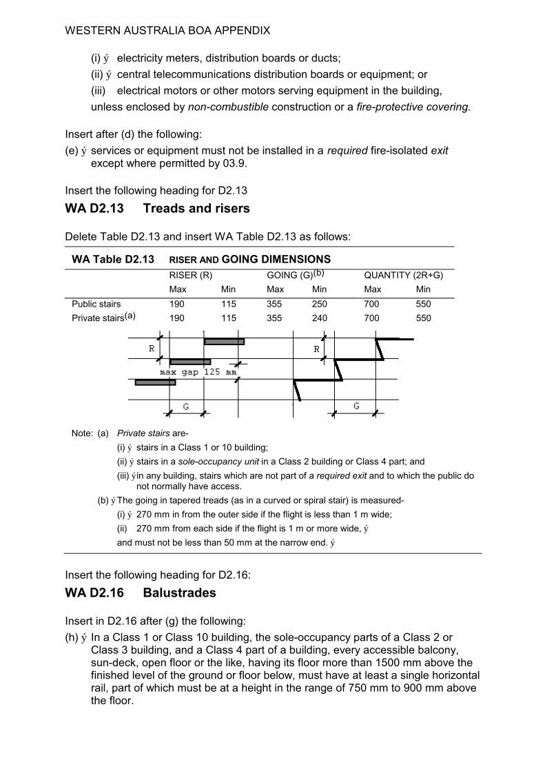
WESTERN AUSTRALIA BOA APPENDIX
(i) ý electricity meters, distribution boards or ducts;
(ii) ý central telecommunications distribution boards or equipment; or
(iii) electrical motors or other motors serving equipment in the building,
unless enclosed by non-combustible construction or a fire-protective covering.
Insert after (d) the following:
(e) ý services or equipment must not be installed in a required fire-isolated exit except where permitted by 03.9.
Insert the following heading for D2.13
WA D2.13 Treads and risers
Delete Table D2.13 and insert WA Table D2.13 as follows:
WA Table D2.13 RISER AND GOING DIMENSIONS RISER (R) GOING (G)(b) QUANTITY (2R+G)
Max Min Max Min Max Min
Public stairs 190 115 355 250 700 550
Private stairs(a) 190 115 355 240 700 550
Note: (a) Private stairs are-
(i) ý stairs in a Class 1 or 10 building;
(ii) ý stairs in a sole-occupancy unit in a Class 2 building or Class 4 part; and
(iii) ýin any building, stairs which are not part of a required exit and to which the public do not normally have access.
(b) ý The going in tapered treads (as in a curved or spiral stair) is measured-
(i) ý 270 mm in from the outer side if the flight is less than 1 m wide;
(ii) 270 mm from each side if the flight is 1 m or more wide, ý
and must not be less than 50 mm at the narrow end. ý
Insert the following heading for D2.16:
WA D2.16 Balustrades
Insert in D2.16 after (g) the following:
(h) ý In a Class 1 or Class 10 building, the sole-occupancy parts of a Class 2 or Class 3 building, and a Class 4 part of a building, every accessible balcony, sun-deck, open floor or the like, having its floor more than 1500 mm above the finished level of the ground or floor below, must have at least a single horizontal rail, part of which must be at a height in the range of 750 mm to 900 mm above the floor.

WESTERN AUSTRALIA BOA APPENDIX
Insert the following heading for D2.19:
WA D2.19 Doorways and doors
Delete (c) in D2.19 and substitute the following:
(c) ý must not be fitted with a sliding door unless-
(i) ý it serves a building or part with a floor area not more than 200 m2
(ii) ý the door may be opened manually under a force of 110 N;
PART D3 ACCESS FOR PEOPLE WITH DISABILITIES
Delete D3.2 and substitute the following:
WA D3.2 Access to buildings Access for people with disabilities must be provided as set out in WA Table D3.2 and in accordance with AS 1428.1, except that the rise between landings of a walkway or ramp must not exceed 750 mm and the gradient must not be steeper than 1:12, and such access must provide a continuous path of travel-
(a) ý from a road boundary of the allotment;
(b) ý from any carpark space on the allotment (whether within or outside the building)-
(i) ý that is set aside for people with disabilities using the building; or
(ii) ý if there are no carpark spaces set aside for them, from any carpark area that serves the building; and
(c) ý from any other building on the allotment to which access for people with disabilities is required.
WA TABLE D3.2 REQUIREMENTS FOR ACCESS FOR PEOPLE WITH DISABILITIES BUILDING ACCESS REQUIREMENTS
Class 3
(a) ý If the building contains- To and within-
more than 10 sole-occupancy units up to one sole-occupancy unit ý 49 units ý
more than 49 units but not more than 99 2 sole-occupancy units ý
more than 99 units 3 sole-occupancy units ý
(b) ý accommodation for more than 10 persons other than in sole- occupancy units
up to 49 beds 2 beds ý
more than 49 beds but not more than 99 4 beds ý
more than 99 beds 6 beds ý
(c) ý Common areas that are required to be the entrance floor and to all public areas on every accessible floor.
Note: For the purposes of this Table, a double bed counts as one bed.
Class 5, 6, 7 and 8 ý To and within buildings in which more than 100 persons are accommodated, determined in accordance with D1.13; and
To and within any floor to which vertical access by way of a ramp, step ramp or kerb ramp, or
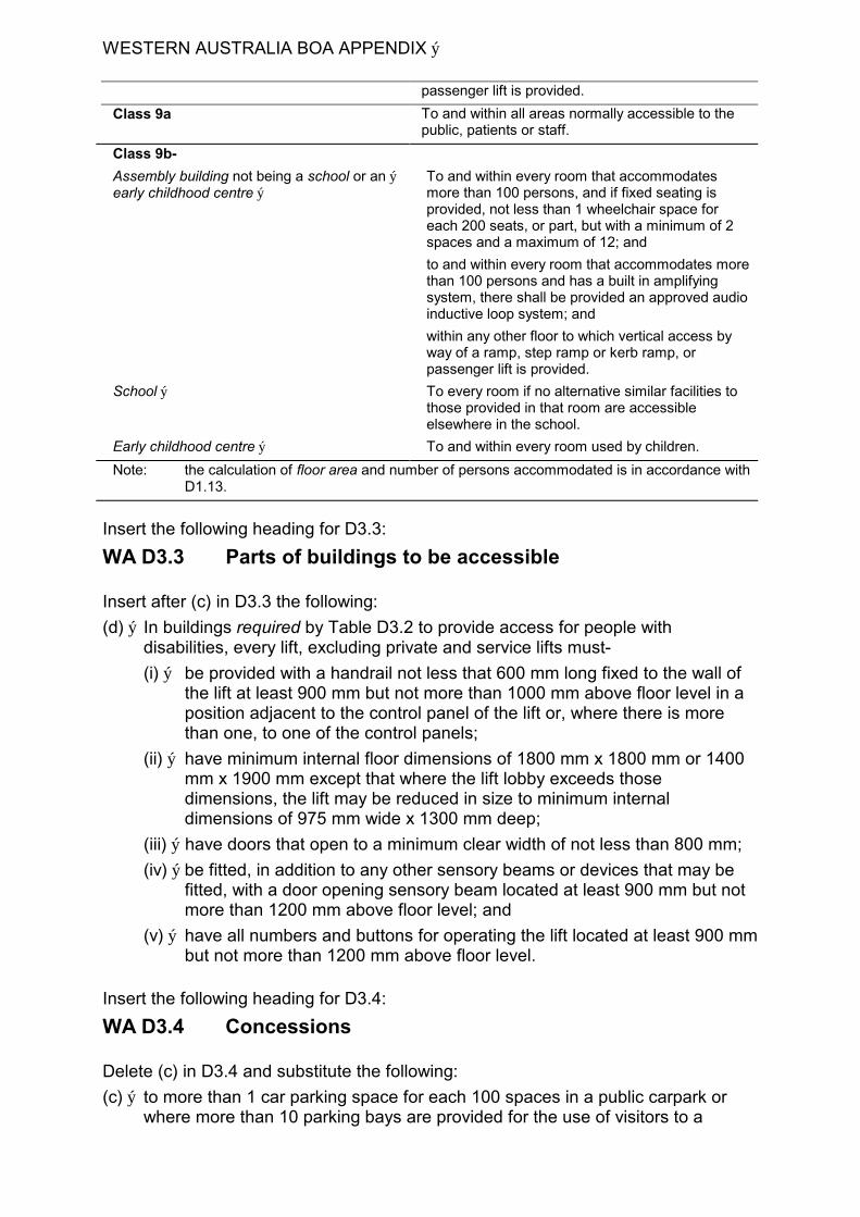
WESTERN AUSTRALIA BOA APPENDIX ý
passenger lift is provided.
Class 9a To and within all areas normally accessible to the public, patients or staff.
Class 9b-
Assembly building not being a school or an ý To and within every room that accommodates early childhood centre ý more than 100 persons, and if fixed seating is
provided, not less than 1 wheelchair space for each 200 seats, or part, but with a minimum of 2 spaces and a maximum of 12; and
to and within every room that accommodates more than 100 persons and has a built in amplifying system, there shall be provided an approved audio inductive loop system; and
within any other floor to which vertical access by way of a ramp, step ramp or kerb ramp, or passenger lift is provided.
School ý To every room if no alternative similar facilities to those provided in that room are accessible elsewhere in the school.
Early childhood centre ý To and within every room used by children.
Note: the calculation of floor area and number of persons accommodated is in accordance with D1.13.
Insert the following heading for D3.3:
WA D3.3 Parts of buildings to be accessible
Insert after (c) in D3.3 the following:
(d) ý In buildings required by Table D3.2 to provide access for people with disabilities, every lift, excluding private and service lifts must-
(i) ý be provided with a handrail not less that 600 mm long fixed to the wall of the lift at least 900 mm but not more than 1000 mm above floor level in a position adjacent to the control panel of the lift or, where there is more than one, to one of the control panels;
(ii) ý have minimum internal floor dimensions of 1800 mm x 1800 mm or 1400 mm x 1900 mm except that where the lift lobby exceeds those dimensions, the lift may be reduced in size to minimum internal dimensions of 975 mm wide x 1300 mm deep;
(iii) ý have doors that open to a minimum clear width of not less than 800 mm;
(iv) ý be fitted, in addition to any other sensory beams or devices that may be fitted, with a door opening sensory beam located at least 900 mm but not more than 1200 mm above floor level; and
(v) ý have all numbers and buttons for operating the lift located at least 900 mm but not more than 1200 mm above floor level.
Insert the following heading for D3.4:
WA D3.4 Concessions
Delete (c) in D3.4 and substitute the following:
(c) ý to more than 1 car parking space for each 100 spaces in a public carpark or where more than 10 parking bays are provided for the use of visitors to a
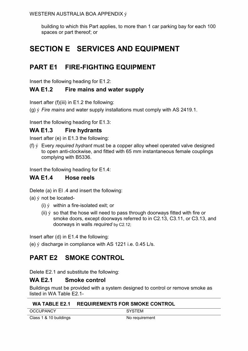
WESTERN AUSTRALIA BOA APPENDIX ý
building to which this Part applies, to more than 1 car parking bay for each 100 spaces or part thereof; or
SECTION E SERVICES AND EQUIPMENT
PART E1 FIRE-FIGHTING EQUIPMENT
Insert the following heading for E1.2:
WA E1.2 Fire mains and water supply
Insert after (f)(iii) in E1.2 the following:
(g) ý Fire mains and water supply installations must comply with AS 2419.1.
Insert the following heading for E1.3:
WA E1.3 Fire hydrants Insert after (e) in E1.3 the following:
(f) ý Every required hydrant must be a copper alloy wheel operated valve designed to open anti-clockwise, and fitted with 65 mm instantaneous female couplings complying with B5336.
Insert the following heading for E1.4:
WA E1.4 Hose reels
Delete (a) in El .4 and insert the following:
(a) ý not be located-
(i) ý within a fire-isolated exit; or
(ii) ý so that the hose will need to pass through doorways fitted with fire or smoke doors, except doorways referred to in C2.13, C3.11, or C3.13, and doorways in walls required by C2.12;
Insert after (d) in E1.4 the following:
(e) ý discharge in compliance with AS 1221 i.e. 0.45 L/s.
PART E2 SMOKE CONTROL
Delete E2.1 and substitute the following:
WA E2.1 Smoke control Buildings must be provided with a system designed to control or remove smoke as listed in WA Table E2.1-
WA TABLE E2.1 REQUIREMENTS FOR SMOKE CONTROL OCCUPANCY SYSTEM
Class 1 & 10 buildings No requirement
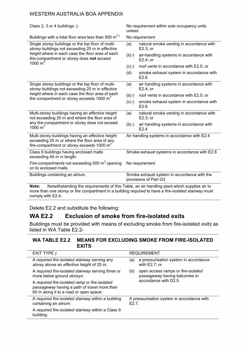
WESTERN AUSTRALIA BOA APPENDIX
Class 2, 3 or 4 buildings: ý No requirement within sole occupancy units unless
Buildings with a total floor area less than 500 m2 ý No requirement
Single storey buildings or the top floor of multi- (a) natural smoke venting in accordance with storey buildings not exceeding 25 m in effective E2.3; or height where in each case the floor area of each (b) ý air-handling systems in accordance with fire-compartment or storey does not exceed E2.4; or 1000 m2
(c) ý roof vents in accordance with E2.5; or
(d) smoke exhaust system in accordance with E2.6
Single storey buildings or the top floor of multi- (a) air handling systems in accordance with storey buildings not exceeding 25 m in effective E2.4; or height where in each case the floor area of each (b) ý roof vents in accordance with E2.5; or fire compartment or storey exceeds 1000 m2
(c) ý smoke exhaust system in accordance with E2.6
Multi-storey buildings having an effective height (a) natural smoke venting in accordance with not exceeding 25 m and where the floor area of E2.3; or any fire-compartment or storey does not exceed (b) ý air handling systems in accordance with 1000 m2
E2.4
Multi-storey buildings having an effective height Air handling systems in accordance with E2.4 exceeding 25 m or where the floor area of any fire-compartment or storey exceeds 1000 m2
Class 6 buildings having enclosed malls Smoke exhaust systems in accordance with E2.6 exceeding 40 m in length:
Fire-compartments not exceeding 500 m2 opening No requirement on to enclosed malls.
Buildings containing an atrium. Smoke exhaust system in accordance with the provisions of Part G3
Note: Notwithstanding the requirements of this Table, an air handling plant which supplies air to more than one storey or fire compartment in a building required to have a fire-isolated stairway must comply with E2.4.
Delete E2.2 and substitute the following:
WA E2.2 Exclusion of smoke from fire-isolated exits Buildings must be provided with means of excluding smoke from fire-isolated exits as listed in WA Table E2.2-
WA TABLE E2.2 MEANS FOR EXCLUDING SMOKE FROM FIRE-ISOLATED EXITS
EXIT TYPE ý REQUIREMENT
A required fire-isolated stairway serving any (a) a pressurisation system in accordance storey above an effective height of 25 m: with E2.7; or
A required fire-isolated stairway serving three or (b) open access ramps or fire-isolated more below ground storeys: passageway having balconies in
accordance with D2.5. A required fire-isolated ramp or fire-isolated passageway having a path of travel more than 60 m along it to a road or open space:
A required fire-isolated stairway within a building A pressurisation system in accordance with containing an atrium: E2.7.
A required fire-isolated stairway within a Class 9 building:

WESTERN AUSTRALIA BOA APPENDIX
Note: A below ground storey is one which is partially or wholly below ground and is not counted in the rise in storeys in accordance with C1.2.
Delete E2.3 and substitute the following:
WA E2.3 Natural smoke venting Windows, doors, panels or the like, provided to control the movement of smoke must-
(a) be in accordance with Part F4; and
(b) be as evenly distributed as practicable; and
(c) be readily openable, except that where windows, panels or the like are provided on the ground level storey they need only be shatterable.
Delete E2.4 and substitute the following:
WA E2.4 Air handling systems Where an air handling system is installed in a building it must-
(a) ý if it supplies air to more than one storey or fire compartment operate in accordance with-
(i) ý AS 1668.1 where the building does not exceed 25 m in effective height; or
(ii) ý Specification E2.4 where the building exceeds 25 m in effective height; or
(b) ý if it supplies air to a single storey or fire-compartment, operate in accordance with Specification E2.4.
Delete E2.5 and substitute the following:
WA E2.5 Roof vents Required roof vents must comply with the performance requirements of AS 2427 and be installed as part of a complete smoke/heat venting system complying with AS 2665, except that-
(a) ý permanently open vents may form part of the required fire venting system provided that the required aerodynamic area of the total venting system complies with AS 2665 and the vents comply with all other construction and performance requirements of AS 2427;
(b) ý all automatic roof vents within the same roof smoke compartment must open at the same time; and
(c) ý roof vents must be activated by-
(i) ý in a Class 7 or 8 building -any fusible link within a roof smoke compartment; or
(ii) ý a sprinkler system if it is installed throughout the building; or
(iii) ý a fire detection and alarm system which complies with AS 1670; and
(iv) ý smoke detectors spaced not more than 30 m apart and 15 m from any curtain and with not less than one detector for each 500 m2 of floor area; or
(v) ý rate of rise heat detectors spaced not more than 15 m apart and 7.5 m from any curtain and with not less than one detector for each 250 m2 of floor area.

WESTERN AUSTRALIA BOA APPENDIX
Delete E2.7 and substitute the following:.
WA E2.7 ý Pressurisation A required system designed to exclude smoke from a fire-isolated exit, together with any smoke lobby provided under D1.7, must-
(a) ý comply with AS 1668.1, except that-
(i) ý the criteria of 50 Pa pressure differential across each door when all doors are closed does not apply; and
(ii) ý in a smoke control system complying with Specification E2.4, the air velocity at the door does not apply to non-fire floors, and openable windows or other openable devices (other than necessary doorways, pressure-controlled relief louvres and windows openable by a key) must not be in the stairway, ramp or passageway; and
(b) ý not serve more than one fire-isolated exit system and not form part of any other air handling system;
(c) ý be activated by-
(i) ý a smoke detector located not more than 1.5 m horizontal distance from each doorway affording access to the fire-isolated stairway, fire-isolated ramp or fire-isolated passageway; and
(ii) ý any other required fire detection system that is installed in the building.
PART E3 ý LIFT INSTALLATIONS
Insert the following heading for E3.4:
WA E3.4 ý Emergency lifts
Delete (b)(i) and substitute the following:
(b) ý (i) Provide for Fire Service Control in accordance with AS 1735.2 except that the protection from door edge reopening devices must be retained.
PART E4 ý EMERGENCY LIGHTING, EXIT SIGNS AND WARNING SYSTEMS
Delete E4.2 and substitute the following:
WA E 4.2 ý Emergency lighting requirements An emergency lighting system must be installed-
(a) ý in every fire-isolated stairway, fire-isolated ramp or fire-isolated passageway;
(b) ý in every storey of a Class 5, 6, 7, 8 or 9 building where the storey has a floor area of more than 300 m2-
(i) ý in every passageway, corridor, hallway, or the like, that is part of a path of travel to an exit;
(ii) ý in any room having a floor area more than 100 m2 that does not open to a corridor or space that has emergency lighting or to a road or open space;
(iii) ý in any room having a floor area of more than 300 m2
WESTERN AUSTRALIA BOA APPENDIX ý
(c) ý in every passageway, corridor, hallway, or the like, having a length of more than 6 in from the entrance doorway of any sole-occupancy unit in a Class 2 or 3 building or Class 4 part to the nearest doorway opening directly to
(i) ý a fire-isolated stairway, fire-isolated ramp or fire-isolated passageway;
(ii) ý an external stairway serving instead of a fire-isolated stairway under D1.8; or
(iii) ý an external balcony leading to a fire-isolated stairway, fire-isolated ramp or fire-isolated passageway; or
(iv) ý a road or open space;
(d) ý in every required non-fire-isolated stairway;
(e) ý in a sole-occupancy unit in a Class 5, 6 or 9 building if-
(i) ý the floor area of the unit is more than 300 in2;and
(ii) ý an exit from the unit does not open to a road or open space or to an external stairway, passageway, balcony or ramp, leading directly to a road or open space;
(f) ý in every room or space to which there is public access in every storey in a Class 6 or 9b building if-
(i) ý the floor area in that storey is more than 300 in2
(ii) ý any point on the floor of that storey is more than 20 in from the nearest doorway opening directly to a stairway, ramp, passageway, road or open space;
(iii) ý egress from that storey involves a vertical rise within the building of more than 1.5 m, or any vertical rise if the storey concerned does not admit sufficient light; or
(iv) ý the storey provides a path of travel from any other storey required by (i), (ii), or (iii) to have emergency lighting;
(g) ý in a Class 9a building-
(i) ý in every passageway, corridor, hallway, or the like, serving a ward area or patient treatment room; and
(ii) ý in patient care areas having a floor area of more than 120 m2 and
(h) ý in every required fire control centre.
Insert the following heading for Specification E1.2:
WA Specification E1.2 ý FIRE MAINS AND WATER SUPPLY SERVICES
2. General requirements
Delete (b) and substitute the following:
(b) ý not to incorporate plastic pipes except where permitted by AS 2419.1; and
Insert in Specification E1.2, after clause 4, the following:
5. Ancillary equipment
(a) ý A fire main on which a hydrant is installed must have a minimum diameter of-
(i) ý 100 mm where one hydrant is connected; or

WESTERN AUSTRALIA BOA APPENDIX
(ii) ý 150 mm where two hydrants per storey are connected and the building has an effective height of more than 25 m; or
(iii) ý 150 mm where the effective height of the building is more than 60 m.
(b) ýSuitable pressure reducing devices must be installed when maximum permissible static pressure is exceeded.
(c) ý Control valves must be fitted to the main if the building has an effective height of more than 25 m, where-
(i) ý if a single main is provided control valves must be installed at intervals not exceeding 5 storeys; and
(ii) ý if two or more mains are provided they must be interconnected and fitted with control valves to enable isolation of parts of those mains.
(d) ý Where the height of a fire service exceeds 75 in it must be segregated into zones and a relay booster pump installed on the main between zones, and no zone must exceed 75 in height.
(e) ý A 100 mm diameter fire main must be fitted with two inlets, and a 150 mm main with four inlets, each consisting of a 60 mm instantaneous male coupling conforming with BS 336. Each inlet must be protected by a single twist release lugged blank cap to permit the release of any pressure build up behind the cap.
(f) ý Fire pumps serving hydrants shall be automatically started and stopped by pressure switches and manual override start and stop buttons located adjacent to the pumpset, at the Fire Brigade Booster connection within the cabinet and at the Fire Control Centre where provided. Manual fire pump control shall be clearly identified and labeled as appropriate-
Main Fire Pump - Start; Stop Circuit Booster Pump - Start; Stop Relay Circuit Booster Pump - Start; Stop
Insert the following heading for Specification E1.7
WA Specification E1.7 FIRE DETECTION AND ALARM SYSTEMS
6. Location of smoke detectors
Delete (c) and substitute the following:
(c) ý situated not more than 1.5 in horizontal distance from smoke doors or fire doors; and
Insert the following heading for Specification El .8:
WA Specification E1.8 FIRE EMERGENCY CONTROL CENTRES
7. Size and contents
Insert in 7(a), after (v), the following:
(vi) ý colour-coded, durable, tactical fire plans.
WESTERN AUSTRALIA BOA APPENDIX
Delete Specification E2.4 and substitute the following:
WA Specification E2.4 MECHANICAL SMOKE CONTROL
1. Scope
This Specification describes the performance and operation of air-handling systems used to control smoke.
2. Central air-conditioning plant
The installed central air-conditioning system may be utilized for smoke control if it complies with AS 1668.1, and-
(a) ý additional smoke control dampers are introduced into the smoke exhaust and supply air ductwork at each storey or fire-compartment-
(i) ý to stop the supply air to the fire affected storey or fire-compartment and continue to supply air to all other storeys and fire-compartments; and
(ii) ý to exhaust the smoke from the fire affected storey or fire-compartment; and
(iii) ý to achieve not less than 20 Pa positive pressure in all other storeys and fire-compartments, above the pressure in the fire affected storey or fire-compartment; and
(iv) ý to fail safe to a condition of all supply air and exhaust smoke dampers fully open; and
(v) ý in such a manner that the fire integrity of the building is not compromised; and
(b) ý sufficient air from other storeys or fire-compartments must be mixed with the smoke exhaust from the fire affected storey or fire-compartment to reduce the temperature of the exhaust gasses at the exhaust fan to a minimum of 2000C.
3. Individual air-conditioning units on each floor
Where an air-handling system supplies air to a single storey or fire-compartment-
(a) ý the air-handling unit in the fire-affected storey or fire-compartment must stop; and
(b) ý the air-handling units in all other storeys or fire-compartments must supply full fresh air to those storeys or fire-compartments; and
(c) ý the fire-affected storey or fire-compartment must be relieved to outside or exhausted, to achieve not less than 20 Pa positive pressure in all other storeys and fire-compartments, above the pressure in the fire affected storey or fire-compartment.
4. Actuation of smoke control system
The smoke control system must be automatic in operation and actuated by-
(a) ý smoke detectors located adjacent to each required exit and return air path in each storey in accordance with Specification El .7; and
(b) ý by any other required fire alarm or sprinkler system installed within the building.
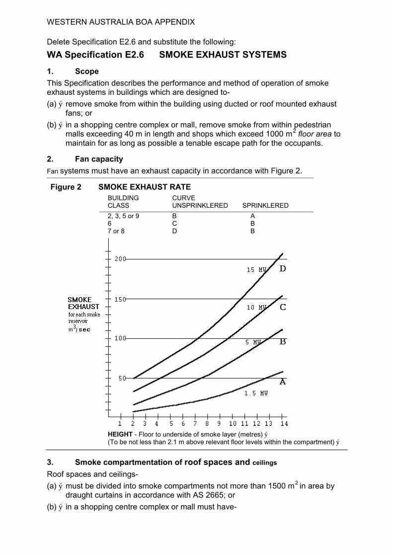
WESTERN AUSTRALIA BOA APPENDIX
Delete Specification E2.6 and substitute the following:
WA Specification E2.6 SMOKE EXHAUST SYSTEMS
1. Scope
This Specification describes the performance and method of operation of smoke exhaust systems in buildings which are designed to-
(a) ý remove smoke from within the building using ducted or roof mounted exhaust fans; or
(b) ý in a shopping centre complex or mall, remove smoke from within pedestrian malls exceeding 40 m in length and shops which exceed 1000 m2 floor area to maintain for as long as possible a tenable escape path for the occupants.
2. Fan capacity
Fan systems must have an exhaust capacity in accordance with Figure 2.
Figure 2 SMOKE EXHAUST RATE BUILDING CURVE CLASS UNSPRINKLERED SPRINKLERED
2, 3, 5 or 9 B A 6 C B 7 or 8 D B
HEIGHT - Floor to underside of smoke layer (metres) ý (To be not less than 2.1 m above relevant floor levels within the compartment) ý
3. Smoke compartmentation of roof spaces and ceilings
Roof spaces and ceilings-
(a) ý must be divided into smoke compartments not more than 1500 m2 in area by draught curtains in accordance with AS 2665; or
(b) ý in a shopping centre complex or mall must have-
WESTERN AUSTRALIA BOA APPENDIX
(i) ý draught curtains, or non-combustible, or toughened or wired glass bulkheads, which extend not less than 1 m beneath any imperforate ceiling, or
(ii) ý ceiling reservoirs of not less than 500 mm deep, each containing a smoke exhaust fan, across the full width of the mall to divide it into compartments not exceeding 40 m in length.
4. Location of fans and discharge
Exhaust fans must be located so as not to cause undue turbulence. and-
(a) ý in a shopping centre complex or mall-
(i) ý be spaced no more than 40 m apart and not more than 20 m from the end of the mall; and
(ii) ý not be located at a mall intersection unless there is an open area where the ceiling is raised not less than 2 m above the ceiling in the mall; and
(iii) ý be located at natural collection points within each smoke compartment for hot smoky gasses having regard to the ceiling geometry and its effect on the migratory path of the smoke.
(b) ý in other buildings be located so that each fan must not serve more than one 1500 m2 roof compartment; and
(c) ý discharge directly to the outside and in a manner that will not spread fire or smoke to adjacent fire-compartments or buildings.
5. Make-up air
Low level fresh air inlet openings or doors must be sized to provide adequate low velocity fresh air make up to satisfy the exhaust performance of the installed smoke exhaust fans, care being exercised in the number and location of such openings and their disturbance of the smoke layer due to turbulence created by the incoming air.
6. Operation of fans
All smoke exhaust fans must start sequentially and be activated by the operation in the area served by the fan of-
(a) ý a sprinkler system;
(b) ý a fire detection and alarm system which complies with Specification E1.7; or
(c) ý a detector system comprising-
(i) ý smoke detectors spaced not more than 30 m apart and 15 m from any curtain, bulkhead or wall and with not less than one detector for each 5:00 m2 of floor area; or
(ii) ý rate of rise heat detectors spaced not more than 15 m apart and 7.5 m from any curtain, bulkhead or wall and with not less than one detector for each 250 m2 of floor area, and not less than 2 detectors located on opposite sides of each fan inlet.
(d) ý in a shopping centre complex or mall -a control system incorporating:
(i) ý Optical smoke detectors at each smoke reservoir fitted with not less than one detector for each 150 m2 of floor area, arranged in a minimum of two groups. Full smoke exhaust must be implemented upon activation of the first alarm group in the respective reservoir. Upon activation of a second detector group and following a 30 second check period an alarm must be transmitted to the Fire Brigade.
WESTERN AUSTRALIA BOA APPENDIX
(ii) ý At each exit from a shop exceeding 1000 m2 in floor area, and at any service desk -a manual break glass fire alarm arranged to immediately activate smoke exhaust fans and. transmit an immediate alarm to the Fire Brigade.
(iii) ý At any service desk and centre managers office - discrete audio/visual alarm activated by the fire alarm system.
-(iv) At the fire indicator board full pilot indication of smoke control equipment operating status and manual override controls.
(v) ý Controls which direct air-handling plant in non fire alarm zones to continue operation to outside air. Air handling plant not providing a smoke exhaust function within a fire alarm zone to stop.
(vi) ý Controls which automatically open main entry doors to malls upon any fire alarm.
7. Protection of wiring
Power supply wiring for roof-mounted exhaust fans must be MIMS (copper) cable or otherwise suitably fire and mechanically protected wiring.
8. Resistance to high temperatures
If not adequately shielded from the airflow-
(a) ý all parts of exhaust fans and other equipment required to operate in a smoke laden environment; and
(b) ý parts of the building required to be smoke-resisting,
must be capable of withstanding a temperature of 2000C for a period of not less than 2 hours.
SECTION F HEALTH AND AMENITY
PART F1 DAMP AND WEATHERPROOFING
Insert in F1 after F1.10 the following:
WA F1.11 Provision of floor wastes (a) ý In a Class 1, 2 or 3 building or Class 4 part, a floor waste or floor waste gulley
must be provided in a-
(i) ý room containing a closet pan;
(ii) ý bathroom; or
(iii) laundry, ý
where the room is located above another sole-occupancy unit. ý
(b) ý The draining of the floor to a shower recess incorporating a floor waste satisfies the requirement of (a).
WESTERN AUSTRALIA BOA APPENDIX
PART F2 SANITARY AND OTHER FACILITIES
Delete F2.4 and substitute the following:
WA F2.4 Facilities for people with disabilities Sanitary facilities must be provided in accordance with WA Table F2.4 in every Class 3, 5, 6, 7, 8 and 9 building that is required by Part D3 to be accessible to people with disabilities.
WA TABLE F2.4 SANITARY FACILITIES FOR PEOPLE WITH DISABILITIES ý CLASS OF BUILDING MINIMUM FACILITY FOR USE BY PEOPLE
WITH DISABILITIES
Class 3 -
In every sole-occupancy unit to which access for (a) one closet pan and washbasin; and people with disabilities is required (b) ý one shower or shower-bath.
Class 5,6,8 and 9 buildings required to be accessible by Part D3 and Table D.3.2 and Class 3 if accommodation is other than in sole-occupancy units, or other parts of the building are required to be accessible-
TOTAL FACILITIES NORMALLY REQUIRED MINIMUM NUMBER FOR USE BY PEOPLE WITH DISABILITIES
Closet pans (including those provided for use by people with disabilities) plus urinals-
1 - 100 ý (a) one unisex facility; or
(b) one closet pan and washbasin for each sex.
101 - 200 (a) 2 unisex facilities; or
(b) ý one closet pan and washbasin for each sex and one unisex facility.
more than 200 ý 3 unisex facilities or one closet pan and washbasin for each sex and two unisex facilities
In all cases, facilities for females must include adequate means for the disposal of sanitary towels.
Baths or showers ý (a) one shower or shower-bath for each 10 or part thereof normally required but not less than one for use by both sexes; and
(b) ýwhere required showers are provided one must comply with AS 1428.1- Shower Recesses and Circulation Spaces for Shower Access.
Insert the following heading for F2.5:
WA F2.5 Construction of sanitary compartments
Delete (b) in F2.5 and substitute the following:
(b) ý Doors -the door of every fully enclosed closet pan compartment must-
(i) ý open outwards; or
(ii) ý be readily removable from the outside.
(c) ý Facilities for people with disabilities- the construction and layout of sanitary compartments, showers and compartments containing washbasins, for use by people with disabilities must comply with AS 1428.1.
WESTERN AUSTRALIA BOA APPENDIX
PART F4 LIGHT AND VENTILATION
Insert the following heading for F4.4:
WA F4.4 Artificial lighting
Insert in F4.4 after (b), the following:
(c) ý Artificial lighting required by this Part must be in accordance with AS 1680.
Insert in F4 after F4.11, the following:
WA F4.12 Reflective glazing (a) ý Interpretation: Reflective glazing means glass or other glazing material that for
one, or a combination of two or more of the following reasons-
(i) ý the properties of the glass or material;
(ii) ý the application to glass or material of a reflective film or any other form of treatment;
(iii) ý the method of construction used in the building component of which the glass or material forms part, ý
has a light or heat reflective value that exceeds 16%. ý
(b) ý Restrictions on use: Reflective glazing used in a door, window or other component of a roof or external wall of every building other than a building of Class 1 or Class 10 must not-
(i) ý cause glare or heat radiation that will have any undue adverse effect on the surrounding environment; and
(ii) ý create any undue traffic hazard.
PART F5 NOISE TRANSMISSION AND INSULATION
Delete F5.1 and insert the following
WA F5.1 Application of Part This Part applies to all Class 1, Class 2 and Class 3 buildings.
Delete F5.3 and insert the following:
WA F5.3 Sound insulation of floors between units A floor separating sole-occupancy units must have an STO not less than 45 and provide a satisfactory level of insulation against impact sound.
WESTERN AUSTRALIA BOA APPENDIX
Insert the following heading for Specification G3.8:
WA Specification G3.8 ý FIRE AND SMOKE CONTROL SYSTEMS IN ATRIUM BUILDINGS
3.2 Operation of atrium mechanical air handling systems
Insert in (d) after (iv), the following:
(v) ý continue to supply air to fire-compartments or storeys other than the fire affected compartment or storey.
Insert in (e) after (ii), the following:
(iii) continue to supply air to fire-compartments or storeys other than the fire affected compartment or storey.
************************************************************************************************

INDEX
A Access and egress: Section D
Access, for people with disabilities: Part D3
Accreditation Certificate, definition: A1.1
Adoption of Standards and other references: A1.2
Air-handling systems, smoke control: E2.1, E2.4
Airlocks: F4.9
Alarm systems, atrium buildings: Spec G3.8
fire detection: Spec E1.7
Alpine area, construction: Part G4
definition: A1.1
Alteration, definition: A1.1
in a united building: A4.2
Alternative exits, discharge: D1.10
distance between: D1.5
Aluminium, construction: B1.3
Amenity and health: Section F
Ancillary provisions: Section G
Application of this Code, to a particular State or Territory: A1.5
Artificial lighting: F4.4
Assembly building, ceiling height: F3.1
definition: A1.1
Attachments, fire-resistance: Spec C1.1
Atrium, buildings, fire and smoke control systems: Spec G3.8
construction: Part G3
dimensions: G3.2
definition: A1.1
exits: G3.7
fire and smoke control systems: G3.8
fire-isolated exits, smoke control: E2.2
smoke control: E2.1
Atrium well, definition: A1.1
Attic rooms, ceiling height: F3.2
Auditorium, discharge of exits: D1.10
theatres and public halls: Part H1
Automatic, definition: A1.1
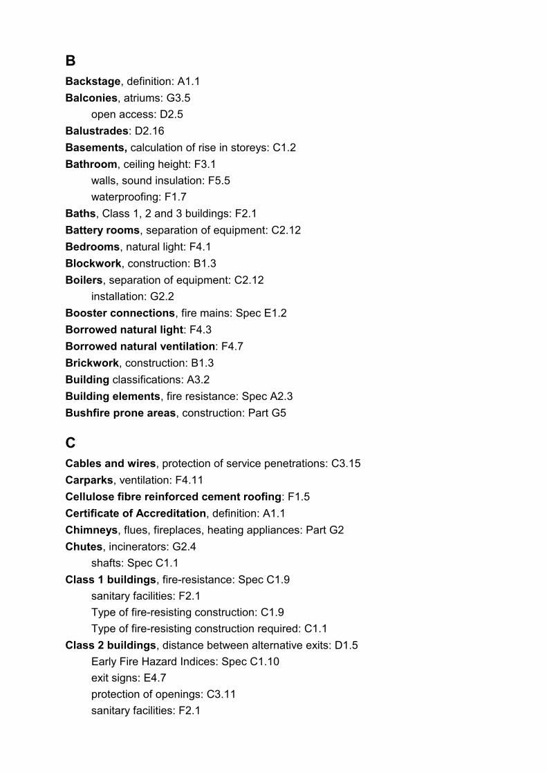
C
B Backstage, definition: A1.1
Balconies, atriums: G3.5
open access: D2.5
Balustrades: D2.16
Basements, calculation of rise in storeys: C1.2
Bathroom, ceiling height: F3.1
walls, sound insulation: F5.5
waterproofing: F1.7
Baths, Class 1, 2 and 3 buildings: F2.1
Battery rooms, separation of equipment: C2.12
Bedrooms, natural light: F4.1
Blockwork, construction: B1.3
Boilers, separation of equipment: C2.12
installation: G2.2
Booster connections, fire mains: Spec E1.2
Borrowed natural light: F4.3
Borrowed natural ventilation: F4.7
Brickwork, construction: B1.3
Building classifications: A3.2
Building elements, fire resistance: Spec A2.3
Bushfire prone areas, construction: Part G5
Cables and wires, protection of service penetrations: C3.15
Carparks, ventilation: F4.11
Cellulose fibre reinforced cement roofing: F1.5
Certificate of Accreditation, definition: A1.1
Chimneys, flues, fireplaces, heating appliances: Part G2
Chutes, incinerators: G2.4
shafts: Spec C1.1
Class 1 buildings, fire-resistance: Spec C1.9
sanitary facilities: F2.1
Type of fire-resisting construction: C1.9
Type of fire-resisting construction required: C1.1
Class 2 buildings, distance between alternative exits: D1.5
Early Fire Hazard Indices: Spec C1.10
exit signs: E4.7
protection of openings: C3.11
sanitary facilities: F2.1
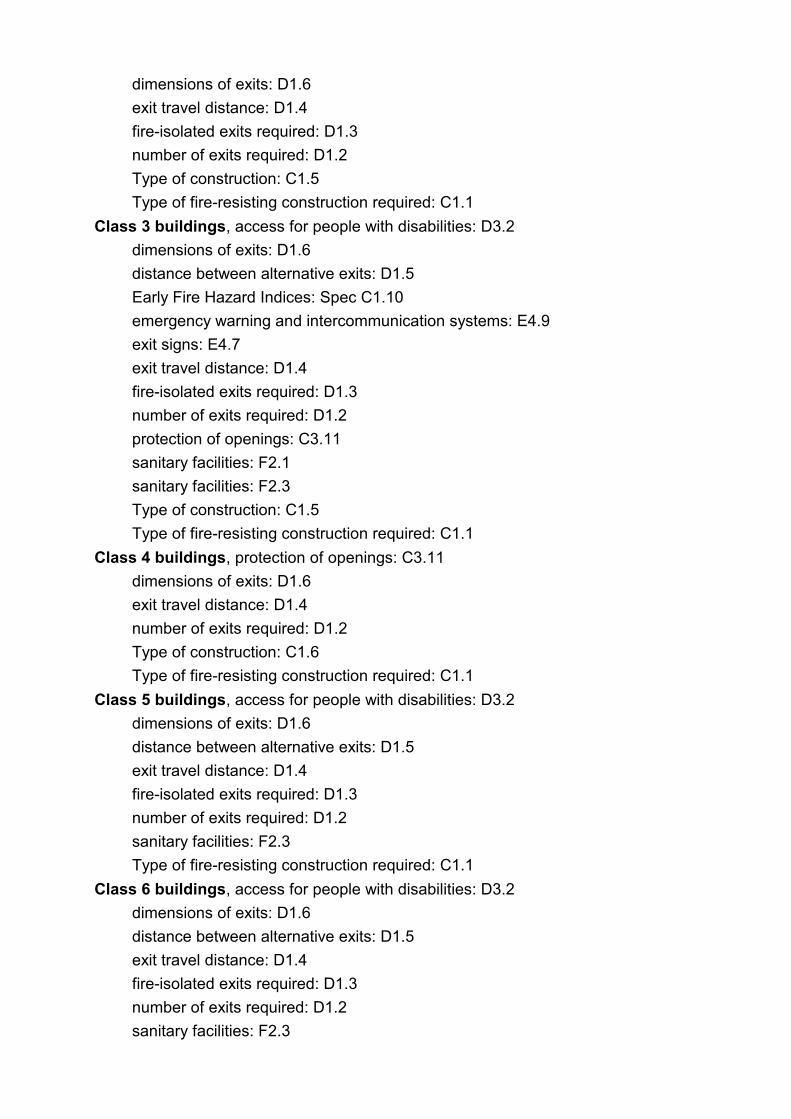
dimensions of exits: D1.6
exit travel distance: D1.4
fire-isolated exits required: D1.3
number of exits required: D1.2
Type of construction: C1.5
Type of fire-resisting construction required: C1.1
Class 3 buildings, access for people with disabilities: D3.2
dimensions of exits: D1.6
distance between alternative exits: D1.5
Early Fire Hazard Indices: Spec C1.10
emergency warning and intercommunication systems: E4.9
exit signs: E4.7
exit travel distance: D1.4
fire-isolated exits required: D1.3
number of exits required: D1.2
protection of openings: C3.11
sanitary facilities: F2.1
sanitary facilities: F2.3
Type of construction: C1.5
Type of fire-resisting construction required: C1.1
Class 4 buildings, protection of openings: C3.11
dimensions of exits: D1.6
exit travel distance: D1.4
number of exits required: D1.2
Type of construction: C1.6
Type of fire-resisting construction required: C1.1
Class 5 buildings, access for people with disabilities: D3.2
dimensions of exits: D1.6
distance between alternative exits: D1.5
exit travel distance: D1.4
fire-isolated exits required: D1.3
number of exits required: D1.2
sanitary facilities: F2.3
Type of fire-resisting construction required: C1.1
Class 6 buildings, access for people with disabilities: D3.2
dimensions of exits: D1.6
distance between alternative exits: D1.5
exit travel distance: D1.4
fire-isolated exits required: D1.3
number of exits required: D1.2
sanitary facilities: F2.3

Type of fire-resisting construction required: C1.1
Class 7 buildings, access for people with disabilities: D3.2
calculation of rise in storeys: C1.2
dimensions of exits: D1.6
distance between alternative exits: D1.5
exit travel distance: D1.4
fire-isolated exits required: D1.3
fixed platforms, walkways and ladders: D2.18
number of exits required: D1.2
sanitary facilities: F2.3
Type of fire-resisting construction required: C1.1
weatherproofing: F1.4
Class 8 buildings, access for people with disabilities: D3.2
calculation of rise in storeys: C1.2
dimensions of exits: D1.6
distance between alternative exits: D1.5
exit travel distance: D1.4
fire-isolated exits required: D1.3
fixed platforms, walkways and ladders: D2.18
number of exits required: D1.2
sanitary facilities: F2.3
type of fire-resisting construction required: C1.1
weatherproofing: F1.4
Class 9 buildings, access for people with disabilities: D3.2
Early Fire Hazard Indices: Spec C1.10
dimensions of exits: D1.6
distance between alternative exits: D1.5
exit travel distance: D1.4
fire-isolated exits required: D1.3
number of exits required: D1.2
sanitary facilities: F2.3
Class 9 buildings, Type of fire-resisting construction required: C1.1
Class 9a buildings, compartmentation: C2.5
emergency warning and intercommunication systems: E4.9
fire detection and alarm systems: Spec E1.7
stairway landings: D2.14
Class 9b buildings, emergency warning and intercommunication systems: E4.9
Class 10 buildings, fire-resistance: Spec C1.9
Type of fire-resisting construction: C1.9
weatherproofing: F1.4
Type of fire-resisting construction required: C1.1

Classification, of buildings: A3.2
principles: A3.1
multiple, Type of construction: C1.3
multiple: A3.3
Classifications, horizontal separation: C2.8
Clinic, ceiling height: F3.1
Closet pans, sanitary facilities: Part F2
Clothes washing facilities, Class 1, 2 and 3 buildings : F2.1
Combustible, definition: A1.1
Common wall, definition: A1.1
Class 1 buildings, fire-resistance: Spec C1.9 ý
Class 10 buildings, fire-resistance: Spec C1.9 ý
fire-resistance: Spec C1.1 ý
Compartmentation, Class 9a buildings: C2.5
floor area limitations: C2.2
large isolated buildings: C2.3
separation of openings in external walls: C3.3
vertical separation: C2.6
Components, minor structures: Part G1
Composite steel and concrete, construction: B1.3
Concrete roofing tiles, installation: B1.3, F1.5
Concrete structures, fire-resistance level: Spec A2.3
construction: B1.3
Connection of storeys, non-required stairways: D1.12
Construction, in bushfire prone areas: Part G5
of exits: Part D2 ý
deemed to satisfy structural requirements: B1.3 ý
sound transmission: Spec F5.2 ý
structural requirements: B1.3 ý
Control centres, fire emergency: Spec E1.8
Control joints, protection of openings: C3.1
Corridor, ceiling height: F3.1
Curtain wall, definition: A1.1
fire-resistance: Spec C1.1
vertical separation: C2.6
Curtains, proscenium walls, theatres and public halls: Spec H1.3
D Damp and weatherproofing: Part F1
Damp-proof course,

mortars: F1.8
termite shields: F1.9
Damp-proofing, floors on ground: F1.10
Dampness, on building site: F1.2
Dead load, structural requirements: B1.2
Delivery room, ceiling height: F3.1
Demolition: Part B2
Design suitability: A2.2
Dimensions of exits: D1.6
Direction signs, exits: E4.6
Disabled persons, access: Part D3
sanitary facilities: F2.4
Discharge from exits: D1.10
Distance, between alternative exits: D1.5
of travel to exits: D1.4
measurement, exits: D1.14, D1.15
Distribution boards, in exits and paths of travel: D2.7
Domestic-type heating appliances: G2.2
Domestic-type water heaters, access: G1.3
Doors, Class 2, 3 and 4 buildings, protection: C3.11
lift landing, separation of shafts: C2.10
smoke control: E2.3
Doorways, construction in alpine areas: G4.3
in fire walls: C3.5
lift landing, protection: C3.10
methods of protection of openings: C3.4
protection in horizontal exits: C3.7
protection of openings: C3.1
required exits: D2.19
Drainage, domestic-type water heaters: G1.3
swimming pools: G1.1
stormwater: F1.1
E Early childhood centre, definition: A1.1
Early Fire Hazard Indices: C1.10, Spec C1.10
determination: A2.4
test for assemblies: Spec A2.4
Earthquake load, structural requirements: B1.2
Earthwall construction, structural provisions: B1.3

Effective height, definition: A1.1
Electrical service, switchboard, separation: C2.12
meters in exits and paths of travel: D2.7
switches and outlets, protection of service: C3.15
Emergency generators, separation of equipment: C2.12
Emergency lifts: E3.4
Emergency lighting, buildings in alpine areas: G4.4
design: E4.4 ý
exit signs and warning systems: Part E4 ý
requirements: E4.2 ý
Emergency warning and intercommunication systems: E4.9
Enclosure, of space under stairs and ramps: D2.8
Equipment, fire-fighting: Part E1
separation: C2.12
Escalators, non-required: D1.12 Spec D1.12
Escape provisions: Part D1
Evacuation warning systems, atrium buildings: G3.8
Evidence of fire resistance, building elements: A2.3
Evidence of suitability of materials, form of construction or design: A2.2
Exhaust systems, smoke control: E2.1, Spec E2.6
theatres and public halls: Spec H1.2
Exhaust ventilation: F4.9
Exit, atriums: G3.7
construction: Part D2 ý
definition: A1.1 ý
dimensions: D1.6 ý
discharge: D1.10 ý
discharge in alpine areas: G4.6 ý
distance between alternatives: D1.5 ý
doors, fire emergency control centres: Spec E1.8 ý
doorways and doors: D2.19 ý
fire-isolated, protection of openings: C3.8 ý
fire-isolated, re-entry: D2.22 ý
fire-isolated, travel: D1.7 ý
horizontal: D1.11 ý
installations and services: D2.7 ý
number required: D1.2 ý
power-operated doors: D2.19 ý
revolving doors: D2.19 ý
roller shutters: D2.19 ý
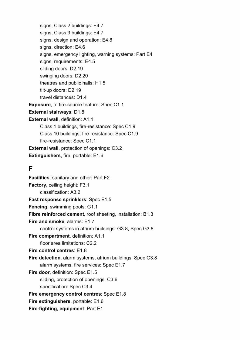
signs, Class 2 buildings: E4.7
signs, Class 3 buildings: E4.7
signs, design and operation: E4.8
signs, direction: E4.6
signs, emergency lighting, warning systems: Part E4
signs, requirements: E4.5
sliding doors: D2.19
swinging doors: D2.20
theatres and public halls: H1.5
tilt-up doors: D2.19
travel distances: D1.4
Exposure, to fire-source feature: Spec C1.1
External stairways: D1.8
External wall, definition: A1.1
Class 1 buildings, fire-resistance: Spec C1.9
Class 10 buildings, fire-resistance: Spec C1.9
fire-resistance: Spec C1.1
External wall, protection of openings: C3.2
Extinguishers, fire, portable: E1.6
F Facilities, sanitary and other: Part F2
Factory, ceiling height: F3.1
classification: A3.2
Fast response sprinklers: Spec E1.5
Fencing, swimming pools: G1.1
Fibre reinforced cement, roof sheeting, installation: B1.3
Fire and smoke, alarms: E1.7
control systems in atrium buildings: G3.8, Spec G3.8
Fire compartment, definition: A1.1
floor area limitations: C2.2
Fire control centres: E1.8
Fire detection, alarm systems, atrium buildings: Spec G3.8
alarm systems, fire services: Spec E1.7
Fire door, definition: Spec E1.5
sliding, protection of openings: C3.6
specification: Spec C3.4
Fire emergency control centres: Spec E1.8
Fire extinguishers, portable: E1.6
Fire-fighting, equipment: Part E1

services, alpine areas: G4.7
Fire hose reels: E1.4
Fire hydrants: E1.3
Fire-isolated exits, Early Fire Hazard Indices: Spec C1.10
protection of openings: C3.8 ý
protection of service penetrations: C3.9 ý
re-entry: D2.22 ý
requirements: D1.3 ý
smoke control: E2.2 ý
travel: D1.7 ý
Fire-isolated lift shafts, protection of openings: C3.10 Fire-isolated
passageway, definition: A1.1
construction: D2.11
Fire-isolated ramp, definition: A1.1
construction: D2.2
Fire-isolated stairway, definition: A1.1
construction: D2.2
Fire main, definition: A1.1
water supply services: E1.2 and Spec E1.2
Fire orders, alpine areas: G4.9
Fireplaces, construction: G2.3
heating appliances, chimneys and flues: Part G2
Fire precautions, during construction: E1.9
Fire protection, support of another part: Spec C1.1
Fire-protective covering, definition: A1.1
Fire provisions, special hazards: E1.10
Fire pumps, fire mains and water supply services: Spec E1.2
Fire-resistance and stability: Part C1
Fire-resistance, attachments: Spec C1.1
building elements: A2.3, Spec A2.3, Spec C1.1 ý
Class 1 and 10 buildings: Spec C1.9 ý
common walls: Spec C1.1 ý
external walls: Spec C1.1 ý
fire walls: Spec C1.1 ý
floors: Spec C1.1 ý
indoor sports stadiums: Spec C1.1 ý
internal walls: Spec C1.1 ý
lintels: Spec C1.1 ý
masonry-veneer walls: Spec C1.1 ý
mezzanine floors: Spec C1.1 ý
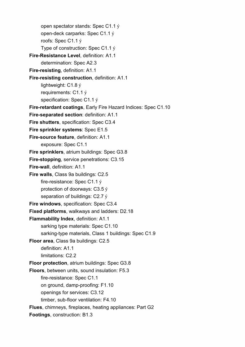
open spectator stands: Spec C1.1 ý
open-deck carparks: Spec C1.1 ý
roofs: Spec C1.1 ý
Type of construction: Spec C1.1 ý
Fire-Resistance Level, definition: A1.1
determination: Spec A2.3
Fire-resisting, definition: A1.1
Fire-resisting construction, definition: A1.1
lightweight: C1.8 ý
requirements: C1.1 ý
specification: Spec C1.1 ý
Fire-retardant coatings, Early Fire Hazard Indices: Spec C1.10
Fire-separated section: definition: A1.1
Fire shutters, specification: Spec C3.4
Fire sprinkler systems: Spec E1.5
Fire-source feature, definition: A1.1
exposure: Spec C1.1
Fire sprinklers, atrium buildings: Spec G3.8
Fire-stopping, service penetrations: C3.15
Fire-wall, definition: A1.1
Fire walls, Class 9a buildings: C2.5
fire-resistance: Spec C1.1 ý
protection of doorways: C3.5 ý
separation of buildings: C2.7 ý
Fire windows, specification: Spec C3.4
Fixed platforms, walkways and ladders: D2.18
Flammability Index, definition: A1.1
sarking type materials: Spec C1.10
sarking-type materials, Class 1 buildings: Spec C1.9
Floor area, Class 9a buildings: C2.5
definition: A1.1
limitations: C2.2
Floor protection, atrium buildings: Spec G3.8
Floors, between units, sound insulation: F5.3
fire-resistance: Spec C1.1
on ground, damp-proofing: F1.10
openings for services: C3.12
timber, sub-floor ventilation: F4.10
Flues, chimneys, fireplaces, heating appliances: Part G2
Footings, construction: B1.3

I
Foundation, definition: A1.1
Fuel services, exits and paths of travel: D2.7
G Garage, weatherproofing: F1.4
Gas and other fuel services, exits and paths of travel: D2.7
Glass, installation: B1.3
GRP sheeting, roof construction: B1.3
Gypsum plaster, fire-resistance level: Spec A2.3
H Habitable room, ceiling height: F3.1
definition: A1.1
natural light: F4.1
walls, sound insulation: F5.5
Handrails, construction: D2.17
width of stairways: D2.9
Health and amenity: Section F
Health-care building, definition: A1.1
Hearth, construction of fireplaces: G2.3
Heaters, appliances, installation: G2.2
Heating appliances, fireplaces, chimneys and flues: Part G2
Height of rooms: F3.1
Horizontal exit, definition: A1.1
protection of doorways: C3.7
requirements: D1.11
Hose reels: E1.4
Hydrant, definition: A1.1
fire: E1.3
Impact sound, test of equivalence: F5.5, Spec F5.5
Incinerator, chutes, exits and paths of travel: D2.7
rooms: G2.4
Indoor sports stadiums, fire-resistance: Spec C1.1
Type of construction: C1.7
Inferior wall, definition: Spec E1.5
Installations, in exits, paths of travel: D2.7
safety, maintenance: Part E5
Insulation, fire-resistance level, definition: A1.1

L
Insulation, noise: Part F5
Integrity, fire-resistance level, definition: A1.1
Intercommunication systems, emergency warning: E4.9
Internal wall, definition: A1.1
fire-resistance: Spec C1.1
J
K Kitchen, ceiling height: F3.1
sinks, sanitary and other facilities: F2.1
walls, sound insulation: F5.5
Ladders, fixed platforms and walkways: D2.18
Land, drainage: F1.3
Landings, dimensions and construction: D2.14
Large isolated buildings, compartmentation: C2.3
Latches, door, operation: D2.21
Laundry, ceiling height: F3.1
walls, sound insulation: F5.5 ý
waterproofing: F1.7 ý
Lift, emergency: E3.4
indicator panels, protection: C3.10
installations: Part E3
landing doors, separation of shafts: C2.10
motor room, separation: C2.12
motor rooms, fixed platforms, walkways and ladders: D2.18
shafts, lightweight construction: Spec C1.8
shafts, protection of openings: C3.10
shafts, separation: C2.10
shafts, stairways: C2.11
stretcher facility: E3.2
use in fire: E3.3
Light, artificial: F4.4
natural: F4.1, F4.3
Lighting, fire emergency control centres: Spec E1.8
Lightweight construction, definition: A1.1
structural tests: Spec C1.8 ý
requirements: C1.8 ý

Lintels, fire-resistance: Spec C1.1
Live load, structural requirements: B1.2
Loadbearing, definition: A1.1
Loads, structural requirements: B1.2
Lobby, smoke, construction: D2.6
smoke, required: D1.7
Locks, operation of door latch: D2.21
Lofts and platforms, theatres and public halls: H1.6
M Maintenance of safety installations: Part E5
Masonry, fire-resistance level: Spec A2.3
Masonry-veneer walls, fire-resistance: Spec C1.1
Materials, Early Fire Hazard Indices: Spec C1.10
structural requirements: B1.1
suitability: A2.1
Measurement of distance, emergency lighting: E4.3
exits: D1.14, D1.15
Mechanical ventilation, theatres and public halls: Spec H1.3
Metal pipes, protection of service penetrations: C3.15
Metal roofing, installation: B1.3
weatherproofing: F1.5
Mezzanine floor, definition: A1.1
fire-resistance: Spec C1.1
Minor structures and components: Part G1
Mixed types of construction, fire-resistance: C1.4
Moisture barriers, floor on ground: F1.10
Mortars, damp-proof: F1.8
Multiple classification, interpretation: A3.3
Type of construction: C1.3
N Natural light: F4.1, F4.3
Natural smoke venting: E2.3
Natural ventilation: F4.6
Noise transmission, insulation: Part F5
Non-combustible, definition: A1.1
Non-fire-isolated stairways and ramps, construction: D2.3
travel: D1.9
Non-required stairways, ramps and escalators: D1.12
Number, persons accommodated: D1.13
O Occupant density, number of persons: D1.13
Office, ceiling height: F3.1
classification: A3.2
Oil-fired appliances, domestic: G2.2
Open access ramps, balconies: D2.5
Open-deck carpark, compartmentation: C2.1
definition: A1.1
fire-resistance: Spec C1.1
Open-deck carpark, vertical separation: C2.6
weatherproofing: F1.4
Open fireplaces, construction: G2.3
Open garage, definition: A1.1
Open space, definition: A1.1
large isolated buildings: C2.3, C2.4
roof: D2.12
Open spectator stand, compartmentation: C2.4
definition: A1.1
dimensions of exits: D1.6
discharge of exits: D1.10
fire-resistance: Spec C1.1
number of exits required: D1.2
openings in external walls: C3.2
Type of construction: C1.7
vertical separation: C2.6
weatherproofing: F1.4
Openings, for service installations: C3.14, C3.15
in fire emergency control centres: Spec E1.8
in fire-isolated lift shafts: C3.10
in floors for services: C3.12
in proscenium walls, theatres and public halls: Spec H1.3
in shafts, protection: C3.13
protection: Part C3
protection in fire-isolated exits: C3.8
separation of fire compartments: C3.3
Operating theatre, ceiling height: F3.1
Operation of door latch: D2.21
P Panel wall, definition: A1.1
fire-resistance: Spec C1.1
Particleboard structural flooring, installation: B1.3
Passageway, ceiling height: F3.1
fire-isolated, construction: D2.11
Paths of travel, installations and services: D2.7
Patient care area, ceiling height: F3.1
compartmentation: C2.5
definition: A1.1
dimensions of exits: D1.6
Pedestrian ramps, construction: D2.10
Penetrations: C3.15
for services, protection: C3.14, C3.15, Spec C3.15
Persons accommodated, number: D1.13
Piling, construction: B1.3
Pipes, soil and waste, sound insulation: F5.6
Plant rooms, fixed platforms, walkways and ladders: D2.18
fire separation: C2.12
Plaster, fire-resistance level: Spec A2.3
Platforms and lofts, theatres and public halls: H1.6
Pliable roof sarking: F1.6
Pools, swimming: G1.1
Portable fire extinguishers: E1.6
Power supply, fire emergency control centres: Spec E1.8
Power-operated doors, required exits: D2.19
Precautions against fire, during construction: E1.9
Pressurisation systems, smoke control: E2.7
Principles of classification: A3.1
Private garage, definition: A1.1
Professional engineer, definition: A1.1
Proscenium walls, construction: Spec H1.3
theatres and public halls: H1.3
Protection of openings: Part C3
in shafts: C3.13
methods: C3.4
service penetrations: C3.14, C3.15
Provision for escape: Part D1
Provision for special hazards, fire fighting: E1.10
Public carpark, definition: A1.1

ventilation: F4.11
Public corridor, definition: A1.1
Public hall, ceiling height: F3.1
emergency warning and intercommunication systems: E4.9
stages, theatres: Part H1
Pumps, sound insulation: F5.7
PVC sheeting, roof construction: B1.3
Q
R Ramps, enclosure of space under: D2.8
external, alpine areas: G4.5
fire-isolated, construction: D2.2
non-fire-isolated, travel: D1.9
non-fire-isolated, construction: D2.3
non-required: D1.12 Spec D1.12
pedestrian, construction: D2.10
Re-entry from fire-isolated exits: D2.22
Referenced Standards: A1.3
Refrigerated chambers, strong rooms and vaults: G1.2
Registered Testing Authority, definition: A1.1
fire-resistance level: Spec A2.3
Required, definition: A1.1
Resistance to the incipient spread of fire, definition: A1.1
Revolving doors, required exits: D2.19
Rigging lofts, theatres and public halls: H1.6
Rise in storeys, calculation: C1.2
definition: A1.1
Risers and treads, dimensions: D2.13
Roller shutters, required exits: D2.19
Roof, as open space: D2.12
construction: B1.3
coverings: F1.5
fire-resistance: Spec C1.1
protection, atrium buildings: Spec G3.8
sarking: F1.6
separation, atriums: G3.6
structures, fire-resistance concession: Spec C1.1
vents, smoke control: E2.1
vents, smoke control: E2.5
weatherproofing: F1.4
Room height: F3.1
Room sizes: Part F3
fire emergency control centres: Spec E1.8
S Safety fencing, swimming pools: G1.1
Safety installations, maintenance: E5.2
Sanitary compartment, construction: F2.5
definition: A1.1
dimensions of doors: D1.6
operation of door latch: D2.21
waterproofing: F1.7
weatherproofing: F1.4
Sanitary and other facilities: Part F2
Sarking, roof: F1.6
Sarking-type material, definition: A1.1
Early Fire Hazard Indices: Spec C1.10
Class 1 buildings: Spec C1.9
School, definition: A1.1
dimensions of exits: D1.6
School classroom, ceiling height: F3.1
natural light: F4.1
Seating area, theatres and public halls: H1.4
Seismic load, structural requirements: B1.2
Self-closing, definition: A1.1
Separation by fire walls: C2.7
Separation, of classifications, horizontal: C2.8
of classifications, vertical: C2.9
of equipment: C2.12
of lift shafts: C2.10
of rising and descending stair flights: D2.4
of plantrooms: C2.12
Service penetrations, in fire-isolated exits: C3.9
protection of openings: C3.14, C3.15
specification: Spec C3.15
Service station, definition: A1.1
Service units, equipment, calculation of rise in storeys: C1.2
Serviceability, structural: B1.1
Services, protection of openings in floors: C3.12
Shaft, definition: A1.1
lightweight construction: Spec C1.8
protection of openings: C3.13
separation of lifts: C2.10
Shop, ceiling height: F3.1
Shopping centres, compartmentation: C2.3
smoke control: E2.1
Shower enclosures, waterproofing: F1.7
Showers, Class 1, 2 and 3 buildings: F2.1
Signs, fire emergency control centres: Spec E1.8
Site, dampness: F1.2
definition: A1.1
Size of rooms: Part F3
Sliding doors, required exits: D2.19
Sliding fire doors, protection of openings: C3.6
Sloping ceilings, height: F3.2
Smoke and fire alarms: E1.7
Smoke and heat vent, definition: A1.1
large isolated buildings: C2.3 ý
requirements: E2.5 ý
Smoke control: Part E2
air-handling systems: E2.4
atriums: G3.8, Spec G3.8
fire-isolated exits: E2.2
Smoke detectors, location: Spec E1.7
Smoke Developed Indices: Spec C1.10
Smoke Developed Index, definition: A1.1
requirements: C1.10, Spec C1.10
Smoke doors, specification: Spec C3.4
Smoke exhaust systems: E2.6
large isolated buildings: C2.3
separation of equipment: C2.12
Smoke lobby, construction: D2.6
required: D1.7
Smoke-proof walls, Class 9a buildings: C2.5
Smoke venting, natural: E2.3
Snow, areas, construction: Part G4
load, structural requirements: B1.2
Soil and waste pipes, sound insulation: F5.6
Soil treatment, against termites: B1.3
Sole-occupancy unit, definition: A1.1
Solid-fuel burning appliances, domestic-type: G2.2
Sound insulation, floors between units: F5.3
impact, test of equivalence: Spec F5.5 ý
pumps: F5.7 ý
walls between units: F5.4 ý
waste and soil pipes: F5.6 ý
Sound level, fire emergency control centres: Spec E1.8
Sound transmission and insulation: Part F5
Sound Transmission Class, interpretation: F5.2
Space under stairs and ramps, enclosure: D2.8
Spandrels, vertical separation: C2.6
Special hazards, fire provisions: E1.10
Special use buildings: Section H
Spread of Flame Indices, definition: A1.1
requirements: C1.10, Spec C1.10
Sprinkler system, definition: A1.1
fire suppression: E1.5, Spec E1.5
large isolated buildings: C2.3
valve equipment, separation: C2.12
Stage, class 9b buildings, definition: A1.1
theatres, public halls: Part H1
Stair, dimensions, treads and risers: D2.13
enclosure of space under: D2.8
flights, rising and descending, separation: D2.4
pressurisation systems, atrium buildings: G3.8
pressurisation, separation of equipment: C2.12
shafts, lightweight construction: Spec C1.8
Stairway, external: D1.8
fire-isolated, construction: D2.2
landings, construction: D2.14
lift shafts: C2.11
non-fire-isolated, construction: D2.3
non-fire-isolated, travel: D1.9
non-required: D1.12 Spec D1.12
width: D2.9
Standard Fire Test, definition: A1.1
Fire-Resistance Level: Spec A2.3
Standards, adoption: A1.2, A1.3, Spec A1.3

STC, ratings for building elements: Spec F5.2
Steel, construction: B1.3
fire-resisting construction: Spec C1.1
Storey, calculation of rise: C1.2
definition: A1.1
Stormwater drainage: F1.1
Stretcher facility, in lifts: E3.2
Strongroom, operation of door latch: D2.21
refrigerated chambers and vaults: G1.2
Structural adequacy, Fire-Resistance Level, definition: A1.1
Structural member, definition: A1.1
Fire-Resistance Level: Spec A2.3
Structural performance: B1.1
Structural Provisions: Part B1
Structural steel members, Fire-Resistance Level: Spec C1.1, Spec A2.3
Structural tests, for lightweight construction: Spec C1.8
Structures, trafficable, alpine areas: G4.7
Sub-floor ventilation: F4.10
Subsoil drainage: F1.2
Suitability, of materials, construction or design: A2.1
Supporting parts, of buildings, fire protection: Spec C1.1
Swimming pool, definition: A1.1
requirements: G1.1
Swinging doors, required exits: D2.20
T Telecommunication equipment, in exits, paths of travel: D2.7
Termite shields, damp-proof course: F1.9
Termites, protection: B1.3
Terracotta, roof tiles, installation: B1.3
weatherproofing: F1.5
Theatre, ceiling height: F3.1
discharge of exits: D1.10
emergency warning and intercommunication systems: E4.9
stages and public halls: Part H1
Thresholds, requirements: D2.15
Tilt-up doors, required exits: D2.19
Timber, construction: B1.3
floors, sub-floor ventilation: F4.10
Travel, distance, to exits: D1.4

V
via fire-isolated exits: D1.7
via non-fire-isolated stairways and ramps: D1.9
Treads and risers, dimensions: D2.13
Treatment room, ceiling height: F3.1
Type of construction, required: C1.1
fire-resistance: Spec C1.1 ý
Class 1 buildings: C1.9 ý
Class 4 buildings: C1.6 ý
Class 10 buildings: C1.9 ý
indoor sports stadiums: C1.7 ý
mixed, fire-resistance: C1.4 ý
open spectator stands: C1.7 ý
U United buildings: A4.1
alterations: A4.2
Urinals,
dimensions: F2.6
location: F4.8
sanitary facilities: Part F2
Valves, fire mains: Spec E1.2
Vapour barriers, floor on ground: F1.10
Vaults, operation of door latch: D2.21
strongrooms and refrigerated chambers: G1.2
Vehicular access, large isolated buildings: C2.3, C2.4
Ventilation and light: Part F4
Ventilation, of rooms: F4.5
exhaust: F4.9
fire emergency control centres: Spec E1.8
natural: F4.6
public carparks: F4.11
smoke: Part E2
sub-floor: F4.10
theatres and public halls: Spec H1.3
Ventilators, protection of openings: C3.1
Vents, roof, smoke control: E2.5
Vertical separation, of classifications: C2.9
compartmentation: C2.6

Volume, fire compartments: C2.2
W Waiting room, ceiling height: F3.1
Walkways, fixed platforms and ladders: D2.18
Walls, between units, sound insulation: F5.4
non-loadbearing, lightweight construction: Spec C1.8
weatherproofing: F1.4
Warehouse, ceiling height: F3.1
Warning sign, use of lifts in fire: E3.3
sliding fire door: C3.6
Warning systems, emergency lighting, exit signs: Part E4
Washbasins, dimensions: F2.6
Waste and soil pipes, sound insulation: F5.6
Water closets, location: F4.8
waterproofing: F1.7
Water heaters, household type, access: G1.3
Water supply, fire mains: E1.2, Spec E1.2
fire sprinklers: Spec E1.5
Waterproofing, of wet areas in buildings: F1.7
Weatherproofing, dampness: Part F1
of roofs and walls: F1.4
Weep holes, protection of openings: C3.1
Wet areas, in buildings, waterproofing: F1.7
Width, of stairways: D2.9
Wind load, structural requirements: B1.2
Window, definition: A1.1
methods of protection of openings: C3.4
natural light: F4.2, F4.3
protection of openings: C3.1
smoke control: E2.1, E2.3
Wires and cables, protection of service penetrations: C3.15
Y
Z ***************************************************************************************
X