Introduction to Rubber Processing
45
Introduction to rubber processing and safety issues This section provides details of the mechanical processes involved in the production of various types of rubber goods. Details are included of the various safety and fire and explosion hazards but there are only brief references made to the health risks. For information on health risks see health and safety topics . The industry uses very powerful machinery with the potential to cause fatal and serious injuries. There are established industry safeguarding standards for two-roll mills, internal mixers and calenders. Many serious accidents take place during repairs or to clear blockages etc. and there must be procedures in place to ensure that safe interventions take place. Contents Compounding (including powder handling, mixing and milling) Extrusion Calendering Cloth coating Fabrication (including tank lining, roller covering, and hose winding) Vulcanisation (including presses, autoclaves and continuous vulcanisation) Latex processing Polyurethanes (including PU foam production, reconstituted foam and conversion and rigid urethanes) Tyre building Tyre retreading
-
Upload
daniel-munoz -
Category
Documents
-
view
45 -
download
3
description
ADVANCE RUBBER COMPOSITES
Transcript of Introduction to Rubber Processing
Introduction to rubber processing and safety issues This section provides details of the mechanical processes involved in the production of various types of rubber goods. Details are included of the various safety and fire and explosion hazards but there are only
brief references made to the health risks. For information on health risks see health and safety topics.
The industry uses very powerful machinery with the potential to cause fatal and serious injuries. There are established industry safeguarding standards for two-roll mills, internal mixers and calenders. Many serious accidents take place during repairs or to clear blockages etc. and there must be procedures in place to
ensure that safe interventions take place.
Contents Compounding (including powder handling, mixing and milling)
Extrusion
Calendering
Cloth coating
Fabrication (including tank lining, roller covering, and hose winding)
Vulcanisation (including presses, autoclaves and continuous vulcanisation)
Latex processing
Polyurethanes (including PU foam production, reconstituted foam and conversion and
rigid urethanes)
Tyre building
Tyre retreading
Compounding - powder handling, mixing and milling
Introduction
Compounding involves the measuring and mixing together of
raw rubber, process oils, carbon black, bulk fillers, and rubber
chemicals in pre-determined proportions, termed formulations.
A rubber compounder can typically use between 100 and 200
different ingredients to mix a range of formulations. The
finished mixture is known as compound and is the material
that is processed into rubber articles by moulding, extrusion,
calendering etc.
Bale cutting
Before being added to the mixer the rubber may need to
be cut into small pieces on a bale cutter or guillotine.
These are usually down stroking machines, which should
be securely fenced with interlocking access gates. Feed
openings/tunnels should also meet safety reach
distances.
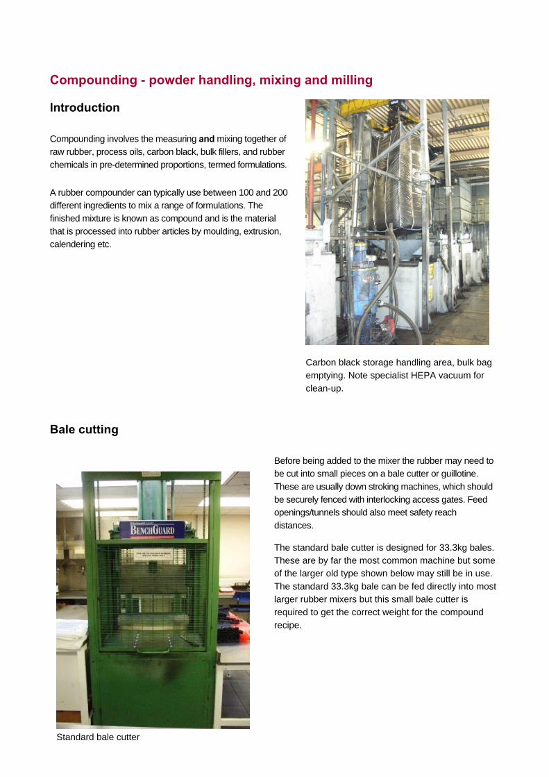
The standard bale cutter is designed for 33.3kg bales. These are by far the most common machine but some of the larger old type shown below may still be in use.
The standard 33.3kg bale can be fed directly into most larger rubber mixers but this small bale cutter is required to get the correct weight for the compound
recipe.
Carbon black storage handling area, bulk bagemptying. Note specialist HEPA vacuum for
clean-up.
Standard bale cutter
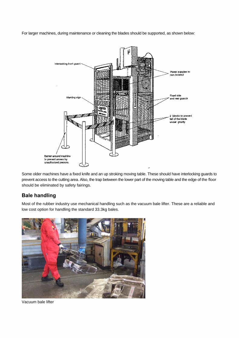
For larger machines, during maintenance or cleaning the blades should be supported, as shown below:
Some older machines have a fixed knife and an up stroking moving table. These should have interlocking guards to
prevent access to the cutting area. Also, the trap between the lower part of the moving table and the edge of the floor
should be eliminated by safety fairings.
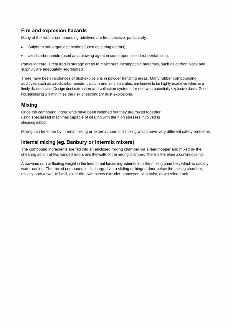
Bale handling Most of the rubber industry use mechanical handling such as the vacuum bale lifter. These are a reliable and
low cost option for handling the standard 33.3kg bales.
Vacuum bale lifter
Fire and explosion hazards Many of the rubber compounding additives are fire sensitive, particularly:
Sulphurs and organic peroxides (used as curing agents);
azodicarbonamide (used as a blowing agent in some open celled rubber/lattices).
Particular care is required in storage areas to make sure incompatible materials, such as carbon black and sulphur, are adequately segregated.
There have been incidences of dust explosions in powder handling areas. Many rubber compounding additives such as azodicarbonamide, calcium and zinc stearates, are known to be highly explosive when in a finely divided state. Design dust extraction and collection systems for use with potentially explosive dusts. Good
housekeeping will minimise the risk of secondary dust explosions.
Mixing Once the compound ingredients have been weighed out they are mixed together using specialised machines capable of dealing with the high stresses involved in shearing rubber.
Mixing can be either by internal mixing or external/open mill mixing which have very different safety problems.
Internal mixing (eg. Banbury or Intermix mixers) The compound ingredients are fed into an enclosed mixing chamber via a feed hopper and mixed by the shearing action of two winged rotors and the walls of the mixing chamber. There is therefore a continuous nip.
A powered ram or floating weight in the feed throat forces ingredients into the mixing chamber, which is usually water-cooled. The mixed compound is discharged via a sliding or hinged door below the mixing chamber, usually onto a two- roll mill, roller die, twin-screw extruder, conveyor, skip hoist, or wheeled truck.
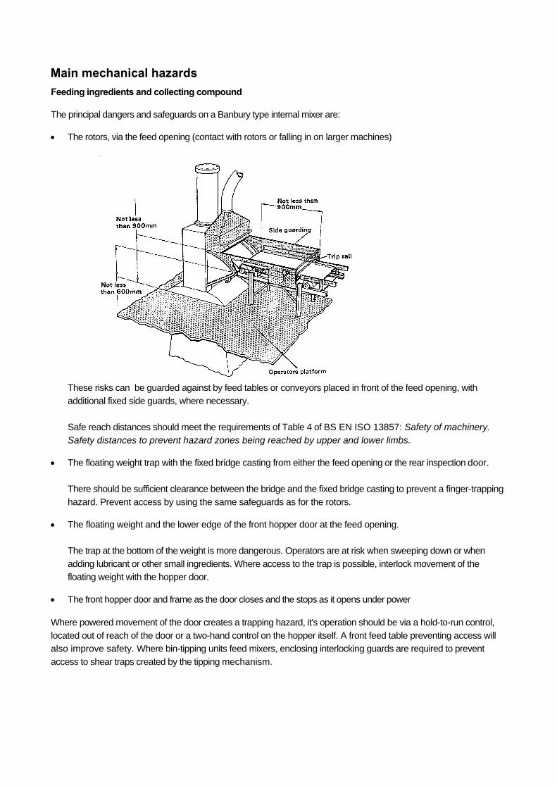
Main mechanical hazards Feeding ingredients and collecting compound
The principal dangers and safeguards on a Banbury type internal mixer are:
The rotors, via the feed opening (contact with rotors or falling in on larger machines)
These risks can be guarded against by feed tables or conveyors placed in front of the feed opening, with
additional fixed side guards, where necessary.
Safe reach distances should meet the requirements of Table 4 of BS EN ISO 13857: Safety of machinery.
Safety distances to prevent hazard zones being reached by upper and lower limbs.
The floating weight trap with the fixed bridge casting from either the feed opening or the rear inspection door.
There should be sufficient clearance between the bridge and the fixed bridge casting to prevent a finger-trapping
hazard. Prevent access by using the same safeguards as for the rotors.
The floating weight and the lower edge of the front hopper door at the feed opening.
The trap at the bottom of the weight is more dangerous. Operators are at risk when sweeping down or when
adding lubricant or other small ingredients. Where access to the trap is possible, interlock movement of the
floating weight with the hopper door.
The front hopper door and frame as the door closes and the stops as it opens under power
Where powered movement of the door creates a trapping hazard, it's operation should be via a hold-to-run control,
located out of reach of the door or a two-hand control on the hopper itself. A front feed table preventing access will
also improve safety. Where bin-tipping units feed mixers, enclosing interlocking guards are required to prevent
access to shear traps created by the tipping mechanism.
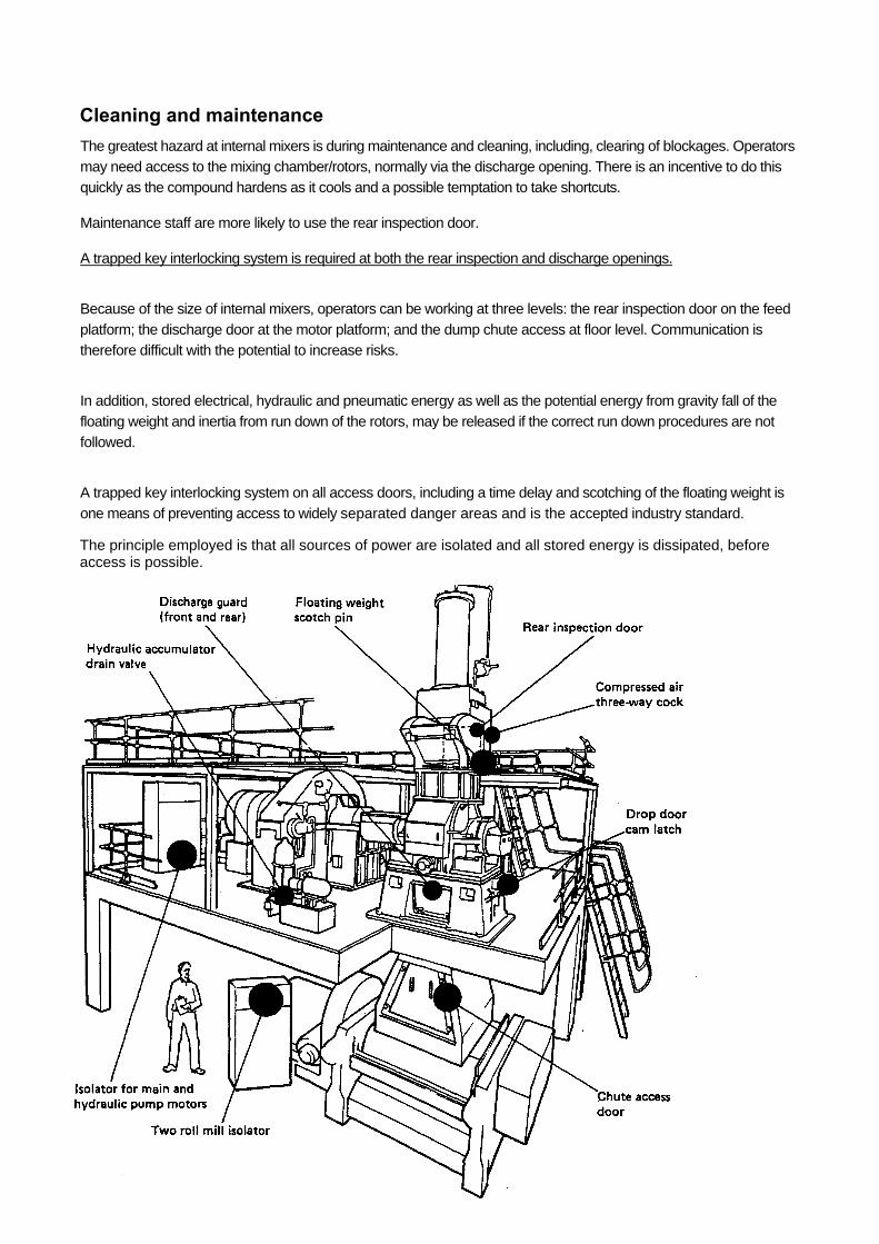
Cleaning and maintenance The greatest hazard at internal mixers is during maintenance and cleaning, including, clearing of blockages. Operators
may need access to the mixing chamber/rotors, normally via the discharge opening. There is an incentive to do this
quickly as the compound hardens as it cools and a possible temptation to take shortcuts.
Maintenance staff are more likely to use the rear inspection door.
A trapped key interlocking system is required at both the rear inspection and discharge openings.
Because of the size of internal mixers, operators can be working at three levels: the rear inspection door on the feed
platform; the discharge door at the motor platform; and the dump chute access at floor level. Communication is
therefore difficult with the potential to increase risks.
In addition, stored electrical, hydraulic and pneumatic energy as well as the potential energy from gravity fall of the
floating weight and inertia from run down of the rotors, may be released if the correct run down procedures are not
followed.
A trapped key interlocking system on all access doors, including a time delay and scotching of the floating weight is
one means of preventing access to widely separated danger areas and is the accepted industry standard.
The principle employed is that all sources of power are isolated and all stored energy is dissipated, before access is possible.
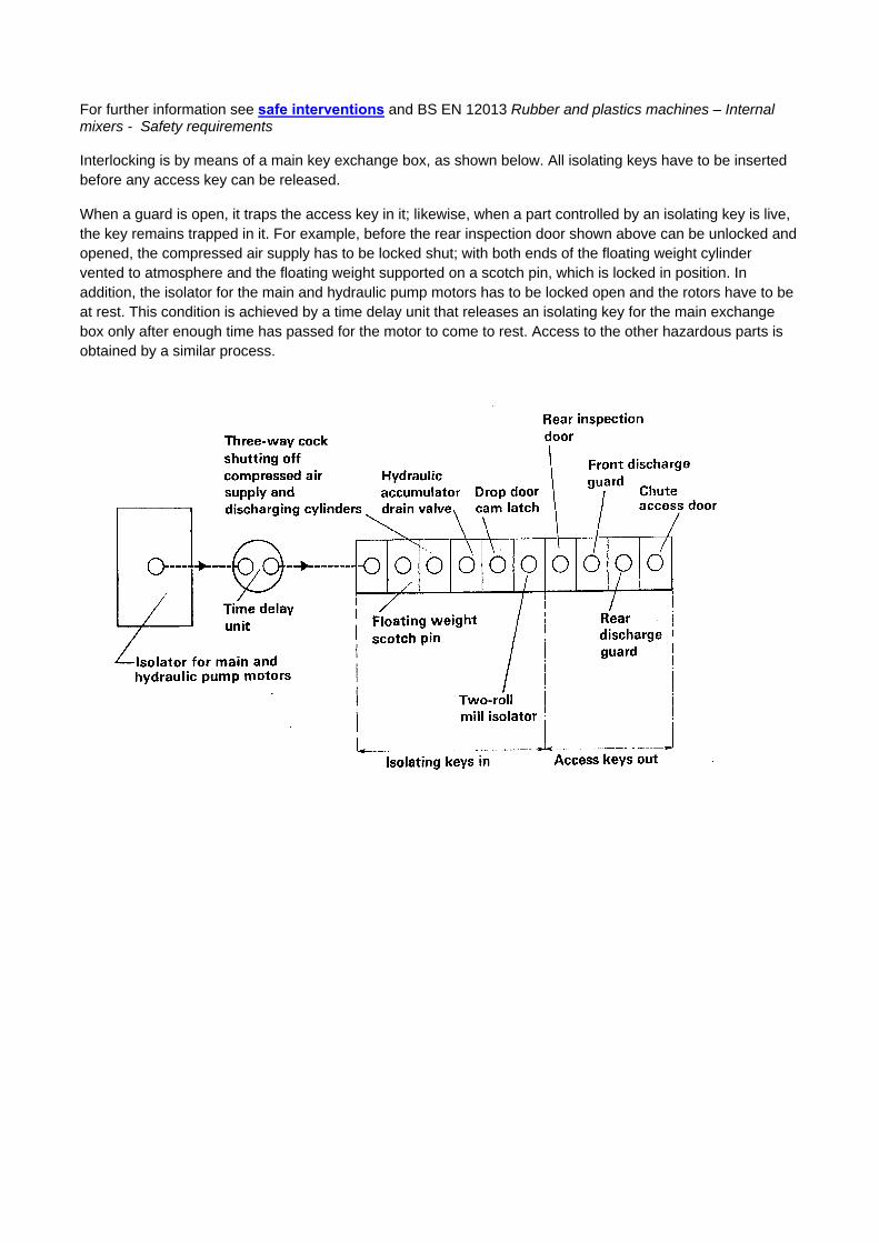
For further information see safe interventions and BS EN 12013 Rubber and plastics machines – Internal mixers - Safety requirements Interlocking is by means of a main key exchange box, as shown below. All isolating keys have to be inserted before any access key can be released.
When a guard is open, it traps the access key in it; likewise, when a part controlled by an isolating key is live, the key remains trapped in it. For example, before the rear inspection door shown above can be unlocked and opened, the compressed air supply has to be locked shut; with both ends of the floating weight cylinder vented to atmosphere and the floating weight supported on a scotch pin, which is locked in position. In addition, the isolator for the main and hydraulic pump motors has to be locked open and the rotors have to be at rest. This condition is achieved by a time delay unit that releases an isolating key for the main exchange box only after enough time has passed for the motor to come to rest. Access to the other hazardous parts is obtained by a similar process.
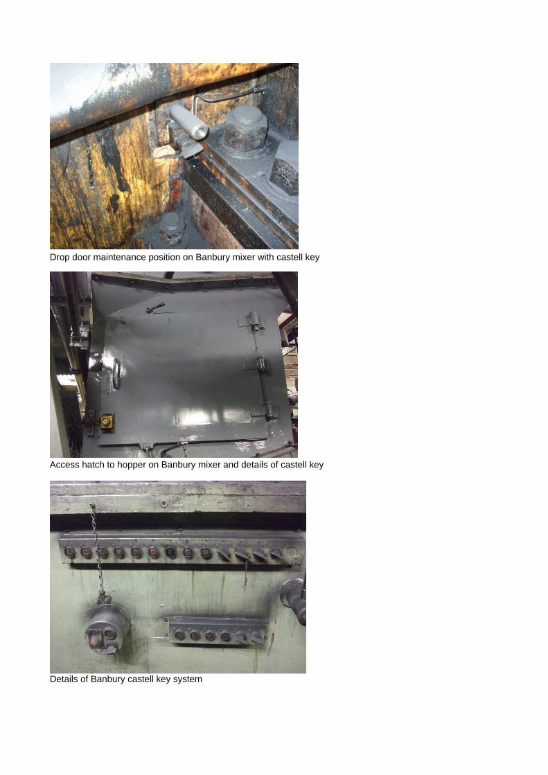
Drop door maintenance position on Banbury mixer with castell key
Access hatch to hopper on Banbury mixer and details of castell key
Details of Banbury castell key system
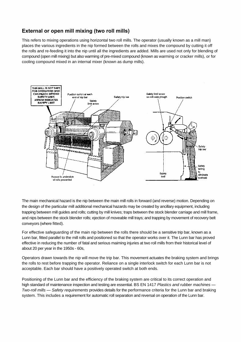
External or open mill mixing (two roll mills) This refers to mixing operations using horizontal two roll mills. The operator (usually known as a mill man) places the various ingredients in the nip formed between the rolls and mixes the compound by cutting it off the rolls and re-feeding it into the nip until all the ingredients are added. Mills are used not only for blending of compound (open mill mixing) but also warming of pre-mixed compound (known as warming or cracker mills), or for cooling compound mixed in an internal mixer (known as dump mills).
The main mechanical hazard is the nip between the main mill rolls in forward (and reverse) motion. Depending on
the design of the particular mill additional mechanical hazards may be created by ancillary equipment, including
trapping between mill guides and rolls; cutting by mill knives; traps between the stock blender carriage and mill frame,
and nips between the stock blender rolls; ejection of moveable mill trays; and trapping by movement of recovery belt
conveyors (where fitted).
For effective safeguarding of the main nip between the rolls there should be a sensitive trip bar, known as a Lunn bar, fitted parallel to the mill rolls and positioned so that the operator works over it. The Lunn bar has proved effective in reducing the number of fatal and serious maiming injuries at two roll mills from their historical level of about 20 per year in the 1950s - 60s,
Operators drawn towards the nip will move the trip bar. This movement actuates the braking system and brings the rolls to rest before trapping the operator. Reliance on a single interlock switch for each Lunn bar is not acceptable. Each bar should have a positively operated switch at both ends. Positioning of the Lunn bar and the efficiency of the braking system are critical to its correct operation and high standard of maintenance inspection and testing are essential. BS EN 1417 Plastics and rubber machines — Two-roll mills — Safety requirements provides details for the performance criteria for the Lunn bar and braking system. This includes a requirement for automatic roll separation and reversal on operation of the Lunn bar.
Extrusion
Introduction
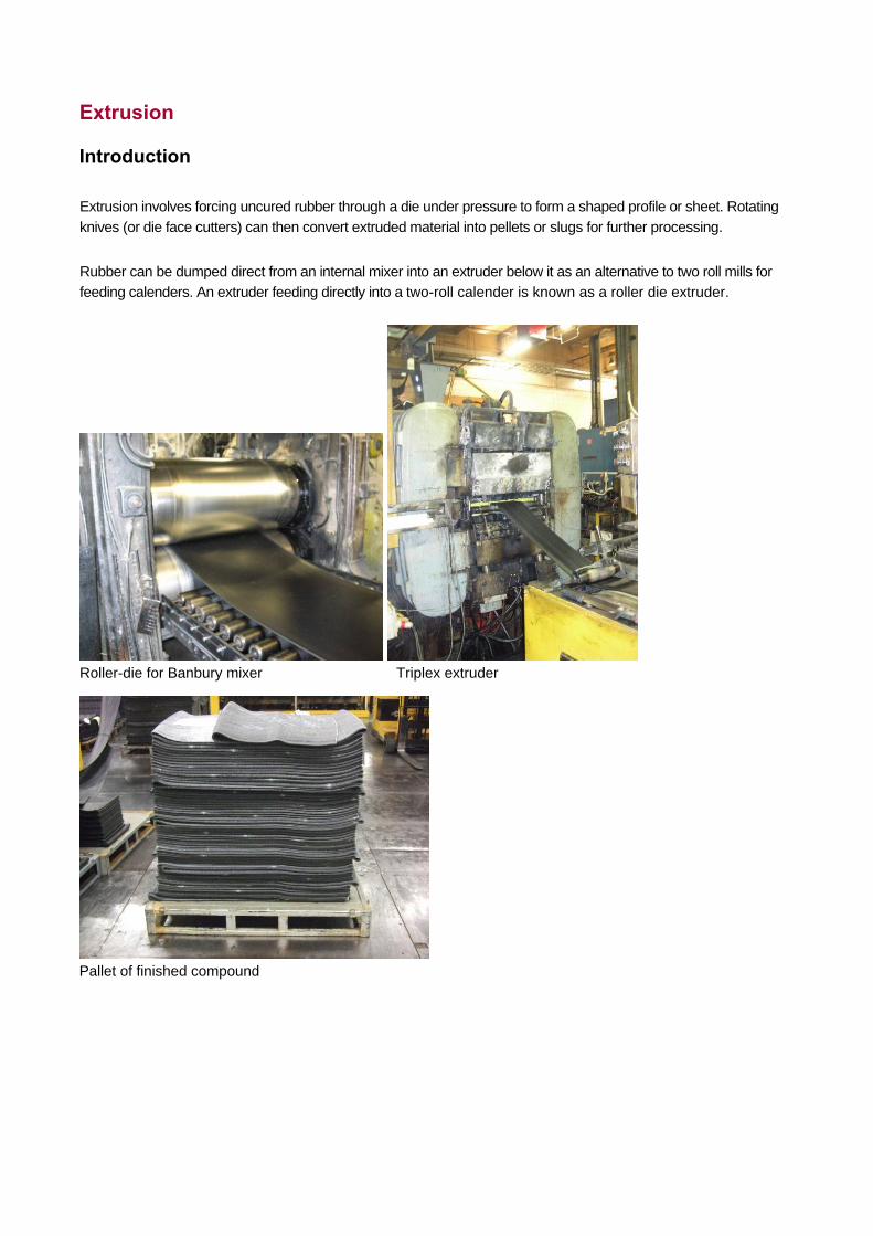
Extrusion involves forcing uncured rubber through a die under pressure to form a shaped profile or sheet. Rotating
knives (or die face cutters) can then convert extruded material into pellets or slugs for further processing.
Rubber can be dumped direct from an internal mixer into an extruder below it as an alternative to two roll mills for
feeding calenders. An extruder feeding directly into a two-roll calender is known as a roller die extruder.
Roller-die for Banbury mixer Triplex extruder
Pallet of finished compound
Mechanical hazards Screw (or scroll) extruders These machines convey uncured rubber forwards down the barrel and through the die by the action of a rotating
screw. They produce continuous extruded sections such as cable covering. Single screw versions are most common but twin or triple screw extruders may be used for complex products such as cable sheathing where they may be several layers of compound (co-extrusion).
Screw extruders can be either hot fed, with warmed pre-mixed rubber, or cold fed. Temperature control is generally by water circulating in a jacket around the extruder barrel, screw and die head. The rubber is normally fed in strip form, taken off a two-roll mill.
The main mechanical hazard on a single screw rubber extruder is the trap between the rotating screw and the fixed parts of the machine at the feed opening. Feed systems can also create additional trapping hazards such as a crammer feed device.
Where rubber is fed in strip form, feed rollers are often used to guide the strip into the feed opening. These may be free running, or driven in contra- rotating directions so that the strip remains under constant tension. Crammer feeding with an additional secondary screw is also common.
Use adequate fixed or interlocking guards to prevent access to the screw and other dangerous parts, whatever the feeding arrangement. The simplest arrangement is a series of free running rollers to guide the rubber strip. These must be spaced to prevent finger access to the screw. Where hinged feed hoppers or feeding devices are used these should be positively interlocked with movement of the screw.
Where powered movement of screen plates (perforated plates which 'strain out' contaminants) create a hazard, additional guarding may be required. The die breaking or being ejected is also a potential hazard. Although not common it occasionally occurs on machines with interchangeable dies where the die or die securing device is worn or inadequate. Regular inspection and maintenance are important.
For further information on screw extruders see BS EN 1114. Part 1 covers the extruder, Part 2 die face pelletizers, and Part 3 haul-off devices.
Haul-off units
A lot of reported injuries at extrusion lines occur at haul-offs downstream. These draw off the extruded profile continuously to be cured or cooled, and cut to length or reeled up. They operate by pulling the profile by means of friction between the product and two counter-rotating tracks, belts, or rollers set one above the other. Trapping hazards typically occur between the tracks at the feed position; between the extruded profile and the tracks; and between the drive pulleys and tension rollers, and the tracks.
When assessing the risk consider:
the speed of movement;
the forces and pressure applied (including the rigidity of the tracks and the profile); and
the method of operation.
Use of fixed or interlocking guards should be possible in most cases but guarding of the feed intake may not be so
easy because of the need to allow for different size profiles. The feed opening in the guard should provide adequate
protection for the largest profile handled. Tunnel guards profiled around the sides of the tracks at the feed intake, and
mounted on the top and bottom tracks may therefore be a better option. Use of free-running horizontal guide rollers in
front of the feed opening will further restrict access.
Feeding of product during start-up usually presents the greatest risk to the operator. Where there is a significant
trapping hazard, automatic feeding devices should be used, or feeding should be done with the haul-off stationary.
Where this is not possible a safe system of work is essential. Operate the haul-off at reduced speed, via a hold-to-run
control, which should be under the direct control of the operator. BS EN 1114. Part 3 permits a maximum feeding
speed of 200mm/second under these circumstances and gives details of more guarding options.
Ram extruders Here, a roll of rubber compound or 'pig' is placed into the extruder barrel with the die swung out of position; the die is then closed, either manually or under power, and the rubber is forced through the die by the forward action of a powered ram. The most common type is the Barwell extruder.
Because the extruder is loaded with individual batches of rubber, these machines cannot produce continuous profiles but produce a strip or pellet for further processing. Where pellets or slugs are produced, the die may have a rotating knife (die face cutter).
The main mechanical hazard is the trap between the closing die and the barrel on machines where there is power assisted die closure. Accidents have occurred when a second member of the extrusion team has attempted to assist die closure by trimming back the rubber during closure.
Die closure should be under two hand control and safe systems of work adopted to exclude third parties. Interlock movement of the ram with the die, so that ram movement is not possible with the die swung out of position. Rotating knives of die face cutters should have an interlocking guard with appropriate time delay to account for run down.
Calendering
Introduction
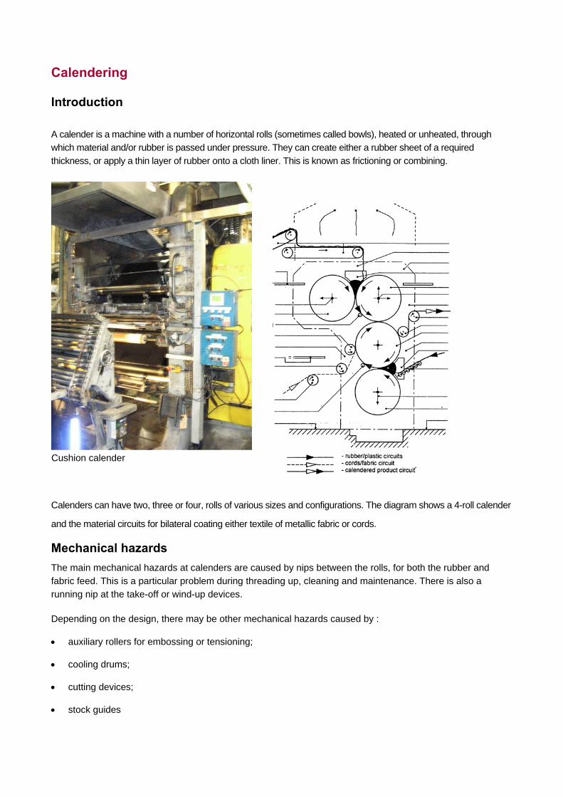
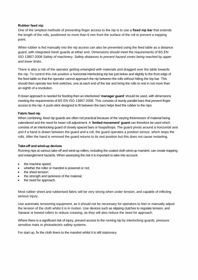
A calender is a machine with a number of horizontal rolls (sometimes called bowls), heated or unheated, through
which material and/or rubber is passed under pressure. They can create either a rubber sheet of a required
thickness, or apply a thin layer of rubber onto a cloth liner. This is known as frictioning or combining.
Cushion calender
Calenders can have two, three or four, rolls of various sizes and configurations. The diagram shows a 4-roll calender
and the material circuits for bilateral coating either textile of metallic fabric or cords.
Mechanical hazards The main mechanical hazards at calenders are caused by nips between the rolls, for both the rubber and
fabric feed. This is a particular problem during threading up, cleaning and maintenance. There is also a running nip at the take-off or wind-up devices.
Depending on the design, there may be other mechanical hazards caused by :
auxiliary rollers for embossing or tensioning;
cooling drums;
cutting devices;
stock guides
Rubber feed nip One of the simplest methods of preventing finger access to the nip is to use a fixed nip bar that extends
the length of the rolls, positioned no more than 6 mm from the surface of the roll to prevent a trapping
point.
When rubber is fed manually into the nip access can also be prevented using the feed table as a distance
guard, with integrated mesh guards at either end. Dimensions should meet the requirements of BS EN
ISO 13857:2008 Safety of machinery. Safety distances to prevent hazard zones being reached by upper
and lower limbs.
There is also a risk of the operator getting entangled with materials and dragged over the table towards
the nip. To control this risk position a horizontal interlocking trip bar just below and slightly to the front edge of
the feed table so that the operator cannot approach the nip between the rolls without hitting the trip bar. This
should then operate two limit switches, one at each end of the bar and bring the rolls to rest in not more than
an eighth of a revolution.
If closer approach is needed for feeding then an interlocked ‘manager guard’ should be used, with dimensions
meeting the requirements of BS EN ISO 13857:2008. This consists of sturdy parallel bars that prevent finger
access to the nip. A push-stick designed to fit between the bars helps feed the rubber to the nips.
Fabric feed nip When combining, fixed nip guards are often not practical because of the varying thicknesses of material being
calendered and the need for lower roll adjustment. A ‘limited movement’ guard can therefore be used which consists of an interlocking guard of closely spaced bars or hoops/loops. The guard pivots around a horizontal axis and if a hand is drawn between the guard and a roll, the guard operates a position sensor, which stops the
rolls. After the hand is removed the guard returns to its rest position but this does not cause restarting.
Take-off and wind-up devices Running nips at various take-off and wind-up rollers, including the coated cloth wind-up mandrel, can create trapping and entanglement hazards. When assessing the risk it is important to take into account: the machine speed; whether the roller or mandrel is powered or not; the sheet tension; the strength and tackiness of the material; the need for approach.
Most rubber sheet and rubberised fabric will be very strong when under tension, and capable of inflicting serious injury.
Use automatic tensioning equipment, as it should not be necessary for operators to feel or manually adjust the tension of the cloth whilst it is in motion. Use devices such as slipping clutches to regulate tension, and 'banana' or bowed rollers to reduce creasing, as they will also reduce the need for approach.
Where there is a significant risk of injury, prevent access to the running nip by interlocking guards, pressure sensitive mats or photoelectric safety systems.
For start up, fix the cloth liners to the mandrel whilst it is still stationary.
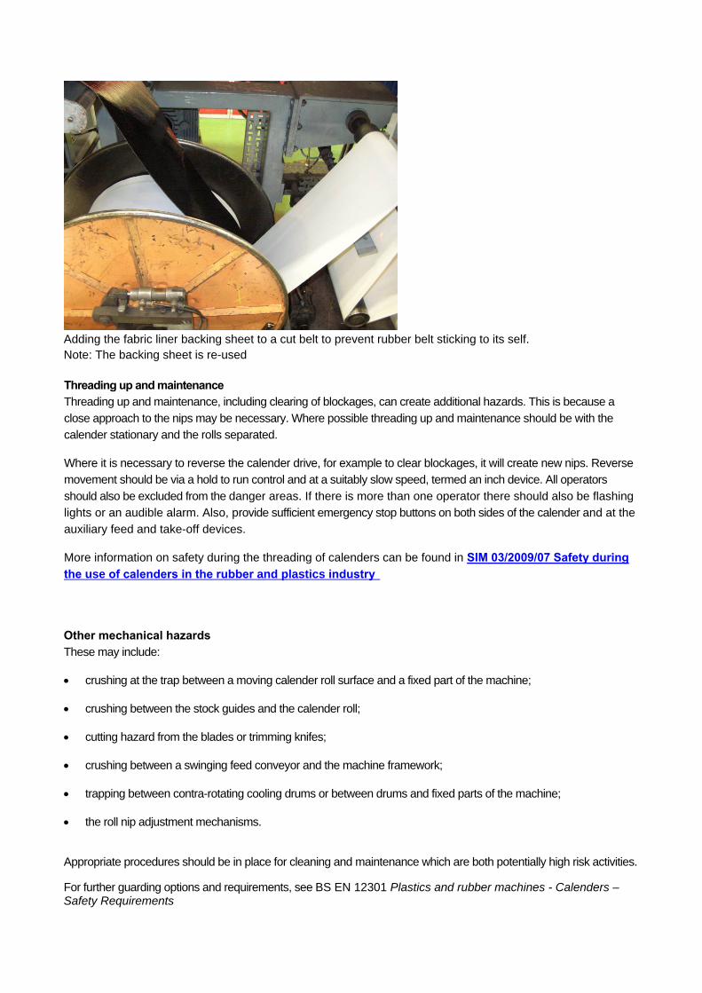
Adding the fabric liner backing sheet to a cut belt to prevent rubber belt sticking to its self. Note: The backing sheet is re-used
Threading up and maintenance Threading up and maintenance, including clearing of blockages, can create additional hazards. This is because a
close approach to the nips may be necessary. Where possible threading up and maintenance should be with the
calender stationary and the rolls separated.
Where it is necessary to reverse the calender drive, for example to clear blockages, it will create new nips. Reverse
movement should be via a hold to run control and at a suitably slow speed, termed an inch device. All operators
should also be excluded from the danger areas. If there is more than one operator there should also be flashing
lights or an audible alarm. Also, provide sufficient emergency stop buttons on both sides of the calender and at the
auxiliary feed and take-off devices.
More information on safety during the threading of calenders can be found in SIM 03/2009/07 Safety during the use of calenders in the rubber and plastics industry
Other mechanical hazards These may include:
crushing at the trap between a moving calender roll surface and a fixed part of the machine;
crushing between the stock guides and the calender roll;
cutting hazard from the blades or trimming knifes;
crushing between a swinging feed conveyor and the machine framework;
trapping between contra-rotating cooling drums or between drums and fixed parts of the machine;
the roll nip adjustment mechanisms.
Appropriate procedures should be in place for cleaning and maintenance which are both potentially high risk activities.
For further guarding options and requirements, see BS EN 12301 Plastics and rubber machines - Calenders – Safety Requirements
Cloth coating
Introduction Cloth coating involves the impregnation of cloth, mostly synthetic rather than cotton, with a rubber solution to produce a waterproof or chemically resistant fabric for use in waterproof clothing, tarpaulins, sails, dinghy fabrics etc. A range of rubbers and organic solvents are used to produce the rubber solution or 'dough'. Natural rubber, synthetic polymers such as chlorosulphonated polythene (Hypalon) and urethanes are the most widely used rubbers. Commonly used organic solvents include toluene, xylene, acetone, MEK, and petroleum naphtha blends (n-hexane based) SBPs 1-5.
Rubber compound, produced by internal or open mill mixing, is soaked in solvent before mixing to a solution with the consistency of light dough. Colours, other additives and more solvent may be added during mixing.
Some fabrics such as nylon require pre-treatment to achieve a good bond with the rubber. MDI is most widely used as a pre-dip, prior to the spreading process. Most fabrics are pre-dried, usually in a hot air oven, prior to coating.
Spreading machines evenly distribute the rubber solution onto the cloth as it is drawn under it, using an adjustable blade, known as a doctor blade. The coated fabric is then drawn into a drying oven to evaporate the solvent. The cloth is then passed over cooling rolls and wound up, either at the front or back of the machine. Embossing rollers positioned after the oven produce the desired surface finish. The process is usually repeated a number of times to achieve the required degree of proofing; the coating thickness at each pass is controlled by adjusting the height of the doctor blade.
The rubber solution is fed onto the cloth via a trough or tray. Solutions that are more viscous are added as a 'roll' of material directly onto the cloth and adjacent to the doctor blade. The speed of coating machines can vary considerably, from less than 10 metres per minute to over 100 metres per minute. The slower, usually older, spreaders often have steam-heated chests to drive off the solvent. High speed machines tend to use indirect gas-fired evaporating ovens.
The coated cloth can be vulcanised by either continuous curing, eg Rotocure, or more commonly by dusting the coated cloth with a starch based agent to prevent sticking and then re-rolling it and curing it in batches in a steam autoclave.
Mechanical and other hazards The risk of entanglement and shear trapping hazards at dough mixers should be controlled by having interlocking lids, and/or interlocking enclosing guards.
As many of the solvents are highly flammable suitably protected electrical devices are required. Also, control the risk from static charges. Precautions at evaporating ovens should include explosion relief and flame failure devices
Spreading machines can have nip and running nip hazards, particularly at the cloth wind-up, embossing, and cooling rollers. Higher production speeds will increase the risk and fixed or interlocking guards or other protective devices will be required. At slower speeds and for inaccessible nips, trip wires fitted to emergency stops may be acceptable, if justified in the risk assessment.
Safeguarding may also be required for any running nips when the cloth is re-rolled after curing.
Fabrication (including tank lining, roller covering and hose winding) Fabrication covers a range of operations where rubber and other materials are assembled to produce finished articles or components. Rubber lining operations and hose building present particular hazards.
Rubber lining operations
Rubber sheet may be bonded to metal components including valves, pipes, tanks, and rollers, and then vulcanised to provide a tough, corrosion resistant lining or covering. The main hazards common to all rubber lining operations are the health and fire hazards associated with the use of solvents for degreasing metal components and solvent-based bonding agents. Tank lining and roller covering have additional hazards.
Tank lining Rubber lining of tanks or other enclosed structures can be either in a factory or on site, but in either case usually involves the following operations:
Clean out the vessel (usually by steam);
Prepare the vessel surface (usually by shot blasting);
Apply rubber solution, or bonding agent (usually toluene or n-hexane based);
Place sheets of rubber in position (sometimes pre-warmed);
Vulcanise (using hot water or steam).
These operations present a number of significant hazards, including those associated with entry into confined spaces; shot blasting; use of flammable and/or toxic solvents; and use of pressure vessels.
For any work involving entry into confined spaces, strictly controlled safe operating procedures and high standards of operator training are essential. Detailed guidance can be found in the Safe work in confined spaces Approved Code of Practice, Regulations and guidance (L101) and Safe work in confined spaces Leaflet INDG258.
Breathing apparatus will protect the operator against the health hazard associated with solvent use but a fire and explosion hazard may remain. Therefore, use a non-flammable solvent wherever possible. Forced ventilation should reduce the concentration of flammable vapours in air to below one quarter of its lower explosive limit. If you can not do this then all potential ignition sources should be excluded and specially protected hand lamps used. Equipment should also be earthed.
Small rubber-lined articles are usually cured in an autoclave. Larger tanks or vessels may be converted into temporary steam receivers by blanking-off the entry point and admitting steam up to 20psi. The requirements of the Pressure Systems Regulations will then apply. Establish the vessels' safe operating limits and fit protective devices to protect against and warn of system failure.
Roller covering
Steel rollers are covered with rubber or polyurethane sheet as this will provide them with a controlled measure of resilience. They are then cured in autoclaves. In addition to health risks, there is also a danger of fire from the solvents and explosion from the fine cured rubber dust produced when grinding the covered roller to size.
The majority of reported fires in rubber factories involve finely divided vulcanised rubber and dust. Extraction at rubber grinding machines, depending on the particle size, will generally need to be designed and installed for use with potentially explosive dusts. Consider where the dust collection unit is located and in particular where explosion relief vents to. Good housekeeping will minimise the risks of a secondary dust explosion. If the operator attempts to take too deep a cut, it will cause the rubber to overheat and increase the fire risk.
For more information see Safe handling of combustible dusts: Precautions against explosions (HSG103) and SIM 03/2009/08 Hazardous area classification for explosible dusts in the rubber and plastics industries
Hose winding Introduction
Rubber hose has a wide variety of applications such as car parts for power steering, air conditioning systems, etc. The most common types are Nitrile and EPDM rubbers but silicones and flouroelastomers are more suited to high temperature applications.
The basic equipment used to produce hose consists of a metal mandrel supported in rotating chucks, one of which is driven. Standard metal working lathes are commonly used. To build up a hose, layers of rubber strip and fabric, with wire or rope used as reinforcing material, are wound onto the mandrel. The wire or rope is applied under tension. The final winding operation involves the application under slight tension of nylon webbing known as a spurle. The complete hose assembly on the mandrel is transferred to an autoclave for vulcanising. The cured hose is removed from the autoclave, put back in the machine, and the spurle unwound by reversing the direction of the headstock – this is known de-poling.
Light hose of small diameter is built up gradually by hand feeding materials along the length of the rotating mandrel. Heavy-duty hose is produced via a powered feed system, which automatically traverses along and in front of the rotating mandrel.
Mechanical hazards
The rotating mandrel and the fed material present a significant entanglement hazard. These have caused serious injuries to operators, particularly when wire and rope are used. There is also a running nip between the material and the mandrel. Operators should always wear close fitting clothing with cuffed or short sleeves, and tie back long hair.
These machines are extremely difficult to safeguard and specialist help may be needed when devising solutions.
For very short lengths of hose i.e. less than three metres, one option is to provide a hinged guard of horizontal bars, interlocked with a DC injection braking system, along the length of the mandrel and through which the various materials are fed. On machines where conventional guarding cannot be used the severity of an injury can be reduced by having a supported trip wire mounted above floor level, preferably so that the operator works over it , interlocked with a DC injection brake, combined with a monitored photoelectric safety device positioned above the mandrel.
On very long mandrels there may be significant deflection so photoelectric devices may not be an option. A combination of other safety devices should be used such as trip wires, foot operated emergency stop controls and hold-to-run controls.
When producing wire reinforced hose, it has been common practice for operators (wearing a leather waistcoat and leather gloves) to pass the wire around their back and through their gloved hand before feeding it onto the mandrel. This allows them to control the tension in the wire by leaning away from the mandrel but significantly increases the risk of entanglement. An alternative method for feeding the wire should be used, such as a trolley-mounted reel or an automatic winding head, which traverses the length of the machine.
If pressure testing is essential, it should be in a separate test facility capable of withstanding the effects of sudden energy release if a hose fails.
Vulcanisation (including presses, autoclaves and continuous vulcanisation)
Moulding Introduction
All vulcanising methods can cause burns. Insulate hot machine surfaces to prevent accidental contact where possible. Otherwise, warning signs and protective clothing (for lower arms as well as hands) are likely to be required.
Compression moulding
Compression moulding is the most common moulding technique used in the rubber industry. It involves pressing uncured rubber between heated moulds so that the rubber compound first fills the mould cavity before curing to produce the finished article. The presses are usually hydraulically or pneumatically powered and the moulds can be heated electrically, by steam, or by oil.
Compression moulding presses are generally vertical (the moving platen is raised or lowered in the vertical plane). The bottom platen can be up stroking or the top platen down stroking. Moulds may be fixed to both the platens, part fixed to a platen, or totally free to be drawn out of the press and loaded and unloaded on a press table. These loose moulds are usually charged (loaded) and stripped (unloaded) by hand. On fixed mould presses, mechanical devices, such as ejector pins or strippers will speed up the operation. This can reduce the need for close approach by the operator but can introduce additional trapping hazards.
When thin sheets such as car mats and gaskets, are being moulded it is possible to mould several items per press cycle by using several sets of moulds. Each mould is placed between platens in a multi-daylight press - the number of daylights is the number of spaces between the platens.
Transfer moulding
This is a variation on compression moulding and involves loading a pre-formed blank of rubber in a cavity connected to the mould cavity by a runner. The blank is compressed when the mould closes and is forced under pressure into the mould cavity. The safety considerations are the same as for compression moulding.
Injection moulding
This produces precision mouldings. The rubber is pre-heated and a rotating screw forces it into the mould cavity under pressure. Vertical injection moulding machines are more common than the horizontal type generally used in plastics processing.
Injection moulding machines can have a manual mode where the operator removes the moulded item at the end of each cycle. More common are semi-automatic or fully automatic machines where conveyor or pick and place robots remove the moulded product. Injection moulding machines tend to operate at faster speeds and on shorter cycle times than compression/transfer moulding, which effectively increases the potential risk to the operator from mechanical hazards.
Tyre curing presses
These are usually down-stroking machines, most often electrically or pneumatically powered. They have a rubber bladder, which is inflated into the tyre once it is in the mould and then filled with steam or high-pressure hot water to aid curing inside the tyre. Bursting or leaking bladders can cause serious scalds, particularly during press opening. Pressure sensitive switches should prevent opening when internal pressure is present.
For cross-ply tyres the moulds with the tread pattern are usually in two pieces (top and bottom).
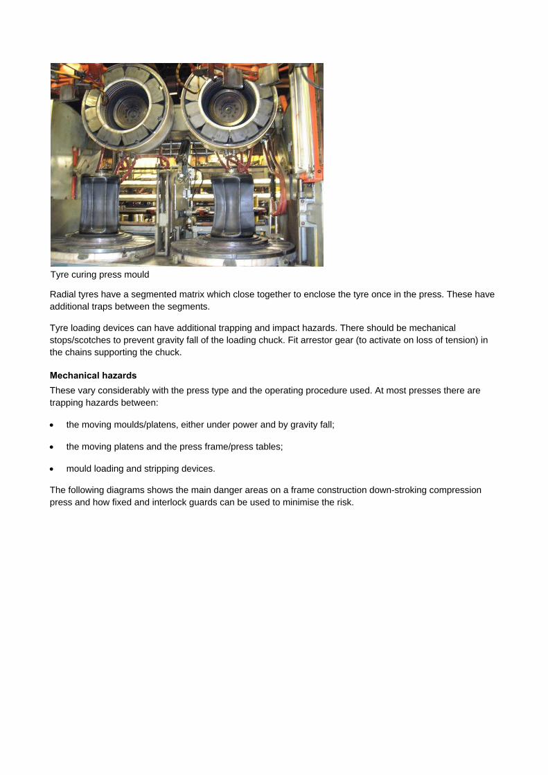
Tyre curing press mould
Radial tyres have a segmented matrix which close together to enclose the tyre once in the press. These have additional traps between the segments.
Tyre loading devices can have additional trapping and impact hazards. There should be mechanical stops/scotches to prevent gravity fall of the loading chuck. Fit arrestor gear (to activate on loss of tension) in the chains supporting the chuck.
Mechanical hazards These vary considerably with the press type and the operating procedure used. At most presses there are trapping hazards between:
the moving moulds/platens, either under power and by gravity fall;
the moving platens and the press frame/press tables;
mould loading and stripping devices.
The following diagrams shows the main danger areas on a frame construction down-stroking compression press and how fixed and interlock guards can be used to minimise the risk.
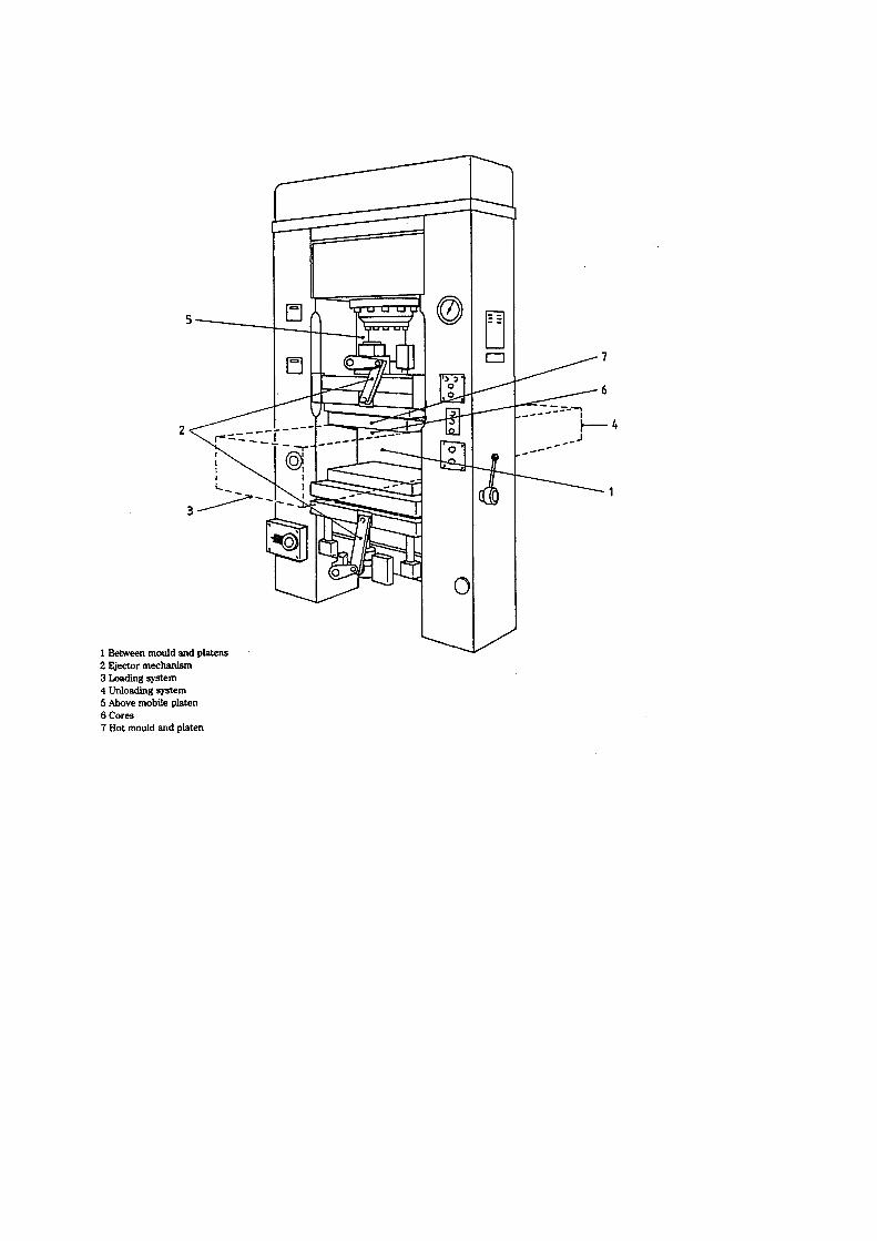
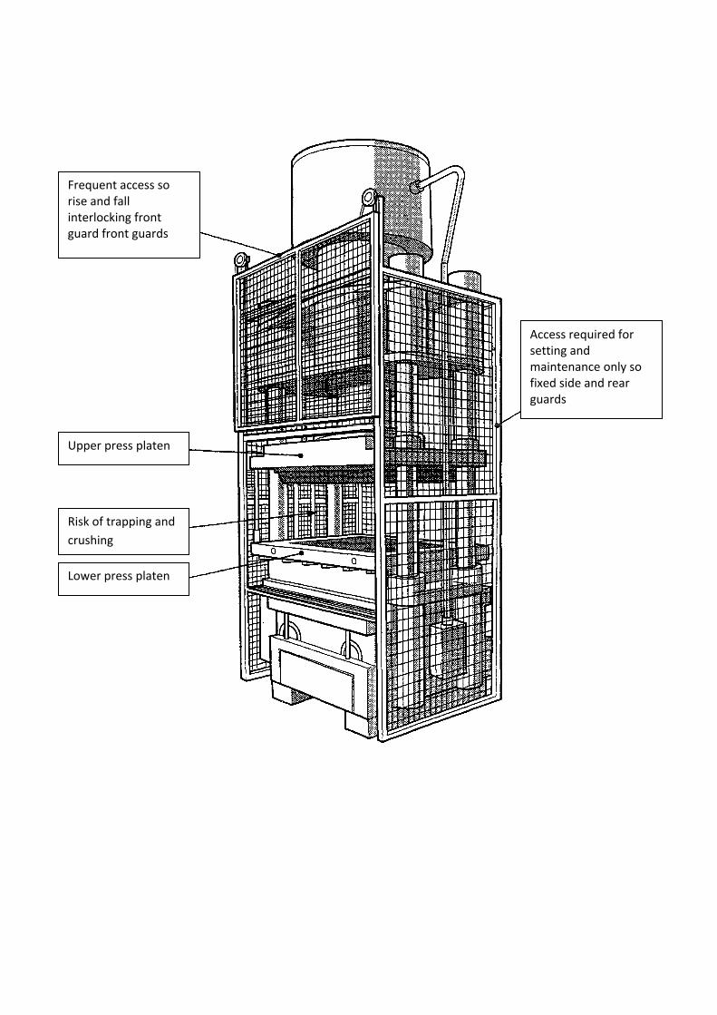
Access required for setting and maintenance only so fixed side and rear guards
Risk of trapping and
crushing
Upper press platen
Lower press platen
Frequent access so rise and fall interlocking front guard front guards
When assessing the risks and precautions needed, consideration should be given to:
the closing speed;
the number of moulds and amount of daylight;
whether up-stroking or down-stroking;
type of moulds (loose or fixed);
mode of operation, in particular, if worked at one or both sides and the number of operators;
the amount of body access between the moulds.
Many incidents happen during maintenance and tool changing and adequate controls against preventing falls due to
gravity are important for down-stroking presses. These could include scotching or having a pilot operated check
valve and counterbalance valve assembly in the hydraulic circuit.
For further information on guarding requirements see:
BS EN 289 Plastics and rubber machines — Presses — Safety requirements
BS EN 201 Plastics and rubber machines - Injection Moulding Machines
Autoclaves Introduction Autoclaves, known as 'curing pans' or 'vulcanisers', are pressure vessels filled with steam that are used to cure rubber articles not contained in moulds (hose, extruded section, coated cloth, retread tyres, and small cable batches). Most are horizontal with vertical autoclaves now rare. They can have either quick opening doors or multi-bolted doors.
Autoclaves have been involved in three fatalities since 2008. HSE have produced guidance on Safety requirement for autoclaves. This provides information on the safe operation and maintenance of these devices. It specifically addresses the risks associated with safeguarding, training and maintenance.
Continuous vulcanisation
Introduction Products produced on a continuous process such as rubber covered cable and strip are continuously cured, rather than on a batch basis. There are various methods but each one is sited just after the exit die of the extruder or calender.
Liquid salt baths These are usually gas-fired troughs of molten sodium and potassium nitrate mixtures. This method is particularly
suited for peroxide cured compounds, which must be cured in the absence of oxygen. The main hazard is fire and explosion associated with the use of molten salt at high temperature. Totally enclose salt baths as water in the molten salts could result in an explosive generation of steam. To prevent localised hot spots and overheating use
effective temperature control. There is a potential danger of splashing with hot salt when leading the extrudate through the salt bath and during maintenance and cleaning so suitable protective clothing, including full-face protection, should be worn.
Pressurised liquid salt continuous vulcanising (PLCV) Cable making often uses this process. It consists of a long gently slopping pressure chamber or tube fixed to the
extruder die. Vulcanising occurs by passing the cable through a molten mixture of salts in the pressurised chamber. The cured cable then passes through an enclosed water-cooled chamber to emerge cold at the end of the line. The main hazards associated with this process arise from the high temperatures and pressures involved. They include:
burns from accidental contact with the molten salt; fires from accidental mixing of salts with combustible materials;

an explosive reaction, involving generation of steam and an associated pressure rise caused by accidental mixing of hot salt and cold water.
Control the risks by having regular maintenance; correct operator training; and having the correct initial design. Interlocks are required between the salt and water pumps. Fit level controls to prevent water entering the molten salt
in the curing chamber. There should also be pressure relief before access into the chamber is possible. Suitable protective clothing is required for maintenance operations.
The pressurising medium is normally compressed air. The salt and water reservoirs are pressure vessels so subject to the requirements of the Safety of pressure systems. Pressure Systems Safety Regulations 2000. See the Safety of Pressure Systems (ACoP) - L122 for more information.
Other continuous vulcanisation processes
These include: rotocure - a system of heated drums over which the rubber is passed;
hot air or infra-red ovens; fluidised beds; microwave systems.
Microwave and infra-red curing ovens should be enclosed, with access doors interlocked with the electrical supply.
There may also be mechanical hazards on the following that will require safeguarding: conveyors;
rotocure rolls (nips); powered movement of oven/curing unit doors.
Latex processing
Introduction Latex is a dispersion of rubber particles in an aqueous phase. Most types of rubber, both natural and synthetic, can be made into a latex form. Latex gets used in specialised applications such as those requiring oil, solvent or flame resistance.
Different mixing techniques produce different grades of dispersions i.e. ball milling or ultrasonics for fine particle dispersions and simple stirring or colloid milling for coarse dispersions. Latex dipping is used to make thin articles such as gloves, balloons, condoms, catheters, bladders, hot water bottles etc and very fine particle dispersions are needed. Coarser particle sized dispersion (slurry) is acceptable for latex foam, used mainly for carpet backing.
The following range of additives can be mixed with the latex dispersion or emulsion:
Stabilisers, to maintain the rubber particles in a stable state of suspension. These include sulphonates, inorganic complex phosphates and soaps.
Curing agents, usually sulphur.
Accelerators, including dithiocarbamates, thiazoles, thiurams, and xanthates.
Thickeners, including casein, glue, cellulose derivatives.
Anti degradants - including waxes, substituted phenols, amine based antioxidants.
PH adjusters, including ammonia, sodium and potassium hydroxide, and formaldehyde.
Biocides, mostly halogen derivatives, for suppression of bacterial decay and fungal infection.
Coagulants and gelling agents, include calcium, magnesium and aluminium salts, acetic and formic acid, cyclohexylamine acetate and ammonium acetate.
Latex dipping and casting This uses a porcelain or aluminium mould (or former) that is repeatedly dipped in the latex compound. Once set, the coated former is washed, air-dried and vulcanised in steam autoclaves before the product is removed. To increase the thickness of the deposit obtained per dip, the former is immersed in coagulant before and after each latex dip.
Latex casting is a similar technique to dipping but is used to make hollow seamless articles. The product forms on the inside of the mould (in contrast to dipping) giving a better surface definition. This process is uncommon.
Mechanical hazards Latex mixing plant and processing equipment such as carpet backing machines, may present a range of mechanical hazards that will require effective safeguarding by the techniques described in previous sections. Autoclaves used for vulcanising latex articles will come within the Safety of pressure systems - Pressure Systems Safety Regulations 2000. See the Safety of Pressure Systems (ACoP) - L122 for more information. See also Safety requirement for autoclaves. This provides information on the safe operation and maintenance of these devices. It specifically addresses the risks associated with safeguarding, training and maintenance.
Polyurethanes (including PU foam production, re-constituted foam, foam conversion and rigid urethanes) Polyurethanes are used in a wide variety of forms ranging from coatings and lacquers to flexible foam. Polyurethane elastomers can be divided into either foamed or rigid urethanes. However, both are based on a common chemical reaction between a long chain alcohol (polyol) and an isocyanate. Urethanes with differing
physical and chemical properties are made by varying the type of polyol and/or isocyanate. Appropriate measures to control the health risk should be in place.
Polyurethane (PU) foam production Introduction
PU foam is produced by releasing gas into the reacting isocyanate and polyol so that when the reaction is complete the elastomeric material is formed around a network of fine gas bubbles. The process involves
metering the liquid isocyanate and polyol into a mixing head with other chemicals (blowing agents, catalysts and surfactants). The mixed reactants are poured onto a conveyor, into a mould, or sprayed in situ, and after a few minutes react to form elastomeric foam. Polyether polyols and toluene di-isocyanate (TDI) are most
commonly used in flexible foam production; diphenyl methane di-isocyanate (MDI) is most commonly used in rigid foam production.
The main blowing agent used is carbon dioxide, generated by the reaction between water and isocyanate.
Catalysts, commonly amines and tin salts, accelerate and control the rate of the water/isocyanate reaction. Surfactants assist the mixing of the components to form a homogenous liquid and stabilise the bubbles in the foam during expansion, so preventing collapse before the liquid face polymerises. In most cases the polyol,
catalysts, surfactants and water are supplied as a pre-mixed polyol blend, so that there are effectively only two components – the polyol blend and the isocyanate.
Flexible PU foam - block production
Production of continuous block is the method used by all the major producers of flexible PU foam. Metering pumps send the separate components into to a mixing head. In most cases the polyol blend and isocyanate are pumped directly from bulk storage tanks and metered individually into the mixing head under pressure.
The metering pumps need to be calibrated at regular intervals and this involves discharging individual materials from the mixing head into a receptacle that is then weighed.
After mixing they are deposited onto a moving paper-lined conveyor. As the conveyor carries the liquid mix
into the curing tunnel, the gas reaction causes the material to rise to an optimum height of about 1 to 1.5 metres at which time the urethane polymer sets rigid. The paper is then stripped off and the foam is cut to length by travelling band knives integral to the conveyor.
Cut blocks are conveyed to a storage area where they are left for up to four hours to mature. The exothermic reaction that produces the foam block will continue for several hours before the block is cured. This process is monitored by thermocouple.
Single block production requires much lower capital investment and is used by smaller foam converters. The plant required includes storage and metering facilities for the polyol blend and isocyanate, and a mould similar in shape to a domestic loaf tin. Polyol components are likely to be supplied pre-blended in 200 litre drums.
The main hazards associated with the process are identical to those at other continuous plant.
Moulded PU foam
Flexible and rigid PU foam is widely used in the production of shaped articles such as car/aircraft seats and cushions. Polyol pre-blends are metered and mixed with isocyanates, the same as in block production. The
mixed material is poured into a mould, a lid is fitted and the material left to rise and complete the reaction.
The moulding process can be either hot cure or cold cure moulding. Hot cure moulding applies heat to speed up the curing process. This requires considerable capital expenditure as curing ovens, conveyors up to 100
metres in length and steel moulds, capable of withstand the high temperatures, are required. Historically this type of moulding produces high volume components for the automotive industry.
Cold cure moulding uses less sophisticated metering equipment and fibreglass or wooden moulds. This type
of moulding is used in the upholstery industry.
A further development is reaction injection moulding. This process is similar to cold cure moulding but the polyol blends and isocyanates (in this case usually MDI) are metered and mixed under high pressure and
injected into a mould cavity.
In situ injection or spraying
Rigid PU foam is used for:
insulation purposes, eg freight containers, tanks, pipes and cold store vehicles; buoyancy, eg in lifeboats and canoes;
packaging; foam-cored panels.
MDI-based foam is sprayed or injected in situ, normally with portable dispensing equipment. Use of open
containers for mixing and pouring foam should be avoided and LEV will be needed where enclosed systems
cannot be used.
Fire hazard
Flexible PU foam, even combustion modified high resilience (CMHR) grades, is regarded as high fire hazard
materials in manufacturing and conversion premises, unless there is evidence to demonstrate otherwise. Fire precautions in the clothing and textile industries contains advice on how to assess the fire hazard of such materials. Certain very high density grades of PU foam, very expensive grades mainly used in aircraft
applications, have in tests been shown to present a lower, ie normal, fire hazard. Smoke from PU foam will contain highly toxic and irritant components including hydrogen cyanide and isocyanates, and a high standard of fire precautions is required.
For block production there should be fixed fire protection incorporated into the foaming machine. Bulk block stores should also be fire resisting. Regular checks should be made of the internal temperature of large blocks and written procedures developed to deal with an overheating block, eg transfer to a safe place
outside the building. Fires have occurred involving blocks that have not fully cured before being loaded onto vehicles, where the exothermic reaction continued. Further detailed advice on the precautions required to control the fire hazard is contained in Safe use and storage of cellular plastics (HSG92)
Mechanical hazards
Guard the trapping points at the mould closing and any between the fixed and moving parts of carousel
moulding machines. A further trap may exist between the injection nozzle and the mould in reaction injection
moulding. Apply the usual machinery guarding considerations.
Reconstituted foam Introduction
PU foam off-cuts can be reconstituted into ‘recon’ or ‘chip foam’. The process involves grinding the off-cuts into small pieces (crumb) in either a granulator or hammer mill. The crumb is sieved and transferred to a mixing hopper where it is sprayed with a polyurethane pre-polymer (partially reacted polyol and isocyanate mix). It is then transferred to a mould, compressed up to six times its original density, and cured by means of steam. After curing, the block is de-moulded and cooled.
Fire and explosion hazards
The production and use of PU foam crumb can give rise to a very high fire hazard unless the operations are strictly controlled. Crumb can spread and act as a fuse for the spread of fire. The dust and fine crumb produced in hammer mills and granulators can cause dust explosions. Controls include:
fire resisting separation; enclosure and ventilation control at crumbing plant;
good housekeeping; explosion relief on dust collection plant.
Further advice can be found in:
Safe use and storage of cellular plastics (HSG92) Safe handling of combustible dusts: Precautions against explosions (HSG103) SIM 03/2009/08 Hazardous area classification for explosible dusts in the rubber and plastics
industries
Mechanical and other hazards Hammer mills and granulators are often fed by conveyor and the feed openings should be dimensioned so that operator access to dangerous parts is prevented. Access doors into the granulator/mill should be positively interlocked with time delay/braked motors, where necessary, to account for rundown times.
Steam systems will be subject to the requirements of the Safety of pressure systems. Pressure Systems Safety Regulations 2000. See the Safety of Pressure Systems (ACoP) - L122 for more information.
High noise levels at granulators and hammer mills can be a problem so provide acoustic enclosures around the machines with interlocks where necessary to prevent access to dangerous parts. Otherwise, use localised acoustic cladding.
Foam conversion Introduction
Foam conversion involves cutting or shaping, and fabrication (gluing and assembly) of block foam or reconstituted foam into product components, for example, shaped cushions for upholstery. It also includes finished products such as synthetic sponges and floor mats. Fire hazards area a particular problem in cramped premises.
Cutting/shaping
PU foam blocks about 1.5m x 1.5m x 3m can be cut or shaped using a variety of band knives, slitters, automatic shapers and peelers. Hot wire cutting is now very rare.
Mechanical hazards
Foam cutting band knives and other slitting machines are difficult to safeguard effectively. Because of the size of the foam blocks large sections of blade may have to remain exposed. Accepted safeguarding standards in foam conversion differ from those found in other industries. This is because foam is much easier to handle than wood, meat or textiles and there is there is little risk of kickback or slipping. There are low numbers of reported injuries on PU foam band knives.
When assessing the risk and the safeguards required take account of the size, shape, range and throughput of the work, particularly the need for close approach. Consider also the type and age of the machine as well as the age and experience of the operator.
See BS EN 14886 Plastics and rubber machines – Band knife cutting machines for block foams – safety requirements for the specific safeguards required for each type of band knife.
There are a number of common requirements that apply to all types of band knives and slitters:
Blade handling and approach to the blade:
Blades are made from high quality steel welded to be continuous, with either a double-cutting edge for
reciprocal cutting or a single cutting edge with a rounded-off back. They are usually smooth, bevel-edged,
rather than toothed or serrated. Blades are normally supplied unsharpened but once sharpened they are
extremely hazardous, causing severe lacerations so wear chain mail gloves when handling sharpened
blades. Most serious accidents tend to occur during maintenance when the blade is stationary. To dispose of
blades safely pull them through the machine and snap into short pieces for safe disposal.
Wear a full chain mail glove on the hand closest to the blade when working close to a band knife (the hand
guiding the work). Also, use a jig and remote work holders if possible. Where there is only close approach for
the last piece of an otherwise large block, a section of foam can be used as a push stick.
Blade sharpening on smooth edged band knives is usually by a panel in the machine casing giving access to
a pair of small grinding wheels. When the operator needs to sharpen the blade there is a mechanism for
bringing these into contact with the blade. This is normally with the access door closed as a perspex panel
allows viewing. On older machines, this door may not be interlocked and where tool tight fastenings to keep it
closed is not strictly enforced, retrofitting of interlocks may be appropriate. If older machines have knurled
knobs or wing nut type fastenings, replace them with tool-tight fastenings.
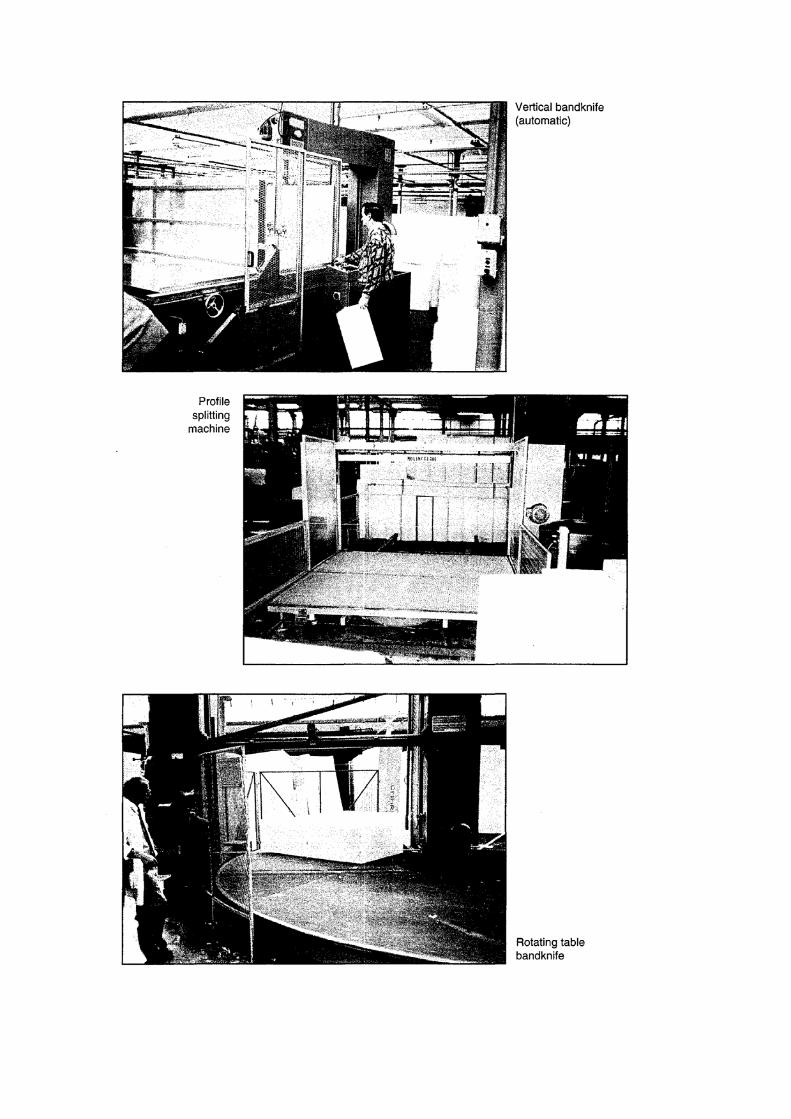
Vertical band knives:
These include true vertical knives, and inclined (or canting) band knives, where the knife frame can be tilted from the vertical. The most common type have a traversing horizontal table which supports the work piece; on
some very old machines the foam may be moved by hand on a fixed table.
Provide a strong manually or power adjusted guard enclosing the cutting edges of the band knife. Keep the
guard adjusted to just above the height of the work piece and lower it to the machine table when the machine
is not in use. See BS EN 14886 Plastics and rubber machines – Band knife cutting machines for block foams
– Safety requirements for specific guarding requirements to prevent the operator's hand and head contacting
the knife when cutting large blocks of foam.
No additional guarding at the other sides of the band knife table is required where the size of the table
prevents accidental contact with the blade from the operating position. On fully automatic band knives there is
no need for close approach by the operator during the cutting cycle. Provide sliding interlocking guards to
prevent access to the blade from the operating position, as shown in the diagram. Some fully automatic band
knives have a fixed table and a moving knife frame. Movement of the knife frame itself may create an
additional hazard so guard to prevent any access to traps between the frame at the limits of its travel and
surrounding plant.
Horizontal slitters:
These machines have the exposed part of the blade in the horizontal plane and the workpiece supported on either a
reciprocating table or a large conveyor belt, which can travel in both directions. In either case, provide safeguarding as specified in BS EN 14886. This should include a parking guard (usually L-shaped or U-shaped cover) to prevent accidental contact with the blade when the machine is not in use. On machines with a reciprocating table,
there may be a shear trap between the table at the limits of its travel and fixed parts or the structure of the building. If this is the case then a sensitive leading edge or pressure sensitive mat can be fitted, or distance fencing provided. Machines with conveyor belts should not have exposed traps between belts and end rollers.
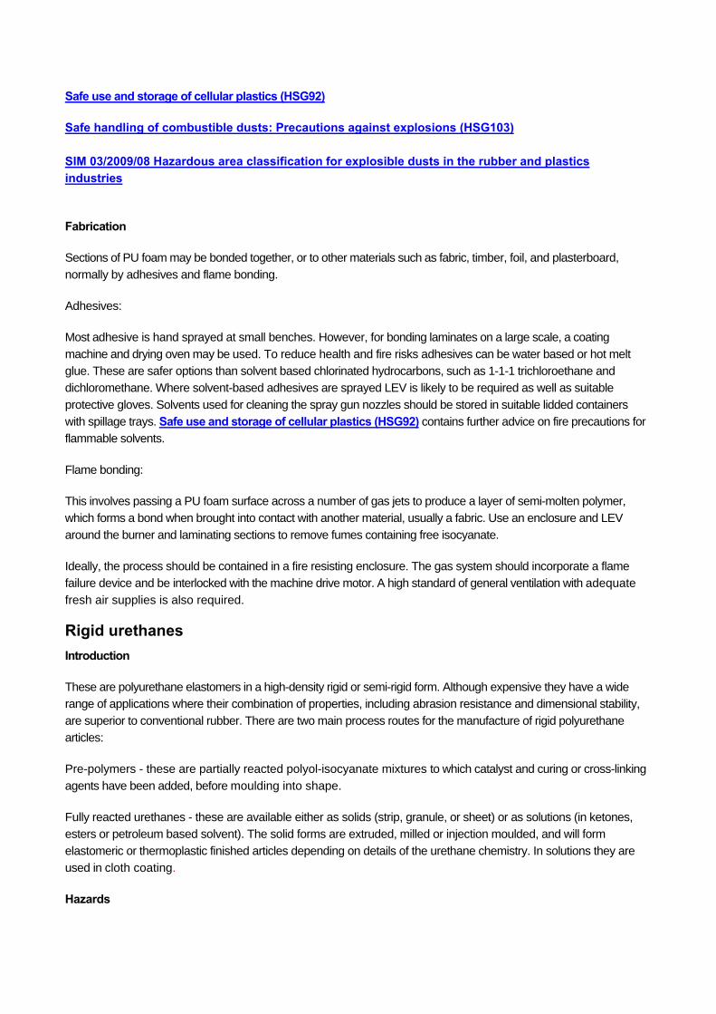
Rotary slitting machines (or rotating table band knives):
The blocks of foam are placed on a large rotating table and a fixed knife slices a section through the foam as the table rotates. The blade indexes down a set distance after each revolution, and repeats the process. The usual
standard of guarding found, particularly at older machines, is a series of trip wires around the perimeter of the machine, and/or partial fixed fencing adjacent to the blade (see diagram). Although these only provide a very basic level of protection, there should be no need for close approach once the machine is set up. Adequate training and
supervision of operators is important and regular testing of trip wires essential.
Newer machines complying with BS EN 14886 have fixed guards and a perimeter fencing all around the table, with interlocking access gates or electro-sensitive protective equipment – see standard for more details. A risk assessment
may justify improving older machines to this standard of safeguarding. As at slitters, provide a parking guard to cover the blade when not in use.
Horizontal profile splitting machines or automatic shapers:
These are similar to horizontal slitting machines, normally with a reciprocating table. Blade movement is programmed to follow a set contour to provide curved shapes. Safeguarding standards should be equivalent to those at horizontal slitters. These machines are often smaller than slitters and as a result access to the blade from the ends of the
machine table may be easier and additional perimeter guarding may be necessary (see diagram).
Foam peeling machines:
A cylinder of foam is mounted on a central shaft and the block rotates against a horizontal band knife. There should
be no need for close approach except for loading and unloading. Provide interlocking distance fencing at the cutting side of the knife and a cover to prevent accidental contact with the blade when not in use.
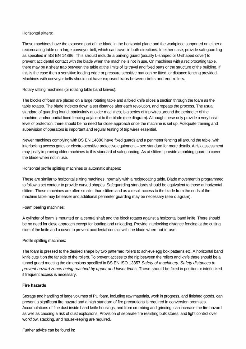
Profile splitting machines:
The foam is pressed to the desired shape by two patterned rollers to achieve egg box patterns etc. A horizontal band knife cuts it on the far side of the rollers. To prevent access to the nip between the rollers and knife there should be a tunnel guard meeting the dimensions specified in BS EN ISO 13857 Safety of machinery. Safety distances to
prevent hazard zones being reached by upper and lower limbs. These should be fixed in position or interlocked if frequent access is necessary.
Fire hazards
Storage and handling of large volumes of PU foam, including raw materials, work in progress, and finished goods, can present a significant fire hazard and a high standard of fire precautions is required in conversion premises. Accumulations of fine dust inside band knife housings, and from crumbing and grinding, can increase the fire hazard
as well as causing a risk of dust explosions. Provision of separate fire resisting bulk stores, and tight control over workflow, stacking, and housekeeping are required.
Further advice can be found in:
Safe use and storage of cellular plastics (HSG92)
Safe handling of combustible dusts: Precautions against explosions (HSG103)
SIM 03/2009/08 Hazardous area classification for explosible dusts in the rubber and plastics industries
Fabrication
Sections of PU foam may be bonded together, or to other materials such as fabric, timber, foil, and plasterboard,
normally by adhesives and flame bonding.
Adhesives:
Most adhesive is hand sprayed at small benches. However, for bonding laminates on a large scale, a coating
machine and drying oven may be used. To reduce health and fire risks adhesives can be water based or hot melt glue. These are safer options than solvent based chlorinated hydrocarbons, such as 1-1-1 trichloroethane and dichloromethane. Where solvent-based adhesives are sprayed LEV is likely to be required as well as suitable
protective gloves. Solvents used for cleaning the spray gun nozzles should be stored in suitable lidded containers with spillage trays. Safe use and storage of cellular plastics (HSG92) contains further advice on fire precautions for flammable solvents.
Flame bonding:
This involves passing a PU foam surface across a number of gas jets to produce a layer of semi-molten polymer, which forms a bond when brought into contact with another material, usually a fabric. Use an enclosure and LEV
around the burner and laminating sections to remove fumes containing free isocyanate.
Ideally, the process should be contained in a fire resisting enclosure. The gas system should incorporate a flame failure device and be interlocked with the machine drive motor. A high standard of general ventilation with adequate
fresh air supplies is also required.
Rigid urethanes Introduction
These are polyurethane elastomers in a high-density rigid or semi-rigid form. Although expensive they have a wide range of applications where their combination of properties, including abrasion resistance and dimensional stability,
are superior to conventional rubber. There are two main process routes for the manufacture of rigid polyurethane articles:
Pre-polymers - these are partially reacted polyol-isocyanate mixtures to which catalyst and curing or cross-linking
agents have been added, before moulding into shape.
Fully reacted urethanes - these are available either as solids (strip, granule, or sheet) or as solutions (in ketones, esters or petroleum based solvent). The solid forms are extruded, milled or injection moulded, and will form
elastomeric or thermoplastic finished articles depending on details of the urethane chemistry. In solutions they are used in cloth coating.
Hazards

Pre-polymers Isocyanate pre-polymers are often cross-linked by MbOCA to form polyurethane elastomers, which are then
moulded. For more information on MbOCA, see the health and safety topics page on HSE’s rubber website.
Fully reacted polyurethanes These usually contain negligible amounts of isocyanate as the reaction has gone to completion. If processed at high temperatures there can however be some isocyanate release. Many solutions contain highly flammable solvents, which will require the usual occupational hygiene and fire safety precautions including LEV.
Tyre building Note: The processes and associated hazards are only briefly covered in this section as they are covered in greater detail in: Compounding, Extrusion, Calendaring, Vulcanising and Tyre re-treading.
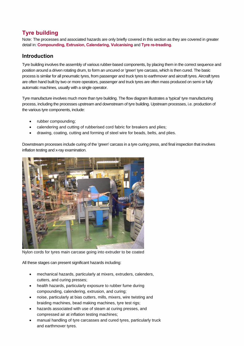
Introduction Tyre building involves the assembly of various rubber-based components, by placing them in the correct sequence and position around a driven rotating drum, to form an uncured or 'green' tyre carcass, which is then cured. The basic
process is similar for all pneumatic tyres, from passenger and truck tyres to earthmover and aircraft tyres. Aircraft tyres are often hand built by two or more operators, passenger and truck tyres are often mass produced on semi or fully automatic machines, usually with a single operator.
Tyre manufacture involves much more than tyre building. The flow diagram illustrates a 'typical' tyre manufacturing process, including the processes upstream and downstream of tyre building. Upstream processes, i.e. production of the various tyre components, include:
rubber compounding; calendering and cutting of rubberised cord fabric for breakers and plies;
drawing, coating, cutting and forming of steel wire for beads, belts, and plies.
Downstream processes include curing of the 'green' carcass in a tyre curing press, and final inspection that involves
inflation testing and x-ray examination.
Nylon cords for tyres main carcase going into extruder to be coated
All these stages can present significant hazards including:
mechanical hazards, particularly at mixers, extruders, calenders, cutters, and curing presses;
health hazards, particularly exposure to rubber fume during compounding, calendering, extrusion, and curing;
noise, particularly at bias cutters, mills, mixers, wire twisting and
braiding machines, bead making machines, tyre test rigs; hazards associated with use of steam at curing presses, and
compressed air at inflation testing machines;
manual handling of tyre carcasses and cured tyres, particularly truck and earthmover tyres.
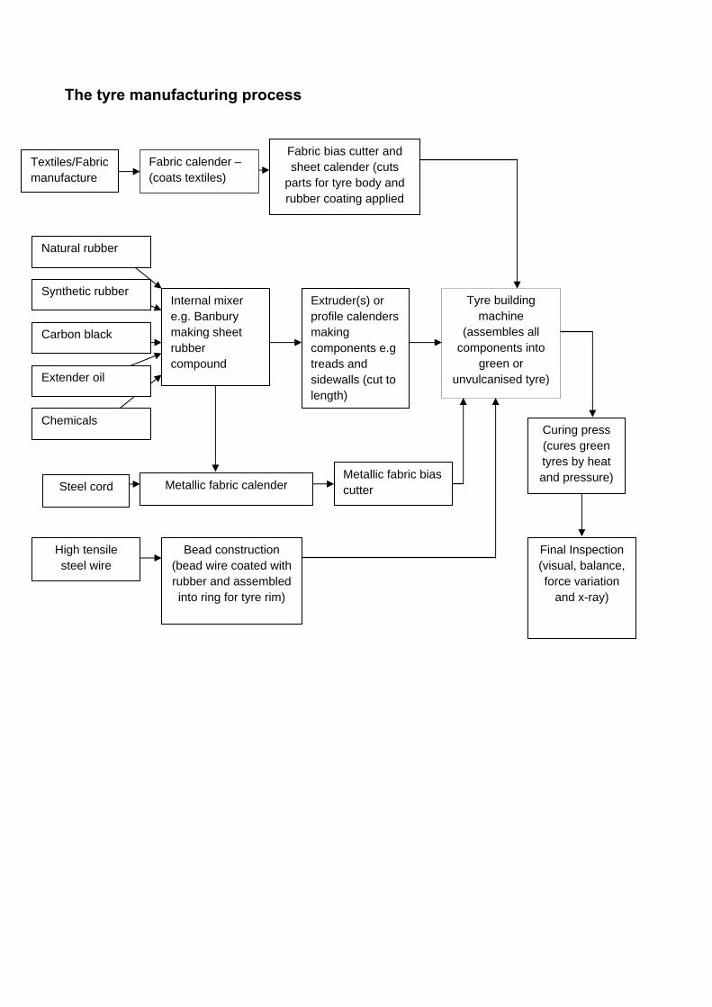
The tyre manufacturing process
Textiles/Fabric manufacture
Steel cord
Internal mixer e.g. Banbury making sheet rubber compound
Natural rubber
Tyre building machine
(assembles all components into
green or unvulcanised tyre)
Fabric calender – (coats textiles)
Fabric bias cutter and sheet calender (cuts
parts for tyre body and rubber coating applied
Extender oil
Chemicals
Carbon black
High tensile steel wire
Synthetic rubber
Extruder(s) or profile calenders making components e.g treads and sidewalls (cut to length)
Metallic fabric calender Metallic fabric bias cutter
Bead construction (bead wire coated with rubber and assembled into ring for tyre rim)
Curing press (cures green tyres by heat and pressure)
Final Inspection (visual, balance, force variation
and x-ray)
Tyre building terminology Each tyre factory may use different terminology to describe the various components of the tyre and tyre-building machine but the following are the most common.
Tyre components
Inner liner - the initial band of rubber strip which eventually forms the airtight inner impermeable surface of the tyre; in conjunction with the wheel rim. The inner liner acts like an envelope and retains the air pressure required to support the load.
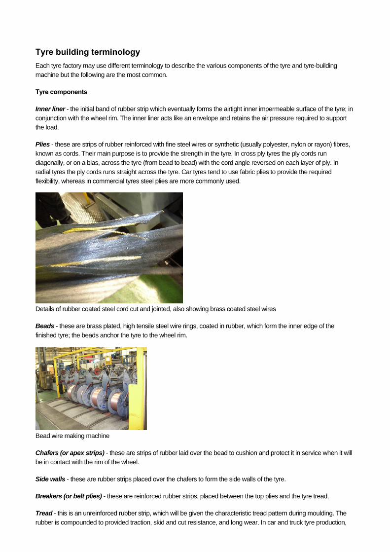
Plies - these are strips of rubber reinforced with fine steel wires or synthetic (usually polyester, nylon or rayon) fibres, known as cords. Their main purpose is to provide the strength in the tyre. In cross ply tyres the ply cords run diagonally, or on a bias, across the tyre (from bead to bead) with the cord angle reversed on each layer of ply. In
radial tyres the ply cords runs straight across the tyre. Car tyres tend to use fabric plies to provide the required flexibility, whereas in commercial tyres steel plies are more commonly used.
Details of rubber coated steel cord cut and jointed, also showing brass coated steel wires
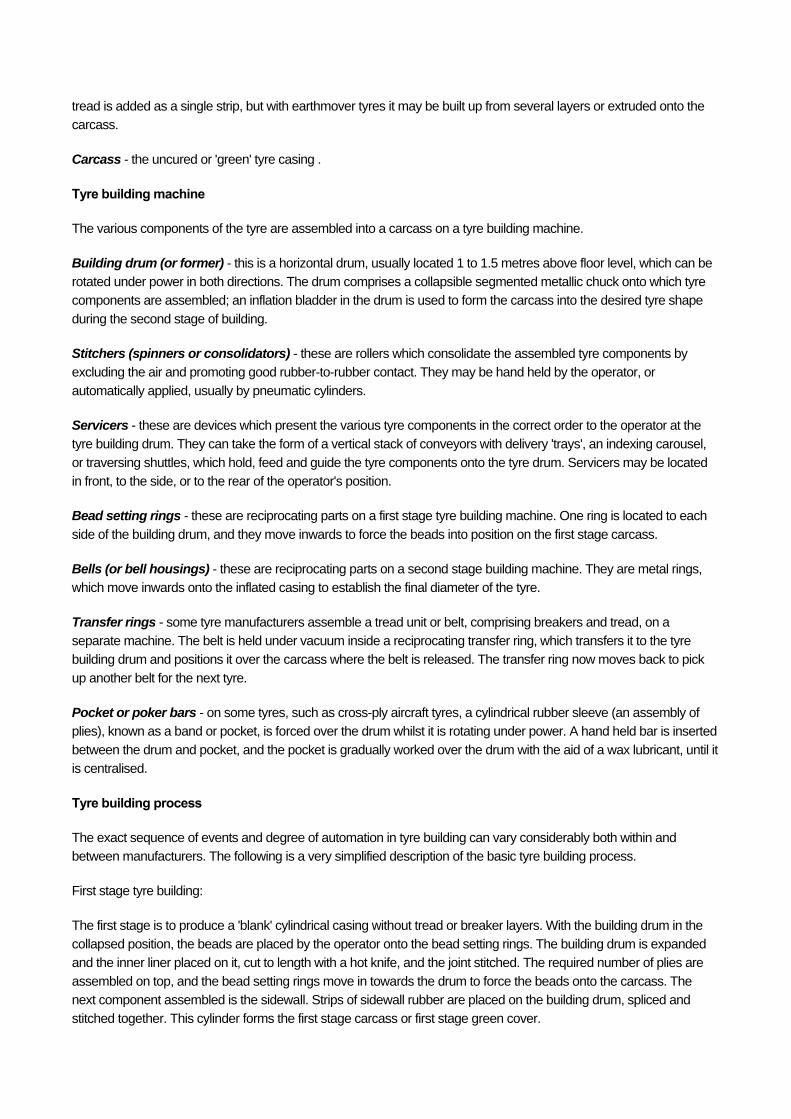
Beads - these are brass plated, high tensile steel wire rings, coated in rubber, which form the inner edge of the
finished tyre; the beads anchor the tyre to the wheel rim.
Bead wire making machine
Chafers (or apex strips) - these are strips of rubber laid over the bead to cushion and protect it in service when it will be in contact with the rim of the wheel.
Side walls - these are rubber strips placed over the chafers to form the side walls of the tyre.
Breakers (or belt plies) - these are reinforced rubber strips, placed between the top plies and the tyre tread.
Tread - this is an unreinforced rubber strip, which will be given the characteristic tread pattern during moulding. The
rubber is compounded to provided traction, skid and cut resistance, and long wear. In car and truck tyre production,
tread is added as a single strip, but with earthmover tyres it may be built up from several layers or extruded onto the carcass.
Carcass - the uncured or 'green' tyre casing .
Tyre building machine
The various components of the tyre are assembled into a carcass on a tyre building machine.
Building drum (or former) - this is a horizontal drum, usually located 1 to 1.5 metres above floor level, which can be rotated under power in both directions. The drum comprises a collapsible segmented metallic chuck onto which tyre components are assembled; an inflation bladder in the drum is used to form the carcass into the desired tyre shape
during the second stage of building.
Stitchers (spinners or consolidators) - these are rollers which consolidate the assembled tyre components by excluding the air and promoting good rubber-to-rubber contact. They may be hand held by the operator, or
automatically applied, usually by pneumatic cylinders.
Servicers - these are devices which present the various tyre components in the correct order to the operator at the tyre building drum. They can take the form of a vertical stack of conveyors with delivery 'trays', an indexing carousel,
or traversing shuttles, which hold, feed and guide the tyre components onto the tyre drum. Servicers may be located in front, to the side, or to the rear of the operator's position.
Bead setting rings - these are reciprocating parts on a first stage tyre building machine. One ring is located to each
side of the building drum, and they move inwards to force the beads into position on the first stage carcass.
Bells (or bell housings) - these are reciprocating parts on a second stage building machine. They are metal rings, which move inwards onto the inflated casing to establish the final diameter of the tyre.
Transfer rings - some tyre manufacturers assemble a tread unit or belt, comprising breakers and tread, on a separate machine. The belt is held under vacuum inside a reciprocating transfer ring, which transfers it to the tyre building drum and positions it over the carcass where the belt is released. The transfer ring now moves back to pick
up another belt for the next tyre.
Pocket or poker bars - on some tyres, such as cross-ply aircraft tyres, a cylindrical rubber sleeve (an assembly of plies), known as a band or pocket, is forced over the drum whilst it is rotating under power. A hand held bar is inserted
between the drum and pocket, and the pocket is gradually worked over the drum with the aid of a wax lubricant, until it is centralised.
Tyre building process
The exact sequence of events and degree of automation in tyre building can vary considerably both within and between manufacturers. The following is a very simplified description of the basic tyre building process.
First stage tyre building:
The first stage is to produce a 'blank' cylindrical casing without tread or breaker layers. With the building drum in the collapsed position, the beads are placed by the operator onto the bead setting rings. The building drum is expanded and the inner liner placed on it, cut to length with a hot knife, and the joint stitched. The required number of plies are
assembled on top, and the bead setting rings move in towards the drum to force the beads onto the carcass. The next component assembled is the sidewall. Strips of sidewall rubber are placed on the building drum, spliced and stitched together. This cylinder forms the first stage carcass or first stage green cover.
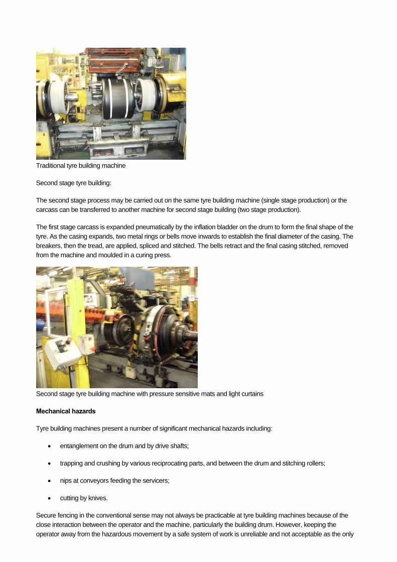
Traditional tyre building machine
Second stage tyre building:
The second stage process may be carried out on the same tyre building machine (single stage production) or the carcass can be transferred to another machine for second stage building (two stage production).
The first stage carcass is expanded pneumatically by the inflation bladder on the drum to form the final shape of the
tyre. As the casing expands, two metal rings or bells move inwards to establish the final diameter of the casing. The breakers, then the tread, are applied, spliced and stitched. The bells retract and the final casing stitched, removed from the machine and moulded in a curing press.
Second stage tyre building machine with pressure sensitive mats and light curtains
Mechanical hazards
Tyre building machines present a number of significant mechanical hazards including:
entanglement on the drum and by drive shafts;
trapping and crushing by various reciprocating parts, and between the drum and stitching rollers;
nips at conveyors feeding the servicers;
cutting by knives.
Secure fencing in the conventional sense may not always be practicable at tyre building machines because of the close interaction between the operator and the machine, particularly the building drum. However, keeping the
operator away from the hazardous movement by a safe system of work is unreliable and not acceptable as the only
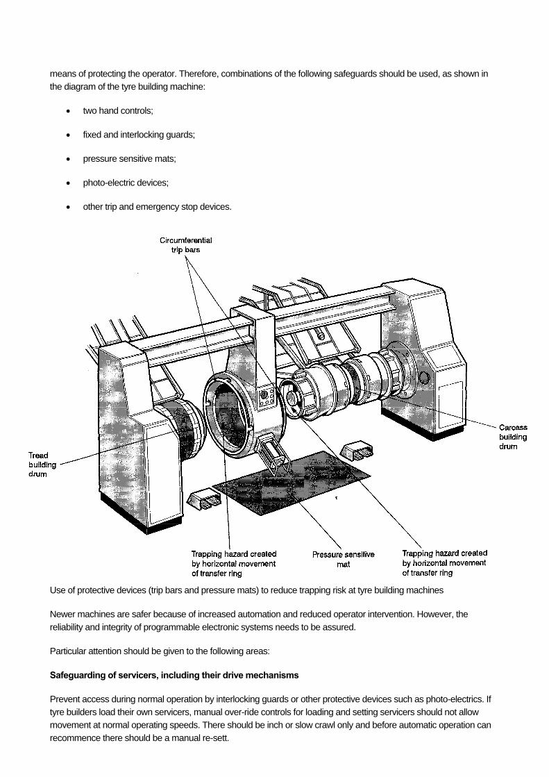
means of protecting the operator. Therefore, combinations of the following safeguards should be used, as shown in the diagram of the tyre building machine:
two hand controls;
fixed and interlocking guards;
pressure sensitive mats;
photo-electric devices;
other trip and emergency stop devices.
Use of protective devices (trip bars and pressure mats) to reduce trapping risk at tyre building machines
Newer machines are safer because of increased automation and reduced operator intervention. However, the
reliability and integrity of programmable electronic systems needs to be assured.
Particular attention should be given to the following areas:
Safeguarding of servicers, including their drive mechanisms
Prevent access during normal operation by interlocking guards or other protective devices such as photo-electrics. If tyre builders load their own servicers, manual over-ride controls for loading and setting servicers should not allow movement at normal operating speeds. There should be inch or slow crawl only and before automatic operation can
recommence there should be a manual re-sett.

Safeguarding of the building drum
Use photoelectric devices or pressure sensitive mats to prevent access to the rotating drum during automatic operation. For manual operation, provide two-hand control, or where this is not practicable, shrouded hold-to-run controls. These should have a spring-loaded shroud cover, and an un-shrouded emergency stop located at the
operator's position. Uncontrolled movement of pocket bars has resulted in serious hand and arm injuries so eliminate their use where
possible. Proprietary mechanical or pneumatic devices such as a Wyko applicator can replace pocket bars for tyres up to a certain size.
Other hazards
In order to increase 'tack' and promote adhesion between tyre components, small quantities of harmful and highly flammable solvents, usually petroleum naphtha blends SBPs, are manually applied by brush or pad. Prevention of skin contact is important to minimise the risk of dermatitis. There may also be exposure to carcinogenic mineral oils in
oil-extended rubber. Use safety containers for dispensing solvent.
Noise levels at tyre building machines are typically 77-88 dB(A). Levels will be higher where there are several machines together.
Manually handling compound; reels, spools and bobbins of wire and fabric and moving tyres, particularly the larger truck and earthmover tyres, can present a risk of injury. See the manual handling section in Health and safety topics for further information on controlling the risks.
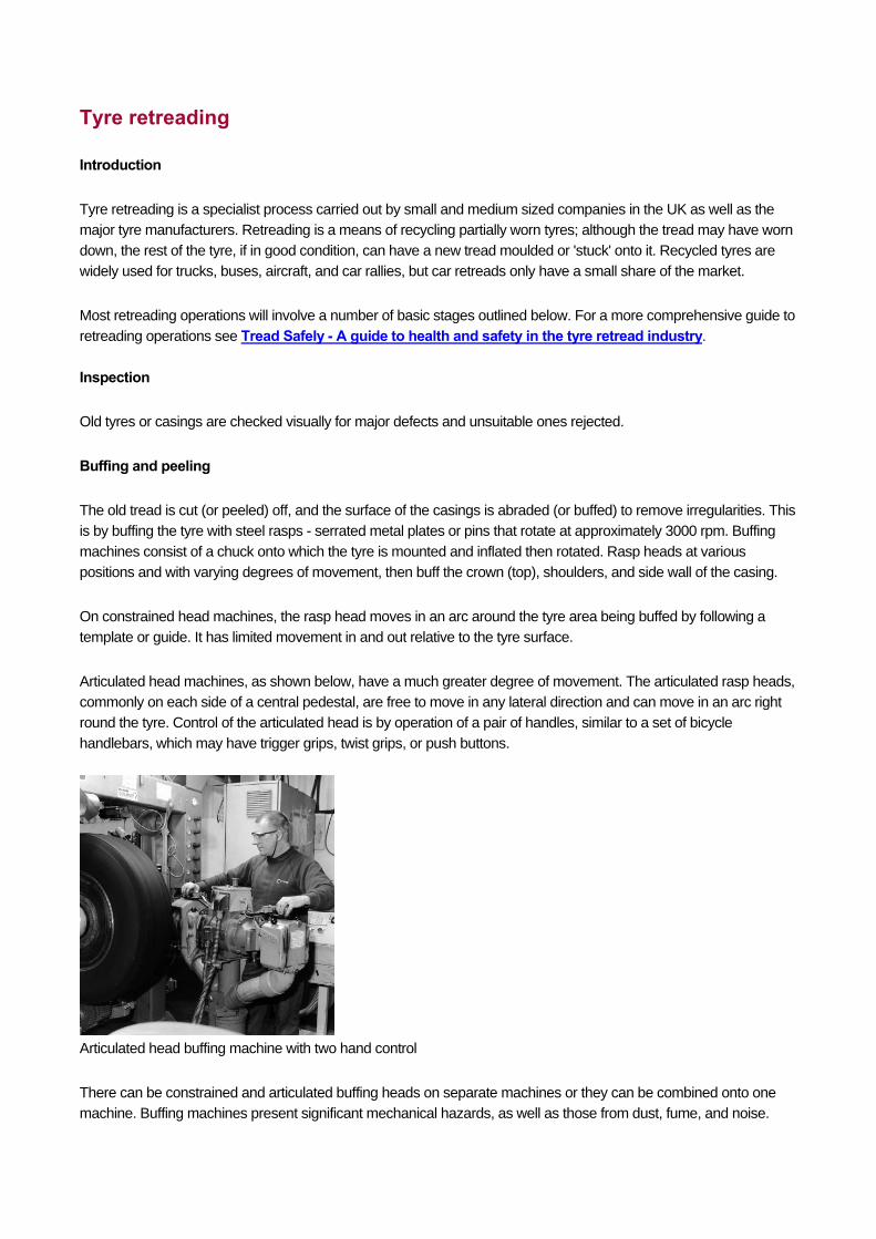
Tyre retreading
Introduction
Tyre retreading is a specialist process carried out by small and medium sized companies in the UK as well as the
major tyre manufacturers. Retreading is a means of recycling partially worn tyres; although the tread may have worn
down, the rest of the tyre, if in good condition, can have a new tread moulded or 'stuck' onto it. Recycled tyres are
widely used for trucks, buses, aircraft, and car rallies, but car retreads only have a small share of the market.
Most retreading operations will involve a number of basic stages outlined below. For a more comprehensive guide to
retreading operations see Tread Safely - A guide to health and safety in the tyre retread industry.
Inspection
Old tyres or casings are checked visually for major defects and unsuitable ones rejected.
Buffing and peeling
The old tread is cut (or peeled) off, and the surface of the casings is abraded (or buffed) to remove irregularities. This
is by buffing the tyre with steel rasps - serrated metal plates or pins that rotate at approximately 3000 rpm. Buffing
machines consist of a chuck onto which the tyre is mounted and inflated then rotated. Rasp heads at various
positions and with varying degrees of movement, then buff the crown (top), shoulders, and side wall of the casing.
On constrained head machines, the rasp head moves in an arc around the tyre area being buffed by following a
template or guide. It has limited movement in and out relative to the tyre surface.
Articulated head machines, as shown below, have a much greater degree of movement. The articulated rasp heads,
commonly on each side of a central pedestal, are free to move in any lateral direction and can move in an arc right
round the tyre. Control of the articulated head is by operation of a pair of handles, similar to a set of bicycle
handlebars, which may have trigger grips, twist grips, or push buttons.
Articulated head buffing machine with two hand control
There can be constrained and articulated buffing heads on separate machines or they can be combined onto one
machine. Buffing machines present significant mechanical hazards, as well as those from dust, fume, and noise.
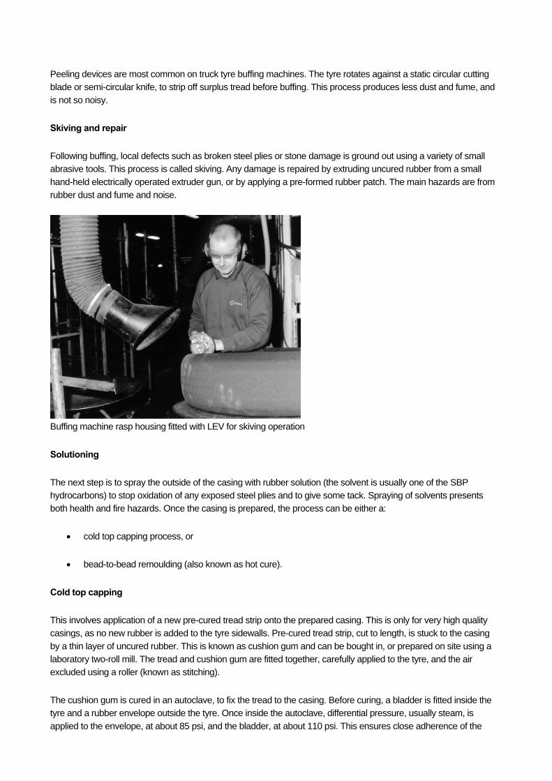
Peeling devices are most common on truck tyre buffing machines. The tyre rotates against a static circular cutting
blade or semi-circular knife, to strip off surplus tread before buffing. This process produces less dust and fume, and
is not so noisy.
Skiving and repair
Following buffing, local defects such as broken steel plies or stone damage is ground out using a variety of small
abrasive tools. This process is called skiving. Any damage is repaired by extruding uncured rubber from a small
hand-held electrically operated extruder gun, or by applying a pre-formed rubber patch. The main hazards are from
rubber dust and fume and noise.
Buffing machine rasp housing fitted with LEV for skiving operation
Solutioning
The next step is to spray the outside of the casing with rubber solution (the solvent is usually one of the SBP
hydrocarbons) to stop oxidation of any exposed steel plies and to give some tack. Spraying of solvents presents
both health and fire hazards. Once the casing is prepared, the process can be either a:
cold top capping process, or
bead-to-bead remoulding (also known as hot cure).
Cold top capping
This involves application of a new pre-cured tread strip onto the prepared casing. This is only for very high quality
casings, as no new rubber is added to the tyre sidewalls. Pre-cured tread strip, cut to length, is stuck to the casing
by a thin layer of uncured rubber. This is known as cushion gum and can be bought in, or prepared on site using a
laboratory two-roll mill. The tread and cushion gum are fitted together, carefully applied to the tyre, and the air
excluded using a roller (known as stitching).
The cushion gum is cured in an autoclave, to fix the tread to the casing. Before curing, a bladder is fitted inside the
tyre and a rubber envelope outside the tyre. Once inside the autoclave, differential pressure, usually steam, is
applied to the envelope, at about 85 psi, and the bladder, at about 110 psi. This ensures close adherence of the
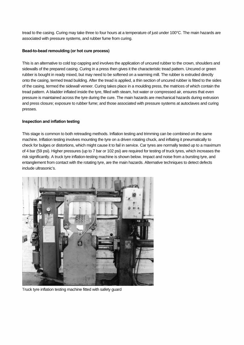
tread to the casing. Curing may take three to four hours at a temperature of just under 100°C. The main hazards are
associated with pressure systems, and rubber fume from curing.
Bead-to-bead remoulding (or hot cure process)
This is an alternative to cold top capping and involves the application of uncured rubber to the crown, shoulders and
sidewalls of the prepared casing. Curing in a press then gives it the characteristic tread pattern. Uncured or green
rubber is bought in ready mixed, but may need to be softened on a warming mill. The rubber is extruded directly
onto the casing, termed tread building. After the tread is applied, a thin section of uncured rubber is fitted to the sides
of the casing, termed the sidewall veneer. Curing takes place in a moulding press, the matrices of which contain the
tread pattern. A bladder inflated inside the tyre, filled with steam, hot water or compressed air, ensures that even
pressure is maintained across the tyre during the cure. The main hazards are mechanical hazards during extrusion
and press closure; exposure to rubber fume; and those associated with pressure systems at autoclaves and curing
presses.
Inspection and inflation testing
This stage is common to both retreading methods. Inflation testing and trimming can be combined on the same
machine. Inflation testing involves mounting the tyre on a driven rotating chuck, and inflating it pneumatically to
check for bulges or distortions, which might cause it to fail in service. Car tyres are normally tested up to a maximum
of 4 bar (59 psi). Higher pressures (up to 7 bar or 102 psi) are required for testing of truck tyres, which increases the
risk significantly. A truck tyre inflation-testing machine is shown below. Impact and noise from a bursting tyre, and
entanglement from contact with the rotating tyre, are the main hazards. Alternative techniques to detect defects
include ultrasonic’s.
Truck tyre inflation testing machine fitted with safety guard
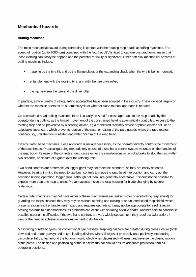
Mechanical hazards
Buffing machines
The main mechanical hazard during retreading is contact with the rotating rasp heads at buffing machines. The
speed of rotation (up to 3000 rpm) combined with the fact that LEV is fitted to capture dust and fume, mean that
loose clothing can easily be trapped and the potential for injury is significant. Other potential mechanical hazards at
buffing machines include:
trapping by the tyre lift, and by the flange plates or the expanding chuck when the tyre is being mounted;
entanglement with the rotating tyre, and with the tyre drive roller;
the nip between the tyre and the drive roller.
In practice, a wide variety of safeguarding approaches have been adopted in the industry. These depend largely on
whether the machine operates on automatic cycle or whether close manual approach is needed.
On constrained head buffing machines there is usually no need for close approach to the rasp heads by the
operator during buffing, as the limited movement of the constrained head is automatically controlled. Access to the
rotating rasp can be prevented by a sensing device, eg a monitored proximity device or photo-electric cell, or an
adjustable linear cam, which prevents rotation of the rasp, or raising of the rasp guards where the rasp rotates
continuously, until the tyre is inflated and within 50 mm of the rasp head.
On articulated head machines, close approach is usually necessary, as the operator directly controls the movement
of the rasp heads. Practical guarding methods rely on use of a two-hand control system mounted on the handles of
the rasp body. Release of the controls should cause either the simultaneous action of a brake to stop the rasp within
two seconds, or closure of a guard over the rotating rasp.
Two-hand controls are preferable, as trigger grips may not meet this standard, as they are easily defeated.
However, bearing in mind the need to use both controls to move the rasp head into position and carry out the
precision buffing operation, trigger grips, although not ideal, are generally acceptable. It should not be possible to
expose more than one rasp at once. Prevent access inside the rasp housing for blade changing by secure
fastenings.
Certain older machines may not have either of these mechanisms (ie braked motor or interlocking rasp shield) for
guarding the rasps. Instead, they may rely on manual opening and closing of an un-interlocked rasp shield, which
presents a significant entanglement hazard and requires upgrading. It may not be appropriate to retrofit injection
braking systems to older machines, as problems can occur with shearing of drive shafts. Another point to consider is
possible ergonomic difficulties if the two-hand controls are very widely spaced, or if they require a twist action, in
view of the need to achieve sideways movement to do the job.
Most curing of retread tyres use conventional tyre presses. Trapping hazards are created during press closure (both
powered and under gravity) and at tyre loading devices. Many designs of press rely on a positively interlocking
circumferential trip bar around the bottom mould, which when depressed will arrest and reverse the closing motion
of the press. The design and positioning of the sensitive trip bar should ensure adequate protection from all
operating positions.
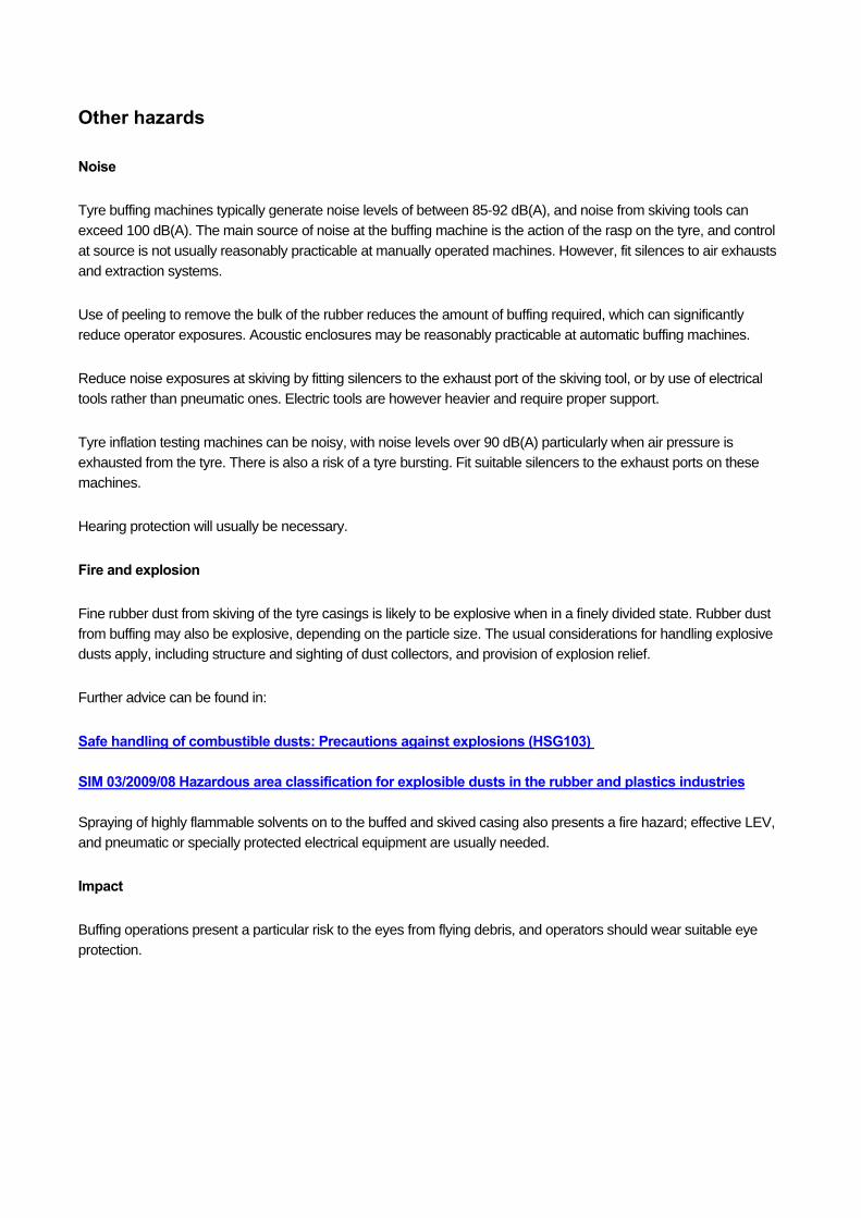
Other hazards
Noise
Tyre buffing machines typically generate noise levels of between 85-92 dB(A), and noise from skiving tools can
exceed 100 dB(A). The main source of noise at the buffing machine is the action of the rasp on the tyre, and control
at source is not usually reasonably practicable at manually operated machines. However, fit silences to air exhausts
and extraction systems.
Use of peeling to remove the bulk of the rubber reduces the amount of buffing required, which can significantly
reduce operator exposures. Acoustic enclosures may be reasonably practicable at automatic buffing machines.
Reduce noise exposures at skiving by fitting silencers to the exhaust port of the skiving tool, or by use of electrical
tools rather than pneumatic ones. Electric tools are however heavier and require proper support.
Tyre inflation testing machines can be noisy, with noise levels over 90 dB(A) particularly when air pressure is
exhausted from the tyre. There is also a risk of a tyre bursting. Fit suitable silencers to the exhaust ports on these
machines.
Hearing protection will usually be necessary.
Fire and explosion
Fine rubber dust from skiving of the tyre casings is likely to be explosive when in a finely divided state. Rubber dust
from buffing may also be explosive, depending on the particle size. The usual considerations for handling explosive
dusts apply, including structure and sighting of dust collectors, and provision of explosion relief.
Further advice can be found in:
Safe handling of combustible dusts: Precautions against explosions (HSG103) SIM 03/2009/08 Hazardous area classification for explosible dusts in the rubber and plastics industries
Spraying of highly flammable solvents on to the buffed and skived casing also presents a fire hazard; effective LEV,
and pneumatic or specially protected electrical equipment are usually needed.
Impact
Buffing operations present a particular risk to the eyes from flying debris, and operators should wear suitable eye
protection.