
Introduction to Polymeric Geomembranes COPYRIGHTED … · 2020-02-24 · specific, unique demands...
20
1 Introduction to Polymeric Geomembranes 1.1 INTRODUCTION The large number of commercially available geomembranes (or polymeric geosynthetic barriers) can make it challenging to select which geomembrane has the most appropriate combination of performance properties for a given application. Each type of geomem- brane material has different characteristics that affect its installation procedures, durability, lifespan and overall performance. It is therefore necessary to match the project perfor- mance criteria with the right combination of properties of a particular geomembrane. Geomembrane materials are generally selected for their overall performance in key areas of chemical resistance, mechanical properties (elastic modulus, yield strength, punc- ture/tear resistance), weathering resistance, product life expectancy, installation factors and cost effectiveness. The properties of polymeric geomembranes are determined mainly by their polymer structure (architecture of the chains), molecular weight (i.e. the length of the chains) and the crystallinity (packing density of the chains). Polymer crystallinity is one of the important properties of all polymers. Polymers exist both in crystalline and amorphous forms. Common geomembranes can be classified into two broad categories depending on whether they are thermoplastics (i.e. can be remelted) or thermoset (i.e. crosslinked or cured and hence cannot be remelted without degradation) (see Table 1.1). Since thermoset geomembranes are crosslinked, they can exhibit excellent long-term durability. When selecting a geomembrane for a particular application the following aspects need to be considered: • choice of polymer; • type of fabric reinforcement; • colour of upper ply (e.g. white to maintain lower temperatures for sun exposed appli- cations); • thickness; A Guide to Polymeric Geomembranes: A Practical Approach J. Scheirs © 2009 John Wiley & Sons, Ltd COPYRIGHTED MATERIAL
Transcript of Introduction to Polymeric Geomembranes COPYRIGHTED … · 2020-02-24 · specific, unique demands...

1
Introduction to PolymericGeomembranes
1.1 INTRODUCTION
The large number of commercially available geomembranes (or polymeric geosyntheticbarriers) can make it challenging to select which geomembrane has the most appropriatecombination of performance properties for a given application. Each type of geomem-brane material has different characteristics that affect its installation procedures, durability,lifespan and overall performance. It is therefore necessary to match the project perfor-mance criteria with the right combination of properties of a particular geomembrane.Geomembrane materials are generally selected for their overall performance in key areasof chemical resistance, mechanical properties (elastic modulus, yield strength, punc-ture/tear resistance), weathering resistance, product life expectancy, installation factorsand cost effectiveness.
The properties of polymeric geomembranes are determined mainly by their polymerstructure (architecture of the chains), molecular weight (i.e. the length of the chains)and the crystallinity (packing density of the chains). Polymer crystallinity is one of theimportant properties of all polymers. Polymers exist both in crystalline and amorphousforms.
Common geomembranes can be classified into two broad categories depending onwhether they are thermoplastics (i.e. can be remelted) or thermoset (i.e. crosslinked orcured and hence cannot be remelted without degradation) (see Table 1.1). Since thermosetgeomembranes are crosslinked, they can exhibit excellent long-term durability.
When selecting a geomembrane for a particular application the following aspects needto be considered:
• choice of polymer;• type of fabric reinforcement;• colour of upper ply (e.g. white to maintain lower temperatures for sun exposed appli-
cations);• thickness;
A Guide to Polymeric Geomembranes: A Practical Approach J. Scheirs© 2009 John Wiley & Sons, Ltd
COPYRIG
HTED M
ATERIAL

2 A GUIDE TO POLYMERIC GEOMEMBRANES
Table 1.1 Main plastic classifications for common geomembrane types
Thermoplastic Thermoset Combinationsgeomembranes geomembranes of thermoplastic
and thermoset
HDPE, LLDPE CSPE (crosslinks over time) PE-EPDMfPP EPDM rubber PVC-nitrile rubberPVC Nitrile rubber EPDM/TPE (Trelleborg)EIA Butyl rubber Polymer-modified bitumenTPU, PVDF Polychloroprene (Neoprene)
• texture (e.g. smooth or textured for improved friction angles);• product life expectancy;• mechanical properties;• chemical resistance;• ease of installation.
Table 1.2 lists various advantages and disadvantages of common geomembrane types.Firstly, geomembrane quality begins with base polymer resin selection. It is important
to select or specify high-grade polymer resins that have been manufactured to meet thespecific, unique demands encountered by geomembranes. Polymeric geomembrane prop-erties are a function of the chemical structure of the base polymer resin, the molecularweight, the molecular weight distribution and the polymer morphology (e.g. the crys-tallinity). Next it is necessary to select the right combination of additives to protect thegeomembrane, such as premium carbon black as well as antioxidant additives and stabi-lizers to ensure long life even in exposed conditions. Finally, it is necessary to select themost appropriate geomembrane manufacturing method.
1.2 VISCOELASTIC BEHAVIOUR
Polymers exhibit both viscous and elastic characteristics when undergoing deformationand hence are termed viscoelastic. Viscous materials (like honey), resist shear flow andstrain linearly with time when a stress (e.g. in-service loading) is applied. Elastic materialsstrain (i.e. elongate) instantaneously when stretched and quickly return to their originalstate once the stress is removed (e.g. as in the case of EPDM liners). Viscoelastic materialshave elements of both of these properties and, as such, exhibit time dependent strain.
Some phenomena in viscoelastic materials are:
1. If the strain is held constant, the stress decreases with time (this is called relaxation).2. If the stress is held constant, the strain increases with time (this is called creep, as
can be observed with HDPE liners).
Viscoelastic behavior comprised of elastic and viscous components is modelled as linearcombinations of springs and dashpots, respectively.
The Maxwell model for viscoelastic behaviour can be represented by a viscous dashpot(a piston in oil) and an elastic spring connected in series, as shown in Figure 1.1(a). In

INTRODUCTION TO POLYMERIC GEOMEMBRANES 3
Table 1.2 Advantages and disadvantages of commonly used synthetic geomembranes
Geomembrane Advantages Disadvantages
HDPE Broad chemical resistance Potential for stress crackingGood weld strength High degree of thermal expansionGood low temperature properties Poor puncture resistanceRelatively inexpensive Poor multiaxial strain properties
LLDPE Better flexibility than HDPE Inferior UV resistance to HDPEBetter layflat than HDPE Inferior chemical resistance to HDPEGood multiaxial strain properties
fPP Can be factory fabricated and foldedso fewer field fabricated seams
Limited resistance to hydrocarbonsand chlorinated water
Excellent multiaxial propertiesGood conformabilityBroad seaming temperature window
PVC Good workability and layflatbehaviour
Poor resistance to UV and ozoneunless specially formulated
Easy to seam Poor resistance to weatheringCan be folded so fewer field
fabricated seamsPoor performance at high and low
temperaturesCSPE Outstanding resistance to UV and
ozoneCannot be thermally welded after
ageingGood performance at low
temperaturesGood resistance to chemicals, acids
and oilsEPDM Good resistance to UV and ozone Low resistance to oils, hydrocarbons
and solventsHigh strength characteristics Poor seam qualityGood low temperature performanceExcellent layflat behaviour
Butyl rubber Good resistance to UV andweathering
Relatively low mechanical properties
Good resistance to ozone Low tear strengthLow resistance to hydrocarbonsDifficult to seam
Nitrile rubber Good resistance to oils and fuels (butnot biodiesel)
Poor ozone resistance unless properlyformulated
Poor tear strength
this model if the polymer is put under a constant strain, the stresses gradually relax. Thatis, the tension in the spring (the stress) is gradually reduced by movement of the piston inthe dashpot after a strong elongation (or displacement). Stress relaxation describes howpolymers relieve stress under constant strain.
The Kelvin–Voigt model for viscoelastic behaviour also known as the Voigt model,consists of a viscous dashpot and Hookean elastic spring connected in parallel, as shownin Figure 1.1(b). It is used to explain the creep behaviors of polymers. When subjected

4 A GUIDE TO POLYMERIC GEOMEMBRANES
elastic
viscous
(a) Maxwell Model(stress relaxation)
(b) Kevin–Voigt Model(creep)
Figure 1.1 Polymers are viscoelastic materials having the properties of both viscousand elastic materials and can be modelled by combining elements that represent thesecharacteristics. One viscoelastic model, called the Maxwell model, predicts behaviorakin to a spring (elastic element) being in series with a dashpot (viscous element), whilethe Kelvin–Voigt model places these elements in parallel. Stress relaxation describeshow polymers relieve stress under constant strain. Because they are viscoelastic,polymers behave in a nonlinear, non-Hookean fashion. This nonlinearity is described byboth stress relaxation and a phenomenon known as creep, which describes howpolymers strain under constant stress
to a constant stress, viscoelastic materials experience a time-dependent increase in strain(i.e. change in length). This phenomenon is known as viscoelastic creep. In this modelon the application of a force, the spring gradually expands until the spring force equalsthe applied stress. Creep describes how polymers strain under constant stress.
The temperature dependence of strain in polymers can also be predicted using thismodel. An increase in temperature correlates to a logarithmic decrease in the time requiredto impart equal strain under a constant stress. In other words, it takes less energy to stretcha viscoelastic material an equal distance at a higher temperature than it does at a lowertemperature.
1.3 POLYMER STRUCTURE
Polymer structure describes the chemical makeup of the polymer chains. HDPE, forexample, is comprised of linear molecules of repeating CH2 groups as shown in Figure 1.2.
Chemical structures of the main classes of geomembranes are shown in Figure 1.3.Note that HDPE due to its regular, symmetrical structure is crystalline and quite stiff butby substituting one of the hydrogen atoms (shaded) with a bulky methyl group (as inflexible polypropylene) or an even more bulky chlorine atom (as in PVC) the crystallinityof the polymer is disrupted and the material becomes more flexible.
INTRODUCTION TO POLYMERIC GEOMEMBRANES 5
(a)
(b)
(c)
H H H H H H H H H H
H H H H H H H HEthylene Polyethylene
PolymerizationC C C C C C C C C C=
HH
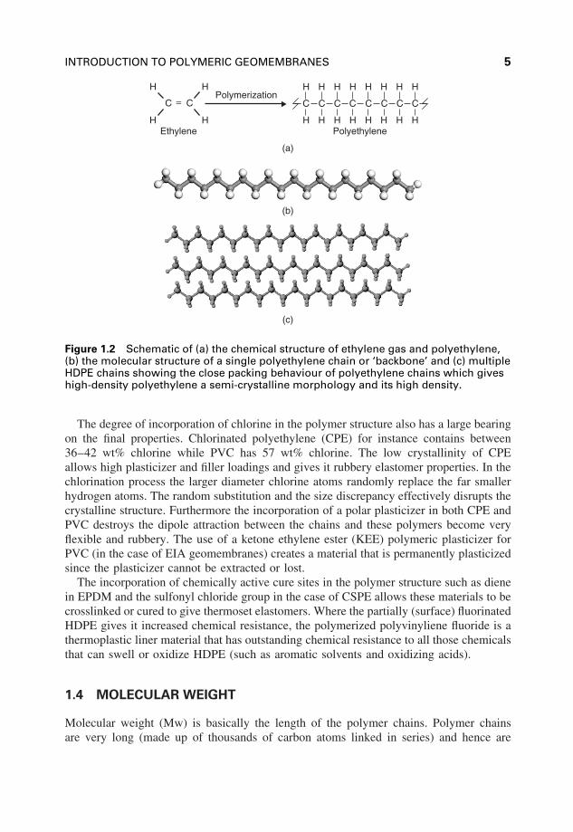
Figure 1.2 Schematic of (a) the chemical structure of ethylene gas and polyethylene,(b) the molecular structure of a single polyethylene chain or ‘backbone’ and (c) multipleHDPE chains showing the close packing behaviour of polyethylene chains which giveshigh-density polyethylene a semi-crystalline morphology and its high density.
The degree of incorporation of chlorine in the polymer structure also has a large bearingon the final properties. Chlorinated polyethylene (CPE) for instance contains between36–42 wt% chlorine while PVC has 57 wt% chlorine. The low crystallinity of CPEallows high plasticizer and filler loadings and gives it rubbery elastomer properties. In thechlorination process the larger diameter chlorine atoms randomly replace the far smallerhydrogen atoms. The random substitution and the size discrepancy effectively disrupts thecrystalline structure. Furthermore the incorporation of a polar plasticizer in both CPE andPVC destroys the dipole attraction between the chains and these polymers become veryflexible and rubbery. The use of a ketone ethylene ester (KEE) polymeric plasticizer forPVC (in the case of EIA geomembranes) creates a material that is permanently plasticizedsince the plasticizer cannot be extracted or lost.
The incorporation of chemically active cure sites in the polymer structure such as dienein EPDM and the sulfonyl chloride group in the case of CSPE allows these materials to becrosslinked or cured to give thermoset elastomers. Where the partially (surface) fluorinatedHDPE gives it increased chemical resistance, the polymerized polyvinyliene fluoride is athermoplastic liner material that has outstanding chemical resistance to all those chemicalsthat can swell or oxidize HDPE (such as aromatic solvents and oxidizing acids).
1.4 MOLECULAR WEIGHT
Molecular weight (Mw) is basically the length of the polymer chains. Polymer chainsare very long (made up of thousands of carbon atoms linked in series) and hence are

6 A GUIDE TO POLYMERIC GEOMEMBRANES
PVDF C C
F
H
F
Hn
C C
H
H
H
H
HDPE n
C C
H
H
CH3
H
PPn
C C
H
H
Cl
H
PVCn
C C
H
H
Cl*
H
CPEn
C C
H
H
F*
H
FHDPEn
PVC/KEE(EIA)
C C
H
H
Cl
Hn
C C
H
H
H
Hy
C
O
xC O
O
zester
ethylene
ketone
n denotes mulitple numbers of repeat units* denotes less than stoiciometric amount of designated atom
EPDM C C
H
H
H
H
C C
H
H H
C C
H Hx y z
diene
C C
H
Cl*
H
CSPEn
SO2Cl 86.6% H
14.3% Cl
1.1% SO2Cl
fPP C C
H
H
H
H
C C
H
H Hx y
where y is greater than x
CH3
CH3
Figure 1.3 Chemical structures and repeat units of various geomembrane polymers.Note the most basic repeat unit is that of HDPE. Substitution of a hydrogen atom in theHDPE structure confers properties such as greater flexibility, greater polarity, greatersolvent resistance and the ability to undergo crosslinking
also referred to as macromolecules. In general terms, as the polymer molecular weightincreases, the geomembrane strength increases.
The molecular weight of the polymer can affect physical properties such as the tensilestrength and modulus, impact strength, puncture resistance, flexibility and heat resistanceas well as its long-term durability properties.
It is difficult to measure the molecular weight directly so generally a simpler way ofexpressing molecular weight is by the melt index (MI) (also referred to as melt flow index(MFI) or melt flow rate (MFR)). The melt index is inversely proportional to the polymer’smolecular weight. For example, a low melt index value indicates higher molecular weightand stiffer melt flow behavior (i.e. higher melt viscosity) while a high melt index valueindicates a lower molecular weight and easier melt flow (i.e. low melt viscosity) (Scheirs,2000). Note: MFI is not applicable to PVC polymers.
Table 1.3 shows the effect of molecular weight and melt index on polymer properties.HDPE geomembrane resins are generally high MW resins and therefore have low melt
flow index values (see Figure 1.4). For this reason they are referred to as ‘fractionalmelt’ and ‘HLMI’ (high load melt index) resins. The term ‘HLMI’ HDPE refers to thosepolyethylene resins that should really be called High Molecular Weight resins with anHLMI of less than 15 g/10 min using ASTM D1238, Condition F (21.6 kg load).

INTRODUCTION TO POLYMERIC GEOMEMBRANES 7
Table 1.3 Effect of molecular weight and melt index on polymer properties
Property As Molecular weight increases As melt index increases
Molecular weight (chain length) Increases DecreasesTensile strength (at yield) Increases DecreasesTensile elongation Increases DecreasesStiffness Increases DecreasesImpact strength Increases DecreasesStress crack resistance Increases DecreasesPermeability Decreases IncreasesChemical resistance Increases DecreasesAbrasion resistance Increases DecreasesProcessability Decreases Increases
Melt index (g /10 min)
0 2 4 6 8
Elo
ngat
ion
at b
reak
(%
)
600
500
400
300
200
100
0
typical MI range for HDPE geomembranes (0.1–0.6 g /10 min)
Figure 1.4 Relationship between melt flow index and % elongation at break for MDPE.Note the typical MI range for HDPE geomembranes (when tested with a 2.16 kg weightat 190 ◦C.)
The relationship between polymer molecular weight and melt index is summarized inTable 1.4
In addition to the length of the polymer chains (i.e. the molecular weight) the mechanicaland physical properties of the plastics are also influenced by the bonds within and betweenchains, chain branching and the degree of crystallinity.
1.5 MOLECULAR WEIGHT DISTRIBUTION
The molecular weight distribution (MWD) is a fundamental polymer property whichdetermines the processability and the end use properties of the polymer. Since an increasein the molecular weight of a polymer improves the physical properties, there is a strong

8 A GUIDE TO POLYMERIC GEOMEMBRANES
Table 1.4 Molecular weight and melt index relationship
Classification Number Molecular (Mw) MI (2.16 kg) MI (21.6 kg)of carbon weight standard high load
atoms melt index melt index
Medium MW 7500–12 000 100 000–180 000 0.6–10 25–50High MW 18 000–56 000 250 000–750 000 0.06–0.15 7–25
demand for polymers having high molecular weights. However, it is the high molecularweight molecules that render the polymer more difficult to process. A broadening in themolecular weight distribution tends to improve the flow of the polymer when it is beingprocessed at high rates of shear as the low molecular weight tail acts as a “processingaid” for the higher MW chains.
Thus due to the high viscosity of higher molecular weight resins such as low HLMIHDPE used for geomembranes, the molecular weight distribution becomes a very impor-tant consideration in the processability of these HDPE resins. Resin manufacturers can tai-lor the molecular weight distribution (MWD) by catalyst and process selection. Geomem-brane resins benefit from a broad to very broad distribution. While narrow distributionresins are tougher than broad distribution resins (at equivalent molecular weights), pro-cessability becomes easier as the MWD broadens. Table 1.5 shows the effect of molecularweight distribution on polymer geomembrane properties.
1.6 CRYSTALLINITY
In addition to the chemical structure, the properties of polymers are very dependent onthe polymer morphology – particularly crystallinity.
The term crystallinity refers to the presence of crystalline regions where the poly-mer chains pack efficiently into dense regions that are impervious to both oxygen andchemicals (see Figures 1.5). Hence highly crystalline polyethylene has excellent chemicalresistance and oxidative stability.
The ordered and aligned portions of the polymer chain form small regions that are calledcrystallites. The non-ordered regions are called amorphous. These amorphous regions that
Table 1.5 Effect of molecular weight distribution (MWD)on polymer geomembrane properties
Property As molecular weight distribution broadens
Stiffness DecreasesImpact strength DecreasesStress crack resistance IncreasesMelt strength IncreasesProcessability Increases
INTRODUCTION TO POLYMERIC GEOMEMBRANES 9
folded polymer chainsin semi-crystalline polymers
tie molcecules connectthe crystallites
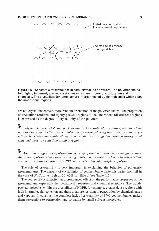
Figure 1.5 Schematic of crystallites in semi-crystalline polymers. The polymer chainsfold tightly in densely packed crystallites which are impervious to oxygen andchemicals. The crystallites (or lamellae) are interconnected by tie molecules which spanthe amorphous regions
are not crystalline contain more random orientation of the polymer chains. The proportionof crystalline (ordered and tightly packed) regions to the amorphous (disordered) regionsis expressed as the degree of crystallinity of the polymer.
Polymer chains can fold and pack together to form ordered (crystalline) regions. Theseregions where parts of the polymer molecules are arranged in regular order are called crys-tallites. In between these ordered regions molecules are arranged in a random disorganizedstate and these are called amorphous regions.
Amorphous regions of a polymer are made up of randomly coiled and entangled chains.Amorphous polymers have lower softening points and are penetrated more by solvents thanare their crystalline counterparts. PVC represents a typical amorphous polymer.
The role of crystallinity is very important in explaining the behavior of polymericgeomembranes. The amount of crystallinity of geomembrane materials varies from nil inthe case of PVC, to as high as 55–65% for HDPE (see Table 1.6).
The degree of crystallinity has a pronounced effect on the performance properties of thegeomembrane, especially the mechanical properties and chemical resistance. The tightlypacked molecules within the crystallites of HDPE, for example, creates dense regions withhigh intermolecular cohesion and these areas are resistant to penetration by chemical, gasesand vapours. In constrast the complete lack of crystallinity of PVC geomembranes makesthem susceptible to permeation and solvation by small solvent molecules.

10 A GUIDE TO POLYMERIC GEOMEMBRANES
Table 1.6 Typical % crystallinity values for variousgeomembrane polymers
Polymer Crystallinity (%) (average values)
HDPE 55MDPE 40LLDPE 15VLDPE 10FPP 5CPE 1–2PVC 0
The highly crystalline nature of HDPE is responsible for its higher density and stiffness,as well as its low permeability and high chemical resistance.
HDPE is semi-crystalline but introducing an alkene comonomer (e.g. butene or hexene)into the polymer backbone gives side chains that reduces the crystallinity. This in turn hasa dramatic effect on polymer performance, which improves significantly as the side-chainbranch length increases up to hexene, and becomes less significant with octene and longerchains. It is by manipulating this side branching that various grades of polyethylenevarying in crystallinity are produced.
The greater number of crystalline regions is what differentiates HDPE from itslower density cousins such as LLDPE, MDPE, LDPE and VLPE. This semi-crystallinemicrostructure of HDPE imparts excellent chemical resistance and high strength; howeverit also makes HDPE susceptible to environmental stress cracking (ESC). fPP, CPE andPVC owing to their low crystallinities are more flexible and not susceptible to ESC (seeFigure 1.6).
Polymer chains with side branches (e.g. LLDPE) or irregular pendant groups (e.g. PVC,CSPE) cannot pack together regularly enough to form crystallites. This is the reason whyLLDPE and VLDPE, which have a controlled number of side branches, have much lowercrystallinities than HDPE.
HDPE crystallizes from the melt under typical conditions as densely packed morpho-logical structures known as spherulites. These are small spherical objects (usually from1 to 10 μm) in diameter composed of even smaller structural subunits: rod-like fibrilsthat spread in all directions from the spherulite centres, occupying the spherulite volume.These fibrils, in turn, are made up of the smallest morphological structures distinguish-able, small planar crystallites called lamellae. These crystallites contain folded polymerchains that are perpendicular to the lamella plane and tightly bend every 5 to 15 nm (seeFigure 1.7).
Lamellae are interconnected by a few polymer chains, which pass from one lamella,through a small amorphous region, to another. These connecting chains, or tie molecules,are ultimately responsible for mechanical integrity and strength of all semi-crystallinepolymer materials. Crystalline lamellae offer the spherulites rigidity and account for theirhigh softening temperatures, whereas the amorphous regions between lamellae provideflexibility and high impact strength to HDPE products.

INTRODUCTION TO POLYMERIC GEOMEMBRANES 11
C C
H
H
H
H
HDPE n
C C
H
H
Cl
Hn
n denotes mulitple numbers of repeat units
* denotes less than stoiciometric amount of designated atom
C C
H
H
Cl*
H
CPEn
Decreasing Crystallinity
Increasing Amorphous Character
Increasing Flexibility
plasticizedPVC
fPP C C
H
H
H
H
C C
H
H
CH3
Hx y
where y is greater than x
Figure 1.6 Effect that the substitution of a hydrogen atom in HDPE by substituents ofincreasing size (e.g. methyl group, chlorine atom) has on the crystallinity and theflexibility of the polymer
Highly crystalline polymers are rigid, high melting and less affected by solvent penetra-tion. Hence HDPE geomembranes which have some 55–60% crystallinity exhibit excellentsolvent resistance. Crystallinity makes polymers strong, but also lowers their impact resis-tance. For instance, samples of HDPE prepared with crystallinities of 95% are extremelybrittle.
An increase in the degree of crystallinity leads to a direct increase in rigidity and tensilestrength at yield point, hardness and softening point and to a reduction in diffusion andpermeability. However increasing crystallinity also means a reduction in the number of‘tie’ molecules in the amorphous regions which are susceptible to chemical attack (e.g.oxidation) and tie chain pullout from the crystallites (i.e. stress cracking) (see Figure 1.8).
Increasing crystallinity results in the following property attributes: increased tensilestrength, increased stiffness or hardness, increased chemical resistance, decreased diffu-sive permeability (or vapour transmission), decreased elongation or strain at failure anddecreased stress crack resistance.
In semi-crystalline polymers, the antioxidants reside in the amorphous regions whichfortuitously are the same regions where oxygen can diffuse into cause oxidation. In con-trast, the crystallites are too dense for either oxygen or antioxidant and diffuse into. Themore amorphous polyolefins are more prone to oxidative degradation since oxygen can

12 A GUIDE TO POLYMERIC GEOMEMBRANES
amorphouspolymer
crystallinelamella
Spherulite boundary
Amorphous lamella
Crystaline lamella
Nucleation site
Figure 1.7 Schematic of spherulites in semi-crystalline polymers
diffuse more freely throughout their entire structure and there is a greater volume of poly-mer that must be protected by the antioxidant. In addition, antioxidants can also diffusemore readily through and migrate more easily from amorphous polymers compared totheir more crystalline forms (Scheirs, 2000).
Crystalline thermoplastics (also called semi-crystalline) include HDPE, LLDPE andpolypropylene. In these materials the polymeric chains are folded in a crystal lattice. Thefolded chains form lamellae (plate-like crystals).
Whilst the crystallites (i.e. tightly packed crystalline regions) are impervious to bothoxygen and chemical ingress, the ‘tie’ molecules which interconnect the crystallites aresusceptible to oxidation and chemical attack. The area in which the tie molecules reside istermed the amorphous region (i.e. disordered region) and these areas have lower densitythan the crystallites and so oxygen and opportunistic chemical can diffuse into these areas.

INTRODUCTION TO POLYMERIC GEOMEMBRANES 13
Crystalline Regions
(a)
(b)
Figure 1.8 Schematics of (a) the chain folding and packing behaviour of high-densitypolyethylene chains to form crystalline regions and (b) the crystalline regions or‘crystallites’ in HDPE (which are interconnected by ‘tie molecules’) which can be pulledapart under the combined action of stress and a chemical agent (referred to asenvironmental stress cracking). Reprinted with permission from Polymer, Importanceof tie molecules in preventing polyethylene fracture under long-term loading conditionsby A. Lustiger and R. L. Markham, 24(12), 1647. Copyright (1983) Elsevier

14 A GUIDE TO POLYMERIC GEOMEMBRANES
1.7 PROPERTIES OF POLYETHYLENES
Polyethylene is by far the most widely used polymer to manufacture geomembranes.Polyethylene resins are manufactured in very-low-density, low-density, linear low-den-sity, medium-density and high-density varieties. The density range for all polyethylenegeomembrane polymers falls within the general limits of 0.85 to 0.960 g/cm3.
Molecular weight, molecular weight distribution and crystallinity (i.e. density) are thethree most important characteristics of polyethylene resins and play a major role indetermining the durability and end-use performance properties of HDPE and LLDPEgeomembranes.
Polyethylene is classified into several categories based on its density and branching.HDPE has little branching, giving it stronger intermolecular forces and higher tensilestrength than lower density polyethylene, thereby making it ideal for geomembrane appli-cations. HDPE is defined as having a density of equal to or greater than 0.941 g/cc.
The density of polyethylene is primarily controlled by the frequency and length of theside branches (which in turn are determined by the type and level of comonomer). Theside branches prevent the PE chains from packing closely together, so the longer the sidebranches, the more open the structure and hence the lower the density. HomopolymerHDPE has a density greater than 0.960 g/cc while copolymers have densities less than0.960 g/cc.
Note that true homopolymer HDPE is not used for geomembranes due to its tendencyto undergo environmental stress cracking.
Typical comonomers are butene, hexene and octene which are carbon chains with 4,6 and 8 carbons respectively. These comonomers are denoted as C4, C6 and C8 forsimplicity. They all have a reactive double bond at the end of the chain and are referredto as alpha olefins. The ‘olefin’ indicates they contain a C=C bond in their structure whilealpha indicates the double bond is between the first and second carbon atoms.
The type of comonomer used determines the end-use performance characteristics ofthe resin. Hexene and octene copolymers are tougher and more flexible; however butenecopolymers are typically less expensive.
It is important to emphasize that HDPE geomembranes are actually manufactured usinga polyethylene resin with a density 0.932–0.940 g/cm3 which falls into the MDPE categoryas defined in ASTM D-883. It is the addition of carbon black that pushes the finaldensity of the geomembrane up into the density range between 0.941 and 0.950 g/cm3
which corresponds to a HDPE as defined in ASTM D-883. For this reason the ‘HDPE’nomenclature is used to describe most black polyethylene geomembranes.
Note that ‘HDPE’ geomembrane resins are in fact MDPE base polymer with theaddition of 2% carbon black, which raises its density into the classification range of HDPE.
The effect of increasing density on various PE geomembrane properties is shown inTable 1.7.
Table 1.8 lists the density classifications for polyethylene resins.

INTRODUCTION TO POLYMERIC GEOMEMBRANES 15
Table 1.7 Effect of density on PE geomembraneproperties
Property As density increases
Crystallinity IncreasesTensile strength (at yield) IncreasesStiffness IncreasesImpact strength DecreasesStress crack resistance DecreasesPermeability DecreasesChemical resistance IncreasesAbrasion resistance IncreasesProcessability Decreases
Table 1.8 Density classifications for polyethylene resins
Polyethylene type Defined density range (g/cc)
HDPE 0.941–0.965MDPE 0.926–0.940LLDPE 0.915–0.925LDPE 0.910–0.915VLDPE 0.880–0.910
HDPE is the most common field-fabricated geomembrane material primarily due to itslow material cost, broad chemical resistance and excellent mechanical properties.
MDPE is a substantially linear polymer, with high levels of short-chain branches,commonly made by copolymerization of ethylene with short-chain alpha-olefins (e.g.1-butene, 1-hexene and 1-octene).
LLDPE is a substantially linear polymer, with significant numbers of short branches,commonly made by copolymerization of ethylene with short-chain alpha-olefins (e.g.1-butene, 1-hexene and 1-octene). As its name implies, Linear Low Density Polyethyleneis a lower density polymer (<0.939 g/cm3), with increased material flexibility. LLDPE ismainly used for liners where large settlements are anticipated for long term consolidation,such as for landfill covers. Capping contaminants with LLDPE geomembranes, not onlymakes it possible to control the release of carbon dioxide and methane (by-products ofthe decomposition of organic matter), but allows their capture and reuse. The flexibilityof the LLDPE is also useful for geomembrane liners that are installed on subgrades proneto differential settlement.
LLDPE has a higher tensile strength and higher impact and puncture resistance thanLDPE. It is very flexible and elongates under stress. It can be used to make thinner sheets,with better environmental stress cracking resistance. It has good resistance to chemicalsand to ultraviolet radiation (if properly stabilized). However it is not as easy to processas LDPE, has lower gloss and a narrower operating range for heat sealing. Hence itfinds application in plastic sheets (where it permits use of lower thickness profile thancomparable LDPE), coverings of cables, geomembranes and flexible tubing.

16 A GUIDE TO POLYMERIC GEOMEMBRANES
LLDPE geomembranes are available in a smooth, textured or single textured finish.The comonomers used to produce the resin can include hexene or octene.
Low-density polyethylene (LDPE) has very poor environmental stress crack resistanceand rather poor mechanical properties and so it does not find application as a geomem-brane. LDPE has a high degree of short- and long-chain branching, which means that thechains do not pack to form a dense crystal structure as well. It has therefore less strongintermolecular forces, as the instantaneous-dipole induced-dipole attraction is less. Thisresults in a lower tensile strength and increased ductility.
VLDPE is most commonly produced using metallocene catalysts and is a highly flexibleand ductile material.
1.8 STRESS–STRAIN BEHAVIOUR OF POLYMERS
The stress–strain behaviour of polymers used to manufacture geomembranes is largelydetermined by the properties discussed above, namely the molecular weight, molecularweight distribution and crystallinity or density.
Figure 1.9 shows a typical stress–strain curve for HDPE which identifies the following:
• the linear elastic region (where it obeys Hooke’s Law);• the plastic region where the polymer draws and extends;• the yield stress;• the ultimate strength (or tensile strength at break);• the modulus of elasticity (i.e. the gradient of the initial linear slope).
Hooke’s Lawσ = E ε
YieldStress
UltimateStrength
STRAIN, ε
STRESS–STRAIN CURVE FOR A TYPICAL VISCOELASTIC POLYMER
ST
RE
SS
, σ
E = Modulus of Elasticity = Young’s Modulus (Tensile Modulus)
plastic region
elasticregion
Figure 1.9 Stress–strain curve showing elastic and plastic regions

INTRODUCTION TO POLYMERIC GEOMEMBRANES 17
ELONGATIONAT YIELD
ELONGATION ATBREAK
ULTIMATESTRENGTH
YIELDSTRESS
ST
RE
SS
STRAIN
Figure 1.10 Stress–strain curve for HDPE showing main tensile test value parameters
Figure 1.10 is a similar stress–strain curve which also identifies the elongation at yield(also know as the yield strain) and the elongation at break (also known as the breakingstrain).
Figure 1.11 shows the stress–strain curves for various polymer types. If the load riseslinearly to fracture with no plastic deformation then the material is said to be brittle as isthe case for PVC liners where the plasticizers have been extracted or, for HDPE geomem-branes after extensive oxidation. More commonly though the behaviour of geomembranesis ductile but may exhibit brittle behaviour depending on the temperature. The brittletransition occurs at sub-zero temperatures for common geomembranes (see section onlow temperature properties) (Scheirs, 2000). For geomembranes applications either hardand tough (e.g. HDPE) or soft and tough (e.g. CSPE, fPP, EIA) polymers are the mostsuitable.
1.8.1 YIELD BEHAVIOUR
‘Yield’ is defined as the onset of plastic deformation in a polymer under an applied load.This is an important parameter because it represents the practical limit of use more thandoes ultimate break or rupture. The yield properties depend on the polymer crystallinityand the polymer morphology. The yield behaviour also depends on the test conditionsused. The yield properties vary with both the test temperature and the speed of the test.For this reason it is very important that tensile testing of polymer geomembranes beconducted at 23 ◦C where possible. This may therefore cast doubt on field tensiometermeasurements where higher or lower temperatures might be encountered. Since the speedof the tensile test is also critical, the tensile test speed (also known as the crosshead speedand determined by the strain rate) must be standardized and defined (Scheirs, 2000).

18 A GUIDE TO POLYMERIC GEOMEMBRANES
HARD ANDBRITTLE
HARD ANDSTRONG
HARD ANDTOUGH
SOFT ANDTOUGH
STRAIN
ST
RE
SS
Figure 1.11 Stress–strain curves for various polymer types
1.8.2 PLASTIC DEFORMATION
‘Plastic deformation’ is the deformation that remains after a load is removed from apolymer sample. It is also called permanent deformation or non-recoverable deforma-tion. Under small enough loads less than the yield stress the deformation is elasticand is recovered after the load is removed (i.e. the specimen returns to its originallength). Yielding thus represents the transition from elastic to plastic behaviour. Con-sider a HDPE geomembrane sample under an applied tensile load. The length of thespecimen will increase (as measured by the elongation). As the elongation increases,the load at first increases linearly but then increases more slowly and eventually passesthrough a maximum where the elongation increases without any increase in load (as inFigure 1.10). This peak in the stress–strain curve (i.e. the load–elongation curve) is thepoint at which plastic flow (permanent deformation) becomes dominant and is definedas the yield point. Not all polymers exhibit a defined yield point such as that exhib-ited by HDPE. PVC, for example, shows no obvious yield point in the stress–straincurve.
1.8.3 STRESS
The shape and magnitude of the load–elongation curve depends on the particular poly-meric geomembrane being tested. Rather than load, the properly normalized variable isstress which is defined as the load per unit cross-sectional area of the test specimen. Stresstherefore has units of pressure (1 MPa = 1 MN/m2 = 145 psi).

INTRODUCTION TO POLYMERIC GEOMEMBRANES 19
1.8.4 STRAIN
Rather than quoting elongation, the proper normalized variable is strain which is the exten-sion divided by the initial length. Strain is therefore dimensionless whereas elongation isexpressed as a percentage.
1.8.5 TYPES OF LOADING
The most common type of loading used for testing polymeric geomembranes is uniaxialtension but other types of loading are arguably more important such as compression,hydrostatic compression and uniaxial (i.e. multiaxial tensile) loading. The simplest varia-tion of the tensile test is the uniaxial compression test which should not be confused withhydrostatic compression in which the load is applied from all sides. It has been foundthat compressive stresses are higher than tensile stresses for a given strain value.
1.8.6 TEMPERATURE EFFECTS
The shape and magnitude of the stress–strain curve is very dependent on temperature. Asthe temperature increases, the yield stress, elastic modulus (i.e. stiffness) and yield energyall decrease while the yield strain (elongation at yield) increases (see Figure 1.12).
1.8.7 STRAIN RATE EFFECTS
Strain rate determines to the speed of the application of force on the material being tested.High strain rates (i.e. high testing speed) have the effect of making the polymer behave ina more brittle fashion – in the same way that reducing the temperature makes the polymerstiffer and more brittle (Figure 1.13).
Stress
Strain
Decreasing crystallinityIncreased swelling/plasticizationIncreasing temperature
Figure 1.12 Effect of swelling and increased temperature on the stress strainproperties of HDPE geomembranes. The material becomes softer and more rubbery butloses its tensile strength

20 A GUIDE TO POLYMERIC GEOMEMBRANES
Stress
Strain
Increasing densityIncreasing testing rateDecreasing temperature
Figure 1.13 Effect of increasing density or increasing testing rate (i.e. strain rate) ordecreasing temperature on the stress–strain properties of HDPE geomembranes. Thematerial becomes stiffer and stronger as the density or testing speed increase or astemperature is decreased
Table 1.9 Melting points of various polymer resins
Polymer Melting point (◦C)
Poly(ethylene vinyl acetate) (EVA) 85Metallocene polyethylene (mPE) 90–100Low-density polyethylene (LDPE) 108Linear low-density polyethylene (LLDPE) 125High-density polyethylene (HDPE) 130Flexible polypropylene (fPP) 150
1.9 MELTING POINTS
Polymer geomembrane resins have very different melting points as shown in Table 1.9.The polymer melting point (or more correctly the melting range) is of importance duringthermal welding; particularly when welding different geomembrane materials to eachother.
REFERENCES
Scheirs, J., Compositional and Failure Analysis of Polymers: A Practical Approach , JohnWiley & Sons, Ltd, Chichester, UK, 2000, 766 pp.


