Introduction to Plate Behaviour and Design
30
Previous | Next | Contents ESDEP WG 8 PLATES AND SHELLS Lecture 8.1: Introduction to Plate Behaviour and Design OBJECTIVE/SCOPE To introduce the series of lectures on plates, showing the uses of plates to resist in-plane and out-of-plane loading and their principal modes of behaviour both as single panels and as assemblies of stiffened plates. PREREQUISITES None. RELATED LECTURES Lecture 8.2: Behaviour and Design of Unstiffened Plates Lecture 8.3: Behaviour and Design of Stiffened Plates SUMMARY This lecture introduces the uses of plates and plated assemblies in steel structures. It describes the basic behaviour of plate panels subject to in- plane or out-of-plane loading, highlighting the importance of geometry and boundary conditions. Basic buckling modes and mode interaction are presented. It introduces the concept of effective width and describes the influence of imperfections on the behaviour of practical plates. It also gives an introduction to the behaviour of stiffened plates. 1. INTRODUCTION Plates are very important elements in steel structures. They can be assembled into complete members by the basic rolling process (as hot rolled sections), by folding (as cold formed sections) and by welding. The efficiency of such sections is due to their use of the high in-plane stiffness of one plate element to support the edge of its neighbour, thus controlling the out-of-plane behaviour of the latter.
-
Upload
mona-raftari -
Category
Documents
-
view
225 -
download
0
Transcript of Introduction to Plate Behaviour and Design

Previous | Next | Contents
ESDEP WG 8
PLATES AND SHELLS
Lecture 8.1: Introduction to Plate
Behaviour and Design
OBJECTIVE/SCOPE
To introduce the series of lectures on plates, showing the uses of plates to
resist in-plane and out-of-plane loading and their principal modes of
behaviour both as single panels and as assemblies of stiffened plates.
PREREQUISITES
None.
RELATED LECTURES
Lecture 8.2: Behaviour and Design of Unstiffened Plates
Lecture 8.3: Behaviour and Design of Stiffened Plates
SUMMARY
This lecture introduces the uses of plates and plated assemblies in steel
structures. It describes the basic behaviour of plate panels subject to in-plane or out-of-plane loading, highlighting the importance of geometry
and boundary conditions. Basic buckling modes and mode interaction are presented. It introduces the concept of effective width and describes the
influence of imperfections on the behaviour of practical plates. It also
gives an introduction to the behaviour of stiffened plates.
1. INTRODUCTION
Plates are very important elements in steel structures. They can be assembled into complete members by the basic rolling process (as hot
rolled sections), by folding (as cold formed sections) and by welding. The efficiency of such sections is due to their use of the high in-plane stiffness
of one plate element to support the edge of its neighbour, thus controlling
the out-of-plane behaviour of the latter.

The size of plates in steel structures varies from about 0,6mm thickness
and 70mm width in a corrugated steel sheet, to about 100mm thick and 3m width in a large industrial or offshore structure. Whatever the scale of
construction the plate panel will have a thickness t that is much smaller than the width b, or length a. As will be seen later, the most important
geometric parameter for plates is b/t and this will vary, in an efficient plate structure, within the range 30 to 250.
2. BASIC BEHAVIOUR OF A PLATE PANEL
Understanding of plate structures has to begin with an understanding of the modes of behaviour of a single plate panel.
2.1 Geometric and Boundary Conditions
The important geometric parameters are thickness t, width b (usually
measured transverse to the direction of the greater direct stress) and length a, see Figure 1a. The ratio b/t, often called the plate slenderness,
influences the local buckling of the plate panel; the aspect ratio a/b may also influence buckling patterns and may have a significant influence on
strength.


In addition to the geometric proportions of the plate, its strength is
governed by its boundary conditions. Figure 1 shows how response to different types of actions is influenced by different boundary conditions.
Response to in-plane actions that do not cause buckling of the plate is only influenced by in-plane, plane stress, boundary conditions, Figure 1b.
Initially, response to out-of-plane action is only influenced by the boundary conditions for transverse movement and edge moments, Figure
1c. However, at higher actions, responses to both types of action conditions are influenced by all four boundary conditions. Out-of-plane
conditions influence the local buckling, see Figure 1d; in-plane conditions influence the membrane action effects that develop at large
displacements (>t) under lateral actions, see Figure 1e.
2.2 In-plane Actions
As shown in Figure 2a, the basic types of in-plane actions to the edge of a
plate panel are the distributed action that can be applied to a full side, the patch action or point action that can be applied locally.

When the plate buckles, it is particularly important to differentiate between applied displacements, see Figure 2b and applied stresses, see
Figure 2c. The former permits a redistribution of stress within the panel;
the more flexible central region sheds stresses to the edges giving a valuable post buckling resistance. The latter, rarer case leads to an earlier
collapse of the central region of the plate with in-plane deformation of the loaded edges.

2.3 Out-of-plane Actions
Out-of-plane loading may be:
uniform over the entire panel, see for example Figure 3a, the base
of a water tank. varying over the entire panel, see for example Figure 3b, the side of
a water tank. a local patch over part of the panel, see for example Figure 3c, a
wheel load on a bridge deck.

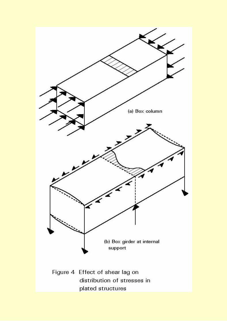
2.4 Determination of Plate Panel Actions
In some cases, for example in Figure 4a, the distribution of edge actions
on the panels of a plated structure are self-evident. In other cases the in-plane flexibilities of the panels lead to distributions of stresses that cannot
be predicted from simple theory. In the box girder shown in Figure 4b, the in-plane shear flexibility of the flanges leads to in-plane deformation
of the top flange. Where these are interrupted, for example at the change in direction of the shear at the central diaphragm, the resulting change in
shear deformation leads to a non-linear distribution of direct stress across the top flange; this is called shear lag.

In members made up of plate elements, such as the box girder shown in
Figure 5, many of the plate components are subjected to more than one component of in-plane action effect. Only panel A does not have shear
coincident with the longitudinal compression.


If the cross-girder system EFG was a means of introducing additional
actions into the box, there would also be transverse direct stresses arising from the interaction between the plate and the stiffeners.
2.5 Variations in Buckled Mode
i. Aspect ratio a/b
In a long plate panel, as shown in Figure 6, the greatest initial inhibition
to buckling is the transverse flexural stiffness of the plate between
unloaded edges. (As the plate moves more into the post-buckled regime, transverse membrane action effects become significant as the plate
deforms into a non-developable shape, i.e. a shape that cannot be formed just by bending).

As with any instability of a continuous medium, more than one buckled
mode is possible, in this instance, with one half wave transversely and in half waves longitudinally. As the aspect ratio increases the critical mode

changes, tending towards the situation where the half wave length a/m =
b. The behaviour of a long plate panel can therefore be modelled accurately by considering a simply-supported, square panel.
ii. Bending conditions
As shown in Figure 7, boundary conditions influence both the buckled
shapes and the critical stresses of elastic plates. The greatest influence is
the presence or absence of simple supports, for example the removal of simple support to one edge between case 1 and case 4 reduces the
buckling stress by a factor of 4,0/0,425 or 9,4. By contrast introducing rotational restraint to one edge between case 1 and case 2 increases the
buckling stress by 1,35.
iii. Interaction of modes

Where there is more than one action component, there will be more than
one mode and therefore there may be interaction between the modes. Thus in Figure 8b(i) the presence of low transverse compression does not
change the mode of buckling. However, as shown in Figure 8b(ii), high transverse compression will cause the panel to deform into a single half
wave. (In some circumstances this forcing into a higher mode may increase strength; for example, in case 8b(ii), predeformation/transverse
compression may increase strength in longitudinal compression.) Shear buckling as shown in Figure 8c is basically an interaction between the
diagonal, destabilising compression and the stabilising tension on the other diagonal.


Where buckled modes under the different action effects are similar, the
buckling stresses under the combined actions are less than the addition of individual action effects. Figure 9 shows the buckling interactions under
combined compression, and uniaxial compression and shear.
2.6 Grillage Analogy for Plate Buckling
One helpful way to consider the buckling behaviour of a plate is as the grillage shown in Figure 10. A series of longitudinal columns carry the
longitudinal actions. When they buckle, those nearer the edge have

greater restraint than those near the centre from the transverse flexural
members. They therefore have greater post buckling stiffness and carry a greater proportion of the action. As the grillage moves more into the post
buckling regime, the transverse buckling restraint is augmented by transverse membrane action.
2.7 Post Buckling Behaviour and Effective Widths

Figures 11a, 11b and 11c describe in more detail the changing distribution
of stresses as a plate buckles following the equilibrium path shown in Figure 11d. As the plate initially buckles the stresses redistribute to the
stiffer edges. As the buckling continues this redistribution becomes more extreme (the middle strip of slender plates may go into tension before the
plate fails). Also transverse membrane stresses build up. These are self equilibrating unless the plate has clamped in-plane edges; tension at the
mid panel, which restrains the buckling is resisted by compression at the edges, which are restrained from out-of-plane movement.


An examination of the non-linear longitudinal stresses in Figures 11a and
11c shows that it is possible to replace these stresses by rectangular stress blocks that have the same peak stress and same action effect. This
effective width of plate (comprising beff/2 on each side) proves to be a very effective design concept. Figure 11e shows how effective width
varies with slenderness (p is a measure of plate slenderness that is
independent of yield stress; p = 1,0 corresponds to values of b/t of 57,
53 and 46 for fy of 235N/mm2, 275N/mm2 and 355N/mm2 respectively).
Figure 12 shows how effective widths of plate elements may be combined to give an effective cross-section of a member.

2.8 The Influences of Imperfections on the Behaviour of Actual Plates
As with all steel structures, plate panels contain residual stresses from
manufacture and subsequent welding into plate assemblies, and are not perfectly flat. The previous discussions about plate panel behaviour all
relate to an ideal, perfect plate. As shown in Figure 13 these imperfections modify the behaviour of actual plates. For a slender plate
the behaviour is asymptotic to that of the perfect plate and there is little reduction in strength. For plates of intermediate slenderness (which
frequently occur in practice), an actual imperfect plate will have a considerably lower strength than that predicted for the perfect plate.


Figure 14 summarises the strength of actual plates of varying
slenderness. It shows the reduction in strength due to imperfections and the post buckling strength of slender plates.
2.9 Elastic Behaviour of Plates Under Lateral Actions
The elastic behaviour of laterally loaded plates is considerably influenced by its support conditions. If the plate is resting on simple supports as in
Figure 15b, it will deflect into a shape approximating a saucer and the corner regions will lift off their supports. If it is attached to the supports,
as in Figure 15c, for example by welding, this lift off is prevented and the

plate stiffness and action capacity increases. If the edges are encastre as
in Figure 15d, both stiffness and strength are increased by the boundary restraining moments.


Slender plates may well deflect elastically into a large displacement
regime (typically where d > t). In such cases the flexural response is significantly enhanced by the membrane action of the plate. This
membrane action is at its most effective if the edges are fully clamped. Even if they are only held partially straight by their own in-plane stiffness,
the increase in stiffness and strength is most noticeable at large deflections.
Figure 15 contrasts the behaviour of a similar plate with different
boundary conditions.
Figure 16 shows the modes of behaviour that occur if the plates are
subject to sufficient load for full yield line patterns to develop. The greater number of yield lines as the boundary conditions improve is a qualitative
measure of the increase in resistance.

3. BEHAVIOUR OF STIFFENED PLATES
Many aspects of stiffened plate behaviour can be deduced from a simple
extension of the basic concepts of behaviour of unstiffened plate panels. However, in making these extrapolations it should be recognised that:

"smearing" the stiffeners over the width of the plate can only model
overall behaviour. stiffeners are usually eccentric to the plate. Flexural behaviour of
the equivalent tee section induces local direct stresses in the plate panels.
local effects on plate panels and individual stiffeners need to be considered separately.
the discrete nature of the stiffening introduces the possibility of local modes of buckling. For example, the stiffened flange shown in
Figure 17a shows several modes of buckling. Examples are:
(i) plate panel buckling under overall compression plus any local
compression arising from the combined action of the plate panel with its attached stiffening, Figure 17b.
(ii) stiffened panel buckling between transverse stiffeners, Figure 17c.
This occurs if the latter have sufficient rigidity to prevent overall buckling. Plate action is not very significant because the only transverse member is
the plate itself. This form of buckling is best modelled by considering the stiffened panel as a series of tee sections buckling as columns. It should
be noted that this section is monosymmetric and will exhibit different behaviour if the plate or the stiffener tip is in greater compression.
(iii) overall or orthotropic bucking, Figure 17d. This occurs when the cross girders are flexible. It is best modelled by considering the plate assembly
as an orthotropic plate.


4. CONCLUDING SUMMARY
Plates and plate panels are widely used in steel structures to resist
both in-plane and out-of-plane actions. Plate panels under in-plane compression and/or shear are subject to
buckling. The elastic buckling stress of a perfect plate panel is influenced by:
plate slenderness (b/t).
aspect ratio (a/b).
boundary conditions.
interaction between actions, i.e. biaxial compression and
compression and shear.
The effective width concept is a useful means of defining the post-buckling behaviour of a plate panel in compression.
The behaviour of actual plates is influenced by both residual
stresses and geometric imperfections. The response of a plate panel to out-of-plane actions is influenced
by its boundary conditions. An assembly of plate panels into a stiffened plate structure may
exhibit both local and overall modes of instability.
5. ADDITIONAL READING
1. Timoshenko, S. and Weinowsky-Kreiger, S., "Theory of Plates and
Shells" Mc Graw-Hill, New York, International Student Edition, 2nd Ed.
Previous | Next | Contents