Introduction to PipelineCS510 Computer ArchitecturesLecture 6 - 1 Lecture 6 Introduction to...
21
Introduction to Pipeline CS510 Computer Architectures Lecture 6 - 1 Lecture 6 Lecture 6 Introduction to Introduction to Pipelining Pipelining
-
Upload
tyrese-bursey -
Category
Documents
-
view
218 -
download
1
Transcript of Introduction to PipelineCS510 Computer ArchitecturesLecture 6 - 1 Lecture 6 Introduction to...

Introduction to Pipeline CS510 Computer Architectures Lecture 6 - 1
Lecture 6Lecture 6
Introduction to Introduction to PipeliningPipelining
Lecture 6Lecture 6
Introduction to Introduction to PipeliningPipelining

Introduction to Pipeline CS510 Computer Architectures Lecture 6 - 2
Laundry Example• Ann, Brian, Cathy, Dave
each have one load of clothes to wash, dry, and fold
A B C D
Pipelining: Its Natural!Pipelining: Its Natural!
• Washer takes 30 minutes
• Dryer takes 40 minutes
• Folder takes 20 minutes
Introduction to Pipeline CS510 Computer Architectures Lecture 6 - 3
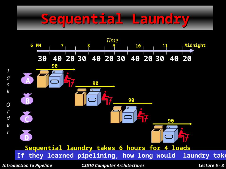
Sequential LaundrySequential Laundry
Task
Order
30 40 20 30 40 20 30 40 20 30 40 20
6 PM 7 8 9 10 11 MidnightTime
If they learned pipelining, how long would laundry take?Sequential laundry takes 6 hours for 4 loads
A
90
B
90
C
90
D
90

Introduction to Pipeline CS510 Computer Architectures Lecture 6 - 4
Pipelined LaundryPipelined LaundryStart Work ASAPStart Work ASAP
Task
Order
30 40 40 40 40 20
6 PM 7 8 9 10 11 Midnight
Time
Pipelined laundry takes 3.5 hours for 4 loads
A
90
B
90
C
90
D
90
Introduction to Pipeline CS510 Computer Architectures Lecture 6 - 5
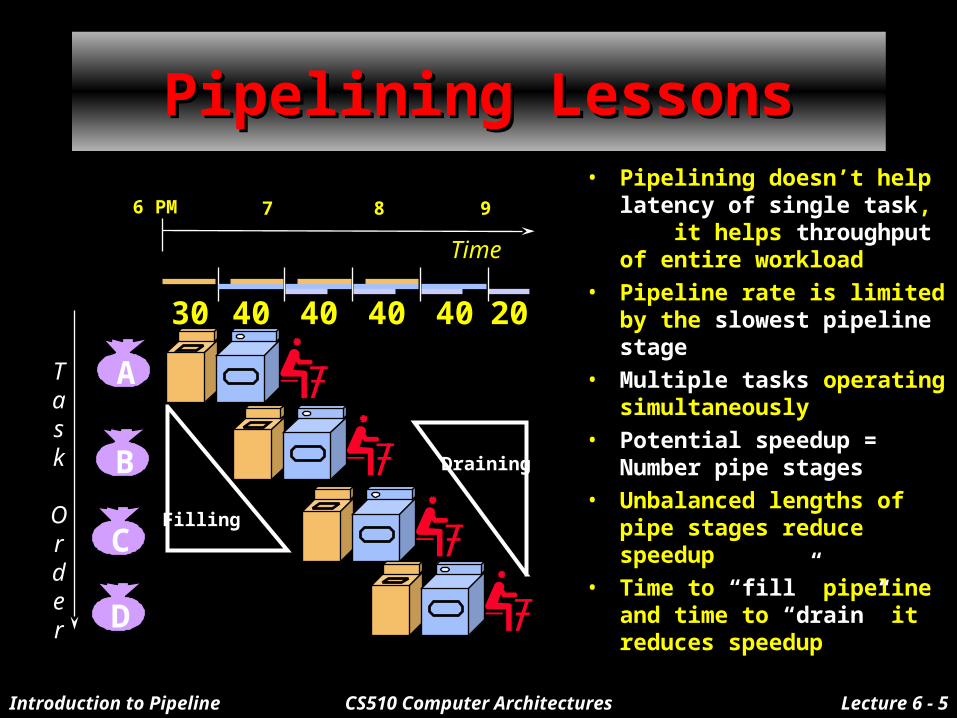
Pipelining LessonsPipelining Lessons• Pipelining doesn’t help
latency of single task, it helps throughput of entire workload
• Pipeline rate is limited by the slowest pipeline stage
• Multiple tasks operating simultaneously
• Potential speedup = Number pipe stages
• Unbalanced lengths of pipe stages reduce speedup
• Time to “fill” pipeline and time to “drain” it reduces speedup
Task
Order
6 PM 7 8 9
Time
30 40 40 40 40 20
A
B
C
D
Filling
Draining

Introduction to Pipeline CS510 Computer Architectures Lecture 6 - 6
DLX InstructionsDLX InstructionsInstruction type/ Instruction meaning Opcode
Data transfers Only memory address mode is 16-bit disp + contents of a GPR LB, LBU, SB Load byte, load byte unsigned, store byte
LH, LHU, SH Half word
LW, SW Word(to/from integer registers)
LF, LD, SF, SD Load SP float, load DP float, store SP float, store DP float
MOVI2S, MOVS2I Move from/to GPR to/from a special register
MOVF, MOVD Copy one FP register or a DP pair to another register or pair
MOVFP2I, MOVI2FP Move 32 bits from/to FP registers to/from integer registers
Arithmetic/logicalADD, ADDI, ADDU, ADDUI Add, add immediate(16 bits); signed and unsigned
SUB, SUBI, SUBU, SUBUI Subtract
MULT, MULTU, DIV, DIVU Multiply and divide, signed and unsigned; operands must be FP regs; all operations take and yield 32-bit values
AND, ANDI And, and immediate
OR, ORI, XOR, XORI OR, Exclusive-OR
LHI Load high immediate --- load upper half of register with immediate

Introduction to Pipeline CS510 Computer Architectures Lecture 6 - 7
DLX instructionsDLX instructionsShiftSLL, SRL, SRA, SLLI, Shifts: both immediate(S__I) and variable form (S__); logical, arithmetic
SRLI, SRAI
S__, S__I Set conditional: “__” may be LT, GT, LE, GE, EQ, NE
Control Conditional branches and jumps; PC-relative or through register
BEQZ, BNEZ Branch GPR equal/not equal to zero: 16-bit offset from PC+4
BFPT, BFPF Test comparison bit in the FP status register and branch; 16-bit offset
J, JR Jumps:26-bit offset or target in register
JAL, JALR Jump and link: save PC+4 in R31
TRAP Transfer to operating system at a vectored address
RFE Return to user code from an exception; restore user mode
Floating point FP operations on DP and SP formatFcnD, FcnF Fcn: ADD, SUB, MULT, DIV
CVTF2D, CVTF2I,Convert instructions: F single precision, D double precision, I integer
CVTD2F, CVTD2I, Both operands are FPRs
CVTI2F, CVTI2D,
__D, __F DP and SP compares: “__” = LT, GT, LE, GE, EQ, NE; sets bits in FP status register
Introduction to Pipeline CS510 Computer Architectures Lecture 6 - 8
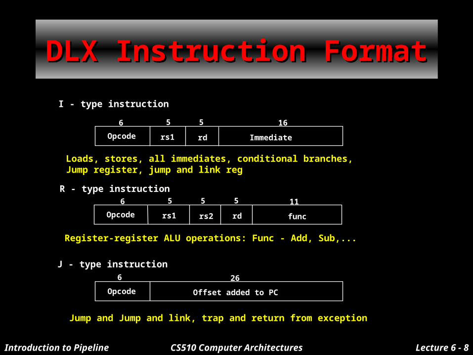
DLX Instruction FormatDLX Instruction Format
Opcode rs1 rd Immediate
6 5 5 16
I - type instruction
Loads, stores, all immediates, conditional branches, Jump register, jump and link reg
6 5 5
R - type instruction5 11
Opcode rs1 rs2 rd func
Register-register ALU operations: Func - Add, Sub,...
Opcode
6
J - type instruction
Offset added to PC
26
Jump and Jump and link, trap and return from exception

Introduction to Pipeline CS510 Computer Architectures Lecture 6 - 9
5 Steps of DLX Instr. Execution:5 Steps of DLX Instr. Execution:
Step1Step1
Step 1: Instruction fetch cycle (IF)– Read instruction from memory and store into IR
• IR Mem[PC]
– Calculate the next instruction address• NPC PC+4• 1 instruction is stored in consecutive 4 bytes
Instr.Memory
PC
Add
+4
NPC
IR

Introduction to Pipeline CS510 Computer Architectures Lecture 6 - 10
5 Steps of DLX Instr. Execution:5 Steps of DLX Instr. Execution:
Step2Step2
Step 2: Instruction decode/register fetch cycle (ID)– Read source registers to A and B
A Regs[IR6..10]B Regs[IR11..15]
– Make 16 bits sign extension of 16-bit immediate field to make a 32-bit immediate value
Imm ((IR16)16## IR16..31)
– Decoding is done in parallel: fixed-field decoding b Rd
SignExt
RegFile
16 32
IR
A
B
Imm
bRd
OP

Introduction to Pipeline CS510 Computer Architectures Lecture 6 - 11
5 Steps of DLX Instr. Execution:5 Steps of DLX Instr. Execution:
Step 3Step 3
Step 3: Execution/effective address cycle (EX):– Memory reference: Effective Address calculation
» ALUOutput A + Imm
– Register-register ALU instruction: Perform ALU operation with R’s» ALUOutput A func B; func B
– Register-Immediate ALU instruction: Perform ALU operation with
immediate operand» ALUOutput A op Imm
– Branch: Effective Address calculation for branch target address
Determine condition code» ALUOutput NPC + Imm; Cond (A op 0)

Introduction to Pipeline CS510 Computer Architectures Lecture 6 - 12
Step 3 EXStep 3 EX
Zero?
MU
XM
UX
ALU
NPC
A
B
Imm
ALUOut
Cond
OP

Introduction to Pipeline CS510 Computer Architectures Lecture 6 - 13
5 Steps of DLX Instr. Execution:5 Steps of DLX Instr. Execution: Step 4Step 4
Step 4: Memory access/branch completion cycle (MEM):– Memory reference : Access memory either
• for LD: LMD Mem[ALUOutput] or• for ST: Mem[ALUOutput] B
– Branch : Test Condition • if (cond) PC ALUOutput,
else PC NPC;
DataMemory
MU
X
ALUOut
NPC
Cond
PC
B
LMD

Introduction to Pipeline CS510 Computer Architectures Lecture 6 - 14
5 Steps of DLX Instr. Execution:5 Steps of DLX Instr. Execution: Step 5Step 5
Step 5: Write-back cycle (WB):Reg-Reg ALU : Store the result into the destination register
Regs[IR16..20] ALUOutput;
Reg-Immediate ALU : Store the result into destination registerRegs[IR11..15] ALUOutput;
Load instruction: Store the data read from memory to the destination register
Regs[IR11..15] LMD;
MU
XLMD
ALUOut
RegisterFile
OP

Introduction to Pipeline CS510 Computer Architectures Lecture 6 - 15
5 Steps of DLX Datapath5 Steps of DLX Datapath
MEM Stage
WB StageIF Stage ID Stage EX Stage
Instr.Memory
SignExt
Zero?
DataMemory
PC
MU
XM
UX
MU
X
MU
X
Add
ALURegFile
+4
16 32
SMD
ALUOutput
LMD
Introduction to Pipeline CS510 Computer Architectures Lecture 6 - 16
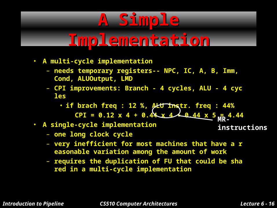
A Simple ImplementationA Simple Implementation
• A multi-cycle implementation
– needs temporary registers-- NPC, IC, A, B, Imm, Cond, ALUOutput, LMD
– CPI improvements: Branch - 4 cycles, ALU - 4 cycles
• if brach freq : 12 %, ALU instr. freq : 44%
CPI = 0.12 x 4 + 0.44 x 4 + 0.44 x 5 = 4.44
• A single-cycle implementation
– one long clock cycle
– very inefficient for most machines that have a reasonable variation among the amount of work
– requires the duplication of FU that could be shared in a multi-cycle implementation
MR-instructions

Introduction to Pipeline CS510 Computer Architectures Lecture 6 - 17
Visualizing PipelineVisualizing Pipeline
IM Reg
ALU
DM Reg
IM Reg
ALU
DM Reg
IM Reg
ALU
DM Reg
IM Reg
ALU
DM Reg
IM Reg
ALU
DM Reg
Instru
ction
O
rder
Time(clock cycles)
CC1 CC2 CC3 CC4 CC5 CC6 CC7 CC8 CC9
FillingFilling
DrainingDraining
Introduction to Pipeline CS510 Computer Architectures Lecture 6 - 18
Saving Information Produced Saving Information Produced by Each Stage of Pipelineby Each Stage of Pipeline
• Information need to be stored at the end of a clock cycle, otherwise it will be lost
• Each pipeline stage produces information(data, address, and control) at the end of the clock cycle
• Thus, we need a storage(called inter-stage buffer) at end of each pipeline stage
Introduction to Pipeline CS510 Computer Architectures Lecture 6 - 19
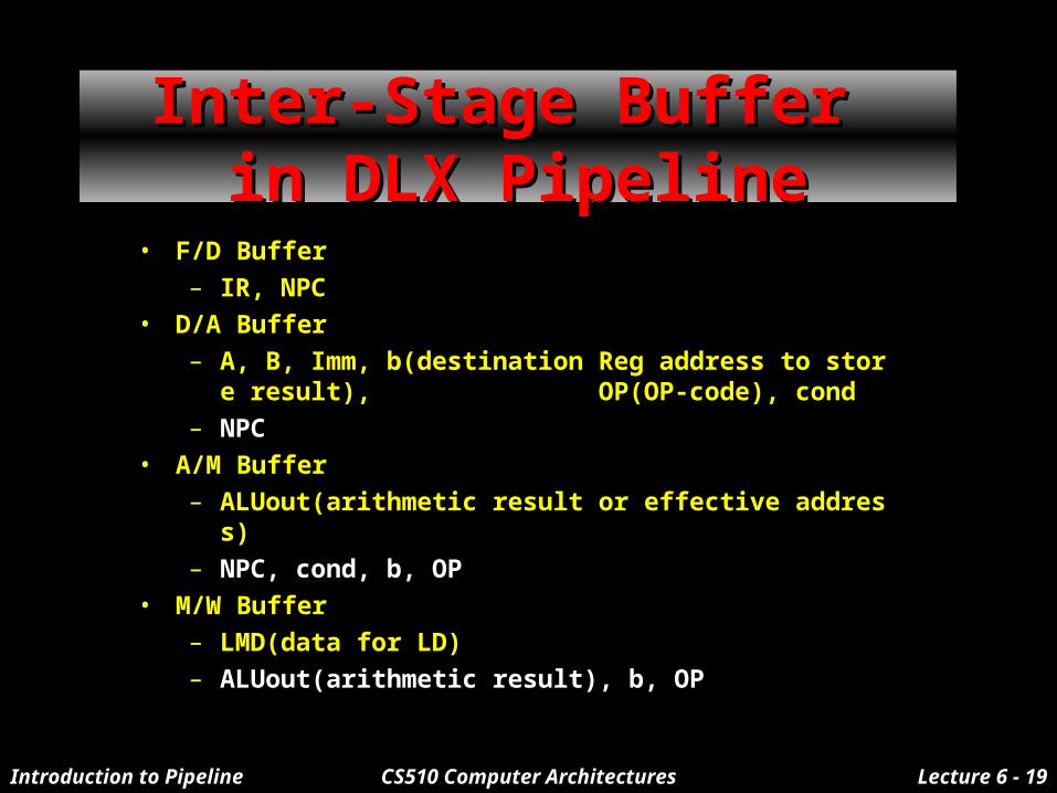
• F/D Buffer
– IR, NPC
• D/A Buffer
– A, B, Imm, b(destination Reg address to store result), OP(OP-code), cond
– NPC
• A/M Buffer
– ALUout(arithmetic result or effective address)
– NPC, cond, b, OP
• M/W Buffer
– LMD(data for LD)
– ALUout(arithmetic result), b, OP
Inter-Stage Buffer Inter-Stage Buffer in DLX Pipelinein DLX Pipeline

Introduction to Pipeline CS510 Computer Architectures Lecture 6 - 20
Pipelined DLX DatapathPipelined DLX Datapath- Multicycle -- Multicycle -
IF Stage
Instr.Memory
PC
Add
+4
MEM Stage
EX Stage
Zero?
MU
XM
UX
ALU
SMD
DataMemory
WB Stage
MU
XLMD
ID Stage
SignExt
RegFile
16 32
MU
X
F/D
B
uffer
D/A
B
uffer
A/M
B
uffer
M/W
B
uffer
F/D
B
uffer

Introduction to Pipeline CS510 Computer Architectures Lecture 6 - 21
ReminderReminder
• In conventional Single Port Memory, Instruction Memory and Data Memory are the same memory
– Both IF and Mem stages use memory
– One instruction uses the same hardware resource in two different cycles
– Two instructions try to use the same hardware resource in different stages of pipeline at the same time
• For Branch instructions, Branch Target Address is available in the Mem stage