Introduction to Offshore; Managed Pressure Drilling · on the Pergemine 7 land rig drilling the...
42
1
Transcript of Introduction to Offshore; Managed Pressure Drilling · on the Pergemine 7 land rig drilling the...

1

2
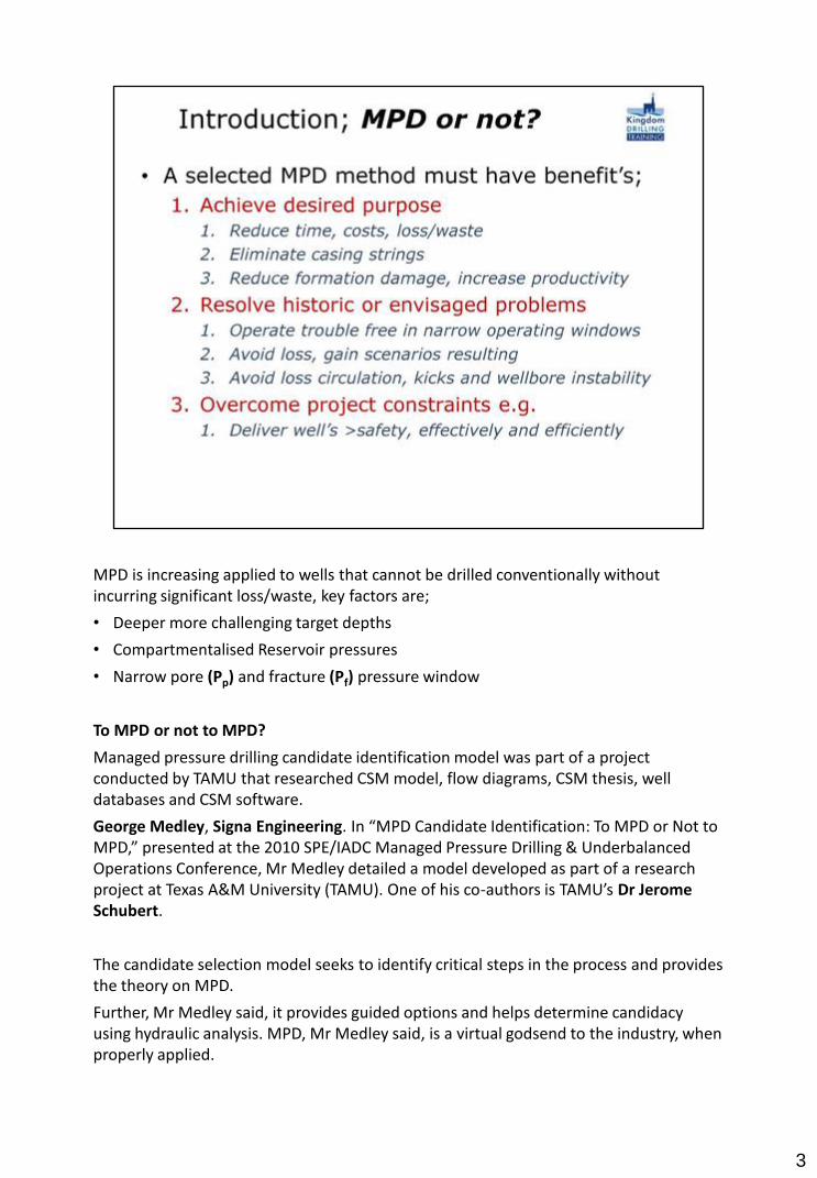
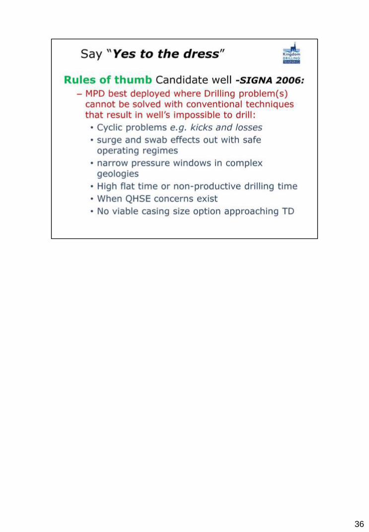
MPD is increasing applied to wells that cannot be drilled conventionally without incurring significant loss/waste, key factors are;
• Deeper more challenging target depths
• Compartmentalised Reservoir pressures
• Narrow pore (Pp) and fracture (Pf) pressure window
To MPD or not to MPD?
Managed pressure drilling candidate identification model was part of a project conducted by TAMU that researched CSM model, flow diagrams, CSM thesis, well databases and CSM software.
George Medley, Signa Engineering. In “MPD Candidate Identification: To MPD or Not to MPD,” presented at the 2010 SPE/IADC Managed Pressure Drilling & Underbalanced Operations Conference, Mr Medley detailed a model developed as part of a research project at Texas A&M University (TAMU). One of his co-authors is TAMU’s Dr Jerome Schubert.
The candidate selection model seeks to identify critical steps in the process and provides the theory on MPD.
Further, Mr Medley said, it provides guided options and helps determine candidacy using hydraulic analysis. MPD, Mr Medley said, is a virtual godsend to the industry, when properly applied.
3

“It’s filled a real gap in the technology that has allowed us to drill wells that were undrilled and to improve performance on wells that were drillable,” he remarked.
To begin the process, Mr Medley recommended defining objectives and collecting a variety of data – on wells, geology, equipment and design.
He urged that drilling problems be understood relative to the objectives.
Finally, learn the variations on the theme of MPD because there are several different types.
The candidate selection software draws from several databases of MPD wells drilled.
• The first, developed by Signa, breaks the MPD well data down by MPD variation, i.e., constant bottomhole pressure, dual gradient, pressure mud cap control drilling and so on.
• At Balance with Smith developed a second database that details wells by rig type.
• Finally, the database from Secure Drilling (now part of Weatherford International) also analyzes rig type, as well as project type (development, exploratory, HP, HPHT, etc).
3

4

5

6

By maintaining a continuous circulation flow, the circulating pressure and balance, ECD, can be set at the optimum to control the well and maximise bit RoP, the static mud density can be reduced as can the fluid loss into the producing formation. With steady state pressure, temperature and mud flow, throughout the drilling of the pay zone, the chances of exposing a cleaner, undamaged production formation are greatly enhanced. Generally, the higher production rate will be very worth while.
7
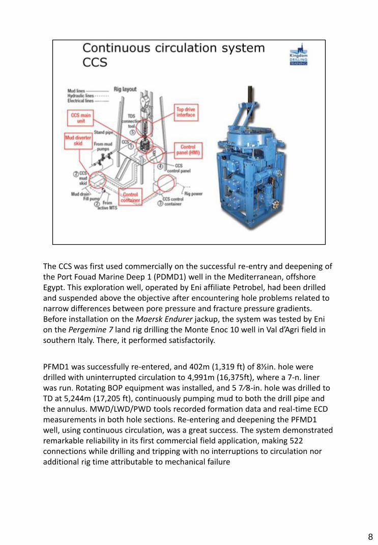
The CCS was first used commercially on the successful re-entry and deepening of the Port Fouad Marine Deep 1 (PDMD1) well in the Mediterranean, offshore Egypt. This exploration well, operated by Eni affiliate Petrobel, had been drilled and suspended above the objective after encountering hole problems related to narrow differences between pore pressure and fracture pressure gradients. Before installation on the Maersk Endurer jackup, the system was tested by Eni on the Pergemine 7 land rig drilling the Monte Enoc 10 well in Val d’Agri field in southern Italy. There, it performed satisfactorily.
PFMD1 was successfully re-entered, and 402m (1,319 ft) of 8½in. hole were drilled with uninterrupted circulation to 4,991m (16,375ft), where a 7-n. liner was run. Rotating BOP equipment was installed, and 5 7⁄8-in. hole was drilled to TD at 5,244m (17,205 ft), continuously pumping mud to both the drill pipe and the annulus. MWD/LWD/PWD tools recorded formation data and real-time ECD measurements in both hole sections. Re-entering and deepening the PFMD1 well, using continuous circulation, was a great success. The system demonstrated remarkable reliability in its first commercial field application, making 522 connections while drilling and tripping with no interruptions to circulation nor additional rig time attributable to mechanical failure
8
The CCS has proven to be a safe, reliable system that allows operators to successfully drill complex offshore wells and wells with narrow pore pressure/fracture pressure gradient windows that were previously difficult to drill, time-consuming and expensive. It can also be used with Closed Hole Circulation Drilling to drill reservoirs, where formation damage and impaired production can be reduced, maintaining continuous circulation and controlling the EMW overbalance. The system has proven to be safe and reliable to operate, and has successfully achieved its programed drilling objectives
9

1. Wellbore Stress Augmentation raises fracture initiation pressure.
2. Fracture Propagation Resistance fracture initiation pressure unchanged, but stable fracture propagation range is extended.
3. Combination of 1& 2
10

https://www.slb.com/~/media/Files/resources/oilfield_review/ors11/win11/03_stabilizing.pdf
11

12

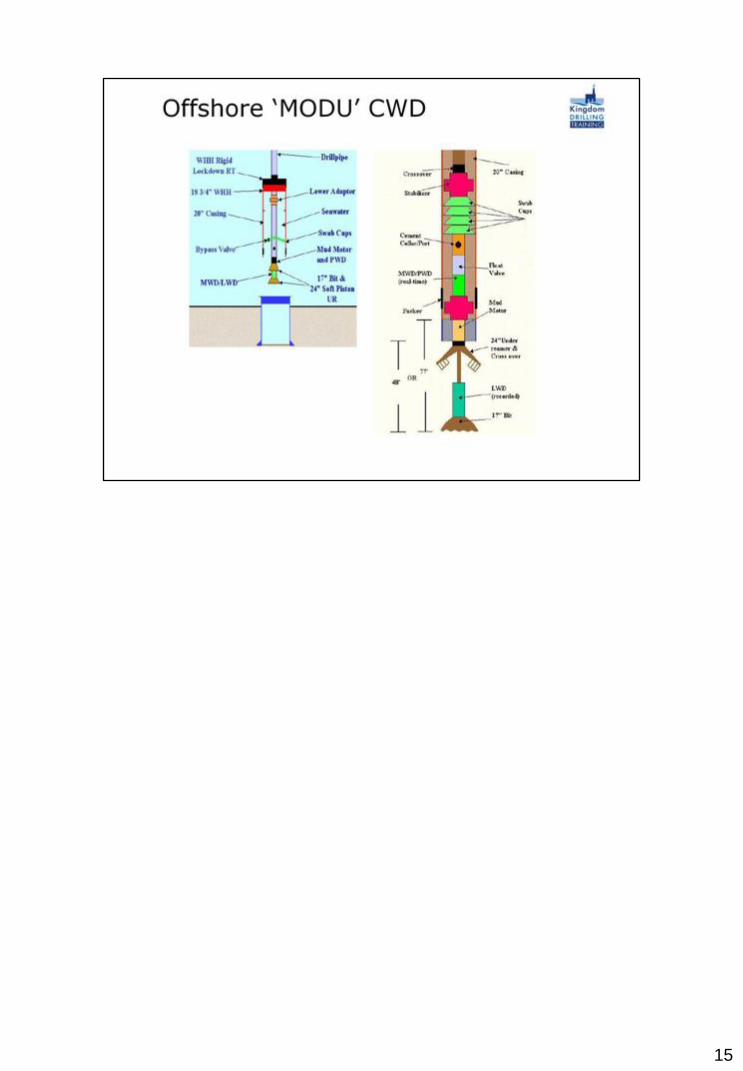
‘Casing While Drilling’ technology, is related to drilling using ‘Casing’ instead of ‘Drill Pipe’. The casing transmits the required mechanical cutting forces and the hydraulic energy to the rock, while simultaneously casing the wellbore. The earliest know instance of casing drilling was in Russia in the 1930’s.* According to Tesco Corp, over 1000 sections and 3 million feet have been drilled with casing by Dec 2008.** There are two techniques available in the drilling industry for casing while drilling.
13

One major problem with casing-while-drilling technology is that no open-hole logging can be performed. Once drilled the hole is cased and no open-hole sections remains. This can be disadvantageous when reservoir sections are to be drilled with casing. But the advantage of being able to case a section of unconsolidated reservoir outweighs the lack of open-hole logging. Most of the formation evaluation can also be preformed through the casing.
14
15
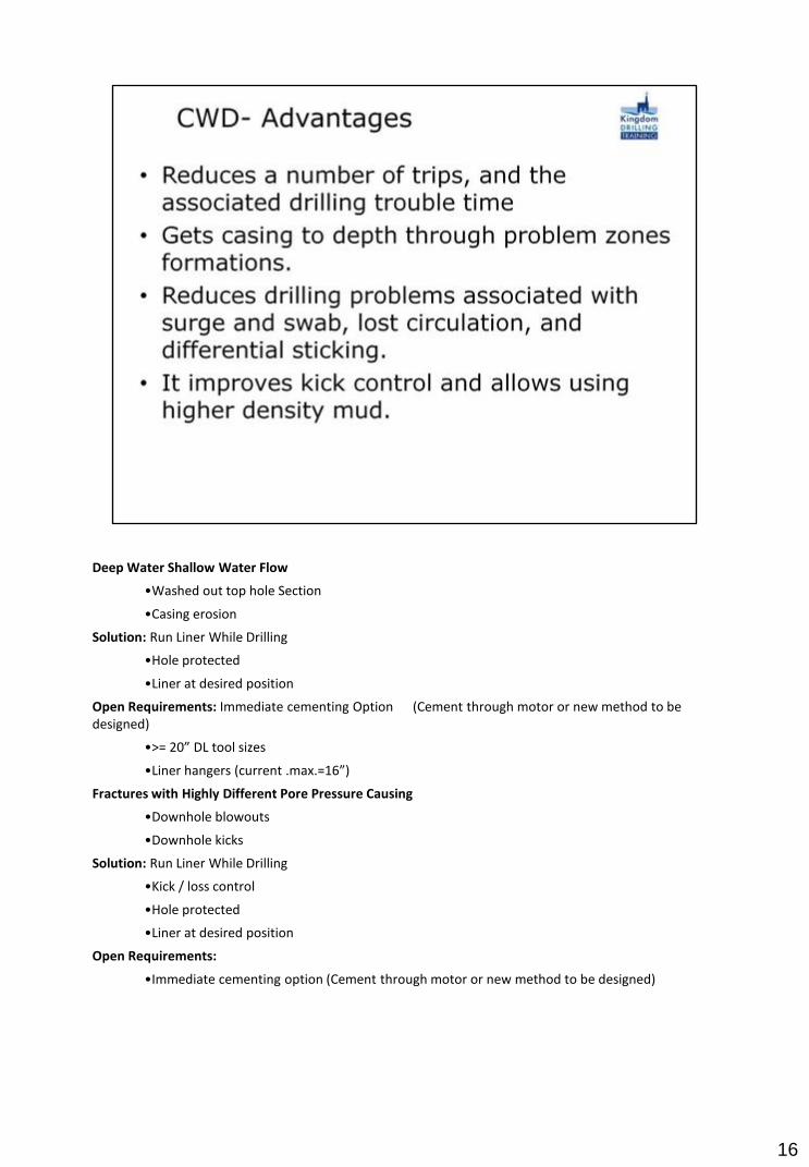
Deep Water Shallow Water Flow
•Washed out top hole Section
•Casing erosion
Solution: Run Liner While Drilling
•Hole protected
•Liner at desired position
Open Requirements: Immediate cementing Option (Cement through motor or new method to be designed)
•>= 20” DL tool sizes
•Liner hangers (current .max.=16”)
Fractures with Highly Different Pore Pressure Causing
•Downhole blowouts
•Downhole kicks
Solution: Run Liner While Drilling
•Kick / loss control
•Hole protected
•Liner at desired position
Open Requirements:
•Immediate cementing option (Cement through motor or new method to be designed)
16

17

The candidate selection software draws from several databases of MPD wells drilled.
The first, developed by Signa, breaks the MPD well data down by MPD variation, i.e., constant bottom hole pressure, dual gradient, pressure mud cap control drilling and so on.
At Balance with Smith developed a second database that details wells by rig type.
Finally, the database from Secure Drilling (now part of Weatherford International) also analyses rig type, as well as project type (development, exploratory, HP, HPHT, etc).
18
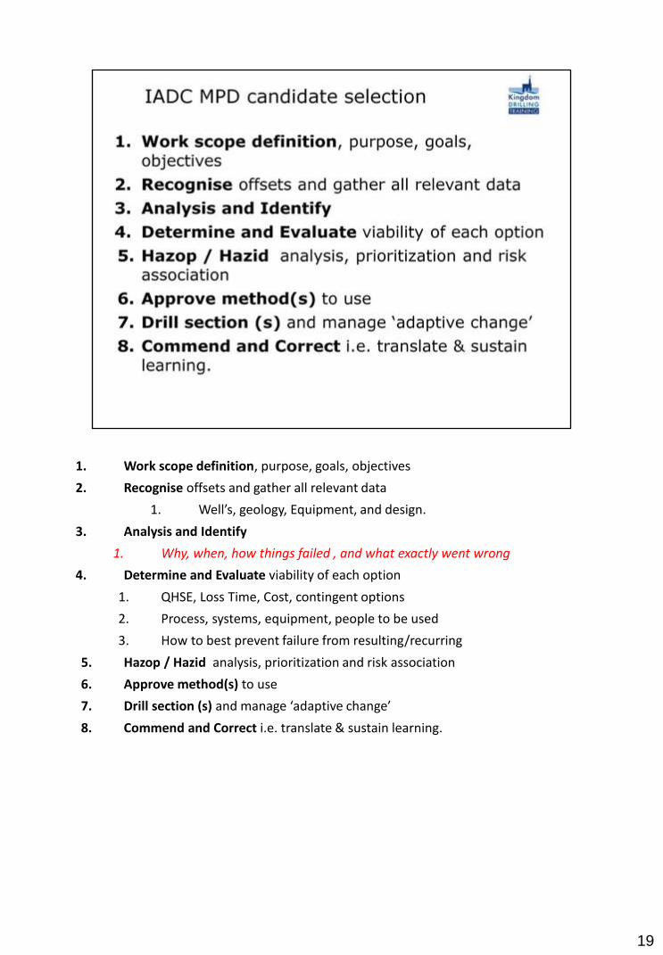
1. Work scope definition, purpose, goals, objectives
2. Recognise offsets and gather all relevant data
1. Well’s, geology, Equipment, and design.
3. Analysis and Identify
1. Why, when, how things failed , and what exactly went wrong
4. Determine and Evaluate viability of each option
1. QHSE, Loss Time, Cost, contingent options
2. Process, systems, equipment, people to be used
3. How to best prevent failure from resulting/recurring
5. Hazop / Hazid analysis, prioritization and risk association
6. Approve method(s) to use
7. Drill section (s) and manage ‘adaptive change’
8. Commend and Correct i.e. translate & sustain learning.
19

20

21

22

23

24

25
26
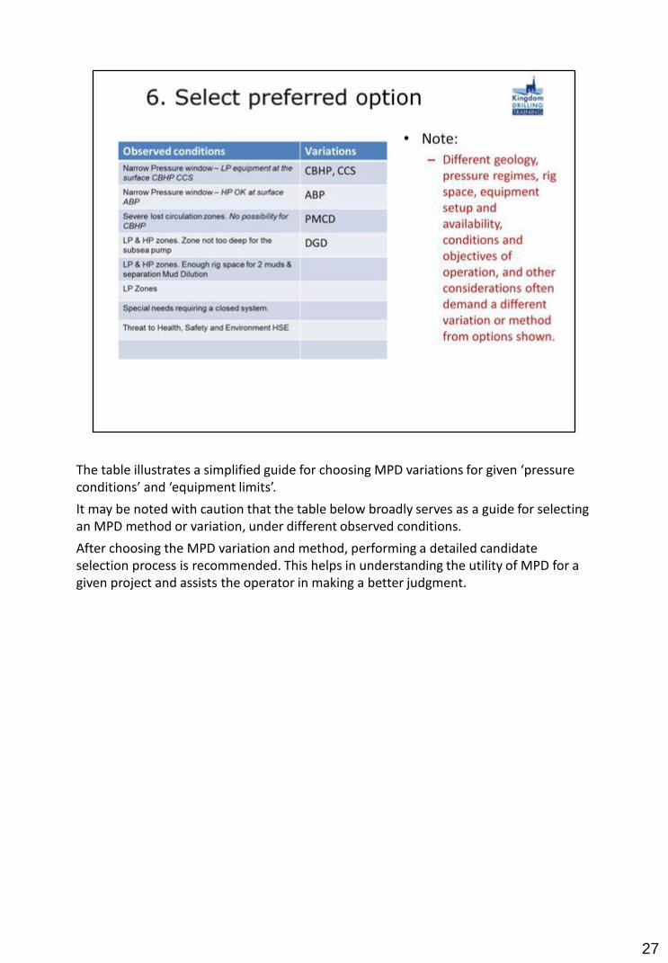
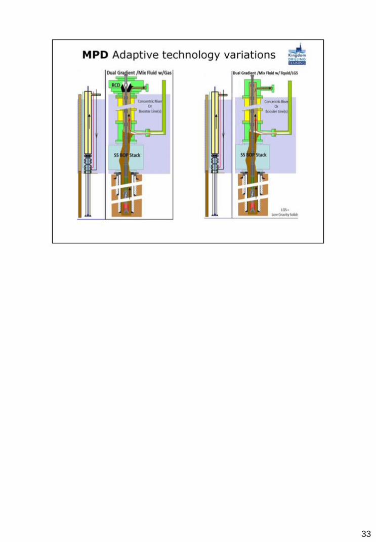
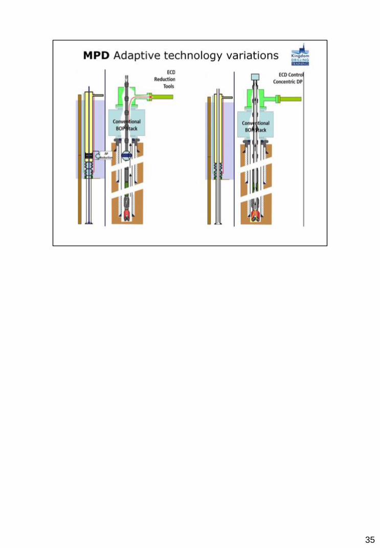
The table illustrates a simplified guide for choosing MPD variations for given ‘pressure conditions’ and ‘equipment limits’.
It may be noted with caution that the table below broadly serves as a guide for selecting an MPD method or variation, under different observed conditions.
After choosing the MPD variation and method, performing a detailed candidate selection process is recommended. This helps in understanding the utility of MPD for a given project and assists the operator in making a better judgment.
27

28

29

30

31
32
33

34
35
36
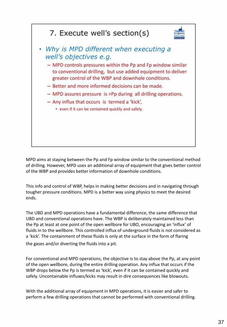
MPD aims at staying between the Pp and Fp window similar to the conventional method of drilling. However, MPD uses an additional array of equipment that gives better control of the WBP and provides better information of downhole conditions.
This info and control of WBP, helps in making better decisions and in navigating through tougher pressure conditions. MPD is a better way using physics to meet the desired ends.
The UBD and MPD operations have a fundamental difference, the same difference that UBD and conventional operations have. The WBP is deliberately maintained less than the Pp at least at one point of the open wellbore for UBO, encouraging an ‘influx’ of fluids in to the wellbore. This controlled influx of underground fluids is not considered as a ‘kick’. The containment of these fluids is only at the surface in the form of flaring
the gases and/or diverting the fluids into a pit.
For conventional and MPD operations, the objective is to stay above the Pp, at any point of the open wellbore, during the entire drilling operation. Any influx that occurs if the WBP drops below the Pp is termed as ‘kick’, even if it can be contained quickly and safely. Uncontainable influxes/kicks may result in dire consequences like blowouts.
With the additional array of equipment in MPD operations, it is easier and safer to perform a few drilling operations that cannot be performed with conventional drilling.
37

38

39
40

41