Introduction to multimedia. Analog/digital representation of multimedia data.
18
Introduction to multimedia. Analog/digital representation of multimedia data
-
Upload
damon-garrett -
Category
Documents
-
view
294 -
download
3
Transcript of Introduction to multimedia. Analog/digital representation of multimedia data.

Introduction to multimedia. Analog/digital
representation of multimedia data

Contents
What is multimedia? Analog representation of audio data Analog representation of video data Digital representation of audio-video data Color spaces for images

What is multimedia?
media = text, graphics, still images, voice, sound
multimedia = a combination of several media types; ex. audio stream, moving images (movie/video), audio+video, animation, interactive animation
multimedia issues followed in this course: storage of multimedia content – containers, codecs transmission of multimedia content – multimedia
streaming presentation/delivery of multimedia content –
players, codecs, continuous delivery

Multimedia applications
video on demand video broadcasting live broadcasting videoconferencing multimedia presentations on the web multimedia databases Peer-2-Peer video streaming Internet Television etc.

Analog signal (audio, video) representation
Analog signal - continuous signal for which the time varying feature (variable) of the signal is a representation of some other time varying quantity, i.e., analogous to another time varying signal.
ex.: in sound recording, fluctuations in air pressure representing the actual sound “is analogus” to the variations induced by a vibrating diaphragm in the electrical current/voltage produced by the coil/condensor in an electromagnetic microphone; in radio modulation of a sinusoidal carrier wave (e.g. amplitude modulation – AM, frequency modulation – FM)
advantages: has the potential of infinite resolution of the signal (high
density) processing is simple
disadvantages: noise – as the signal is copied and re-copied or transmitted over
long distances random variations occur impossible to recover from noise/distortion
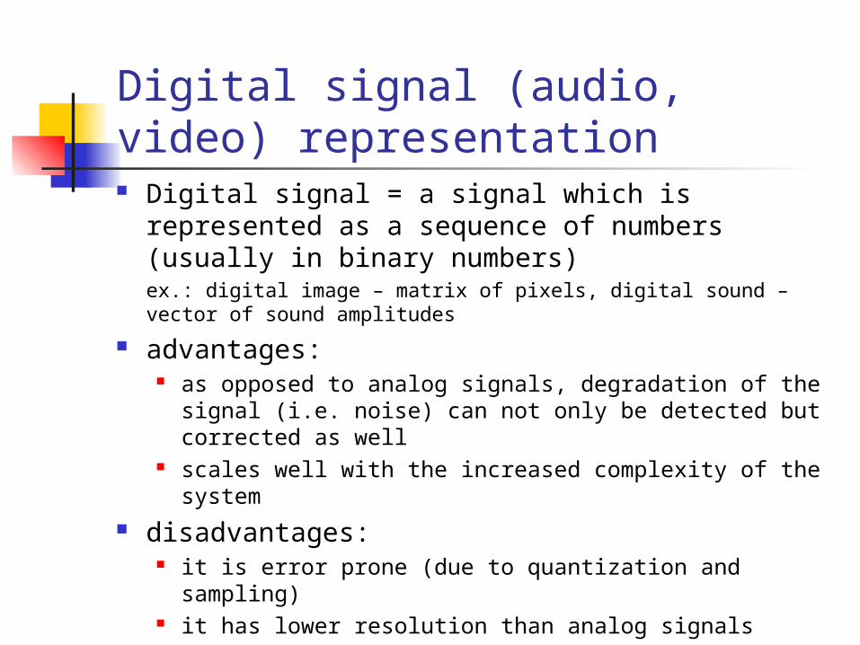
Digital signal (audio, video) representation Digital signal = a signal which is represented as
a sequence of numbers (usually in binary numbers)ex.: digital image – matrix of pixels, digital sound – vector of sound amplitudes
advantages: as opposed to analog signals, degradation of the signal
(i.e. noise) can not only be detected but corrected as well
scales well with the increased complexity of the system
disadvantages: it is error prone (due to quantization and sampling) it has lower resolution than analog signals

Analog-to-digital signal conversion
converting a continuous analog signal into a discrete digital signal has 2 subprocesses:
1. sampling - conversion of a continuous-space/time (audio, video) signal into a discrete-space/time (audio, video) signal
2. quantization - converting a continuous-valued (audio, video) signal that has a continuous range (set of values that it can take) of intensities and/or colors into a discrete-valued (audio, video) signal that has a discrete range of intensities and/or colors; this is usually done by rounding, truncation or other irreversible non-linear process of information destruction

Sound basics Audio (sound) wave
one-dimensional acoustic pressure wave causes vibration in the eardrum or in a microphone
Frequency range of human ear 20 – 20.000 Hz (20 KHz) perception nearly logarithmic, relation of amplitudes A
and B is expressed as dB = 20 log10 (A/B)
very low pressure (20 µPascal) 0 dB
conversation 50-60 dB
heavy traffic 80 dB
rock band 120 dB
pain threshold 130 dB

Analog representation of sound in analog representation, the sound (variations of
air pressure) is made analogus to the variations in the conveying medium properties (e.g. electrical current/voltage, electromagnetic properties) - the variable property of the medium is modulated by the signal
Ex. of medium properties that are modified: the intensity/voltage of the current generated by a coil in a microphone, the magnetization of magnetic tape or the deviation (or displacement) of the groove of a gramophone disc from a smooth, flat spiral track.
examples of analog sound representation: cassete tapes vinyl records FM and AM radio transmissions

Analog-to-digital conversion of sound Sampling of the audio wave in every T secs
If the sound wave is a linear superposition of noiseless sine waves, with a maximum frequency f :
Sampling rate = 2f, more is useless: Nyquist theorem E.g. CDs are sampled with 44.1 KHz ≈ 2 * 20 KHz Channels with noise (Shannon thereom)
Sampling rate = Bandwidth * log2 (1+Signal/Noise)
Quantization Precision of the digital sample depends on the number
of bits Quantization noise - Error due to finite number of
bits/sample
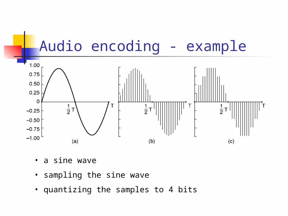
Audio encoding - example
• a sine wave
• sampling the sine wave
• quantizing the samples to 4 bits
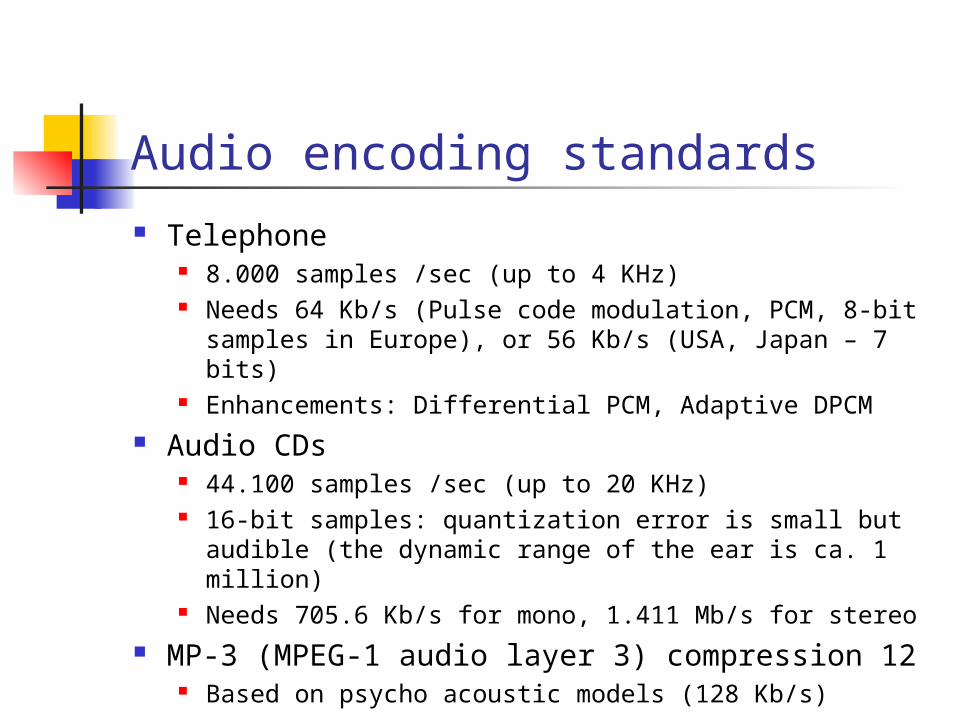
Audio encoding standards
Telephone 8.000 samples /sec (up to 4 KHz) Needs 64 Kb/s (Pulse code modulation, PCM, 8-bit
samples in Europe), or 56 Kb/s (USA, Japan – 7 bits) Enhancements: Differential PCM, Adaptive DPCM
Audio CDs 44.100 samples /sec (up to 20 KHz) 16-bit samples: quantization error is small but
audible (the dynamic range of the ear is ca. 1 million) Needs 705.6 Kb/s for mono, 1.411 Mb/s for stereo
MP-3 (MPEG-1 audio layer 3) compression 12 Based on psycho acoustic models (128 Kb/s)

Analog video signal
is continuous in both the space and time dimensions, since the radiation flux that is incident on a video sensor is continuous at normal scales of observation
when viewed on display monitors is not truly analog, since it is sampled along one space dimension and along the time dimension
practically, TV sets represent video as one-dimensional electrical signal V(t)

Analog video signal (2)
a composite video signal:

Analog video signal (3)
formation of images in a CRT (Cathodic-Ray Tube):

Analog video - basics
Sequence of images flashing faster than 50/sec Makes the impression of continuous movie
TV (black-and-white) An electron beam scans rapidly the image From left to right and from top to bottom At the end of the scan (a frame) the scan retraces NTSC 525 scan lines (483 effective), 30 frames/sec PAL and SECAM: 625 lines (576), 25 frames/sec 25 frames/s produce smooth motion, but flicker Interlacing solves this 50 half frames (fields) / sec Non interlaced: progressive scanning
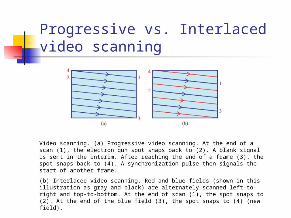
Progressive vs. Interlaced video scanning
Video scanning. (a) Progressive video scanning. At the end of a scan (1), the electron gun spot snaps back to (2). A blank signal is sent in the interim. After reaching the end of a frame (3), the spot snaps back to (4). A synchronization pulse then signals the start of another frame.
(b) Interlaced video scanning. Red and blue fields (shown in this illustration as gray and black) are alternately scanned left-to-right and top-to-bottom. At the end of scan (1), the spot snaps to (2). At the end of the blue field (3), the spot snaps to (4) (new field).

Digital video signal
a digital video is an array with 3-dimensional (space-time) components