Introduction to Verilogece.uprm.edu/~mtoledo/4205/verilog/verilog.pdf · Gate !level modeling ¥...
34
Introduction to Verilog INEL 4205 ! Logic Circuits M. Toledo ! Spring 2008
Transcript of Introduction to Verilogece.uprm.edu/~mtoledo/4205/verilog/verilog.pdf · Gate !level modeling ¥...
Introduction to Verilog
INEL 4205 ! Logic CircuitsM. Toledo ! Spring 2008
Hardware description languages "HDL#
• High!level program!like description of logic circuit
• Developed for circuit simulation, now also used to synthesize circuits for ASIC’s and FPGA’s
• Two main hdl’s used today
• VHDL ! ADA!like synTax;
• Verilog ! C!like syntax;

Verilog
• Basic units: modul"
• normally describe a single piece of hardware
• has declarations that describe names & types of module’s inputs & outputs
module fourbitadder" X, Y, S, C# ; // c++ style remarksinput $3:0% X, Y; // four!bit input !ectors
output reg $3:0% S;// 4!bit sum vectoroutput reg C ; // & one!bit carry
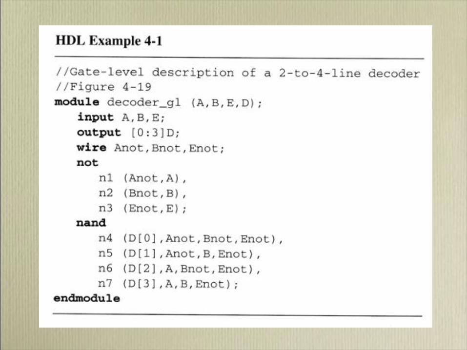
Gate!level modeling
• Textual description of schematic diagram
• Uses keywords like and, nand, or, nor, xor, xnor, not,
buf
• Four!level logic: 0,1, high!impedance "z#, unknown "x#
• Use `timescale <reference_time_unit>/
<time_precision> to change the reference time scale and precision of a simulation. Example: `timescale 1ns/1p

Modules and testing
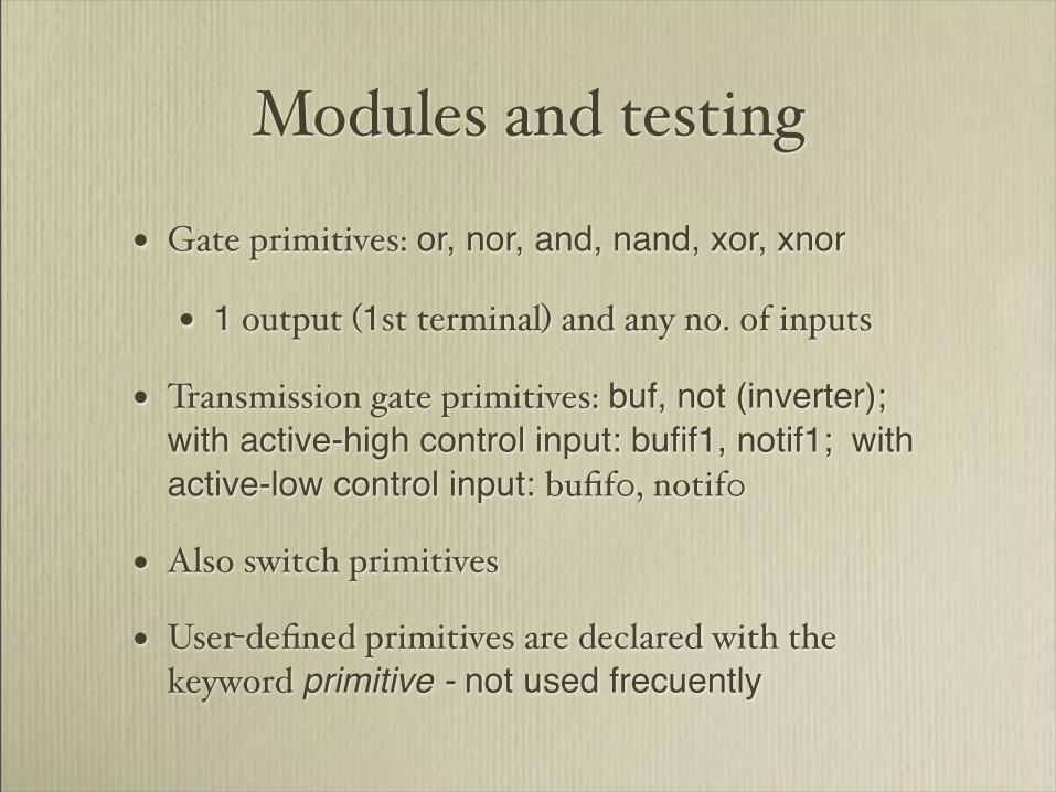
• Gate primitives: or, nor, and, nand, xor, xnor
• 1 output "1st terminal# and any no. of inputs
• Transmission gate primitives: buf, not (inverter);
with active-high control input: bufif1, notif1; with
active-low control input: bufif0, notif0
• Also switch primitives
• User!defined primitives are declared with the keyword primitive - not used frecuently

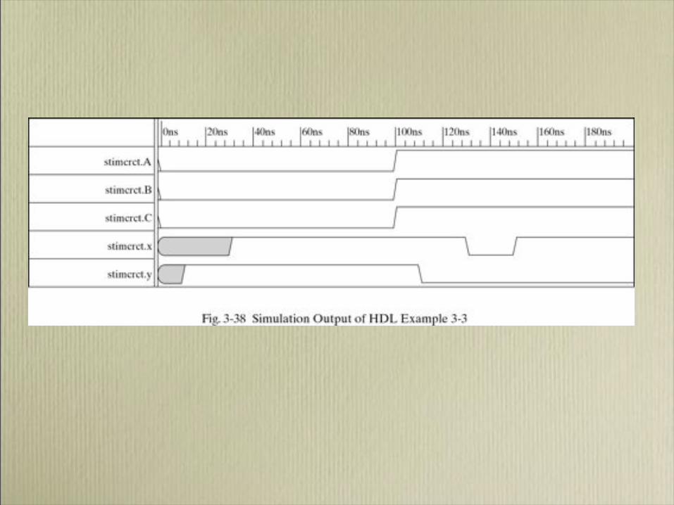
Simulations are specified in a testbench which is a module

Data Types
• Nets ! represent structural connections
• “wire” is the most common net type
• reg ! represent variables used to store data
• store the last value assigned to them until another assignment statement changes their value

Port Connection Rules• Inputs : internally must always be type net,
externally the inputs can be connected to
variable reg or net (wire) type.
• Outputs : internally can be type net or reg,
externally the outputs must be connected to a
variable net type.
• Inouts : internally or externally must always
be type net, can only be connected to a
variable net type.
• implicit type (not explicitly declared) is one-bit
wire


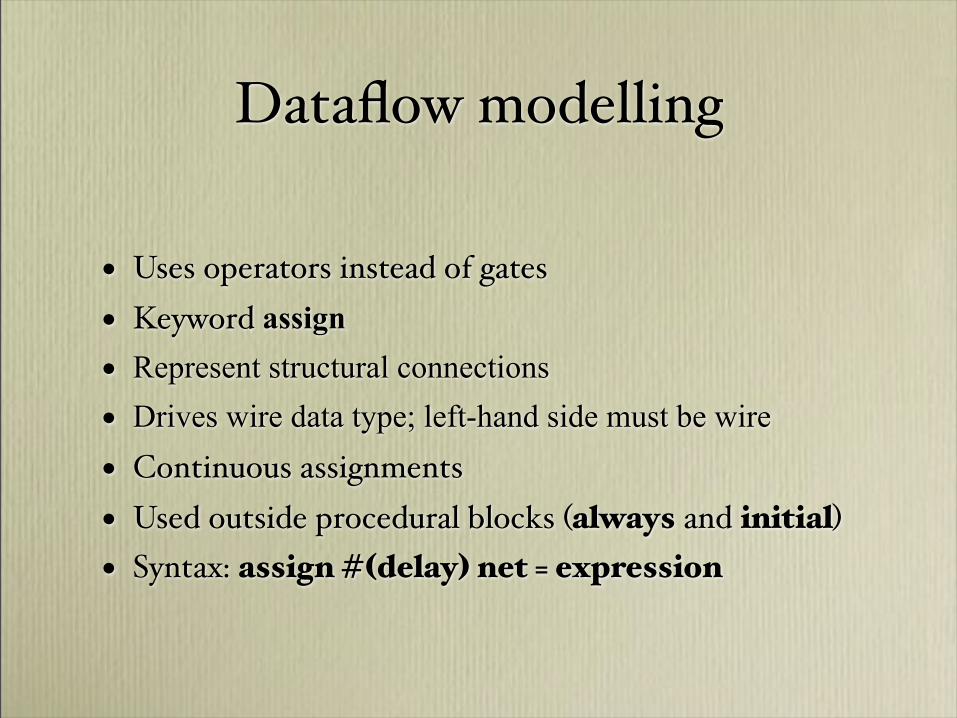
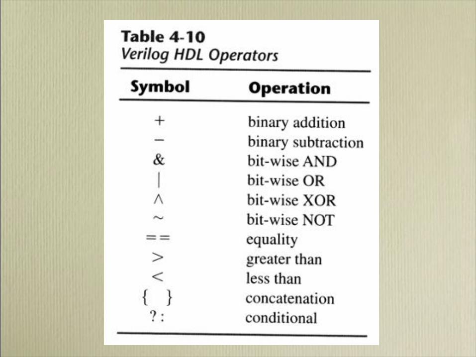
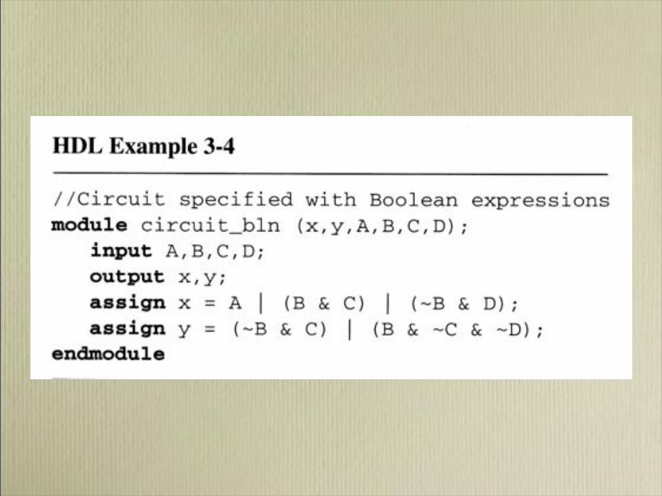
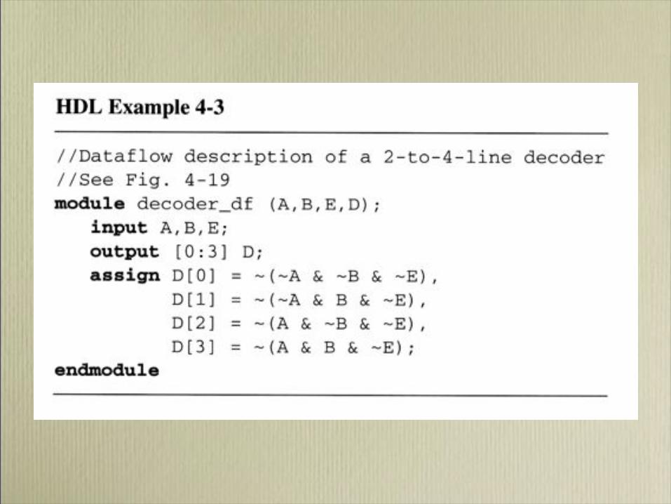
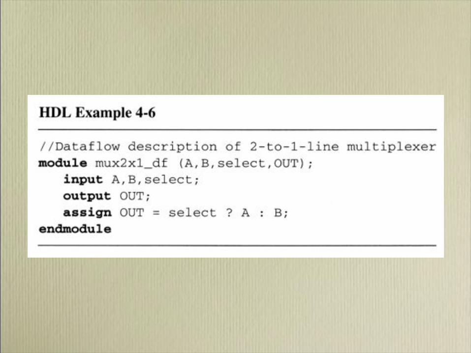
Dataflow modelling
• Uses operators instead of gates
• Keyword assign
• Represent structural connections
• Drives wire data type; left-hand side must be wire
• Continuous assignments
• Used outside procedural blocks "always and initial#
• Syntax: assign #!delay" net = expression
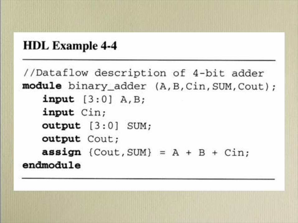

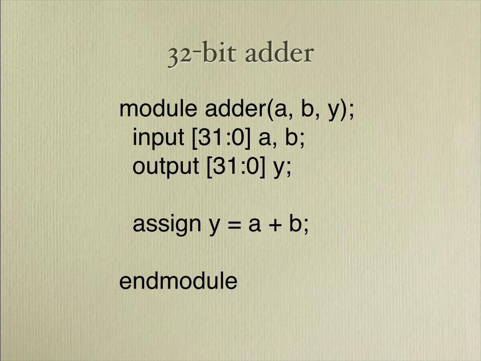
32!bit adder
module adder(a, b, y);
input [31:0] a, b;
output [31:0] y;
assign y = a + b;
endmodule


Behavioral Model
• Declared using keywords
– initial : Executes following block once
– always: Executes repeatedly. Block is reevaluated
only when signals in the header change
• Executes following statement, or block of statements
within begin and end
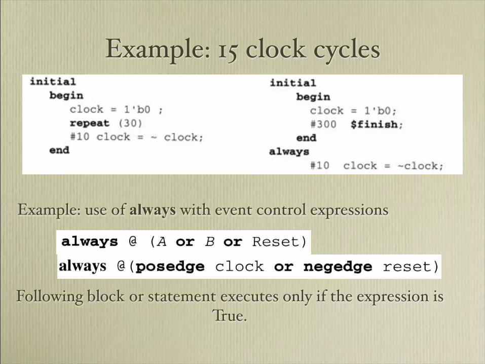
Example: 15 clock cycles
Example: use of always with event control expressions
Following block or statement executes only if the expression is True.
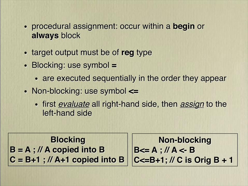
• procedural assignment: occur within a begin or always block
• target output must be of reg type
• Blocking: use symbol =
• are executed sequentially in the order they appear
• Non-blocking: use symbol <=
• first evaluate all right-hand side, then assign to the left-hand side
Blocking
B = A ; // A copied into B
C = B+1 ; // A+1 copied into B
Non-blocking
B<= A!; // A <- B
C<=B+1; // C is Orig B + 1

//HDL Example 5-1
//Description of D latch (See Fig.5-6)
module D_latch (Q,D,control);
output Q;
input D,control;
reg Q;
always @ (control or D)
if (control) Q = D;
//Same as: if (control = 1)
endmodule

//HDL Example 5-2
//D flip-flop
module D_FF (Q,D,CLK);
output Q;
input D,CLK;
reg Q;
always @ (posedge CLK)
Q = D;
endmodule
//D flip-flop with asynchronous reset.
module DFF (Q,D,CLK,RST);
output Q;
input D,CLK,RST;
reg Q;
always @(posedge CLK or negedge RST)
if (~RST) Q = 1'b0; // Same as: if (RST = 0)
else Q = D;
endmodule
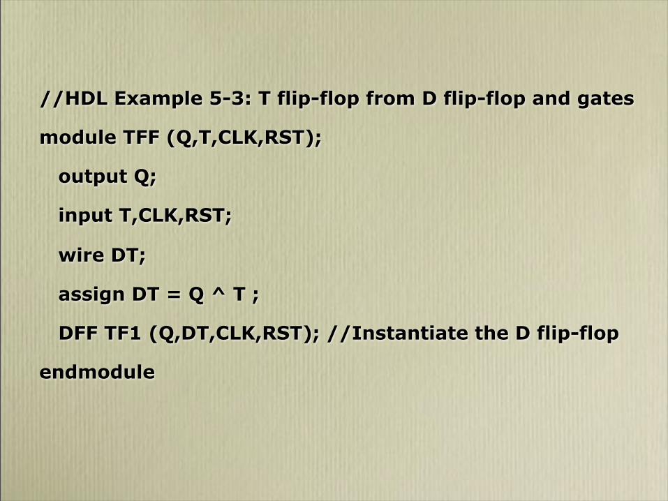
//HDL Example 5-3: T flip-flop from D flip-flop and gates
module TFF (Q,T,CLK,RST);
output Q;
input T,CLK,RST;
wire DT;
assign DT = Q ^ T ;
DFF TF1 (Q,DT,CLK,RST); //Instantiate the D flip-flop
endmodule

//HDL Example 5-3: Continuation
//JK flip-flop from D flip-flop and gates
module JKFF (Q,J,K,CLK,RST);
output Q;
input J,K,CLK,RST;
wire JK;
assign JK = (J & ~Q) | (~K & Q);
DFF JK1 (Q,JK,CLK,RST); //Instantiate D FF (prev slide)
endmodule

//HDL Example 5-4
// Functional description of JK flip-flop
module JK_FF (J,K,CLK,Q,Qnot);
output Q,Qnot;
input J,K,CLK;
reg Q;
assign Qnot = ~ Q ;
//HDL Example 5-4 (cont)
always @ (posedge CLK)
case ({J,K})
2'b00: Q = Q;
2'b01: Q = 1'b0;
2'b10: Q = 1'b1;
2'b11: Q = ~ Q;
endcase
endmodule


//HDL Example 5-5: Mealy state diagram (Fig 5-16)
module Mealy_mdl (x,y,CLK,RST);
input x,CLK,RST;
output y;
reg y;
reg [1:0] Prstate, Nxtstate;
parameter S0 = 2'b00, S1 = 2'b01, S2 = 2'b10, S3 = 2'b11;
always @ (posedge CLK or negedge RST)
if (~RST) Prstate = S0; //Initialize to state S0
else Prstate = Nxtstate; //Clock operations
always @ (Prstate or x) //Find next state
case (Prstate)
S0: if (x) Nxtstate = S1;
S1: if (x) Nxtstate = S3;
else Nxtstate = S0;
S2: if (~x)Nxtstate = S0;
S3: if (x) Nxtstate = S2;
else Nxtstate = S0;
endcase
always @ (Prstate or x) //Evaluate output
case (Prstate)
S0: y = 0;
S1: if (x) y = 1'b0; else y = 1'b1;
S2: if (x) y = 1'b0; else y = 1'b1;
S3: if (x) y = 1'b0; else y = 1'b1;
endcase
endmodule

Verilog Problem• Write Verilog gate!level, dataflow and behavioral
descriptions for the following circuits. Test the circuit by writing a testbench module and running a simulation.
• a priority encoder such as the one shown in figure 4.23,
• a four!bit adder!subtractor such as the one shown in figure 4.13, and
• a sequence detector such as the one shown in figure 5.29