iNTRODUCTION TO MICROCONTROLLERS
72
UBC104 Embedded Systems Review: Introduction to Microcontrollers
-
Upload
alok-srivastav -
Category
Documents
-
view
31 -
download
4
description
ABOUT 8051
Transcript of iNTRODUCTION TO MICROCONTROLLERS
UBC104 Embedded Systems
Review: Introduction to Microcontrollers
UBC 104 Embedded Systems 2
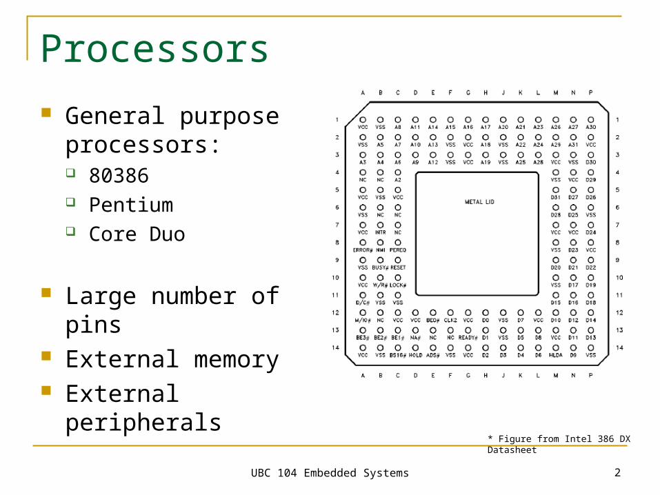
Processors
General purpose processors: 80386 Pentium Core Duo
Large number of pins External memory External peripherals
* Figure from Intel 386 DX Datasheet
UBC 104 Embedded Systems 3
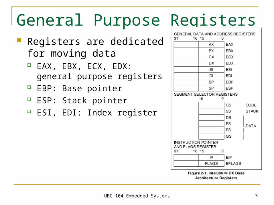
General Purpose Registers Registers are dedicated for
moving data EAX, EBX, ECX, EDX: general
purpose registers EBP: Base pointer ESP: Stack pointer ESI, EDI: Index register
UBC 104 Embedded Systems 4
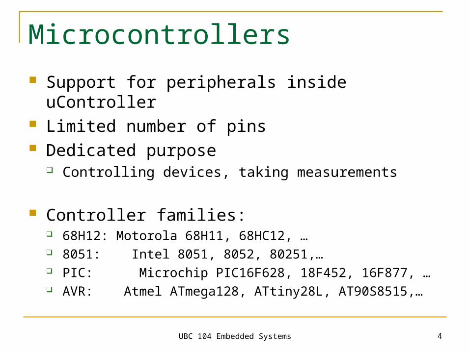
Microcontrollers
Support for peripherals inside uController Limited number of pins Dedicated purpose
Controlling devices, taking measurements
Controller families: 68H12: Motorola 68H11, 68HC12, … 8051: Intel 8051, 8052, 80251,… PIC: Microchip PIC16F628, 18F452, 16F877, … AVR: Atmel ATmega128, ATtiny28L, AT90S8515,…
UBC 104 Embedded Systems 5
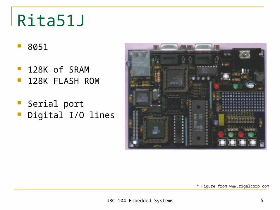
Rita51J 8051
128K of SRAM 128K FLASH ROM
Serial port Digital I/O lines
* Figure from www.rigelcorp.com
UBC 104 Embedded Systems 6
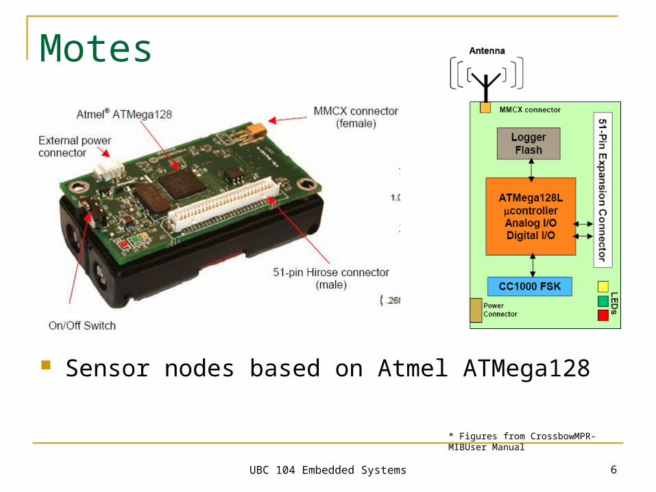
Motes
Sensor nodes based on Atmel ATMega128
* Figures from CrossbowMPR-MIBUser Manual
UBC 104 Embedded Systems 7
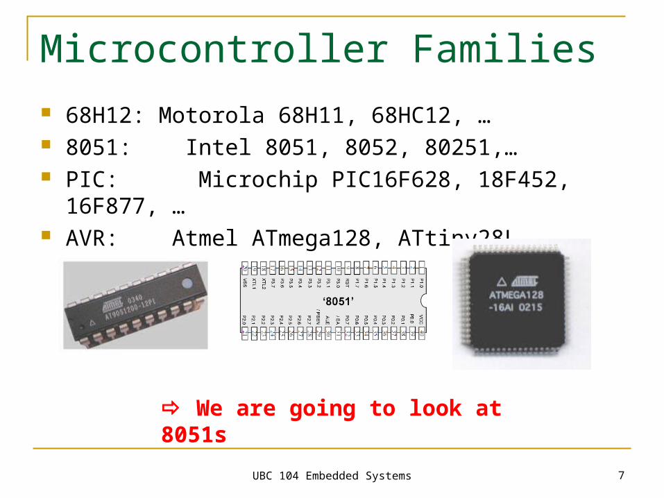
Microcontroller Families 68H12: Motorola 68H11, 68HC12, … 8051: Intel 8051, 8052, 80251,… PIC: Microchip PIC16F628, 18F452, 16F877, … AVR: Atmel ATmega128, ATtiny28L, AT90S8515,…
We are going to look at 8051s
UBC 104 Embedded Systems 8
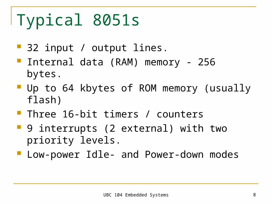
Typical 8051s
32 input / output lines. Internal data (RAM) memory - 256 bytes. Up to 64 kbytes of ROM memory (usually flash) Three 16-bit timers / counters 9 interrupts (2 external) with two priority levels. Low-power Idle- and Power-down modes
UBC 104 Embedded Systems 9
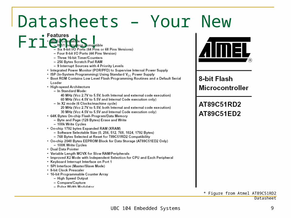
Datasheets – Your New Friends!
* Figure from Atmel AT89C51RD2 Datasheet
UBC 104 Embedded Systems 10
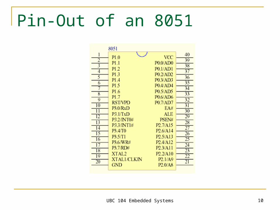
Pin-Out of an 8051
UBC 104 Embedded Systems 11
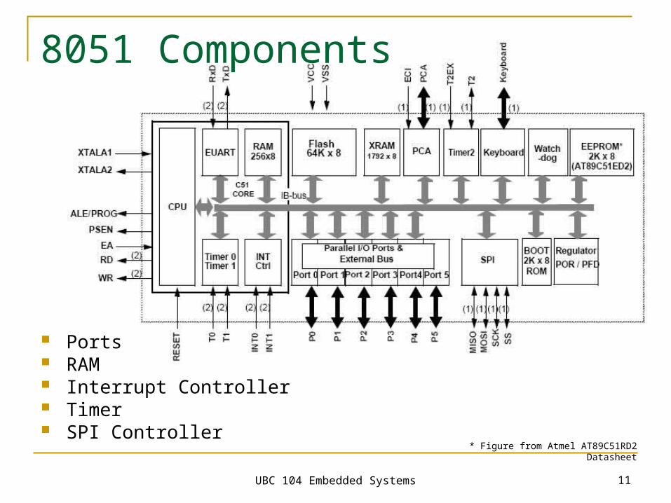
8051 Components
Ports RAM Interrupt Controller Timer SPI Controller
* Figure from Atmel AT89C51RD2 Datasheet
UBC 104 Embedded Systems 12
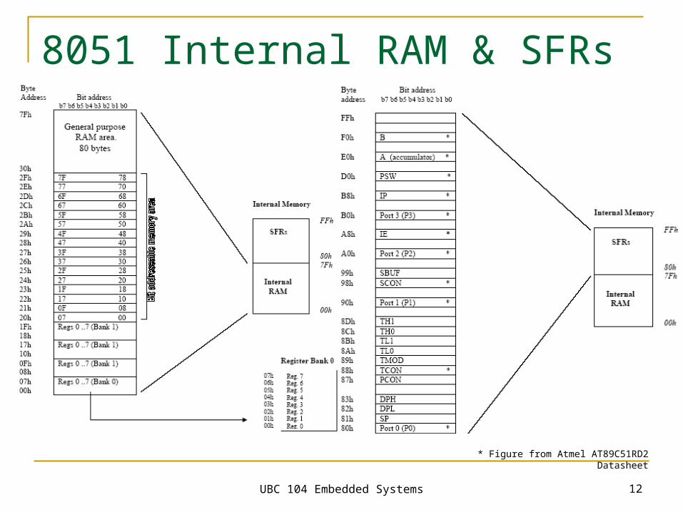
8051 Internal RAM & SFRs
* Figure from Atmel AT89C51RD2 Datasheet
UBC 104 Embedded Systems 13
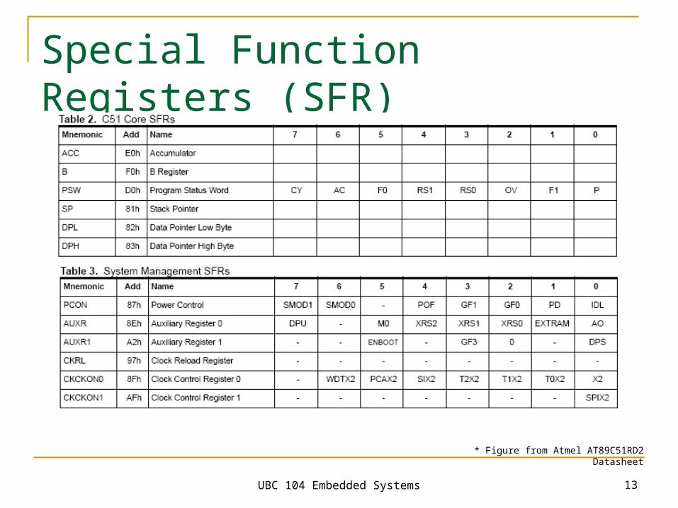
Special Function Registers (SFR)
* Figure from Atmel AT89C51RD2 Datasheet
UBC 104 Embedded Systems 14
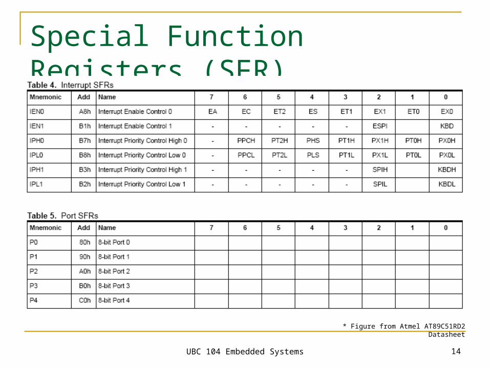
Special Function Registers (SFR)
* Figure from Atmel AT89C51RD2 Datasheet
UBC 104 Embedded Systems 15
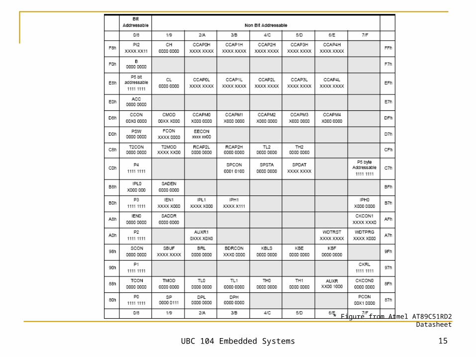
* Figure from Atmel AT89C51RD2 Datasheet
UBC 104 Embedded Systems 16
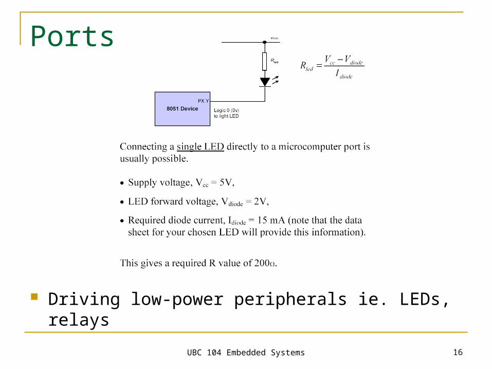
Ports
Driving low-power peripherals ie. LEDs, relays
UBC 104 Embedded Systems 17
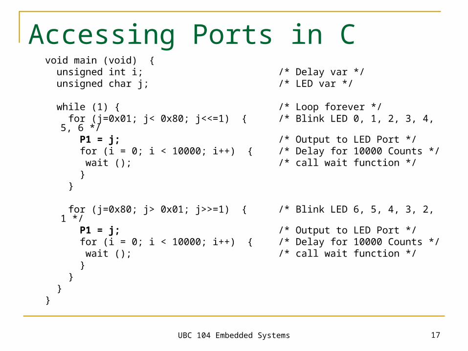
Accessing Ports in Cvoid main (void) { unsigned int i; /* Delay var */ unsigned char j; /* LED var */
while (1) { /* Loop forever */ for (j=0x01; j< 0x80; j<<=1) { /* Blink LED 0, 1, 2, 3, 4, 5, 6 */ P1 = j; /* Output to LED Port */ for (i = 0; i < 10000; i++) { /* Delay for 10000 Counts */ wait (); /* call wait function */ } }
for (j=0x80; j> 0x01; j>>=1) { /* Blink LED 6, 5, 4, 3, 2, 1 */ P1 = j; /* Output to LED Port */ for (i = 0; i < 10000; i++) { /* Delay for 10000 Counts */ wait (); /* call wait function */ } } }}
UBC 104 Embedded Systems 18
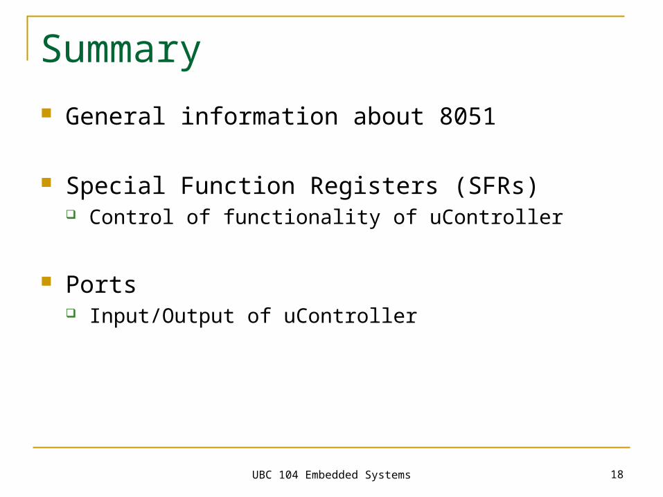
Summary
General information about 8051
Special Function Registers (SFRs) Control of functionality of uController
Ports Input/Output of uController
UBC104 Embedded Systems
Motivation for Next Topics
UBC 104 Embedded Systems 20
Tasks for Microcontroller
Controlling of processes (autonomic) e.g. speed of vehicles, chemical processes
Control of devices through human operator e.g. remote control, etc
UBC 104 Embedded Systems 21
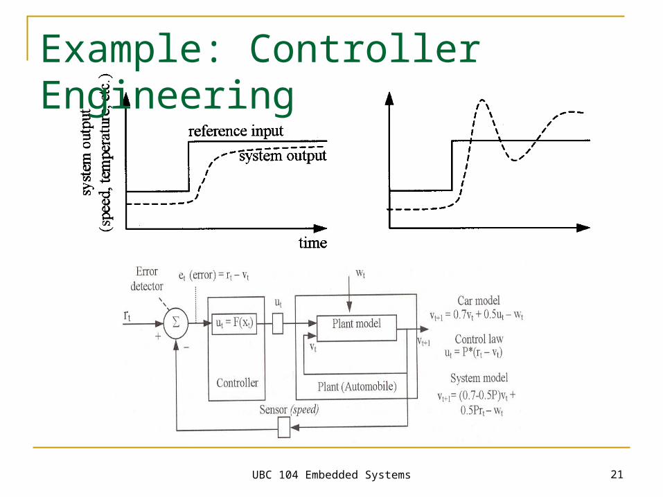
Example: Controller Engineering
UBC 104 Embedded Systems 22
Topics for the Following Lectures Interrupts & Timers Communication Analog to digital (A/D) conversation Pulse Width Modulation
UBC104 Embedded Systems
Interrupts & Timers
UBC 104 Embedded Systems 24
Today’s Topics
Interrupts Timers
UBC 104 Embedded Systems 25
Interrupts
Definition of ‘Interrupt’
Event that disrupts the normal execution of a program and causes the execution of special
instructions
UBC 104 Embedded Systems 26
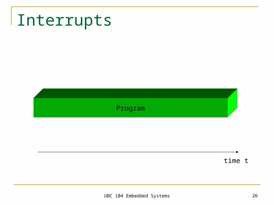
Interrupts
Program
time t
UBC 104 Embedded Systems 27
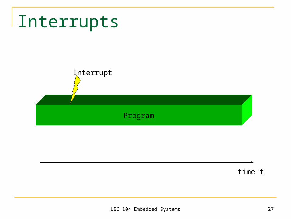
Interrupts
Interrupt
Program
time t
UBC 104 Embedded Systems 28
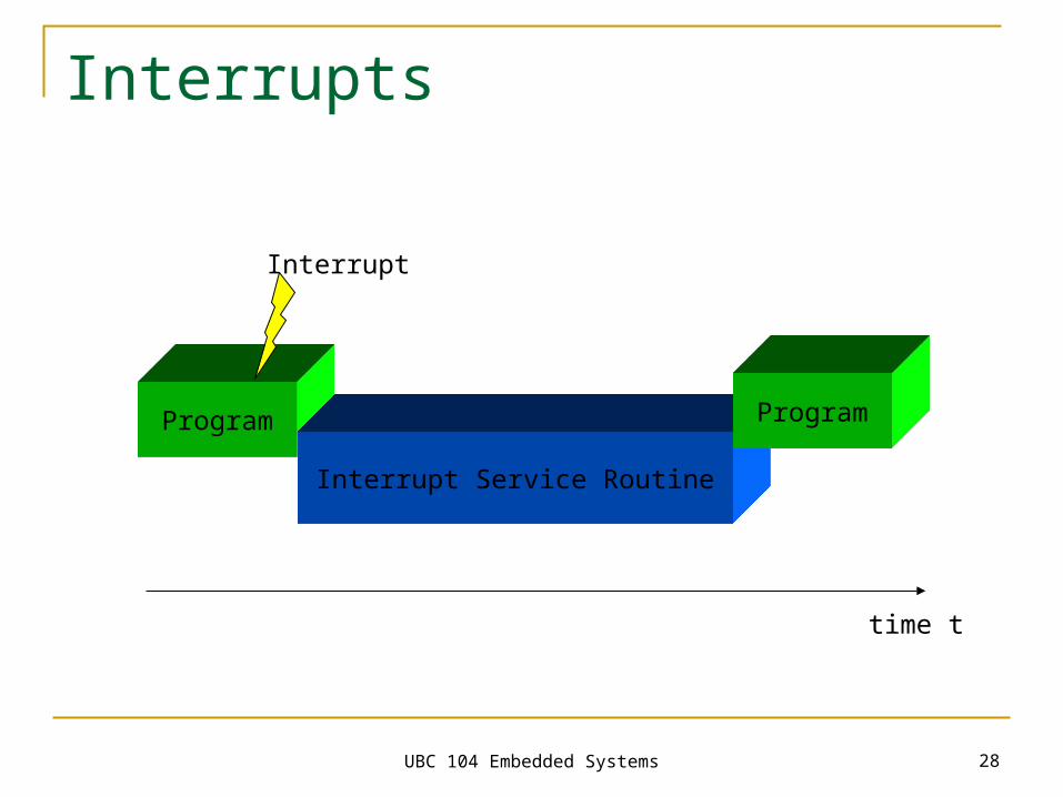
Interrupts
Program
Interrupt Service Routine
Interrupt
Program
time t
UBC 104 Embedded Systems 29
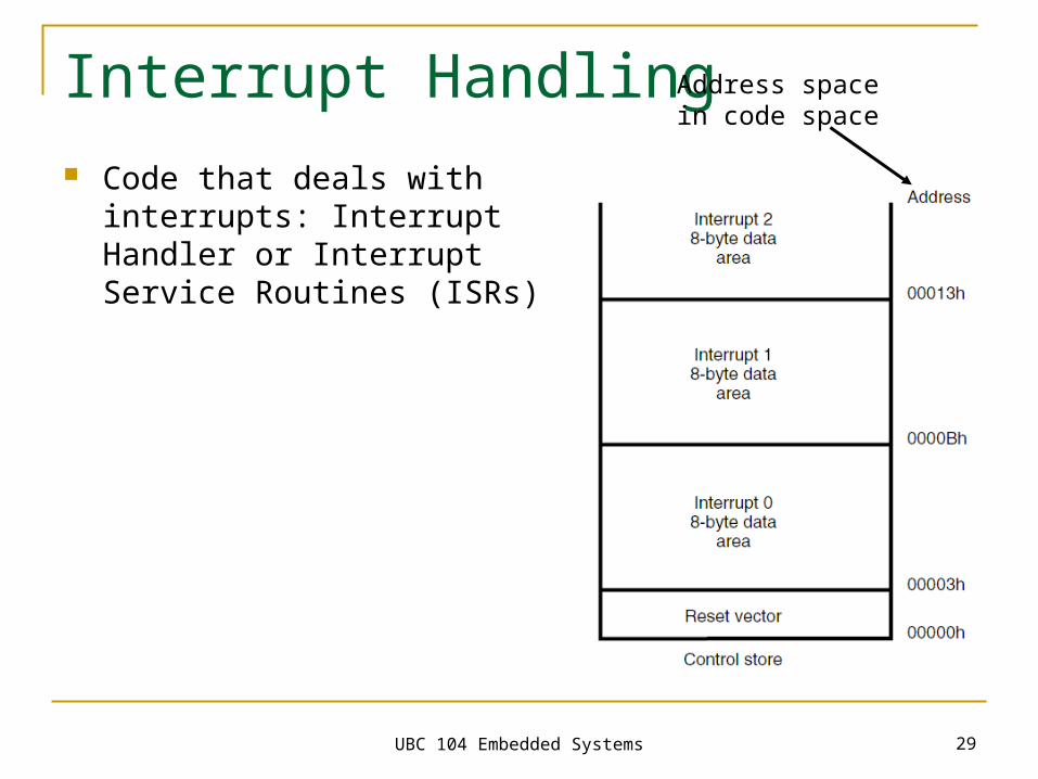
Interrupt Handling Code that deals with interrupts:
Interrupt Handler or Interrupt Service Routines (ISRs)
Address space in code space
UBC 104 Embedded Systems 30
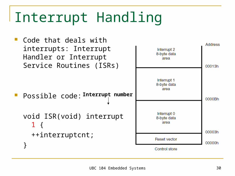
Interrupt Handling Code that deals with interrupts:
Interrupt Handler or Interrupt Service Routines (ISRs)
Possible code:
void ISR(void) interrupt 1 {++interruptcnt;
}
Interrupt number
UBC 104 Embedded Systems 31
Interrupts
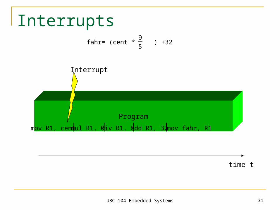
Interrupt
Program
time t
mov R1, cent mul R1, 9 div R1, 5 add R1, 32 mov fahr, R1
fahr= (cent * ) +329
5
UBC 104 Embedded Systems 32
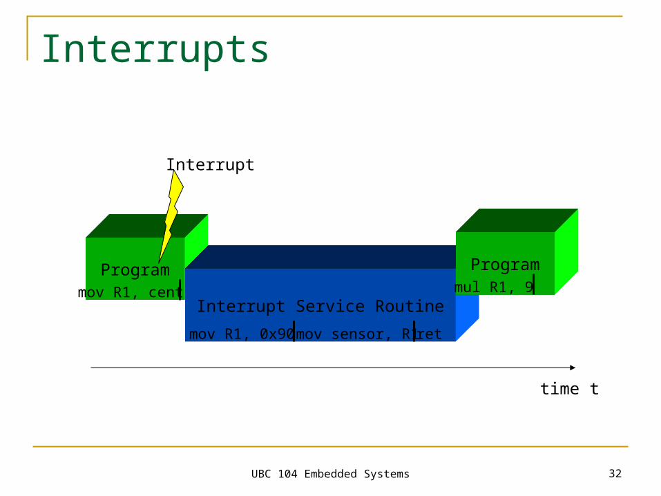
Interrupts
Program
Interrupt Service Routine
Interrupt
Program
time t
mov R1, cent mul R1, 9
mov R1, 0x90 mov sensor, R1 ret

UBC 104 Embedded Systems 33
Interrupts
ProgramSave
Context Interrupt Service Routine
Restore Context
Interrupt
Program
time t
mov R1, cent mul R1, 9
UBC 104 Embedded Systems 34
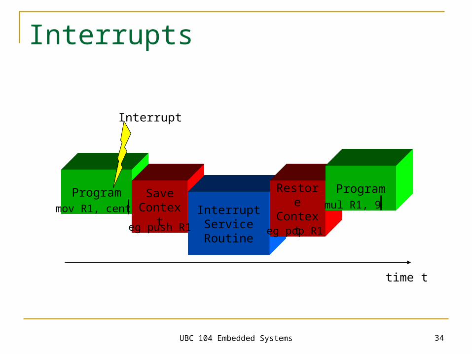
Interrupts
ProgramSave
Context Interrupt Service Routine
Restore Context
Interrupt
Program
time t
mov R1, cent mul R1, 9
eg push R1 eg pop R1
UBC 104 Embedded Systems 35
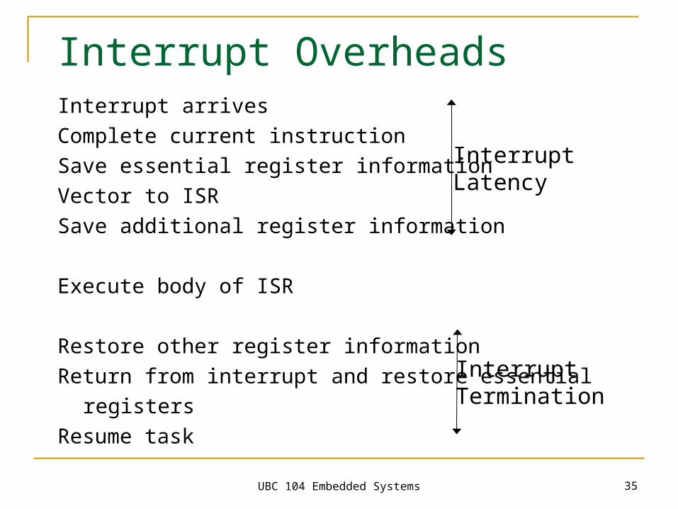
Interrupt Overheads Interrupt arrives
Complete current instruction
Save essential register information
Vector to ISR
Save additional register information
Execute body of ISR
Restore other register information
Return from interrupt and restore essential
registers
Resume task
InterruptLatency
InterruptTermination
UBC 104 Embedded Systems 36
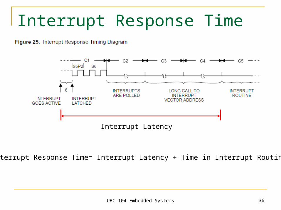
Interrupt Response Time
Interrupt Latency
Interrupt Response Time= Interrupt Latency + Time in Interrupt Routine
UBC 104 Embedded Systems 37
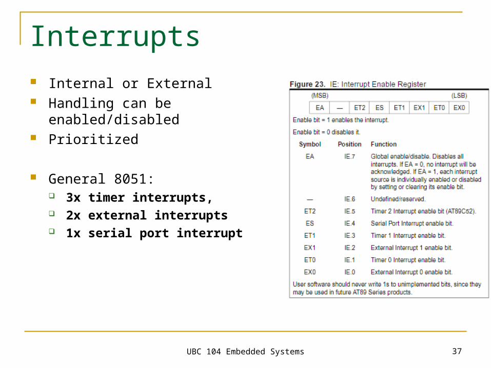
Interrupts Internal or External Handling can be enabled/disabled Prioritized
General 8051: 3x timer interrupts, 2x external interrupts 1x serial port interrupt
UBC 104 Embedded Systems 38
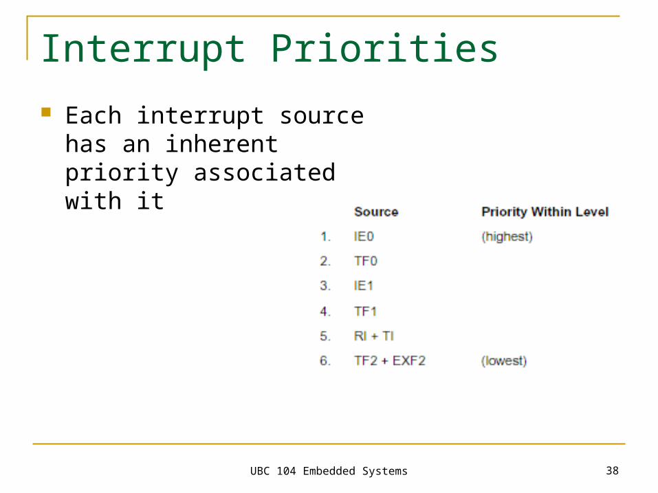
Interrupt Priorities
Each interrupt source has an inherent priority associated with it
UBC 104 Embedded Systems 39
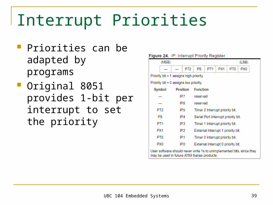
Interrupt Priorities
Priorities can be adapted by programs
Original 8051 provides 1-bit per interrupt to set the priority
UBC 104 Embedded Systems 40
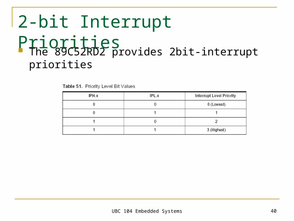
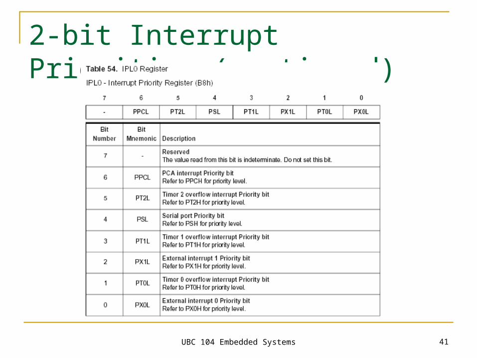
2-bit Interrupt Priorities
The 89C52RD2 provides 2bit-interrupt priorities
UBC 104 Embedded Systems 41
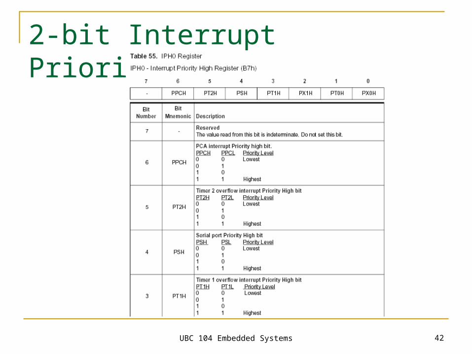
2-bit Interrupt Priorities (continued)
UBC 104 Embedded Systems 42
2-bit Interrupt Priorities (continued)
UBC 104 Embedded Systems 43
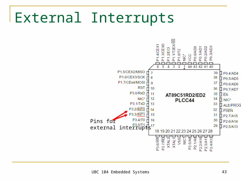
External Interrupts
Pins for external interrupts
UBC 104 Embedded Systems 44
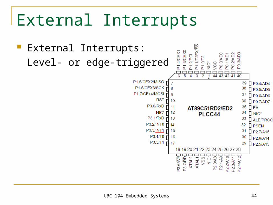
External Interrupts
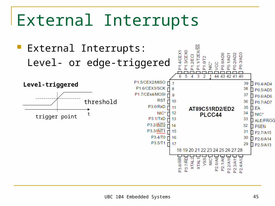
External Interrupts:
Level- or edge-triggered
UBC 104 Embedded Systems 45
External Interrupts
External Interrupts:
Level- or edge-triggered
threshold
Level-triggered
trigger point t
UBC 104 Embedded Systems 46
External Interrupts
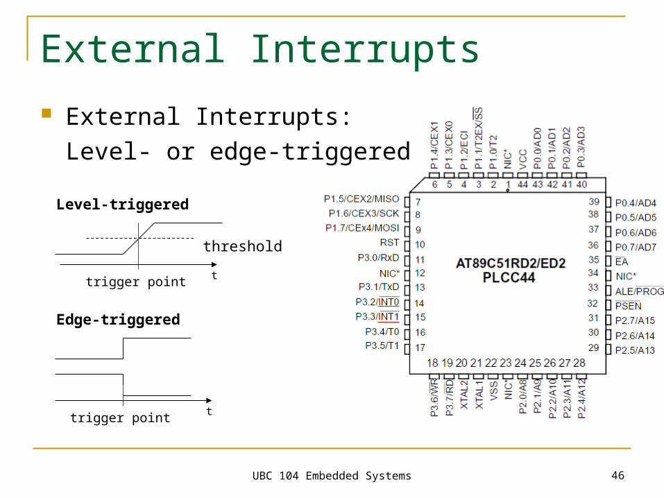
External Interrupts:
Level- or edge-triggered
threshold
Level-triggered
Edge-triggered
trigger point
trigger point
t
t
UBC 104 Embedded Systems 47
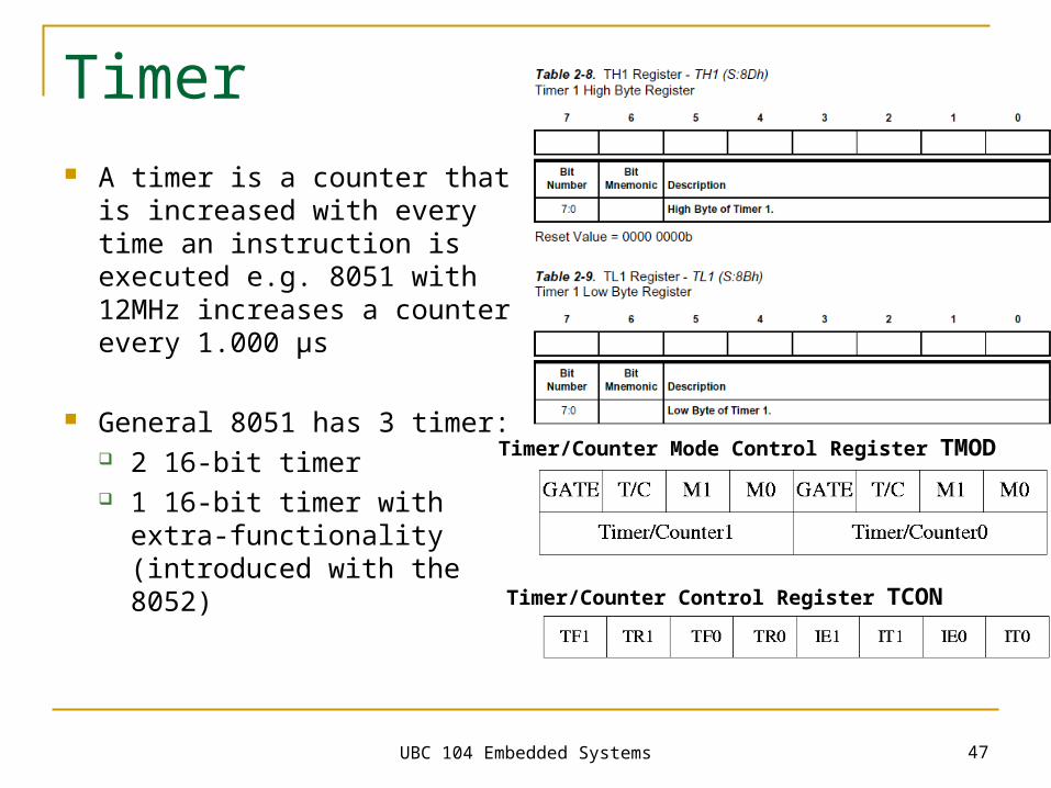
Timer A timer is a counter that is
increased with every time an instruction is executed e.g. 8051 with 12MHz increases a counter every 1.000 µs
General 8051 has 3 timer: 2 16-bit timer 1 16-bit timer with extra-
functionality (introduced with the 8052)
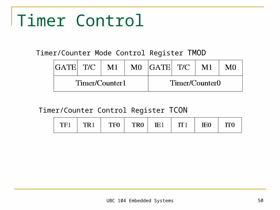
Timer/Counter Mode Control Register TMOD
Timer/Counter Control Register TCON
UBC 104 Embedded Systems 48
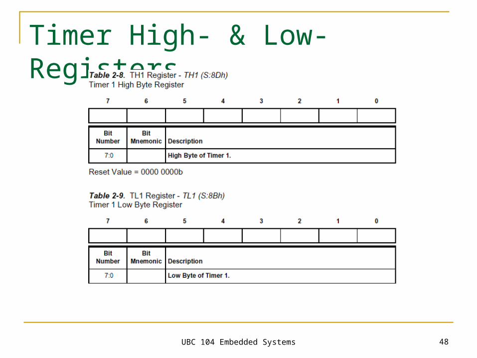
Timer High- & Low-Registers
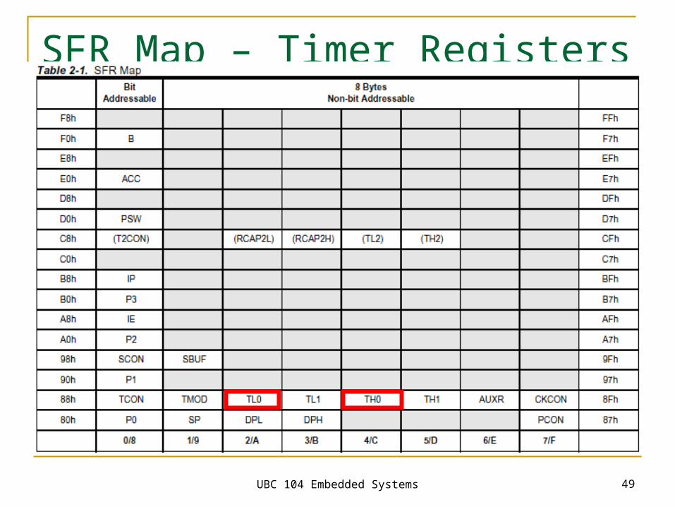
UBC 104 Embedded Systems 49
SFR Map – Timer Registers
UBC 104 Embedded Systems 50
Timer Control
Timer/Counter Mode Control Register TMOD
Timer/Counter Control Register TCON
UBC 104 Embedded Systems 51
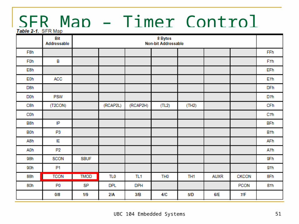
SFR Map – Timer Control
UBC 104 Embedded Systems 52
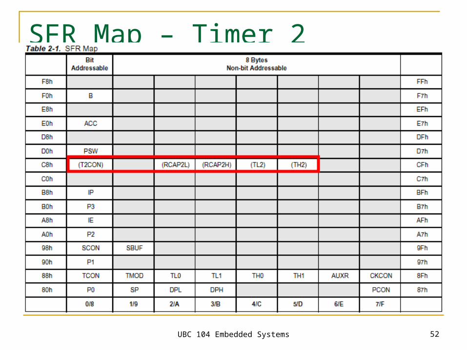
SFR Map – Timer 2
UBC 104 Embedded Systems 53
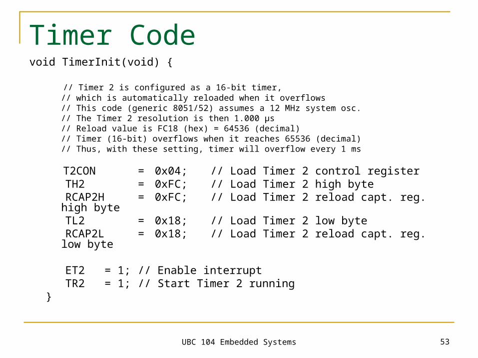
Timer Codevoid TimerInit(void) {
// Timer 2 is configured as a 16-bit timer, // which is automatically reloaded when it overflows // This code (generic 8051/52) assumes a 12 MHz system osc. // The Timer 2 resolution is then 1.000 µs // Reload value is FC18 (hex) = 64536 (decimal) // Timer (16-bit) overflows when it reaches 65536 (decimal) // Thus, with these setting, timer will overflow every 1 ms
T2CON = 0x04; // Load Timer 2 control register TH2 = 0xFC; // Load Timer 2 high byte RCAP2H = 0xFC; // Load Timer 2 reload capt. reg. high
byte TL2 = 0x18; // Load Timer 2 low byte RCAP2L = 0x18; // Load Timer 2 reload capt. reg. low
byte
ET2 = 1; // Enable interrupt TR2 = 1; // Start Timer 2 running}
UBC 104 Embedded Systems 54
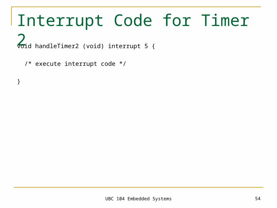
Interrupt Code for Timer 2void handleTimer2 (void) interrupt 5 {
/* execute interrupt code */
}
UBC 104 Embedded Systems 55
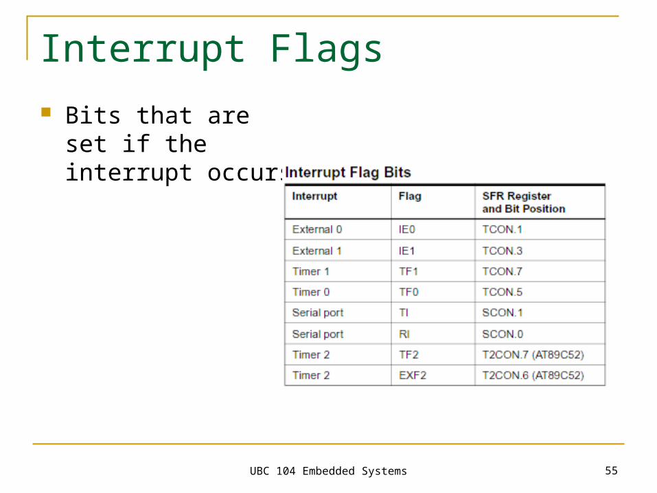
Interrupt Flags
Bits that are set if the interrupt occurs
UBC 104 Embedded Systems 56
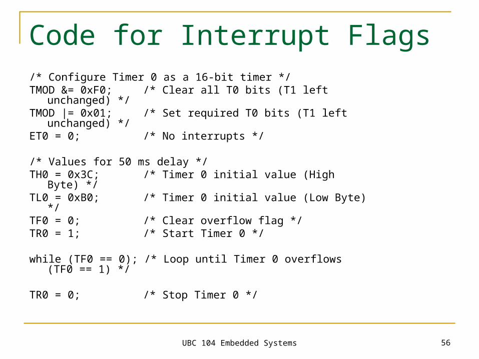
Code for Interrupt Flags/* Configure Timer 0 as a 16-bit timer */TMOD &= 0xF0; /* Clear all T0 bits (T1 left unchanged) */TMOD |= 0x01; /* Set required T0 bits (T1 left unchanged) */ET0 = 0; /* No interrupts */
/* Values for 50 ms delay */TH0 = 0x3C; /* Timer 0 initial value (High Byte) */TL0 = 0xB0; /* Timer 0 initial value (Low Byte) */TF0 = 0; /* Clear overflow flag */TR0 = 1; /* Start Timer 0 */
while (TF0 == 0); /* Loop until Timer 0 overflows (TF0 == 1) */
TR0 = 0; /* Stop Timer 0 */
UBC 104 Embedded Systems 57
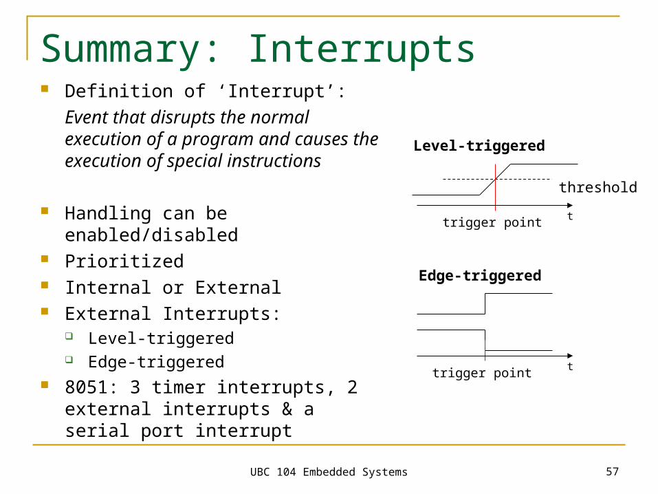
Summary: Interrupts Definition of ‘Interrupt’:
Event that disrupts the normal execution of a program and causes the execution of special instructions
Handling can be enabled/disabled Prioritized Internal or External External Interrupts:
Level-triggered Edge-triggered
8051: 3 timer interrupts, 2 external interrupts & a serial port interrupt
threshold
Level-triggered
Edge-triggered
trigger point
trigger point
t
t
UBC 104 Embedded Systems 58
Real-Time Systems Definition:
A real-time system needs to be
predictable
in terms of values and time
Correctness of an RT system depends on functionality as well as temporal behaviour
UBC 104 Embedded Systems 59
Start
Invoke Scheduler
Set timer
Pick & dispatch a job
Block waiting for timerinterrupt
No
inte
rru
pt
Tim
er
Inte
rru
pt
Se
rvic
e R
ou
time
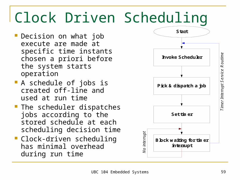
Clock Driven Scheduling Decision on what job execute
are made at specific time instants chosen a priori before the system starts operation
A schedule of jobs is created off-line and used at run time
The scheduler dispatches jobs according to the stored schedule at each scheduling decision time
Clock-driven scheduling has minimal overhead during run time
UBC 104 Embedded Systems 60
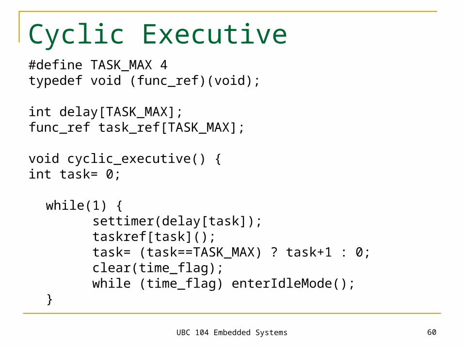
Cyclic Executive#define TASK_MAX 4typedef void (func_ref)(void);
int delay[TASK_MAX];func_ref task_ref[TASK_MAX];
void cyclic_executive() {int task= 0;
while(1) {settimer(delay[task]);taskref[task]();task= (task==TASK_MAX) ? task+1 : 0;clear(time_flag); while (time_flag) enterIdleMode();
}
UBC 104 Embedded Systems 61
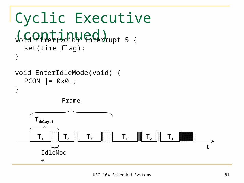
Cyclic Executive (continued)void timer(void) interrupt 5 {
set(time_flag);}
void EnterIdleMode(void) {PCON |= 0x01;
}
T1 T2
Tdelay,1
T3 T1 T2 T3
IdleMode
t
Frame
UBC 104 Embedded Systems 62
Problems with Cyclic Executives Timing Accuracy Actually constructing the cyclic executive
(Typical realistic problem: 40 minor cycles and 400 entries) Inflexibility
must reconstruct schedule even for minor changes Incorporating Aperiodic/Sporadic Tasks, or very
long period tasks I/O only by polling
UBC 104 Embedded Systems 63
General Embedded Programming Endless loops Idle mode for 8051 Generic main() function
UBC 104 Embedded Systems 64
Endless Loops Two types of tasks:
Run-To-Completion tasks Endless-Loop tasks
UBC 104 Embedded Systems 65
Endless Loops Two types of tasks:
Run-To-Completion tasks Endless-Loop tasks
Interrupt handler are run-to-completion tasks The majority of generic tasks are endless loops
UBC 104 Embedded Systems 66
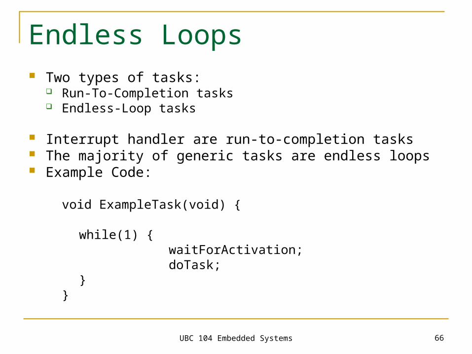
Endless Loops Two types of tasks:
Run-To-Completion tasks Endless-Loop tasks
Interrupt handler are run-to-completion tasks The majority of generic tasks are endless loops Example Code:
void ExampleTask(void) {
while(1) {waitForActivation;doTask;
}}
UBC 104 Embedded Systems 67
Idle Mode 8051s implement an “idle” mode
which consumes less power
UBC 104 Embedded Systems 68
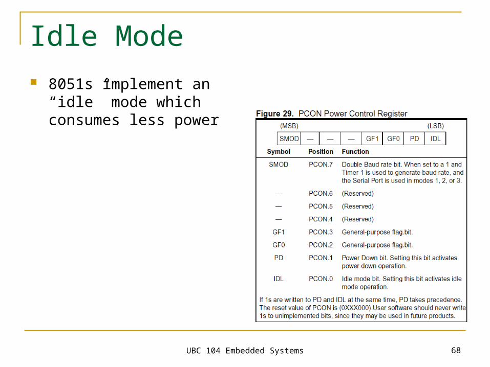
Idle Mode 8051s implement an “idle” mode
which consumes less power
UBC 104 Embedded Systems 69
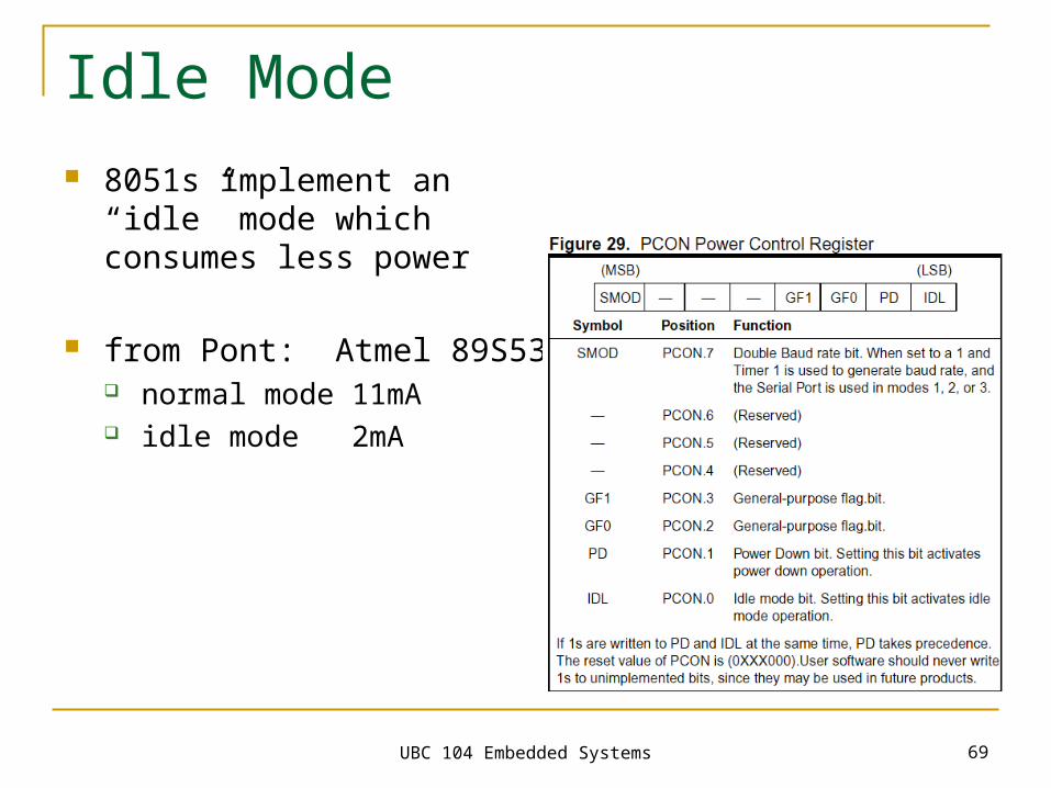
Idle Mode 8051s implement an “idle” mode
which consumes less power
from Pont: Atmel 89S53 normal mode 11mA idle mode 2mA
UBC 104 Embedded Systems 70
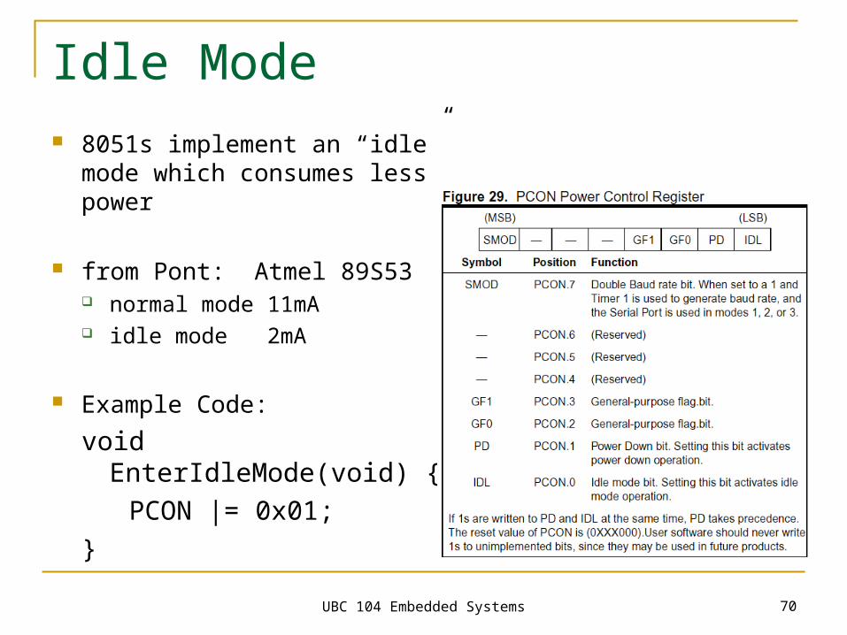
Idle Mode 8051s implement an “idle” mode
which consumes less power
from Pont: Atmel 89S53 normal mode 11mA idle mode 2mA
Example Code:
void EnterIdleMode(void) {
PCON |= 0x01;}
UBC 104 Embedded Systems 71
Generic main() Function
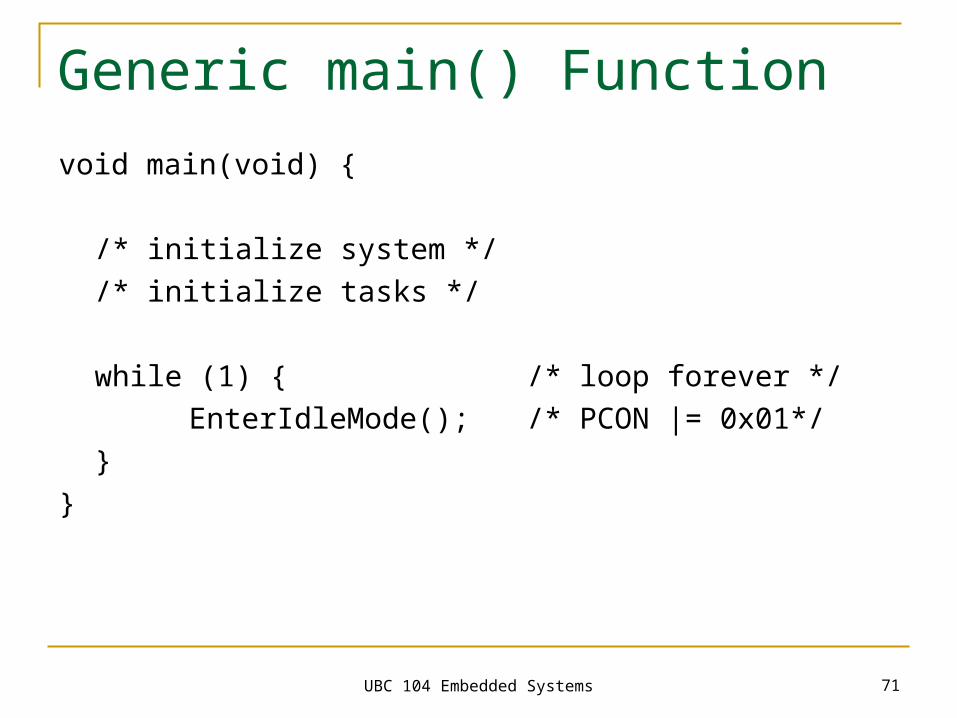
void main(void) {
/* initialize system *//* initialize tasks */
while (1) { /* loop forever */EnterIdleMode(); /* PCON |= 0x01*/
}}
UBC 104 Embedded Systems 72
Summary
Cyclic executives
Endless loops
Idle mode