Introduction to Karnaugh Maps - Computer Engineering Research Group
13
Introduction to Karnaugh Maps Review So far, you (the students) have been introduced to truth tables, and how to derive a Boolean circuit from them. We will do an example. Consider the truth table for a basic 2-input multiplexer. We can view the truth table as a sort of specification which says what a circuit should do. (Note: Ask whether they know what a multiplexer is.) S A B Y 0 0 0 0 0 0 1 0 0 1 0 1 0 1 1 1 1 0 0 0 1 0 1 1 1 1 0 0 1 1 1 1 We can write this as a standard sum of products (SSoP): Y = S’ @A @B’ + S’@A @B + S @A’@B + S @A @B = m 2 + m 3 + m 5 + m 7 = E(2, 3, 5, 7) We can reduce this circuit using Boolean algebra (specifically, the
Transcript of Introduction to Karnaugh Maps - Computer Engineering Research Group

Introduction to Karnaugh Maps
Review
So far, you (the students) have been introduced to truth tables, and how
to derive a Boolean circuit from them.
We will do an example.
Consider the truth table for a basic 2-input multiplexer. We can view the
truth table as a sort of specification which says what a circuit should do.
(Note: Ask whether they know what a multiplexer is.)
S A B Y
0 0 0 0
0 0 1 0
0 1 0 1
0 1 1 1
1 0 0 0
1 0 1 1
1 1 0 0
1 1 1 1
We can write this as a standard sum of products (SSoP):
Y = S’@A @B’ + S’@A @B + S @A’@B + S @A @B
= m2 + m3 + m5 + m7
= E(2, 3, 5, 7)
We can reduce this circuit using Boolean algebra (specifically, the
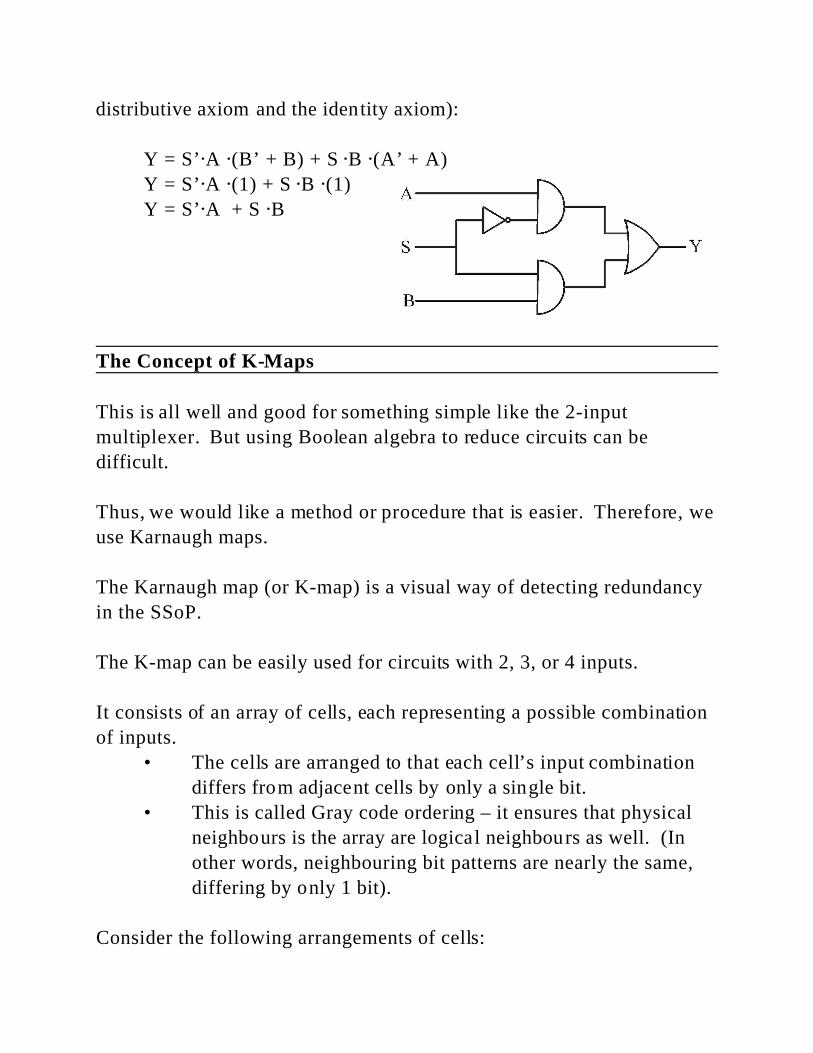
distributive axiom and the identity axiom):
Y = S’@A @(B’ + B) + S @B @(A’ + A)
Y = S’@A @(1) + S @B @(1)
Y = S’@A + S @B
The Concept of K-Maps
This is all well and good for something simple like the 2-input
multiplexer. But using Boolean algebra to reduce circuits can be
difficult.
Thus, we would like a method or procedure that is easier. Therefore, we
use Karnaugh maps.
The Karnaugh map (or K-map) is a visual way of detecting redundancy
in the SSoP.
The K-map can be easily used for circuits with 2, 3, or 4 inputs.
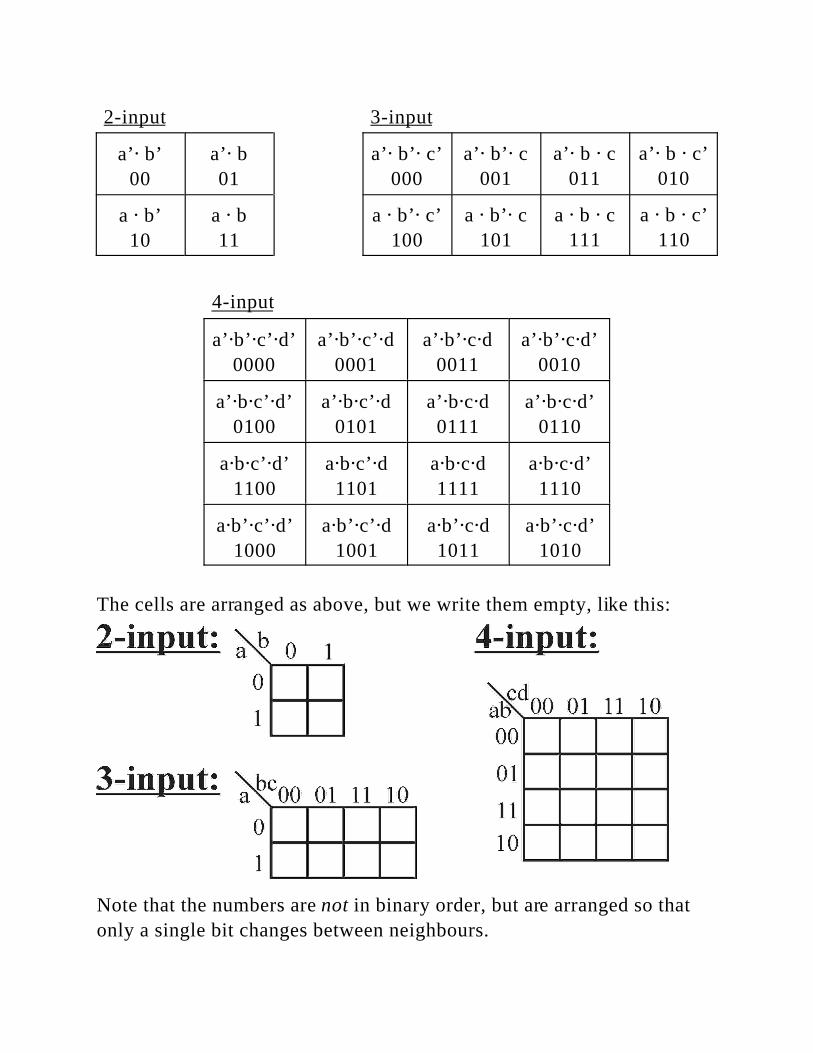
It consists of an array of cells, each representing a possible combination
of inputs.
• The cells are arranged to that each cell’s input combination
differs from adjacent cells by only a single bit.
• This is called Gray code ordering – it ensures that physical
neighbours is the array are logical neighbours as well. (In
other words, neighbouring bit patterns are nearly the same,
differing by only 1 bit).
Consider the following arrangements of cells:
2-input 3-input
a’@ b’
00
a’@ b
01
a’@ b’@ c’
000
a’@ b’@ c
001
a’@ b @ c
011
a’@ b @ c’
010
a @ b’
10
a @ b
11
a @ b’@ c’
100
a @ b’@ c
101
a @ b @ c
111
a @ b @ c’
110
4-input
a’@b’@c’@d’
0000
a’@b’@c’@d
0001
a’@b’@c@d
0011
a’@b’@c@d’
0010
a’@b@c’@d’
0100
a’@b@c’@d
0101
a’@b@c@d
0111
a’@b@c@d’
0110
a@b@c’@d’
1100
a@b@c’@d
1101
a@b@c@d
1111
a@b@c@d’
1110
a@b’@c’@d’
1000
a@b’@c’@d
1001
a@b’@c@d
1011
a@b’@c@d’
1010
The cells are arranged as above, but we write them empty, like this:
Note that the numbers are not in binary order, but are arranged so that
only a single bit changes between neighbours.
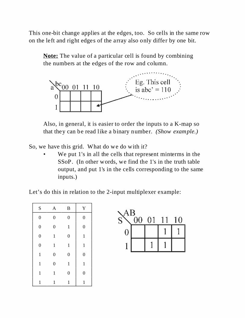
This one-bit change applies at the edges, too. So cells in the same row
on the left and right edges of the array also only differ by one bit.
Note: The value of a particular cell is found by combining
the numbers at the edges of the row and column.
Also, in general, it is easier to order the inputs to a K-map so
that they can be read like a binary number. (Show example.)
So, we have this grid. What do we do with it?
• We put 1's in all the cells that represent minterms in the
SSoP. (In other words, we find the 1's in the truth table
output, and put 1's in the cells corresponding to the same
inputs.)
Let’s do this in relation to the 2-input multiplexer example:
S A B Y
0 0 0 0
0 0 1 0
0 1 0 1
0 1 1 1
1 0 0 0
1 0 1 1
1 1 0 0
1 1 1 1
(1.)
(2.)
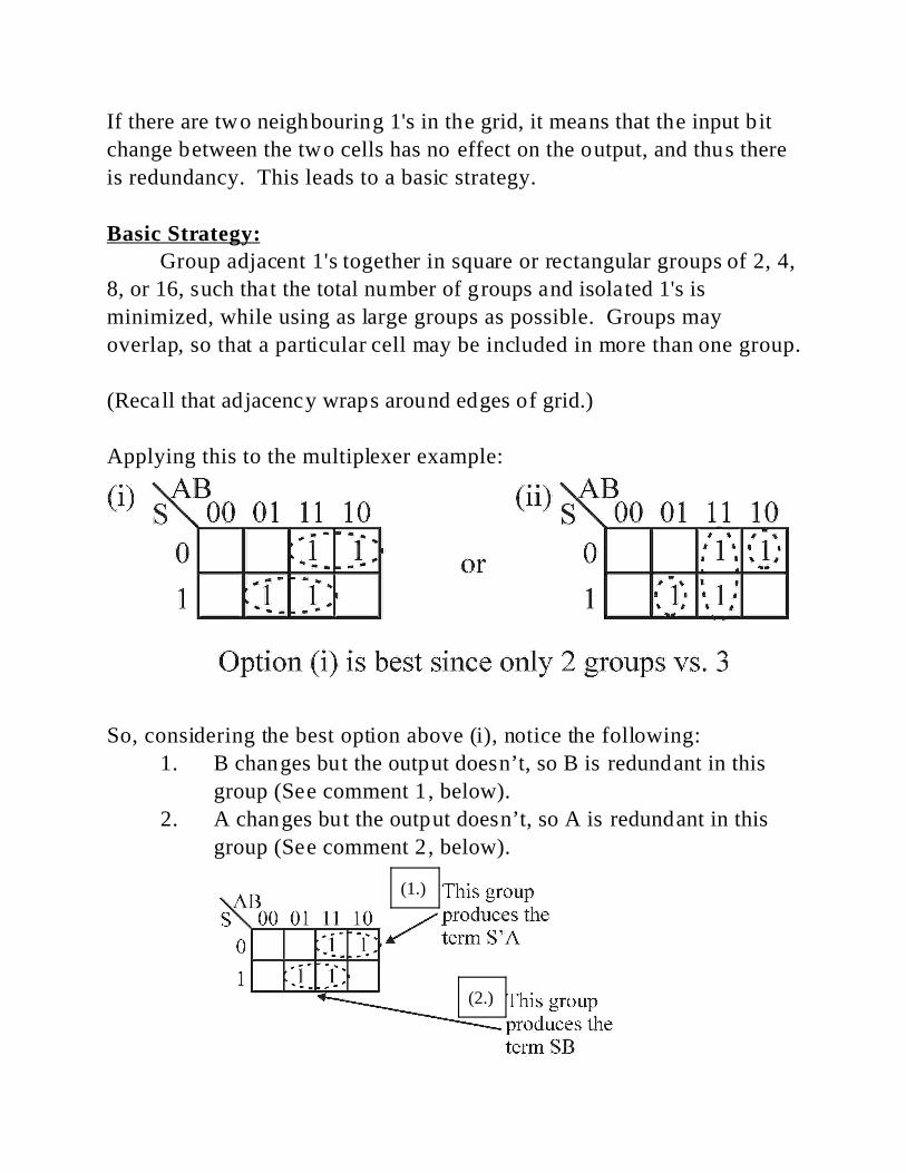
If there are two neighbouring 1's in the grid, it means that the input bit
change between the two cells has no effect on the output, and thus there
is redundancy. This leads to a basic strategy.
Basic Strategy:Group adjacent 1's together in square or rectangular groups of 2, 4,
8, or 16, such that the total number of groups and isolated 1's is
minimized, while using as large groups as possible. Groups may
overlap, so that a particular cell may be included in more than one group.
(Recall that adjacency wraps around edges of grid.)
Applying this to the multiplexer example:
So, considering the best option above (i), notice the following:
1. B changes but the output doesn’t, so B is redundant in this
group (See comment 1, below).
2. A changes but the output doesn’t, so A is redundant in this
group (See comment 2, below).
So, we write out Boolean expressions for each group, leaving out the
redundant elements. That is, for each group, we write out the inputs that
don’t change.
The multiplexer example, with two groups, gives us two terms,
Y = S@B + S’@A
which is the same as what we achieved through using Boolean algebra to
reduce the circuit.
So, we can summarize this process into a basic set of rules:
Rules for K-Maps1. Each cell with a 1 must be included in at least one group.
2. Try to form the largest possible groups.
3. Try to end up with as few groups as possible.
4. Groups may be in sizes that are powers of 2: 2 0 = 1, 21 = 2, 22
= 4, 23 = 8, 24 = 16, ...
5. Groups may be square or rectangular only (including wrap-
around at the grid edges). No diagonals or zig-zags can be
used to form a group.
6. The larger a group is, the more redundant inputs there are:
i. A group of 1 has no redundant inputs.
ii. A group of 2 has 1 redundant input.
iii. A group of 4 has 2 redundant inputs.
iv. A group of 8 has 3 redundant inputs.
v. A group of 16 has 4 redundant inputs.
The following simple examples illustrate rule 6 above.

Examples
2-input Example
A B Y
0 0 1
0 1 1
1 0 1
1 1 0
Direct from truth table: Y = A’B’ + A’B + AB’

3-input Example
A B C Y
0 0 0 0
0 0 1 0
0 1 0 1
0 1 1 1
1 0 0 1
1 0 1 0
1 1 0 1
1 1 1 1
Direct from truth table: Y = A’BC’ + A’BC + AB’C’ + ABC’ + ABC
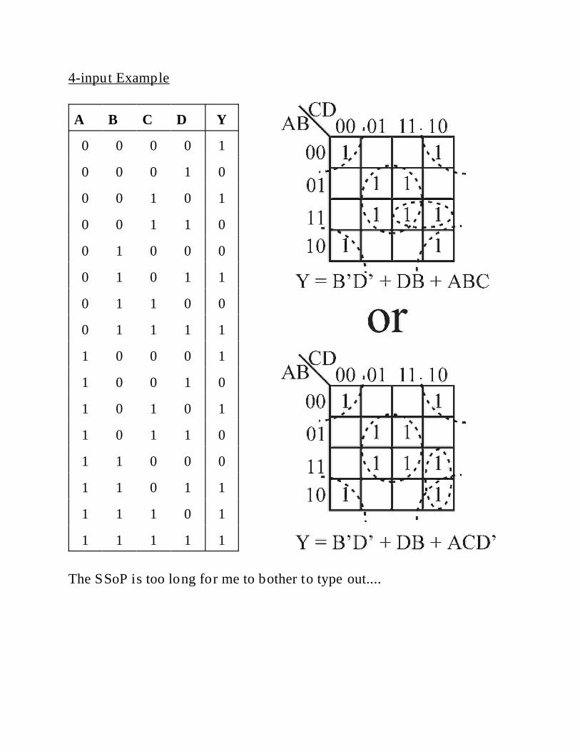
4-input Example
A B C D Y
0 0 0 0 1
0 0 0 1 0
0 0 1 0 1
0 0 1 1 0
0 1 0 0 0
0 1 0 1 1
0 1 1 0 0
0 1 1 1 1
1 0 0 0 1
1 0 0 1 0
1 0 1 0 1
1 0 1 1 0
1 1 0 0 0
1 1 0 1 1
1 1 1 0 1
1 1 1 1 1
The SSoP is too long for me to bother to type out....
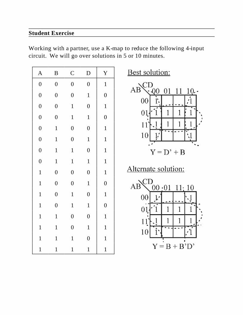
Student Exercise
Working with a partner, use a K-map to reduce the following 4-input
circuit. We will go over solutions in 5 or 10 minutes.
A B C D Y
0 0 0 0 1
0 0 0 1 0
0 0 1 0 1
0 0 1 1 0
0 1 0 0 1
0 1 0 1 1
0 1 1 0 1
0 1 1 1 1
1 0 0 0 1
1 0 0 1 0
1 0 1 0 1
1 0 1 1 0
1 1 0 0 1
1 1 0 1 1
1 1 1 0 1
1 1 1 1 1
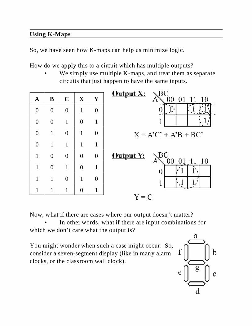
Using K-Maps
So, we have seen how K-maps can help us minimize logic.
How do we apply this to a circuit which has multiple outputs?
• We simply use multiple K-maps, and treat them as separate
circuits that just happen to have the same inputs.
A B C X Y
0 0 0 1 0
0 0 1 0 1
0 1 0 1 0
0 1 1 1 1
1 0 0 0 0
1 0 1 0 1
1 1 0 1 0
1 1 1 0 1
Now, what if there are cases where our output doesn’t matter?
• In other words, what if there are input combinations for
which we don’t care what the output is?
You might wonder when such a case might occur. So,
consider a seven-segment display (like in many alarm
clocks, or the classroom wall clock).
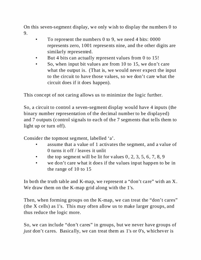
On this seven-segment display, we only wish to display the numbers 0 to
9.
• To represent the numbers 0 to 9, we need 4 bits: 0000
represents zero, 1001 represents nine, and the other digits are
similarly represented.
• But 4 bits can actually represent values from 0 to 15!
• So, when input bit values are from 10 to 15, we don’t care
what the output is. (That is, we would never expect the input
to the circuit to have those values, so we don’t care what the
circuit does if it does happen).
This concept of not caring allows us to minimize the logic further.
So, a circuit to control a seven-segment display would have 4 inputs (the
binary number representation of the decimal number to be displayed)
and 7 outputs (control signals to each of the 7 segments that tells them to
light up or turn off).
Consider the topmost segment, labelled ‘a’.
• assume that a value of 1 activates the segment, and a value of
0 turns it off / leaves it unlit
• the top segment will be lit for values 0 , 2, 3, 5, 6, 7, 8, 9
• we don’t care what it does if the values input happen to be in
the range of 10 to 15
In both the truth table and K-map, we represent a “don’t care” with an X.
We draw them on the K-map grid along with the 1's.
Then, when forming groups on the K-map, we can treat the “don’t cares”
(the X cells) as 1's. This may often allow us to make larger groups, and
thus reduce the logic more.
So, we can include “don’t cares” in groups, but we never have groups of
just don’t cares. Basically, we can treat them as 1's or 0's, whichever is
most convenient.
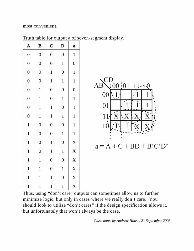
Truth table for output a of seven-segment display.
A B C D a
0 0 0 0 1
0 0 0 1 0
0 0 1 0 1
0 0 1 1 1
0 1 0 0 0
0 1 0 1 1
0 1 1 0 1
0 1 1 1 1
1 0 0 0 1
1 0 0 1 1
1 0 1 0 X
1 0 1 1 X
1 1 0 0 X
1 1 0 1 X
1 1 1 0 X
1 1 1 1 X
Thus, using “don’t care” outputs can sometimes allow us to further
minimize logic, but only in cases where we really don’t care. You
should look to utilize “don’t cares” if the design specification allows it,
but unfortunately that won’t always be the case.
Class notes by Andrew House, 21 September 2003.