Introduction to In-Vehicle Networking: Generic...
21
Management Information Systems ΤΕΧΝΟΛΟΓΙΕΣ ΤΗΛΕΠΙΚΟΙΝΩΝΙΩΝ ΚΑΙ ΔΙΚΤΥΩΝ Introduction to In-Vehicle Networking: Generic Protocols ΕΡΓΑΣΙΑ ΤΟΥ ΦΟΙΤΗΤΗ: ΜΑΣΤΡΑΚΟΥΛΗΣ ΓΙΩΡΓΟΣ ΑΜ:06/08 ΕΠΙΒΛΕΠΩΝ ΚΑΘΗΓΗΤΗΣ : ΑΝΑΣΤΑΣΙΟΣ Α. ΟΙΚΟΝΟΜΙΔΗΣ ΘΕΣΣΑΛΟΝΙΚΗ 2007
Transcript of Introduction to In-Vehicle Networking: Generic...
Management Information Systems
ΤΕΧΝΟΛΟΓΙΕΣ ΤΗΛΕΠΙΚΟΙΝΩΝΙΩΝ ΚΑΙ ΔΙΚΤΥΩΝ
Introduction to In-Vehicle Networking: Generic Protocols
ΕΡΓΑΣΙΑ ΤΟΥ ΦΟΙΤΗΤΗ: ΜΑΣΤΡΑΚΟΥΛΗΣ ΓΙΩΡΓΟΣ ΑΜ:06/08 ΕΠΙΒΛΕΠΩΝ ΚΑΘΗΓΗΤΗΣ : ΑΝΑΣΤΑΣΙΟΣ Α. ΟΙΚΟΝΟΜΙΔΗΣ
ΘΕΣΣΑΛΟΝΙΚΗ 2007
Contents
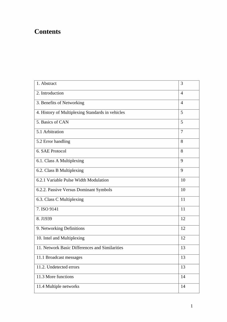
1. Abstract 3
2. Introduction 4
3. Benefits of Networking 4
4. History of Multiplexing Standards in vehicles 5
5. Basics of CAN 5
5.1 Arbitration 7
5.2 Error handling 8
6. SAE Protocol 8
6.1. Class A Multiplexing 9
6.2. Class B Multiplexing 9
6.2.1 Variable Pulse Width Modulation 10
6.2.2. Passive Versus Dominant Symbols 10
6.3. Class C Multiplexing 11
7. ISO 9141 11
8. J1939 12
9. Networking Definitions 12
10. Intel and Multiplexing 12
11. Network Basic Differences and Similarities 13
11.1 Broadcast messages 13
11.2. Undetected errors 13
11.3 More functions 14
11.4 Multiple networks 14
1
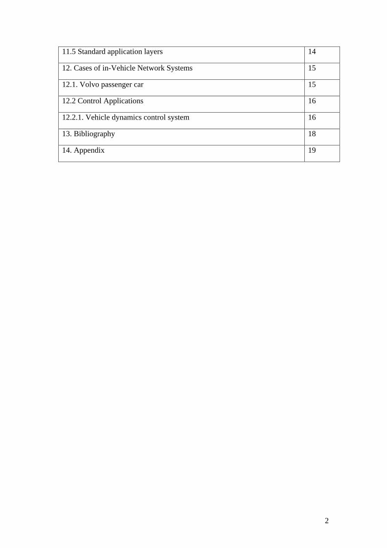
11.5 Standard application layers 14
12. Cases of in-Vehicle Network Systems 15
12.1. Volvo passenger car 15
12.2 Control Applications 16
12.2.1. Vehicle dynamics control system 16
13. Bibliography 18
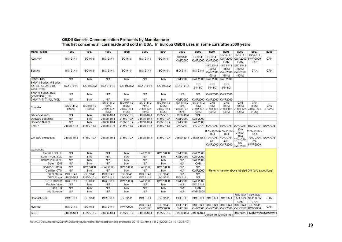
14. Appendix 19
2
1. Abstract In this paper we will have a brief analysis of the generic protocols that are used in the area of in-vehicle networking. In-vehicle networking, also known as multiplexing, is a method for transferring data among distributed electronic modules via a serial data bus. Thanks to this kind of technology modern cars have been equipped with all sorts of new features such as EDB, ABS, Anti-spin Control Systems and other Dynamic Control Systems that lead to safer vehicles. Also the idea of fuel saving combined with that of earth preservation is highly supported by the advantages of the use generic protocols in vehicles. After the benefits of networking, we will further proceed to the basics of generic protocols such as CAN, SAE, ISO 9141 and J1939. We will also refer not only to the role of automotive companies but also to that of the area of electronics such as Intel. The importance of the role of Intel in the in-Vehicle networking procedure is established by the extended use of the generic protocols such as CAN or J1850 in its new product series. A very knowledgeable section of this introduction is consumed on the presentation of the differences and the similarities between some of the generic protocols. Finally we will finish off this brief introduction to the In-Vehicle Networking by presenting some true cases of in-vehicle networking and the benefits that derive from its use, such as the Dynamic Control System manufactured by Bosch.
3
2. Introduction Today's vehicles contain hundreds of circuits, sensors, and many other electrical components. Communication is needed among the many circuits and functions of the vehicle. For example, when the driver presses the headlights switch on the dashboard, the headlights react. For this to occur, communication is needed between the dashboard switch and the front of the vehicle. In current vehicle systems this type of communication is handled via a dedicated wire through point-to-point connections. If all possible combinations of switches, sensors, motors, and other electrical devices in fully featured vehicles are accumulated, the resulting number of connections and dedicated wiring is enormous. Networking provides a more efficient method for today's complex in-vehicle communications.
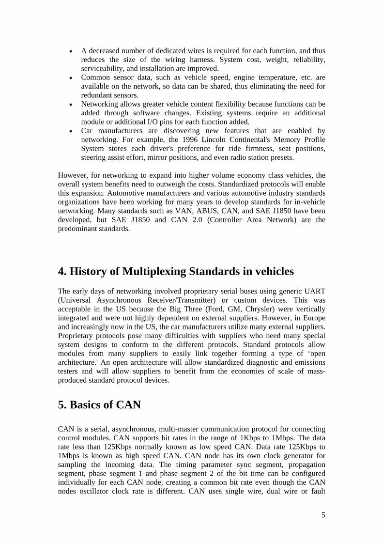
In-vehicle networking, also known as multiplexing, is a method for transferring data among distributed electronic modules via a serial data bus. Without serial networking, inter-module communication requires dedicated, point-to-point wiring resulting in bulky, expensive, complex, and difficult to install wiring harnesses. Applying a serial data bus reduces the number of wires by combining the signals on a single wire through time division multiplexing. Information is sent to individual control modules that control each function, such as anti-lock braking, turn signals, and dashboard displays (see figure 1).
As the electrical content of today's vehicles continues to increase the need for networking is even more evident. For example, some high-end luxury cars contain more than three miles and nearly 200 pounds of wiring. The resulting number of connectors creates a reliability nightmare.
3. Benefits of Networking In-vehicle networking provides many system-level benefits, many of which are only beginning to be realized.
4
• A decreased number of dedicated wires is required for each function, and thus reduces the size of the wiring harness. System cost, weight, reliability, serviceability, and installation are improved.
• Common sensor data, such as vehicle speed, engine temperature, etc. are available on the network, so data can be shared, thus eliminating the need for redundant sensors.
• Networking allows greater vehicle content flexibility because functions can be added through software changes. Existing systems require an additional module or additional I/O pins for each function added.
• Car manufacturers are discovering new features that are enabled by networking. For example, the 1996 Lincoln Continental's Memory Profile System stores each driver's preference for ride firmness, seat positions, steering assist effort, mirror positions, and even radio station presets.
However, for networking to expand into higher volume economy class vehicles, the overall system benefits need to outweigh the costs. Standardized protocols will enable this expansion. Automotive manufacturers and various automotive industry standards organizations have been working for many years to develop standards for in-vehicle networking. Many standards such as VAN, ABUS, CAN, and SAE J1850 have been developed, but SAE J1850 and CAN 2.0 (Controller Area Network) are the predominant standards.
4. History of Multiplexing Standards in vehicles The early days of networking involved proprietary serial buses using generic UART (Universal Asynchronous Receiver/Transmitter) or custom devices. This was acceptable in the US because the Big Three (Ford, GM, Chrysler) were vertically integrated and were not highly dependent on external suppliers. However, in Europe and increasingly now in the US, the car manufacturers utilize many external suppliers. Proprietary protocols pose many difficulties with suppliers who need many special system designs to conform to the different protocols. Standard protocols allow modules from many suppliers to easily link together forming a type of ‘open architecture.' An open architecture will allow standardized diagnostic and emissions testers and will allow suppliers to benefit from the economies of scale of mass-produced standard protocol devices. 5. Basics of CAN CAN is a serial, asynchronous, multi-master communication protocol for connecting control modules. CAN supports bit rates in the range of 1Kbps to 1Mbps. The data rate less than 125Kbps normally known as low speed CAN. Data rate 125Kbps to 1Mbps is known as high speed CAN. CAN node has its own clock generator for sampling the incoming data. The timing parameter sync segment, propagation segment, phase segment 1 and phase segment 2 of the bit time can be configured individually for each CAN node, creating a common bit rate even though the CAN nodes oscillator clock rate is different. CAN uses single wire, dual wire or fault
5
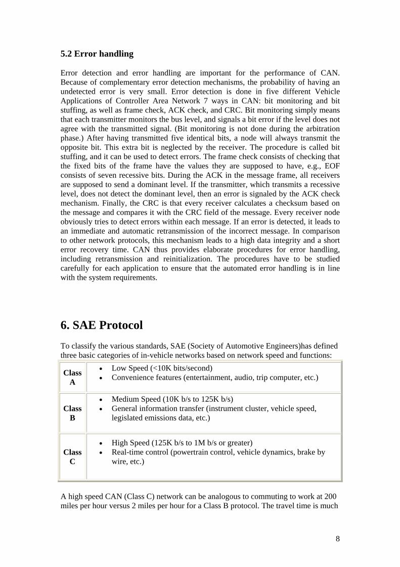
tolerant techniques for signaling. In single wire CAN data rates are 33.3Kbps and 83.33Kbps and signaling is single ended. Dual wire CAN data rates are at high speed CAN and signaling is differential. Fault tolerant CAN intended for low speed CAN. If any wire is shorted to battery or ground, fault tolerant CAN still be operational. At this point we have to add that binary zero is represented by a "dominant" state in the bus and binary one by a recessive state, so a binary zero takes precedence over a one, so lower numbered message identifiers have priority over higher numbered ones. CAN is a CSMA/CD protocol. If the network is idle, any node can send a message. If two messages are sent simultaneously, the node that sends a recessive bit, but detects a dominant bit stops transmitting, leaving the network free for the higher priority message. The higher priority message is not corrupted. In the automotive industry, embedded control has grown from stand-alone systems to highly integrated and networked control systems. By networking electro-mechanical subsystems, it becomes possible to modularize functionalities and hardware, which facilitates reuse and adds capabilities. Fig 3. shows an example of an electronic control unit (ECU) mounted on a diesel engine of a Scania truck. The ECU handles the control of engine, turbo, fan, etc. but also the CAN communication. Combining networks and mechatronic modules makes it possible to reduce both the cabling and the number of connectors, which facilitates production and increases reliability. Introducing networks in vehicles also makes it possible to more efficiently carry out diagnostics and to coordinate the operation of the separate subsystems. The CAN protocol standardizes the physical and data link layers, which are the two lowest layers of the open systems interconnect (OSI) communication model (see Fig. 2). For most systems, higher-layer protocols are needed to enable efficient development and operation. Such protocols are needed for defining how the CAN protocol should be used in applications, for example, how to refer to the configuration of identifiers with respect to application messages, how to package application messages into frames, and how to deal with start-up and fault handling. Note that in many cases only a few of the OSI layers are required. Note also that real-time issues and redundancy management are not covered by the OSI model. The adoption of CAN in a variety of application fields has led to the development of several higher-layer protocols, including SAE J1939, CANopen, DeviceNet, and CAN Kingdom. Their characteristics reflect differences in requirements and traditions of application areas. An example is the adoption of certain communication models, such as either the client-server model or the distributed data-flow model. The progress and success of CAN are due to a number of factors. The evolution of microelectronics paved the way for introducing distributed control in vehicles. In the early 1980s there was, however, a lack of low-cost and standardized protocols suitable for real-time control systems. Therefore, in 1983 Kiencke started the development of a new serial bus system at Bosch, which was presented as CAN in 1986 at the SAE congress in Detroit. The CAN protocol was internationally standardized in 1993 as ISO 11898-1. The development of CAN was mainly motivated by the need for new functionality, but it also reduced the need for wiring. The use of CAN in the automotive industry has caused mass production of CAN controllers. Today, CAN controllers are integrated on many microcontrollers and available at a low cost.
6
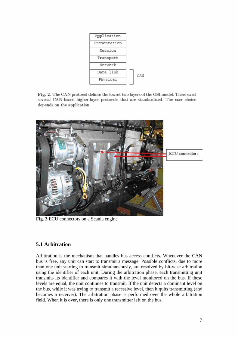
Fig. 3 ECU connectors on a Scania engine
5.1 Arbitration
Arbitration is the mechanism that handles bus access conflicts. Whenever the CAN bus is free, any unit can start to transmit a message. Possible conflicts, due to more than one unit starting to transmit simultaneously, are resolved by bit-wise arbitration using the identifier of each unit. During the arbitration phase, each transmitting unit transmits its identifier and compares it with the level monitored on the bus. If these levels are equal, the unit continues to transmit. If the unit detects a dominant level on the bus, while it was trying to transmit a recessive level, then it quits transmitting (and becomes a receiver). The arbitration phase is performed over the whole arbitration field. When it is over, there is only one transmitter left on the bus.
7
5.2 Error handling
Error detection and error handling are important for the performance of CAN. Because of complementary error detection mechanisms, the probability of having an undetected error is very small. Error detection is done in five different Vehicle Applications of Controller Area Network 7 ways in CAN: bit monitoring and bit stuffing, as well as frame check, ACK check, and CRC. Bit monitoring simply means that each transmitter monitors the bus level, and signals a bit error if the level does not agree with the transmitted signal. (Bit monitoring is not done during the arbitration phase.) After having transmitted five identical bits, a node will always transmit the opposite bit. This extra bit is neglected by the receiver. The procedure is called bit stuffing, and it can be used to detect errors. The frame check consists of checking that the fixed bits of the frame have the values they are supposed to have, e.g., EOF consists of seven recessive bits. During the ACK in the message frame, all receivers are supposed to send a dominant level. If the transmitter, which transmits a recessive level, does not detect the dominant level, then an error is signaled by the ACK check mechanism. Finally, the CRC is that every receiver calculates a checksum based on the message and compares it with the CRC field of the message. Every receiver node obviously tries to detect errors within each message. If an error is detected, it leads to an immediate and automatic retransmission of the incorrect message. In comparison to other network protocols, this mechanism leads to a high data integrity and a short error recovery time. CAN thus provides elaborate procedures for error handling, including retransmission and reinitialization. The procedures have to be studied carefully for each application to ensure that the automated error handling is in line with the system requirements.
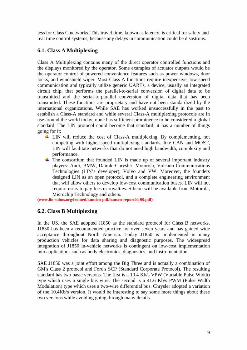
6. SAE Protocol To classify the various standards, SAE (Society of Automotive Engineers)has defined three basic categories of in-vehicle networks based on network speed and functions:
Class A
• Low Speed (<10K bits/second) • Convenience features (entertainment, audio, trip computer, etc.)
Class B
• Medium Speed (10K b/s to 125K b/s) • General information transfer (instrument cluster, vehicle speed,
legislated emissions data, etc.)
Class C
• High Speed (125K b/s to 1M b/s or greater) • Real-time control (powertrain control, vehicle dynamics, brake by
wire, etc.)
A high speed CAN (Class C) network can be analogous to commuting to work at 200 miles per hour versus 2 miles per hour for a Class B protocol. The travel time is much
8
less for Class C networks. This travel time, known as latency, is critical for safety and real time control systems, because any delays in communication could be disastrous.
6.1. Class A Multiplexing
Class A Multiplexing contains many of the direct operator controlled functions and the displays monitored by the operator. Some examples of actuator outputs would be the operator control of powered convenience features such as power windows, door locks, and windshield wiper. Most Class A functions require inexpensive, low-speed communication and typically utilize generic UARTs, a device, usually an integrated circuit chip, that performs the parallel-to-serial conversion of digital data to be transmitted and the serial-to-parallel conversion of digital data that has been transmitted. These functions are proprietary and have not been standardized by the international organizations. While SAE has worked unsuccessfully in the past to establish a Class-A standard and while several Class-A multiplexing protocols are in use around the world today, none has sufficient prominence to be considered a global standard. The LIN protocol could become that standard; it has a number of things going for it:
LIN will reduce the cost of Class-A multiplexing. By complementing, not competing with higher-speed multiplexing standards, like CAN and MOST, LIN will facilitate networks that do not need high bandwidth, complexity and performance.
The consortium that founded LIN is made up of several important industry players: Audi, BMW, DaimlerChrysler, Motorola, Volcano Communications Technologies (LIN’s developer), Volvo and VW. Moreover, the founders designed LIN as an open protocol, and a complete engineering environment that will allow others to develop low-cost communication buses. LIN will not require users to pay fees or royalties. Silicon will be available from Motorola, Microchip Technology and others.
(www.lin-subus.org/fronted/kunden-pdf/hansen-report04-00.pdf)
6.2. Class B Multiplexing
In the US, the SAE adopted J1850 as the standard protocol for Class B networks. J1850 has been a recommended practice for over seven years and has gained wide acceptance throughout North America. Today J1850 is implemented in many production vehicles for data sharing and diagnostic purposes. The widespread integration of J1850 in-vehicle networks is contingent on low-cost implementation into applications such as body electronics, diagnostics, and instrumentation.
SAE J1850 was a joint effort among the Big Three and is actually a combination of GM's Class 2 protocol and Ford's SCP (Standard Corporate Protocol). The resulting standard has two basic versions. The first is a 10.4 Kb/s VPW (Variable Pulse Width) type which uses a single bus wire. The second is a 41.6 Kb/s PWM (Pulse Width Modulation) type which uses a two-wire differential bus. Chrysler adopted a variation of the 10.4Kb/s version. It would be interesting to say some more things about these two versions while avoiding going through many details.
9
6.2.1 Variable Pulse Width Modulation
VPW is the encoding scheme of choice for all 10.4Kb/s J1850 implementations. Automotive environments place hard demands for low radiated emissions. VPW offers one of the lowest radiated emissions encoding schemes possible due to the minimization of bus transitions per data bit. Some of the key attributes of VPW are its ability to compensate for clock mismatch and ground offsets, fixed transition and sample points, the low number of transitions per bit, and the fact that it is well suited for arbitration. However, VPW does not offer fixed data rates and initially can be a bit confusing. VPW communicates via time dependent symbols. For example, a “one” bit is not necessarily a high potential on the bus. With VPW, a “one” bit is a symbol denoted by a transition on the bus that lasts for some fixed amount of time, say 64ms. The bus can transition from a low potential to a high potential, or visa-versa; but it is the amount of time that the bus stays in its high or low potential that determines what a particular bus symbol is. In this case, if the bus remains in its high potential for 64ms, then we would consider the symbol to be a “one” bit. VPW J1850 protocol defines a high potential bus driven for 64ms as a “dominant one” bit. The reason it is dominant is due to the J1850 bus drive circuitry.
6.2.2. Passive Versus Dominant Symbols
The VPW J1850 bus is weakly pulled low, and driven high by a strong pull-up transistor at each node. This means that when no activity is present on the J1850 bus, it is weakly drawn to ground. Whenever a node wants to talk on the J1850 bus, it can either let the weakly drawn bus settle to its low potential at ground, or it can drive the bus to a high potential of approximately 7.5 Volts with its strong pull-up transistor. According to the J1850 VPW standard, a high potential can be anything from 4.25 Volts to 20 Volts. A low potential can be anything from a noisy ground to 3.5 Volts. With this given hardware configuration, any node driving the J1850 bus to a high potential will over-drive any other node wishing to allow the J1850 bus to settle down to a low potential or ground. For this reason, any symbols present on the J1850 bus utilizing a low potential state are considered passive. And conversely, any symbols present on the J1850 bus in the high potential state are considered dominant. (ftp://download.intel.com/design/intarch/papers/j1850_wp.pdf)
A strong force driving the standardization of J1850 was emissions legislation. CARB (California Air Resources Board) established OBD-II (On Board Diagnostics II) which requires the implementation of diagnostic tools for emission-related systems. OBD-II specifies that stored fault codes be available through a diagnostic port via a standard protocol. Currently, OBD-II specifies J1850 and the European standard, ISO 9141-2.
10
6.3. Class C Multiplexing
The predominant Class C protocol is CAN 2.0. The CAN protocol is targeted at high-speed, real-time control and can operate at up to 1 Mb/s. Robert Bosch GmbH developed the CAN protocol in the early 1980s and worked with Intel on the first silicon implementation, namely, the 82526 controller. This initial implementation of CAN version 1.2 (now known as version 2.0 part A) only allows for an 11-bit message identifier, thus limiting the number of distinct messages to 2032. In 1993 Intel released a new controller, the 82527, the first component to support the latest version of CAN version 2.0B. CAN 2.0B supports both the standard 11-bit and enhanced 29-bit identifier, allowing millions of distinct messages.
ISO in Europe has adopted CAN as the high-speed networking protocol. European automakers have expressed immediate need for the CAN protocol, particularly for luxury models, due to the advantages in-vehicle networking offers to the highly distributed nature of their electronic subsystems. The CAN protocol was first implemented in a 1991 S-class Mercedes Benz, and has since been adopted by BMW, Volvo, VW, Renault, PSA, and others.
In the US, CAN acceptance is growing. The SAE Truck and Bus Control and Communications subcommittee selected CAN in 1994 as the basis for J1939, the class C network for truck and bus applications. For class C automotive networks, the SAE formed a task force to develop a recommended practice for US passenger cars utilizing the CAN protocol. Members from the Big Three, module suppliers, and silicon vendors are participating.
7. ISO 9141 This is an alternative standard to J1850 for protocols that must interface with a diagnostic port. While Ford's “domestic” products use J1850 (SCP), their international ones use ISO 9141. There is a protocol referred to as “Ford 9141” which appears to be distinct from Ford's UBP and based on ISO 9141. The NSI web-site has an introduction (in French) to ISO-9141. According to this site, it specifies "the characteristics of numerical exchange of information between the electronic control units embarked aboard road vehicles and suitable equipment of diagnosis." There are alternative configurations of the physical layer, one or two wire. It also specifies speed (5 baud for addresses and between 10 baud and 10 k baud for other transmissions), time intervals between key words and data transmission, message format and so on. Whether communication is point to point or multipoint is specified by individual manufacturers, so network access appears not to be specified in this standard.
11
8. J1939 J1939 is a high speed (Class C) network to support real time closed loop control functions between ECUs within a vehicle. Its documentation covers all layers in the ISO/OSI stack, so its scope is broader than, say CAN. J1931 does not necessarily formally define all layers. It uses CAN so network access and message format are consistent with it. The CAN 2.0B format is used with 29 bit message identifiers. The format of these 29 bits is defined in the standard and explained in the Kvaser tutorial, available from the Kvaser web-site. The speed of J1939 is 250 Kb/s, so it is slower than J2284. The physical medium is intended to be shielded twisted pair. The standard can be purchased from the SAE. Network Protocols used in Automotive Industry - www.aber.ac.uk/compsci/Research/mbsg/fmeaprojects/SoftFMEAtechreports/systems/protocols.pdf
9. Networking Definitions Both SAE J1850 and CAN 2.0 are CSMA/CR (Carrier Sense, Multiple Access with Collision Resolution) arbitration protocols. Through a multi-master architecture, prioritized messages are sent on a serial bus. When two or more nodes try to transmit a message at the same time, the protocols handle message contention by arbitration. The lowest priority nodes lose, but the highest priority message successfully reaches its destination without being destroyed by the collision, hence `collision resolution.'
10. Intel and Multiplexing Intel has been a key player in standardized automotive in-vehicle networking since the early days of CAN in the mid 80s. With the development of the 82526 and the standalone and integrated versions of the 82527 CAN architecture, Intel has taken the lead in CAN products development. Now, Intel is integrating J1850 functionality into the MCS® 96 product line.
The Intel standalone 82527 and integrated CAN 2.0B communications controllers are based on the same full CAN architecture. These controllers handle all communication functions, including message transmission, reception, error detection and error confinement. This minimizes the burden of the host microcontroller to manage communications, allowing the controller to handle its application functions, such as engine control or anti-lock braking. Intel has integrated this CAN architecture on two members of the MCS 96 microcontroller family, the 87C196CA and 87C196CB.
Intel also supports the SAE J1850 protocol with an integrated protocol handler on the 87C196LB, a 16-bit microcontroller. This J1850 protocol handler supports network functions including access, arbitration, in-frame response, error detection, and delay compensation. A digital noise filter automatically rejects unwanted noise pulses. To minimize CPU overhead, three dedicated interrupts and byte-level message buffering provide for efficient message handling. The protocol handler has dedicated hardware to support low-level network functions, yet is flexible enough to support GM and Chrysler J1850 specifications.
12
11. Network Basic Differences and Similarities
11.1 Broadcast messages
The most noticeable common feature of these protocols seems to be that messages are broadcast so all receivers receive the message and can act upon it if they are interested. This is necessary as some sensors will transmit data of interest to several systems, such as road wheel sensor data being of interest to ABS, traction control, instrumentation (speedometer) and possibly others. The only exception seems to be that some implementations of ISO 9141 use point to point communication. This does not seem an important exception from the point of view of the project (as these older standards appear to be being phased out) but if we ever wanted to model telecommunications systems we might need to model point to point communication. Broadcast messages immediately introduce a problem in using SDL to model network message passing, as an SDL "signal" is sent to a specific recipient, though it may be broadcast in the sense of being sent by all available paths, in much the way that an Ethernet message is sent to every node on the network, but is addressed to a specific receiver. In CAN, for example, the transmitter will not know which nodes are interested in the message, it broadcasts it to all and sundry, similarly to a radio broadcast, the message being identified by its source, not its recipient. An SDL signal can have its sender identified. Of course, in the context of a subsystem, we might be able to dodge this issue, by simply modelling the message being sent from the subsystem's (only) sender to its (only) receiver, but this fails to model the protocol, and also fails to address situations where the system has several receivers of the same message, such as separate ECUs for each lamp cluster.
11.2. Undetected errors
According to Comparison CAN vs. Byteight vs. TTP/C, CAN, Byteight and TTP/C all use a CRC and all have a hamming distance of 6, so the probability of an undetected error is more or less equal in each case. I imagine that the same applies to Volcano, being based on CAN. The probability is not equal as it will be affected by the length of the message, there being a greater probability of six bits being corrupted in a long message than a short one. This makes the probability of an undetected error vanishingly small, but of course if a fault in a sensor, say, causes it to send an incorrect reading, this will be transmitted accurately and so will lead to incorrect behaviour. This is, of course, not a fault with the network. Some older protocols (such as UBP) use a checksum rather than a CRC, which makes an undetected error less unlikely. The probability is still low and, in view of these protocols' obsolescence the difference can probably be ignored. Of course a detected error will lead to the message being retransmitted which will result in a delay in its correct reception, especially if it needs to contend for network access again (as in CAN). Late messages clearly need modelling. CAN's error containment might result in a node being rendered inactive (so-called “bus off” mode). This might result in a fault mitigation strategy being invoked by the receiver. This feature should be modelled, but arguably need not be distinguished from messages being lost for any other reason (the message not transmitted or message not received faults listed in Generic Network FMEA.
13
11.3 More functions
One of the key benefits of networking is the ability to add functions without adding new hardware or decreasing reliability. As the networking capability becomes common on mid- and low-priced automobiles, the car manufacturers will be able to easily offer functionality found today only on high-end vehicles. Traditionally proprietary Class A functions will move to the standard networks like J1850 and CAN to benefit from the available shared data and standardization.
11.4 Multiple networks
Not all networks are created equal. The need for speed and low latency are critical for powertrain control and vehicle dynamics. However, the driver compartment functions like power windows and instrumentation only require a speed sufficient to exceed human perception. To optimize the costs and control data access, multiple networks in a single vehicle are becoming common. For example, a CAN network running at 500 Kb/s may link the engine, transmission, and ABS, while a slower CAN network or J1850 network would link the doors, instrumentation, and other body electronics. A gateway would transfer required diagnostic information between the multiple networks.
11.5 Standard application layers
Not only is there a benefit to a standardized protocol at the data link and physical layers, but also system designers are seeing the benefits of standardized application layer protocols. While this is more common in industrial control standards for CAN, but it is also appearing in automotive applications. Examples include: SAE J1939, OSEK from the German automotive consortium, SDS from Honeywell, and DeviceNet from Allen-Bradley. These standards allow system designers to avoid low-level protocol details and focus on the application itself. However, the impact of this type of standardization is increased demand on the microcontrollers and protocol devices, and thus the need for efficient message handling and standardized protocol devices will become even more important (www.intel.com/design/mcs96/papers/autolxbk.htm)
14
12. Cases of in-Vehicle Network Systems
12.1. Volvo passenger car
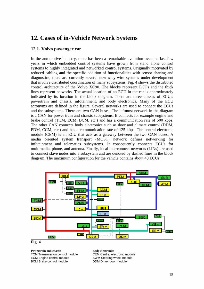
In the automotive industry, there has been a remarkable evolution over the last few years in which embedded control systems have grown from stand alone control systems to highly integrated and networked control systems. Originally motivated by reduced cabling and the specific addition of functionalities with sensor sharing and diagnostics, there are currently several new x-by-wire systems under development that involve distributed coordination of many subsystems. Fig. 4 shows the distributed control architecture of the Volvo XC90. The blocks represent ECUs and the thick lines represent networks. The actual location of an ECU in the car is approximately indicated by its location in the block diagram. There are three classes of ECUs: powertrain and chassis, infotainment, and body electronics. Many of the ECU acronyms are defined in the figure. Several networks are used to connect the ECUs and the subsystems. There are two CAN buses. The leftmost network in the diagram is a CAN for power train and chassis subsystems. It connects for example engine and brake control (TCM, ECM, BCM, etc.) and has a communication rate of 500 kbps. The other CAN connects body electronics such as door and climate control (DDM, PDM, CCM, etc.) and has a communication rate of 125 kbps. The central electronic module (CEM) is an ECU that acts as a gateway between the two CAN buses. A media oriented system transport (MOST) network defines networking for infotainment and telematics subsystems. It consequently connects ECUs for multimedia, phone, and antenna. Finally, local interconnect networks (LINs) are used to connect slave nodes into a subsystem and are denoted by dashed lines in the block diagram. The maximum configuration for the vehicle contains about 40 ECUs .
Fig. 4 Powertrain and chassis Body electronics TCM Transmission control module CEM Central electronic module ECM Engine control module SWM Steering wheel module BCM Brake control module DDM Driver door module
15
BSC Body sensor cluster REM Rear electronic module SAS Steering angle sensor SWM Steering wheel module SUM Suspension module DDM Driver door module AUD Audio module PDM Passenger door module REM Rear electronic module Infotainment/Telematics CCM Climate control module MP1,2 Media players 1 and 2 ICM Infotainment control PHM Phone module UEM Upper electronic module MMM Multimedia module DIM Driver information module SUB Subwoofer AEM Auxiliary electronic ATM Antenna tuner module
12.2 Control Applications
A vehicular control systems with loops closed over CAN buses will be discussed in this section. The specific example is a vehicle dynamics control system for passenger cars that is manufactured by Bosch.
12.2.1. Vehicle dynamics control system
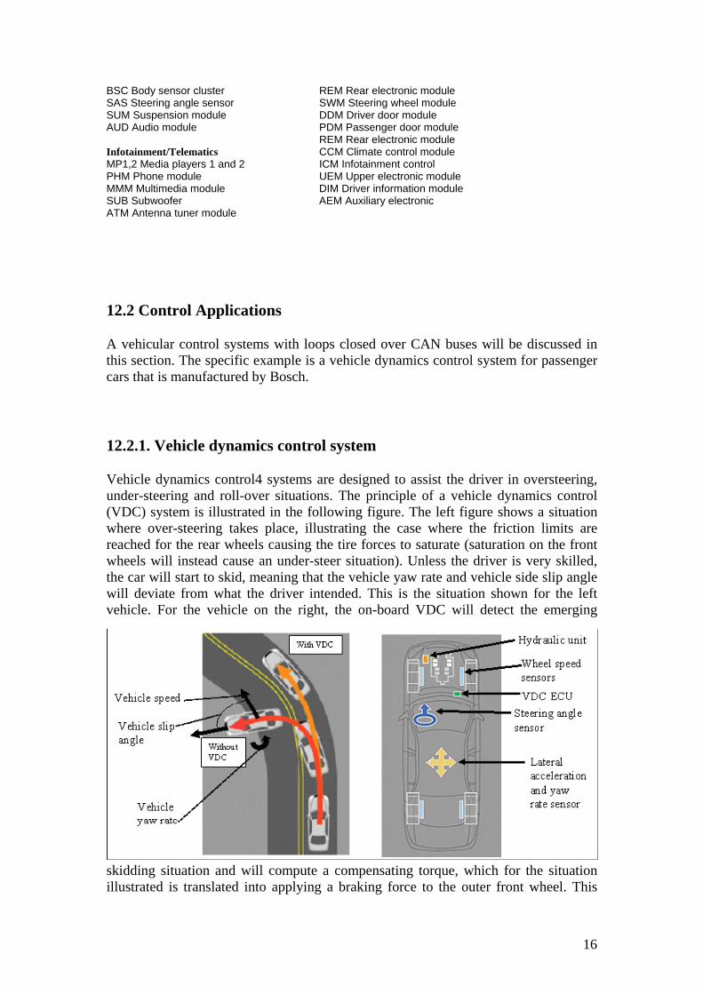
Vehicle dynamics control4 systems are designed to assist the driver in oversteering, under-steering and roll-over situations. The principle of a vehicle dynamics control (VDC) system is illustrated in the following figure. The left figure shows a situation where over-steering takes place, illustrating the case where the friction limits are reached for the rear wheels causing the tire forces to saturate (saturation on the front wheels will instead cause an under-steer situation). Unless the driver is very skilled, the car will start to skid, meaning that the vehicle yaw rate and vehicle side slip angle will deviate from what the driver intended. This is the situation shown for the left vehicle. For the vehicle on the right, the on-board VDC will detect the emerging
skidding situation and will compute a compensating torque, which for the situation illustrated is translated into applying a braking force to the outer front wheel. This
16
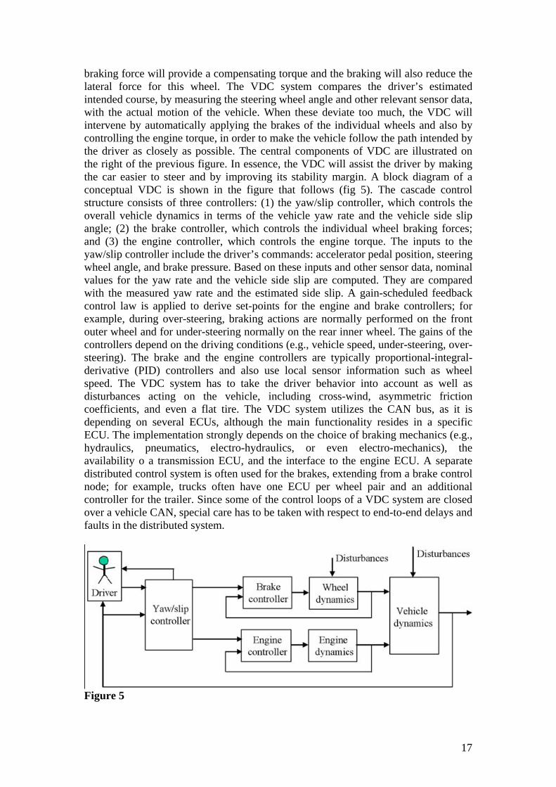
braking force will provide a compensating torque and the braking will also reduce the lateral force for this wheel. The VDC system compares the driver’s estimated intended course, by measuring the steering wheel angle and other relevant sensor data, with the actual motion of the vehicle. When these deviate too much, the VDC will intervene by automatically applying the brakes of the individual wheels and also by controlling the engine torque, in order to make the vehicle follow the path intended by the driver as closely as possible. The central components of VDC are illustrated on the right of the previous figure. In essence, the VDC will assist the driver by making the car easier to steer and by improving its stability margin. A block diagram of a conceptual VDC is shown in the figure that follows (fig 5). The cascade control structure consists of three controllers: (1) the yaw/slip controller, which controls the overall vehicle dynamics in terms of the vehicle yaw rate and the vehicle side slip angle; (2) the brake controller, which controls the individual wheel braking forces; and (3) the engine controller, which controls the engine torque. The inputs to the yaw/slip controller include the driver’s commands: accelerator pedal position, steering wheel angle, and brake pressure. Based on these inputs and other sensor data, nominal values for the yaw rate and the vehicle side slip are computed. They are compared with the measured yaw rate and the estimated side slip. A gain-scheduled feedback control law is applied to derive set-points for the engine and brake controllers; for example, during over-steering, braking actions are normally performed on the front outer wheel and for under-steering normally on the rear inner wheel. The gains of the controllers depend on the driving conditions (e.g., vehicle speed, under-steering, over-steering). The brake and the engine controllers are typically proportional-integral-derivative (PID) controllers and also use local sensor information such as wheel speed. The VDC system has to take the driver behavior into account as well as disturbances acting on the vehicle, including cross-wind, asymmetric friction coefficients, and even a flat tire. The VDC system utilizes the CAN bus, as it is depending on several ECUs, although the main functionality resides in a specific ECU. The implementation strongly depends on the choice of braking mechanics (e.g., hydraulics, pneumatics, electro-hydraulics, or even electro-mechanics), the availability o a transmission ECU, and the interface to the engine ECU. A separate distributed control system is often used for the brakes, extending from a brake control node; for example, trucks often have one ECU per wheel pair and an additional controller for the trailer. Since some of the control loops of a VDC system are closed over a vehicle CAN, special care has to be taken with respect to end-to-end delays and faults in the distributed system.
Figure 5
17
18
13. Bibliography Simplify CAN and LIN In-vehicle Network Testing – Tektronix -
http://www.techonline.com/learning/techpaper/193103328 Introduction To In Vehicle Networking -
(www.intel.com/design/mcs96/papers/autolxbk.htm) www.lin-subus.org/fronted/kunden-pdf/hansen-report04-00.pdf Implementing the J1850 Protocol -
www.intel.com/design/intarch/papers/j1850_wp.htm Network Protocols used in Automotive Industry -
www.aber.ac.uk/compsci/Research/mbsg/fmeaprojects/SoftFMEAtechreports/systems/protocols.pdf
vehicle application of controller area network - www.s3.kth.se/~kallej/papers/can_necs_handbook05.pdf
ieeexplore.ieee.org/iel5/6714/17971/00830728.pdf
19

20