Introduction to Hydraulic Systems Part 1 -...
46
Introduction to Hydraulic Systems Part 1 Timothy Kerrigan Fluid Power Institute
Transcript of Introduction to Hydraulic Systems Part 1 -...
Introduction to Hydraulic Systems Part 1
Timothy Kerrigan
Fluid Power Institute

Lesson Topics • Power Transmission and Hydraulic Systems • Fundamentals of Hydraulic Power Transmission • Energy and Power in Hydraulic Systems • Standard Graphical Symbols For Hydraulic System
Schematics • Units and Unit Conversion in Hydraulic Systems

Power Transmission and Hydraulic Systems

Quick Review of Work and Power;
Linear and Rotary
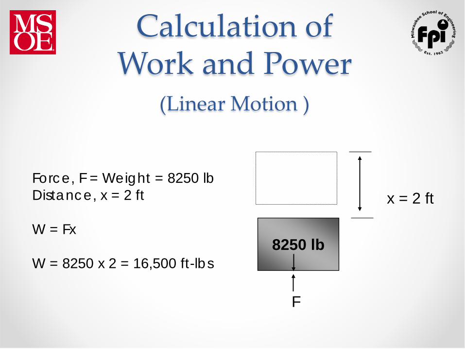
Calculation of Work and Power
(Linear Motion )
Force, F = Weight = 8250 lb Distance, x = 2 ft W = Fx W = 8250 x 2 = 16,500 ft-lbs
F
8250 lb
x = 2 ft
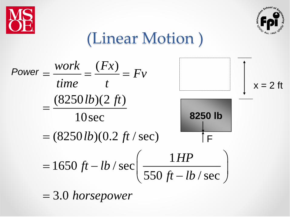
(Linear Motion )
8250 lb
x = 2 ft
F
( )
(8250 )(2 )10sec
(8250 )(0.2 / sec)
11650 / sec550 / sec
3.0
work Fx Fvtime t
lb ft
lb ft
HPft lbft lb
horsepower
= = =
=
=
= − − =
Power
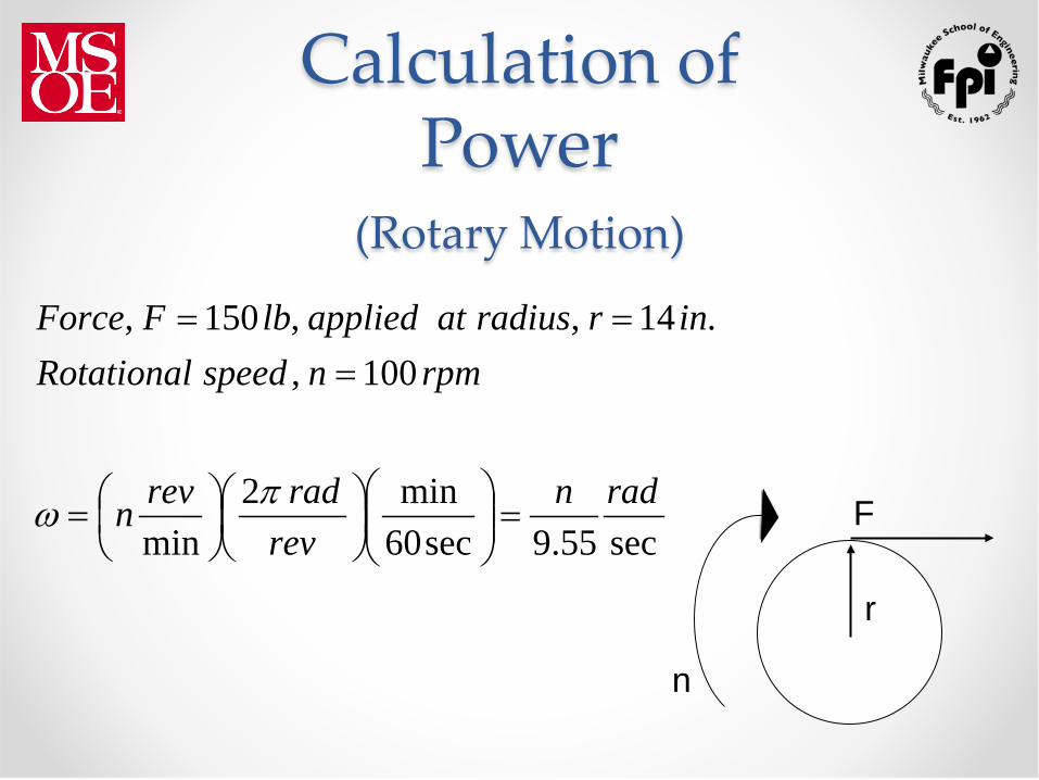
Calculation of Power
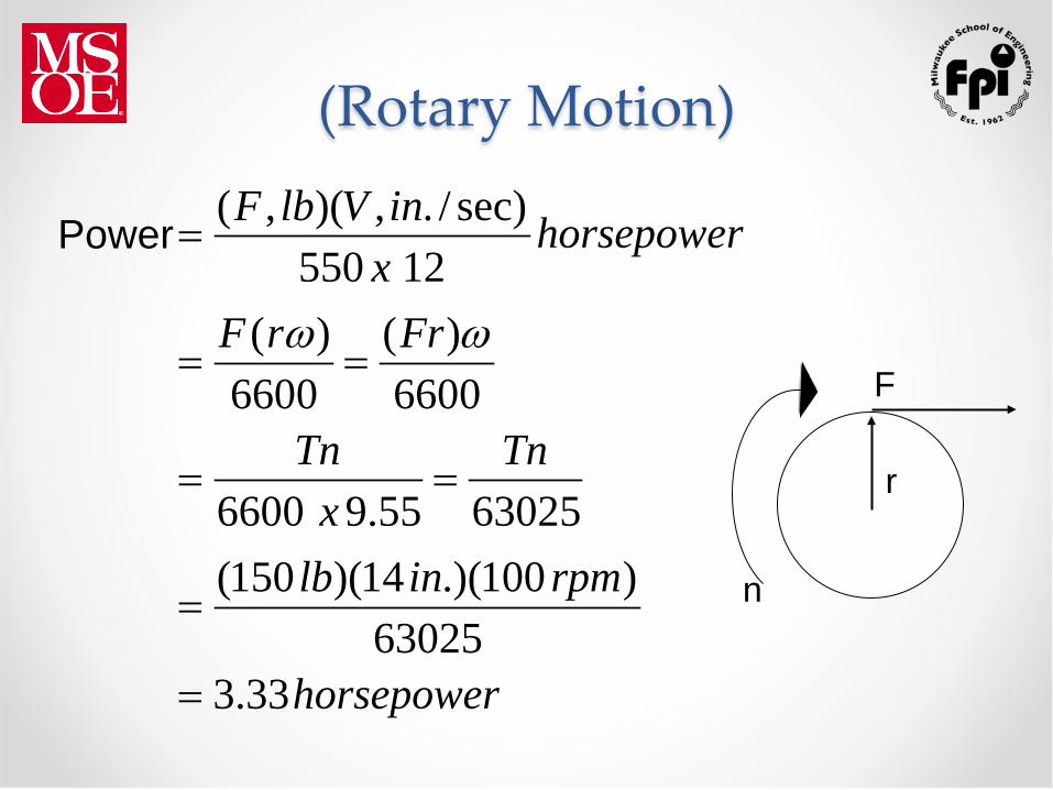
(Rotary Motion)
r
F
n
sec55.9sec60min2
min
100,.14,,150,
radnrev
radrevn
rpmnspeedRotationalinrradiusatappliedlbFForce
=
=
===
πω
(Rotary Motion)
r
F
n
horsepower
rpminlb
Tnx
Tn
FrrF
horsepowerxinVlbF
33.363025
)100.)(14)(150(6302555.96600
6600)(
6600)(
12550sec)/.,)(,(
=
=
==
==
=
ωω
Power

Block Diagram of Power Transmission System
Prime Mover
Power
Transmission Load
I-C engine Elec motor
a) mechanical b) electrical c) fluid power
push pull
rotate
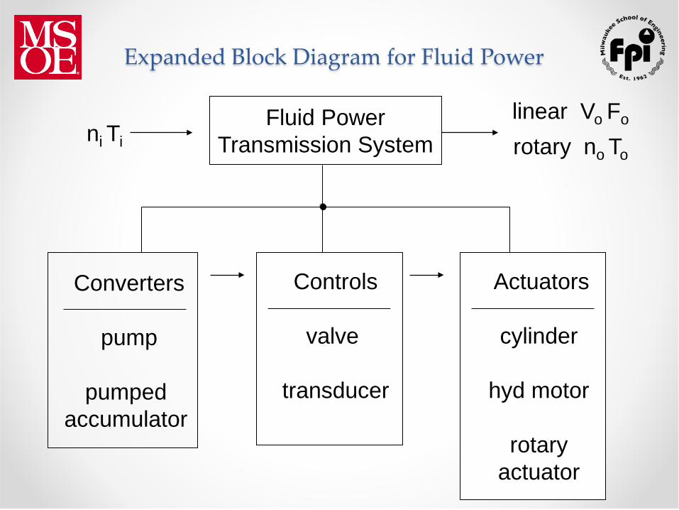
Controls
valve
transducer
Expanded Block Diagram for Fluid Power
Fluid Power Transmission System ni Ti
linear Vo Fo
rotary no To
Actuators
cylinder
hyd motor
rotary actuator
Converters
pump
pumped accumulator

Fluid Power Defined • Fluids under pressure doing work in controlled
motion • Hydraulics = liquids under pressure • Pneumatics = gasses under pressure

Work Fluid power performs work by applying
pressure against a moveable area x
F
v

Load Specifications x
F
v
F = 2750 lb
v = 0.2 ft/sec
x = 24 in.
horsepower.).)((vFHP 01550
202750550
===

Load Specifications x
F
v
The cylinder cannot be selected until the force required, the load velocity, and the distance of movement are
determined. (No work is performed if the load is stationary.)

Load Specifications x
v
If a 4-in. bore were
selected for the
cylinder…
F
2 2
2
12.574
2750 21912.57
movable area A d in
F lbp psiA in
π= = =
= = =

Load Specifications x
v
If a 2-in. bore were
selected for the
cylinder…
F
2 2
2
3.144
2750 8753.14
movable area A d in
F lbp psiA in
π= = =
= = =
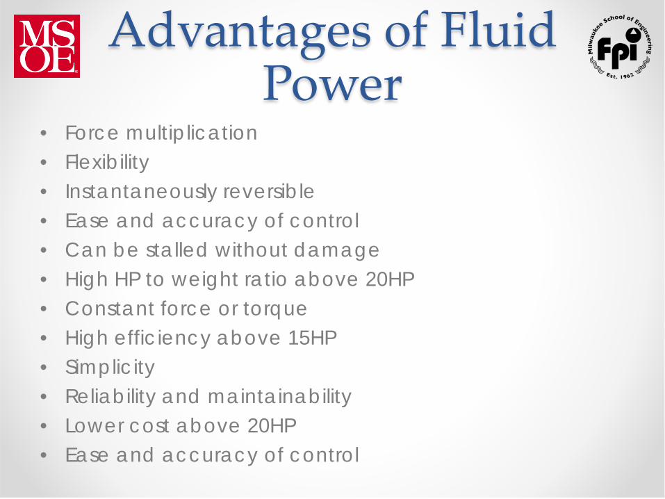
Advantages of Fluid Power
• Force multiplication • Flexibility • Instantaneously reversible • Ease and accuracy of control • Can be stalled without damage • High HP to weight ratio above 20HP • Constant force or torque • High efficiency above 15HP • Simplicity • Reliability and maintainability • Lower cost above 20HP • Ease and accuracy of control

Disadvantages of Fluid Power
• External leakage • Noise • Fire hazard With most fluids • Cost, weight, and efficiency below 15HP • Complexity and reliability

Applications of Fluid Power
• Automotive • Aerospace • Marine Industry • Materials Handling • Agricultural • Construction • Industrial Manufacturing Equipment • Primary Metals Industry

Applications of Fluid Power
• Robotics • Factory Automation Systems • Logging Industry • Transportation • Entertainment • Construction

Industrial and Mobile Hydraulic
Power Characteristics

Industrial and Mobile Hydraulic
Power Characteristics

Industry Standards • Benefits
o Interchangeability of components o Improved communication o Good engineering practice o Stimulus to product improvement o Reference source for new personnel

Industry Standards • History
o Society of Automotive Engineers (SAE) o Joint Industry Conference (JIC) o National Fluid Power Association (NFPA) o American National Standards Institute (ANSI) o International Standards Organization (ISO)

Components of a Hydraulic System
• Reservoir • Pump • Prime Mover • Valves: pressure, direction, flow • Actuator • Plumbing • Fluid conditioning

Components of a Pneumatic System
• Receiver • Compressor • Prime Mover • Valves: pressure, direction, flow • Actuator • Plumbing • Fluid conditioning

Fundamentals of Hydraulic Power Transmission

Application of Pascal’s Law
• Force equals pressure times area o F = pA
• Force multiplication in a hydraulic jack o p = F1/A1 = F2/A2 o F2 = F1(A2/A1) o Therefore, the force ratio is equal to the area ratio
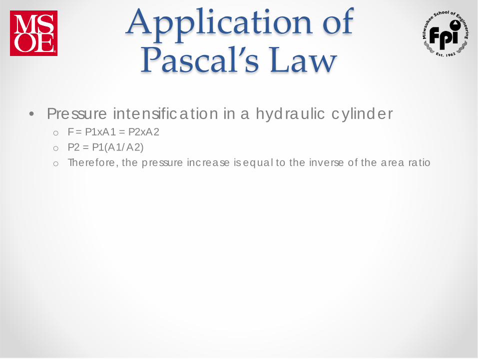
Application of Pascal’s Law
• Pressure intensification in a hydraulic cylinder o F = P1xA1 = P2xA2 o P2 = P1(A1/A2) o Therefore, the pressure increase is equal to the inverse of the area ratio

Conservation of Energy
• Energy can neither be created nor destroyed. It can only be changed from one form to another. The total energy in a system remains constant.
• Losses and inefficiencies usually show up as heat.
Types of Energy • Potential energy due to elevation above a
reference point. • Potential energy due to fluid pressure • Kinetic energy due to fluid motion

Energy Equation • The total energy at any point in a system can be
calculated using Bernoulli’s equation • This equation adds together all forms of energy at
any given point in a system • It is usually applied between two points in a system
where the energy changes from one form to another and is calculated per pound of fluid
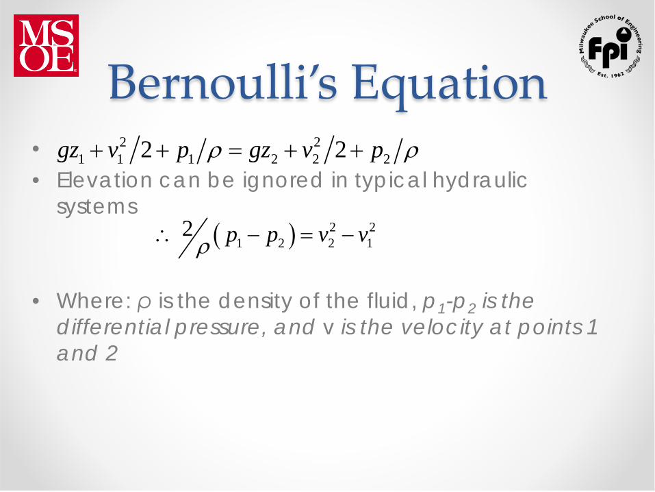
Bernoulli’s Equation • • Elevation can be ignored in typical hydraulic
systems
• Where: ρ is the density of the fluid, p1-p2 is the differential pressure, and v is the velocity at points 1 and 2
( ) 2 21 2 2 1
2 p p v vρ∴ − = −
2 21 1 1 2 2 22 2gz v p gz v pρ ρ+ + = + +

Orifice Equation • An orifice equation is derived from Bernoulli’s
equation with the following assumptions o The orifice is a small round hole on a thin wall o The orifice A <<< upstream and downstream A o The upstream velocity is negligible
• • The flow rate thru the orifice is determined using;
• Cd is used due to flow contraction and is dependent upon the orifice shape
( )2 1 22v p pρ= −
2dQ C A pρ= ∆

Continuity Equation • Volumetric flow rate
Q = A x V
• This is important for line sizing • Typical max velocity targets are:
o Pressure Line: 30 ft/sec o Return Line: 15 ft/sec o Inlet and Drain Lines: 4 ft/sec
• WHY? – Pressure drop due to friction
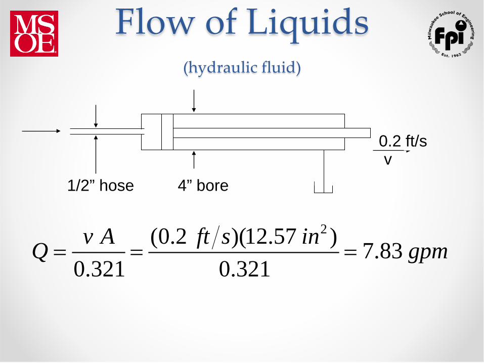
Flow of Liquids (hydraulic fluid)
v 4” bore 1/2” hose
0.2 ft/s
2(0.2 )(12.57 ) 7.830.321 0.321v A ft s inQ gpm= = =

Flow of Liquids (hydraulic fluid)
v 4” bore 1/2” hose
0.2 ft/s
2
7.830.321 0.321 12.80.196
Q gpmhose v ft sA in
= = =
In order to supply 7.83 gpm to the cylinder:

Energy and Power in Hydraulic Systems

Efficiency • Output power/Input power
o This is known as overall efficiency Eo
• Every energy converting device has an overall efficiency
• Most fluid power components have a combination of volumetric and mechanical efficiencies
Efficiency • The volumetric and mechanical efficiencies can be
combined to determine the overall efficiency • Ev x Em = Eo = HPo/HPi
• Efficiency values for individual fluid power components will be defined later
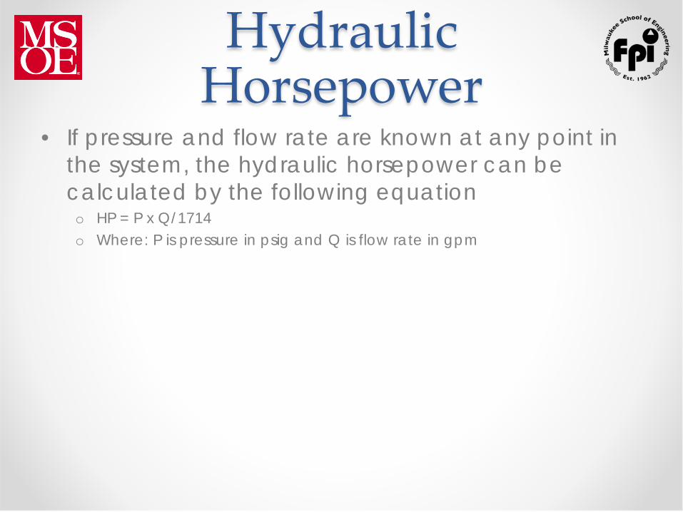
Hydraulic Horsepower
• If pressure and flow rate are known at any point in the system, the hydraulic horsepower can be calculated by the following equation o HP = P x Q/1714 o Where: P is pressure in psig and Q is flow rate in gpm
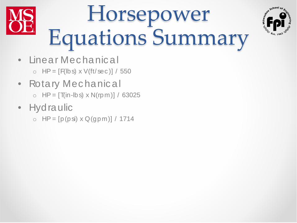
Horsepower Equations Summary
• Linear Mechanical o HP = [F(lbs) x V(ft/sec)] / 550
• Rotary Mechanical o HP = [T(in-lbs) x N(rpm)] / 63025
• Hydraulic o HP = [p(psi) x Q(gpm)] / 1714

Pascal’s Law Equations Summary
• F(lbs) = A(in2) x p(psi)
• p(psi) = F(lbs) / A(in2)
• A(in2) = F(lbs) / p(psi)

Continuity Equation Summary
• Q(gpm) = V(ft/sec) x A(in2) x 3.117
• V(ft/sec) = Q(gpm) / (A(in2) x 3.117)
• A(in2) = Q(gpm) / (V(ft/sec) x 3.117)
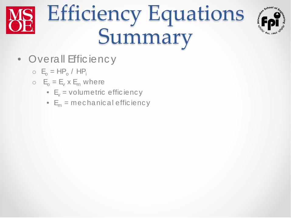
Efficiency Equations Summary
• Overall Efficiency o Eo = HPo / HPi
o Eo = Ev x Em where • Ev = volumetric efficiency • Em = mechanical efficiency

Any Questions ?
Thank You