Introduction to HVAC -...
177
VLT ® 6000 HVAC 1 MG.60.B1.02 - VLT is a registered Danfoss trademark Introduction to HVAC Contents ■ Programming All about VLT 6000 HVAC Installation Intr Intr Intr Intr Introduction to HV oduction to HV oduction to HV oduction to HV oduction to HVAC AC AC AC AC Software version .................................................................................................................. 3 Safety regulations ................................................................................................................ 4 Warning against unintended start ........................................................................................ 4 Introduction to the Design Guide ......................................................................................... 5 Available literature ................................................................................................................ 7 Why use a frequency converter for controlling ...................................................................... 8 fans and pumps? ................................................................................................................. 8 The clear advantage - energy savings .................................................................................. 8 Example with varying flow over 1 year .................................................................................. 9 Control principle ................................................................................................................ 12 PC software and serial communication .............................................................................. 15 CE-labelling ....................................................................................................................... 16 Application examples ......................................................................................................... 17 Specification text ............................................................................................................... 24 Ordering guide ................................................................................................................... 30 Choice of frequency converter ............................................................................................ 30 Unpacking and ordering a VLT frequency converter ........................................................... 34 Type code ordering number string ...................................................................................... 34 Ordering form VLT 6000 HVAC .......................................................................................... 35 Installation Installation Installation Installation Installation General technical data ....................................................................................................... 42 Mains supply 3 x 200 - 240 V ............................................................................................ 45 Technical data, mains supply 3 x 380 - 460 V .................................................................... 46 Mechanical dimensions ...................................................................................................... 48 Mechanical installation ....................................................................................................... 50 Enclosure protection .......................................................................................................... 50 Field-mounting .................................................................................................................. 50 General information about electrical installation .................................................................. 52 High voltage warning ......................................................................................................... 52 Earthing ............................................................................................................................. 52 Cables ............................................................................................................................... 52 Screened/armoured cables ................................................................................................ 52 Extra protection ................................................................................................................. 52 RFI switch ......................................................................................................................... 53 High voltage test ................................................................................................................ 53 Heat emission from VLT 6000 HVAC .................................................................................. 53 EMC-correct electrical installation ...................................................................................... 54 Use of EMC-correct cables ................................................................................................ 55 Earthing of screened/armoured control cables ................................................................... 56 VLT 6000 HVAC enclosures ............................................................................................... 57 Tightening-up torque and screw sizes ............................................................................... 62 Mains connection .............................................................................................................. 62 Pre-fuses ........................................................................................................................... 62 Motor connection .............................................................................................................. 62 DC bus connection ............................................................................................................ 64 High-voltage relay .............................................................................................................. 64 Electrical installation, control cables ................................................................................... 65 Connection example, VLT 6000 HVAC ............................................................................... 66 Switches 1-4 ..................................................................................................................... 67
Transcript of Introduction to HVAC -...

VLT® 6000 HVAC
1MG.60.B1.02 - VLT is a registered Danfoss trademark
Intr
od
ucti
on
to H
VAC
Contents
Pro
gra
mm
ing
All
abo
utV
LT 6
000
HVA
CIn
stal
lati
on
IntrIntrIntrIntrIntroduction to HVoduction to HVoduction to HVoduction to HVoduction to HVACACACACACSoftware version .................................................................................................................. 3Safety regulations ................................................................................................................ 4Warning against unintended start ........................................................................................ 4Introduction to the Design Guide ......................................................................................... 5Available literature ................................................................................................................ 7Why use a frequency converter for controlling ...................................................................... 8fans and pumps? ................................................................................................................. 8The clear advantage - energy savings .................................................................................. 8Example with varying flow over 1 year .................................................................................. 9Control principle ................................................................................................................ 12PC software and serial communication .............................................................................. 15CE-labelling ....................................................................................................................... 16Application examples ......................................................................................................... 17Specification text ............................................................................................................... 24Ordering guide ................................................................................................................... 30Choice of frequency converter ............................................................................................ 30Unpacking and ordering a VLT frequency converter ........................................................... 34Type code ordering number string ...................................................................................... 34Ordering form VLT 6000 HVAC .......................................................................................... 35
InstallationInstallationInstallationInstallationInstallationGeneral technical data ....................................................................................................... 42Mains supply 3 x 200 - 240 V ............................................................................................ 45Technical data, mains supply 3 x 380 - 460 V .................................................................... 46Mechanical dimensions ...................................................................................................... 48Mechanical installation ....................................................................................................... 50Enclosure protection .......................................................................................................... 50Field-mounting .................................................................................................................. 50General information about electrical installation .................................................................. 52High voltage warning ......................................................................................................... 52Earthing ............................................................................................................................. 52Cables ............................................................................................................................... 52Screened/armoured cables ................................................................................................ 52Extra protection ................................................................................................................. 52RFI switch ......................................................................................................................... 53High voltage test ................................................................................................................ 53Heat emission from VLT 6000 HVAC .................................................................................. 53EMC-correct electrical installation ...................................................................................... 54Use of EMC-correct cables ................................................................................................ 55Earthing of screened/armoured control cables ................................................................... 56VLT 6000 HVAC enclosures ............................................................................................... 57Tightening-up torque and screw sizes ............................................................................... 62Mains connection .............................................................................................................. 62Pre-fuses ........................................................................................................................... 62Motor connection .............................................................................................................. 62DC bus connection ............................................................................................................ 64High-voltage relay .............................................................................................................. 64Electrical installation, control cables ................................................................................... 65Connection example, VLT 6000 HVAC ............................................................................... 66Switches 1-4 ..................................................................................................................... 67

VLT® 6000 HVAC
MG.60.B1.02 - VLT is a registered Danfoss trademark2
ProgrammingProgrammingProgrammingProgrammingProgrammingControl unit LCP ................................................................................................................ 69Quick menu ....................................................................................................................... 74The Setup configuration .................................................................................................... 75Setup of user-defined readout ............................................................................................ 76Load and Motor 100-117 .................................................................................................. 81Configuration ..................................................................................................................... 81References & Limits 200 - 228 ........................................................................................... 88Reference handling ............................................................................................................ 89Inputs and outputs 300-328 ............................................................................................. 97Analogue inputs .............................................................................................................. 100Analogue/digital outputs .................................................................................................. 103Relay outputs .................................................................................................................. 106Application functions 400-427 ......................................................................................... 108Sleep mode ..................................................................................................................... 109PID for process control .................................................................................................... 113PID overview .................................................................................................................... 115Serial communication for FC protocol .............................................................................. 121Protocols ......................................................................................................................... 121Telegram communication ................................................................................................. 121Telegram build-up under FC protocol ............................................................................... 122Data character (byte) ........................................................................................................ 123Process word .................................................................................................................. 127Control word as per FC protocol ...................................................................................... 127Status word as per FC protocol ....................................................................................... 129Serial communication 500 - 556 ...................................................................................... 132Warning words 1+2 and Alarm word ................................................................................ 140Service functions 600-631 ............................................................................................... 142
All about VLAll about VLAll about VLAll about VLAll about VLT 6000 HVT 6000 HVT 6000 HVT 6000 HVT 6000 HVACACACACACStatus messages ............................................................................................................. 148List of warnings and alarms ............................................................................................. 150Aggressive environments ................................................................................................. 156Calculation of resulting reference ..................................................................................... 156Extreme running conditions ............................................................................................. 158Peak voltage on motor ..................................................................................................... 159Derating for ambient temperature ..................................................................................... 160Efficiency.......................................................................................................................... 162Definitions ....................................................................................................................... 167Factory settings ............................................................................................................... 169Index ............................................................................................................................... 175

VLT® 6000 HVAC
3MG.60.B1.02 - VLT is a registered Danfoss trademark
Intr
od
ucti
on
to H
VAC
This Design Guide can be used with all VLT 6000 HVAC fre-quency converters that have software version 1.0x.See software version number in parameter 624 Software ver-sion no.
VLT 6000 HVAC
Design GuideSoftware version: 1.0x

VLT® 6000 HVAC
MG.60.B1.02 - VLT is a registered Danfoss trademark4
Warning:Touching the electrical parts may be fatal - even after theequipment has been disconnected from mains.
Using VLT 6001-6005: wait at least 4 minutesUsing VLT 6006-6275: wait at least 15 minutes
The voltage of the frequency converteris dangerous whenever the equipmentis connected to mains. Incorrect instal-
lation of the motor or the frequency converter maycause damage to the equipment, serious personalinjury or death.Consequently, the instructions in this manual, aswell as national and local rules and safetyregulations, must be complied with.
Safety regulations1. The VLT frequency converter must be discon-
nected from mains if repair work is to be carriedout.Check that the mains supply has beendisconnected and that the necessary time haspassed before removing motor and mains plugs.
2. The [OFF/STOP] key on the control panel of theVLT frequency converter does not disconnect theequipment from mains and is thus not to be usedas a safety switch.
3. Correct protective earthing of the equipment mustbe established, the user must be protectedagainst supply voltage, and the motor must beprotected against overload in accordance withapplicable national and local regulations.
4. The earth leakage currents are higher than 3.5 mA.5. Protection against motor overload is not included
in the factory setting. If this function is required,set parameter 117, Motor thermal protection, todata value ETR trip or data value ETR warning.Note: The function is initialised at 1.0 x ratedmotor current and rated motor frequency (seepage 87).For the North American market: The ETRfunctions ensure overload protection of the motor,Class 20, in accordance with NEC.
6. Do not remove the plugs for the motor and mainssupply while the VLT frequency converter isconnected to mains. Check that the mains supplyhas been disconnected and that the necessarytime has passed before removing motor andmains plugs.
7. Reliable galvanic isolation (PELV) is not compliedwith if the RFI switch is placed in OFF position.This means that all control in- and outputs can nolonger be considered low-voltage terminals.
8. Please note that the VLT frequency converter hasmore voltage inputs than L1, L2, L3 when the DC-bus terminals are used.Check that all voltage inputs have beendisconnected and that the necessary time haspassed before repair work is commenced.
Warning against unintended start1. The motor can be brought to a stop by means of
digital commands, bus commands, references or alocal stop, while the frequency converter isconnected to mains.If personal safety considerations make itnecessary to ensure that no unintended startoccurs, these stop functions are not sufficient.
2. While parameters are being changed, the motormay start. Consequently, the stop key [OFF/STOP] must always be activated, following whichdata can be modified.
3. A stopped motor may start if a fault occurs in theelectronics of the VLT frequency converter, or if atemporary overload or a fault in the supply mainsor the motor connection ceases.

VLT® 6000 HVAC
5MG.60.B1.02 - VLT is a registered Danfoss trademark
Intr
od
ucti
on
to H
VAC
Introduction to the Design Guide
This Design Guide is a tool intended to facilitate the sizing of systems in which VLT 6000 HVAC frequencyconverters are used.HVAC stands for Heating Ventilation Air-Conditioning.
This Design Guide progresses step-by-step through the different procedures required for selecting, installing andprogramming a VLT 6000 HVAC.
The Design Guide forms part of the literature concept supplied with VLT 6000 HVAC. However, the Design Guideis the most comprehensive document available.When a VLT 6000 HVAC is supplied, it is accompanied by Operating Instructions and a Quick Setup Guide. Seenext page Other literature.
Operating Instructions:Operating Instructions:Operating Instructions:Operating Instructions:Operating Instructions: Describe how to ensure optimum mechanical and electrical installation, andalso deal with commissioning and service. The Operating Instructionsfurthermore provide a description of the software parameters, therebyensuring that you can easily fit the VLT 6000 HVAC into your application.
Quick Setup Guide:Quick Setup Guide:Quick Setup Guide:Quick Setup Guide:Quick Setup Guide: Helps you get your VLT 6000 HVAC installed and commissioned quickly.
Design Guide:Design Guide:Design Guide:Design Guide:Design Guide: Used when designing systems with VLT 6000 HVAC. The Design Guide givesall useful information about the VLT 6000 HVAC and HVAC systems. There isa selection tool for you to choose the right VLT 6000 HVAC with the relevantoptions and modules. The Design Guide has examples of the most commontypes of HVAC applications. In addition, the Design Guide has all informationrelating to Serial Communication.
This Design Guide is split in four sections that have information about VLT 6000 HVAC.
Introduction to HVAC:Introduction to HVAC:Introduction to HVAC:Introduction to HVAC:Introduction to HVAC: This section tells you the advantages that can be obtained by usingfrequency converters in HVAC systems. Furthermore, you can read about theway a frequency converter operates and about the advantages of the VLT6000 HVAC, such as AEO - Automatic Energy Optimisation, RFI filter andother HVAC-relevant functions.
There are also examples of applications and information is given aboutDanfoss and CE-labelling.
The specification section deals with the requirements relating to beingallowed to supply and install frequency converters. This section can be usedin contract documents, whereby the total list of requirements relating tofrequency converters is determined.
The section ends with an Ordering Guide that makes it easier for you tospecify and order a VLT 6000 HVAC.

VLT® 6000 HVAC
MG.60.B1.02 - VLT is a registered Danfoss trademark6
Installation:Installation:Installation:Installation:Installation: This section shows you how to carry out correct mechanical installation of aVLT 6000 HVAC.In addition, the section has a description of how you ensure that theinstallation of the VLT 6000 HVAC is EMC-correct. Furthermore, the sectionincludes a list of mains and motor connections, as well as a description ofcontrol card terminals.
Programming:Programming:Programming:Programming:Programming: This section describes the control unit and the software parameters for theVLT 6000 HVAC. There is also a guide to the Quick Setup menu, whichmeans that you will be able to start using your application very quickly.
All about VLAll about VLAll about VLAll about VLAll about VLT 6000:T 6000:T 6000:T 6000:T 6000: This section has information about status, warning and fault indications fromthe VLT 6000 HVAC. In addition, the section has technical data, serviceinformation, factory settings and information on special conditions.
Introduction to the Design Guide
This symbol indicates a generalwarning.
This symbol indicates a high-voltage warning.
This symbol indicates somethingto be noted by the reader.

VLT® 6000 HVAC
7MG.60.B1.02 - VLT is a registered Danfoss trademark
Intr
od
ucti
on
to H
VAC
Available literatureThe chart below gives an overview of the literature available for the VLT 6000 HVAC.Please note that variations may occur from one country to the next
DesignGuide
MG.60.BX.YY
OperatingInstructions
MG.60.AX.YY
Comeswith
VLT 6000HVAC
SoftwareDialog
MG.50.EX.YY
PROFIBUSManual
MG.10.EX.YYQuickSetup
MG.60.CX.YY
LCP Remotecontrol unitMI.56.AX.51
LC-filterMI.56.DX.51
IP 20 terminalcover
MI.56.CX.51
Metasys N2
VLT 6000 HVACData sheet
MD.60.AX.YY
Other literaturefor VLT 6000
HVAC
Instructionsfor VLT
6000 HVAC
Communicationwith VLT 6000
HVAC
LonWorksManual
Relay cardinstructions
MI.66.BX.YY
Landis/StaefaFLN
RCDinstructions
MI.66.AX.YY
X = version numberYY = language version01 = Danish02 = English03 = German04 = French05 = Spanish06 = Italian07 = Swedish10 = Dutch20 = Finnish28 = Brazilian-Portuguese51,52 = Danish, English, German

VLT® 6000 HVAC
MG.60.B1.02 - VLT is a registered Danfoss trademark8
Why use a frequency converter for controllingfans and pumps?A frequency converter takes advantage of the fact thatcentrifugal fans and pumps follow the laws ofproportionality for such fans and pumps.
The graph below describes the laws of proportionality.The graph shows that flow and pressure can be re-gulated by changing the rpm figure.
The laws of proportionality
This figure describes the dependence of flow, pres-sure and power consumption on the rpm figure.
Q = FlowQ1 = Rated flowQ2 = Reducing flow
H = PressureH1 = Rated pressureH2 = Reducing pressure
P = PowerP1 = Rated powerP2 = Reducing power
n = Speed regulationn1 = Rated speedn2 = Reducing speed
The clear advantage - energy savingsThe very clear advantage of using a frequency conver-ter for controlling the speed of fans or pumps lies inthe electricity savings to be obtained.When comparing with alternative regulating systemsand technologies, a frequency converter is the opti-mum energy control system for regulating fan andpump systems.
Example of energy savingsAs can be seen from the figure (the laws of propor-tionality), the flow is regulated by changing the rpmfigure. By reducing the speed only 20% from the ratedspeed, the flow is also reduced by 20%. This isbecause the flow is directly proportional to the rpmfigure. The consumption of electricity, however, isreduced by 50%.If the system in question only needs to be able tosupply a flow that corresponds to 100% a few days ina year, while the average is below 80% of the ratedflow for the remainder of the year, the amount ofenergy saved is even more than 50%.
Flow: Q1 =
n1
Pressure:H1 =
( n1 ) 2
Power:P1 =
( n1) 3
Q2 n2
H2 n2
P2 n2

VLT® 6000 HVAC
9MG.60.B1.02 - VLT is a registered Danfoss trademark
Intr
od
ucti
on
to H
VAC
Example with varying flow over 1 yearThe example below is calculated on the basis of pumpcharacteristics obtained from a pump data-sheet. (45kW). The same examples of calculations can be usedin the case of fan characteristics.The result obtained is savings in excees of 50% at the
Energy savingsThis figure compares flow regulation via valves andwithout speed control with flow regulation via afrequency converter.
Pshaft = Pshaft output
Flow distribution over 1 year
given flow distribution over a year, corresponding to8,760 hours.Typically, the example calculated below results in apay-back period of one year - depending on the priceper kWh and the price of the frequency converter.
m3/t Distribution Valve regulation Frequency converter control% Hours Power Consumption Power Consumption
A1 - B1 kWh A1 - C1 kWh350 5 438 42,5 18.615 42,5 18.615300 15 1314 38,5 50.589 29,0 38.106250 20 1752 35,0 61.320 18,5 32.412200 20 1752 31,5 55.188 10,0 17.520150 20 1752 28,0 49.056 6,5 11.388100 20 1752 23,0 40.296 3,5 6.132
ΣΣΣΣΣ 100100100100100 87608760876087608760 275.064275.064275.064275.064275.064 124.173124.173124.173124.173124.173
Pump characteristics
VLT® 6000 HVAC
MG.60.B1.02 - VLT is a registered Danfoss trademark10
Better regulationIf a frequency converter is used for regulating the flowor pressure of a system, improved regulation isobtained which can be adjusted very precisely.A frequency converter can vary the speed of the fan orpump infinitely, thereby obtaining infinitely variablecontrol of flow and pressure.Furthermore, a frequency converter can quicklyregulate the speed of the fan or pump, so as to adaptit to new flow or pressure conditions in the system.More traditional, mechanical flow or pressureregulating systems tend to provide slow, inaccurateregulation if compared with that of the frequencyconverter.
Frequency converters generate less noiseIf the speed of a fan is changed, the sound levelchanges, too. If the rpm figure is reduced by 50%from the rated rpm value, the sound level will go downby approx. 16 dB(A).The formula is:
55 log x ( ) = dB(A)
Simpler installation when using a frequency con-verterA frequency converter can replace a traditionalregulating system, in which mechanical dampers andvalves are used for regulating flow or pressure.The great advantage involved in using a frequencyconverter is that the system becomes simpler, since alot of the mechanical and electrical equipment is nolonger required.
V-belts no longer requiredIn mechanical regulating systems, where the fan isdriven by V-belts, it is necessary to change beltpulleys in order to adjust the fan speed to match theneces-sary maximum load. Using a frequency conver-ter, the V-belts can be replaced by directly driven mo-tors, whose speed is changed simply by means of thefrequency converter.The efficiency of the system improves and the entireinstallation takes up less space. There is no dust fromthe V-belt and less maintenance.
Regulating dampers and valves no longerrequiredSince the flow or pressure can be regulated bymeans of the frequency converter, no regulatingdampers and valves are required in the system.
Cos ϕϕϕϕϕ compensationGenerally speaking, a frequency converter with a cosof 1 provides power factor correction for the cos ϕ ofthe motor, which means that there is no need tomake allowance for the cos ϕ of the motor whensizing the power factor correction unit.
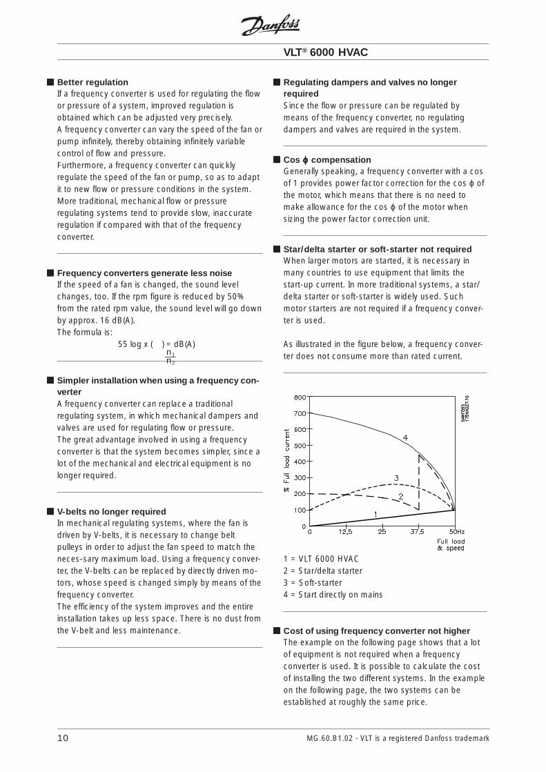
Star/delta starter or soft-starter not requiredWhen larger motors are started, it is necessary inmany countries to use equipment that limits thestart-up current. In more traditional systems, a star/delta starter or soft-starter is widely used. Suchmotor starters are not required if a frequency conver-ter is used.
As illustrated in the figure below, a frequency conver-ter does not consume more than rated current.
1 = VLT 6000 HVAC2 = Star/delta starter3 = Soft-starter4 = Start directly on mains
Cost of using frequency converter not higherThe example on the following page shows that a lotof equipment is not required when a frequencyconverter is used. It is possible to calculate the costof installing the two different systems. In the exampleon the following page, the two systems can beestablished at roughly the same price.
n1n2

VLT® 6000 HVAC
11MG.60.B1.02 - VLT is a registered Danfoss trademark
Intr
od
ucti
on
to H
VAC
WWWWWithout a frithout a frithout a frithout a frithout a frequency converterequency converterequency converterequency converterequency converterThe figure shows a fan system made in the traditionalway.
WWWWWith a frith a frith a frith a frith a frequency converterequency converterequency converterequency converterequency converterThe figure shows a fan system controlled by VLT 6000 HVAC frequency converters.
D.D.C. = Direct Digital ControlE.M.S. = Energy Management SystemV.A.V. = Variable Air VolumeSensor P = PressureSensor T = Temperature

VLT® 6000 HVAC
MG.60.B1.02 - VLT is a registered Danfoss trademark12
1. Mains voltage3 x 200 - 240 V AC, 50 / 60 Hz3 x 380 - 460 V AC, 50 / 60 Hz.
2. RectifierA three-phase rectifier bridge that rectifies ACinto DC current.
3. Intermediate circuitDC voltage = √2 x mains voltage [V].
4. Intermediate circuit coilsSmooth the intermediate circuit current and limitthe repercussive effect of harmonic currents onthe mains supply.
5. Intermediate circuit capacitorsSmooth the intermediate circuit voltage.
6. InverterConverts DC voltage into variable AC voltagewith a variable frequency.
7. Motor voltageVariable AC voltage, 10-100% of the supplyvoltage.
8. Control cardThis is where to find the microprocessor thatcontrols the inverter which generates the pulsepattern by which the DC voltage is converted intovariable AC voltage with a variable frequency.
Control principleA frequency converter rectifies AC mains voltage intoDC voltage, after which the DC voltage is converterinto an AC current with a variable amplitude andfrequency.
The motor is thus supplied with variable voltage andfrequency, which enables infinitely variable speedregulation of three phase, asynchronous standardmotors.
The development of the VVCPLUS principle is the resultof a wish to maintain robust, sensorless regulationthat is tolerant to different motor characteristicswithout motor derating being required.
First and foremost, the current measurement and themotor model have been improved. The current is splitinto magnetising and torque-generating parts andprovides for much better and quicker estimation ofthe actual motor loads. It is now possible tocompensate much better for frequent load changes.
VVCPLUS control principleThe VLT 6000 HVAC has an inverter system calledVVCPLUS, i.e. a further development of Voltage VectorControl (VVC). This principle is known from suchunits as Danfoss VLT 3500 HVAC.
VVCPLUS controls an induction motor by energizing itwith a variable frequency and a voltage that matchesit. If the motor load is changed, the magnetisationand speed of the motor change too. Consequently,the motor current is measured continuously and theactual voltage requirement and slip of the motor arecalculated from a motor model. Motor frequency andvoltage are adjusted to ensure that the motoroperating point remains optimised under varyingconditions.

VLT® 6000 HVAC
13MG.60.B1.02 - VLT is a registered Danfoss trademark
Intr
od
ucti
on
to H
VAC
Good torque control properties, smooth transition tocurrent limit operation and robust pull-out protectionare ensured.
After automatic motor adaptation, VVCPLUS will help toensure extremely accurate motor control.
Because of the good load estimation achieved, anenergy optimisation algorithm can be integrated - onethat is effective regardless of the load characteristic.
Advantages of the V V CPLUS control system:- Good compensation for step loads- Great tolerance towards varying motor
charateristics- Controlled transition from normal operation to
current limit operation (and vice versa)- Quick response from speed reference to full motor
shaft torque- Reliable pull-out torgue protection throughout the
speed range, also in the case of field weakening- Torque control, comprising control of both the
torque-generating and the magnetisingcomponent of the current
As standard, VLT 6000 HVAC comes with a numberof integral components that would normally have tobe acquired separately. These integral componentsare space-savers that simplify installation, since VLT6000 HVAC fulfills most requirements without anyadditional components.
The use of a VLT 6000 HVAC offers the followingadditional advantages:- All unit types are available with an integral RFI
filter, complying with EN 55011 class 1-A in thecase of a 150 m screened/armoured motor cableand EN 55011 class 1-B in the case of ascreened/armoured motor cable up to 50 m long.
- Detachable LCP control panel with Hand-Off-Autobuttons and a graphics display of local speed.
- Automatic Motor Adaptation (AMA) ensuresoptimum motor performance.
- Integral PID regulator with option of connectingtwo feedback signals (in connection with zoning),as well as setting of two set-points.
- Sleep mode, which automatically turns the motoroff, e.g. when there is no need for more pressureor flow in a system.
Programmable control inputs andsignal outputs in four SetupsVLT 6000 HVAC uses a digital technique whichmakes it possible to program the different controlinputs and signal outputs and to select four differentuser-defined Setups for all parameters.
For the user, it is easy to program the requiredfunctions by means of the control panel on VLT 6000HVAC or via serial communication.
Protection against mains interferenceVLT 6000 HVAC is protected against the transientsthat occur in the mains supply, e.g. when switchingpower factor correction or if fuses blow whenlightning strikes.
The rated motor voltage and full torque can bemaintained all the way down to 10% undervoltage inthe mains supply.
Minor interference on mainsSince as standard the VLT 6000 HVAC featuresintermediate circuit coils, there is only a small amountof harmonic mains supply interference. This ensures agood power factor (lower peak current), whichreduces the load on the mains installation.
- The "flying start" function enables the unit tocatch a rotating fan.
- Automatic ramp up/down to ensure that theVLT 6000 HVAC will not trip during accelerationor deceleration.
- All standard units have three integral, serialprotocols - RS 485 FC protocol, Johnson’sMetasys N2 and Landis/Staefa FLN.Communication option cards that can beconnected are LonWorks, Profibus for the VLT6000 HVAC.

VLT® 6000 HVAC
MG.60.B1.02 - VLT is a registered Danfoss trademark14
Advanced motor protectionVLT 6000 HVAC features integrated electronic,thermal motor protection.
The frequency converter calculates the motortemperature on the basis of current, frequency andtime.
As opposed to the traditional bimetallic protection,electronic protection takes account of the reductionin cooling at low frequencies that comes fromreduced fan speed (motors with internal ventilation).
Thermal motor protection is comparable to a normalmotor thermistor.
To obtain maximum protection against overheating ofthe motor if the motor is covered or blocked, or if thefan fails, a thermistor can be integrated andconnected to the thermistor input of the frequencyconverter (terminals 53/54), see parameter 117 Motorthermal protection.
Advanced VLT protectionCurrent measurement on all three motor phasesprovides perfect protection of VLT 6000 HVAC againstearthing and short-circuiting faults on the motorconnection.
Constant monitoring of the three motor phasesenables switching on the motor output, e.g. bymeans of a contactor.
Efficient monitoring of the three mains supply phasesensures that the unit trips in the case of phase failure.This avoids overloading the inverter and thecapacitors in the intermediate circuit, which woulddramatically reduce the service life of the frequencyconverter.
As standard, VLT 6000 HVAC features integraltemperature protection. If a thermal overload occurs,this function cuts out the inverter.
Reliable galvanic isolationIn the VLT 6000 HVAC, all control terminals as well asterminals 1-5 (AUX relays) are supplied by orconnected to circuits that comply with PELVrequirements in relation to the mains potential.
AEO - Automatic Energy OptimizationNormally, the U/f characteristics have to be set on thebasis of the expected load at different frequencies.However, knowing the load at a given frequency in aninstallation is often a problem. This problem can besolved by using a VLT 6000 HVAC with its integralAutomatic Energy Optimization (AEO), which ensuresoptimum energy utilization. All VLT 6000 HVAC unitsfeature this function as a factory setting, i.e. it is notnecessary to adjust the frequency converter U/f ratioin order to obtain maximum energy savings. In otherfrequency converters, the given load and voltage/frequency ratio (U/f) must be assessed to carry outcorrect setting of the frequency converter.Using Automatic Energy Optimization (AEO), you nolonger need to calculate or assess the systemcharacteristics of the installation, since Danfoss VLT6000 HVAC units guarantee optimum, load-dependent energy consumption by the motor at alltimes.
The figure illustrates the working range of the AEOfunction, within which energy optimization is enabled.
If the AEO function has been selected in parameter101, Torque characteristics, this function will beconstantly active. If there is a major deviation from theoptimum U/f ratio, the VLT frequency converter willquickly adjust itself.
Advantages of the AEO function• Automatic energy optimization• Compensation if an oversize motor is used• AEO matches operations to daily or seasonal
fluctuations• Energy savings in a constant air volume system• Compensation in the oversynchronous working
range• Reduces acoustic motor noise

VLT® 6000 HVAC
15MG.60.B1.02 - VLT is a registered Danfoss trademark
Intr
od
ucti
on
to H
VAC
PC software and serial communicationDanfoss offers various options for serial communi-cation. Using serial communication makes it possibleto monitor, programme and control one or several VLT6000 HVAC from a centrally placed computer. Forexample, Danfoss offers an option card for Profibus.In addition, all VLT 6000 HVAC have an RS 485 portas standard, which enables them to communicatee.g. with a PC. A programme entitled VLT SoftwareDialog is available for this purpose.
VLT Software Dialog comes in three modules and - asa minimum - contains the programmes included inthe Basic module.
The Basic module covers:
TEST RUNis used for controlling and commissioning ofa frequency converter, including:- setting of reference value,- simultaneous display of selected
parameters in graphs,- option of DDE link, e.g. to a spreadsheet.
PARAMETER SETUPis used for setting up and transferring para-meter sets, including:- setting of frequency converter parameters,- parameter sets can be obtained from and
copied to a frequency converter,- documentation/print-out of the Setup
including diagrams.
HISTORYprovides information about the differentstages of development of the VLT Softwaredialogue.
BUS ADDRESS SETUPis only used for addressing the VLT FCM.
The Logging module covers:
LOGGINGis used for collecting and displaying historical orreal-time operating data.- graphical representation of selected
parameters from several frequencyconverters,
- collection of log data to file,- option of DDE link e.g. to a spreadsheet.
MODEM SETUPis used for setting up the frequency convertermodem.- sets the frequency converter modem via the
communication port of the PC.
The template module covers:
TEMPLATE SETUPis used for setting up template files forPARAMETER SETUP:- the template file functions as a mask that
limits the number of accessible parameterswhen a parameter file is to be made or editedin PARAMETER SETUP,
- the template file may contain preset values for
the parameters of the frequency converter.
NB!The logging and template module calls for aBasic module to be installed on the same PC.
The guided tour covers:
GUIDED TOURoffers a demonstration of the VLT SoftwareDialog programme.

VLT® 6000 HVAC
MG.60.B1.02 - VLT is a registered Danfoss trademark16
CE-labellingWhat is CE-labelling ?What is CE-labelling ?What is CE-labelling ?What is CE-labelling ?What is CE-labelling ?The purpose of CE-labelling is to avoid technicalobstacles to trade within EFTA and the EU. The EUhas introduced the CE-label as a simple way ofshowing whether a product complies with therelevant EU directives. The CE-label says nothingabout the quality or specifications of a product.Three EU directives relate to frequency converters:
••••• The machine directive (89/392/EEC)The machine directive (89/392/EEC)The machine directive (89/392/EEC)The machine directive (89/392/EEC)The machine directive (89/392/EEC)All machines with critical, moving parts arecomprised by the machine directive whichcame into force on 1 January 1995. Since afrequency converter is largely electrical byfunction, it does not fall under the machinedirective. However, if a frequency converter issupplied for use in a machine, we provideinformation about the safety aspects relatingto the frequency converter. We do that bymeans of a manufacturer’s declaration.
••••• The low voltage directive (73/23/EEC)The low voltage directive (73/23/EEC)The low voltage directive (73/23/EEC)The low voltage directive (73/23/EEC)The low voltage directive (73/23/EEC)Frequency converters must be CE-labelled inaccordance with the low voltage directivewhich came into force on 1 January 1997.This directive applies to all electricalequipment and units used in the 50-1000 VAC and 75-1500 V DC voltage ranges.Danfoss provides its units with CE-labels inaccordance with the directive and issuesdeclarations of conformity upon request.
••••• The EMC directive (89/336/EEC)The EMC directive (89/336/EEC)The EMC directive (89/336/EEC)The EMC directive (89/336/EEC)The EMC directive (89/336/EEC)
EMC is short for electromagnetic compatibility.The presence of electromagnetic compatibilitymeans that the mutual interference betweendifferent components/appliances is so small thatthe functioning of the appliances is not affected.The EMC directive came into force on 1 January1996. In accordance with the directive, DanfossCE-labels its products and issues a declarationof conformity upon request.
To help ensure that your installation is EMC-correct,the manual provides detailed instructions forinstallation. Furthermore, we specify which normsthat are complied with by which of our products. Weoffer the filters that can be seen from thespecifications and gladly provide other types ofassistance that can help you obtain the best possibleEMC result.
In most cases the VLT frequency converter is used byprofessionals of the trade as a complex componentforming part of a larger appliance, system orinstallation. It must be noted that the responsibility forthe final EMC properties of the appliance, system orinstallation rests with the installer.

VLT® 6000 HVAC
17MG.60.B1.02 - VLT is a registered Danfoss trademark
Intr
od
ucti
on
to H
VAC
Application examplesThe next few pages give typical examples ofapplications within HVAC.If you would like to receive further information about agiven application, please ask your Danfoss supplierfor an information sheet that gives a full description ofthe application.
Variable Air Volume ........................................................................................................ page 18Ask for The Drive to...Improving Variable Air Volume Ventilation systems MN.60.A1.02
Constant Air Volume ....................................................................................................... page 19Ask for The Drive to...Improving Constant Air Volume Ventilation systems MN.60.B1.02
Cooling Tower Fan .......................................................................................................... page 20Ask for The Drive to...Improving fan control on cooling towers MN.60.C1.02
Condenser pumps ......................................................................................................... page 21Ask for The Drive to...Improving condenser water pumping systems MN.60.F1.02
Primary pumps ............................................................................................................... page 22Ask for The Drive to...Improve your primary pumping in primay/secondarypumping systems MN.60.D1.02
Secondary pumps.......................................................................................................... page 23Ask for The Drive to...Improve your secondary pumping in primay/secondarypumping systems MN.60.E1.02

VLT® 6000 HVAC
MG.60.B1.02 - VLT is a registered Danfoss trademark18
Variable Air VolumeVAV or Variable Air Volume systems, are used tocontrol both the ventilation and temperature to satisfythe requirements of a building. Central VAV systemsare considered to be the most energy efficientmethod to air condition buildings. By designingcentral systems instead of distributed systems, agreater efficiency can be obtained.The efficiency comes from utilizing larger fans andlarger chillers which have much higher efficienciesthan small motors and distributed air-cooled chillers.Savings are also seen from the decreased main-tenance requirements.
The new standardWhile dampers and IGVs work to maintain a constantpressure in the ductwork, a VLT frequency convertersolution saves much more energy and reduces thecomplexity of the installation. Instead of creating anartificial pressure drop or causing a decrease in fanefficiency, the VLT frequency converter decreases thespeed of the fan to provide the flow and pressurerequired by the system.Centrifugal devices such as fans behave according tothe centrifugal laws. This means the fans decreasethe pressure and flow they produce as their speed isreduced. Their power consumption is therebysignificantly reduced.
The return fan is frequently controlled to maintain afixed difference in airflow between the supply andreturn. The advanced PID controller of the VLT 6000HVAC can be used to eliminate the need for addi-tional controllers.
Pressuresignal
VAV boxes
Flow
Flow
Cooling coil Heating coil
D1
D2
D3
Filter
Pressuretransmitter
Supply fan
Return fan
T
3
3

VLT® 6000 HVAC
19MG.60.B1.02 - VLT is a registered Danfoss trademark
Intr
od
ucti
on
to H
VAC
Constant Air VolumeCAV, or Constant Air Volume systems are centralventilation systems usually used to supply largecommon zones with the minimum amounts of freshtempered air. They preceded VAV systems andtherefore are found in older multi-zoned commercialbuildings as well. These systems preheat amounts offresh air utilizing Air Handling Units (AHUs) with aheating coil, and many are also used to air conditionbuildings and have a cooling coil. Fan coil units arefrequently used to assist in the heating and coolingrequirements in the individual zones.
The new standardWith a VLT frequency converter, significant energysavings can be obtained while maintaining decentcontrol of the building. Temperature sensors or CO2sensors can be used as feedback signals to VLTfrequency converters. Whether controllingtemperature, air quality, or both, a CAV system can becontrolled to operate based on actual buildingconditions. As the number of people in the controlledarea decreases, the need for fresh air decreases. TheCO2 sensor detects lower levels and decreases thesupply fans speed. The return fan modulates tomaintain a static pressure setpoint or fixed differencebetween the supply and return air flows.
Several features of Danfoss HVAC dedicated VLTfrequency converter, the VLT 6000 HVAC can beutilized to improve the performance of your CAVsystem. One concern of controlling a ventilationsystem is poor air quality. The programmableminimum frequency can be set to maintain a minimumamount of supply air regardless of the feedback orreference signal. The VLT frequency converter alsoincludes a two zone, 2 setpoint PID controller whichallows monitoring both temperature and air quality.Even if the temperature requirement is satisfied, thedrive will maintain enough supply air to satisfy the airquality sensor. The controller is capable of monitoringand comparing two feedback signals to control thereturn fan by maintaining a fixed differential air flowbetween the supply and return ducts as well.
With temperature control, especially used in airconditioning systems, as the outside temperaturevaries as well as the number of people in thecontrolled zone changes, different cooling require-ments exist. As the temperature decreases below thesetpoint, the supply fan can decrease its speed. Thereturn fan modulates to maintain a static pressuresetpoint. By decreasing the air flow, energy used toheat or cool the fresh air is also reduced, addingfurther savings.
Pressuresignal
Cooling coil Heating coil
D1
D2
D3
Filter
Pressuretransmitter
Supply fan
Return fan
Temperaturesignal
Temperaturetransmitter

VLT® 6000 HVAC
MG.60.B1.02 - VLT is a registered Danfoss trademark20
Water Inlet
Water Outlet
CH
ILLE
R
TemperatureSensor
BASIN ConderserWater pump
Supply
Cooling Tower FanCooling Tower Fans are used to cool condenserwater in water cooled chiller systems. Water cooledchillers provide the most efficient means of creatingchilled water. They are as much as 20% more efficientthan air cooled chillers. Depending on climate,Cooling towers are often the most energy efficientmethod of cooling the condenser water from chillers.They cool the condenser water by evaporation.The condenser water is sprayed into the coolingtower onto the cooling towers “fill” to increase itssurface area. The tower fan blows air through the filland sprayed water to aid in the evaporation.Evaporation removes energy from the water droppingits temperature. The cooled water collects in thecooling towers basin where it is pumped back intothe chillers condenser and the cycle is repeated.
The new standardWith a VLT frequency converter, the cooling towersfans can be controlled to the required speed tomaintain the condenser water temperature. VLTfrequency converters can also be used to turn the fanon and off as needed.
Several features of Danfoss HVAC dedicated drive, theVLT 6000 HVAC can be utilized to improve theperformance of your cooling tower fans application.As the cooling tower fans drop below a certain speed,the effect the fan has on cooling the water becomessmall. Also, when utilizing a gear-box to VLTfrequency converter the tower fan, a minimum speedof 40-50% may be required.The customer programmable minimum frequencysetting of the VLT is available to maintain thisminimum frequency even as the feedback or speedreference calls for lower speeds.
Also as a standard feature, you can program the VLTfrequency converter to enter a “sleep” mode and stopthe fan until a higher speed is required. Additionally,some cooling tower fans have undesireablefrequencies that may cause vibrations. Thesefrequencies can easily be avoided by programming thebypass frequency ranges in the VLT frequencyconverter.

VLT® 6000 HVAC
21MG.60.B1.02 - VLT is a registered Danfoss trademark
Intr
od
ucti
on
to H
VAC
Water Inlet
Water Outlet
CH
ILLE
R
BASIN
ConderserWater pump
Supply
Temperaturesensor
Condenser pumpsCondenser Water pumps are primarily used tocirculate water through the condenser section ofwater cooled chillers and their associated coolingtower. The condenser water absorbs the heat fromthe chillers condenser section and releases it into theatmosphere in the cooling tower. These systems areused to provide the most efficient means of creatingchilled water, they are as much as 20% more efficientthan air cooled chillers.
The new standardVLT frequency converters can be added to conden-ser water pumps instead of balancing the pumpswith a throttling valve, to control the water tempera-ture instead of tower fans, or to control the watertemperature in addition to controlling the tower fans.
Using a VLT frequency converter instead of athrottling valve simply saves the energy that wouldhave been absorbed by the valve. This can amount tosavings of 15-20% or more. VLT frequencyconverters are used to control the water temperatureinstead of controlling the cooling tower fans when itis more convenient to access the pumps than thetower fans.
Pump control is used in conjunction with fan controlto control the water temperature in free coolingapplications or when the cooling towers are signi-ficantly oversized. In some circumstances theenvironment itself causes the water to become toocool even when the fan is off. The VLT frequencyconverter controlled pump maintains the appropriatetemperature by increasing or decreasing thedischarge pressure and flow rate. The decreasedpressure at the spray nozzle in the cooling towerdecreases the surface area of the water exposed tothe air. Cooling is decreases and the design tempe-rature can be maintained in periods of low loads.

VLT® 6000 HVAC
MG.60.B1.02 - VLT is a registered Danfoss trademark22
Primary pumpsPrimary pumps in a primary/secondary pumpingsystem can be used to maintain a constant flowthrough devices that encounter operation or controldifficulties when exposed to variable flow. The primary/secondary pumping technique decouples the“primary” production loop from the “secondary”distribution loop. This allows devices such as chillersto obtain constant design flow and operate properlywhile allowing the rest of the system to vary in flow.
As the evaporator flow rate decreases in a chiller, thechilled water begins to become over-chilled. As thishappens, the chiller attempts to decrease its coolingcapacity. If the flow rate drops far enough, or tooquickly, the chiller cannot shed its load sufficiently andthe chiller’s low evaporator temperature safety tripsthe chiller requiring a manual reset. This situation iscommon in large installations especially when two ormore chillers in parallel are installed if primary/secondary pumping is not utilized.
The new standardDepending on the size of the system and the size ofthe primary loop, the energy consumption of theprimary loop can become substantial.A VLT frequency converter can be added to theprimary system, to replace the throttling valve and/ortrimming of the impellers, leading to reducedoperating expenses. Two control methods arecommon:
The first method uses a flow meter. Because thedesired flow rate is known and is constant, a flowmeter can be installed at the discharge of each chillercan be used to control the pump directly. Using thebuilt-in PID controller, the VLT frequency converterwill always maintain the appropriate flow rate, evencompensating for the changing resistance in theprimary piping loop as chillers and their pumps arestaged on and off.
The other method is local speed determination. Theoperator simple decreases the output frequency untilthe design flow rate is achieved.Using a VLT frequency converter to decrease thepumps speed is very similar to trimming the pumpsimpeller, except it doesn’t require any labor and thepumps efficiency remains higher. The balancingcontractor simply decreases the speed of the pumpuntil the proper flow rate is achieved and leaves thespeed fixed. The pump will operate at this speed anytime the chiller is staged on. Because the primaryloop doesn’t have control valves or other devices thatcan cause the system curve to change and thevariance due to staging pumps and chillers on and offis usually small, this fixed speed will remainappropriate. In the event the flow rate needs to beincreased later in the systems life, the VLT frequencyconverter can simply increase the pumps speedinstead of requiring a new pump impeller.
CH
ILLE
R
F
CH
ILLE
R
F
Flowmeter Flowmeter

VLT® 6000 HVAC
23MG.60.B1.02 - VLT is a registered Danfoss trademark
Intr
od
ucti
on
to H
VAC
Secondary pumpsSecondary pumps in a primary/secondary chilledwater pumping system are used to distribute thechilled water to the loads from the primary productionloop. The primary/secondary pumping system is usedto hydronically decouple one piping loop fromanother. In this case. The primary pump is used tomaintain a constant flow through the chillers whileallowing the secondary pumps to vary in flow,increase control and save energy.If the primary/secondary design concept is not usedand a variable volume system is designed, when theflow rate drops far enough or too quickly, the chillercannot shed its load properly. The chiller’s lowevaporator temperature safety then trips the chillerrequiring a manual reset. This situation is common inlarge installations especially when two or more chillersin parallel are installed.
The new standardWhile the primary-secondary system with two-wayvalves improves energy savings and eases systemcontrol problems, the true energy savings and con-trol potential is realized by adding VLT frequencyconverters.With the proper sensor location, the addition of VLTfrequency converters allows the pumps to vary theirspeed to follow the system curve instead of the pumpcurve.This results in the elimination of wasted energy andeliminates most of the over-pressurization the two-way valves can be subjected too.As the monitored loads are satisfied, the loads two-way valves close down. This increases the differentialpressure measured across the load and two-wayvalve. As this differential pressure starts to rise, thepump is slowed to maintain the control head alsocalled setpoint value. This setpoint value is calculatedby summing the pressure drop of the load and twoway valve together under design conditions.
NB!Please note that when running multiplepumps in parallel, they must run at the same
speed to maximize energy savings, either withindividual dedicated drives or one drive runningmultiple pumps in parallel.
CH
ILLE
R
CH
ILLE
R
∆P
3
3

VLT® 6000 HVAC
MG.60.B1.02 - VLT is a registered Danfoss trademark24
Specification textThe following is a proposal for a HVAC frequencyconverter specification text that can be supplied withtender material.
Part 1 General
1.01 Section IncludesA. This section covers the requirements necessary to
furnish and install frequency converters.
1.02 Related WorkA. This section shall be used in conjunction with the
following other specifications and related ContractDocuments to establish the total requirements forfrequency converters:1) Section 16000 - Basic ElectricalRequirements
B. In the event of conflicts regarding frequencyconverter requirements between this section andany other section, the provision of this sectionshall govern.
1.03 ReferencesEach frequency converter shall be designed andmanufactured in accordance with the current editionof the following European and international standardsand directives:A. EN 55011 - Limits and methods of measurement
of radio disturbance characteristics (EMCEmmision)
B. EN 50178 - Electronic equipment for use in PowerInstallations
C. EN 61800-3 - Adjustable speed electrical powerdrive systems - Part 3: EMC product standard
D. EN 61000-3-2 - Limits for harmonic currentemissions (equipment input current below 16 Aper phase)
E. prEN 61000-3-4 - Limits for harmonic currentemissions (equipment input current above 16 Aper phase)
F. ENV 50140 - EMC/Radiated radio frequencyelectrical field (simulation of impact from GSMtelephones)
G. EMC Directive 89/336/EECH. Low Voltage Directive 73/23/EECI. EN 50082-2 - Generic Immunity, IndustryJ. EN/IEC 61000-4-2 - ElectroStatic Discharge (EMC
Immunity)K. EN/IEC 61000-4-3 - Radiated electromagnetic
field (EMC Immunity)
L. EN/IEC 61000-4-4 - Burst (EMC Immunity)M. EN/IEC 61000-4-5 - Surge (EMC Immunity)N. EN/IEC 61000-4-6 - Cable born HF (EMC
Immunity)O. VDE 0160 class W2 test pulse - Mains transients
(EMC Immunity)P. UK Electricity Council Recommendation G5/3
Stage 2 (EMC Emission)Q. IEEE 519: 1992 - Harmonic Control in Electrical
Power SystemsR. UL 508S. US National Electric Code (NEC)T. Canadian Underwriters Laboratory (C-UL).
1.04 Design CriteriaA. The frequency converter shall be designed for
HVAC applications.B. The frequency converter shall be of the pulse
width modulated voltage vector control type.C. The frequency converter shall be able to operate
any asynchronous AC motor with a variabletorque load.
1.05 Regulatory RequirementsA. The frequency converters must be CE marked in
accordance with the EMC Directive 89/336/EECand the Low Voltage Directive 73/23/EEC.
B. A Manufacturers Declaration must be issued inaccordance with the Machine Directive 89/392/EEC.
C. Conducted Radio Frequency Interference (RFI)shall be in accordance with EN 55011 Group 1Class B with built-in RFI filters.
D. The Total Harmonic Voltage Distortion in theelectrical power system shall not exceed 5% at thePoint of Common Coupling (transformersecondary side).
E. The frequency converter immunity shall be inaccordance with EN 50082-2.
F. The manufacturer shall be certified in accordancewith ISO 14001: 1996 EnvironmentalManagement Systems.

VLT® 6000 HVAC
25MG.60.B1.02 - VLT is a registered Danfoss trademark
Intr
od
ucti
on
to H
VAC
1.06 Quality AssuranceA. The frequency converters shall be manufactured in
accordance with ISO 9001: 1994 Quality Systems.B. To ensure quality and minimize failures at the
jobsite, every frequency converter shall be testedby the manufacturer. The frequency converter shalloperate a dynamometer at full load and the loadand speed shall be cycled during the test.
C. All optional features shall be functionally tested atthe factory for proper operation.
1.07 SubmittalsA. Submit manufacturer's performance data
including:1) dimensional drawings2) power circuit diagrams3) installation and maintenance manuals4) warranty description5) frequency converter's full load ampere rating6) UL certification agency file numbers7) catalog information
B. The specification lists the minimum frequencyconverter performance requirements for thisproject. Each supplier shall list any exceptions tothe specification. If no departures from thespecification are identified, the supplier shall bebound by the specification.
C. The frequency converter manufacturer shall carryout a harmonics study to determine compliancewith the standards listed under1.03 References at the Point of Common Couplingprior to commencement of contract. Datanecessary to perform the study will be madeavailable to the manufacturer.
Part 2 Products
2.01 ManufacturersDanfoss VLT® 6000 HVACGraham VLT® 6000 Series
2.02 GeneralA. Furnish complete frequency converters as
specified herein for the fans and pumpsdesignated on the drawing schedules to bevariable speed. All standard and optional featuresshall be included within the frequency converterenclosure, unless otherwise specified.
B. All drive adjustments and programming shall becapable of being stored in non-volatile memory(EEPROM).
C. Operating frequency shall be limited to zero to 120Hz
D. Active current limit function to provide nominal 110percent torque for 1 minute.
2.03 MechanicalA. Frequency converters shall be housed in a metal IP
54 enclosure in accordance with IEC 529.
2.04 ElectricalA. The frequency converter shall convert incoming
fixed frequency three-phase AC power into avariable frequency and voltage for controlling thespeed of three phase AC motors. The motorcurrent shall closely approximate a sine wave.Motor voltage shall be varied with frequency tomaintain desired motor magnetization currentsuitable for centrifugal pump and fan control.
B. An advanced sine wave approximation and voltagevector control shall be used to allow operation atrated motor shaft output at nominal speed with noderating. This voltage vector control shall minimizeharmonics to the motor to increase motorefficiency and life.

VLT® 6000 HVAC
MG.60.B1.02 - VLT is a registered Danfoss trademark26
2.05 Protective FeaturesA. Class 20 I2t electronic motor overload protection
for single motor applications and thermal-mechanical overloads for multiple motorapplications.
B. Protection against input transients, loss of AC linephase, short circuit, ground fault, overvoltage,undervoltage, frequency converterovertemperature and motor overtemperature. Thefrequency converter shall display all faults in plaintext. Codes are not acceptable.
C. Protection of frequency converter from sustainedpower or phase loss. The frequency convertershall incorporate a 300 msec control power lossride through to eliminate nuisance tripping.
D. The frequency converter shall incorporate a motorpreheat circuit to keep the motor warm andprevent condensation build up in the stator.
E. The frequency converter shall incorporate a runpermissive function, which will exports a "runpermissive standby" signal to a digital output,when a start signal is applied to the frequencyconverter. The frequency converter must not startuntil it receives a "ready" signal from an externalcontact.
F. The frequency converter shall incorporate 4 skipfrequencies with adjustable bandwidth, to preventmechanical resonances from destroying theequipment.
G. To prevent breakdown of the motor windinginsulation, the UPEAK must be below 1000 V. Thesupplier shall include with the quotation the UPEAK
values of the frequency converter.H. The frequency converter shall catch a rotating
motor operating forward or reverse up to fullspeed to prevent nuisance tripping.
I. A thermistor input must be available in thefrequency converter.
J. The frequency converter shall incorporateconstant torque start to prevent nuisance tripping.
K. Automatic adjustment of the ramp time, to preventtripping, must be incorporated in the frequencyconverter.
C. The frequency converter shall include AutomaticMotor Adaptation (AMA), to optimize motorperformance, improve start capabilities andcompensate for motor cable variances. AMA shallbe carried out at motor standstill with no need fordetaching the load from the motor.
D. The frequency converter and options shall betested to ANSI/UL Standard 508. The completefrequency converter, including all specifiedoptions, shall be listed by a nationally recognizedtesting agency such as UL, C-UL, ETL or CSA.
E. The frequency converter shall have a DC linkreactor integrated to minimize power lineharmonics. There shall be reactors in both thepositive and negative rails. Frequency converterswithout a DC link reactor shall provide 3%impedance AC line reactors.
F. The frequency converter's full load amp ratingshall meet or exceed NEC Table 430-150.
G. The frequency converter shall be able to providefull rated output current continuously, 110% ofrated current for 60 seconds and 160% torque forup to 5 seconds for high inertia and high frictionloads.
H. An automatic energy optimization feature shall beprovided as standard in the frequency converter.This feature shall reduce voltages when the motoris lightly loaded and minimise the motor losses.
I. For additional energy savings the frequencyconverter must be able to turn itself off, whenoperation does not serve a purpose as determinedby the control signal. To prevent the frequencyconverter from turning on and off all the time, aBoost setpoint must be selectable.
J. The frequency converter fan must automaticallyturn off at low temperatures.
K. Unlimited output power circuit switching must bepossible without the need for control circuitinterlocking and without causing damage to thefrequency converter.

VLT® 6000 HVAC
27MG.60.B1.02 - VLT is a registered Danfoss trademark
Intr
od
ucti
on
to H
VAC
2.06 ControlA. Hand/Off/Auto selector switches shall be provided
on the keypad to start and stop the frequencyconverter. It must be possible to select local andremote reference independant of Hand/Off/Auto.The local speed reference must be adjustable fromthe keypad.
B. Digital manual speed control. Potentiometers arenot acceptable.
C. Provide a 24 V DC, 40 mA max, output signal toindicate that the frequency converter is in Automode.
D. Lockable, alphanumeric backlit display keypad canbe remotely mounted up to 3 meters away.
E. It must be possible to read 4 operatingparameters on the display at the same time.
F. It shall be possible to upload the frequencyconverter settings in the keypad, to allowprogramming of other drives throughdownloading of parameters. Upload/downloadmust be possible between any frequencyconverter size.
G. Frequency converters up to 200 kW shall use thesame control panel.
H. Displays shall be available in 9 languagesincluding English, Spanish, German and French.
I. A red FAULT light, a yellow WARNING light and agreen POWER-ON light shall be provided.
J. A Quick Setup menu with preset parameters shallbe provided for easy pre-commissioning.
K. It must be possible to connect an external key-lock to the frequency converter, to preventunauthorised programming.
L. The frequency converter shall be equipped with aRS 485 serial communication port and besupplied with software to display all monitoring,fault, alarm and status signals. The software shallallow parameter changes to be made to thefrequency converter settings as well as storage ofeach controller's operating and Setup parameters.The protocol must be selectable. Choices mustinclude Danfoss FC protocol, Johnson ControlsMetasys N2, Landis-Staefa FLN.
M. A LonMark certified option must be available forthe frequency converter, to secure easyimplementation in a LonWorks network.
N. It must be possible to program a text string in thefrequency converter display.
O. PID controller shall be standard in the unit.Programming must be done in process units(including: Pa, MPa, mbar, inWG, ftWG, m3/h, m3/s, GPM, CFM, °C and °F).
P. It shall be possible to program a feedbackconversion, such that the frequency converterinterprets a pressure as a flow. This must beaccomplished by a automatic conversion of thesquared pressure signal into a linear flow signal.
Q. A low pass filter must be supplied with the PIDcontroller.
R. The PID controller shall be able to accept twofeedback signals and two setpoints. Response tothe setpoint/feedback differences must beprogramable.
S. It must be possible to increase/decrease speed inresponse to digital signals.
T. An elapsed time meter and kWh meter shall beprovided.
U. The following displays shall be accessible from thecontrol panel in actual units: Local and RemoteReference Signal Percent, Output Frequency,Output Amps, Motor HP, Motor kW, kWh, OutputVoltage, No Load Warning, DC Bus Voltage,frequency converter Temperature (in °C) andMotor Speed in engineering units per application(in percent speed, RPM).
L. Autoderating of the maximum drive current shallbe incorporated in the frequency converter, toallow continued operation at reduced speed, incase of an overtemperature, phase loss or mainsimbalance, without damaging the frequencyconverter.
M. Full galvanic isolation with suitable potentialseparation from the power sources to ensurecompliance with the PELV requirements ofEN 50178.

VLT® 6000 HVAC
MG.60.B1.02 - VLT is a registered Danfoss trademark28
V. The frequency converter will sense the loss of loadand signal a no load/broken belt warning or fault.
W. The frequency converter shall store in memory thelast 10 faults and record all operational data.
X. Eight programmable digital inputs shall beprovided for interfacing with the system‘s controland safety interlock circuitry.
Y. Two programmable relay outputs shall be providedfor remote indication of frequency converterstatus.
Z. Three programmable analog inputs shall beprovided and shall accept a direct-or-reverseacting signal. Analog reference inputs acceptedshall include 0-10 V DC, 0-20 mA and 4-20 mA.
AA.Two programmable analog outputs shall beprovided for indication of frequency converterstatus. These outputs shall be programmable foroutput speed, voltage, frequency, amps and kW.
BB.Under fire mode conditions the frequencyconverter shall automatically default to a presetspeed via a normally open (NO) contact.
2.07 ADJUSTMENTSA. The frequency converter shall have an adjustable
switching frequency of 2 to 10 kHz.B. It must be possible for the frequency converter to
automatically adjust the switching frequency ashigh as possible, without derating, to reduceacoustic noise in the motor.
C. The voltage/frequency ratio shall automatically beadjusted to minimize motor losses.
D. A variable torque curve for parallel motors shall beavailable. The start voltage must be adjustable.
E. It must be possible to obtain 160% break awaytorque for at least 0.5 sec.
2.08 BYPASSA. Where indicated on the drawings, the frequency
converter is to be provided with a manual bypassconsisting of a door interlocked main fuseddisconnect pad lockable in the off position, abuilt-in motor starter and a four position DRIVE/OFF/LINE/TEST switch controlling threecontactors. In the DRIVE position, the motor isoperated at an adjustable speed from thefrequency converter. In the OFF position, themotor and frequency converter are disconnected.In the LINE position, the motor is operated at fullspeed from the AC power line and power isdisconnected from the frequency converter, sothat service can be performed. In the TESTposition, the motor is operated at full speed fromthe AC line power. This allows the frequencyconverter to be given an operational test whilecontinuing to run the motor at full speed inbypass. Customer supplied normally closed drycontact shall be interlocked with the frequencyconverters safety trip circuitry to stop the motorwhether in DRIVE or BYPASS mode in case of anexternal safety fault.
B. The bypass shall be made such that the RunEnable Function will operate in bypass mode.
F. 4 Setups must be provided to allow changingbetween different operating modes, such as fromnormal operation to fire mode.
G. Eight acceleration and eight deceleration rampsshall be provided. The shape of these curves shallbe adjustable.
H. Four current limit settings shall be provided.I. If the frequency converter trips on one of the
following conditions, the frequency converter shallbe programmable for automatic or manual reset:undervoltage, overvoltage, current limit, inverteroverload and motor overload.
J. The number of restart attempts shall be selectablefrom 0 through 20 and the time between attemptsshall be adjustable from 0 through 600 seconds.

VLT® 6000 HVAC
29MG.60.B1.02 - VLT is a registered Danfoss trademark
Intr
od
ucti
on
to H
VAC
3.03 ExaminationA. Contractor to verify that job site conditions for
installation meet factory recommended and code-required conditions for frequency converterinstallation prior to start-up, including clearancespacing, temperature, contamination, dust, andmoisture of the environment. Separate installationof the motor wiring, power wiring, and controlwiring, and installation per the manufacturer'srecommendations shall be verified.
B. The frequency converter is to be covered andprotected from installation dust andcontamination until the environment is cleanedand ready for operation. The frequency convertershall not be operated while the unit is covered.
A. The frequency converter shall be warranted by themanufacturer for a period of 18 months from dateof shipment. The warranty shall include parts,labour, travel costs and living expenses incurredby the manufacturer to provide factory authorizedon-site service.
2.09 SERVICE CONDITIONSA. Continuous operation at ambient temperature, -
10 to +40°C (14 to 104°F), without derating.B. 0 to 95% relative humidity, non-condensing.C. Elevation to 3,300 feet without derating.D. AC line voltage variation, -10 to +10% of nominal
voltage, while rated motor torque is maintained.E. No side clearance shall be required for cooling of
wall mount units and all power and control wiringshall be done from the bottom.
F. The frequency converter shall be capable ofoperating a motor up to 150m away withoutderating or field modification.
Part 3 Execution
3.01 Start-up ServiceA. The manufacturer shall provide start-up
commissioning of the frequency converter and itsoptional circuits by a factory certified servicetechnician who is experienced in start-up andrepair services. The commissioning personnelshall be the same personnel that will provide thefactory service and warranty repairs at thecustomer's site. Sales personnel and otheragents who are not factory certified techniciansfor frequency converter field repair shall not beacceptable as commissioning agents. Start-upservices shall include checking for verification ofproper operation and installation for the frequencyconverter, its options and its interface wiring tothe building automation system. Start-up shallinclude customer operator training at the time ofthe equipment commissioning.
3.02 Warranty

VLT® 6000 HVAC
MG.60.B1.02 - VLT is a registered Danfoss trademark30
Ordering guideThis section makes it easier for you to specify andorder a VLT 6000 HVAC.
Choice of frequency converterThe frequency converter should be chosen on thebasis of the given motor current at maximum load onthe system. The rated output current IVLT,N must beequal to or higher than the required motor current.
VLT 6000 HVAC is available for two mains voltageranges: 200-240 V and 380-460 V.
Mains voltage 200 - 240 VTypical shaft output Max continuous output current Max continuous output power
PVLT,N IVLT,N at 240 V SVLT,N
VLT type [kW] [HP] [A] [kVA]6002 1.1 1.5 6.6 2.76003 1.5 2.0 7.5 3.16004 2.2 3.0 10.6 4.46005 3.0 4.0 12.5 5.26006 4.0 5.0 16.7 6.96008 5.5 7.5 24.2 10.16011 7.5 10 30.8 12.86016 11 15 46.0 19.16022 15 20 59.4 24.76027 18.5 25 74.8 31.16032 22 30 88.0 36.66042 30 40 115/104* 43.26052 37 50 143/130* 54.06062 45 60 170/154* 64.0
Mains voltageChoose mains voltage for 50/60 Hz:- 200-240 V three-phase AC voltage- 380-460 V three-phase AC voltage
* The first figure is for a motor voltage of 200-230 V.The next figure is for a motor voltage of 231-240 V.

VLT® 6000 HVAC
31MG.60.B1.02 - VLT is a registered Danfoss trademark
Intr
od
ucti
on
to H
VAC
Mains voltage 380 - 415 VTypical shaft output Max continuous output current Max continuous output power
PVLT.N IVLT.N at 400 V SVLT.N
VLT type [kW] [HP] [A] [kVA]6002 1.1 1.5 3.0 2.26003 1.5 2.0 4.1 2.96004 2.2 3.0 5.6 4.06005 3.0 - 7.2 5.26006 4.0 5.0 10.0 7.26008 5.5 7.5 13.0 9.36011 7.5 10 16.0 11.56016 11 15 24.0 17.36022 15 20 32.0 23.06027 18.5 25 37.5 27.06032 22 30 44.0 31.66042 30 40 61.0 43.86052 37 50 73.0 52.56062 45 60 90.0 64.76075 55 75 106 73.06100 75 100 147 1026125 90 125 177 1236150 110 150 212 1476175 132 200 260 1806225 160 250 315 2186275 200 300 368 255
Mains voltage 440 - 460 VTypical shaft output Max continuous output current Max continuous output power
PVLT.N IVLT.N at 460 V SVLT.N
VLT type [kW] [HP] [A] [kVA]6002 1.1 1.5 3.0 2.46003 1.5 2.0 3.4 2.76004 2.2 3.0 4.8 3.86005 3.0 - 6.3 5.06006 4.0 5.0 8.2 6.56008 5.5 7.5 11.0 8.86011 7.5 10 14.0 11.26016 11 15 21.0 16.76022 15 20 27.0 21.56027 18.5 25 34.0 27.16032 22 30 40.0 31.96042 30 40 52.0 41.46052 37 50 65.0 51.86062 45 60 77.0 61.36075 55 75 106 84.56100 75 100 130 1046125 90 125 160 1276150 110 150 190 1516175 132 200 240 1916225 160 250 302 2416275 200 300 361 288

VLT® 6000 HVAC
MG.60.B1.02 - VLT is a registered Danfoss trademark32
EnclosureVLT 6000 HVAC is available with the followingenclosures:
- IP 00: 30 to 45 kW / 200-240 V- IP 00: 55 to 200 kW / 380-460 V- Bookstyle IP 20: 1.1 to 3.0 kW / 200-240 V- Bookstyle IP 20: 1.1 to 7.5 kW / 380-460 V- IP 20: 1.1 to 45 kW / 200-240 V- IP 20: 1.1 to 200 kW / 380-460 V- IP 54: 1.1 to 45 kW / 200-240 V- IP 54: 1.1 to 200 kW / 380-460 V
IP 00: This enclosure is only available for the largerpower sizes of the VLT 6000 HVAC series. It isrecommended for installation in standard cabinets.
IP 20 Bookstyle: This enclosure is designed forcabinet installation. It takes up a minimum of spaceand can be fitted side-by-side without installation ofextra cooling equipment.
IP 20: This enclosure is used as standard enclosurefor VLT 6000 HVAC. It is ideal for cabinet installation inareas where a high degree of protection is required.This enclose also permits side-by-side installation.
IP 54: This enclosure can be fitted direct to the wall.Cabinets are not required. IP 54 units can also beinstalled side-by-side.
RFI filterAs standard, the VLT 6000 HVAC has an integral RFIfilter up to and including 7.5 kW (3 kW 200 V).
These RFI filters comply with EMC standards EN55011-1A, provided max. 150 m screened/armouredcable is used, and with EN 55011-1B, provided 50 mscreened/armoured cable is used (Bookstyle max. 20m screened/armoured).
Control unit (LCP)The VLT 6000 HVAC is available with or withoutcontrol unit (LCP); however, IP 54 units always comewith the control unit.This control unit makes up a complete interface forcontrol and programming of the VLT 6000 HVAC. Thecontrol panel is detachable and may - as analternative - be mounted up to 3 metres away fromthe VLT frequency converter, i.e. in a cabinet, bymeans of a fitting kit delivered with the unit.
Data information is given in a 4-line alpha-numericaldisplay, which under normal operation is able tocontinuously show four operating data items andthree operating modes. During programming, all theinformation required for quickly and efficiently settingup VLT frequency converter parameters will beshown.
As a supplement to the display, there are threeindicator lamps for voltage (ON), warning (WARNING)and alarm (ALARM).All VLT frequency converter parameter Setups can bechanged directly via the control panel.
The following options are available:- Control panel LCP (only for IP 20 units).- LCP remote-mounting kit for remote control of
IP 00 and IP 20 units.- LCP remote-mounting kit for remote control of
IP 54.- 3 metre cable for LCP.
Select a RFI filter for dampening of interference inaccordance with EN 55011-1A and EN 55011-1B.
Harmonic filterThe harmonic currents do not directly affect theelectricity consumption, but they do increase the heatlosses in the installation (transformers, cables). Thatis why in systems with a rather high percentage ofrectifier load it is important to keep the harmoniccurrents at a low level in order to avoid transformeroverloads and high cable temperatures.
As standard, the VLT 6000 HVAC has coils in theintermediate circuit in order to ensure lowharmonic currents. This typically reduces the inputcurrent IRMS by 40 %.

VLT® 6000 HVAC
33MG.60.B1.02 - VLT is a registered Danfoss trademark
Intr
od
ucti
on
to H
VAC
Fieldbus protocolsDanfoss VLT frequency converters are able to fulfilmany different functions in an automated buildingmanagement system. The VLT frequency convertercan be integrated directly in an overall monitoringsystem.This means that detailed process data can betransmitted via serial communication. The protocolslisted below are based on a RS 485 bus system witha maximum transmission speed of 9600 bauds.
As standard, the following protocols are supported:- Danfoss FC protocol- Johnson's Control Metasys N2- Landis/Staefa FLN 1)
1) Available from approx. October 1998.
A frequency converter can be set and applied in allbuilding management control systems.Status messages, warnings and alarms providevaluable assistance in visualising and assessingprocesses.
Fieldbus optionsThe increasing need for information in buildingmanagement systems makes it necessary to collector visualise many different types of process data.Important process data can help the systemtechnician in the day-by-day monitoring of thesystem, which means that a negative development -e.g. an increase in energy consumption - can berectified in time.
The substantial amount of data in large buildings maygenerate a need for a higher transmission speed than9600 bauds. Danfoss VLT 6000 HVAC is availablewith LonWorks® or Profibus®, both of which havehigher performance than standard integrated serialcommunication.
ProfibusProfibus is a fieldbus system with FMS and DP, whichcan be used for linking automation units, such assensors and actuators, to the controls by means of atwo-conductor cable.
Profibus FMSFMSFMSFMSFMS is used if major communication tasksare to be solved at cell and system level by means oflarge volumes of data.
Profibus DPDPDPDPDP is an extremely fast communicationprotocol, made specially for communication betweenthe automation system and various units.
LON - Local Operating NetworkLonWorks is an intelligent fieldbus system whichimproves the possibility of decentralising control, ascommunication is enabled between individual units inthe same system (Peer-to-Peer).This means that there is no need for a big mainstation for handling all the signals of the system(Master-Slave). Signals are sent direct to the unit thatneeds them via a common network medium. Thismakes communication much more flexible and thecentral building state control and monitoring systemcan be changed into a dedicated building statemonitoring system whose task is to ensure thateverything is running as planned. If the potential ofLonWorks is fully utilised, sensors will also beconnected to the bus, which means that a sensorsignal can quickly be moved to another controller. Ifroom dividers are mobile, this is a particularly usefulfeature.Two feedback signals can be linked to the VLT 6000HVAC by means of LonWorks, thereby enabling theinternal PID regulator to regulate directly on the busfeedback.

VLT® 6000 HVAC
MG.60.B1.02 - VLT is a registered Danfoss trademark34
Unpacking and ordering a VLT frequencyconverterAre you are in doubt as to which VLT frequencyconverter you have received and which options itcontains? Use the following table to find out. Thetable can also be used for ordering a VLT 6000 HVAC.
Type code ordering number stringOn the basis of your order, the VLT frequencyconverter is given an ordering number that can beseen from the nameplate on the unit. The numbermay look as follows:
VLVLVLVLVLTTTTT-6008-H-T5-B20-R3-DL-F10-A10-6008-H-T5-B20-R3-DL-F10-A10-6008-H-T5-B20-R3-DL-F10-A10-6008-H-T5-B20-R3-DL-F10-A10-6008-H-T5-B20-R3-DL-F10-A10
This means that the frequency converter ordered is aVLT 6008 for three-phase mains voltage of 380-460 V(T4T4T4T4T4) in Bookstyle enclosure IP 20 (B20B20B20B20B20). The hardwarevariant is with integral RFI filter, classes A & B (R3R3R3R3R3).The frequency converter features a control unit (DLDLDLDLDL)with a PROFIBUS option card (F10F10F10F10F10). Character no. 8(HHHHH) indicates the application range of the unit: HHHHH =HVAC.
Bookstyle IP 20Mains voltage, rated:
Motor power 200-240 V 380-460 V1.1 kW VLT 6002 VLT 60021.5 kW VLT 6003 VLT 60032.2 kW VLT 6004 VLT 60043.0 kW VLT 6005 VLT 60054.0 kW VLT 60065.5 kW VLT 60087.5 kW VLT 6011
Mains voltage, rated:Motor power 200-240 V 380-460 V1.1 kW VLT 6002 VLT 60021.5 kW VLT 6003 VLT 60032.2 kW VLT 6004 VLT 60043.0 kW VLT 6005 VLT 60054.0 kW VLT 6006 VLT 60065.5 kW VLT 6008 VLT 60087.5 kW VLT 6011 VLT 601111 kW VLT 6016 VLT 601615 kW VLT 6022 VLT 602218.5 kW VLT 6027 VLT 602722 kW VLT 6032 VLT 603230 kW VLT 6042 VLT 604237 kW VLT 6052 VLT 605245 kW VLT 6062 VLT 6062
Units in the range of 1.1-45 kW come with enclosureIP 20, IP 54.
Mains voltage, rated:
Motor power 400 V 1) 460 V 1)
55 kW VLT 6075 -75 kW VLT 6100 VLT 607590 kW VLT 6125 VLT 6100110 kW VLT 6150 VLT 6125132 kW VLT 6175 VLT 6150160 kW VLT 6225 VLT 6175200 kW VLT 6275 VLT 6225250 kW VLT 6275
Units in the range of 55-250 kW come with enclosureIP 00, IP 20 or IP 54.1) The max. output depends on the mains voltage
connected to the unit.
Hardware variantsAll units in the programme are available in thefollowing hardware variants:ST: Standard unit w/ or w/o control unit.
RFI-filterBookstyle units always come with an integral RFI filterthat complies with EN 55011-1B with 20 m screened/armoured motor cable and EN 55011-1A with 150 mscreened/armoured motor cable.
Units for a mains voltage of 240 V and a motor powerof up to and including 4.0 kW (VLT 6006) and unitsfor a mains voltage of 380-460 V and a motor powerof up to 7.5 kW (VLT 6011) are always supplied withan integral class 1A & 1B filter.
Units for higher motor power than these (4.0 and 7.5kW, respectively) can be ordered either with orwithout an RFI filter.
Control unit (keypad and display)All types of units in the programme, except for IP 54units, can be ordered either with or without thecontrol unit. IP 54 units always come with a controlunit.

VLT® 6000 HVAC
35MG.60.B1.02 - VLT is a registered Danfoss trademark
Intr
od
ucti
on
to H
VAC
Ordering form VLT 6000 HVAC
Power sizese.g. 6008
Application rangeHVAC H
Mains voltage3 x 200 - 240 V T 2
3 x 380 - 460 V T 4
EnclosureBookstyle IP 20 B 2 06002-6005 200-240 V6002-6011 380-460 V
IP 00 C 0 06042-6062 200-240 V6075-6275 380-460 V
IP 20 C 2 06002-6062 200-240 V6002-6275 380-460 V
IP 54 C 5 46002-6062 200-240 V6002-6275 380-460 V
Hardware variantstandard only S T
Ordered by:
Date:Take a copy of the ordering forms. Fill them in andsend or fax your order to the nearest office of theDanfoss sales organisation.
RFI filterAvailable w/o filter in the ranges R 06006-6062 200-240 V6016-6275 380-460 V
With integral 1A + 1B filter R 3
Control unit (LCP)W/o LCP (not an option with IP 54) D 0
W/ LCP D L
6002 1.1 kW6003 1.5 kW6004 2.2 kW6005 3.0 kW6006 4.0 kW6008 5.5 kW6011 7.5 kW6016 11 kW6022 15 kW6027 18.5 kW6032 22 kW6042 30 kW6052 37 kW6062 45 kW
6002 1.1 kW6003 1.5 kW6004 2.2 kW6005 3.0 kW6006 4.0 kW6008 5.5 kW6011 7.5 kW6016 11 kW6022 15 kW6027 18.5 kW6032 22 kW6042 30 kW6052 37 kW6062 45 kW6075 55 kW6100 75/90 kW6125 90/110 kW6150 110/132 kW6175 132/160 kW6225 160/200 kW6275 200/250 kW
6 H T S T R D
Fieldbus option cardNo option F 0 0
Profibus F 1 0
LonWorks Free Topology Process F 4 0
LonWorks 78 KBPS F 4 1
LonWorks 1.25 MBPS F 4 2
Application option cardW/ relay card A 3 1(not with fieldbus option)
No. units ofthis type
VLT
Requireddelivery date

VLT® 6000 HVAC
MG.60.B1.02 - VLT is a registered Danfoss trademark36
Control unit
LCP
OPTIONS1) IP 4x/NEMA 1 top cover is for IP 20 units only and only
horizontal surfaces comply with IP 4x. The kit also contains a
bonding plate (UL).
2) NEMA 12 bonding plate (UL) is only for IP 54 units.
3) The remote-mounting kit is only for IP 00 and IP 20 units.
Enclosure of the remotemounting kit is IP 65.
4) The remote-mounting kit is only for IP 54 units. Enclosure of
the remote-mounting kit is IP 65.
VLT 6000 HVAC is available with an integral fieldbus option or
application option. Ordering numbers for the individual VLT types
with integrated options can be seen from the relevant manuals
or instructions. In addition, the ordering number system can be
used for ordering a VLT frequency converter with an option.
Accessories for VLT 6000 HVAC
IP 4x top cover
Terminal cover
Application option
IP 20 bottom cover
Ordering numbers, misc.
Type Description Order no.
IP 4x top coverIP 4x top coverIP 4x top coverIP 4x top coverIP 4x top cover 1) 1) 1) 1) 1) Option, VLT type 6002-6005 200-240 V 175Z0928
IP 4x top coverIP 4x top coverIP 4x top coverIP 4x top coverIP 4x top cover 1) 1) 1) 1) 1) Option, VLT type 6002-6011 380-460 V 175Z0928
NEMA 12 bonding plateNEMA 12 bonding plateNEMA 12 bonding plateNEMA 12 bonding plateNEMA 12 bonding plate2)2)2)2)2) Option, VLT type 6002-6005 200-240 V 175H4195
NEMA 12 bonding plate NEMA 12 bonding plate NEMA 12 bonding plate NEMA 12 bonding plate NEMA 12 bonding plate 2)2)2)2)2) Option, VLT type 6002-6011 380-460 V 175H4195
IP 20 terminal coverIP 20 terminal coverIP 20 terminal coverIP 20 terminal coverIP 20 terminal cover Option, VLT type 6006-6016 200-240 V 175Z4622
IP 20 terminal coverIP 20 terminal coverIP 20 terminal coverIP 20 terminal coverIP 20 terminal cover Option, VLT type 6022-6027 200-240 V 175Z4623
IP 20 terminal coverIP 20 terminal coverIP 20 terminal coverIP 20 terminal coverIP 20 terminal cover Option, VLT type 6016-6032 380-460 V 175Z4622
IP 20 terminal coverIP 20 terminal coverIP 20 terminal coverIP 20 terminal coverIP 20 terminal cover Option, VLT type 6042-6062 380-460 V 175Z4623
IP 20 bottom coverIP 20 bottom coverIP 20 bottom coverIP 20 bottom coverIP 20 bottom cover Option, VLT type 6042-6062 200-240 V 176F1800
IP 20 bottom coverIP 20 bottom coverIP 20 bottom coverIP 20 bottom coverIP 20 bottom cover Option, VLT type 6060-6100 380-460 V 176F1800
IP 20 bottom coverIP 20 bottom coverIP 20 bottom coverIP 20 bottom coverIP 20 bottom cover Option, VLT type 6125-6250 380-460 V 176F1801
Control panel LCPControl panel LCPControl panel LCPControl panel LCPControl panel LCP Separate LCP 175Z7804
LCP remote-mounting kit IP 00 & 20 LCP remote-mounting kit IP 00 & 20 LCP remote-mounting kit IP 00 & 20 LCP remote-mounting kit IP 00 & 20 LCP remote-mounting kit IP 00 & 20 3)3)3)3)3) Remote-mounting kit for LCP, for IP 00 and IP 20 units 175Z0850 incl. 3 m cable
LCP remote-mounting kit IP 54 LCP remote-mounting kit IP 54 LCP remote-mounting kit IP 54 LCP remote-mounting kit IP 54 LCP remote-mounting kit IP 54 4)4)4)4)4) Remote-mounting kit for LCP, for IP 54 units 175Z7802 incl. 3 m cable
Cable for LCPCable for LCPCable for LCPCable for LCPCable for LCP Separate cable 175Z0929 3 m cable
VLVLVLVLVLTTTTT®®®®® Softwar Softwar Softwar Softwar Software, Dialoge, Dialoge, Dialoge, Dialoge, Dialog Basic module Danish manual 175Z0900
VLVLVLVLVLTTTTT®®®®® Softwar Softwar Softwar Softwar Software, Dialoge, Dialoge, Dialoge, Dialoge, Dialog Basic module English manual 175Z0903
VLVLVLVLVLTTTTT®®®®® Softwar Softwar Softwar Softwar Software, Dialoge, Dialoge, Dialoge, Dialoge, Dialog Basic module German manual 175Z0904
VLVLVLVLVLTTTTT®®®®® Softwar Softwar Softwar Softwar Software, Dialoge, Dialoge, Dialoge, Dialoge, Dialog Basic module Italian manual 175Z0905
VLVLVLVLVLTTTTT®®®®® Softwar Softwar Softwar Softwar Software, Dialoge, Dialoge, Dialoge, Dialoge, Dialog Basic module Spanish manual 175Z0906
VLVLVLVLVLTTTTT®®®®® Softwar Softwar Softwar Softwar Software, Dialoge, Dialoge, Dialoge, Dialoge, Dialog Basic module French manual 175Z0907
VLVLVLVLVLTTTTT®®®®® Softwar Softwar Softwar Softwar Software, Dialoge, Dialoge, Dialoge, Dialoge, Dialog Logging module 175Z0909
VLVLVLVLVLTTTTT®®®®® Softwar Softwar Softwar Softwar Software, Dialoge, Dialoge, Dialoge, Dialoge, Dialog Template module 175Z0908
VLVLVLVLVLTTTTT®®®®® Softwar Softwar Softwar Softwar Software, Dialoge, Dialoge, Dialoge, Dialoge, Dialog Guided tour 175Z0952
Relay cardRelay cardRelay cardRelay cardRelay card Application card with four relay outputs 175Z7803 3 m cable
Profibus optionProfibus optionProfibus optionProfibus optionProfibus option 175Z7800
LonWorks option, Free topologyLonWorks option, Free topologyLonWorks option, Free topologyLonWorks option, Free topologyLonWorks option, Free topology 176F1515
LonWorks option, 78 KBPSLonWorks option, 78 KBPSLonWorks option, 78 KBPSLonWorks option, 78 KBPSLonWorks option, 78 KBPS 176F1516
LonWorks option, 1.25 MBPSLonWorks option, 1.25 MBPSLonWorks option, 1.25 MBPSLonWorks option, 1.25 MBPSLonWorks option, 1.25 MBPS 176F1517

VLT® 6000 HVAC
37MG.60.B1.02 - VLT is a registered Danfoss trademark
Intr
od
ucti
on
to H
VAC
LC filters for VLT 6000 HVACWhen a motor is controlled by a frequency converter,resonance noise will be heard from the motor. Thisnoise, which is caused by the design of the motor,occurs each time one of the inverter switches in thefrequency converter is activated. Consequently, theresonance noise frequency corresponds to theswitching frequency of the frequency converter.
For the VLT 6000 HVAC, Danfoss offers a LC filter todampen the acoustic motor noise.
This filter reduces the voltage rise time, the peakvoltage UPEAK and the ripple current ∆I to the motor,thereby making current and voltage almost sinusoidal.The acoustic motor noise is therefore reduced to aminimum.
Because of the ripple current in the coils, there will besome noise from the coils. This problem can be solvedentirely by integrating the filter in a cabinet or similar.
Examples of the use of LC filters
Submersible pumpsFor small motors with up to and including 5.5 kWrated motor power, use a LC filter, unless the motor isequipped with phase separation paper. This appliese.g. to all wet running motors. If these motors areused without LC filter in connection with a frequencyconverter, the motor windings will short-circuit. If indoubt, ask the motor manufacturer whether themotor in question is equipped with phase separationpaper.
Long motor cablesIf screened/armoured motor cables longer than 150m or unscreened/unarmoured motor cables longerthan 300 m are used, a LC filter should be applied.The LC filter reduces the capacitive earth leakagecurrents and the voltage peak loads.
NB!:If a VLT frequency converter controls severalmotors in parallel, the motor cables must be
added up to give the total cable length.
Well pumpsIf immersion pumps are used, e.g. submerged pumpsor well pumps, the supplier should be contacted forclarification of requirements. It is recommended touse a LC filter if a VLT frequency converter is used forimmersion operations.

VLT® 6000 HVAC
MG.60.B1.02 - VLT is a registered Danfoss trademark38
Ordering numbers, LC filter modules
Mains supply 3 x 200 - 240 VMains supply 3 x 200 - 240 VMains supply 3 x 200 - 240 VMains supply 3 x 200 - 240 VMains supply 3 x 200 - 240 V
LC filter LC filter Rated current Max. output Powerfor VLT type enclosure at 200 V frequency loss Order no.6002-6003 Bookstyle IP 20 Bookstyle 7.8 A 120 Hz 175Z08256004-6005 Booksyle IP 20 Bookstyle 15.2 A 120 Hz 175Z08266002-6005 IP 20 15.2 A 120 Hz 175Z08326006-6008 IP 00 25.0 A 60 Hz 85 W 175Z46006011 IP 00 32 A 60 Hz 90 W 175Z46016016 IP 00 46 A 60 Hz 110 W 175Z46026022 IP 00 61 A 60 Hz 170 W 175Z46036027 IP 00 73 A 60 Hz 250 W 175Z46046032 IP 00 88 A 60 Hz 320 W 175Z4605
Mains supply 3 x 380 - 460 VMains supply 3 x 380 - 460 VMains supply 3 x 380 - 460 VMains supply 3 x 380 - 460 VMains supply 3 x 380 - 460 V
LC filter LC filter Rated current Max. output Powerfor VLT type enclosure at 400/460 V frequency loss Order no.6002-6005 Bookstyle IP 20 Bookstyle 7.2 A / 6.3 A 120 Hz 175Z08256006-6011 Bookstyle IP 20 Bookstyle 16 A / 16 A 120 Hz 175Z08266002-6011 IP 20 16 A / 16 A 120 Hz 175Z08326016 IP 00 24 A/ 21.7 A 60 Hz 125 W 175Z46066022 IP 00 32 A / 27.9 A 60 Hz 130 W 175Z46076027 IP 00 37.5 A / 32 A 60 Hz 140 W 175Z46086032 IP 00 44 A / 41.4 A 60 Hz 170 W 175Z46096042 IP 00 61 A / 54 A 60 Hz 250 W 175Z46106052 IP 00 73 A / 65 A 60 Hz 360 W 175Z46116062 IP 00 90 A / 78 A 60 Hz 450 W 175Z46126075 IP 20 106 A / 106 A 60 Hz 175Z47016100 IP 20 147 A / 130 A 60 Hz 175Z47026125 IP 20 177 A / 160 A 60 Hz 175Z47036150 IP 20 212 A / 190 A 60 Hz 175Z47046175 IP 20 260 A / 240 A 60 HZ 175Z47056225 IP 20 315 A / 302 A 60 HZ 175Z47066275 IP 20 395 A / 361 A 60 Hz 175Z4707

VLT® 6000 HVAC
39MG.60.B1.02 - VLT is a registered Danfoss trademark
Intr
od
ucti
on
to H
VAC
LC filters 6002-6006, 200 - 240 V / 6002-6011 380 - 460 V
The drawing on the left gives the measurements of IP20 LC filters for the above-mentioned power range.Min. space above and under enclosure: 100 mm.
IP 20 LC filters have been designed for side-by-sideinstallation without any space between enclosures.
Max. motor cable length:- 150 m screened/armoured cable- 300 m unscreened/unarmoured cableIf EMC standards are to be complied with:- EN 55011-1B: Max. 50 screened/armoured cable
Bookstyle: Max. 20 m screened/armoured cable
- EN 55011-1A: Max. 150 m screened/armoured cable
Weight: 175Z0825 7.5 kg175Z0826 9.5 kg175Z0832 9.5 kg
Installation of LC filter IP 20 Bookstyle Installation of LC filter IP 20
LC filter LC filterVLT
VLT

VLT® 6000 HVAC
MG.60.B1.02 - VLT is a registered Danfoss trademark40
The table and the drawing give the measurements ofIP 00 LC filters for Compact units.IP 00 LC filters must be integrated and protectedagainst dust, water and corrosive gases.
Max. motor cable length:- 150 m screened/armoured cable- 300 m unscreened/unarmoured cableIf EMC standards are to be complied with:- EN 55011-1B: Max. 50 screened/armoured cable
Bookstyle: Max. 20 m screened/armoured cable- EN 55011-1A: Max. 150 m screened/armoured cable
A
B
C
G
E
F
D
LC filter IP 00LC type A [mm] B [mm] C [mm] D [mm] E [mm] F [mm] G [mm] Weight [kg]
175Z4600 220 135 92 190 68 170 8 10
175Z4601 220 145 102 190 78 170 8 13
175Z4602 250 165 117 210 92 180 8 17
175Z4603 295 200 151 240 126 190 11 29
175Z4604 355 205 152 300 121 240 11 38
175Z4605 360 215 165 300 134 240 11 49
175Z4606 280 170 121 240 96 190 11 18
175Z4607 280 175 125 240 100 190 11 20
175Z4608 280 180 131 240 106 190 11 23
175Z4609 295 200 151 240 126 190 11 29
175Z4610 355 205 152 300 121 240 11 38
175Z4611 355 235 177 300 146 240 11 50
175Z4612 405 230 163 360 126 310 11 65
LC filters VLT 6008-6032, 200 - 240 V / 6016-6062 380 - 460 V

VLT® 6000 HVAC
41MG.60.B1.02 - VLT is a registered Danfoss trademark
Intr
od
ucti
on
to H
VAC
LC-filter IP 20LC type A [mm] B [mm] C [mm] D [mm] E [mm] F [mm] G [mm] Weight [kg]
175Z4701 740 550 600 70
175Z4702 740 550 600 70
175Z4703 740 550 600 110
175Z4704 740 550 600 120
175Z4705 830 630 650 220
175Z4706 830 630 650 250
175Z4707 830 630 650 250
The table and the drawing give the measurements ofIP 20 LC filters. IP 20 LC filters must be integratedand protected against dust, water and aggressivegases.
LC filter 6075-6275 380 - 460 VMax. motor cable length:- 150 m screened/armoured cable- 300 m unscreened/unarmoured cableIf EMC standards are to be complied with:- EN 55011-1B: Max. 50 m screened/armoured cable
Bookstyle: Max. 20 m screened/armoured cable- EN 55011-1A: Max. 150 m screened/armoured cable

VLT® 6000 HVAC
42 MG.60.B1.02 - VLT is a registered Danfoss trade mark
General technical data
Mains supply (L1, L2, L3):Supply voltage 200-240 V units ....................................................................... 3 x 200/208/220/230/240 V ±10%Supply voltage 380-460 V units ....................................................................... 3 x 380/400/415/440/460 V ±10%Supply frequency ...................................................................................................................................... 50/60 HzMax. imbalance of supply voltage ................................................................................ ±2% of rated supply voltagePower factor / cos. ϕ ........................................................................................................................ 0.90/1.0 at rated loadNo. of switches on supply input L1, L2, L3 .............................................................................. approx. 1 time/min.Max. short-circuit current ....................................................................................................................... 100.000 A
VLT output data (U, V, W):Output voltage................................................................................................................ 0-100% of supply voltageOutput frequency ...............................................................................................................0 - 120 Hz, 0 - 1000 HzRated motor voltage, 200-240 V units .............................................................................. 200/208/220/230/240 VRated motor voltage, 380-460 V units ....................................................................... 380/400/415/440/460/500 VRated motor frequency ............................................................................................................................. 50/60 HzSwitching on output ................................................................................................................................ UnlimitedRamp times .........................................................................................................................................1- 3600 sec.
Torque characteristics:Starting torque ...............................................................................................................................110% for 1 min.Starting torque (parameter 110 High break-away torque) ....................................... Max. torque: 160% for 0.5 sec.Acceleration torque ....................................................................................................................................... 100%Overload torque ............................................................................................................................................. 110%
Control card, digital inputs:Number of programmable digital inputs ................................................................................................................ 8Terminal nos. ............................................................................................................ 16, 17, 18, 19, 27, 29, 32, 33Voltage level ........................................................................................................... 0-24 V DC (PNP positive logics)Voltage level, logical 0´ .............................................................................................................................. < 5 V DCVoltage level, logical 1´ ............................................................................................................................ > 10 V DCMaximum voltage on input ........................................................................................................................ 28 V DCInput resistance, Ri ............................................................................................................................. approx. 2 kΩScanning time per input ............................................................................................................................. 3 msec.Reliable galvanic isolation: All digital inputs are galvanically isolated from the supply voltage (PELV). In addition,the digital inputs can be isolated from the other terminals on the control card by connecting an external 24 V DCsupply and opening switch 4. See drawing on page 65.
Control card, analogue inputs:No. of programmable analogue voltage inputs..................................................................................................... 2Terminal nos. ................................................................................................................................................ 53, 54Voltage level ........................................................................................................................... 0 - 10 V DC (scalable)Input resistance, Ri ........................................................................................................................... approx. 10 kΩNo. of programmable analogue current inputs...................................................................................................... 1Terminal no. ........................................................................................................................................................ 60Current range ....................................................................................................................... 0/4 - 20 mA (scalable)Input resistance, Ri ........................................................................................................................... approx. 200 ΩResolution ........................................................................................................................................... 10 bit + signAccuracy on input .......................................................................................................... Max. error 1% of full scaleScanning time per input ............................................................................................................................. 3 msec.Reliable galvanic isolation: All analogue inputs are galvanically isolated from the supply voltage (PELV) and otherhigh-voltage terminals.

VLT® 6000 HVAC
43MG.60.B1.02 - VLT is a registered Danfoss trade mark
Inst
alla
tio
n
General technical data
Control card, pulse input:No. of programmable pulse inputs ....................................................................................................................... 3Terminal nos. ......................................................................................................................................... 17, 29, 33Max. frequency on terminal 17........................................................................................................................ 5 kHzMax. frequency on terminals 29, 33 .............................................................................20 kHz (PNP open collector)Max. frequency on terminals 29, 33 ........................................................................................... 65 kHz (Push-pull)Voltage level ........................................................................................................... 0-24 V DC (PNP positive logics)Voltage level, logic ‘0’ ................................................................................................................................ < 5 V DCVoltage level, logic ‘1’ .............................................................................................................................. > 10 V DCMaximum voltage on input ........................................................................................................................ 28 V DCInput resistance, Ri ............................................................................................................................. approx. 2 kΩScanning time per input ............................................................................................................................. 3 msec.Resolution ........................................................................................................................................... 10 bit + signAccuracy (100-1 kHz), terminals 17, 29, 33 ............................................................... Max. error: 0.5% of full scaleAccuracy (1-5 kHz), terminal 17 .................................................................................. Max. error: 0.1% of full scaleAccuracy (1-65 kHz), terminals 29, 33 ........................................................................ Max. error: 0.1% of full scaleReliable galvanic isolation: All pulse inputs are galvanically isolated from the supply voltage (PELV). In addition,pulse inputs can be isolated from the other terminals on the control card by connecting an external 24 V DCsupply and opening switch 4. See drawing on page 65.
Control card, digital/pulse and analogue outputs:No. of programmable digital and analogue outputs ............................................................................................. 2Terminal nos. ................................................................................................................................................ 42, 45Voltage level at digital/pulse output ....................................................................................................... 0 - 24 V DCMinimum load to frame (terminal 39) at digital/pulse output .......................................................................... 600 ΩFrequency ranges (digital output used as pulse output) ........................................................................... 0-32 kHzCurrent range at analogue output ........................................................................................................ 0/4 - 20 mAMaximum load to frame (terminal 39) at analogue output ............................................................................. 500 ΩAccuracy of analogue output ...................................................................................... Max. error: 1.5% of full scaleResolution on analogue output. ....................................................................................................................... 8 bitReliable galvanic isolation: All digital and analogue outputs are galvanically isolated from the supply voltage (PELV)and other high-voltage terminals.
Control card, 24 V DC supply:Terminal nos. ................................................................................................................................................ 12, 13Max. load .................................................................................................................................................... 200 mAReliable galvanic isolation: The 24 V DC supply is galvanically isolated from the supply voltage (PELV), but has thesame potential as the analogue outputs.
Control card, RS 485 serial communication:Terminal nos. .............................................................................................................. 68 (TX+, RX+), 69 (TX-, RX-)Reliable galvanic isolation: Full galvanic isolation (PELV).
Relay outputs:No. of programmable relay outputs ...................................................................................................................... 2Terminal nos., control card ...................................................................................................................... 4-5 (make)Max. terminal load (AC) on 4-5, control card ............................................................................ 50 V AC, 1 A, 60 VAMax. terminal load (DC) on 4-5, control card ............................................................................ 75 V DC, 1 A, 30 WMax. terminal load (AC) on 4-5, control card for UL/cUL applications ..................................................30 V AC, 1 AMax. terminal load (DC) on 4-5, control card for UL/cUL applications .............................................. 42.2 V DC, 1 ATerminal nos., power card and relay card ............................................................................. 1-3 (break), 1-2 (make)Max. terminal load (AC) on 1-3, 1-2, power card and relay card ............................................. 240 V AC, 2 A, 60 VAMin. terminal load on 1-3, 1-2, power card and relay card .................................. 24 V DC 10 mA, 24 V AC 100 mA

VLT® 6000 HVAC
44 MG.60.B1.02 - VLT is a registered Danfoss trade mark
General technical data
Cable lengths and cross-sections:Max. motor cable length, screened/armoured cable ..................................................................................... 150 mMax. motor cable length, unscreened/unarmoured cable ............................................................................. 300 mMax. motor cable length, screened/armoured cable VLT 6011 380-460 V .................................................... 100 mMax. DC-bus cable length, screened/armoured cable ............................ 25 m from frequency converter to DC bar.Max. cable cross-section to motor, see next sectionMax. cross-section for control cables ......................................................................................... 1.5 mm2/16 AWGMax. cross-section for serial communication .............................................................................. 1.5 mm2/16 AWG
Control characteristics:Frequency range ................................................................................................................................... 0 - 1000 HzResolution on output frequency ............................................................................................................. ±0.003 HzSystem response time ................................................................................................................................ 3 msec.Speed, control range (open loop) ..................................................................................... 1:100 of synchro. speedSpeed, control range (closed loop) ................................................................................. 1:1000 of synchro. speedSpeed, accuracy (open loop) ............................................................................. < 1500 rpm: max. error ± 7.5 rpm
> 1500 rpm: max. error of 0.5% of actual speedSpeed, accuracy (closed loop) ............................................................................ < 1500 rpm: max. error ± 1.5 rpm
> 1500 rpm: max. error of 0.1% of actual speedAll control characteristics are based on a 4-pole asynchronous motor
Accuracy of Display readout (parameters 009-012 Display readout):Motor current [5], 0 - 140% load ............................................................ Max. error: ±2.0% of rated output currentPower kW [6], Power HP [7], 0 - 90% load .............................................. Max. error: ±5.0% of rated output power
Externals:Enclosure ................................................................................................................................... IP 00, IP 20, IP 54Vibration test ...................................................................................................................................................0.7 gMax. relative humidity ............................................................. 93 % +2 %, -3 % (IEC 68-2-3) for storage/transportAmbient temperature IP 00/20/54 ............................................................ Max. 45°C (24-hour average max. 40°C)Ambient temperature IP 20/54 VLT 6011 460 V ....................................... Max. 40°C (24-hour average max. 35°C)Derating for high ambient temperature, see page 160Min. ambient temperature in full operation .........................................................................................................0°CMin. ambient temperature at reduced performance ....................................................................................... -10°CTemperature during storage/transport ............................................................................................ -25 - +65/70°CMax. altitude above sea level ...................................................................................................................... 1000 mDerating for high air pressure, see page 160EMC standards applied, Emission ............................................ EN 50081-1/2, EN 61800-3, EN 55011, EN 55014
Immunity .............................. EN 50082-2, EN 61000-4-2, IEC 1000-4-3, EN 61000-4-4EN 61000-4-5, ENV 50204, EN 61000-4-6, VDE 0160/1990.12
VLT 6000 HVAC protection:••••• Electronic motor thermal protection against overload.••••• Temperature monitoring of heat-sink ensures that the VLT frequency converter cuts out if the temperature
reaches 90°C for IP 00 and IP 20. For IP 54, the cut-out temperature is 80°C. An overtemperature can onlybe reset when the temperature of the heat-sink has fallen below 60°C.
••••• The VLT frequency converter is protected against short-circuiting on motor terminals U, V, W.••••• The VLT frequency converter is protected against earth fault on motor terminals U, V, W.••••• Monitoring of the intermediate circuit voltage ensures that the VLT frequency converter cuts out if the
intermediate circuit voltage gets too high or too low.••••• If a motor phase is missing, the VLT frequency converter cuts out.••••• If there is a mains fault, the VLT frequency converter is able to carry out a controlled deramping.••••• If a mains phase is missing, the VLT frequency converter will cut out when a load is placed on the motor.

VLT® 6000 HVAC
45MG.60.B1.02 - VLT is a registered Danfoss trade mark
Inst
alla
tio
n
Mains supply 3 x 200 - 240 VAccording to international requirements VLVLVLVLVLT typeT typeT typeT typeT type 60026002600260026002 60036003600360036003 60046004600460046004 60056005600560056005 60066006600660066006 60086008600860086008 60116011601160116011
Output current 4 ) IVLT,N [A] 6.6 7.5 10.6 12.5 16.7 24.2 30.8IVLT, MAX (60 s) [A] 7.3 8.3 11.7 13.8 18.4 26.6 33.9
Output (240 V) SVLT,N [kVA] 2.7 3.1 4.4 5.2 6.9 10.1 12.8Typical shaft output PVLT,N [kW] 1.1 1.5 2.2 3.0 4.0 5.5 7.5Typical shaft output PVLT,N [HP] 1.5 2 3 4 5 7.5 10Max. cable cross-sectionto motor and DC-bus [mm2/AWG] 4/10 4/10 4/10 4/10 4/10 16/6 16/6
Max. input current (200 V) IL,N [A] 6.0 7.0 10.0 12.0 16.0 23.0 30.0Max. cable cross-sectionpower [mm2]/[AWG] 2 ) 4/10 4/10 4/10 4/10 4/10 16/6 16/6Max. pre-fuses [A]/UL 1 ) [A] 16/10 16/15 25/20 25/25 35/30 50 60Mains contactor [Danfoss type] CI 6 CI 9 CI 12 CI 12 CI 6 CI 9 CI 16
[AC value] AC-3 AC-3 AC-3 AC-3 AC-1 AC-1 AC-1Efficiency 3) 0.95Weight IP 20 [kg] 7 7 9 9 23 23 23
Weight IP 54 [kg] 11.5 11.5 13.5 13.5 35 35 38
Power loss at max. load. [W] Total 76 95 126 172 194 426 545Enclosure VLT type Bookstyle IP 20/Compact IP 20/IP 54
(Bookstyle IP 20 is available in power range VLT 6002-6005).
1. If UL/cUL is to be complied with, pre-fuses type Bussmann KTN-R 200 V, KTS-R 500 V or similar must be used.
In the remainder of the world, the first-mentioned pre-fuses must be used. These pre-fuses must be semi-conductor fuses of the gL
type. The fuses must be placed to protect a circuit capable of supplying max. 100,000 amps rms (symmetrical),
500 V maximum.
2. American Wire Gauge.
3. Measured using 30 m screened/armoured motor cable at rated load and rated frequency.
4. Current ratings fulfill UL requirements for 208-240 V
Mains supply 3 x 200 - 240 VAccording to international requirements VLVLVLVLVLT typeT typeT typeT typeT type 60166016601660166016 60226022602260226022 60276027602760276027 60326032603260326032 60426042604260426042 60526052605260526052 60626062606260626062
Output current 4 ) IVLT,N [A] 46.0 59.4 74.8 88.0 104 130 154IVLT, MAX (60 s) [A] 50.6 65.3 82.3 96.8 115 143 170
Output (240 V) SVLT,N [kVA] 19.1 24.7 31.1 36.6 43,2 54,0 64,0Typical shaft output PVLT,N [kW] 11 15 18.5 22 30 37 45Typical shaft output PVLT,N [HP] 15 20 25 30 40 50 60Max. cable cross-sectionto motor and DC-bus [mm2/AWG] 16/6 35/2 35/2 50/0 70/1/0 95/3/0 120/4/0Min. cable cross-sectionto motor and DC-bus [mm2/AWG] 10/8 10/8 10/8 16/6 10/8 10/8 10/8
Max. input current (200 V) IL,N [A] 46.0 59.2 74.8 88.0 101.3 126.6 149.9Max. cable, cross-section,power [mm2]/[AWG] 16/6 35/2 35/2 50/0 70/1/0 95/3/0 120/4/0Max. pre-fuses [A]/UL 1 ) [A] 60 80 125 125 150 200 250Mains contactor [Danfoss type] CI 32 CI 32 CI 37 CI 45 - - -
[AC value] AC-1 AC-1 AC-1 AC-1Efficiency 3) 0.95Weight IP 00 [kg] - - - - 90 90 90
Weight IP 20 [kg] 23 30 30 48 101 101 101
Weight IP 54 [kg] 38 49 50 55 104 104 104
Power loss at max. load: [W] 545 783 1042 1243 1089 1361 1613Enclosure IP 20+NEMA 1 kit, IP 54/NEMA 12

VLT® 6000 HVAC
46 MG.60.B1.02 - VLT is a registered Danfoss trade mark
VLVLVLVLVLT typeT typeT typeT typeT type 60026002600260026002 60036003600360036003 60046004600460046004 60056005600560056005 60066006600660066006 60086008600860086008 60116011601160116011
Output current IVLT,N [A] (380-415 V) 3.0 4.1 5.6 7.2 10.0 13.0 16.0IVLT, MAX (60 s) [A] (380-415 V) 3.3 4.5 6.2 7.9 11.0 14.3 17.6
IVLT,N [A] (440-460 V) 3.0 3.4 4.8 6.3 8.2 11.0 14.0IVLT, MAX (60 s) [A] (440-460 V) 3.3 3.7 5.3 6.9 9.0 12.1 15.4
Output SVLT,N [kVA] (400 V) 2.2 2.9 4.0 5.2 7.2 9.3 11.5SVLT,N [kVA] (460 V) 2.4 2.7 3.8 5.0 6.5 8.8 11.2
Typical shaft output PVLT,N [kW] 1.1 1.5 2.2 3.0 4.0 5.5 7.5Typical shaft output PVLT,N [HP] 1.5 2 3 - 5 7.5 10Max. cable cross-sectionto motor [mm2/AWG] 4/10 4/10 4/10 4/10 4/10 4/10 4/10
Max. input current IL,N [A] (380 V) 2.8 3.8 5.3 7.0 9.1 12.2 15.0
IL,N [A] (460 V) 2.5 3.4 4.8 6.0 8.3 10.6 14.0Max. cable cross-section,power [mm2]/[AWG] 2 ) 4/10 4/10 4/10 4/10 4/10 4/10 4/10Max. pre-fuses [A]/UL 1 ) [A] 16/6 16/10 16/10 16/15 25/20 25/25 35/30Mains contactor [Danfoss type] CI 6 CI 6 CI 6 CI 9 CI 12 CI 5 CI 6
[AC value] AC-3 AC-3 AC-3 AC-3 AC-3 AC-1 AC-1Efficiency 3) 0.96Weight IP 20 [kg] 8 8 8,5 8,5 10,5 10,5 10,5Weight IP 54 [kg] 11.5 11.5 12 12 14 14 14Power loss at max. load. [W] Total 67 92 110 139 198 250 295Enclosure VLT type Bookstyle IP 20/Compact IP 20/IP 54
(Bookstyle IP 20 is available in the VLT 6002-6011 power range)
Technical data, mains supply 3 x 380 - 460 VAccording to international requirements
VLVLVLVLVLT typeT typeT typeT typeT type 60166016601660166016 60226022602260226022 60276027602760276027 60326032603260326032 60426042604260426042 60526052605260526052 60626062606260626062
Output current IVLT,N [A] (380-415 V) 24.0 32.0 37.5 44.0 61.0 73.0 90.0IVLT, MAX (60 s) [A] (380-415 V) 26.4 35.2 41.3 48.4 67.1 80.3 99.0
IVLT,N [A] (440-460 V) 21.0 27.0 34.0 40.0 52.0 65.0 77.0IVLT, MAX (60 s) [A] (440-460 V) 23.1 29.7 37.4 44.0 57.2 71.5 84.7
Output SVLT,N [kVA] (400 V) 17.3 23.0 27.0 31.6 43.8 52.5 64.7SVLT,N [kVA] (460 V) 16.7 21.5 27.1 31.9 41.4 51.8 61.3
Typical shaft output PVLT,N [kW] 11 15 18.5 22 30 37 45Typical shaft output PVLT,N [HP] 15 20 25 30 40 50 60Max. cable cross-sectionto motor and DC-bus [mm2/AWG] 16/6 16/6 16/6 16/6 35/2 35/2 50/0Min. cable cross-sectionto motor and DC-bus4) [mm2/AWG] 10/8 10/8 10/8 10/8 10/8 10/8 16/6
Max. input current IL,N [A] (380 V) 32.0 32.0 37.5 44.0 60.0 72.0 89.0
IL,N [A] (460 V) 27.6 27.6 34.0 41.0 53.0 64.0 77.0Max. cable cross-section,power [mm2]/[AWG] 16/6 16/6 16/6 16/6 35/2 35/2 50/0Max. pre-fuses [A]/UL 1 ) [A] 63/40 63/40 63/50 63/60 80/80 100/100 125/125Efficiency at rated frequency 0.96Weight IP 20 [kg] 23 23 23 30 30 48 48Weight IP 54 [kg] 48 48 48 51 61 67 70Power loss at max. load. [W] 419 559 655 768 1065 1275 1571Enclosure IP 20/IP 54
Mains supply 3 x 380 - 460 VAccording to international requirements
1. If UL/cUL is to be complied with, pre-fuses type Bussmann KTS-R or similar must be used. In the remainder of the world, the first-
mentioned pre-fuses must be used. These pre-fuses must be semi-conductor fuses of the gL type. The fuses must be placed to
protect a circuit capable of supplying max. 100,000 amps rms (symmetrical), 500 V maximum.
2. American Wire Gauge.
3. Measured using 30 m screened/armoured motor cable at rated load and rated frequency.
4. Min. cable cross-section is the smallest cable cross-section allowed to be fitted on the terminals.
Always comply with national and local regulations on min. cable cross-section.

VLT® 6000 HVAC
47MG.60.B1.02 - VLT is a registered Danfoss trade mark
Inst
alla
tio
n
VLVLVLVLVLT typeT typeT typeT typeT type 60756075607560756075 61006100610061006100 61256125612561256125 61506150615061506150 61756175617561756175 62256225622562256225 62756275627562756275
Output current IVLT,N [A] (380-415 V) 106 147 177 212 260 315 368IVLT, MAX (60 s) [A] (380-415 V) 117 162 195 233 286 347 405
IVLT,N [A] (440-460 V) 106 130 160 190 240 302 361IVLT, MAX (60 s) [A] (440-460 V) 117 143 176 209 264 332 397
Output SVLT,N [kVA] (400 V) 73 102 123 147 180 218 255SVLT,N [kVA] (460 V) 84,5 104 127 151 191 241 288
Typical shaft output (380-415 V) PVLT,N [kW] 55 75 90 110 132 160 200Typical shaft output (440-460 V) PVLT, N [HP] 75 100 125 150 200 250 300Max. cross-section of copper cableto motor and DC-bus (380-415 V) [mm2] 70 95 120 2x70 2x70 2x95 2x120Max. cross-section of copper cableto motor and DC-bus (440-460 V) [mm2] 70 70 95 2x70 2x70 2x95 2x120Max. cross-section of aluminium cableto motor and DC-bus (380-415 V) [mm2] 95 90 120 2x70 2x95 2x120 2x150Max. cross-section of aluminium cableto motor and DC-bus (440-460 V) [mm2] 70 120 150 2x70 2x120 2x120 2x150Max. cross-section of copper cableto motor and DC-bus (380-415 V) [AWG] 1/0 3/0 4/0 2x1/0 2x2/0 2x3/0 2x250mcmMax. cross-section of copper cableto motor and DC-bus (440-460 V) [AWG] 1/0 2/0 3/0 2x1/0 2x1/0 2x3/0 2x4/0Max. cross-section of aluminium cableto motor and DC-bus (380-415 V) [AWG] 3/0 250mcm 300mcm 2x2/0 2x4/0 2x250mcm 2x350mcmMax. cross-section of aluminium cableto motor and DC-bus (440-460 V) [AWG] 3/0 4/0 250mcm 2x2/0 2x3/0 2x250mcm 2x300mcmMax. cross-section of cable to motor,and DC-bus 4) [mm2/AWG] 10/8 10/8 10/8 10/8 10/8 16/6 16/6
Technical data, mains supply 3 x 380 - 460 VAccording to international requirements
Max. input current IL,N [A] (400 V) 131 155 217 262 310 384 476IL,N [A] (460 V) 117 155 192 236 277 355 457
Max. cross-section of copper cableto power (380-415 V) [mm2] 70 95 120 2x70 2x70 2x95 2x120Max. cross-section of copper cableto power (440-460 V) [mm2] 70 70 95 2x70 2x70 2x95 2x120Max. cross-section of aluminium cableto power (380-415 V) [mm2] 95 90 120 2x70 2x95 2x120 2x150Max. cross-section of aluminium cableto power (440-460 V) [mm2] 70 120 150 2x70 2x120 2x120 2x150Max. cross-section of copper cableto power (380-415 V) [AWG] 1/0 3/0 4/0 2x1/0 2x2/0 2x3/0 2x250mcmMax. cross-section of copper cableto power (440-460 V) [AWG] 1/0 2/0 3/0 2x1/0 2x1/0 2x3/0 2x4/0Max. cross-section of aluminium cableto power (380-415V) [AWG] 3/0 250mcm 300mcm 2x2/0 2x4/0 2x250mcm 2x350mcmMax. cross-section of aluminium cableto power (440-460 V) [AWG] 3/0 4/0 250mcm 2x2/0 2x3/0 2x250mcm 2x300mcmMin. cable cross-section to motor,and DC-bus 4) [mm2/AWG] 10/8 10/8 10/8 10/8 10/8 16/6Max. pre-fuses [A]/UL 1 ) [A] 150/150 250/220 250/250 300/300 350/350 450/400 500/500Integral pre-fuses [A]/UL 1 ) [A] 15/15 15/15 15/15 30/30 30/30 30/30 30/30Pre-fuses SMPS [A]/UL 1 ) [A] 5.0/5.0Weight IP 00 [kg] 109 109 109 146 146 146 146Weight IP 20 [kg] 121 121 121 161 161 161 161Weight IP 54 [kg] 124 124 124 177 177 177 177Efficiency at rated frequency 0.96-0.97Power loss at max. load [W] 1430 1970 2380 2860 3810 4770 5720
Enclosure IP 00 / IP 20/ IP 54
1. If UL/cUL is to be complied with, pre-fuses type Bussmann KTN-R, KTS-R or similar must be used.
In the remainder of the world, the first-mentioned pre-fuses must be used. These pre-fuses must be semi-conductor fuses of the gL
type. The fuses must be placed to protect a circuit capable of supplying max. 100,000 amps rms (symmetrical),
500 V maximum.
2. American Wire Gauge.
3. Measured using 30 m screened/armoured motor cable at rated load and rated frequency.
4. Min. cable cross-section is the smallest cable cross-section allowed to be fitted on the terminals.
Always comply with national and local regulations on min. cable cross-section.

VLT® 6000 HVAC
48 MG.60.B1.02 - VLT is a registered Danfoss trade mark
Mechanical dimensionsAll measurements in mm.
VLT type A B C a b a/b TypeBookstyle IP 20 200-240 V6002 - 6003 395 90 260 384 70 100 A6004 - 6005 395 130 260 384 70 100 A
Bookstyle IP 20 380-460 V6002 - 6005 395 90 260 384 70 100 A6006 - 6011 395 130 260 384 70 100 A
IP 00 200-240 V6042 - 6062 800 370 335 780 270 250 B
IP 00 380-460 V6075 - 6125 800 370 335 780 270 250 B6150 - 6275 1400 420 400 1380 350 300 B
IP 20 200-240 V6002 - 6003 395 220 160 384 200 100 C6004 - 6005 395 220 200 384 200 100 C6006 - 6011 560 242 260 540 200 200 D6016 - 6022 700 242 260 680 200 200 D6027 - 6032 800 308 296 780 270 200 D6042 - 6062 975 370 335 780 270 250 E
IP 20 380-460 V6002 - 6005 395 220 160 384 200 100 C6006 - 6011 395 220 200 384 200 100 C6016 - 6027 560 242 260 540 200 200 D6032 - 6042 700 242 260 680 200 200 D6052 - 6062 800 308 296 780 270 200 D6075 - 6125 975 370 335 780 270 250 E6150 - 6275 1575 420 400 1380 350 300 E
VLT type A B C D a b a/b TypeIP 54 200-240 V6002 - 6003 460 282 195 85 260 258 100 F6004 - 6005 530 282 195 85 330 258 100 F6006 - 6011 810 355 280 70 560 330 200 F6016 - 6032 940 400 280 70 690 375 200 F6042 - 6062 937 495 421 - 830 374 250 G
IP 54 380-460 V6002 - 6005 460 282 195 85 260 258 100 F6006 - 6011 530 282 195 85 330 258 100 F6016 - 6032 810 355 280 70 560 330 200 F6042 - 6062 940 400 280 70 690 375 200 F6075 - 6125 937 495 421 - 830 374 250 G6150 - 6275 1572 495 425 - 1465 445 300 G
Option for IP 00 VLT 6075-6275 A1 B1 C1IP 20 bottom cover6075 - 6125 175 370 3356150 - 6275 175 420 400
a: Min. air above enclosure b: Min. air below enclosure

VLT® 6000 HVAC
49MG.60.B1.02 - VLT is a registered Danfoss trade mark
Inst
alla
tio
n
Mechanical dimensions

VLT® 6000 HVAC
50 MG.60.B1.02 - VLT is a registered Danfoss trade mark
Mechanical installationPlease pay attention to the requirementsthat apply to integration and fieldmounting kit, see the below list. The
information given in the list must be observed to avoidserious damage or injury, especially when installinglarge units.
The VLT frequency converter must be installedvertically.
The VLT frequency converter is cooled by means of aircirculation. For the unit to be able to release itscooling air, the minimum distance over and below theunit must be as shown in the illustration below.To protect the unit from overheating, it must beensured that the ambient temperature does not riseabove the max. temperature stated for the VLTfrequency converter and that the 24-hour averagetemperature is not exceeded. The max. temperatureand 24-hour average can be seen from the GeneralTechnical Data on page 42.If the ambient temperature is in the range of 45°C -55°C, derating of the VLT frequency converter willbecome relevant, see the diagram on page 160.The service life of the VLT frequency converter will bereduced if derating for ambient temperature is nottaken into account.
Spacing when installing of VLT 6002-6005 200-240 V, VLT 6002-6011 380-460 V Bookstyle IP 20,Compact IP 20 and IP 54.
Cooling
All the above-mentioned units require a minimum of100 mm air above and below the enclosure.
Side-by-side
All the above-mentioned units can be installed side byside without any space, since these units do notrequire any cooling on the sides.
Enclosure protectionIP 00 IP 20 IP 54
Bookstyle - OK -
VLT 6002-6032 200-240 V - OK OKVLT 6002-6275 380-460 V OK OK OK
Field-mountingIP 00 IP 20 IP 54
Bookstyle - No -
VLT 6002-6032 200-240 V - No OKVLT 6002-6275 380-460 V No No OK
IP 20 with 4x top coverVLT 6002-6005 200-240 V - OK OKVLT 6002-6016 380-460 V - OK OK
IP 20 terminal coverVLT 6006-6032 200-240 V - OK OKVLT 6022-6062 380-460 V - OK OK

VLT® 6000 HVAC
51MG.60.B1.02 - VLT is a registered Danfoss trade mark
Inst
alla
tio
n
Side-by-side
VLT 6075-6275 IP 00 and IP 20
All IP 00 and IP 20 units in the above-mentionedseries can be installed side by side without anyspacing.
Cooling
VLT 6075-6125
Cooling
All units in the above-mentioned series require aminimum of 200 mm of air above and below theenclosure and must be installed on a plane, verticalsurface (no spacers). This applies both to IP 20 andIP 54 units.These units can be installed side by side without anyspacing, since they do not require any cooling on thesides.
Installation of VLT 6006-6032 200-240 V, VLT 6016-6062 380-460 V IP 20 and IP 54Side-by-side
IP 20
IP 54 (flange-by-flange)
Installation of VLT 6042-6062 200-240 V, VLT 6075-6275 380-460 V IP 00, IP 20 and IP 54
VLT 6150-6275
All units in the above-mentioned series require theminimum of air shown above and below theenclosure and must be installed on a plane, verticalsurface (no spacers). This applies to IP 00, IP 20 andIP 54 units alike.
VLT 6075-6275 IP 54

VLT® 6000 HVAC
52 MG.60.B1.02 - VLT is a registered Danfoss trade mark
High voltage warningThe voltage of the frequency converter is dangerous whenever the equipment is connected to mains. Incorrect instal-
lation of the motor or the frequency converter maycause damage to the equipment, serious personalinjury or death.Consequently, the instructions in this Design Guide,as well as national and local safety regulations, mustbe complied with.Touching the electrical parts may be fatal - even afterdisconnection from mains:Using VLT 6002-6005 wait at least 4 minutes andusing VLT 6006-6275 wait at least 15 minutes.
NB!It is the user's or certified electrician'sresponsibility to ensure correct earthing and
protection in accordance with applicable national andlocal norms and standards.
EarthingThe following basic issues need to be considered wheninstalling a frequency converter, so as to obtainelectromagnetic compatibility (EMC).
••••• Safety earthing: Safety earthing: Safety earthing: Safety earthing: Safety earthing: Please note that the frequencyconverter has a high leakage current and must beearthed appropriately for safety reasons. Applylocal safety regulations.
• High-frequency earthing: High-frequency earthing: High-frequency earthing: High-frequency earthing: High-frequency earthing: Keep the earth wireconnections as short as possible.
Connect the different earth systems at the lowest possibleconductor impedance. The lowest possible conductorimpedance is obtained by keeping the conductor as shortas possible and by using the greatest possible surfacearea. A flat conductor, for example, has a lower HFimpedance than a round conductor for the sameconductor cross-section CVESS.If more than one device is installed in cabinets, thecabinet rear plate, which must be made of metal, shouldbe used as a common earth reference plate. The metalcabinets of the different devices are mounted on thecabinet rear plate using the lowest possible HFimpedance. This avoids having different HF voltages forthe individual devices and avoids the risk of radiointerference currents running in connection cables thatmay be used between the devices. The radiointerference will have been reduced.In order to obtain a low HF impedance, use the fasteningbolts of the devices as HF connection to the rear plate. Itis necessary to remove insulating paint or similar fromthe fastening points.
CablesControl cables and the filtered mains cable should beinstalled separate from the motor cables so as to avoidinterference overcoupling. Normally, a distance of 20 cmwill be sufficient, but it is recommended to keep thegreatest possible distance wherever possible, especiallywhere cables are installed in parallel over a substantialdistance.
With respect to sensitive signal cables, such astelephone cables and data cables, the greatest possibledistance is recommended with a minimum of 1 m per 5m of power cable (mains and motor cable). It must bepointed out that the necessary distance depends on thesensitivity of the installation and the signal cables, andthat therefore no precise values can be stated.
If cable jaws are used, sensitive signal cables are not tobe placed in the same cable jaws as the motor cable orbrake cable.If signal cables are to cross power cables, this should bedone at an angle of 90 degrees.Remember that all interference-filled in- or outgoingcables to/from a cabinet should be screened/armouredor filtered.See also EMC-correct electrical installation.
Screened/armoured cablesThe screen must be a low HF-impedance screen. This isensured by using a braided screen of cobber, aluminiumor iron. Screen armour intended for mechanicalprotection, for example, is not suitable for an EMC-correct installation.See also Use of EMC-correct cables.
Extra protectionELCB relays, multiple protective earthing or earthing canbe used as extra protection, provided that local safetyregulations are complied with.In the case of an earth fault, a DC content may developin the faulty current.Never use ELCB relays, type A, since such relays arenot suitable for DC fault currents. If ELCB relays areused, this must be done in accordance with localregulations.
If ELCB relays are used, they must be:• Suitable for protecting equipment with a direct
current content (DC) in the faulty current (3-phasebridge rectifier)
• Suitable for power-up with short charging currentto earth
• Suitable for a high leakage current.
General information about electrical installation

VLT® 6000 HVAC
53MG.60.B1.02 - VLT is a registered Danfoss trade mark
Inst
alla
tio
n
RFI switchMains supply isolated from earth:When the VLT frequency converter is supplied from anisolated mains source (IT mains), the RFI switch mustbe closed (OFF). In the OFF position, the internal RFIcapacitors (filter capacitors) between the chassis andthe intermediate circuit are cut out so as to avoiddamaging the intermediate circuit and to reduce theearth leakage currents (see IEC 1800-3).The position of the RFI switch can be seen frompages 57-59.
NB!:When the RFI switch is set to OFF parameter407 Switching frequency max is allowed to be
set to factory setting.
NB!The VLT 6011/460 V has no RFI switch, sincethe factory setting is ON.
NB!The RFI switch is not to be operated withmains supply connected to the unit. Check
that the mains supply has been disconnected beforeoperating the RFI switch.
NB!The RFI switch disconnects the capacitorsgalvanically; however, transients higher thanapprox. 1,000 V will be bypassed by a spark
gap.
Reliable galvanic isolation (PELV) is lost ifthe RFI switch is placed in the OFFposition. This means that all control in- and
outputs can no longer be considered low-voltageterminals. In addition, the VLT 6000 HVAC EMCperformance will be reduced if the RFI switch isplaced in the OFF position.
Mains supply connected to earth:The RFI switch must be ON for all installations onearthed mains supplies.
High voltage testA high voltage test can be carried out by short-circuiting terminals U, V, W, L1, L2 and L3 and ener-gizing by max. 2.5 kV DC for one second betweenthis short-circuit and the chassis.
NB!The RFI switch must be closed (position ON)when high voltage tests are carried out .
The mains and motor connection must be interruptedin the case of high voltage tests of the total installa-tion if the leakage currents are too high.
Heat emission from VLT 6000 HVACThe tables on page 45-47 show the power loss PΦ(W)from VLT 6000 HVAC. The maximum cooling airtemperature tIN, MAX is 40° at 100% load (of ratedvalue).
Ventilation of integrated VLT 6000 HVACThe quantity of air required for cooling frequencyconverters can be calculated as follows:
1. Add up the values of PΦ for all the frequencyconverters to be integrated in the same panel.The highest cooling air temperature (tIN) presentmust be lower than tIN, MAX (40°C).The day/night average must be 5°C lower(VDE 160).The outlet temperature of the cooling air must not
exceed: tOUT, MAX (45° C).2. Calculate the permissible difference between the
temperature of the cooling air (tIN) and its outlettemperature (tOUT):∆t= 45° C-tIN.
3. Calculate the required
quantity of air = m3/h
Insert ∆t in Kelvin
The outlet from the ventilation must be placed abovethe highest-mounted frequency converter.Allowance must be made for the pressure loss acrossthe filters and for the fact that the pressure is going todrop as the filters are choked.
∆tΣPϕ x 3.1

VLT® 6000 HVAC
54 MG.60.B1.02 - VLT is a registered Danfoss trade mark
EMC-correct electrical installationGeneral points to be observed to ensure EMC-correctelectrical installation:
- Use only screened/armoured motor cables andscreened/armoured control cables.
- Connect the screen to earth at both ends.- Avoid installation with twisted screen ends
(pigtails), since this ruins the screening effect athigh frequencies. Use cable clamps instead.
- It is important to ensure good electrical contactfrom the installation plate through the installationscrews to the metal cabinet of the VLT frequencyconverter.
- Use toothed discs and galvanically conductiveinstallation plates.
- Do not use unscreened/unarmoured motor cablesin the installation cabinets.
The illustration below shows EMC-correct electricalinstallation; the VLT frequency converter has beenfitted in an installation cabinet and connected to aPLC.

VLT® 6000 HVAC
55MG.60.B1.02 - VLT is a registered Danfoss trade mark
Inst
alla
tio
n
Use of EMC-correct cablesScreened/armoured cables are recommended tooptimise EMC immunity of the control cables and theEMC emission from the motor cables.The ability of a cable to reduce the in- and outgoingradiation of electric noise depends on the switchingimpedance (ZT). The screen of a cable is normallydesigned to reduce the transfer of electric noise;however, a screen with a lower ZT value is moreeffective than a screen with a higher ZT. ZT is rarelystated by cable manufacturers, but it is possible toestimate ZT by looking at the cable and assessing itsphysical design.
ZT can be assessed on the basis of the followingfactors:- The contact resistance between the individual
screen conductors.- The screen coverage, i.e. the physical area of the
cable covered by the screen - often stated as apercentage value. Should be min. 85%.
- The screen type, i.e. braided or twisted pattern. Abraided pattern or a closed tube is recommended.
Aluminium-clad withcopper wire.
Twisted copper wire orarmoured steel wire cable.
Single-layer braided copperwire with varying percentagescreen coverage.
Double-layer braidedcopper wire.
Twin layer of braided copper wirewith a magnetic, screened/armouredintermediate layer.
Cable that runs in coppertube or steel tube.
Lead cable with 1.1 mm wallthickness with full coverage.

VLT® 6000 HVAC
56 MG.60.B1.02 - VLT is a registered Danfoss trade mark
Earthing of screened/armoured control cablesGenerally speaking, control cables must be screened/armoured and the screen must be connected bymeans of a cable clamp at both ends to the metalcabinet of the unit.
The drawing below indicates how correct earthing iscarried out and what to be done if in doubt.
Correct earthingControl cables and cables for serial communicationmust be fitted with cable clamps at both ends toensure the best possible electrical contact.
Wrong earthingDo not use twisted cable ends (pigtails), since theseincrease the screen impedance at high frequencies.
Protection with respect to earth potentialbetween PLC and VLTIf the earth potential between the VLT frequencyconverter and the PLC (etc.) is different, electric noisemay occur that will disturb the whole system. Thisproblem can be solved by fitting an equalizing cable,to be placed next to the control cable. Minimum cablecross-section: 16 mm2 .
For 50/60 Hz earth loopsIf very long control cables are used, 50/60 Hz earthloops may occur that will disturb the whole system.This problem can be solved by connecting one end ofthe screen to earth via a 100nF condenser (keepingleads short).
Cables for serial communicationLow-frequency noise currents between two VLTfrequency converters can be eliminated by connec-ting one end of the screen to terminal 61. This termi-nal is connected to earth via an internal RC link. It isrecommended to use twisted-pair cables to reducethe differential mode interference between theconductors.

VLT® 6000 HVAC
57MG.60.B1.02 - VLT is a registered Danfoss trade mark
Inst
alla
tio
n
VLT 6000 HVAC enclosures
Bookstyle IP 20VLT 6002-6005, 200-240 VVLT 6002-6011, 380-460 V
Compact IP 20VLT 6002-6005, 200-240 VVLT 6002-6011, 380-460 V
Compact IP 54VLT 6002-6005, 200-240 VVLT 6002-6011, 380-460 V
IP 20VLT 6006-6032, 200-240 VVLT 6016-6062, 380-460 V

VLT® 6000 HVAC
58 MG.60.B1.02 - VLT is a registered Danfoss trade mark
VLT 6000 HVAC enclosures
IP 54VLT 6006-6032, 200-240 VVLT 6016-6062, 380-460 V
IP 20VLT 6042-6062, 200-240 VVLT 6075-6125, 380-460 V
IP 00VLT 6042-6062, 200-240 VVLT 6075-6125, 380-460 V
IP 54VLT 6042-6062, 200-240 VVLT 6075-6125, 380-460 V

VLT® 6000 HVAC
59MG.60.B1.02 - VLT is a registered Danfoss trade mark
Inst
alla
tio
n
IP 20VLT 6150-6275, 380-460 V
IP 00VLT 6150-6275, 380-460 V
IP 54VLT 6150-6275, 380-460 V

VLT® 6000 HVAC
60 MG.60.B1.02 - VLT is a registered Danfoss trade mark
Compact IP 20/IP 54VLT 6002-6005, 200-240 VVLT 6002-6011, 380-460 V
IP 20VLT 6006-6032, 200-240 VVLT 6016-6062, 380-460 V
IP 54VLT 6006-6032, 200-240 VVLT 6016-6062, 380-460 V
Bookstyle IP 20VLT 6002-6005, 200-240 VVLT 6002-6011, 380-460 V
Electrical installation, power cables

VLT® 6000 HVAC
61MG.60.B1.02 - VLT is a registered Danfoss trade mark
Inst
alla
tio
n
IP 54VLT 6150-6275, 380-460 V
IP 00/20VLT 6150-6275, 380-460 V
IP 00/20VLT 6042-6062, 200-240 VVLT 6075-6125, 380-460 V
IP 54VLT 6042-6062, 200-240 VVLT 6075-6125, 380-460 V
Electrical installation, power cables

VLT® 6000 HVAC
62 MG.60.B1.02 - VLT is a registered Danfoss trade mark
Tightening-up torque and screw sizesThe table shows the torque required when fittingterminals to the VLT frequency converter. For VLT6002-6032, 200 -240 V, VLT 6002-6062, 380-460 Vthe cables must be fastened with screws. For VLT6042-6062, 200-240 V and for VLT 6075-6275 thecables must be fastened with bolts.These figures apply to the following terminals:
Mains terminals
Motor terminals
Earth terminal
VLT type Tightening-up Screw3 x 200-240 V torque sizeVLT 6002-6005 0.5 - 0.6 Nm M3VLT 6006-6011 1.8 Nm M4VLT 6016-6027 3.0 Nm M5VLT 6032 4.0 Nm M6
VLT type Tightening-up Bolt3 x 200-240 V torque sizeVLT 6042-6062 11.3 Nm M8
VLT type Tightening-up Screw3 x 380-460 V torque sizeVLT 6002-6011 0.5 - 0.6 Nm M3VLT 6016-6027 1.8 Nm M4VLT 6032-6062 3.0 Nm M5
VLT type Tightening-up Bolt3 x 380-460 V torque sizeVLT 6075-6125 11.3 Nm M8VLT 6150-6275 11.3 Nm M8
Mains connectionMains must be connected to terminals 91, 92, 93.
Mains voltage 3 x 200-240 VMains voltage 3 x 380-460 V
NB!Check that the mains voltage fits the mainsvoltage of the VLT frequency converter, which
can be seen from the nameplate.
See Technical data for correct sizing of cable cross-sections.
Nos. 91, 92, 93 L1, L2, L3
Nos. 96, 97, 98 U, V, W
No. 99
Nos. 91, 92, 93 L1, L2, L3
Pre-fusesFor VLT type 6002-6275, external pre-fuses must beinstalled in the mains supply to the frequencyconverter. For UL/cUL applications with a mainsvoltage of 200-240 V, pre-fuses of type BussmannKTN-R (200-240 V) or similar must be used. For UL/cUL applications with a mains voltage of 380-460 V,pre-fuses of type Bussmann KTS-R (380-460 V) orsimilar must be used.
For VLT type 6060-6275 HVAC, 380/460 V and VLT6032-6052, 200-240 V, pre-fuses are included in thefrequency converter mains connection; however,external pre-fuses must also be fitted.See Technical data for correct sizing of pre-fuses.
Motor connectionThe motor must be connected to terminals 96, 97,98. Earth to terminal 99.
Motor voltage 0-100% ofnetspænding. mains voltage.
Earth connection.
See Technical data for correct sizing of cable cross-sections.
All types of three-phase asynchronous standardmotors can be used with a VLT 6000 HVAC unit.
Small-size motors are normally star-connected.(220/380 V, ∆/Y). Large-size motors are delta-connected (380/660 V, ∆/Y).The correct connection and voltage can be read fromthe motor nameplate.
NB!In older motors without phase coil insulation, aLC filter should be fitted to the VLT frequency
converter output. See the Design Guide or contactDanfoss.
Nos. 96, 97, 98 U, V, WNo. 99

VLT® 6000 HVAC
63MG.60.B1.02 - VLT is a registered Danfoss trade mark
Inst
alla
tio
n
Motor cablesSee Technical data for correct sizing of motor cablecross-section and length.Always comply with national and local regulations oncable cross-sections.
NB!If an unscreened/unarmoured cable is used,some EMC requirements are not complied
with, see EMC test results.
If the EMC specifications regarding emission are to becomplied with, the motor cable must be screened/armoured, unless otherwise stated for the RFI filter inquestion. It is important to keep the motor cable asshort as possible so as to reduce the noise level andleakage currents to a minimum.The motor cable screen must be connected to themetal cabinet of the frequency converter and to themetal cabinet of the motor. The screen connectionsare to be made with the biggest possible surface(cable clamp). This is enabled by different installationdevices in the different VLT frequency converters.Mounting with twisted screen ends (pigtails) is to beavoided, since these spoil the screening effect athigher frequencies.If it is necessary to break the screen to install a motorisolator or motor contactor, the screen must becontinued at the lowest possible HF impedance.
Parallel coupling of motors
VLT 6000 HVAC is able to control several motorsconnected in parallel. If the motors are to have diffe-rent rpm values, the motors must have different ratedrpm values. Motor rpm is changed simultaneously,which means that the ratio between the rated rpmvalues is maintained across the range.
The total current consumption of the motors is not toexceed the maximum rated output current IVLT,N forthe VLT frequency converter.
Direction of motor rotation
The factory setting is for clockwise rotation with theVLT frequency transformer output connected asfollows.
Terminal 96 connected to U-phaseTerminal 97 connected to V-phaseTerminal 98 connected to W-phase
The direction of rotation can be changed by switchingtwo phases in the motor cable.
Problems may arise at the start and at low rpm valuesif the motor sizes are widely different. This is becausethe relatively high ohmic resistance in small motorscalls for a higher voltage at the start and at low rpmvalues.
In systems with motors connected in parallel, theelectronic thermal relay (ETR) of the VLT frequencyconverter cannot be used as motor protection for theindividual motor. Consequently, additional motorprotection is required, such as thermistors in eachmotor (or individual thermal relays).
NB!Parameter 107 Automatic Motor Adaptation,AMA and Automatic Energy Optimization, AEO
in parameter 101 Torque characteristics cannot beused if motors are connected in parallel.
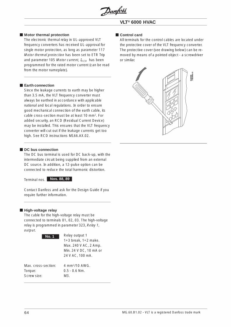
VLT® 6000 HVAC
64 MG.60.B1.02 - VLT is a registered Danfoss trade mark
DC bus connectionThe DC bus terminal is used for DC back-up, with theintermediate circuit being supplied from an externalDC source. In addition, a 12-pulse option can beconnected to reduce the total harmonic distortion.
Terminal nos.
Contact Danfoss and ask for the Design Guide if yourequire further information.
High-voltage relayThe cable for the high-voltage relay must beconnected to terminals 01, 02, 03. The high-voltagerelay is programmed in parameter 323, Relay 1,output.
Relay output 11+3 break, 1+2 make.Max. 240 V AC, 2 Amp.Min. 24 V DC, 10 mA or24 V AC, 100 mA.
Max. cross-section: 4 mm2/10 AWG.Torque: 0.5 - 0.6 Nm.Screw size: M3.
No. 1
Nos. 88, 89
Motor thermal protectionThe electronic thermal relay in UL-approved VLTfrequency converters has received UL-approval forsingle motor protection, as long as parameter 117Motor thermal protection has been set to ETR Tripand parameter 105 Motor current, IVLT,N has beenprogrammed for the rated motor current (can be readfrom the motor nameplate).
Earth connectionSince the leakage currents to earth may be higherthan 3.5 mA, the VLT frequency converter mustalways be earthed in accordance with applicablenational and local regulations. In order to ensuregood mechanical connection of the earth cable, itscable cross-section must be at least 10 mm2. Foradded security, an RCD (Residual Current Device)may be installed. This ensures that the VLT frequencyconverter will cut out if the leakage currents get toohigh. See RCD instructions MI.66.AX.02.
Control cardAll terminals for the control cables are located underthe protective cover of the VLT frequency converter.The protective cover (see drawing below) can be re-moved by means of a pointed object - a screwdriveror similar.

VLT® 6000 HVAC
65MG.60.B1.02 - VLT is a registered Danfoss trade mark
Inst
alla
tio
n
Electrical installation, control cables
Torque: 0.5 - 0.6 Nm.Screw size: M3.
Generally speaking, control cables must be screened/armoured and the screen must be connected bymeans of a cable clamp at both ends to the metalcabinet of the unit (see instructions for installationpage 57).Normally, the screen must also be connected to thebody of the controlling unit (follow the instructions forinstallation given for the unit in question).If very long control cables are used, 50/60 Hz earthloops may occur that will disturb the whole system.This problem can be solved by connecting one end ofthe screen to earth via a 100nF condenser (keepingleads short).

VLT® 6000 HVAC
66 MG.60.B1.02 - VLT is a registered Danfoss trade mark
Connection example, VLT 6000 HVACThe diagram below gives an example of a typical VLT6000 HVAC installation.The mains supply is connected to terminals 91 (L1),92 (L2) and 93 (L3), while the motor is connected to96 (U), 97 (V) and 98 (W). These numbers can also beseen from the terminals of the VLT frequencyconverter.An external DC supply or a 12-pulse option can beconnected to terminals 88 and 89. Please ask Danfossfor a Design Guide to learn more.Analogue inputs can be connected to terminals 53 [V],54 [V] and 60 [mA]. These inputs can be programmedfor either reference, feedback or thermistor. SeeAnalogue inputs in parameter group 300.
There are 8 digital inputs, which can be connected toterminals 16-19, 27, 29, 32, 33. These inputs can beprogrammed in accordance with the table on page69.There are two analogue/digital outputs (terminals 42and 45), which can be programmed to show thepresent status or a process value, such as 0-fMAX.Relay outputs 1 and 2 can be used for giving thepresent status or a warning.On terminals 68 (P+) and 69 (N-) RS 485 interface,the VLT frequency converter can be controlled andmonitored via serial communication.
* These terminals can be programmed for other functions.

VLT® 6000 HVAC
67MG.60.B1.02 - VLT is a registered Danfoss trade mark
Inst
alla
tio
n
Switches 1-4The dipswitch is located on the control card.It is used for serial communication and external DCsupply.The switching position shown is the factory setting.
Switch 1 has no function.Switches 2 and 3 are used for terminating an RS 485interface, serial communication. In the first and thelast VLT frequency converter, switches 2 and 3 mustbe ON. In the other VLT frequency converters,switches 2 and 3 must be OFF.Switch 4 is used if an external 24 V DC supply isrequired for the control terminals.Switch 4 separates the common potential for theinternal 24 V DC supply from the common potential ofthe external 24 V DC supply.
NB!Please note that when Switch 4 is in position"OFF", the external 24 V DC supply is
galvanically isolated from the VLT frequency converter.
Electrical installation, control cablesTorque: 0.5-0.6 NmScrew size: M3See page 56 for correct termination of control cables.
No. FunctionRelay output 1 can be used forindicating status and warnings.
Voltage supply to digital inputs. For the24 V DC to be used for digital inputs,switch 4 on the control card must beclosed, position "on".
Digital inputs. See parameters 300-307Digital inputs.
Common for digital inputs.
Common for analogue/digital outputs.Must be connnected to terminal 55 bymeans of a three-wire transmitter. SeeExamples of connection.
Analogue/digital outputs for indicatingfrequency, reference, current and torque.See parameters 319-322 Analogue/digital outputs.
Supply voltage to potentiometer andthermistor 10 V DC.
Analogue voltage input, 0 - 10 V DC.
Common for analogue voltage inputs.
61
68, 69
No. FunctionAnalogue current input 0/4-20 mA.See parameters 314-316 Terminal 60.
Termination of serial communication.See page 56.This terminal is not normally to be used.
RS 485 interface, serial communication.Where the VLT frequency converter isconnected to a bus, switches 2 and 3(switches 1- 4 - see next page) must beclosed on the first and the last VLTfrequency converter. On the remainingVLT frequency converters, switches 2and 3 must be open. The factory settingis closed (position on).
12, 13
16-33
20
39
42, 45
50
53, 54
55
04, 05
60

VLT® 6000 HVAC
68 MG.60.B1.02 - VLT is a registered Danfoss trade mark
Connection examplesSingle-pole start/stop
- Start/stop using terminal 18.Parameter 302 = Start [1]
- Quick-stop using terminal 27.Parameter 304 = Coasting stop, inverse [0]
Digital speed up/down
- Speed up and down using terminals 32 and 33.Parameter 306 = Speed up [7]Parameter 307 = Speed down [7]Parameter 305 = Freeze reference [2]
Potentiometer reference
- Parameter 308 = Reference [1]Parameter 309 = Terminal 53, min. scalingParameter 310 = Terminal 53, max. scaling
- Start permitted with terminal 16.Parameter 300 = Start enabled [8].
- Start/stop with terminal 18.Parameter 302 = Start [1].
- Quickstop with terminal 27.Parameter 304 = Coasting stop, inverse [0].
- Activated damper (motor)Parameter 323 = Start command active [13].
Run permissive
2-zone regulation
- Parameter 308 = Feedback [2].- Parameter 311 = Feedback [2].
Transmitter connection
- Parameter 314 = Reference [1]- Parameter 315 = Terminal 60, min. scaling- Parameter 316 = Terminal 60, max. scaling

VLT® 6000 HVAC
69MG.60.B1.02 - VLT is a registered Danfoss trade mark
Pro
gra
mm
ing
Control unit LCPThe front of the VLT frequency converter features acontrol panel - LCP (Local Control Panel). This is acomplete interface for operation and programming ofthe VLT 6000 HVAC.The control panel is detachable and can - as analternative - be installed up to 3 metres away from theVLT frequency converter, e.g. on the front panel, bymeans of a mounting kit option.The functions of the control panel can be divided intofive groups:1. Display2. Keys for changing display mode3. Keys for changing program parameters4. Indicator lamps5. Keys for local operation.All data are indicated by means of a 4-line alpha-numeric display, which, in normal operation, is able toshow 4 operating data values and 3 operatingcondition values continuously. During programming,all the information required for quick, effectiveparameter Setup of the VLT frequency converter willbe displayed. As a supplement to the display, thereare three indicator lamps for voltage (ON), warning(WARNING) and alarm (ALARM), respectively.All VLT frequency converter parameter Setups can bechanged immediately via the control panel, unless thisfunction has been programmed to be Locked [1] viaparameter 016 Lock for data change or via a digitalinput, parameters 300-307 Lock for data change.
Control keys for parameter SetupThe control keys are divided into functions. Thismeans that the keys between display and indicatorlamps are used for parameter Setup, includingselecting the display indication during normaloperation.
[DISPLAY / STATUS] is used for selectingthe indication mode of the display or whenreturning to the Display mode from eitherthe Quick menu or the Extend menumode.
[QUICK MENU] gives access to theparameters used for the Quick menu. It ispossible to switch between the Quickmenu and the Extend menu modes.
[EXTEND MENU] gives access to allparameters. It is possible to switchbetween the Extend menu and the Quickmenu modes.
[CHANGE DATA] is used for changing asetting selected either in the Extend menuor the Quick menu mode.
[CANCEL] is used if a change of the selec-ted parameter is not to be carried out.
[OK] is used for confirming a change of theparameter selected.

VLT® 6000 HVAC
70 MG.60.B1.02 - VLT is a registered Danfoss trade mark
[+/-] is used for selecting parameters andfor changing a chosen parameter. Thesekeys are also used to change the localreference.In addition, the keys are used in Displaymode to switch between operation variablereadouts.
[<>] is used when selecting a parametergroup and for moving the cursor whenchanging numerical values.
Indicator lampsAt the bottom of the control panel is a red alarm lampand a yellow warning lamp, as well as a green voltageLED.
red yellow green
If certain threshold values are exceeded, the alarmand/or warning lamp is activated, and a status oralarm text is displayed.
NB!The voltage indicator lamp is activated whenthe VLT frequency converter receives voltage.
Local controlUnderneath the indicator lamps are keys for localcontrol.
[HAND START] is used if the VLT frequencyconverter is to be controlled via the controlunit. The VLT frequency converter will startthe motor, since a start command is givenby means of [HAND START].On the control terminals, the followingcontrol signals will still be active when[HAND START] is activated:• Hand start - Off stop - Auto start• Safety Interlock• Reset• Coasting stop inverse• Reversing• Setup select lsb - Setup select msb• Jog• Run permissive• Lock for data change• Stop command from serial
communication
NB!If parameter 201 Output frequency low limit fMIN
is set to an output frequency greater than 0Hz, the motor will start and ramp up to this frequencywhen [HAND START] is activated.
[OFF/STOP] is used for stopping the con-nected motor. Can be selected as Enable[1] or Disable [0] via parameter 013. If thestop function is activated, line 2 will flash.
[AUTO START] is used if the VLT frequencyconverter is to be controlled via the controlterminals and/or serial communication.When a start signal is active on the controlterminals and/or the bus, the VLTfrequency converter will start.
NB!An active HAND-OFF-AUTO signal via thedigital inputs will have higher priority than the
control keys [HAND START]-[AUTO START].
[RESET] is used for resetting the VLTfrequency converter after an alarm (trip).Can be selected as Enable [1] or Disable [0]via parameter 015 Reset on LCP.
Display modeIn normal operation, any 4 different operating variablescan be indicated continuously: 1.1 and 1.2 and 1.3and 2. The present operating status or alarms andwarnings that have arisen are shown in line 2 in theform of a number. In the case of alarms, the alarm inquestion will be shown in lines 3 and 4, accompaniedby an explanatory note. Warnings will flash in line 2,with an explanatory note in line 1. In addition, thedisplay shows the active Setup.The arrow indicates the direction of rotation; here theVLT frequency converter has an active reversingsignal. The arrow body disappears if a stop commandis given or if the output frequency falls below 0.01 Hz.The bottom line gives the status of the VLT frequencyconverter. See next page.The scroll list on the next page gives the operatingdata that can be shown for variable 2 in display mode.Changes are made via the [+/-] keys.
VAR 2 SETUP
1
STATUS
VAR 1.1 VAR 1.2 VAR 1.3

VLT® 6000 HVAC
71MG.60.B1.02 - VLT is a registered Danfoss trade mark
Pro
gra
mm
ing
Display mode, cont.The table below gives the operating data options forthe first and second line of the display.Scroll-list: Unit:Resulting reference, % [%]Resulting reference, unit [unit]Frequency [Hz]% of maximum output frequency [%]Motor current [A]Power [kW]Power [HP]Output energy [kWh]Hours run [hours]Used-defined readout [unit]Setpoint 1 [unit]Setpoint 2 [unit]Feedback 1 [unit]Feedback 2 [unit]Feedback [unit]Motor voltage [V]DC-link voltage [V]Thermal load on motor [%]Thermal load on VLT [%]Input status, dig. input [binary code]Input status, analogue terminal 53 [V]Input status, analogue terminal 54 [V]Input status, analogue terminal 60 [mA]Pulse reference [Hz]External reference [%]Heat sink temperature [°C]User-defined text [-]
Three operating data values can be shown in the firstdisplay line, while one operating variable can beshown in the second display line. To be programmedvia parameters 007, 008, 009 and 010 Displayreadout.
• Status line:
The left part of the status line indicates the controlelement of the VLT frequency converter that is active.AUTO means that control is via the control terminals,while HAND indicates that control is via the local keyson the control unit.OFF means that the VLT frequency converter ignoresall control commands and stops the motor.The centre part of the status line indicates thereference element that is active. REMOTE means thatthe reference from the control terminals is active,while LOCAL indicates that the reference isdetermined via the [+/-] keys on the control panel.
The last part of the status line indicates the currentstatus, for example "Running", "Stop" or "Alarm".
Display mode II:This display mode makes it possible to have threeoperating data values displayed at the same time inline 1.The operating data values are determined inparameters 007-010 Display readout.
SETUP
1
FREQUENCY
AUTO REMOTE RUNNING
40.0Hz
50.0HzSETUP
1
100% 7,8A 5,9KW
Display mode I:VLT 6000 HVAC offers different display modes de-pending on the mode selected for the VLT frequencyconverter. The figure on the next page shows the wayto navigate between different display modes.Below is a display mode, in which the VLT frequencyconverter is in Auto mode with remote reference at anoutput frequency of 40 Hz.In this display mode, reference and control are deter-mined via the control terminals.The text in line 1 gives the operating variable shown inline 2.
Line 2 gives the current output frequency and theactive Setup.Line 4 says that the VLT frequency converter is inAuto mode with remote reference, and that the motoris running.
AUTO REMOTE RUNNING
SETUP
1
80.0% 5.08A 2.15kW
40.0Hz
HANDOFF
STOPRAMPINGJOGGING....STAND BY
LOCAL
AUTO REMOTE RUNNING

VLT® 6000 HVAC
72 MG.60.B1.02 - VLT is a registered Danfoss trade mark
Display mode II
Display mode III:This display mode can be generated as long as the[DISPLAY MODE] key is kept depressed. In the first line,operating data names and units of operating data aredisplayed. In the second line, operating data 2 remainsunchanged. When the key is released, the differentoperating data values are shown.
Display mode IV:This display mode is only generated in connection withlocal reference, see also reference handling on page 60.In this display mode, the reference is determined via the[+/-] keys and control is carried out by means of thekeys underneath the indicator lamps.The first line indicates the required reference.The third line gives the relative value of the presentoutput frequency at any given time in relation to themaximum frequency. The display is in the form of a bargraph.
Navigation between displaymodes
With remotereference
SETUP
1
USE +/- 40Hz
HAND LOCAL RUNNING
40.0Hz0 ----- 60
40.0Hz SETUP
1
80% 7,8A 5,9KW
40.0Hz SETUP
1
REF% CURR.A POW.,KW
Keep the [DISPLAYMODE] key down
Display mode I
Display mode IV
Display mode III
SETUP
1
FREQENCY
40.0Hz
With local reference
Press briefly
50.0HzSETUP
1
REF% CURR.A POW.,KW
AUTO REMOTE RUNNING
SETUP
1
USE +/- 40Hz
40Hz0 ----- 60
AUTO REMOTE RUNNING
AUTO REMOTE RUNNING
AUTO REMOTE RUNNING
AUTO REMOTE RUNNING

VLT® 6000 HVAC
73MG.60.B1.02 - VLT is a registered Danfoss trade mark
Pro
gra
mm
ing
Changing dataRegardless of whether a parameter has been selectedunder the Quick menu or the Extend menu, theprocedure for changing data is the same.Pressing the [CHANGE DATA] key gives access tochanging the selected parameter, following which theunderlining in line 4 will flash on the display.The procedure for changing data depends onwhether the selected parameter represents anumerical data value or a functional value.If the chosen parameter represents a numeric datavalue, the first digit can be changed by means of the[+/-] keys. If the second digit is to be changed, firstmove the cursor by using the [<>] keys, then changethe data value using the [+/-] keys.
The selected digit is indicated by a flashing cursor.The bottom display line gives the data value that willbe entered (saved) when signing off by pressing the[OK] button. Use [CANCEL] to cancel the change.
If the selected parameter is a functional value, theselected text value can be changed by means of the[+/-] keys.
The functional value flashes until signing off bypressing the [OK] button. The functional value hasnow been selected. Use [CANCEL] to cancel thechange.
3.90 A SETUP
1
MOTOR CURRENT
210 REFERENCE TYPE
SUM
24.2 Hz SETUP
1
FREQUENCY
205 MAX. REFERENCE
000050,000 Hz
Infinitely variable change of numeric data valueIf the chosen parameter represents a numeric datavalue, a digit is first selected by means of the [<>]keys.
Then the chosen digit is changed infinitely variably bymeans of the [+/-] keys:
The chosen digit is indicated by the digit flashing.The bottom display line shows the data value that willbe entered (saved) when signing off with [OK].
50.0 HZ SETUP
1
FREQUENCY
209 JOG FREQUENCY
50.0 HZ SETUP
1
FREQUENCY
209 JOG FREQUENCY
10.0 HZ
09.0 HZ
Changing of data value, step-by-stepCertain parameters can be changed both step by stepand infinitely variably. This applies to Motor power (pa-rameter 102), Motor voltage (parameter 103) andMotor frequency (parameter 104).This means that the parameters are changed both asa group of numeric data values and as numeric datavalues infinitely variably.
Manual initialisationDisconnect from mains and hold the [DISPLAY/STATUS] + [CHANGE DATA] + [OK] keys down whileat the same time reconnecting the mains supply.Release the keys; the VLT frequency converter hasnow been programmed for the factory setting.
The following parameters are not zeroed by means ofmanual initialisation:parameter 500, Protocol
600, Operating hours601, Hours run602, kWh counter603, Number of power-ups604, Number of overtemperatures605, Number of overvoltages
It is also possible to carry out initialisation via parame-ter 620 Operating mode, see page 145 regardingprocedure.

VLT® 6000 HVAC
74 MG.60.B1.02 - VLT is a registered Danfoss trade mark
Quick menu: Parameter 1 of 12Used to select the language for the display.
Quick menu: Parameter 2 of 12Select the kW value that equals the rated motor valuePM,N. There is a choice of four undersizes or one oversizein relation to the factory setting.
Quick menu: Parameter 3 of 12Used to set the rated motor voltage UM,N while taking intoconsideration whether the motor is star or deltaconnected.
Quick menu: Parameter 4 of 12Used to select the rated motor frequency fM,N.
Quick menu: Parameter 5 of 12Used to select motor current IM,N while taking intoconsideration whether the motor is star or deltaconnected.
Quick menu: Parameter 6 of 12Used to select the value that corresponds to the ratedmotor speed nM,N that can be seen from the nameplatedata.
Quick menu: Parameter 7 of 12Used to select a minimum frequency limit,corresponding to the lowest frequency at which themotor is to run.
Quick menu: Parameter 8 of 12Used to select a maximum frequency limit,corresponding to the highest frequency at which themotor is to run.
Quick menu: Parameter 9 of 12The ramp-up time is the acceleration time from 0 Hz tothe rated motor frequency fM,N (parameter 104).
Quick menu: Parameter 10 of 12The ramp-down time is the deceleration time from therated motor frequency fM,N (parameter 104) to 0 Hz.
Quick menu: Parameter 11 of 12Relay output 1 can be used for indicating status andwarnings. The relay is activated when the conditions forthe relevant data values have been fulfilled.
Quick menu: Parameter 12 of 12Relay output 2 can be used for indicating status andwarnings. The relay is activated when the conditions forthe relevant data values have been fulfilled.
Quick menuThe [QUICK MENU] key gives access to the 12most important parameters of the VLT frequencyconverter. After programming, the VLT frequencyconverter will in most cases be readyfor operation. Scroll through theQuick menu using the [+/-]keys and change thedata values bypushing [CHANGEDATA] + [OK].
4 of 12MOTOR
FREQUENCYpar. 104
3 of 12MOTOR VOLTAGE
par. 103
2 of 12MOTOR POWER
par. 102
1 of 12LANGUAGE
par. 001
5 of 12MOTOR
CURRENTpar. 105
6 of 12RATED MOTOR
SPEEDpar. 106
7 of 12OUTPUT FREQUENCY,
LOW LIMITpar. 201
8 of 12OUTPUT FREQUENCY,
HIGH LIMITpar. 202
9 of 12RAMP-UP TIME
par. 206
10 of 12RAMP-DOWN
TIMEpar. 207
11 of 12RELAY 1 OUTPUT
par. 323
12 of 12RELAY 2 OUPUT
par. 326
[+]
[+]
[+]
[+]
[+]
[+][+]
[+]
[+]
[+]
[+]
[+]
[-]
[-]
[-]
[-]
[-]
[-][-]
[-]
[-]
[-]
[-]
[-]
SETUP
1
USE +/- 40Hz
HAND LOCAL RUN
40Hz0 ----- 60

VLT® 6000 HVAC
75MG.60.B1.02 - VLT is a registered Danfoss trade mark
= factory setting. ( ) = display text [ ] = value for use in communication via serial communication port
Pro
gra
mm
ing
001 Language (LANGUAGE)Value:
English (ENGLISH) [0]German (DEUTSCH) [1]French (FRANCAIS) [2]Danish (DANSK) [3]Spanish (ESPAÑOL) [4]Italian (ITALIANO) [5]Swedish (SVENSKA) [6]Dutch (NEDERLANDS) [7]Portuguese (PORTUGUESA) [8]
State when delivered may vary from factory setting.
Function:
The choice in this parameter defines the language tobe used on the display.
Description of choice:
There is a choice of the languages indicated.
The Setup configurationVLT 6000 HVAC has four Setups (parameter Setups)that can be programmed independently of each other.The active Setup can be selected in parameter 002Active Setup. The active Setup number will be shownin the display under "Setup".It is also possible to set the VLT frequency converterto Multi-Setup to allow switching of Setups with thedigital inputs or serial communication.Setup shifts can be used in systems where, e.g., oneSetup is used during the day and another at night.
Parameter 003 Copying of Setups enables copyingfrom one Setup to another.By means of parameter 004 LCP copy, all Setups canbe transferred from one VLT frequency converter toanother by moving the control panel. First allparameter values are copied to the control panel. Thiscan then be moved to another VLT frequencyconverter, where all parameter values can be copiedfrom the control unit to the VLT frequency converter.
002 Active Setup (ACTIVE SETUP)Value:
Factory Setup (FACTORY SETUP) [0] Setup 1 (SETUP 1) [1]
Setup 2 (SETUP 2) [2]Setup 3 (SETUP 3) [3]Setup 4 (SETUP 4) [4]MultiSetup (MULTI SETUP) [5]
Function:
The choice in this parameter defines the Setupnumber you want to control the functions of the VLTfrequency converter.All parameters can be programmed in four individualparameter Setups, Setup 1 - Setup 4.In addition, a pre-programmed Setup called theFactory Setup exists. This only allows specificparameters to be changed.
Description of choice:
Factory Setup [0] contains the parameter values pre-set at the factory. Can be used as a data source if theother Setups are to be returned to a known state. Inthis case Factory Setup is selected as the activeSetup.Setups 1-4 [1]-[4] are four individual Setups that canbe selected as required.MultiSetup [5] is used if remote switching betweendifferent Setups is required. Terminals 16/17/29/32/33 and the serial communication port can be used forswitching between Setups.
ProgrammingUsing the [EXTEND MENU] key, it is pos-sible to have access to all the parametersfor the VLT frequency converter.
Operation and Display 000-017This parameter group makes it possible to set up thecontrol unit, e.g. with respect to language, displayreadout and the possibility of making the functionkeys on the control unit inactive.

VLT® 6000 HVAC
76
= factory setting. ( ) = display text [ ] = value for use in communication via serial communication port
MG.60.B1.02 - VLT is a registered Danfoss trade mark
004 LCP copy (LCP COPY)Value:
No copying (NO COPY) [0]Upload all parameters(UPLOAD ALL PARAMET.) [1]Download all parameters(DOWNLOAD ALL PARAM.) [2]Download power-independent par.(DOWNLOAD SIZE INDEP.) [3]
Function:
Parameter 004 LCP copy is used if the integratedcopying function of the control panel is to be used.This function is used if all parameter Setups are to becopied from one VLT frequency converter to anotherby moving the control panel.
Description of choice:
Select Upload all parameters [1] if all parameter valuesare to be transmitted to the control panel.Select Download all parameters [2] if all transmittedparameter values are to be copied to the VLTfrequency converter on which the control panel hasbeen mounted.Select Download power-independent par. [3] if onlythe power-independent parameters are to bedownloaded. This is used if downloading to a VLTfrequency converter that has a different rated powerthan the one from where the parameter Setuporiginates.
NB!Uploading/Downloading can only be carriedout in the Stop mode.
Setup of user-defined readoutParameter 005 Max. value of user-defined readoutand 006 Unit for user-defined readout allow users todesign their own readout which can be seen if user-defined readout has been selected under displayreadout. The range is set in parameter 005 Max. valueof user-defined readout and the unit is determined inparameter 006 Unit for user-defined readout. Thechoice of unit decides whether the ratio between theoutput frequency and the readout is a linear, squareor cubed ratio.
Connection examplesSetup change
- Selection of Setup using terminals 32 and 33.Parameter 306 = Selection of Setup, lsb [4]Parameter 307 = Selection of Setup, msb [4]Parameter 004 = MultiSetup [5].
003 Copying of Setups (SETUP COPY)Value:
No copying (NO COPY) [0]Copy active Setup to Setup 1(COPY TO SETUP 1) [1]Copy active Setup to Setup 2(COPY TO SETUP 2) [2]Copy active Setup to Setup 3(COPY TO SETUP 3) [3]Copy active Setup to Setup 4(COPY TO SETUP 4) [4]Copy active Setup to all (COPY TO ALL) [5]
Function:
A copy is made from the active Setup selected inparameter 002 Active Setup to the Setup or Setupsselected in parameter 003 Copying of Setups.
NB!Copying is only possible in Stop mode (motorstopped on a Stop command).
Description of choice:
The copying starts when the required copyingfunction has been selected and the [OK] key has beenpressed.The display indicates when copying is in progress.

VLT® 6000 HVAC
77MG.60.B1.02 - VLT is a registered Danfoss trade mark
= factory setting. ( ) = display text [ ] = value for use in communication via serial communication port
Pro
gra
mm
ing
005 Max. value of user-defined readout(CUSTOM READOUT )
Value:
0.01 - 999,999.99 100.00
Function:
This parameter allows a choice of the max. value ofthe user-defined readout. The value is calculated onthe basis of the present motor frequency and the unitselected in parameter 006 Unit for user-definedreadout. The programmed value is reached when theoutput frequency in parameter 202 Output frequencyhigh limit, fMAX is reached. The unit also decideswhether the ratio between output frequency andreadout is linear, square or cubed.
Description of choice:
Set the required value for max. output frequency.
006 Unit for user-defined readout(CUST. READ. UNIT)
Value:
No unit 1 [0] GPM 1 [21]% 1 [1] gal/s 1 [22]rpm 1 [2] gal/min 1 [23]ppm 1 [3] gal/h 1 [24]pulse/s 1 [4] lb/s 1 [25]l/s 1 [5] lb/min 1 [26]l/min 1 [6] lb/h 1 [27]l/h 1 [7] CFM 1 [28]kg/s 1 [8] ft3/s 1 [29]kg/min 1 [9] ft3/min 1 [30]kg/h 1 [10] ft3/h 1 [31]m3/s 1 [11] ft3/min 1 [32]m3/min 1 [12] ft/s 1 [33]m3/h 1 [13] in wg 2 [34]m/s 1 [14] ft wg 2 [35]mbar 2 [15] PSI 2 [36]bar 2 [16] lb/in2 [37]Pa 2 [17] HP 3 [38]kPa 2 [18]MWG 2 [19]kW 3 [20]
Flow and speed units are marked with 1. Pressureunits with 2, and power units with 3. See figure innext column.
Function:
Select a unit to be shown in the display in connectionwith parameter 005 Max. value of user-definedreadout.If units such as flow or speed units are selected, theratio between readout and output frequency will be alinear one.If pressure units are selected (bar, Pa, MWG, PSI,etc.), the ratio will be square.If power units (kW, HP) are selected, the ratio will becubed.The value and the unit are shown in display modewhenever User-defined readout [10] has beenselected in one of parameters 007-010 Displayreadout.
Description of choice:
Select the required unit for User-defined readout.
007 Large display readout (LARGE READOUT)Value:
Resulting reference [%] (REFERENCE [%]) [1]Resulting reference [unit] (REFERENCE [UNIT]) [2]
Frequency [Hz] (FREQUENCY [HZ]) [3]% of maximum output frequency [%](FREQUENCY [%]) [4]Motor current [A] (MOTOR CURRENT [A]) [5]Power [kW] (POWER [KW]) [6]Power [HP] (POWER [HP]) [7]Output energy [kWh] (ENERGI [UNIT]) [8]Hours run [Hours] (HOURS RUN [h]) [9]User-defined readout [-](CUSTOM READ.[UNITS])) [10]

VLT® 6000 HVAC
78
= factory setting. ( ) = display text [ ] = value for use in communication via serial communication port
MG.60.B1.02 - VLT is a registered Danfoss trade mark
Power [HP]Power [HP]Power [HP]Power [HP]Power [HP] states the actual power consumed bythe motor in HP.Output energy [kWh]Output energy [kWh]Output energy [kWh]Output energy [kWh]Output energy [kWh] states the energy consumed bythe motor since the latest reset was made inparameter 618 Reset of kWh counter.Hours run [Hours]Hours run [Hours]Hours run [Hours]Hours run [Hours]Hours run [Hours] states the number of hours thatthe motor has run since the latest reset in parameter619 Reset of hours-run counter.UserUserUserUserUser-defined readout [-]-defined readout [-]-defined readout [-]-defined readout [-]-defined readout [-] is a user-defined value,calculated on the basis of the present outputfrequency and unit, as well as the scaling in parameter005 Max. value of user-defined readout. Select unit inparameter 006 Unit for user-defined readout.Setpoint 1 [unit]Setpoint 1 [unit]Setpoint 1 [unit]Setpoint 1 [unit]Setpoint 1 [unit] is the programmed setpoint value inparameter 418 Setpoint 1. The unit is decided inparameter 415 Process units. See also Feedbackhandling on page 115.Setpoint 2 [unitSetpoint 2 [unitSetpoint 2 [unitSetpoint 2 [unitSetpoint 2 [unit] is the programmed setpoint value inparameter 419 Setpoint 2. The unit is decided inparameter 415 Process units.Feedback 1 [unit]Feedback 1 [unit]Feedback 1 [unit]Feedback 1 [unit]Feedback 1 [unit] gives the signal value of theresulting feedback 1 (Term. 53). The unit is decided inparameter 415 Process units. See also Feedbackhandling on page 115.Feedback 2 [unit]Feedback 2 [unit]Feedback 2 [unit]Feedback 2 [unit]Feedback 2 [unit] gives the signal value of theresulting feedback 2 (Term. 53). The unit is decided inparameter 415 Process units.Feedback [unit]Feedback [unit]Feedback [unit]Feedback [unit]Feedback [unit] gives the resulting signal value usingthe unit/scaling selected in parameter 413 Minimumfeedback, FBMIN, 414 Maximum feedback, FBMAX and415 Process units.Motor voltage [V]Motor voltage [V]Motor voltage [V]Motor voltage [V]Motor voltage [V] states the voltage supplied to themotor.DC link voltage [V]DC link voltage [V]DC link voltage [V]DC link voltage [V]DC link voltage [V] states the intermediate circuitvoltage in the VLT frequency converter.Thermal load, motor [%]Thermal load, motor [%]Thermal load, motor [%]Thermal load, motor [%]Thermal load, motor [%] states the calculated/estimated thermal load on the motor. 100% is thecut-out limit. See also parameter 117 Motor thermalprotection.Thermal load, VLThermal load, VLThermal load, VLThermal load, VLThermal load, VLT [%]T [%]T [%]T [%]T [%] states the calculated/estimated thermal load on the VLT frequencyconverter. 100% is the cut-out limit.Digital input [BinarDigital input [BinarDigital input [BinarDigital input [BinarDigital input [Binary code]y code]y code]y code]y code] states the signal statusfrom the 8 digital inputs (16, 17, 18, 19, 27, 29, 32and 33). Terminal 16 corresponds to the bit at the farleft. ‘0’ = no signal, ‘1’ = connected signal.Analogue input 53 [V] Analogue input 53 [V] Analogue input 53 [V] Analogue input 53 [V] Analogue input 53 [V] states the voltage value onterminal 53.
Setpoint 1 [unit] (SETPOINT 1 [UNITS]) [11]Setpoint 2 [unit] (SETPOINT 2 [UNITS]) [12]Feedback 1 (FEEDBACK 1 [UNITS]) [13]Feedback 2 (FEEDBACK 2 [UNITS]) [14]Feedback [unit] (FEEDBACK [UNITS]) [15]Motor voltage [V] (MOTOR VOLTAGE [V]) [16]DC link voltage [V] (DC VOLTAGE [V]) [17]Thermal load, motor [%](THERM.MOTOR LOAD [%]) [18]Thermal load, VLT [%](THERM.DRIVE LOAD [%]) [19]Digital input [Binary code](DIGITAL INPUT [BIN]) [20]Analogue input 53 [V] (ANALOG INPUT 53 [V]) [21]Analogue input 54 [V] (ANALOG INPUT 54 [V]) [22]Analogue input 60 [mA](ANALOG INPUT 53 [mA]) [23]Pulse reference [Hz] (PULSE REFERENCE [HZ]) [24]External reference [%] (EXT. REFERENCE [%]) [25]Heat sink temp. [°C] (HEATSINK TEMP [°C]) [26]LCP Display text (FREE PROG.ARRAY) [27]
Function:
This parameter allows a choice of the data value to beshown in the display, line 2, when the VLT frequencyconverter is turned on. The data values will also beincluded in the display mode scroll-list.Parameters 008-010 Small display readout allow achoice of another three data values, shown in line 1.See the description of the control unit on page 69.
Description of choice:
No readoutNo readoutNo readoutNo readoutNo readout can only be selected in parameters 008-010 Small display readout.Resulting reference [%]Resulting reference [%]Resulting reference [%]Resulting reference [%]Resulting reference [%] gives a percentage for theresulting reference in the range from Minimumreference, RefMIN to Maximum reference, RefMAX. Seealso reference handling, page 89.Reference [unitReference [unitReference [unitReference [unitReference [unit] gives the resulting reference in Hz inOpen loop. In Closed loop, the reference unit isselected in parameter 415 Process units.Frequency [Hz]Frequency [Hz]Frequency [Hz]Frequency [Hz]Frequency [Hz] gives the output frequency from theVLT frequency converter.% of maximum output frequency [%]% of maximum output frequency [%]% of maximum output frequency [%]% of maximum output frequency [%]% of maximum output frequency [%] is the presentoutput frequency as a percentage value of parameter202 Output frequency high limit, fMAX.Motor current [A]Motor current [A]Motor current [A]Motor current [A]Motor current [A] states the phase current of themotor measured as effective value.Power [kW]Power [kW]Power [kW]Power [kW]Power [kW] states the actual power consumed bythe motor in kW.

VLT® 6000 HVAC
79MG.60.B1.02 - VLT is a registered Danfoss trade mark
= factory setting. ( ) = display text [ ] = value for use in communication via serial communication port
Pro
gra
mm
ing
Analogue input 54 [V] Analogue input 54 [V] Analogue input 54 [V] Analogue input 54 [V] Analogue input 54 [V] states the voltage value onterminal 54.Analogue input 60 [mA]Analogue input 60 [mA]Analogue input 60 [mA]Analogue input 60 [mA]Analogue input 60 [mA] states the voltage value onterminal 60.Pulse reference [Hz]Pulse reference [Hz]Pulse reference [Hz]Pulse reference [Hz]Pulse reference [Hz] states a pulse frequency in Hzconnected to terminal 17 or terminal 29.External reference [%]External reference [%]External reference [%]External reference [%]External reference [%] gives the sum of the externalreferences as a percentage (the sum of analogue/pulse/serial communication) in the range fromMinimum reference, RefMIN to Maximum reference,RefMAX.Heat sink temp. [°C]Heat sink temp. [°C]Heat sink temp. [°C]Heat sink temp. [°C]Heat sink temp. [°C] states the present heat sinktemperature of the VLT frequency converter. The cut-out limit is 90 ± 5°C; cutting back in occurs at 60 ±5°C.LCD display textLCD display textLCD display textLCD display textLCD display text shows the text programmed inparameter 533 Display text 1 and 534 Display text 2via the serial communication port.
008 Small display readout 1.1(SMALL READOUT 1)
Value:
See parameter 007 Large display readout Reference [Unit] [2]
Function:
This parameter enables a choice of the first of threedata values to be shown on the display, line 1,position 1.This is a useful function, i.a. when setting the PIDregulator, in order to see how the process reacts to achange of reference.For display read-outs, press the [DISPLAY/STATUS]button. Data option LCP display text [27] cannot beselected with small display readout.
Description of choice:
There is a choice of 26 different data values, seeparameter 007 Large display readout.
009 Small display readout 1.2(SMALL READOUT 2)
Value:
See parameter 007 Large display readout Motorcurrent [A] [5]
Function:
See the functional description for parameter 008Small display readout.
Description of choice:
There is a choice of 26 different data values, seeparameter 007 Large display readout.
010 Small display readout 1.3(SMALL READOUT 3)
Value:
Se parameter 007 Large display readout Power [kW] [6]
Function:
See the functional description for parameter 008Small data readout.
Description of choice:
There is a choice of 26 different data values, seeparameter 007 Large display readout.
011 Unit of local reference(UNIT OF LOC REF)
Value:
Hz (HZ) [0]% of output frequency range (%) (% OF FMAX) [1]
Function:
This parameter decides the local reference unit.
Description of choice:
Choose the required unit for local reference.
012 Hand start on LCP(HAND START BTTN)
Value:
Disable (DISABLE) [0] Enable (ENABLE) [1]
Function:
This parameter allows selection/deselection of theHand start key on the control panel.
Description of choice:
If Disable [0] is selected in this parameter, the [HANDSTART] key will be inactive.

VLT® 6000 HVAC
80
= factory setting. ( ) = display text [ ] = value for use in communication via serial communication port
MG.60.B1.02 - VLT is a registered Danfoss trade mark
013 OFF/STOP on LCP (STOP BUTTON)Value:
Disable (DISABLE) [0] Enable (ENABLE) [1]
Function:
This parameter allows selection/deselection of thelocal stop key on the control panel.
Description of choice:
If Disable [0] is selected in this parameter, the [OFF/STOP] key will be inactive.
NB!If Disable is selected, the motor cannot bestopped by means of the [OFF/STOP] key.
014 Auto start on LCP (AUTO START BTTN)Value
Disable (DISABLE) [0] Enable (ENABLE) [1]
Function:
This parameter allows selection/deselection of theauto start key on the control panel.
Description of choice:
If Disable [0] is selected in this parameter, the [AUTOSTART] key will be inactive.
015 Reset on LCP (RESET BUTTON)Value:
Disable (DISABLE) [0] Enable (ENABLE) [1]
Function:
This parameter allows selection/deselection of thereset key on the control panel.
Description of choice:
If Disable [0] is selected in this parameter, the [RESET]key will be inactive.
NB!Only select Disable [0] if an external resetsignal has been connected via the digital
inputs.
016 Lock for data change(DATA CHANGE LOCK)
Value:
Not locked (NOT LOCKED) [0]Locked (LOCKED) [1]
Function:
This parameter allows the control panel to be ‘locked’,which means that it is not possible to carry out datamodifications via the control unit.
Description of choice:
If Locked [1] is selected, data modifications in theparameters cannot be made, although it will still bepossible to carry out data modifications via the bus.Parameters 007-010 Display readout can be changedvia the control panel.It is also possible to lock for data modifications inthese parameters by means of a digital input, seeparameters 300-307 Digital inputs on page 97.
017 Operating state at power up, localcontrol (POWER UP ACTION)
Value:
Auto restart (AUTO RESTART) [0]OFF/Stop (OFF/STOP) [1]
Function:
Setting of the desired operating mode when themains voltage is reconnected.
Description of choice:
Auto restart [0] is selected if the VLT frequency con-verter is to start up in the same start/stop conditionas immediately before power to the converter is cut off.OFF/Stop [1] is selected if the VLT frequency con-verter is to remain stopped when the mains voltage isconnected, until a start command is active. To restart,activate the key [HAND START] or [AUTO START] byusing the control panel.
NB!:If [HAND START] or [AUTO START] cannot beactivated by the keys on the control panel (see
parameter 012/014 Hand/Auto start on LCP) themotor will not be able to restart if OFF/Stop [1] isselected.If Handstart or Autostart has been programmed foractivation via the digital inputs, the motor will not beable to restart if OFF/Stop [1] is selected.

VLT® 6000 HVAC
81MG.60.B1.02 - VLT is a registered Danfoss trade mark
= factory setting. ( ) = display text [ ] = value for use in communication via serial communication port
Pro
gra
mm
ing
Load and Motor 100-117This parameter group allows the con-figuration of regulation parameters andthe choice of torque characteristics towhich the VLT frequency converter is tobe adapted.The motor nameplate data must be set
and automatic motor adaptation can be carried out. Inaddition, DC brake parameters can be set and themotor thermal protection can be activated.
ConfigurationThe selection of configuration and torque characteris-tics influences the parameters that can be seen in thedisplay. If Open loop [0] is selected, all parametersrelating to PID regulation will be hidden.Consequently, the user is only able to see the para-meters that are of significance for a given application.
100 Configuration (CONFIG. MODE)Value:
Open loop (OPEN LOOP) [0]Closed loop (CLOSED LOOP) [1]
Function:
This parameter is used for selecting the configurationto which the VLT frequency converter is to beadapted.
Description of choice:
If Open loop [0] is selected, normal speed control isobtained (without feedback signal), i.e. if the referenceis changed, the motor speed will change.If Closed loop [1] is selected, the internal processregulator is activated to enable accurate regulation inrelation to a given process signal.The reference (setpoint) and the process signal (feed-back) can be set to a process unit as programmed inparameter 415 Process units.See Feedback handling on page 115.
101 Torque characteristics( VT CHARACT)
Value:
Automatic Energy Optimisation(AEO FUNCTION) [0]Parallel motors (MULTIPLE MOTORS) [1]
Function:
This parameter allows a choice of whether the VLTfrequency converter has one or several motorsconnected to it.
Description of choice:
If Automatic Energy Optimisation [0] has beenselected, only one motor may be connected to theVLT frequency converter. The AEO function ensuresthat the motor obtains its maximum efficiency andminimises motor interference.Select Parallel motors [1] if more than one motor isconnected to the output in parallel. See thedescription under parameter 108 Start voltage ofparallel motors regarding the setting of parallel motorstart voltages.

VLT® 6000 HVAC
82
= factory setting. ( ) = display text [ ] = value for use in communication via serial communication port
MG.60.B1.02 - VLT is a registered Danfoss trade mark
NB!It is important that the values set in parameters102-106 Nameplate data correspond to the
nameplate data of the motor with respect to eitherstar coupling Y or delta coupling ∆.
102 Motor power, PM,N (MOTOR POWER)Value:
0.25 kW (0.25 KW) [25]0.37 kW (0.37 KW) [37]0.55 kW (0.55 KW) [55]0.75 kW (0.75 KW) [75]1.1 kW (1.10 KW) [110]1.5 kW (1.50 KW) [150]2.2 kW (2.20 KW) [220]3 kW (3.00 KW) [300]4 kW (4.00 KW) [400]5,5 kW (5.50 KW) [550]7,5 kW (7.50 KW) [750]11 kW (11.00 KW) [1100]15 kW (15.00 KW) [1500]18.5 kW (18.50 KW) [1850]22 kW (22.00 KW) [2200]30 kW (30.00 KW) [3000]37 kW (37.00 KW) [3700]45 kW (45.00 KW) [4500]55 kW (55.00 KW) [5500]75 kW (75.00 KW) [7500]90 kW (90.00 KW) [9000]110 kW (110.00 KW) [11000]132 kW (132.00 KW) [13200]160 kW (160.00 KW) [16000]200 kW (200.00 KW) [20000]250 kW (250.00 KW) [25000]300 kW (300.00 KW) [30000]
Depends on the unit
Function:
This is where to select the kW value PM,N thatcorresponds to the rated power of the motor.At the works, a rated kW value PM,N has been selectedthat depends on the type of unit.
Description of choice:
Select a value that equals the nameplate data on themotor. There are 4 possible undersizes or 1 oversizein comparison with the factory setting.Also, alternatively it is possible to set the value formotor power as an infinitely variable value, see theprocedure on page 73.
103 Motor voltage, UM,N
(MOTOR VOLTAGE)Value:
200 V [200]208 V [208]220 V [220]230 V [230]240 V [240]380 V [380]400 V [400]415 V [415]440 V [440]460 V [460]480 V [480]500 V [500]
Depends on the unit
Function:
This is where the rated motor voltage UM,N is set foreither star Y or delta ∆.
Description of choice:
Select a value that equals the nameplate data on themotor, regardless of the mains voltage of the VLTfrequency converter.Furthermore, alternatively it is possible to set the valueof the motor voltage infinitely variably, see also theprocedure on page 73.

VLT® 6000 HVAC
83MG.60.B1.02 - VLT is a registered Danfoss trade mark
= factory setting. ( ) = display text [ ] = value for use in communication via serial communication port
Pro
gra
mm
ing
104 Motor frequency, fM,N
(MOTOR FREQUENCY)Value:
50 Hz (50 Hz) [50]60 Hz (60 Hz) [60]
Function:
This is where the rated motor frequency fM,N isselected.
Description of choice:
Select a value that equals the nameplate data on themotor.Furthermore, it is also possible to set the value formotor frequency infinitely variably in the 24-1000 Hzrange.
105 Motor current, IM,N (MOTOR CURRENT)Value:
0.01 - IVLT,MAX A Depends on the choice of motor.
Function:
The rated motor current IM,N forms part of the VLTfrequency converter calculations i.a. of torque andmotor thermal protection. Set the motor current IVLT,N,taking into account the star Y or delta ∆ connectedmotor.
Description of choice:
Set a value that equals the nameplate data on themotor.
NB!It is important to enter the correct value, sincethis forms part of the V V CPLUS control feature.
106 Rated motor speed, nM,N
(MOTOR NOM. SPEED)Value:
100 - fM,N x 60 (max. 60000 rpm) Depends on parameter 102 Motor power, PM,N.
Function:
This is where the value is set that corresponds to therated motor speed nM,N, which can be seen from thenameplate data.
Description of choice:
Choose a value that corresponds to the motornameplate data.
NB!It is important to set the correct value, sincethis forms part of the V V CPLUS control feature.
The max. value equals fM,N x 60.fM,N is set in parameter 104 Motor frequency, fM,N.
107 Automatic motor adaptation, AMA(AUTO MOTOR ADAPT)
Value:
Optimisation disable (NO AMA) [0]Automatic adaptation (RUN AMA) [1]Automatic adaptation with LC-filter(RUN AMA WITH LC-FILT) [2]
Function:
Automatic motor adaptation is a test algorithm thatmeasures the electrical motor parameters at motorstandstill. This means that AMA itself does not supplyany torque.AMA is useful when commissioning systems, wherethe user wants to optimise the adjustment of the VLTfrequency converter to the motor applied. This featureis used in particular where the factory setting doesnot adequately cover the motor in question.
For the best adjustment of the VLT frequency conver-ter, it is recommended to carry out AMA on a coldmotor.It must be noted that repeated AMA runs may lead toa heating of the motor that will result in an increase ofthe stator resistance RS. However, this is not normallycritical.

VLT® 6000 HVAC
84
= factory setting. ( ) = display text [ ] = value for use in communication via serial communication port
MG.60.B1.02 - VLT is a registered Danfoss trade mark
It is possible via parameter 107 Automatic motoradaptation, AMA to choose whether a completeautomatic motor adaptation Automatic adaptation [1]is to be carried out, or whether reduced automaticmotor adaptation Automatic adaptation with LC-filter[2] is to be made.It is only possible to carry out the reduced test if aLC-filter has been placed between the VLT frequencyconverter and the motor. If a total setting is required,the LC-filter can be removed and, after completion ofthe AMA, it can be reinstalled. In Automaticoptimisation with LC-filter [2] there is no test of motorsymmetry and of whether all motor phases have beenconnected. The following must be noted when theAMA function is used:- For AMA to be able to determine the motor
parameters optimally, the correct nameplate datafor the motor connected to the VLT frequencyconverter must be entered in parameters 102 to106.
- The duration of a total automatic motor adaptationvaries from a few minutes to approx. 10 minutesfor small motors, depending on the rating of themotor used (the time for a 7.5 kW motor, forexample, is approx. 4 minutes).
- Alarms and warnings will be shown in the displayif faults occur during motor adaptation.
- AMA can only be carried out if the rated motorcurrent of the motor is min. 35% of the ratedoutput current of the VLT frequency converter.
- If automatic motor adaptation is to bediscontinued, press the [OFF/STOP] key.
NB!AMA is not allowed on motors connected inparallel.
Description of choice:
Select Automatic adaptation [1] if the VLT frequencyconverter is to carry out a complete automatic motoradaptation.Select Automatic adaptation with LC-filter [2] if a LC-filter has been placed between the VLT frequencyconverter and the motor.
Procedure for automatic motor adaptation:1. Set the motor parameters in accordance with the
motor nameplate data given in parameters 102-106 Nameplate data.
2. Connect 24 V DC (possibly from terminal 12) toterminal 27 on the control card.
3. Select Automatic adaptation [1] or Automaticadaptation with LC-filter [2] in parameter 107Automatic motor adaptation, AMA.
4. Start up the VLT frequency converter or connectterminal 18 (start) to 24 V DC (possibly fromterminal 12).
5. After a normal sequence, the display reads:AMA STOP. After a reset, the VLT frequencyconverter will be ready to start operation again.
If the automatic motor adaptation is to bestopped:1. Press the [OFF/STOP] key.
If there is a fault, the display reads:ALARM 221. Press the [Reset] key.2. Check for possible causes of the fault in accor-
dance with the alarm message. See page 101.
If there is a warning, the display reads:WARNING 39-421. Check for possible causes of the fault in
accordance with the warning. See page 101.2. Press the [CHANGE DATA] key and select
"Continue" if AMA is to continue despite thewarning, or press the [OFF/STOP] key to stop theautomatic motor adaptation.
108 Start voltage of parallel motors(MULTIM.START VOLT)
Value:
0.0 - parameter 103 Motor voltage, UM,N
depends on par. 103 Motor voltage, UM,N
Function:
This parameter specifies the start-up voltage of thepermanent VT characteristics at 0 Hz for motorsconnected in parallel.The start-up voltage represents a supplementaryvoltage input to the motor. By increasing the start-upvoltage, motors connected in parallel receive a higherstart-up torque. This is used especially for smallmotors (< 4.0 kW) connected in parallel, as they havea higher stator resistance than motors above 5.5 kW.This function is only active if Parallel motors [1] has beenselected in parameter 101 Torque characteristics.
Description of choice:
Set the start-up voltage at 0 Hz. The maximumvoltage depends on parameter 103 Motor voltage,UM,N.

VLT® 6000 HVAC
85MG.60.B1.02 - VLT is a registered Danfoss trade mark
= factory setting. ( ) = display text [ ] = value for use in communication via serial communication port
Pro
gra
mm
ing
109 Resonance damping(RESONANCE DAMP.)
Value:
0 - 500 % 100 %
Function:
High-frequency electric resonance problems betweenthe VLT frequency converter and the motor can beeliminated by adjusting the resonance damping.
Description of choice:
Adjust the damping percentage until the motorresonance has disappeared.
110 High break-away torque(HIGH START TORQ.)
Value:
0.0 - 0.5 sec. 0.0 sec.
Function:
In order to secure a high starting torque, themaximum torque for max. 0.5 sec. is allowed.However, the current is limited by the protection limitof the VLT frequency converter (inverter).0 sec. corresponds to no high break-away torque.
Description of choice:
Set the necessary time in which a high starting torqueis desired.
111 Start delay (START DELAY)Value:
0.0 - 120.0 sec. 0.0 sec.
Function:
This parameter enables a delay of the starting timeafter the conditions for start have been fulfilled. Whenthe time has passed, the output frequency will startby ramping up to the reference.
Description of choice:
Set the desired time until acceleration is to begin.
112 Motor preheater (MOTOR PREHEAT)Value:
Disable (DISABLE) [0]Enable (ENABLE) [1]
Function:
The motor preheater ensures that no condensatedevelops in the motor at stop. This function can alsobe used to evaporate condensed water in the motor.The motor preheater is only active during stop.
Description of choice:
Select Disable [0] if this function is not required.Select Enable [1] to activate motor preheating. TheDC current is set in parameter 113 Motor preheaterDC current.
113 Motor preheater DC current(PREHEAT DC-CURR.)
Value:
0 - 100 % 50 %
The maximum value depends on the rated motorcurrent, parameter 105 Motor current, IM,N.
Function:
The motor can be preheated at stop by means of aDC current to prevent moisture from entering themotor.
Description of choice:
The motor can be preheated by means of a DCcurrent. At 0%, the function is inactive; at a valuehigher than 0%, a DC current will be supplied to themotor at stop (0 Hz). In fans that rotate because ofthe air flow when they are not in operation(windmilling), this function can also be used togenerate a holding torque.
If too high a DC current is supplied for toolong, the motor can be damaged.

VLT® 6000 HVAC
86
= factory setting. ( ) = display text [ ] = value for use in communication via serial communication port
MG.60.B1.02 - VLT is a registered Danfoss trade mark
Make sure not to supply too high a brakingcurrent for too long, since otherwise themotor will be damaged because of
mechanical overload or the heat generated in themotor.
115 DC braking time(DC BRAKE TIME)
Value:
0.0 - 60.0 sec. 10.0 sec.
Function:
This parameter is for setting the DC braking time forwhich the DC braking current (parameter 113) is tobe active.
Description of choice:
Set the desired time.
116 DC brake cut-in frequency(DC BRAKE CUT-IN)
Value:
0.0 (OFF) - par. 202 Output frequencyhigh limit, fMAX OFF
Function:
This parameter is used for setting the DC brake cut-infrequency at which DC braking is to be activated inconnection with a stop command.
Description of choice:
Set the desired frequency.
DC brakingIn DC braking, the motor receives a DC current thatbrings the shaft to a halt. Parameter 114 DC brakingcurrent, decides the DC braking current as apercentage of the rated motor current IM,N.In parameter 115 DC braking time, the DC brakingtime is selected, and in parameter 116 DC brake cut-in frequency, the frequency is selected at which DCbraking becomes active.If terminal 19 or 27 (parameter 303/304 Digital input)has been programmed to DC braking inverse andshifts from logic ‘1’ to logic ‘0’, the DC braking will beactivated.When the start signal on terminal 18 changes fromlogic ‘1’ to logic ‘0’, the DC braking will be activatedwhen the output frequency becomes lower than thebrake coupling frequency.
NB!The DC brake is not to be used if the inertia of
the motor shaft is more than 20 times the inertia ofthe motor itself.
114 DC braking current(DC BRAKE CURRENT)
Value:
0 - 50 %
The maximum value depends on the rated motorcurrent. If the DC braking current is active, the VLTfrequency converter has a switching frequency of 4 kHz.
Function:
This parameter is used for setting the DC brakingcurrent that is activated upon a stop when the DCbrake frequency set in parameter 116 DC brake cut-infrequency has been reached, or if DC brake inverse isactive via terminal 27 or via the serial communicationport. The DC braking current will be active for theduration of the DC braking time set in parameter 115DC braking time.
Description of choice:
To be set as a percentage value of the rated motorcurrent IM,N set in parameter 105 Motor current, IVLT,N.100% DC braking current corresponds to IM,N.
IVLT,MAX
IM,Nx 100 [%]

VLT® 6000 HVAC
87MG.60.B1.02 - VLT is a registered Danfoss trade mark
= factory setting. ( ) = display text [ ] = value for use in communication via serial communication port
Pro
gra
mm
ing
117 Motor thermal protection(MOT. THERM PROTEC)
Value:
No protection (NO PROTECTION) [0]Thermistor warning (THERMISTOR WARNING) [1]Thermistor trip (THERMISTOR FAULT) [2]ETR Warning 1 (ETR WARNING 1) [3]
ETR Trip 1 (ETR TRIP 1) [4]ETR Warning 2 (ETR WARNING 2) [5]ETR Trip 2 (ETR TRIP 2) [6]ETR Warning 3 (ETR WARNING 3) [7]ETR Trip 3 (ETR TRIP 3) [8]ETR Warning 4 (ETR WARNING 4) [9]ETR Trip 4 (ETR TRIP 4) [10]
Function:
The VLT frequency converter is able to monitor themotor temperature in two different ways:- Via a thermistor sensor fitted to the motor. The
thermistor is connected to one of the analogueinput terminals 53 and 54.
- Calculation of the thermal load (ETR - ElectronicThermal Relay), based on the current load and thetime. This is compared with the rated motorcurrent IM,N and the rated motor frequency fM,N.The calculations made take into account the needfor a lower load at lower speeds because of lesscooling in the motor itself.
ETR functions 1-4 do not start calculating the loaduntil there is a switch-over to the Setup in which theywere selected. This enables the use of the ETRfunction, even where two or several motors alternate.
Description of choice:
Select No protection [0] if no warning or tripping isrequired when the motor is overloaded.Select Thermistor warning [1] if a warning is desiredwhen the connected thermistor gets too hot.Select Thermistor trip [2] if cutting out (trip) is desiredwhen the connected thermistor overheats.Select ETR Warning 1-4, if a warning is to come upon the display when the motor is overloadedaccording to the calculations.The VLT frequency converter can also be program-med to give off a warning signal via one of the digitaloutputs.Select ETR Trip 1-4 if tripping is desired when the mo-tor is overloaded according to the calculations.

VLT® 6000 HVAC
88
= factory setting. ( ) = display text [ ] = value for use in communication via serial communication port
MG.60.B1.02 - VLT is a registered Danfoss trade mark
References & Limits 200 - 228In this parameter group,the frequency andreference range of theVLT frequency converterare established.
This parameter group also includes:- Setting of ramp times- Choice of four preset references- Possibility of programming four bypass
frequencies.- Setting of maximum current to motor.- Setting of warning limits for current, frequency,
reference and feedback.
200 Output frequency range(FREQUENCY RANGE)
Value:
0 - 120 Hz (0 - 120 HZ) [0]0 - 1000 Hz (0 - 1000 HZ) [1]
Function:
This is where to select the maximum outputfrequency range to be set in parameter 202 Outputfrequency high limit, fMAX.
Description of choice:
Select the required output frequency range.
201 Output frequency low limit, fMIN
(MIN. FREQUENCY)Value:
0.0 - fMAX 0.0 HZ
Function:
This is where to select the maximum outputfrequency range to be set in parameter 202 Outputfrequency high limit, fMAX.
Description of choice:
A value from 0.0 Hz to the Output frequency highlimit, fMAX frequency set in parameter 202 can beselected.
202 Output frequency high limit, fMAX
(MAX. FREQUENCY)Value:
fMIN - 120/1000 Hz(par. 200 Output frequency range) 50 Hz
Function:
In this parameter, a maximum output frequency limitcan be selected that corresponds to the highestspeed at which the motor can be.
NB!The output frequency of the VLT frequencyconverter can never assume a value higher
than 1/10 of the switching frequency (parameter 407Switching frequency).
Description of choice:
A value from fMIN to the choice made in parameter 200Output frequency range can be selected.

VLT® 6000 HVAC
89MG.60.B1.02 - VLT is a registered Danfoss trade mark
= factory setting. ( ) = display text [ ] = value for use in communication via serial communication port
Pro
gra
mm
ing
Reference handlingReference handling is shown in the block diagramunderneath.The block diagram shows how a change in aparameter can affect the resulting reference.
Parameters 203 to 205 Reference handling, minimumand maximum reference and parameter 210Reference type define the way reference handling canbe carried out. The mentioned parameters are activeboth in a closed and in an open loop.
Remote references are defined as:• External references, such as analogue inputs 53,
54 and 60, pulse reference via terminal 17/29 andreference from serial communication.
• Preset references.
The resulting reference can be shown in the displayby selecting Reference [%] in parameters 007-010Display readout and in the form of a unit by selectingRemote reference [unit].See the section on Feedback handling in connectionwith a closed loop on page 115.
The sum of the external references can be shown inthe display as a percentage of the range fromMinimum reference, RefMIN to Maximum reference,RefMAX. Select External reference, % [25] in parameters007-010 Display readout if a readout is required.
It is possible to have both preset references andexternal references at the same time. In parameter210 Reference type a choice is made of how thepreset references are to be added to the externalreferences.
Furthermore, an independent local reference exists,where the resulting reference is set by means of the[+/-] keys. If local reference has been selected, theoutput frequency range is limited by parameter 201Output frequency low limit, fMIN and parameter 202Output frequency high limit, fMAX.
NB!If the local reference is active, the VLTfrequency converter will always be in Openloop [0], regardless of the choice made in
parameter 100 Configuration.
The unit of the local reference can be set either as Hzor as a percentage of the output frequency range. Theunit is selected in parameter 011 Unit of localreference.

VLT® 6000 HVAC
90
= factory setting. ( ) = display text [ ] = value for use in communication via serial communication port
MG.60.B1.02 - VLT is a registered Danfoss trade mark
203 Reference site(REFERENCE SITE)
Value:
Hand/Auto linked reference(LINKED TO HAND/AUTO)) [0]Remote reference (REMOTE) [1]Local reference (LOCAL) [2]
Function:
This parameter decides which resulting reference is tobe active. If Hand/Auto linked reference [0] is selected,the resulting reference will depend on whether theVLT frequency converter is in Hand or Auto mode.The table shows which references are active whenHand/Auto linked reference [0], Remote reference [1]or Local reference [2] has been selected. The Handmode or Auto mode can be selected via the controlkeys or via a digital input, parameters 300-307 Digitalinputs.
Reference
handling Hand mode Auto mode
Hand/Auto [0] Local ref. active Remote ref. active
Remote [1] Remote ref. active Remote ref. active
Local [2] Local ref. active Local ref. active
Description of choice:
If Hand/Auto linked reference [0] is chosen, the motorspeed in Hand mode will be decided by the localreference, while in Auto mode it depends on remotereferences and any setpoints selected.If Remote reference [1] is selected, the motor speedwill depend on remote references, regardless ofwhether Hand mode or Auto mode has been chosen.If Local reference [2] is selected, the motor speed willonly depend on the local reference set via the controlpanel, regardless of whether Hand mode or Automode has been selected.
204 Minimum reference, RefMIN
(MIN. REFERENCE)Value:
Parameter 100 Configuration = Open loop [0].0.000 - parameter 205 RefMAX 0.000 Hz
Parameter 100 Configuration = Closed loop [1].-Par. 413 Minimum feedback- par. 205 RefMAX 0.000
Function:
The Minimum reference gives the minimum value thatcan be assumed by the sum of all references. If Closedloop has been selected in parameter 100Configuration, the minimum reference is limited byparameter 413 Minimum feedback.Minimum reference is ignored when the local referenceis active (parameter 203 Reference site).The unit for the reference can be seen from thefollowing table:
Unit
Par. 100 Configuration = Open loop Hz
Par. 100 Configuration = Closed loop Par. 415
Description of choice:
Minimum reference is set if the motor is to run at aminimum speed, regardless of whether the resultingreference is 0.
205 Maximum reference, RefMAX
(MAX. REFERENCE)Value:
Parameter 100 Configuration = Open loop [0]Parameter 204 RefMIN - 1000.000 Hz 50.000 Hz
Parameter 100 Configuration = Closed loop [1]Par. 204 RefMIN
- par. 414 Maximum feedback 50.000 Hz
Function:
The Maximum reference gives the maximum valuethat can be assumed by the sum of all references. IfClosed loop [1] has been selected in parameter 100Configuration, the maximum reference cannot be setabove parameter 414 Maximum feedback. TheMaximum reference is ignored when the localreference is active (parameter 203 Reference site).

VLT® 6000 HVAC
91MG.60.B1.02 - VLT is a registered Danfoss trade mark
= factory setting. ( ) = display text [ ] = value for use in communication via serial communication port
Pro
gra
mm
ing
Description of choice:
Program the desired ramp-down time.
208 Automatic ramp-up/down(AUTO RAMPING)
Value:
Disable (DISABLE) [0] Enable (ENABLE) [1]
Function:
This function ensures that the VLT frequencyconverter does not trip during deceleration if theramp-down time set is too short. If, duringdeceleration, the VLT frequency converter registersthat the intermediate circuit voltage is higher than themax. value (see page 101), the VLT frequencyconverter automatically extends the ramp-up andramp-down time.
NB!If the function is chosen as Enable [1], theramp time may be considerably extended in
relation to the time set in parameter 207 Ramp-downtime.
Description of choice:
Program this function as Enable [1] if the VLT fre-quency converter periodically trips during ramp-down.If a quick ramp-down time has been programmed thatmay lead to a trip under special conditions, thefunction can be set to Enable [1] to avoid trips.
209 Jog frequency (JOG FREQUENCY)Value:
Par. 201 Output frequency Low limit - par. 202Output frequency high limit 10.0 HZ
Function:
The jog frequency fJOG is the fixed output frequency atwhich the VLT frequency converter is running whenthe jog function is activated.Jog can be activated via the digital inputs.
Description of choice:
Set the desired frequency.
Function, cont.:
The reference unit can be determined on the basis ofthe following table:
Unit
Par. 100 Configuration = Open loop Hz
Par. 100 Configuration = Closed loop Par. 415
Description of choice:
Maximum reference is set if the motor speed is not toexceed the set value, regardless of whether theresulting reference is higher than Maximum reference.
206 Ramp-up time (RAMP UP TIME)Value:
1 - 3600 sec. Depends on the unit
Function:
The ramp-up time is the acceleration time from 0 Hzto the rated motor frequency fM,N (parameter 104Motor frequency, fM,N). It is assumed that the outputcurrent does not reach the current limit (set inparameter 215 Current limit ILIM).
Description of choice:
Program the desired ramp-up time.
207 Ramp-down time (RAMP DOWN TIME)Value:
1 - 3600 sec. Depends on the unit
Function:
The ramp-down time is the deceleration time from therated motor frequency fM,N (parameter 104 Motorfrequency, fM,N) to 0 Hz, provided there is noovervoltage in the inverter because of the motoracting as a generator.

VLT® 6000 HVAC
92
= factory setting. ( ) = display text [ ] = value for use in communication via serial communication port
MG.60.B1.02 - VLT is a registered Danfoss trade mark
210 Reference type(REF. FUNCTION)
Value:
Sum (SUM) [0]Relative (RELATIVE) [1]External/preset (EXTERNAL/PRESET) [2]
Function:
It is possible to define how the preset references areto be added to the other references. For this purpose,Sum or Relative is used. It is also possible - by usingthe External/preset function - to select whether a shiftbetween external references and preset references iswanted.See Reference handling on page 89.
Description of choice:
If Sum [0] is selected, one of the adjusted presetreferences (parameters 211-214 Preset reference) isadded to the other external references as apercentage of the reference range (RefMIN-RefMAX).If Relative [1] is selected, one of the adjusted presetreferences (parameters 211-214 Preset reference) istotaled as a percentage of the sum of the presentexternal references.If External/preset [2] is selected, it is possible to shiftbetween external references and preset references viaterminal 16, 17, 29, 32 or 33 (parameter 300, 301,305, 306 or 307 Digital inputs). Preset references willbe a percentage value of the reference range.External reference is the sum of the analoguereferences, pulse references and any references fromserial communication.
NB!If Sum or Relative is selected, one of the presetreferences will always be active. If the preset
references are to be without influence, they should beset to 0% (as in the factory setting) via the serialcommunication port.
Reference typeThe example shows how the resulting reference iscalculated when Preset references are used togetherwith Sum and Relative in parameter 210 Referencetype. A formula for calculating the resulting referenceis given on page 156.See also the drawing on page 89.
The following parameters have been set:Par. 204 Minimum reference: 10 HzPar. 205 Maximum reference: 50 HzPar. 211 Preset reference: 15%Par. 308 Terminal 53, analogue input: Reference [1]Par. 309 Terminal 53, min. scaling: 0 VPar. 310 Terminal 53, max. scaling: 10 V
When parameter 210 Reference type is set to Sum[0], one of the adjusted Preset references (par. 211-214) will be added to the external references as apercentage of the reference range. If terminal 53 isenergized by an analogue input voltage of 4 V, theresulting reference will be as follows:
Par. 210 Reference type = Sum [0]Par. 204 Minimum reference = 10.0 HzReference contribution at 4 V = 16.0 HzPar. 211 Preset reference = 6.0 HzResulting reference = 32.0 Hz
If parameter 210 Reference type is set to Relative [1],one of the adjusted Preset references (par. 211-214)will be totaled as a percentage of the sum of thepresent external references. If terminal 53 is energizedby an analogue input voltage of 4 V, the resultingreference will be as follows:
Par. 210 Reference type = Relative [1]Par. 204 Minimum reference = 10.0 HzReference contribution at 4 V = 16.0 HzPar. 211 Preset reference = 2.4 HzResulting reference = 28.4 Hz
The graph in the next column shows the resultingreference in relation to the external reference variedfrom 0-10 V.Parameter 210 Reference type has been programmedfor Sum [0] and Relative [1], respectively. In addition, agraph is shown in which parameter 211 Presetreference 1 is programmed for 0%.

VLT® 6000 HVAC
93MG.60.B1.02 - VLT is a registered Danfoss trade mark
= factory setting. ( ) = display text [ ] = value for use in communication via serial communication port
Pro
gra
mm
ing
211 Preset reference 1 (PRESET REF. 1)212 Preset reference 2 (PRESET REF. 2)213 Preset reference 3 (PRESET REF. 3)214 Preset reference 4 (PRESET REF. 4)Value:
-100.00 % - +100.00 % 0.00%of the reference range/external reference
Function:
Four different preset references can be programmedin parameters 211-214 Preset reference. The presetreference is stated as a percentage value of thereference range (RefMIN - RefMAX) or as a percentage ofthe other external references, depending on thechoice made in parameter 210 Reference type.The choice between the preset references can bemade by activating terminal 16, 17, 29, 32 or 33, cf.the table below.
Terminal 17/29/33 Terminal 16/29/32preset ref. msb preset ref. lsb
0 0 Preset ref. 10 1 Preset ref. 21 0 Preset ref. 31 1 Preset ref. 4
Description of choice:
Set the required preset reference(s) that is/are to bethe options.
215 Current limit, ILIM
(CURRENT LIMIT)Value:
0.1 - 1.1 x IVLT,N 1.0 x IVLT,N [A]
Function:
This is where the maximum output current ILIM is set.The factory setting corresponds to the rated outputcurrent. If the current limit is to be used as motorprotection, the rated motor current must be set. If thecurrent limit is set within the range of 1.0-1.1 x IVLT,N
(the rated output current of the VLT frequencyconverter), the VLT frequency converter can onlyhandle a load intermittently, i.e. for short periods at atime. After the load has been higher than IVLT,N, it mustbe ensured that for a period the load is lower thanIVLT,N.Please note that if the current limit is set to less thanIVLT,N, the acceleration torque will be reducedcorrespondingly.
Description of choice:
Set the required maximum output current ILIM.
216 Frequency bypass, bandwidth(FREQUENCY BYPASS B.W.)
Value:
0 (OFF) - 100 Hz Disable
Function:
Some systems call for some output frequencies to beavoided because of mechanical resonance problemsin the system.These output frequencies can be programmed inparameters 217-220 Frequency bypass.In this parameter (216 Frequency bypass, bandwidth),a definition can be given of a bandwidth around eachof these frequencies.
Description of choice:
The bypass bandwidth is equal to the programmedbandwidth frequency. This bandwidth will be centeredaround each bypass frequency.
217 Frequency bypass 1(BYPASS FREQ. 1)
218 Frequency bypass 2(BYPASS FREQ. 2)
219 Frequency bypass 3(BYPASS FREQ. 3)
220 Frequency bypass 4(BYPASS FREQ. 4)
Value:
0 - 120/1000 HZ 120.0 HzThe frequency range depends on the selectionmade in parameter 200 Output frequency range.
Function:
Some systems call for some output frequencies to beavoided because of mechanical resonance problemsin the system.
Description of choice:
Enter the frequencies to be avoided.See also parameter 216 Frequency bypass,bandwidth.

VLT® 6000 HVAC
94
= factory setting. ( ) = display text [ ] = value for use in communication via serial communication port
MG.60.B1.02 - VLT is a registered Danfoss trade mark
222 Warning: High current, IHIGH
(WARN. HIGH CURR.)Value:
Parameter 221 - IVLT,MAX IVLT,MAX
Function:
If the motor current is above the limit, IHIGH, pro-grammed in this parameter, the display shows aflashing CURRENT HIGH.The warning functions in parameters 221-228 are notactive during ramp-up after a start command, ramp-down after a stop command or while stop-ped. Thewarning functions are activated when the outputfrequency has reached the resulting reference.The signal outputs can be programmed to generate awarning signal via terminal 42 or 45 and via the relayoutputs.
Description of choice:
The upper signal limit of the motor frequency, fHIGH,must be programmed within the normal workingrange of the frequency converter. See drawing atparameter 221 Warning: Low current, ILOW.
223 Warning: Low frequency, fLOW
(WARN. LOW FREQ.)Value:
0.0 - parameter 224 0.0 Hz
Function:
If the output frequency is below the limit, fLOW,programmed in this parameter, the display will show aflashing FREQUENCY LOW.The warning functions in parameters 221-228 are notactive during ramp-up after a start command, ramp-down after a stop command or while stop-ped. Thewarning functions are activated when the outputfrequency has reached the resulting reference.The signal outputs can be programmed to generate awarning signal via terminal 42 or 45 and via the relayoutputs.
Description of choice:
The lower signal limit of the motor frequency, fLOW,must be programmed within the normal workingrange of the frequency converter. See drawing atparameter 221 Warning: Low current, ILOW.
221 Warning: Low current, ILOW
(WARN. LOW CURR.)Value:
0.0 - par. 222 Warning: High current, IHIGH 0.0A
Function:
When the motor current is below the limit, ILOW,programmed in this parameter, the display shows aflashing CURRENT LOW, provided Warning [1] hasbeen selected in parameter 409 Function in case ofno load. The VLT frequency converter will trip ifparameter 409 Function in case of no load has beenselected as Trip [0].The warning functions in parameters 221-228 are notactive during ramp-up after a start command, ramp-down after a stop command or while stop-ped. Thewarning functions are activated when the outputfrequency has reached the resulting reference.The signal outputs can be programmed to generate awarning signal via terminal 42 or 45 and via the relayoutputs.
Description of choice:
The lower signal limit ILOW must be programmed withinthe normal working range of the frequency converter.

VLT® 6000 HVAC
95MG.60.B1.02 - VLT is a registered Danfoss trade mark
= factory setting. ( ) = display text [ ] = value for use in communication via serial communication port
Pro
gra
mm
ing
224 Warning: High frequency, fHIGH
(WARN. HIGH FREQ.)Value:
Par. 200 Output frequency range = 0-120 Hz [0].parameter 223 - 120 Hz 120.0 Hz
Par. 200 Output frequency range = 0-1000 Hz [1].parameter 223 - 1000 Hz 120.0 Hz
Function:
If the output frequency is above the limit, fHIGH,programmed in this parameter, the display will show aflashing FREQUENCY HIGH.The warning functions in parameters 221-228 are notactive during ramp-up after a start command, ramp-down after a stop command or while stop-ped. Thewarning functions are activated when the outputfrequency has reached the resulting reference.The signal outputs can be programmed to generate awarning signal via terminal 42 or 45 and via the relayoutputs.
Description of choice:
The higher signal limit of the motor frequency, fHIGH,must be programmed within the normal workingrange of the frequency converter. See drawing atparameter 221 Warning: Low current, ILOW.
225 Warning: Low reference, REFLOW
(WARN. LOW REF.)Value:
-999,999.999 - REFHIGH (parameter 226) 0.0 Hz
Function:
When the remote reference lies under the limit,RefLOW, programmed in this parameter, the displayshows a flashing REFERENCE LOW.
The warning functions in parameters 221-228 are notactive during ramp-up after a start command, ramp-down after a stop command or while stop-ped. Thewarning functions are activated when the outputfrequency has reached the resulting reference.The signal outputs can be programmed to generate awarning signal via terminal 42 or 45 and via the relayoutputs.
The reference limits in parameter 226 Warning: Highreference, RefHIGH, and in parameter 227 Warning:Low reference, RefLOW, are only active when remotereference has been selected.In Open loop mode the unit for the reference is Hz,while in Closed loop mode the unit is programmed inparameter 415 Process units.
Description of choice:
The lower signal limit, RefLOW, of the reference must beprogrammed within the normal working range of thefrequency converter, provided parameter 100Configuration has been programmed for Open loop[0]. In Closed loop [1] (parameter 100), RefLOW mustbe within the reference range programmed inparameters 204 and 205.
226 Warning: High reference, REFHIGH
(WARN. HIGH REF.)Value:
REFLow (parameter 225) - 999,999.999 50.0 Hz
Function:
If the resulting reference lies under the limit, RefHIGH,programmed in this parameter, the display shows aflashing REFERENCE HIGH.The warning functions in parameters 221-228 are notactive during ramp-up after a start command, ramp-down after a stop command or while stop-ped. Thewarning functions are activated when the outputfrequency has reached the resulting reference.The signal outputs can be programmed to generate awarning signal via terminal 42 or 45 and via the relayoutputs.The reference limits in parameter 226 Warning: Highreference, RefHIGH, and in parameter 227 Warning:Low reference, RefLOW, are only active when remotereference has been selected.In Open loop the unit for the reference is Hz, while inClosed loop the unit is programmed in parameter 415Process units.

VLT® 6000 HVAC
96
= factory setting. ( ) = display text [ ] = value for use in communication via serial communication port
MG.60.B1.02 - VLT is a registered Danfoss trade mark
Description of choice:
The upper signal limit, RefHIGH,of the reference mustbe programmed within the normal working range ofthe frequency converter, provided parameter 100Configuration has been programmed for Open loop[0]. In Closed loop [1] (parameter 100), RefHIGH mustbe within the reference range programmed inparameters 204 and 205.
227 Warning: Low feedback, FBLOW
(WARN LOW FDBK)Value:
-999,999.999 - FBHIGH (parameter 228) -999.999,999
Function:
If the feedback signal is below the limit, FBLOW,
programmed in this parameter, the display will show aflashing FEEDBACK LOW.The warning functions in parameters 221-228 are notactive during ramp-up after a start command, ramp-down after a stop command or while stop-ped. Thewarning functions are activated when the outputfrequency has reached the resulting reference.The signal outputs can be programmed to generate awarning signal via terminal 42 or 45 and via the relayoutputs.In Closed loop, the unit for the feedback isprogrammed in parameter 415 Process units.
Description of choice:
Set the required value within the feedback range(parameter 413 Minimum feedback, FBMIN, and 414Maximum feedback, FBMAX).
228 Warning: High feedback, FBHIGH
(WARN. HIGH FDBK)Value:
FBLOW (parameter 227) - 999,999.999 999.999,999
Function:
If the feedback signal is above the limit, FBHIGH,programmed in this parameter, the display will show aflashing FEEDBACK HIGH.The warning functions in parameters 221-228 are notactive during ramp-up after a start command, ramp-down after a stop command or while stop-ped. Thewarning functions are activated when the outputfrequency has reached the resulting reference.The signal outputs can be programmed to generate awarning signal via terminal 42 or 45 and via the relayoutputs.In Closed loop, the unit for the feedback isprogrammed in parameter 415 Process units.
Description of choice:
Set the required value within the feedback range(parameter 413 Minimum feedback, FBMIN, and 414Maximum feedback, FBMAX).

VLT® 6000 HVAC
97MG.60.B1.02 - VLT is a registered Danfoss trade mark
= factory setting. ( ) = display text [ ] = value for use in communication via serial communication port
Pro
gra
mm
ing
Inputs and outputs 300-328In this parameter group, thefunctions that relate to the input andoutput terminals of the VLTfrequency converter are defined. The
digital inputs (terminals 16, 17, 18, 19, 27, 32 and 33)are programmed in parameters 300-307. The tablebelow gives the options for programming the inputs.The digital inputs require a signal of 0 or 24 V DC. Asignal lower than 5 V DC is a logic ‘0’, while a signalhigher than 10 V DC is a logic ‘1’.The terminals for the digital inputs can be connectedto the internal 24 V DC supply, or an external 24 V DCsupply can be connected.The drawings in the next column show one Setupusing the internal 24 V DC supply and one Setupusing an external 24 V DC supply.
Digital inputs terminal no. 16 17 18 19 27 29 32 33parameter 300 301 302 303 304 305 306 307
Value:
No function (NO OPERATION) [0] [0] [0] [0] [0] [0] [0]Reset (RESET) [1] [1] [1] [1] [1]Coasting stop, inverse (COAST INVERSE) [0]Reset and coasting stop, inverse(RESET & COAST INVERSE) [1]Start (START) [1]Reversing (REVERSE) [1]Reversing and start (START REVERSE) [2]DC-braking, inverse (DC BRAKE INVERSE) [3] [2]Safety interlock (SAFETY INTERLOCK) [3]Freeze reference (FREEZE REFERENCE) [2] [2] [2] [2] [2]Freeze output (FREEZE OUTPUT) [3] [3] [3] [3] [3]Selection of Setup, lsb (SETUP SELECT LSB) [4] [4] [4]Selection of Setup, msb (SETUP SELECT MSB) [4] [5] [4]Preset reference, on (PRESET REF. ON) [5] [5] [6] [5] [5]Preset reference, lsb (PRESET REF. LSB) [6] [7] [6]Preset reference, msb (PRESET REF. MSB) [6] [8] [6]Speed down (SPEED DOWN) [7] [9] [7]Speed up (SPEED UP) [7] [10] [7]Run permissive (RUN PERMISSIVE) [8] [8] [11] [8] [8]Jog (JOG) [9] [9] [12] [9] [9]Data change lock (PROGRAMMING LOCK) [10] [10] [13] [10] [10]Pulse reference (PULSE REFERENCE) [11] [14]Pulse feedback (PULSE FEEDBACK) [11]Hand start (HAND START) [11] [12] [15] [11] [12]Auto start (AUTOSTART) [12] [13] [16] [12] [13]
Switch 4, which is located on theDip switch control card, is used forseparating the common potentialof the internal 24 V DC supply from
the common potential of the external 24 V DC supply.See also the drawing on page 37.Please note that when Switch 4 is in the OFFposition, the external 24 V DC supply is galvanicallyisolated from the VLT frequency converter.

VLT® 6000 HVAC
98
= factory setting. ( ) = display text [ ] = value for use in communication via serial communication port
MG.60.B1.02 - VLT is a registered Danfoss trade mark
Function:
In parameters 300-307 Digital inputs it is possible tochoose between the different possible functionsrelated to the digital inputs (terminals 16-33).The functional options are given in the table on theprevious page.
Description of choice:
No function No function No function No function No function is selected if the VLT frequency converteris not to react to signals transmitted to the terminal.
Reset Reset Reset Reset Reset resets the VLT frequency converter after analarm; however, not all alarms can be reset (triplocked) cycling mains power supply. See table onpage 150. Reset will be activate on the rising edge ofthe signal.
Coasting stop, inverse Coasting stop, inverse Coasting stop, inverse Coasting stop, inverse Coasting stop, inverse is used to force the VLTfrequency converter to "release" the motorimmediately (the output transistors are "turned off") tomake it coast freely to stop. Logic ‘0’ implementscoasting to stop.
Reset and coasting stop, inverse Reset and coasting stop, inverse Reset and coasting stop, inverse Reset and coasting stop, inverse Reset and coasting stop, inverse is used foractivating coasting stop at the same time as reset.Logic ‘0’ implements coasting stop and reset.Reset will be activate on the falling edge of the signal.
DC braking, inverse DC braking, inverse DC braking, inverse DC braking, inverse DC braking, inverse is used for stopping the motorby energizing it with a DC voltage for a given time, seeparameters 114-116 DC brake.Please note that this function is only active if the valueof parameters 114 DC brake current and 115 DCbraking time is different from 0. Logic ‘0’ implementsDC braking. See DC braking on page 86.
Safety interlock Safety interlock Safety interlock Safety interlock Safety interlock has the same function as Coastingstop, inverse, but Safety interlock generates the alarmmessage ’external fault’ on the display when terminal27 is logic ‘0’. The alarm message will also be activevia digital outputs 42/45 and relay outputs 1/2, ifprogrammed for Safety interlock. The alarm can bereset using a digital input or the [OFF/STOP] key.
Start Start Start Start Start is selected if a start/stop command is required.Logic ‘1’ = start, logic ‘0’ = stop.
Reversing Reversing Reversing Reversing Reversing is used for changing the direction ofrotation of the motor shaft. Logic ‘0’ will notimplement reversing. Logic ‘1’ will implementreversing.
The reversing signal only changes the direction ofrotation; it does not activate the start function.Is not active together with Closed loop.
Reversing and start Reversing and start Reversing and start Reversing and start Reversing and start is used for start/stop andreversing using the same signal.A start signal via terminal 18 at the same time is notallowed.Is not active together with Closed loop.
DC braking DC braking DC braking DC braking DC braking is used to stop the motor by energizing itwith a DC voltage for a given time, see parameters114-116 DC brake.Please note that this function is only active if the valuein parameter 114 DC braking current and 115 DCbraking time is different from 0. Logic ‘1’ implementsDC braking. See DC braking on page 86.
Freeze reference Freeze reference Freeze reference Freeze reference Freeze reference freezes the present reference. Thefrozen reference can now only be changed by meansof Speed up or Speed down. The frozen reference issaved after a stop command and in case of mainsfailure.
Freeze output Freeze output Freeze output Freeze output Freeze output freezes the present output frequency(in Hz). The frozen output frequency can now only bechanged by means of Speed up or Speed down.
NB!If Freeze output is active, the VLT frequencyconverter cannot be stopped via terminal 18.The VLT frequency converter can only be
stopped when terminal 27 or terminal 19 has beenprogrammed for DC braking, inverse.
Selection of Setup, lsb Selection of Setup, lsb Selection of Setup, lsb Selection of Setup, lsb Selection of Setup, lsb and Selection of Setup, Selection of Setup, Selection of Setup, Selection of Setup, Selection of Setup,msb msb msb msb msb enables a choice of one of the four Setups.However, this presupposes that parameter 002 ActiveSetup has been set at Multi Setup [5].
Setup, msb Setup, lsbSetup 1 0 0Setup 2 0 1Setup 3 1 0Setup 4 1 1
Preset reference, onPreset reference, onPreset reference, onPreset reference, onPreset reference, on is used for switching betweenremote reference and preset reference. This assumesthat Remote/preset [2] has been selected inparameter 210 Reference type. Logic ‘0’ = remotereferences active; logic ‘1’ = one of the four presetreferences is active in accordance with the tablebelow.

VLT® 6000 HVAC
99MG.60.B1.02 - VLT is a registered Danfoss trade mark
= factory setting. ( ) = display text [ ] = value for use in communication via serial communication port
Pro
gra
mm
ing
Preset reference, lsb Preset reference, lsb Preset reference, lsb Preset reference, lsb Preset reference, lsb and Preset reference, msbPreset reference, msbPreset reference, msbPreset reference, msbPreset reference, msbenables a choice of one of the four preset references,in accordance with the table below.
Preset ref. msb Preset ref. lsbPreset ref. 1 0 0Preset ref. 2 0 1Preset ref. 3 1 0Preset ref. 4 1 1
Speed upSpeed upSpeed upSpeed upSpeed up and and and and and Speed downSpeed downSpeed downSpeed downSpeed down are selected if digitalcontrol of the up/down speed is desired. Thisfunction is only active if Freeze reference or Freezeoutput has been selected.As long as there is a logic ‘1’ on the terminal selectedfor Speed up, the reference or the output frequencywill increase by the Ramp-up time set in parameter206.As long as there is a logic ‘1’ on the terminal selectedfor Speed down, the reference or the outputfrequency will increase by the Ramp-down time set inparameter 207.Pulses (logic ‘1‘ minimum high for 3 ms and a mini-mum pause of 3 ms) will lead to a change of speed of0.1% (reference) or 0.1 Hz (output frequency).
Example:Terminal Terminal Freeze ref./
(16) (17) Freeze outputNo speed change 0 0 1Speed down 0 1 1Speed up 1 0 1Speed down 1 1 1
The speed reference frozen via the control panel canbe changed even if the VLT frequency converter hasstopped. In addition, the frozen reference will berememberd in case of a mains failure.
Run permissive.Run permissive.Run permissive.Run permissive.Run permissive. There must be an active start signalvia the terminal, where Run permissive has beenprogrammed, before a start command can beaccepted. Run permissive has a logic ‘AND’ functionrelated to Start (terminal 18, parameter 302 Terminal18, Digital input), which means that in order to startthe motor, both conditions must be fulfilled. If Runpermissive is programmed on several terminals, Runpermissive must only be logic ‘1’ on one of theterminals for the function to be carried out. Seeapplication example on page 68.
Jog Jog Jog Jog Jog is used to override the output frequency to thefrequency set in parameter 209 Jog frequency andissue a start command. If local reference is active, theVLT frequency converter will always be in Open loop[0], regardless of the selection made in parameter 100Configuration.Jog is not active if a stop command has been givenvia terminal 27.
Data change lockData change lockData change lockData change lockData change lock is selected if data changes toparameters are not to be made via the control unit;however, it will still be possible to carry out datachanges via the bus.
Pulse referencePulse referencePulse referencePulse referencePulse reference is selected if a pulse sequence(frequency) is selected as a reference signal.0 Hz corresponds to RefMIN, parameter 204 Minimumreference, RefMIN.The frequency set in parameter 327 Pulse reference,max. frequency corresponds to parameter 205Maximum reference, RefMAX.
Pulse feedbackPulse feedbackPulse feedbackPulse feedbackPulse feedback is selected if a pulse sequence(frequency) is selected as a feedback signal.Parameter 328 Pulse feedback, max. frequency iswhere the maximum frequency for pulse feedback isset.
Hand startHand startHand startHand startHand start is selected if the VLT frequency converteris to be controlled by means of an external hand/off orH-O-A switch. A logic ‘1’ (Hand start active) will meanthat the VLT frequency converter starts the motor. Alogic ‘0’ means that the connected motor stops. TheVLT frequency converter will then be in OFF/STOPmode, unless there is an active Auto start signal. Seealso the description on page 70.
NB!An active Hand and Auto signal via the digitalinputs will have higher priority than the [HAND
START]-[AUTO START] control keys.
Auto startAuto startAuto startAuto startAuto start is selected if the VLT frequency converteris to be controlled via an external auto/off or H-O-Aswitch. A logic ’1’ will place the VLT frequencyconverter in auto mode allowing a start signal on thecontrol terminals or the serial communication port. IfAuto start and Hand start are active at the same timeon the control terminals, Auto start will have thehighest priority. If Auto start and Hand start are notactive, the connected motor will stop and the VLTfrequency converter will then be in OFF/STOP mode.See also the description on page 70.

VLT® 6000 HVAC
100
= factory setting. ( ) = display text [ ] = value for use in communication via serial communication port
MG.60.B1.02 - VLT is a registered Danfoss trade mark
Analogue inputsTwo analogue inputs for voltage signals (terminals 53and 54) are provided for reference and feedbacksignals. Furthermore, an analogue input is availablefor a current signal (terminal 60). A thermistor can beconnected to voltage input 53 or 54.The two analogue voltage inputs can be scaled in therange of 0-10 V DC; the current input in the range of0-20 mA.
The table below gives the possibilities forprogramming the analogue inputs.Parameter 317 Time out and 318 Function after timeout allow activation of a time-out function on allanalogue inputs. If the signal value of the reference orfeedback signal connected to one of the analogueinput terminals drops to below 50% of the minimumscaling, a function will be activated after the time outdetermined in parameter 318, Function after time out.
Analogue inputs terminal no. 53(voltage) 54(voltage) 60(current)parameter 308 311 314
308 Terminal 53, analogue input voltage(AI [V] 53 FUNCT.)
Value:
No operation (NO OPERATION) [0] [0] [0]Reference (REFERENCE [1] [1] [1] Feedback (FEEDBACK) [2] [2] [2]Thermistor (THERMISTOR) [3] [3]
Function:
This parameter is used to select the required functionto be linked to terminal 53.
Description of choice:
No operation.No operation.No operation.No operation.No operation. Is selected if the VLT frequency con-verter is not to react to signals connected to theterminal.
ReferenceReferenceReferenceReferenceReference..... Is selected to enable change of referenceby means of an analogue reference signal.If reference signals are connected to several inputs,these reference signals must be added up.
Feedback.Feedback.Feedback.Feedback.Feedback. If a feedback signal in connected, there isa choice of a voltage input (terminal 53 or 54) or acurrent input (terminal 60) as feedback. In the case ofzone regulation, feedback signals must be selected asvoltage inputs (terminals 53 and 54).See Feedback handling on page 115.
ThermistorThermistorThermistorThermistorThermistor..... Is selected if a thermistor integrated inthe motor is to be able to stop the VLT frequencyconverter in case of motor overtemperature. The cut-out value is 3 kohm.If a motor features a Klixon thermal switch instead,this can also be connected to the input. If motors runin parallel, the thermistors/thermal switches can beconnected in series (total resistance < 3 kohm).Parameter 117 Motor thermal protection must beprogrammed for Thermal warning [1] or Thermistortrip [2], and the thermistor must be inserted betweenterminal 53 or 54 (analogue voltage input) andterminal 50 (+10 V supply).

VLT® 6000 HVAC
101MG.60.B1.02 - VLT is a registered Danfoss trade mark
= factory setting. ( ) = display text [ ] = value for use in communication via serial communication port
Pro
gra
mm
ing
309 Terminal 53, min. scaling(AI 53 SCALE LOW)
Value:
0.0 - 10.0 V 0.0 V
Function:
This parameter is used for setting the signal value thathas to correspond to the minimum reference or theminimum feedback, parameter 204 Minimumreference, RefMIN/413 Minimum feedback, FBMIN. SeeReference handling on page 89 or Feedback handlingon page 115.
Description of choice:
Set the required voltage value.For reasons of accuracy, voltage losses in long signallines can be compensated for.If the time-out function is to be applied (parameters317 Time out and 318 Function after time out), thevalue must be set to > 1 V.
310 Terminal 53, max. scaling(AI 53 SCALE HIGH)
Value:
0.0 - 10.0 V 10.0 V
Function:
This parameter is used for setting the signal value thathas to correspond to the maximum reference value orthe maximum feedback, parameter 205 Maksimumreference, RefMAX/414 Maximum feedback, FBMAX. SeeReference handling on page 89 or Feedback handlingon page 115.
Description of choice:
Set the required voltage value.For reasons of accuracy, voltage losses in long signallines can be compensated for.
311 Terminal 54, analogue input voltage(AI [V] 54 FUNCT.)
Value:
See description of parameter 308. No operation
Function:
This parameter chooses between the differentfunctions available for the input, terminal 54.
Scaling of the input signal is effected in parameter312 Terminal 54, min. scaling and in parameter 313Terminal 54, max. scaling.
Description of choice:
See description of parameter 308.For reasons of accuracy, voltage losses in long signallines should be compensated for.
312 Terminal 54, min. scaling(AI 54 SCALE LOW)
Value:
0.0 - 10.0 V 0.0 V
Function:
This parameter is used for setting the signal value thatcorresponds to the minimum reference value or theminimum feedback, parameter 204 Minimumreference, RefMIN/413 Minimum feedback, FBMIN. SeeReference handling on page 89 or Feedback handlingon page 115.
Description of choice:
Set the required voltage value.For reasons of accuracy, voltage losses in long signallines can be compensated for.If the time-out function is to be applied (parameters317 Time out and 318 Function after time out), thevalue must be set to > 1 V.
313 Terminal 54, max. scaling(AI 54 SCALE HIGH)
Value:
0.0 - 10.0 V 10.0 V
Function:
This parameter is used for setting the signal value thatcorresponds to the maximum reference value or themaximum feedback, parameter 205 Maximumreference, RefMAX/414 Maximum feedback, FBMAX. SeeReference handling on page 89 or Feedback handlingon page 115.
Description of choice:
Set the required voltage value.For reasons of accuracy, voltage losses in long signallines can be compensated for.

VLT® 6000 HVAC
102
= factory setting. ( ) = display text [ ] = value for use in communication via serial communication port
MG.60.B1.02 - VLT is a registered Danfoss trade mark
314 Terminal 60, analogue input current(AI [mA] 60 FUNCT.)
Value:
See description of parameter 308. Reference
Function:
This parameter allows a choice between the differentfunctions available for the input, terminal 60.Scaling of the input signal is effected in parameter315 Terminal 60, min. scaling and in parameter 316Terminal 60, max. scaling.
Description of choice:
See description of parameter 308 Terminal 53,analogue input voltage.
315 Terminal 60, min. scaling(AI 60 SCALE LOW)
Value:
0.0 - 20.0 mA 4.0 mA
Function:
This parameter determines the signal value thatcorresponds to the minimum reference or theminimum feedback, parameter 204 Minimumreference, RefMIN/413 Minimum feedback, FBMIN. SeeReference handling on page 89 or Feedback handlingon page 115.
Description of choice:
Set the required current value.If the time-out function is to be used (parameters 317Time out and 318 Function after time out), the valuemust be set to > 2 mA.
316 Terminal 60, max. scaling(AI 60 SCALE HIGH)
Value:
0.0 - 20.0 mA 20.0 mA
Function:
This parameter determines the signal value thatcorresponds to the maximum reference value,parameter 205 Maximum reference value, RefMAX. SeeReference handling on page 89 or Feedback handlingon page 115.
Description of choice:
Set the desired current value.
317 Time out(LIVE ZERO TIME)
Value:
1 - 99 sec. 10 sec.
Function:
If the signal value of the reference or feedback signalconnected to one of the input terminals 53, 54 or 60drops to below 50% of the minimum scaling during aperiod longer than the preset time, the functionselected in parameter 318 Function after time out willbe activated.This function will only be active if, in parameter 309 or312, a value has been selected for terminals 53 and54, min. scaling that exceeds 1 V, or if, in parameter315 Terminal 60, min. scaling, a value has beenselected that exceeds 2 mA.
Description of choice:
Set the desired time.
318 Function after time out(LIVE ZERO FUNCT.)
Value:
Off (NO FUNCTION) [0]Freeze output frequency(FREEZE OUTPUT FREQ.) [1]Stop (STOP) [2]Jog (JOG FREQUENCY) [3]Max. output frequency (MAX FREQUENCY) [4]Stop and trip (STOP AND TRIP) [5]
Function:
This is where to select the function to be activatedafter the end of the time-out period (parameter 317Time out).
If a time-out function occurs at the same time as abus time-out function (parameter 556 Bus timeinterval function), the time-out function in parameter318 will be activated.
Description of choice:
The output frequency of the VLT frequency convertercan be:- frozen at the present value [1]- overruled to stop [2]- overruled to jog frequency [3]- overruled to max. output frequency [4]- overruled to stop with subsequent trip [5].

VLT® 6000 HVAC
103MG.60.B1.02 - VLT is a registered Danfoss trade mark
= factory setting. ( ) = display text [ ] = value for use in communication via serial communication port
Pro
gra
mm
ing
0-20 mA, 4-20 mA or 0-32000 pulses (depending onthe value set in parameter 322 Terminal 45, output,pulse scaling.If the output is used as a voltage output (0-10 V), apull-down resistor of 470 Ω (max. 500 Ω) should befitted to terminal 39 (common for analogue/digitaloutputs). If the output is used as a current output,the resulting impedance of the connected equipmentshould not exceed 500 Ω. .
Analogue/digital outputsThe two analogue/digital outputs (terminals 42 and45) can be programmed to show the present statusor a process value such as 0 - fMAX.If the VLT frequency converter is used as a digitaloutput, it gives the present status by means of 0 or24 V DC.If the analogue output is used for giving a processvalue, there is a choice of three types of output signal:
Analogue/digital outputs terminal no. 42 45parameter 319 321
Value:No function (NO FUNCTION) [0] [0]Drive ready (UN. READY) [1] [1]Standby (STAND BY) [2] [2]Running (RUNNING) [3] [3]Running at ref. value (RUNNING AT REFERENCE) [4] [4]Running, no warning (RUNNING NO WARNING) [5] [5]Local reference active (DRIVE IN LOCAL REF.) [6] [6]Remote references active (DRIVE IN REMOTE REF.) [7] [7]Alarm (ALARM) [8] [8]Alarm or warning (ALARM OR WARNING) [9] [9]No alarm (NO ALARM) [10] [10]Current limit (CURRENT LIMIT) [11] [11]Safety interlock (SAFETY INTERLOCK) [12] [12]Start command active (START SIGNAL APPLIED) [13] [13]Reversing (RUNNING IN REVERSE) [14] [14]Thermal warning (THERMAL WARNING) [15] [15]Hand mode active (DRIVE IN HAND MODE) [16] [16]Auto mode active (DRIVE IN AUTO MODE) [17] [17]Sleep mode (SLEEP MODE) [18] [18]Output frequency lower than fLOW parameter 223 (F OUT < F LOW) [19] [19]Output frequency higher than fHIGH parameter 223 (F OUT > F HIGH) [20] [20]Out of frequency range (FREQ. RANGE WARN.) [21] [21]Output current lower than ILOW parameter 221 (I OUT < I LOW) [22] [22]Output current higher than IHIGH parameter 222 (I OUT > I HIGH) [23] [23]Out of current range (CURRENT RANGE WARN) [24] [24]Out of feedback range (FEEDBACK RANGE WARN.) [25] [25]Out of reference range (REFERENCE RANGE WARN) [26] [26]Relay 123 (RELAY 123) [27] [27]Mains failure (MAINS PHASE LOSS) [28] [28]Output frequency, 0 - fMAX ⇒ 0-20 mA (OUT. FREQ. 0-20 mA) [29] [29]Output frequency, 0 - fMAX ⇒ 4-20 mA (OUT. FREQ. 4-20 mA) [30] [30]Output frequency (pulse sequence), 0 - fMAX ⇒ 0-32000 p (OUT. FREQ. PULSE) [31] [31]External reference, RefMIN - RefMAX ⇒ 0-20 mA (EXT. REF. 0-20 mA) [32] [32]External reference, RefMIN - RefMAX ⇒ 4-20 mA (EXTERNAL REF. 4-20 mA) [33] [33]External reference (pulse sequence), RefMIN - RefMAX ⇒ 0-32000 p (EXTERNAL REF. PULSE) [34] [34]Feedback, FBMIN - FBMAX ⇒ 0-20 mA (FEEDBACK 0-20 mA) [35] [35]Feedback, FBMIN - FBMAX ⇒ 4-20 mA (FEEDBACK 4-20 mA) [36] [36]Feedback (pulse sequence), FBMIN - FBMAX ⇒ 0 - 32000 p (FEEDBACK PULSE) [37] [37]Output current, 0 - IMAX ⇒ 0-20 mA (MOTOR CUR. 0- 20 mA) [38] [38]Output current, 0 - IMAX ⇒ 4-20 mA (MOTOR CUR. 4- 20 mA) [39] [39]Output current (pulse sequence), 0 - IMAX ⇒ 0 - 32000 p (MOTOR CUR. PULSE) [40] [40]Output power, 0 - PNOM ⇒ 0-20 mA (MOTOR POWER 0-20 mA) [41] [41]Output power, 0 - PNOM ⇒ 4-20 mA (MOTOR POWER 4-20 mA) [42] [42]Output power (pulse sequence), 0 - PNOM ⇒ 0- 32000 p (MOTOR POWER PULSE) [43] [43]

VLT® 6000 HVAC
104
= factory setting. ( ) = display text [ ] = value for use in communication via serial communication port
MG.60.B1.02 - VLT is a registered Danfoss trade mark
Function:
This output can act both as a digital or an analogueoutput. If used as a digital output (data value [0]-[59]),a 0/24 V DC signal is transmitted; if used as ananalogue output, either a 0-20 mA signal, a 4-20 mAsignal or a pulse sequence of 0-32000 pulses istransmitted.
Description of choice:
No function.No function.No function.No function.No function. Selected if the VLT frequency converteris not to react to signals.
Drive readyDrive readyDrive readyDrive readyDrive ready..... The VLT frequency converter controlcard receives a supply voltage and the frequencyconverter is ready for operation.
Stand byStand byStand byStand byStand by..... The VLT frequency converter is ready foroperation, but no start command has been given. Nowarning.
Running.Running.Running.Running.Running. A start command has been given.
Running at ref. value.Running at ref. value.Running at ref. value.Running at ref. value.Running at ref. value. Speed according to reference.
Running, no warning.Running, no warning.Running, no warning.Running, no warning.Running, no warning. A start command has beengiven. No warning.
Local reference active.Local reference active.Local reference active.Local reference active.Local reference active. The output is active whenthe motor is controlled by means of the localreference via the control unit.
Remote references active.Remote references active.Remote references active.Remote references active.Remote references active. The output is activewhen the VLT frequency converter is controlled bymeans of the remote references.
Alarm.Alarm.Alarm.Alarm.Alarm. The output is activated by an alarm.
Alarm or warning.Alarm or warning.Alarm or warning.Alarm or warning.Alarm or warning. The output is activated by analarm or a warning.
No alarm.No alarm.No alarm.No alarm.No alarm. The output is active when there is noalarm.
Current limit.Current limit.Current limit.Current limit.Current limit. The output current is greater than thevalue programmed in parameter 215 Current limit ILIM.
Safety interlock. Safety interlock. Safety interlock. Safety interlock. Safety interlock. The output is active when terminal27 is a logic ‘1’ and Safety interlock has been selectedon the input.
Start command active.Start command active.Start command active.Start command active.Start command active. Is active when there is a startcommand.
Reversing.Reversing.Reversing.Reversing.Reversing. There is 24 V DC on the output when themotor rotates anti-clockwise. When the motor rotatesclockwise, the value is 0 V DC.
Thermal warning. Thermal warning. Thermal warning. Thermal warning. Thermal warning. The temperature limit in either themotor, the VLT frequency converter or a thermistorconnected to an analogue input has been exceeded.
Hand mode active. Hand mode active. Hand mode active. Hand mode active. Hand mode active. The output is active when theVLT frequency converter is in Hand mode.
Auto mode active. Auto mode active. Auto mode active. Auto mode active. Auto mode active. The output is active when theVLT frequency converter is in Auto mode.
Sleep mode. Sleep mode. Sleep mode. Sleep mode. Sleep mode. Active when the VLT frequencyconverter is in Sleep mode.
Output frequency lower than fOutput frequency lower than fOutput frequency lower than fOutput frequency lower than fOutput frequency lower than fLOWLOWLOWLOWLOW..... The outputfrequency is lower than the value set in parameter 223Warning: Low frequency, fLOW.
Output frequency higher than fOutput frequency higher than fOutput frequency higher than fOutput frequency higher than fOutput frequency higher than fHIGHHIGHHIGHHIGHHIGH..... The outputfrequency is higher than the value set in parameter224 Warning: High frequency, fHIGH .
Out of frequency range.Out of frequency range.Out of frequency range.Out of frequency range.Out of frequency range. The output frequency isoutside the frequency range programmed inparameter 223 Warning: Low frequency, fLOW and 224Warning: High frequency, fHIGH.
Output current lower than IOutput current lower than IOutput current lower than IOutput current lower than IOutput current lower than ILOWLOWLOWLOWLOW. . . . . The output currentis lower than the value set in parameter 221 Warning:Low current, ILOW.
Output current higher than IOutput current higher than IOutput current higher than IOutput current higher than IOutput current higher than IHIGHHIGHHIGHHIGHHIGH..... The output currentis higher than the value set in parameter 222 Warning:High current, IHIGH.
Out of current range.Out of current range.Out of current range.Out of current range.Out of current range. The output current is outsidethe range programmed in parameter 221 Warning:Low current, ILOW and 222 Warning, High current,IHIGH.

VLT® 6000 HVAC
105MG.60.B1.02 - VLT is a registered Danfoss trade mark
= factory setting. ( ) = display text [ ] = value for use in communication via serial communication port
Pro
gra
mm
ing
Out of feedback range. Out of feedback range. Out of feedback range. Out of feedback range. Out of feedback range. The feedback signal isoutside the range programmed in parameter 227Warning: Low feedback, FBLOW and 228 Warning:High feedback, FBHIGH.
Out of reference range.Out of reference range.Out of reference range.Out of reference range.Out of reference range. The reference lies outsidethe range programmed in parameter 225 Warning:Low reference, RefLOW and 226 Warning, Highreference, RefHIGH.
Relay 123.Relay 123.Relay 123.Relay 123.Relay 123. This function is only used when aprofibus option card is installed.
Mains fault.Mains fault.Mains fault.Mains fault.Mains fault. This output is activated when a phase ismissing in the mains supply. Check the mains voltageto the VLT frequency converter.
0-f0-f0-f0-f0-fMAXMAXMAXMAXMAX ⇒⇒⇒⇒⇒ 0-20 mA 0-20 mA 0-20 mA 0-20 mA 0-20 mA and0-f0-f0-f0-f0-fMAXMAXMAXMAXMAX ⇒⇒⇒⇒⇒ 4-20 mA 4-20 mA 4-20 mA 4-20 mA 4-20 mA and0-f0-f0-f0-f0-fMAXMAXMAXMAXMAX ⇒⇒⇒⇒⇒ 0-32000 p 0-32000 p 0-32000 p 0-32000 p 0-32000 p, which generates an outputsignal proportional to the output frequency in theinterval 0 - fMAX (parameter 202 Output frequency,high limit, fMAX).
External RefExternal RefExternal RefExternal RefExternal RefMINMINMINMINMIN - Ref - Ref - Ref - Ref - RefMAXMAXMAXMAXMAX ⇒⇒⇒⇒⇒ 0-20 mA 0-20 mA 0-20 mA 0-20 mA 0-20 mA andExternal RefExternal RefExternal RefExternal RefExternal RefMINMINMINMINMIN - Ref - Ref - Ref - Ref - RefMAXMAXMAXMAXMAX ⇒⇒⇒⇒⇒ 4-20 mA 4-20 mA 4-20 mA 4-20 mA 4-20 mA andExternal RefExternal RefExternal RefExternal RefExternal RefMINMINMINMINMIN - Ref - Ref - Ref - Ref - RefMAXMAXMAXMAXMAX ⇒⇒⇒⇒⇒ 0-32000 p 0-32000 p 0-32000 p 0-32000 p 0-32000 p, whichgenerates an output signal proportional to theresulting reference value in the interval Minimumreference, RefMIN - Maximum reference, RefMAX
(parameters 204/205).
FBFBFBFBFBMINMINMINMINMIN-FB-FB-FB-FB-FBMAXMAXMAXMAXMAX ⇒⇒⇒⇒⇒ 0-20 mA 0-20 mA 0-20 mA 0-20 mA 0-20 mA andFBFBFBFBFBMINMINMINMINMIN-FB-FB-FB-FB-FBMAXMAXMAXMAXMAX ⇒⇒⇒⇒⇒ 4-20 mA 4-20 mA 4-20 mA 4-20 mA 4-20 mA andFBFBFBFBFBMINMINMINMINMIN-FB-FB-FB-FB-FBMAXMAXMAXMAXMAX ⇒⇒⇒⇒⇒ 0-32000 p 0-32000 p 0-32000 p 0-32000 p 0-32000 p, an output signal propor-tional to the reference value in the interval Minimumfeedback, FBMIN - Maximum feedback, FBMAX
(parameters 413/414) is obtained.
0 - I0 - I0 - I0 - I0 - IVLVLVLVLVLTTTTT, MAX, MAX, MAX, MAX, MAX ⇒⇒⇒⇒⇒ 0-20 mA 0-20 mA 0-20 mA 0-20 mA 0-20 mA and0 - I0 - I0 - I0 - I0 - IVLVLVLVLVLTTTTT, MAX, MAX, MAX, MAX, MAX ⇒⇒⇒⇒⇒ 4-20 mA 4-20 mA 4-20 mA 4-20 mA 4-20 mA and0 - I0 - I0 - I0 - I0 - IVLVLVLVLVLTTTTT, MAX, MAX, MAX, MAX, MAX ⇒⇒⇒⇒⇒ 0-32000 p 0-32000 p 0-32000 p 0-32000 p 0-32000 p, an output signal proportio-nal to the output current in the interval 0 - IVLT,MAX isobtained.
0 - P0 - P0 - P0 - P0 - PNOMNOMNOMNOMNOM ⇒⇒⇒⇒⇒ 0-20 mA 0-20 mA 0-20 mA 0-20 mA 0-20 mA and0 - P0 - P0 - P0 - P0 - PNOMNOMNOMNOMNOM ⇒⇒⇒⇒⇒ 4-20 mA 4-20 mA 4-20 mA 4-20 mA 4-20 mA and0 - P0 - P0 - P0 - P0 - PNOMNOMNOMNOMNOM ⇒⇒⇒⇒⇒ 0-32000 p 0-32000 p 0-32000 p 0-32000 p 0-32000 p, which generates an outputsignal proportional to the present output power. 20mA corresponds to the value set in parameter 102Motor power, PM,N.
320 Terminal 42, output, pulse scaling(AO 42 PULS SCALE)
Value:
1 - 32000 Hz 5000 Hz
Function:
This parameter allows scaling of the pulse outputsignal.
Description of choice:
Set the desired value.
321 Terminal 45, output(AO 45 FUNCTION)
Value:
See description of parameter 319 Terminal 42, Output.
Function:
This output can function both as a digital or ananalogue output. When used as a digital output (datavalue [0]-[26]) it generates a 24 V (max. 40 mA) signal.For the analogue outputs (data value [27] - [41]) thereis a choice of 0-20 mA, 4-20 mA or a pulse sequence.
Description of choice:
See description of parameter 319 Terminal 42, Output.
322 Terminal 45, output, pulse scaling(AO 45 PULS SCALE)
Value:
1 - 32000 Hz 5000 Hz
Function:
This parameter allows scaling of the pulse outputsignal.
Description of choice:
Set the desired value.

VLT® 6000 HVAC
106
= factory setting. ( ) = display text [ ] = value for use in communication via serial communication port
MG.60.B1.02 - VLT is a registered Danfoss trade mark
Relay outputs Relay no. 1 2parameter 323 326
Value:
No function (NO FUNCTION) [0] [0]Ready signal (READY) [1] [1]Standby (STAND BY) [2] [2]Running (RUNNING) [3] [3]Running at ref. value (RUNNING AT REFERENCE) [4] [4]Running, no warning (RUNNING NO WARNING) [5] [5]Local reference active (DRIVE IN LOCAL REF) [6] [6]Remote references active (DRIVE IN REMOTE REF.) [7] [7]Alarm (ALARM) [8] [8]Alarm or warning (ALARM OR WARNING) [9] [9]No alarm (NO ALARM) [10] [10]Current limit (CURRENT LIMIT) [11] [11]Safety interlock (SAFETY INTERLOCK) [12] [12]Start command active (START SIGNAL APPLIED) [13] [13]Reversing (RUNNING IN REVERSE) [14] [14]Thermal warning (THERMAL WARNING) [15] [15]Hand mode active (DRIVE IN HAND MODE) [16] [16]Auto mode active (DRIVE IN AUTO MODE) [17] [17]Sleep mode (SLEEP MODE) [18] [18]Output frequency lower than fLOW parameter 223 (F OUT < F LOW) [19] [19]Output frequency higher than fHIGH parameter 224 (F OUT > F HIGH) [20] [20]Out of frequency range (FREQ RANGE WARN.) [21] [21]Output current lower than ILOW parameter 221 (I OUT < I LOW) [22] [22]Output current higher than IHIGH parameter 222 (I OUT > I HIGH) [23] [23]Out of current range (CURRENT RANGE WARN.) [24] [24]Out of feedback range (FEEDBACK RANGE WARN.) [25] [25]Out of reference range (REFERENCE RANGE WARN.) [26] [26]Relay 123 (RELAY 123) [27] [27]Mains fault (MAINS PHASE LOSS) [28] [28]Control word 11/12 (CONTROL WORD 11/12) [29] [29]
Relay outputsRelay outputs 1 and 2 can be used to give thepresent status or a warning.
Relay 11 - 3 break, 1 - 2 makeMax. 240 V AC, 2 Amp.The relay is placed with themains and motor terminals.
Relay 24 - 5 makeMax. 50 V AC, 1 A, 60 VA.Max. 75 V DC, 1 A, 30 W.The relay is placed on thecontrol card, see page 65.
Description of choice:
See description of [0] - [28] on page 104.
Control word bit 11/12Control word bit 11/12Control word bit 11/12Control word bit 11/12Control word bit 11/12, relay 1 and relay 2 can beactivated via the serial communication. Bit 11activates relay 1 and bit 12 activates relay 2.
If the parameter 556 Bus time interval functionbecomes active, relay 1 and relay 2 will become cut offif they are activated via the serial communication.See paragraph Serial communication in Design Guide.

VLT® 6000 HVAC
107MG.60.B1.02 - VLT is a registered Danfoss trade mark
= factory setting. ( ) = display text [ ] = value for use in communication via serial communication port
Pro
gra
mm
ing
323 Relay 1, output function(RELAY1 FUNCTION)
Function:
This output activates a relay switch.Relay switch 01 can be used for bringing status andwarnings. The relay is activated when the conditionsfor the relevant data values have been fulfilled.Activation/deactivation can be programmed inparameter 324 Relay 1, ON delay and parameter 325Relay 1, OFF delay.See technical data page 43.
Description of choice:
See data choice and connections on page 106.
324 Relay 01, ON delay(RELAY1 ON DELAY)
Value:
0 - 600 sec. 0 sec.
Function:
This parameter allows a delay of the cut-in time ofrelay 1 (terminals 1-2).
Description of choice:
Enter the desired value.
325 Relay 01, OFF delay(RELAY1 OFF DELAY)
Value:
0 - 600 sec. 0 sec.
Function:
This parameter makes it possible to delay the cut-outtime of relay 01 (terminals 1-2).
Description of choice:
Enter the desired value.
326 Relay 2, output function(RELAY2 FUNCTION)
Value:
See functions of relay 2 on previous page.
Function:
This output activates a relay switch.Relay switch 2 can be used for bringing status andwarnings. The relay is activated when the conditionsfor the relevant data values have been fulfilled.See technical data, page 43.
Description of choice:
See data choice and connections on page 106.
327 Pulse reference, max. frequency(PULSE REF. MAX)
Value:
100 - 65000 Hz at terminal 29 5000 Hz100 - 5000 Hz at terminal 17
Function:
This parameter is used to set the pulse value thatmust correspond to the maximum reference,parameter 205 Maximum reference, RefMAX.The pulse reference signal can be connected viaterminal 17 or 29.
Description of choice:
Set the required maximum pulse reference.
328 Pulse feedback, max. frequency(PULSE FDBK MAX.)
Value:
100 - 65000 Hz at terminal 33 25000 Hz
Function:
This is where the pulse value that must correspond tothe maximum feedback value is set. The pulsefedback signal is connected via terminal 33.
Description of choice:
Set the desired feedback value.

VLT® 6000 HVAC
108
= factory setting. ( ) = display text [ ] = value for use in communication via serial communication port
MG.60.B1.02 - VLT is a registered Danfoss trade mark
Application functions 400-427In this parameter group,the special functions ofthe VLT frequencyconverter are set up, e.g.PID regulation, setting of
the feedback range and the Setup of the Sleep modefunction.Additionally, this parameter group includes:- Reset function.- Flying start.- Option of interference reduction method.- Setup of any function upon loss of load, e.g.
because of a damaged V-belt.- Setting of switching frequency.- Selection of process units.
400 Reset function (RESET FUNCTION)Value:
Manual reset (MANUAL RESET) [0]Automatic reset x 1 (AUTOMATIC X 1) [1]Automatic reset x 2 (AUTOMATIC X 2) [2]Automatic reset x 3 (AUTOMATIC X 3) [3]Automatic reset x 4 (AUTOMATIC X 4) [4]Automatic reset x 5 (AUTOMATIC X 5) [5]Automatic reset x 10 (AUTOMATIC X 10) [6]Automatic reset x 15 (AUTOMATIC X 15) [7]Automatic reset x 20 (AUTOMATIC X 20) [8]
Function:
This parameter allows a choice of whether to resetand restart manually after a trip, or whether the VLTfrequency converter is to be reset and restartedautomatically. In addition, there is a choice of thenumber of times the unit is to try a restart. The timebetween each try is set in parameter 401 Automaticrestart time.
Description of choice:
If Manual reset [0] is selected, resetting must beeffected via the "Reset" key or via a digital input.If the VLT frequency converter is to carry out anautomatic reset and restart after a trip, select datavalue [1]-[8].
The motor may start without warning.
401 Automatic restart time(AUTORESTART TIME)
Value:
0 - 600 sec. 10 sec.
Function:
This parameter allows setting of the time from trippinguntil the automatic reset function begins.It is assumed that automatic reset has been selectedin parameter 400 Reset function.
Description of choice:
Set the desired time.
402 Flying start(FLYING START)
Value:
Disable (DISABLE) [0] Enable (ENABLE) [1]
DC brake and start (DC BRAKE AND START) [3]
Function:
This function makes it possible for the VLT frequencyconverter to ‘catch’ a spinning motor, which - e.g.because of a mains failure - is no longer controlled bythe VLT frequency converter.This function is activated whenever a start commandis active.For the VLT frequency converter to be able to catchthe spinning motor, the motor speed must be lowerthan the frequency that corresponds to the frequencyin parameter 202 Output frequency high limit, fMAX.
Description of choice:
Select Disable [0] if this function is not required.Select Enable [1] if the VLT frequency converter is tobe able to ‘catch’ and control a spinning motor.Select DC brake and start [2] if the VLT frequencyconverter is to brake the motor by means of the DCbrake first, and then start. It is assumed thatparameters 114-116 DC braking are enabled. In thecase of a substantial ‘windmilling’ effect (spinningmotor), the VLT frequency converter is not able to‘catch’ a spinning motor unless DC brake and starthas been selected.

VLT® 6000 HVAC
109MG.60.B1.02 - VLT is a registered Danfoss trade mark
= factory setting. ( ) = display text [ ] = value for use in communication via serial communication port
Pro
gra
mm
ing
Sleep modeSleep mode makes it possible to stop the motorwhen it is running at low speed and thus has almostno load. If consumption in the system goes back up,the VLT frequency converter will start the motor andsupply the power required.
NB!Energy can be saved with this function, sincethe motor is only in operation when the
system needs it.
Sleep mode is not active if Local reference or Jog hasbeen selectedThe function is active in both Open loop and Closedloop.
In parameter 403 Sleep mode timer, the Sleep modeis activated. In parameter 403 Sleep mode timer, atimer is set that determines for how long the outputfrequency can be lower than the frequency set inparameter 404 Sleep frequency. When the timer runsout, the VLT frequency converter will ramp down themotor to stop via parameter 207 Ramp-down time. Ifthe output frequency rises above the frequency set inparameter 404 Sleep frequency, the timer is reset.
While the VLT frequency converter has stopped themotor in sleep mode, a theoretical output frequencyis calculated on the basis of the reference signal.When the theoretical output frequency rises abovethe frequency in parameter 405 Wake up frequency,the VLT frequency converter will restart the motor andthe output frequency will ramp up to the reference.
In systems with constant pressure regulation, it isadvantageous to provide extra pressure to thesystem before the VLT frequency converter stops themotor. This extends the time during which the VLTfrequency converter has stopped the motor andhelps to avoid frequent starting and stopping of themotor, e.g. in the case of system leaks.If 25% more pressure is required before the VLTfrequency converter stops the motor, parameter 406Boost setpoint is set to 125%.Parameter 406 Boost setpoint is only active in Closedloop.

VLT® 6000 HVAC
110
= factory setting. ( ) = display text [ ] = value for use in communication via serial communication port
MG.60.B1.02 - VLT is a registered Danfoss trade mark
403 Sleep mode timer(SLEEP MODE TIMER)
Value:
0 - 300 sec.(OFF) OFF
Function:
This parameter enables the VLT frequency converterto stop the motor if the load on the motor is minimal.The timer in parameter 403 Sleep mode timer startswhen the output frequency drops below thefrequency set in parameter 404 Sleep frequency.When the time set in the timer has expired, the VLTfrequency converter will turn off the motor.The VLT frequency converter will restart the motor,when the theoretical output frequency exceeds thefrequency in parameter 405 Wake up frequency.
Description of choice:
Select OFF if this function is not wanted.Set the threshold value that is to activate Sleep modeafter the output frequency has fallen below parameter404 Sleep frequency.
404 Sleep frequency (SLEEP FREQUENCY)Value:
000,0 - par. 405 Wake up frequency 0.0 Hz
Function:
When the output frequency falls below the presetvalue, the timer will start the time count set inparameter 403 Sleep mode. The present outputfrequency will follow the theoretical output frequencyuntil fMIN is reached.
Description of choice:
Set the required frequency.
405 Wake up frequency (WAKEUP FREQUENCY)Value:
Par 404 Sleep frequency - par. 202 fMAX 50 Hz
Function:
When the theoretical output frequency exceeds thepreset value, the VLT frequency converter restarts themotor.
Description of choice:
Set the required frequency.
406 Boost setpoint (BOOST SETPOINT)Value:
0 - 200 % 100 % of setpoint
Function:
This function can only be used if Closed loop hasbeen selected in parameter 100.In systems with constant pressure regulation, it isadvantageous to increase the pressure in the systembefore the VLT frequency converter stops the motor.This extends the time during which the VLTfrequency converter stops the motor and helps toavoid frequent starting and stopping of the motor,e.g. in the case of leaks in the water supply system.
Description of choice:
Set the required Boost setpoint as a percentage ofthe resulting reference under normal operation. 100%corresponds to the reference without boost(supplement).
407 Switching frequency(SWITCHING FREQ.)
Value:
Depends on the size of the unit.
Function:
The preset value determines the switching frequencyof the inverter, provided Fixed switching frequency [1]has been selected in parameter 408 Interferencereduction method. If the switching frequency ischanged, this may help to minimise possible acousticnoise from the motor.
NB!The output frequency of the VLT frequencyconverter can never assume a value higher
than 1/10 of the switching frequency.
Description of choice:
When the motor is running, the switching frequencyis adjusted in parameter 407 Switching frequency,until the frequency has been achieved at which themotor is as quiet as possible.
NB!Switching frequencies higher than 4.5 kHzimplement automatic derating of the maximum
output of the VLT frequency converter. See Deratingof high switching frequency on page 112.

VLT® 6000 HVAC
111MG.60.B1.02 - VLT is a registered Danfoss trade mark
= factory setting. ( ) = display text [ ] = value for use in communication via serial communication port
Pro
gra
mm
ing
412 Trip delay overcurrent, ILIM
(OVERLOAD DELAY)Value:
0 - 60 sec. (61=OFF) 60 sec.
Function:
When the frequency converter registers that theoutput current has reached the current limit ILIM
(parameter 215 Current limit) and stays there for theduration selected, a cut-out will be performed.
Description of choice:
Select for how long the frequency converter is to beable to keep up with the output current at the currentlimit ILIM before it cuts out.In OFF mode, parameter 412 Trip delay overcurrent,ILIM is inactive, i.e. cut-outs are not performed.
408 Interference reduction method(NOISE REDUCTION)
Value:
ASFM (ASFM) [0]Fixed switching frequency(FIXED SWITCHING FREQ.) [1]LC filter fitted (LC-FILTER CONNECTED) [2]
Function:
Used to select different methods for reducing theamount of acoustic interference from the motor.
Description of choice:
ASFM [0] guarantees that the maximum switchingfrequency is used at all times without derating of theVLT frequency converter. This is done by monitoringthe load.Fixed switching frequency [1] makes it possible to seta fixed high/low switching frequency. This cangenerate the best result, as the switching frequencycan be set to lie outside the motor interference or in aless irritating area. The switching frequency isadjusted in parameter 407 Switching frequency. LC-filter fitted [2] is to be used if an LC-filter is fittedbetween the VLT frequency converter and the motor,as the VLT frequency converter will otherwise not beable to protect the LC-filter.
409 Function in case of no load(FUNCT. LOW CURR.)
Value:
Trip (TRIP) [0] Warning (WARNING) [1]
Function:
This parameter can be used e.g. for monitoring the V-belt of a fan to make sure it has not snapped. Thisfunction is activated when the output current goesbelow parameter 221 Warning: Low current.
Description of choice:
In the case of a Trip [1], the VLT frequency converterwill stop the motor.If Warning [2] is selected, the VLT frequency converterwill give a warning if the output current drops belowthe threshold value in parameter 221 Warning: Lowcurrent, ILOW.

VLT® 6000 HVAC
112
= factory setting. ( ) = display text [ ] = value for use in communication via serial communication port
MG.60.B1.02 - VLT is a registered Danfoss trade mark
Feedback signals in open loopNormally, feedback signals and thus feedbackparameters are only used in Closed loop operation; inVLT 6000 HVAC units, however, the feedbackparameters are also active in Open loop operation.In Open loop mode, the feedback parameters can beused to show a process value in the display. If thepresent temperature is to be displayed, thetemperature range can be scaled in parameters 413/414 Minimum/Maximum feedback, and the unit (°C,°F) in parameter 415 Process units.
413 Minimum feedback, FBMIN
(MIN. FEEDBACK)Value:
-999,999.999 - FBMAX 0.000
Function:
Parameters 413 Minimum feedback, FBMIN and 414Maximum feedback, FBMAX are used to scale thedisplay indication, thereby ensuring that it shows thefeedback signal in a process unit proportionally to thesignal at the input.
Description of choice:
Set the value to be shown on the display at minimumfeedback signal value (par. 309, 312, 315 Min.scaling) on the selected feedback input (parameters308/311/314 Analogue inputs).
414 Maximum feedback, FBMAX
(MAX. FEEDBACK)Value:
FBMIN - 999,999.999 100.000
Function:
See the description of par. 413 Minimum feedback,FBMIN.
Description of choice:
Set the value to be shown on the display whenmaximum feedback (par. 310, 313, 316 Max. scaling)has been achieved at the selected feedback input(parameters 308/311/314 Analogue inputs).
415 Units relating to closed loop(REF. / FDBK. UNIT)
Value:
No unit [0] °C [21] % [1] GPM [22]
rpm [2] gal/s [23]ppm [3] gal/min [24]pulse/s [4] gal/h [25]l/s [5] lb/s [26]l/min [6] lb/min [27]l/h [7] lb/h [28]kg/s [8] CFM [29]kg/min [9] ft3/s [30]kg/h [10] ft3/min [31]m3/s [11] ft3/h [32]m3/min [12] ft/s [33]m3/h [13] in wg [34]m/s [14] ft wg [35]mbar [15] PSI [36]bar [16] lb/in2 [37]Pa [17] HP [38]kPa [18] °F [39]mVS [19]kW [20]
Function:
Selection of unit to be shown on the display.This unit will be used if Reference [unit] [2] orFeedback [unit] [3] has been selected in one of theparameters 007-010, as well as in the Display mode.In Closed loop, the unit is also used as a unit forMinimum/Maximum reference and Minimum/Maximum feedback, as well as Setpoint 1 andSetpoint 2.
Description of choice:
Select the required unit for the reference/feedbacksignal.

VLT® 6000 HVAC
113MG.60.B1.02 - VLT is a registered Danfoss trade mark
= factory setting. ( ) = display text [ ] = value for use in communication via serial communication port
Pro
gra
mm
ing
PID for process controlThe PID controller maintains a constant processcondition (pressure, temperature, flow, etc.) andadjusts motor speed on the basis of a reference/setpoint and the feedback signal.A transmitter supplies the PID controller with afeedback signal from the process to indicate its actualstate. The feedback signal varies with the processload.This means that deviations occur between thereference/setpoint and the actual process state. Suchdeviations are evened out by the PID regulator, in thatit regulates the output frequency up or down inrelation to the deviation between the reference/setpoint and the feedback signal.The integral PID regulator in VLT 6000 HVAC unitshas been optimised for use in HVAC applications.This means that a number of specialised functionsare available in VLT 6000 HVAC units.Formerly, it was necessary to get a BMS (BuildingManagement System) to handle these specialfunctions by installing extra I/O modules and byprogramming the system.Using the VLT 6000 HVAC, there is no need for extramodules to be installed. For example, only onerequired reference/setpoint and the handling offeedback need to be programmed.There is in-built a option for connecting two feedbacksignals to the system, making two-zone regulationpossible.
Correction for voltage losses in long signal cables canbe carried out when using a transmitter with a voltageoutput. This is done in parameter group 300 Min./Max. scaling.
FeedbackThe feedback signal must be connected to a terminalon the VLT frequency converter. Use the list below todecide which terminal to use and which parametersto program.
Feedback type Terminal ParametersPulse 33 307Voltage 53, 54 308, 309, 310 or
311, 312, 313Current 60 314, 315, 316Bus feedback 1 68+69 535Bus feedback 2 68+69 536
Please note that the feedback value in parameter 535/536 Bus feedback 1 and 2 can only be set via serialcommunication (not via the control unit).
Furthermore, the minimum and maximum feedback(parameters 413 and 414) must be set to a value inthe process unit that corresponds to the minimumand maximum scaling value for signals connected tothe terminal. The process unit is selected in parameter415 Process units.
ReferenceIn parameter 205 Maximum reference, RefMAX, amaximum reference that scales the sum of allreferences, i.e. the resulting reference, can be set.The minimum reference in parameter 204 indicatesthe smallest value that the resulting reference canassume.The reference range cannot exceed the feedbackrange.If Preset references are required, set these inparameters 211 to 214 Preset reference. SeeReference type on page 92.See also Reference handling on page 89.If a current signal is used as a feedback signal,voltage can be used as analogue reference. Use thelist below to decide which terminal to use and whichparameters to program.
Reference type Terminal ParametersPulse 17 or 29 301 or 305Voltage 53 or 54 308, 309, 310 or
311, 312, 313Current 60 314, 315, 316Preset reference 211, 212, 213, 214Setpoints 418, 419Bus reference 68+69
Please note that the bus reference can only be set viaserial communication.
NB!Terminals that are not in use may preferably beset to No function [0].

VLT® 6000 HVAC
114
= factory setting. ( ) = display text [ ] = value for use in communication via serial communication port
MG.60.B1.02 - VLT is a registered Danfoss trade mark
PID for process regulation, cont.Inverse regulationNormal regulation means that the motor speedincreases when the reference/setpoint is higher thanthe feedback signal. If there is a need for inverseregulation, in which the speed is reduced when thefeedback signal is lower than the reference/setpoint,Inverse must be programmed in parameter 420 PIDnormal/inverse control.
Anti WindupThe process regulator is factory preset with an activeanti-windup function. This function ensures thatwhen either a frequency limit, current limit or voltagelimit is reached, the integrator will be initialised for afrequency that corresponds to the present outputfrequency. This avoids integration on a deviationbetween the reference/setpoint and the actual stateof the process, the controller of which is not possibleby means of a speed change. This function can bedisabled in parameter 421 PID anti windup.
Start-up conditionsIn some applications, optimum setting of the processregulator will mean that it takes an excessive time forthe required process state to be reached. In suchapplications it might be an advantage to fix an outputfrequency to which the VLT frequency converter is tobring the motor before the process regulator isactivated. This is done by programming a PID start-up frequency in parameter 422.
Differentiator gain limitIf there are very quick variations in a given applicationwith respect to the reference/setpoint signal or thefeedback signal, the deviation between reference/setpoint and the actual process state will quicklychange. The differentiator may thus become toodominant. This is because it reacts to the deviationbetween the reference/setpoint and the actualprocess state. The quicker the deviation changes, thestronger the resulting differentiator frequencycontribution. The differentiator frequency contributioncan thus be limited to allow the setting of areasonable differentiation time for slow changes anda suitable frequency contribution for quick changes.This is done in parameter 426, PID Differentiator gainlimit.
Lowpass filterIf there are ripple currents/voltages on the feedbacksignal, these can be dampened by means of a built-inlowpass filter. Set a suitable lowpass filter timeconstant. This time constant represents the limitfrequency of the ripples occurring on the feedbacksignal.If the lowpass filter has been set to 0.1s, the limitfrequency will be 10 RAD/sec., corresponding to (10/2 x π) = 1.6 Hz. This means that all currents/voltagesthat vary by more than 1.6 oscillations per second willbe removed by the filter.In other words, regulation will only be carried out on afeedback signal that varies by a frequency of less than1.6 Hz. Choose a suitable time constant in parameter427, PID Lowpass filter time.
Optimisation of the process regulatorThe basic settings have now been made; all thatremains to be done is to optimise the proportionalgain, the integration time and the differentiation time(parameters 423, 424 and 425). In most processes,this can be done by following the guidelines givenbelow.
1. Start the motor.2. Set parameter 423 PID proportional gain to 0.3
and increase it until the process shows that thefeedback signal is unstable. Then reduce the valueuntil the feedback signal has stabilised. Now lowerthe proportional gain by 40-60%.
3. Set parameter 424 PID integration time to 20 sand reduce the value until the process shows thatthe feedback signal is unstable. Increase theintegration time until the feedback signalstabilises, followed by an increase of 15-50%.
4. Parameter 425 PID differentiation time is only usedin very fast-acting systems. The typical value isfour times the value set in parameter 424 PIDIntegration time. The differentiator should only beused when the setting of the proportional gainand the integration time have been fully optimised.
NB!If necessary, start/stop can be activated anumber of times in order to provoke anunstable feedback signal.

VLT® 6000 HVAC
115MG.60.B1.02 - VLT is a registered Danfoss trade mark
= factory setting. ( ) = display text [ ] = value for use in communication via serial communication port
Pro
gra
mm
ing
PID overviewThe block diagram below shows reference andsetpoint in relation to the feedback signal.
As can be seen, the remote reference is totalled withsetpoint 1 or setpoint 2. See also Reference handlingon page 61.Which setpoint is to be totalled with the remotereference depends on the selection made inparameter 417 Feedback function.
Feedback handlingThe feedback handling can be seen from the blockdiagram on the next page.The block diagram shows how and by whichparameters the feedback handling can be affected.Options as feedback signals are: voltage, current,pulse and bus feedback signals. In zone regulation,feedback signals must be selected as voltage inputs(terminals 53 and 54). Please note that Feedback 1consists of bus feedback 1 (parameter 535) totalledwith the feedback signal value of terminal 53.Feedback 2 consists of bus feedback 2 (parameter536) totalled with the feedback signal value ofterminal 54.
In addition, the VLT 6000 HVAC has an integralcalculator capable of converting a pressure signal intoa "linear flow" feedback signal. This function isactivated in parameter 416 Feedback conversion.
The parameters for feedback handling are active bothin closed and open loop modes. In open loop, thepresent temperature can be displayed by connectinga temperature transmitter to a feedback input.
In a closed loop, there are - roughly speaking - threepossibilities of using the integral PID regulator andsetpoint/feedback handling:1. 1 setpoint and 1 feedback2. 1 setpoint and 2 feedbacks3. 2 Setpoints and 2 feedbacks
1 setpoint and 1 feedbackIf only 1 setpoint and 1 feedback signal are used,parameter 418 Setpoint 1 will be added to the remotereference. The sum of the remote reference andSetpoint 1 becomes the resulting reference, whichwill then be compared with the feedback signal.
1 setpoint and 2 feedbacksJust like in the above situation, the remote referenceis added to Setpoint 1 in parameter 418. Dependingon the feedback function selected in parameter 417Feedback function, a calculation will be made of thefeedback signal with which the sum of the referencesand the setpoint is to be compared. A description ofthe individual feedback functions is given in parameter417 Feedback function.
2 Setpoints and 2 feedbacksUsed in 2-zone regulation, where the functionselected in parameter 417 Feedback functioncalculates the setpoint to be added to the remotereference.

VLT® 6000 HVAC
116
= factory setting. ( ) = display text [ ] = value for use in communication via serial communication port
MG.60.B1.02 - VLT is a registered Danfoss trade mark
Feedback handling, cont.
416 Feedback conversion (FFEEDBACK CONV.)Value:
Linear (LINEAR) [0]Square root (SQUARE ROOT) [1]
Function:
In this parameter, a function is selected whichconverts a connected feedback signal from theprocess to a feedback value that equals the squareroot of the connected signal.This is used, e.g. where regulation of a flow (volume)is required on the basis of pressure as feedbacksignal (flow = constant x √pressure). This conversionmakes it possible to set the reference in such a waythat there is a linear connection between thereference and the flow required. See drawing in nextcolumn.Feedback conversion should not be used if 2-zoneregulation in parameter 417 Feedback function hasbeen selected.
Description:
If Linear [0] is selected, the feedback signal and thefeedback value will be proportional.If Square root [1] is selected, the VLT frequencyconverter translates the feedback signal to a squaredfeedback value.

VLT® 6000 HVAC
117MG.60.B1.02 - VLT is a registered Danfoss trade mark
= factory setting. ( ) = display text [ ] = value for use in communication via serial communication port
Pro
gra
mm
ing
If the difference between Setpoint 2 and feedback 2 isthe larger of the two, the remote reference will beadded to the parameter 419 Setpoint 2.If 2-zone maximum [6] is selected, the VLT frequencyconverter will calculate the difference betweenSetpoint 1 and feedback 1 as well as Setpoint 2 andfeedback 2.After the calculation, the VLT frequency converter willuse the smaller difference. A negative difference, i.e.one where the setpoint is lower than the feedback, isalways smaller than a positive difference.If the difference between Setpoint 1 and feedback 1 isthe smaller of the two, the remote reference will beadded to the parameter 418 Setpoint 1.If the difference between Setpoint 2 and feedback 2 isthe smaller of the two, the remote reference will beadded to parameter 419 Setpoint 2.
418 Setpoint 1 (SETPOINT 1)Value:
RefMIN - RefMAX 0.000
Function:
Setpoint 1 is used in closed loop as the reference tocompare the feedback values with. See description ofparameter 417 Feedback function.The setpoint can be offset with digital, analog or busreferences, see Reference handling.Used in Closed loop [1] parameter 100 Configura-tion.
Description of choice:
Set the required value. The process unit is selected inparameter 415 Process units.
417 Feedback function(2 FEEDBACK, CALC.)
Value:
Minimum (MINIMUM) [0] Maximum (MAXIMUM) [1]
Sum (SUM) [2]Difference (´DIFFERENCE) [3]Average (AVERAGE) [4]2-zone minimum (2 ZONE MIN) [5]2-zone maximum (2 ZONE MAX) [6]
Function:
This parameter allows a choice between differentcalculation methods whenever two feedback signalsare used.
Description of choice:
If Minimum [0] is selected, the VLT frequencyconverter will compare feedback 1 with feedback 2and regulate on the basis of the lower feedback value.Feedback 1 = Sum of parameter 535 Bus feedback 1and the feedback signal value of terminal 53.Feedback 2 = Sum of parameter 536 Bus feedback 2and the feedback signal value of terminal 54.
If Maximum [1] is selected, the VLT frequencyconverter will compare feedback 1 with feedback 2and regulate on the basis of the higher feedbackvalue.If Sum [2] is selected, the VLT frequency converter willtotal feedback 1 with feedback 2. Please note that theremote reference will be added to Setpoint 1.If Difference [3] is selected, the VLT frequencyconverter will subtract feedback 1 from feedback 2.If Average [4] is selected, the VLT frequency converterwill calculate the average of feedback 1 and feedback2. Please note that the remote reference will be addedto the Setpoint 1.
If 2-zone minimum [5] is selected, the VLT frequencyconverter will calculate the difference betweenSetpoint 1 and feedback 1 as well as Setpoint 2 andfeedback 2.After this calculation, the VLT frequency converter willuse the larger difference. A positive difference, i.e. asetpoint higher than the feedback, is always largerthan a negative difference.
If the difference between Setpoint 1 and feedback 1 isthe larger of the two, parameter 418 Setpoint 1 will beadded to the remote reference.

VLT® 6000 HVAC
118
= factory setting. ( ) = display text [ ] = value for use in communication via serial communication port
MG.60.B1.02 - VLT is a registered Danfoss trade mark
421 PID anti windup(PID ANTI WINDUP)
Value:
Off (DISABLE) [0] On (ENABLE) [1]
Function:
It is possible to choose whether the processregulator is to continue regulating on a deviation evenif it is not possible to increase/reduce the outputfrequency.Used in Closed loop [1] (parameter 100).
Description of choice:
The factory setting is On [1], which means that theintegration link is adjusted to the actual outputfrequency if either the current limit, the voltage limit orthe max./min. frequency has been reached. Theprocess regulator will not be engaged again, untileither the deviation is zero or its prefix has changed.Select Off [0] if the integrator is to continueintegrating to the deviation even if it is not possible toremove the deviation by regulation.
NB!If Off [0] is selected, it will mean that when thedeviation changes its prefix, the integrator will
first have to integrate down from the level obtained asa result of the former error, before any change to theoutput frequency occurs.
422 PID start-up frequency(PID START VALUE)
Value:
fMIN-fMAX (parameter 201 and 202) 0 Hz
Function:
When the start signal comes, the VLT frequency con-verter will react in the form of Open loop [0] followingthe ramp. Only when the programmed start frequencyhas been obtained, will it change over to Closed loop[1]. In addition, it is possible to set a frequency thatcorresponds to the speed at which the processnormally runs, which will enable the required processconditions to be reached sooner.Used in Closed loop [1] (parameter 100).
419 Setpoint 2 (SETPOINT 2)Value:
RefMIN - RefMAX 0.000
Function:
Setpoint 2 is used in closed loop as the reference tocompare the feedback values with. See description ofparameter 417 Feedbackfunction.The setpoint can be offset with digital, analog or bussignals, see reference handling.Used in Closed loop [1] parameter 100 Configura-tionand only if 2-zone minimum/maximum is selected inparameter 417 Feedbackfunction.
Description of choice:
Set the required value. The process unit is selected inparameter 415 Process units.
420 PID normal/inverse control(PID NOR/INV. CTRL)
Value:
Normal (NORMAL) [0]Inverse (INVERSE) [1]
Function:
It is possible to choose whether the process regulatoris to increase/reduce the output frequency if there is adeviation between reference/setpoint and the actualprocess state.Used in Closed loop [1] (parameter 100).
Description of choice:
If the VLT frequency converter is to reduce the outputfrequency in case the feedback signal increases,select Normal [0].If the VLT frequency converter is to increase theoutput frequency in case the feedback signalincreases, select Inverse [1].

VLT® 6000 HVAC
119MG.60.B1.02 - VLT is a registered Danfoss trade mark
= factory setting. ( ) = display text [ ] = value for use in communication via serial communication port
Pro
gra
mm
ing
Description of choice:
Set the required start frequency.
NB!If the VLT frequency converter is running at thecurrent limit before the desired start frequency
is obtained, the process regulator will not beactivated. For the regulator to be activated anyway,the start frequency must be lowered to the requiredoutput frequency. This can be done during operation.
423 PID proportional gain(PID PROP. GAIN)
Value:
0.00 - 10.00 0.01
Function:
The proportional gain indicates the number of timesthe deviation between the reference/setpoint and thefeedback signal is to be applied.Used in Closed loop [1] (parameter 100).
Description of choice:
Quick regulation is obtained by a high gain, but if thegain is too high, the process may become unstable.
424 PID integration time(PID INTEGR.TIME)
Value:
0.01 - 9999.00 sec. (OFF) OFF
Function:
The integrator provides a constant change of theoutput frequency during constant error between thereference/setpoint and the feedback signal.The greater the error, the quicker the integratorfrequency contribution will increase. The integrationtime is the time needed by the integrator to reach thesame gain as the proportional gain for a givendeviation.Used in Closed loop [1] (parameter 100).
Description of choice:
Fast regulation is obtained in connection with a shortintegration time. However, this time may be too short,which means that the process may be destabilised asa result of overswings.If the integral time is long, major deviations from therequired set point may occur, since the process regu-lator will take a long time to regulate in relation to a gi-ven error.
425 PID differentiation time(PID DIFF. TIME)
Value:
0.00 (OFF) - 10.00 sec. OFF
Function:
The differentiator does not react to a constant error. Itonly contributes when the error changes.The quicker the error changes, the stronger thecontribution from the differentiator will be. Thisinfluence is proportional to the speed by which thedeviation changes.Used in Closed loop [1] (parameter 100).
Description of choice:
Fast regulation can be obtained by means of a longdifferentiation time. However, this time may be toolong, which means that the process may bedestabilised as a result of overswings.
426 PID differentiator gain limit(PID DIFF. GAIN)
Value:
5.0 - 50.0 5.0
Function:
It is possible to set a limit for the differentiator gain.The differentiator gain will increase if there are fastchanges, which is why it can be beneficial to limit thisgain, thereby obtaining a pure differentiator gain atslow changes and a constant differentiator gainwhere quick changes to the deviation are made.Used in Closed loop [1] (parameter 100).
Description of choice:
Select a limit to differentiator gain as required.

VLT® 6000 HVAC
120
= factory setting. ( ) = display text [ ] = value for use in communication via serial communication port
MG.60.B1.02 - VLT is a registered Danfoss trade mark
427 PID lowpass filter time(PID FILTER TIME)
Value:
0.01 - 10.00 0.01
Function:
Oscillations on the feedback signal are dampened bythe lowpass filter in order to reduce their impact onthe process regulation. This can be an advantage e.g.if there is a lot of noise on the signal.Used in Closed loop [1] (parameter 100).
Description of choice:
Select the desired time constant (τ). If a time constant(τ) of 0.1 s is programmed, the break frequency for thelowpass filter will be 1/0.1 = 10 RAD/sec.,corresponding to (10/(2 x π)) = 1.6 Hz.The process regulator will thus only regulate a feed-back signal that varies by a frequency lower than 1.6Hz.If the feedback signal varies by a higher frequencythan 1.6 Hz, the Process regulator will not react.

VLT® 6000 HVAC
121MG.60.B1.02 - VLT is a registered Danfoss trademark
Pro
gra
mm
ing
Serial communication for FC protocol
Master
Slave 31 (126)Slave 2Slave 1
Address 1 Address 2 Address 31 (126)
Serial communication
Telegram communicationControl and reply telegramsThe telegram communication in a master/slavesystem is controlled by the master. A maximum of 31slaves (VLT 6000 HVAC) can be connected to onemaster, unless a repeater is used. If a repeater isused, a maximum of 126 slaves can be connected toone master.
The master continuously sends telegrams addressedto the slaves and awaits reply telegrams from these.The response time of the slaves is max. 50 ms.
Only a slave that has received a faultless telegramaddressed to that slave will response by sending areply telegram.
BroadcastA master can send the same telegram at the sametime to all slaves connected to the bus. In suchbroadcast communication, the slave does not send areply telegram to the master, provided the telegramhas been correctly received.Broadcast communication is set up in the addressformat (ADR), see the next page.Contents of a character (byte)
ProtocolsAs standard, all VLT 6000 HVAC units have a RS 485port which enables a choice among three protocols.The three protocols, which can be selected inparameter 500 Protocol, are the following: Danfoss FC protokol Johnson Controls Metasys N2 Landis/Staefa FLN 1)
If Danfoss FC protocol is to be selected, setparameter 500 Protocol to FC protocol [0].
A description of Johnson's Control Metasys N2 andLandis/Staefa FLN is not included in this DesignGuide.For further information on Metasys N2, please orderMI.60.XX.XX from your Danfoss supplier.For further information on FLN, please orderMI.60.XX.XX from your Danfoss supplier.
1) Available from approx. October 1998.

VLT® 6000 HVAC
MG.60.B1.02 - VLT is a registered Danfoss trademark122
- - - - - -
- - - - - -
Mastertelegram
Slavetelegram
Pausetime
Response-time
Pausetime
Each transferred character begins with a start bit.Subsequently, 8 data-bits are transferred, corre-sponding to one byte. Each character is secured via aparity bit set to "1" when there is even parity (i.e. aneven number of binary 1's in the 8 data-bits and theparity bit combined). A character ends with a stop biteand thus consists of a total of 11 bits.
Start 0 1 2 3 4 5 6 7 Even Stopbit Parity bit
Telegram build-up under FC protocolEach telegram begins with a start character (STX) =02 Hex, followed by a byte that gives the telegramlength (LGE) and a byte that gives the VLT address(ADR). Then follows a number of data bytes (variable,depending on telegram type). The telegram ends witha data control byte (BCC).
STX LGE ADR Data BCC
Telegram timesThe speed of communication between a master and aslave depends on the baud rate. The baud rate of theVLT frequency converter must be the same as thebaud rate of the master and is selected in parameter502 Baudrate.After a reply telegram from the slave, there must be aminimum pause of 2 characters (22 bits) before themaster is able to send another telegram. At abaudrate of 9600 kbaud, there must be a minimumpause of 2.3 msec. After the master has completedthe telegram, the response time of the slave back tothe master will be max. 20 msec. and there will be aminimum pause of 2 characters.
Pause time, min.: 2 charactersResponse time, min.: 2 charactersResponse time, max.: 20 msec.
The time between individual characters in a telegramis not to exceed 2 characters and the telegram mustbe completed within 1.5 times the rated telegramtime.If the baudrate is 9600 kbaud and the telegramlength is 16 baud, the telegram must be completedwithin 27.5 msec.
STX LGE ADR DATA BCC
= Time between characters
Telegram length (LGE)The telegram length is the number of data bytes plusaddress byte ADR plus data control byte BCC.
Telegrams with 4 data bytes have a length of:LGE = 4 + 1 + 1 = 6 bytesTelegrams with 12 data bytes have a length of:LGE = 12 + 1 + 1 = 14 bytesTelegrams that contain text have a length of 10+nbytes. 10 is the fixed characters, while 'n' is variable(depending on the length of the text).
VLT frequency converter address (ADR)Two different address formats are used, in which theaddress range of the VLT frequency converter is eitherfrom 1-31 or from 1-126.
1. Address format 1-31The byte for this address range has the followingprofile:
7 6 5 4 3 2 1 0
00000
Bit 7 = 0 (address format 1-31 active)Bit 6 is not usedBit 5 = 1: Broadcast, address bits (0-4), not usedBit 5 = 0: No BroadcastBit 0-4 = VLT frequency converter address 1-31

VLT® 6000 HVAC
123MG.60.B1.02 - VLT is a registered Danfoss trademark
Pro
gra
mm
ing
Data character (byte)The build-up of data blocks depends on the type oftelegram. There are three types of telegram and thetelegram type applies to both control telegram(master→slave) and reply telegram (slave→master).The three types of telegram are the following:
1. Parameter block, used for transferring parametersbetween master and slave. The data block has 12bytes (6 words) and also contains the processblock.
PKE IND PWEHIGH PWELOW PCD1 PCD2
Parameter block Process block
2. Process block, built up as a data block with fourbytes (2 words), covering:
- Control word and reference value(from master to slave)
- Status word and present output frequency(from slave to master).
PCD 1 PCD 2
Process block
3. Text block, used for reading or writing texts via thedata block.
PKE IND Ch 1 Ch2 Ch n PCD1 PCD2
Tekxt block Process block
1. Address format 1-126The byte for the 1-126 address range has thefollowing profile:
7 6 5 4 3 2 1 011111
Bit 7 = 1 (address format 1-126 active)Bit 0-6 = VLT frequency converter address 1-126Bit 0-6 = 0 Broadcast
The slave sends the address byte back to the masterin the reply telegram in unchanged form.
Example:A telegram is sent to VLT frequency converter address22 using address format 1-31:
7 6 5 4 3 2 1 0
00000 00000 00000 11111 00000 11111 11111 00000
Data control byte (BCC)The data control byte can be explained by means ofan example: Before the first byte of the telegram isreceived, the calculated check sum (BCS) is 0.
7 6 5 4 3 2 1 0
0 0 0 0 0 0 0 0
After the first byte (02H) has been received:BCS = BCC EXOR "first byte"
(EXOR = exclusive-or gate)BCS = 0 0 0 0 0 0 0 0
EXOR"first byte" = 0 0 0 0 0 0 1 0 (02H)BCC = 0 0 0 0 0 0 1 0
Each additional, subsequent byte is gated with BCSEXOR and results in a new BCC, such as:BCS = 0 0 0 0 0 0 1 0
EXOR"second byte" = 1 1 0 1 0 1 1 0 (D6H)BCC = 1 1 0 1 0 1 0 0

VLT® 6000 HVAC
MG.60.B1.02 - VLT is a registered Danfoss trademark124
1. Parameter bytes
15 14 13 12 11 10 9 8 7 6 5 4 3 2 1 0
Parameter commands and replies (AK)Bits no. 12-15 are used for transferring parametercommands from master to slave and the slave'sprocessed reply back to the master.
PNU
PKE
AK
Par
amet
erco
mm
ands
and
repl
ies
Par
amet
ernu
mbe
r
Not
in u
seIND PWEHIGH PWELOW
If the command cannot be carried out, the slave willsend this reply (0111) Command cannot be executedand give the following error message in the parametervalue (PWE):
(reply 0111) Error message
0 The parameter number used doesnot exist
1 There is no write access to theparameter called
2 The data value exceeds theparameter limits
3 The used sub-index does not exist
4 The parameter is not of the array type
5 The data type does not match theparameter called
17 Data change in the parameter called isnot possible in the present mode of theVLT frequency converter. E.g. someparameters can only be changed whenthe motor has stopped
130 There is no bus access to theparameter called
131 Data change is not possible becausefactory Setup has been selected
Parameter commands master→slave:Bit no.15 14 13 12 Parameter command
0 0 0 0 No command
0 0 0 1 Read parameter value
0 0 1 0 Write parameter value in RAM(word)
0 0 1 1 Write parameter value in RAM(double word)
1 1 0 1 Write parameter value in RAMand EEPROM (double word)
1 1 1 0 Write parameter value in RAMand EEPROM (word)
1 1 1 1 Read/write text
Reply slave→master:Bit no.15 14 13 12 Reply
0 0 0 0 No reply
0 0 0 1 Parameter value transferred (word)
0 0 1 0 Parameter value transferred(double word)
0 1 1 1 Command cannot be executed
1 1 1 1 Text transferred
Parameter number PNU)Bits no. 0-10 are used for transmitting parameternumbers. The function of a given parameter can besen from the parameter description in theProgramming section.
Index
Index is used together with the parameter number forread/write access to parameters with an index, suchas parameter 615 Error code.Index has 2 bytes - a lowbyte and a highbyte.However, only the lowbyte is used. See example onthe following page.
PKE IND PWEHIGH PWELOW

VLT® 6000 HVAC
125MG.60.B1.02 - VLT is a registered Danfoss trademark
Pro
gra
mm
ing
LowbyteHighbyte
Example - Index:The first error code (index [1]) in parameter 615 Errorcode must be read.
PKE = 1267 Hex (read parameter 615 Error code).IND = 0001 Hex - Index no. 1.
1267 H 0001 H
The VLT frequency converter will respond in theparameter value (PWE) block by means of an errorcode with a value from 1-99. See List of warningsand alarms to identify the error code.
Parameter value (PWE)
The parameter value block consists of 2 words (4bytes) and its value depends on the command given(AK). If the master enquires about a parameter value,the PWE block contains no value.If a parameter value is to be changed by the master(write), the new value is entered in the PWE block andsent to the slave.If the slave responds to a parameter requirement(read command), the present parameter value istransferred in the PWE block and returned to themaster.If a parameter does not contain a numerical value, butseveral data selection options, e.g. parameter 001Language, where [0] is English and [1] is Danish, thedata value is selected by writing the value in the PWEblock. See example on the following page.
Via the serial communication it is only possible toread parameters with data type 9 (text string). In VLT6000 HVAC, parameters 621-631 Nameplate datahave data type 9. For example, it is possible inparameter 621 Unit type to read the unit size andmains voltage range.When a text string is transferred (read), the telegramlength is variable, since the texts have differentlengths. The telegram length is stated in the 2nd byteof the telegram, called LGE.In order to read a text via the PWE block, theparameter command (AK) must be set to 'F' Hex.
The index character is used to indicate whether thecommand in question is a read or write command.For a read command, the index must have thefollowing format:
04 00 H
VLT 6000 HVAC has two parameters for which a textcan be written: parameters 533 and 534 Display text,see the description of these under the parameterdescription. In order to write a text via the PWE block,the parameter command (AK) must be set to 'F' Hex.
For a write command, the index must have thefollowing format:
05 00 H
Data types supported by the VLT frequency converter
Datatype Description3 Integer 164 Integer 325 Unsigned 86 Unsigned 167 Unsigned 329 Text string
Unsigned means there is no sign included in thetelegram.
Example - Write a parameter value:
PKE IND PWEHIGH PWELOW
PKE IND PWE
LowbyteHighbyteIND
IND

VLT® 6000 HVAC
MG.60.B1.02 - VLT is a registered Danfoss trademark126
PKE IND PWEHIGH PWELOW
PKE IND PWEHIGH PWELOW
PKE IND PWEHIGH PWELOW
PKE IND PWEHIGH PWELOW
Parameter 202 Output frequency high limit, fMAX is tobe changed to 100 Hz. This value must be rememberafter a power failure, so it is written in EEPROM.
PKE = E0CA Hex - Write to parameter 202Output frequency high limit, fMAX
IND = 0000 HexPWEHIGH = 0000 HexPWELOW = 03E8 Hex - Data value 1000, corre-
sponding to 100 Hz, see Conversion.
E0CA H 0000 H 0000 H 03E8 H
The reply from the slave to the master will be:
10CA H 0000 H 0000 H 03E8 H
Example - Choice of a data value:kW [20] is to be selected in parameter 415 Processunits. This value must be remembered after a powerfailure, so it is written in EEPROM.
PKE = E19F Hex - Write to parameter 415Process units
IND = 0000 HexPWEHIGH = 0000 HexPWELOW = 0014 Hex - Choose data choice kW [20]
E19F H 0000 H 0000 H 0014 H
The reply from the slave to the master will be:
119F H 0000 H 0000 H 0014 H
Example - Read a parameter value:
PKE IND PWEHIGH PWELOW
PKE IND PWEHIGH PWELOW
The value in parameter 206 Ramp-up time is required.The master sends the following enquiry:
PKE = 10CE Hex - read parameter 206Ramp-up time
IND = 0000 HexPWEHIGH = 0000 HexPWELOW = 0000 Hex
10CE H 0000 H 0000 H 0000 H
If the parameter value in parameter 206 Ramp-up timeis 10 seconds, the reply from the slave to the masterwill be as follows:
10CE H 0000 H 0000 H 000A H

VLT® 6000 HVAC
127MG.60.B1.02 - VLT is a registered Danfoss trademark
Pro
gra
mm
ing
PCD1 PCD2Control telegram Control word Reference value(masterslave)Reply telegram Status word Given(slavemaster) output frequency
Process wordThe process word block is divided into two blockseach of 16 bits, which always come in the sequencestated.
PCD1 PCD2
Conversion table:
Conversion Conversionindex factor
74 3.62 1001 100 1-1 0.1-2 0.01-3 0.001-4 0.0001
Conversion:The different attributes for each parameter can beseen in the section on factory settings.Since a parameter value can only be transferred as awhole number, a conversion factor must be used totransfer decimals.
Example:Parameter 201: minimum frequency, conversionfactor 0.1. If parameter 201 is to be set to 10 Hz, avalue of 100 must be transferred, since a conversionfactor of 0.1 means that the transferred value will bemultiplied by 0.1. A value of 100 will thus beunderstood as 10.0.
Control word as per FC protocolThe control word is used for transmitting commandsfrom a master (e.g. a PC) to a slave (VLT 6000 HVAC).
MasterSlave
15 14 13 12 11 10 9 8 7 6 5 4 3 2 1 0 Bit no.
Bit Bit = 0 Bit =1
00 Preset ref. lsb
01 Preset ref. msb
02 DC braking
03 Coasting stop
04 Quick stop
05 Freeze output frequency
06 Ramp stop Start
07 Reset
08 Jog
09 No function No function
10 Data not valid Data valid
11 Activate relay 1
12 Activate relay 2
13 Choice of setup lsb
14 Choice of setup msb
15 Reversing
Bit 00/01:
Seriel com.ref.
Controlword
Bits 00 and 01 are used for choosing between thefour pre-programmed references (parameters 211-214 Preset reference) in accordance with thefollowing table:
Preset ref. Parameter Bit 01 Bit 001 211 0 02 212 0 13 213 1 04 214 1 1
NB!:Parameter 508 Choice of preset reference isused to choose how bits 00/01 are to begated with the corresponding functions of the
digital inputs.
Bit 02, DC BRAKE:Bit 02 = 0 leads to DC braking and stop. Set brakingcurrent and duration in parameter 114 DC brakingcurrent and in parameter 115 DC braking time. Note:Parameter 504 DC brake is used for selecting how bit02 is to be gated with the corresponding function ofterminal 27.

VLT® 6000 HVAC
MG.60.B1.02 - VLT is a registered Danfoss trademark128
Bit 03, Coasting stop:Bit 03 = "0" means that the VLT frequency converterimmediately "lets go" of the motor (the outputtransistors are "turned off"), which means that themotor runs freely until it stops.Bit 03 = "1" means that the frequency converter isable to start the motor, provided the other conditionsfor starting are fulfilled. Note: In parameter 503Coasting stop the choice is made of how bit 03 is tobe gated with the corresponding function of terminal27.
Bit 04, Quick stop:Bit 04 = "0" leads to a stop in which the motor speedis ramped down to stop via parameter 207 Ramp-down time.
Bit 05, Freeze output frequency:Bit 05 = "0" means that the given output frequency (inHz) is frozen. The frozen output frequency can nowonly be changed via the digital inputs programmed forSpeed up and Speed down.
NB!:If Freeze output is active, the VLT frequencyconverter cannot be stopped via Bit 06 Start orvia terminal 18. The VLT frequency converter
can only be stopped in the following ways: Bit 03 Coasting stop Terminal 27 Bit 02 DC braking Terminal 19 programmed for DC braking
Bit 06, Ramp stop/start:Bit 04 = "0" leads to a stop in which the motor speedis ramped down to stop via parameter 207 Ramp-down time.Bit 06 = "1" means that the frequency converter isable to start the motor, provided the other conditionsfor starting are fulfilled. Note: In parameter 505 Start achoice is made of the way bit 06 Ramp stop/start is tobe gated with the corresponding function of terminal18.
Bit 07, Reset:Bit 07 = "0" leads to no reset.Bit 07 = "1"means that a trip is reset.Reset is activated on the leading edge of the signal,i.e. at the change from logic '0' to logic '1'.
Bit 08, Jog:Bit 08 = "1" means that the output frequency isdetermined by parameter 209 Jog frequency.
Bit 09, No function:Bit 09 has no function.
Bit 10, Data not valid/Data valid:Used for telling the VLT 6000 HVAC whether thecontrol is to be used or ignored. Bit 10 = "0" meansthat the control word is ignored. Bit 10 = "1" meansthat the control word is used. This function is relevantbecause the control word is always contained in thetelegram, regardless of the type of telegram used, i.e.it is possible to disconnect the control word if it is notto be used in connection with updating or reading ofparameters.
Bit 11, Relay 1:Bit 11 = "0": Relay 1 is not activated.Bit 11 = "1": Relay 1 is activated, provided Controlword bits 11/12 has been selected in parameter 323Relay outputs.
Bit 12, Relay 2:Bit 12 = "0": Relay 2 is not activated.Bit 12 = "1": Relay 2 is activated, provided Controlword bits 11/12 has been selected in parameter 326Relay outputs.
NB!:If the time-out period set in parameter 556 Bustime interval function is exceeded, relays 1 and2 will lose their voltage if they have been
activated via serial communication.
Bits 13/14, Choice of Setup:Bits 13 and 14 are used to choose among the fourmenu Setups in accordance with the following table:Setup Bit 14 Bit 131 0 02 0 13 1 04 1 1
This function is only possible if Multi-setups has beenselected in parameter 004.Note: In parameter 507 Choice of Setup a choice ismade of the way bits 13/14 are to be gated with thecorresponding function of the digital inputs.
Bit 15, No function/reversing:Bit 15 = "0" leads to no reversing.Bit 15 = "1" leads to reversing.
Please note that, in the factory setting, reversing hasbeen selected as digital in parameter 506 Reversing,which means that bit 15 only leads to reversing, ifbus, logic or or logic and has been selected (however,logic and only together with terminal 19).

VLT® 6000 HVAC
129MG.60.B1.02 - VLT is a registered Danfoss trademark
Pro
gra
mm
ing
Status word as per FC protocolThe status word is used to inform the master (e.g. aPC) of the condition of the slave (VLT 6000 HVAC).
SlaveMaster
15 14 13 12 11 10 9 8 7 6 5 4 3 2 1 0 Bit no.
Bit Bit = 0 Bit =1
00 Trip Control ready
01 Drive ready
02 Stand by
03 No trip Trip04 Not in use
05 Not in use
06 Not in use
07 No warning Warning
08 Speed ≠ ref. Speed = ref.
09 Local operation Serial com. control
10 Out of frequency range
11 Running
12 No function No function
13 Voltage warninghigh/low
14 Current limit
15 Thermal warning
Bit 00, Control ready:Bit 00 = "1". The VLT frequency converter is ready foroperation.Bit 00 = "0". The VLT frequency converter has tripped.
Bit 01, Drive ready:Bit 01 = "1". The VLT frequency converter is ready foroperation, but terminal 27 is a logic '0' and/or acoasting command has been received via serialcommunication.
Bit 02, Stand by:Bit 02 = "1". The VLT frequency converter is able tostart the motor when a start command is given.
Bit 03, No trip/trip:Bit 03 = "0" means that the VLT 6000 HVAC is not inan error state.Bit 03 = "1" means that the VLT 6000 HVAC hastripped and needs a reset signal in order for operationto be resumed.
Outputfrequency
Statusword
Bit 04, Not in use:Bit 04 is not used in the status word.
Bit 05, Not in use:Bit 05 is not used in the status word.
Bit 06, Not in use:Bit 06 is not used in the status word.
Bit 07, No warning/warning:Bit 07 = "0" means there is no warning.Bit 07 = "1" means a warning has occurred.
Bit 08, Speed ≠ ref./speed = ref.:Bit 08 = "0" means that the motor is running, butthat the present speed is different from the presetspeed reference. This may be the case, i.a. when thespeed is ramped up/down at start/stop.Bit 08 = "1" means that the present motor speedequals the preset speed reference.
Bit 09, Local operation/serial communication control:Bit 09 = "0" means that OFF/STOP has beenactivated on the control unit, or that the VLT 6000HVAC is in Hand mode. It is not possible to controlthe VLT frequency converter via serialcommunication.Bit 09 = "1" means that it is possible to control thefrequency converter via serial communication.
Bit 10, Out of frequency range:Bit 10 = "0" if the output frequency has reached thevalue in parameter 201 Output frequency low limit orparameter 202 Output frequency high limit.Bit 10 = "1" means that the output frequency iswithin the limits stated.
Bit 11, Not running/running:Bit 11 = "0" means that the motor is not running.Bit 11 = "1" means that the VLT 6000 HVAC has astart signal, or that the output frequency is greaterthan 0 Hz.

VLT® 6000 HVAC
MG.60.B1.02 - VLT is a registered Danfoss trademark130
Example - control word andserial communication ref.:The VLT frequency converter must receive a startcommand, and the reference is to be set to 50 %(2000 Hex) of the reference range.
Control word = 047F Hex. Start commandReference = 2000 Hex. 50 % reference
047F H 2000 H
The VLT frequency converter is to receive a startcommand, and the reference is to be set to -50 %(-2000 Hex) of the reference range.The reference value is first converted to the firstcomplement; then 1 binary is added to get 2'scomplement:
2000 Hex = 0010 0000 0000 0000 binary
1´ komplement = 1101 1111 1111 1111 binary+ 1 binary
2´ komplement = 1110 0000 0000 0000 binary
Control word = 047F Hex. Start commandReference = E000 Hex. -50 % reference
047F H E000 H
Reference
Bit 12, No function:Bit 12 has no function.
Bit 13, Voltage warning high/low:Bit 13 = "0" means that there is no voltage warning.Bit 13 = "1" means that the DC voltage of the VLT6000 HVAC intermediate circuit is too low or too high.See the voltage limits on page 151.
Bit 14, Current limit:Bit 14 = "0" means that the output current is smallerthan the value in parameter 215 Current limit ILIM.Bit 14 = "1" means that the output current is higherthan the value in parameter 215 Current limit ILIM andthe VLT frequency converter will trip after the time setin parameter 412 Trip delay overcurrent, ILIM haspassed.
Bit 15, Thermal warning:Bit 15 = "0" means there is no thermal warning.Bit 15 = "1" means that the temperature limit hasbeen exceeded either in the motor, in the VLTfrequency converter or from a thermistor connectedto an analogue input.
Serial communication reference
MasterSlave
15 14 13 12 11 10 9 8 7 6 5 4 3 2 1 0 Bit no.
The serial communication reference is transmitted tothe frequency converter in the form of a 16-bit word.The value is transmitted as whole numbers0 - ±32767 (±200 %).16384 (4000 Hex) corresponds to 100 %.
The serial communication reference has the followingformat:
0-16384 (4000 Hex) - 0-100 % (par. 204 Minimumref. - Par. 205 Maximum ref.).
It is possible to change the direction of rotation viathe serial reference. This is done by converting thebinary reference value to 2's complement.See example.
ReferenceControl word
Serial com. ref.Controlword
Control word

VLT® 6000 HVAC
131MG.60.B1.02 - VLT is a registered Danfoss trademark
Pro
gra
mm
ing
Present output frequency
SlaveMaster
15 14 13 12 11 10 9 8 7 6 5 4 3 2 1 0 Bit no.
The value of the present output frequency of thefrequency converter at any given time is transmittedas a 16-bit word. The value is transmitted in the formof whole numbers 0 - ±32767 (±200 %).16384 (4000 Hex) corresponds to 100 %.
The output frequency has the following format:
0-16384 (4000 Hex) ≅ 0-100 % (Par. 201 Outputfrequency low limit - Par. 202 Output frequency highlimit).
Example - Status wordand present output frequency:The master receives a status message from the VLTfrequency converter saying that the present outputfrequency is 50 % of the output frequency range.Par. 201 Output frequency low limit = 0 HzPar. 202 Output frequency high limit = 50 Hz
Status word = 0F03 Hex. Status messageOutput frequency = 2000 Hex. 50 % of the
frequency range,corresponding to 25 Hz.
0F03 H 2000 H
Outputfrequency
Statusword
Outputfrequency
Status word

VLT® 6000 HVAC
MG.60.B1.02 - VLT is a registered Danfoss trademark132
= factory setting. ( ) = parameter window text. [ ] = value for use in communication via serial communication port
Serial communication 500 - 556In this parameter group, the serial communication ofthe VLT frequency converter is set up.There is a choice of three protocols: FC protocol,Metasys N2 and Landis/Staefa. In order to use serialcommunication, address and baudrate must alwaysbe set. In addition, such present operational data asreference, feedback and motor temperature can beread via serial communication.
500 Protocol (PROTOCOL)Value:
FC protocol (FC PROTOKOL) [0]Metasys N2 (METASYS N2) [1]Landis/Staefa FLN (LS FLN) [2]
Function:
There is a choice of three different protocols.
Description of choice:
Select the required control word protocol.
501 Address (ADRESSE)Value:
Parameter 500 Protocol = FC protolkol [0]0 - 126 1
Parameter 500 Protocol = Metasys N2 [1]1 - 255 1
Parameter 500 Protocol = LS FLN [3]0 - 98 1
Function:
In this parameter it is possible to allocate an addressin a serial communication network to each VLTfrequency converter.
Description of choice:
The individual VLT frequency converter must be givena unique address.If the number of units connected (VLT frequencyconverters + master) exceeds 31, an amplifier(repeater) must be used.Parameter 501 Address cannot be chosen via serialcommunication, but must be set via the LCP controlunit.
502 Baudrate (BAUDRATE)Value:
300 Baud (300 BAUD) [0]600 Baud (600 BAUD) [1]1200 Baud (1200 BAUD) [2]2400 Baud (2400 BAUD) [3]4800 Baud (4800 BAUD) [4]
9600 Baud (9600 BAUD) [5]
Function:
In this parameter, the speed is programmed at whichdata is transmitted via serial communication.Baudrate is defined as the number of bits transmittedper second.
Description of choice:
The transmission speed of the VLT frequencyconverter must be set at a value that corresponds tothe transmission speed of the master. Parameter 502Baudrate cannot be selected via serialcommunication; it must be set via the LCP controlunit.The data transmission time itself, which is determinedby the baudrate selected, is only part of the totalcommunication time.
503 Coasting stop (COASTING)Value:
Digital input (DIGITAL INPUT) [0]Serial communication (SERIAL PORT) [1]Logic and (LOGIC AND) [2]
Logic or (LOGIC OR) [3]
Function:
In parameters 503-508, a choice can be made tocontrol the VLT frequency converter via the digitalinputs and/or via serial communication.If Serial communication [1] is selected, the commandin question can only be activated if a command isgiven via serial communication.If Logic and [2] is selected, the function must inaddition be activated via a digital input.

VLT® 6000 HVAC
133MG.60.B1.02 - VLT is a registered Danfoss trademark
= factory setting. ( ) = parameter window text. [ ] = value for use in communication via serial communication port
Pro
gra
mm
ing
Description of choice:
The table below shows when the motor is runningand is coasting when Digital input [0], Serialcommunication [1], Logic and [2] or Logic or [3] hasbeen selected.
NB!:Please note that terminal 27 and bit 03 of thecontrol word are active in the case of logic '0'.
Digital input [0] Serial communication [1]Serial Serial
Kl. 27 com. Function Kl. 27 com. Function0 0 Coasting 0 0 Coasting0 1 Coasting 0 1 Motor run.1 0 Motor run. 1 0 Coasting1 1 Motor run. 1 1 Motor run.
Logic and [2] Logic or [3]Serial Serial
Kl. 27 com. Function Kl. 27 com. Function0 0 Coasting 0 0 Coasting0 1 Motor run. 0 1 Coasting1 0 Motor run. 1 0 Coasting1 1 Motor run. 1 1 Motor run.
Digital input [0] Serial communication [1]Term. Serial Term.Seriel19/27 com. Function 19/27 com. Function
0 0 DC-brake 0 0 DC-brake0 1 DC-brake 0 1 Motor run.1 0 Motor run. 1 0 DC-brake1 1 Motor run. 1 1 Motor run.
Logic and [2] Logic or [3]Term. Serial Term.Serial19/27 com. Function 19/27 com. Function
0 0 DC-brake 0 0 DC-brake0 1 Motor run. 0 1 DC-brake1 0 Motor run. 1 0 DC-brake1 1 Motor run. 1 1 Motor run.
505 Start (START)Value:
Digital input (DIGITAL INPUT) [0]Serial communication (SERIAL PORT) [1]Logic and(LOGIC AND) [2]
Logic or (LOGIC OR) [3]
Function:
See the functional description under parameter 503Coasting.
Description of choice:
The table below shows when the motor has stoppedand gives the situations in which the VLT frequencyconverter has a start command when Digital input [0],Serial communication [1], Logic and [2] or Logic or [3]has been selected.
Digital input [0] Serial communication [1]Serial Serial
Kl. 18 com. Function Kl. 18 com. Function0 0 Stop 0 0 Stop0 1 Stop 0 1 Start1 0 Start 1 0 Stop1 1 Start 1 1 Start
Logic and [2] Logic or [3]Serial Serial
Kl. 18 com. Function Kl. 18 com. Function0 0 Stop 0 0 Stop0 1 Stop 0 1 Start1 0 Stop 1 0 Start1 1 Start 1 1 Start
504 DC brake (DC BRAKE)Value:
Digital input (DIGITAL INPUT) [0]Serial communication (SERIAL PORT) [1]Logic and (LOGIC AND) [2]
Logic or (LOGIC OR) [3]
Function:
See functional description under parameter 503Coasting.
Description of choice:
The table below shows when the motor is runningand is DC-braking when Digital input [0], Serialcommunication [1], Logic and [2] or Logic or [3] hasbeen selected.
NB!:Please note that DC braking inverse [3] viaterminal 19, terminal 27 and bit 03 of the
control word is active in the case of logic '0'.

VLT® 6000 HVAC
MG.60.B1.02 - VLT is a registered Danfoss trademark134
= factory setting. ( ) = parameter window text. [ ] = value for use in communication via serial communication port
507 Selection of Setup (SELECTING OF SETUP)508 Selection of preset reference
(SELECTING OF SPEED)Value:
Digital input (DIGITAL INPUT) [0]Serial communication (SERIAL PORT) [1]Logic and (LOGIC AND) [2]
Logic or (LOGIC OR) [3]
Function:
See the functional description under parameter 503Coasting.
Description of choice:
The table below shows the Setup (parameter 002Active Setup) that has been selected viaDigital input [0], Serial communication [1],Logic and [2] or Logic or [3].The table also shows the preset reference(parameters 211-214 Preset reference) that has beenselected via Digital input [0], Serial communication [1],Logic and [2] or Logic or [3].
Digital input [0]Bus Bus Setup/Preset Setup/Preset Setup nr.msb lsb msb lsb Preset ref. no.
0 0 0 0 10 0 0 1 20 0 1 0 30 0 1 1 40 1 0 0 10 1 0 1 20 1 1 0 30 1 1 1 41 0 0 0 11 0 0 1 21 0 1 0 31 0 1 1 41 1 0 0 11 1 0 1 21 1 1 0 31 1 1 1 4
506 Reversering (REVERSING)Value:
Digital input (DIGITAL INPUT) [0]Serial communication (SERIAL PORT) [1]Logic and (LOGIC AND) [2]Logic or (LOGIC OR) [3]
Function:
See the functional description under parameter 503Coasting.
Description of choice:
The table below shows when the motor is runningclockwise and anti-clockwise when Digital input [0],Serial communication [1], Logic and [2] or Logic or [3]has been selected.
Digital input [0] Serial communication [1]Serial Serial
Kl. 19 com. Function Kl. 19 com. Function0 0 Clockwise 0 0 Clockwise0 1 Clockwise 0 1 Clockwise1 0 Anti-clock. 1 0 Clockwise1 1 Anti-clock. 1 1 Anti-clock.
Logic and [2] Logic or [3]Serial Serial
Kl. 19 com. Function Kl. 19 com. Function0 0 Clockwise 0 0 Clockwise0 1 Clockwise 0 1 Anti-clock.1 0 Clockwise 1 0 Anti-clock.1 1 Anti-clock. 1 1 Anti-clock.

VLT® 6000 HVAC
135MG.60.B1.02 - VLT is a registered Danfoss trademark
= factory setting. ( ) = parameter window text. [ ] = value for use in communication via serial communication port
Pro
gra
mm
ing
Description, cont.:
Serial communication [1]Bus Bus Setup/Preset Setup/Preset Setup no.msb lsb msb lsb Preset ref. no.
0 0 0 0 10 0 0 1 10 0 1 0 10 0 1 1 10 1 0 0 20 1 0 1 20 1 1 0 20 1 1 1 21 0 0 0 31 0 0 1 31 0 1 0 31 0 1 1 31 1 0 0 41 1 0 1 41 1 1 0 41 1 1 1 4
Logic and [2]Bus Bus Setup/Preset Setup/Preset Setup no.msb lsb msb lsb Preset ref. no.
0 0 0 0 10 0 0 1 10 0 1 0 10 0 1 1 10 1 0 0 10 1 0 1 20 1 1 0 10 1 1 1 21 0 0 0 11 0 0 1 11 0 1 0 31 0 1 1 31 1 0 0 11 1 0 1 21 1 1 0 31 1 1 1 4
Logic or [3]Bus Bus Setup/Preset Setup/Preset Setup no.msb lsb msb lsb Preset ref. no.
0 0 0 0 10 0 0 1 20 0 1 0 30 0 1 1 40 1 0 0 20 1 0 1 20 1 1 0 40 1 1 1 41 0 0 0 31 0 0 1 41 0 1 0 31 0 1 1 41 1 0 0 41 1 0 1 41 1 1 0 41 1 1 1 4

VLT® 6000 HVAC
MG.60.B1.02 - VLT is a registered Danfoss trademark136
= factory setting. ( ) = parameter window text. [ ] = value for use in communication via serial communication port
509 - 532 Data read-out
Value:
ParameterParameterParameterParameterParameter DescriptionDescriptionDescriptionDescriptionDescription Display textDisplay textDisplay textDisplay textDisplay text UnitUnitUnitUnitUnit UpdatingUpdatingUpdatingUpdatingUpdatingno.no.no.no.no. intervalintervalintervalintervalinterval509 Resulting reference (REFERENCE %) % 80 msec.510 Resulting reference [unit] (REFERENCE [UNIT]) Hz, rpm 80 msec.511 Feedback [unit] (FEEDBACK) Par. 415 80 msec.512 Frequency [Hz] (FREQUENCY) Hz 80 msec.513 User-defined read-out (CUSTOM READOUT) Hz x scaling 80 msec.514 Motor current [A] (CURRENT) Amp 80 msec.515 Power [kW] (POWER KW) kW 80 msec.516 Power [HP] (POWER HK) HP 80 msec.517 Motor voltage [V] (MOTOR VOLT) VAC 80 msec.518 DC link voltage [V] (DC LINK VOLTAGE) VDC 80 msec.519 Thermal load, motor [%] (MOTOR TEMPERATURE) % 80 msec.520 Thermal load, VLT [%] (VLT TEMPERATURE) % 80 msec.521 Digital input (DIGITAL INPUT) Binary 80 msec.522 Terminal 53, analogue input [V] (TERMINAL 53, ANALOG INPUT) Volt 20 msec.523 Terminal 54, analogue input [V] (TERMINAL 54, ANALOG INPUT) Volt 20 msec.524 Terminal 60, analogue input [mA] (TERMINAL 60, ANALOG INPUT) mA 20 msec.525 Pulse reference [Hz] (PULSE REFERENCE) Hz 20 msec.526 External reference [%] (EXTERNAL REFERENCE) % 20 msec.527 Status word (STATUS WORD HEX) Hex 20 msec.528 Heat sink temperature [°C] (HEAT SINK TEMP.) °C 1.2 sec.529 Alarm word (ALARM WORD, HEX) Hex 20 msec.530 Control word (VLT CONTROL WORD, HEX) Hex 2 msec.531 Warning word (WARNING WORD) Hex 20 msec.532 Extended status word (STATUS WORD) Hex 20 msec.
Function:
These parameters can be read out via the serialcommunication port and via the display. See alsoparameters 007-010 Display read-out.
Description of choice:
Resulting reference, parameter 509:Resulting reference, parameter 509:Resulting reference, parameter 509:Resulting reference, parameter 509:Resulting reference, parameter 509:gives a percentage for the resulting reference in therange from Minimum reference, RefMIN to Maximumreference, RefMAX. See also reference handling, pages89.
Resulting reference [unit], parameter 510:Resulting reference [unit], parameter 510:Resulting reference [unit], parameter 510:Resulting reference [unit], parameter 510:Resulting reference [unit], parameter 510:gives the resulting reference by means of the unit Hzin Open loop (parameter 100). In Closed loop, thereference unit is selected in parameter 415 Units withclosed loop.
Feedback [unit], parameter 511:Feedback [unit], parameter 511:Feedback [unit], parameter 511:Feedback [unit], parameter 511:Feedback [unit], parameter 511:gives the resulting feedback value by means of theunit/scaling selected in parameters 413, 414 and 415.See also feedback handling, pages 115.
Frequency [Hz], parameter 512:Frequency [Hz], parameter 512:Frequency [Hz], parameter 512:Frequency [Hz], parameter 512:Frequency [Hz], parameter 512:gives the output frequency from the VLT frequencyconverter.

VLT® 6000 HVAC
137MG.60.B1.02 - VLT is a registered Danfoss trademark
= factory setting. ( ) = parameter window text. [ ] = value for use in communication via serial communication port
Pro
gra
mm
ing
TTTTTerminal 54, analogue input [V], parameter 523:erminal 54, analogue input [V], parameter 523:erminal 54, analogue input [V], parameter 523:erminal 54, analogue input [V], parameter 523:erminal 54, analogue input [V], parameter 523:Gives the voltage value of the signal on terminal 54.
TTTTTerminal 60, analogue input [mA], parameter 524:erminal 60, analogue input [mA], parameter 524:erminal 60, analogue input [mA], parameter 524:erminal 60, analogue input [mA], parameter 524:erminal 60, analogue input [mA], parameter 524:Gives the current value of the signal on terminal 60.
Pulse reference [Hz], parameter 525:Pulse reference [Hz], parameter 525:Pulse reference [Hz], parameter 525:Pulse reference [Hz], parameter 525:Pulse reference [Hz], parameter 525:Gives a pulse frequency in Hz connected to one ofthe terminals 17 and 29.
ExterExterExterExterExternal rnal rnal rnal rnal referefereferefereference, parameter 526:ence, parameter 526:ence, parameter 526:ence, parameter 526:ence, parameter 526:Gives the sum of external references as a percentage(sum of analogue/pulse/serial communication) in therange from Minimum reference, RefMIN to Maximumreference, RefMAX.
Status word, parameter 527:Status word, parameter 527:Status word, parameter 527:Status word, parameter 527:Status word, parameter 527:Gives the present status word of the VLT frequencyconverter in Hex.
Heat sink temperature, parameter 528:Heat sink temperature, parameter 528:Heat sink temperature, parameter 528:Heat sink temperature, parameter 528:Heat sink temperature, parameter 528:Gives the present heat sink temperature of the VLTfrequency converter. The cut-out limit is 90 ± 5 °C,while cutting back in is effected at 60 ± 5 °C.
Alarm word, parameter 529:Alarm word, parameter 529:Alarm word, parameter 529:Alarm word, parameter 529:Alarm word, parameter 529:Gives a Hex code for the alarm on the VLT frequencyconverter. See page 140 for further information.
Control word, parameter 530:Control word, parameter 530:Control word, parameter 530:Control word, parameter 530:Control word, parameter 530:Gives the present control word of the VLT frequencyconverter in Hex.
WWWWWarararararning worning worning worning worning word, parameter 531:d, parameter 531:d, parameter 531:d, parameter 531:d, parameter 531:Indicates in Hex whether there is a warning on theVLT frequency converter. See page 140 for furtherinformation.
Extended status word, parameter 532:Extended status word, parameter 532:Extended status word, parameter 532:Extended status word, parameter 532:Extended status word, parameter 532:Indicates in Hex code whether there is a warning onthe VLT frequency converter. See page 140 for furtherinformation.
Description of choices under parameters 509-523,
cont.:
User-defined read-out, parameter 513:User-defined read-out, parameter 513:User-defined read-out, parameter 513:User-defined read-out, parameter 513:User-defined read-out, parameter 513:gives a user-defined value calculated on the basis ofthe present output frequency and unit, as well as thescaling in selected in parameter 005 Max. value ofuser-defined read-out. The unit is selected inparameter 006 Unit for user-defined read-out.
Motor current [A], parameter 514:Motor current [A], parameter 514:Motor current [A], parameter 514:Motor current [A], parameter 514:Motor current [A], parameter 514:Gives the motor phase current measured as aneffective value.
Power [kW], parameter 515:Power [kW], parameter 515:Power [kW], parameter 515:Power [kW], parameter 515:Power [kW], parameter 515:Gives the present power absorption of the motor inkW.
Power [HP], parameter 516:Power [HP], parameter 516:Power [HP], parameter 516:Power [HP], parameter 516:Power [HP], parameter 516:Gives the present power absorption of the motor inHP.
Motor voltage, parameter 517:Motor voltage, parameter 517:Motor voltage, parameter 517:Motor voltage, parameter 517:Motor voltage, parameter 517:Gives the voltage fed to the motor.
DC link voltage, parameter 518:DC link voltage, parameter 518:DC link voltage, parameter 518:DC link voltage, parameter 518:DC link voltage, parameter 518:Gives the intermediate circuit voltage of the VLTfrequency converter.
Thermal load, motor [%], parameter 519:Thermal load, motor [%], parameter 519:Thermal load, motor [%], parameter 519:Thermal load, motor [%], parameter 519:Thermal load, motor [%], parameter 519:Gives the calculated/estimated thermal load on themotor. 100 % is the cut-out limit. See also parameter117 Motor thermal protection.
Thermal prThermal prThermal prThermal prThermal protection, VLotection, VLotection, VLotection, VLotection, VLT [%], parameter 520:T [%], parameter 520:T [%], parameter 520:T [%], parameter 520:T [%], parameter 520:Gives the calculated/estimated thermal load on theVLT frequency converter. 100 % is the cut-out limit.
Digital input, parameter 521:Digital input, parameter 521:Digital input, parameter 521:Digital input, parameter 521:Digital input, parameter 521:Gives the signal status of the 8 inputs (16, 17, 18, 19,27, 29, 32 and 33). Input 16 corresponds to the bit tothe extreme left.'0' = no signal, '1' = signal connected.
TTTTTerminal 53, analogue input [V], parameter 522:erminal 53, analogue input [V], parameter 522:erminal 53, analogue input [V], parameter 522:erminal 53, analogue input [V], parameter 522:erminal 53, analogue input [V], parameter 522:Gives the voltage value of the signal on terminal 53.

VLT® 6000 HVAC
MG.60.B1.02 - VLT is a registered Danfoss trademark138
= factory setting. ( ) = parameter window text. [ ] = value for use in communication via serial communication port
533 Display text 1 (DISPLAY TEXT ARRAY 1)Value:
Max. 20 characters [XXXXXXXX]
Function:
Here, a text of max. 20 characters can be written thatwill be shown in display line 1, provided LCP displaytext [27] has been selected in parameter 007 Largedisplay read-out. Example of display text.
Description of choice:
Write the required text via serial communication.
534 Display text 2 (DISPLAY TEXT ARRAY 2)Value:
Max. 8 characters [XXXXXXXXXXXXXXXXXXXX]
Function:
Here, a text of max. 8 characters can be written thatwill be shown in display line 2, provided LCP displaytext [27] has been selected in parameter 007 Largedisplay read-out.
Description of choice:
Write the required text via serial communication.
535 Bus feedback 1 (BUS FEEDBACK1)Value:
0 - 16384 decimal (0 - 4000 Hex) 0
Function:
Via the serial communication port, this parameterallows writing of a bus feedback value which will thenform part of the feedback handling (see page xx). Busfeedback 1 will be added to any feedback valueregistered on terminal 53.
Description of choice:
Write the required bus feedback value via serialcommunication.
536 Bus feedback 2 (BUS FEEDBACK 2)Value:
0 - 16384 decimal (0 - 4000 Hex) 0
Function:
Via serial communication, a bus feedback value couldbe written in this parameter that would subsequentlybecome part of the feedback handling system (seepage xxx). Bus feedback 2 will be added to anyfeedback value on terminal 54.
Description of choice:
Write the required bus feedback value via the serialcommunication.
SETUP
1
CLEANING SYSTEM NO. 2
AUTO REMOTE RUNNING
VLT NO.8

VLT® 6000 HVAC
139MG.60.B1.02 - VLT is a registered Danfoss trademark
= factory setting. ( ) = parameter window text. [ ] = value for use in communication via serial communication port
Pro
gra
mm
ing
NB!:Parameters 555 Bus time interval and 556 Bustime interval function are only active when FC
protocol [0] has been selected in parameter 500Protocol.
555 Bus time interval (BUS TIME INTERVAL)Value:
1 - 65534 sec. 60 sec.
Function:
In this parameter, the time is set which is expected topass as a maximum between the receipt of twotelegrams in a row. If this time is exceeded, the serialcommunication is assumed to have stopped and therequired reaction is set in parameter 556 Bus timeinterval function.
Description of choice:
Set the required time.
556 Bus time interval function (BUS TIME INTERVAL FUNCTION)
Value:
Off (OFF) [0]Freeze output (FREEZE OUTPUT) [1]Stop (STOP) [2]Jogging (JOG FREQUENCY) [3]Max. output frequency (MAX FREQUENCY) [4]Stop and trip (STOP AND TRIP) [5]
Function:
In this parameter, the required reaction from the VLTfrequency converter is selected when the time set inparameter 555 Bus time interval has been exceeded.
Description of choice:
The output frequency of the VLT frequency convertercan be frozen at the present value at any given time,frozen at parameter 211 Preset reference 1, frozen atparameter 202 Max. output frequency, or stop andactivate a cut-out.

VLT® 6000 HVAC
MG.60.B1.02 - VLT is a registered Danfoss trademark140
= factory setting. ( ) = parameter window text. [ ] = value for use in communication via serial communication port
Warning words 1+2 and Alarm wordWarning word, extended status word and alarm wordare shown in Hex format on the display. If there ismore than one warning or alarm, a sum of the totalwarnings or alarms will be shown.The descriptions relating to the extended statusword can be seen from page 129, and with respectto warning word, extended status word and alarmword, the descriptions can also be read out via theserial bus in parameter 531 Warning word, 532Extended status word and 529 Alarm word.
Hex code Extended status word00000001 Overvoltage control active00000002 Start delay00000004 Sleep boost active00000008 Sleep mode active00000010 Automatic motor adaptation
completed00000020 Automatic motor adaptation running00000040 Reversing and start00000080 Ramp operation00000100 Reversing00000200 Speed = reference00000400 Running00000800 Local ref. = 0,
Remote controlled ref. = 100001000 OFF mode = 100002000 Auto mode = 0, Hand mode = 100004000 Start blocked00008000 Start blocked signal missing00010000 Freeze output00020000 Freeze output blocked00040000 Jogging00080000 Jog blocked00100000 Stand by00200000 Stop00400000 DC stop00800000 Drive ready01000000 Relay 123 active02000000 Drive ready04000000 Control ready08000000 Start prevented10000000 Profibus OFF3 active20000000 Profibus OFF2 active40000000 Profibus OFF1 active80000000 Reserved
Hex code Warning word00000001 Reference high00000002 Fault in EEprom on control card00000004 Fault in EEprom on power card00000008 HPFB bus timeout00000010 Serial communication timeout00000020 Overcurrent00000040 Current limit00000080 Motor thermistor00000100 Motor overtemperature00000200 Inverter overtemperature00000400 Undervoltage00000800 Overvoltage00001000 Voltage warning low00002000 Voltage warning high00004000 Mains phase fault00008000 Live zero fault00010000 Under 10 Volt (terminal 50)00020000 Reference low00040000 Feedback high00080000 Feedback low00100000 Output current high00200000 Out of frequency range00400000 Profibus communication fault00800000 Output current low01000000 Output frequency high02000000 Output frequency low04000000 AMA - motor too small08000000 AMA - motor too big10000000 AMA - check par. 102, 103, 10520000000 AMA - check par. 102, 104, 10640000000 Reserved80000000 Reserved

VLT® 6000 HVAC
141MG.60.B1.02 - VLT is a registered Danfoss trademark
= factory setting. ( ) = parameter window text. [ ] = value for use in communication via serial communication port
Pro
gra
mm
ing
Bit (Hex) Alarm word00000001 Unknown fault00000002 Trip locked00000004 Auto-optimisation not OK00000008 HPFB bus timeout00000010 Serial communication timeout00000020 ASIC fault00000040 HPFP bus timeout00000080 Standard bus timeout00000100 Short-circuiting00000200 Switchmode fault00000400 Earth fault00000800 Current limit00001000 Overcurrent00002000 Motor thermistor00004000 Motor overheated00008000 Inverter overheated00010000 Undervoltage00020000 Overvoltage00040000 Mains phase fault00080000 Live zero fault00100000 Heat sink temperature too high00200000 Motor phase W missing00400000 Motor phase V missing00800000 Motor phase U missing01000000 Profibus communication fault02000000 Inverter fault04000000 Output current low08000000 Safety stop10000000 Reserved

VLT® 6000 HVAC
142
= factory setting. ( ) = display text [ ] = value for use in communication via serial communication port
MG.60.B1.02 - VLT is a registered Danfoss trade mark
Service functions 600-631This parameter group contains functions such asoperating data, data log and fault log.
600-605 Operating data
Value:
ParameterParameterParameterParameterParameter DescriptionDescriptionDescriptionDescriptionDescription DisplayDisplayDisplayDisplayDisplay UnitUnitUnitUnitUnit RangeRangeRangeRangeRangeno.no.no.no.no. Operating data:Operating data:Operating data:Operating data:Operating data: texttexttexttexttext600 Operating hours (OPERATING HOURS) Hours 0 - 130,000.0601 Hours run (RUNNING HOURS) Hours 0 - 130,000.0602 kWh counter (KWH COUNTER) kWh -603 No. of cut-ins (POWER UP‘S) Nos. 0 - 9999604 No. of overtemps. (OVER TEMP‘S) Nos. 0 - 9999605 No. of overvoltages (OVER VOLT‘S) Nos. 0 - 9999
Parameter 602 Parameter 602 Parameter 602 Parameter 602 Parameter 602 kWh counterkWh counterkWh counterkWh counterkWh counter:::::Gives the output power of the VLT frequencyconverter. The calculation is based on the mean valuein kWh over one hour. This value can be reset usingparameter 618 Reset of kWh counter. Range: 0 -depends on unit.
Parameter 603 Parameter 603 Parameter 603 Parameter 603 Parameter 603 No. of cut-insNo. of cut-insNo. of cut-insNo. of cut-insNo. of cut-ins:::::Gives the number of cut-ins of supply voltage to theVLT frequency converter.
Parameter 604 Parameter 604 Parameter 604 Parameter 604 Parameter 604 No. of overtempsNo. of overtempsNo. of overtempsNo. of overtempsNo. of overtemps:::::Gives the number of overtemperature errors on theheat-sink of the VLT frequency converter.
Parameter 605 Parameter 605 Parameter 605 Parameter 605 Parameter 605 No. of overNo. of overNo. of overNo. of overNo. of overvoltagesvoltagesvoltagesvoltagesvoltages:::::Gives the number of overvoltages on the intermediatecircuit voltage of the VLT frequency converter. Thecount is only taken when Alarm 7 Overvoltage isactive.
Function:
These parameters can be read out via the serialcommunication port, as well as via the display in theparameters.
Description of choice:
Parameter 600Parameter 600Parameter 600Parameter 600Parameter 600 Operating hours Operating hours Operating hours Operating hours Operating hours:::::Gives the number of hours in which the VLTfrequency converter has been in operation. The valueis saved every hour and when the power supply to theunit is cut off. This value cannot be reset.
Parameter 601 Parameter 601 Parameter 601 Parameter 601 Parameter 601 Hours runHours runHours runHours runHours run:::::Gives the number of hours in which the motor hasbeen in operation since being reset in parameter 619Reset of hours-run counter. The value is saved everyhour and when the power supply to the unit is cut off.
It also has information on the nameplate data of theVLT frequency converter.These service functions are very useful in connectionwith operating and fault analysis in an installation.
- Unit-dependent

VLT® 6000 HVAC
143MG.60.B1.02 - VLT is a registered Danfoss trade mark
= factory setting. ( ) = display text [ ] = value for use in communication via serial communication port
Pro
gra
mm
ing
Function:
With these parameters, it is possible to see up to 20saved values (data logs) - [1] being the most recentand [20] the oldest log. When a start command hasbeen given, a new entry to the data log is made every160 ms. If there is a trip or if the motor has stopped,the 20 latest data log entries will be saved and thevalues will be visible in the display. This is useful, e.g.in the case of service after a trip.The data log number is given in square brackets; [1]
Data logs [1]-[20] can be read by first pressing[CHANGE DATA], followed by the [+/-] keys to changedata log numbers.Parameters 606-614 Data log can also be read out viathe serial communication port.
Description of choice:
Parameter 606 Parameter 606 Parameter 606 Parameter 606 Parameter 606 Data log: Digital inputData log: Digital inputData log: Digital inputData log: Digital inputData log: Digital input:::::This is where the latest log data are shown in decimalcode, representing the status of the digital inputs.Translated into binary code, terminal 16 correspondsto the bit to the extreme left and to decimal code 128.Terminal 33 corresponds to the bit to the extremeright and to decimal code 1.The table can be used, e.g., for converting a decimalnumber into a binary code. For example, digital 40corresponds to binary 00101000. The nearest smallerdecimal number is 32, corresponding to a signal onterminal 18. 40-32 = 8, corresponds to the signal onterminal 27.
606 - 614 Data log
Value:
ParameterParameterParameterParameterParameter DescriptionDescriptionDescriptionDescriptionDescription DisplayDisplayDisplayDisplayDisplay UnitUnitUnitUnitUnit Range Range Range Range Rangeno.no.no.no.no. Data log:Data log:Data log:Data log:Data log: texttexttexttexttext606 Digital input (LOG: DIGITAL INP) Decimal 0 - 255607 Control word (LOG: BUS COMMAND) Decimal 0 - 65535608 Status word (LOG: BUS STAT WD) Decimal 0 - 65535609 Reference (LOG: REFERENCE) % 0 - 100610 Feedback (LOG: FEEDBACK) Par. 414 -999,999.999 - 999,999.999611 Output frequency (LOG: MOTOR FREQ.) Hz 0.0 - 999.9612 Output voltage (LOG: MOTOR VOLT) Volt 50 - 1000613 Output current (LOG: MOTOR CURR.) Amp 0.0 - 999.9614 DC link voltage (LOG: DC LINK VOLT) Volt 0.0 - 999.9
63.0 %EXT. REFERENCE, %
606 DATALOG: DIGITAL
INPUT [0] 40
Terminal 16 17 18 19 27 29 32 33Decimal number 128 64 32 16 8 4 2 1
Parameter 607 Parameter 607 Parameter 607 Parameter 607 Parameter 607 Data log: Control wordData log: Control wordData log: Control wordData log: Control wordData log: Control word:::::This is where the latest log data are given in decimalcode for the control word of the VLT frequencyconverter.The control word read can only be changed via serialcommunication.The control work is read as a decimal number whichis to be converted into hex.See the control word profile under the section Serialcommunication in the Design Guide.
Parameter 608 Parameter 608 Parameter 608 Parameter 608 Parameter 608 Data log: Status wordData log: Status wordData log: Status wordData log: Status wordData log: Status word:::::This gives the latest log data in decimal code for thestatus word.The status word is read as a decimal number which isto be converted into hex.See the status word profile under the section Serialcommunication in the Design Guide.....
Parameter 609 Parameter 609 Parameter 609 Parameter 609 Parameter 609 Data log: ReferenceData log: ReferenceData log: ReferenceData log: ReferenceData log: Reference:::::This gives the latest log data for the resultingreference.
Parameter 610 Parameter 610 Parameter 610 Parameter 610 Parameter 610 Data log:Data log:Data log:Data log:Data log: FeedbackFeedbackFeedbackFeedbackFeedback:::::This gives the latest log data for the feedback signal.
Parameter 611 Parameter 611 Parameter 611 Parameter 611 Parameter 611 Data log: Output frequencyData log: Output frequencyData log: Output frequencyData log: Output frequencyData log: Output frequency:::::This gives the latest log data for the output frequency.
Parameter 612Parameter 612Parameter 612Parameter 612Parameter 612 Data log: Output voltage Data log: Output voltage Data log: Output voltage Data log: Output voltage Data log: Output voltage:::::This gives the latest log data for the output voltage.
Parameter 613 Parameter 613 Parameter 613 Parameter 613 Parameter 613 Data log: Output currentData log: Output currentData log: Output currentData log: Output currentData log: Output current:::::This gives the latest log data for the output current.
Parameter 614 Parameter 614 Parameter 614 Parameter 614 Parameter 614 Data log: DC-link voltageData log: DC-link voltageData log: DC-link voltageData log: DC-link voltageData log: DC-link voltage:::::This gives the latest log data for the intermediatecircuit voltage.
SETUP
1

VLT® 6000 HVAC
144
= factory setting. ( ) = display text [ ] = value for use in communication via serial communication port
MG.60.B1.02 - VLT is a registered Danfoss trade mark
615 Fault log: Error code(F. LOG: ERROR CODE)
Value:
[Index 1-10] Error Code: 0 - 99
Function:
This parameter makes it possible to see the reasonwhy a trip (cut-out of the VLT frequency converter)occurs.10 [1-10] log values are stored.The lowest log number [1] contains the latest/mostrecently saved data value; the highest log number [10]contains the oldest data value.If there is a trip on the VLT 6000 HVAC, it is possibleto see its cause, the time and possibly the values foroutput current or output voltage.
Description of choice:
Stated as an error code in which the number refers toa table on page 100.The fault log is only reset after manual initialisation,see page 73.
616 Fault log: Time(F. LOG: TIME)
Value:
[Index 1-10] Hours: 0 - 130,000.0
Function:
This parameter makes it possible to see the totalnumber of hours run in connection with the 10 latesttrips.10 [1-10] log values are stored.The lowest log number [1] contains the latest/mostrecently saved data value, while the highest lognumber [10] contains the oldest data value.
Description of choice:
The fault log is only reset after manual initialisation,see page 73.
617 Fault log: Value(F. LOG: VALUE)
Value:
[Index 1 - 10] Value: 0 - 9999
Function:
This parameter makes it possible to see the value atwhich a trip occurred. The unit of the value dependson the alarm active in parameter 615 Fault log: Errorcode.
Description of choice:
The fault log is only reset after manual initialisation,see page 73.
618 Reset of kWh counter(RESET KWH COUNT)
Value:
No reset (DO NOT RESET) [0]Reset (RESET COUNTER) [1]
Function:
Reset to zero of parameter 602 kWh counter.
Description of choice:
If Reset [1] has been selected and when the [OK] keyis pressed, the kWh counter of the VLT frequencyconverter is reset. This parameter cannot be selectedvia the serial port, RS 485.
NB!When the [OK] key has been activated, thereset has been carried out.
619 Reset of hours-run counter(RESET RUN. HOUR)
Value:
No reset (DO NOT RESET) [0]Reset (RESET COUNTER) [1]
Function:
Reset to zero of parameter 601 Hours-run.
Description of choice:
If Reset [1] has been selected and when the [OK] keyis pressed, parameter 601 Hours-run is reset. Thisparameter cannot be selected via the serial port,RS 485.
NB!When the [OK] key has been activated, thereset has been carried out.

VLT® 6000 HVAC
145MG.60.B1.02 - VLT is a registered Danfoss trade mark
= factory setting. ( ) = display text [ ] = value for use in communication via serial communication port
Pro
gra
mm
ing
620 Operating mode (OPERATION MODE)Value:
Normal function (NORMAL OPERATION) [0]Function with de-activated inverter(OPER. W/INVERT.DISAB) [1]Control card test (CONTROL CARD TEST) [2]Initialisation (INITIALIZE) [3]
Function:
In addition to its normal function, this parameter canbe used for two different tests.Furthermore, it is possible to reset to the defaultfactory settings for all Setups, except parameters 500Address, 501 Baud rate, 600-605 Operating data and615-617 Fault log.
Description of choice:
Normal function [0] is used for normal operation ofthe motor.Function with de-activated inverter [1] is selected ifcontrol is desired over the influence of the controlsignal on the control card and its functions - withoutthe motor shaft running.Control card [2] is selected if control of the analogueand digital inputs, analogue and digital outputs, relayoutputs and the control voltage of +10 V is desired.A test connector with internal connections is requiredfor this test.
The test connector for the Control card [2] is set upas follows:
connect 4-16-17-18-19-27-29-32-33;connect 5-12;connect 39-20-55;connect 42 - 60;connect 45-53-54.
Use the following procedure for the control card test:
1) Select Control card test.2) Cut off the mains supply and wait for the light in
the display to go out.3) Insert the test plug (see preceding column).4) Connect to mains.5) The VLT frequency converter expects the [OK] key
to be pressed (the test cannot be run withoutLCP).
6) The VLT frequency converter automatically teststhe control card.
7) Remove the test connector and press the [OK]key when the VLT frequency converter displays"TEST COMPLETED".
8) Parameter 620 Operating mode is automaticallyset to Normal function.
If the control card test fails, the VLT frequencyconverter will display "TEST FAILED". Replace thecontrol card.
Initialisation [3] is selected if the factory setting of theunit is to be generated without resetting parameters500 Address, 501 Baud rate, 600-605 Operatingdata and 615-617 Fault log.
Procedure for initialisation:
1) Select Initialisation.2) Press the [OK] key.3) Cut off the mains supply and wait for the light in
the display to go out.4) Connect to mains.5) Initialisation of all parameters will be carried out in
all Setups with the exception of parameters 500Address, 501 Baud rate, 600-605 Operating dataand 615-617 Fault log.
Manual initialisation is another option. See procedureon page 73.

VLT® 6000 HVAC
146
= factory setting. ( ) = display text [ ] = value for use in communication via serial communication port
MG.60.B1.02 - VLT is a registered Danfoss trade mark
621 - 631 Nameplate
Value:
ParameterParameterParameterParameterParameter DescriptionDescriptionDescriptionDescriptionDescription Display textDisplay textDisplay textDisplay textDisplay text nr nr nr nr nr..... Nameplate:Nameplate:Nameplate:Nameplate:Nameplate:
621 Unit type (DRIVE TYPE)622 Power component (POWER SECTION)623 VLT ordering no. (ORDERING NO)624 Software version no. (SOFTWARE VERSION)625 LCP identification no. (LCP ID NO.)626 Database identification no. (PARAM DB ID)627 Power component identification no. (POWER UNIT DB ID)628 Application option type (APPLIC. OPTION)629 Application option ordering no. (APPLIC. ORDER NO)630 Communication option type (COM. OPTION)631 Communication option ordering no. (COM. ORDER NO)
Function:
The main data for the unit can be read fromparameters 621 to 631 Nameplate via the display orthe serial communication port.
Description of choice:
Parameter 621 Parameter 621 Parameter 621 Parameter 621 Parameter 621 Nameplate: Unit typeNameplate: Unit typeNameplate: Unit typeNameplate: Unit typeNameplate: Unit type:::::VLT type gives the unit size and mains voltage.Example: VLT 6008 380-460 V.
Parameter 622 Parameter 622 Parameter 622 Parameter 622 Parameter 622 Nameplate: Power componentNameplate: Power componentNameplate: Power componentNameplate: Power componentNameplate: Power component:::::This gives the type of power card fitted to the VLTfrequency converter. Example: STANDARD.
Parameter 623 Parameter 623 Parameter 623 Parameter 623 Parameter 623 Nameplate: VLNameplate: VLNameplate: VLNameplate: VLNameplate: VLT ordering no.:T ordering no.:T ordering no.:T ordering no.:T ordering no.:This gives the ordering number for the VLT type inquestion. Example: 1757805.
Parameter 624 Parameter 624 Parameter 624 Parameter 624 Parameter 624 Nameplate: Software version no.:Nameplate: Software version no.:Nameplate: Software version no.:Nameplate: Software version no.:Nameplate: Software version no.:This gives the present software version number of theunit. Example: V 1.00.
Parameter 625 Parameter 625 Parameter 625 Parameter 625 Parameter 625 Nameplate: LCP identification no.:Nameplate: LCP identification no.:Nameplate: LCP identification no.:Nameplate: LCP identification no.:Nameplate: LCP identification no.:This gives the identification number of the LCP of theunit. Example: ID 1.42 2 kB.
Parameter 626 Parameter 626 Parameter 626 Parameter 626 Parameter 626 Nameplate: Database identificationNameplate: Database identificationNameplate: Database identificationNameplate: Database identificationNameplate: Database identificationno.:no.:no.:no.:no.:This gives the identification number of the software’sdatabase. Example: ID 1.14.
Parameter 627 Parameter 627 Parameter 627 Parameter 627 Parameter 627 Nameplate: Power componentNameplate: Power componentNameplate: Power componentNameplate: Power componentNameplate: Power componentidentification no.:identification no.:identification no.:identification no.:identification no.:This gives the identification number of the databaseof the unit. Example: ID 1.15.
Parameter 628 Parameter 628 Parameter 628 Parameter 628 Parameter 628 Nameplate: Application optionNameplate: Application optionNameplate: Application optionNameplate: Application optionNameplate: Application optiontype:type:type:type:type:This gives the type of application options fitted withthe VLT frequency converter.
Parameter 629 Parameter 629 Parameter 629 Parameter 629 Parameter 629 Nameplate: Application optionNameplate: Application optionNameplate: Application optionNameplate: Application optionNameplate: Application optionordering no.:ordering no.:ordering no.:ordering no.:ordering no.:This gives the ordering number for the applicationoption.
Parameter 630 Parameter 630 Parameter 630 Parameter 630 Parameter 630 Nameplate: Communication optionNameplate: Communication optionNameplate: Communication optionNameplate: Communication optionNameplate: Communication optiontype:type:type:type:type:This gives the type of communication options fittedwith the VLT frequency converter.
Parameter 631 Parameter 631 Parameter 631 Parameter 631 Parameter 631 Nameplate: Communication optionNameplate: Communication optionNameplate: Communication optionNameplate: Communication optionNameplate: Communication optionordering no.:ordering no.:ordering no.:ordering no.:ordering no.:This gives the ordering number for thecommunication option.

VLT® 6000 HVAC
147MG.60.B1.02 - VLT is a registered Danfoss trade mark
= factory setting. ( ) = display text [ ] = value for use in communication via serial communication port
Pro
gra
mm
ing
700 Relay 3, function (RELAY3 FUNCTION)703 Relay 4, function (RELAY4 FUNCTION)706 Relay 5, function (RELAY5 FUNCTION)709 Relay 6, function (RELAY6 FUNCTION)Function:
This output activates a relay switch.Relay outputs 3/4/5/6 can be used for showingstatus and warnings. The relay is activated when theconditions for the relevant data values have beenfulfilled.Activation/deactivation can be programmed inparameters 701/704/707/710 Relay 3/4/5/6, ONdelay and parameters 702/705/708/711 Relay 3/4/5/6, OFF delay.See technical data on page 73.
Description of choice:
See data choice and connections on page 106.
701 Relay 3, ON delay (RELAY3 ON DELAY)704 Relay 4, ON delay (RELAY4 ON DELAY)707 Relay 5, ON delay (RELAY5 ON DELAY)710 Relay 6, ON delay (RELAY6 ON DELAY)Value:
0 - 600 sec. 0 sec.
Function:
This parameter allows a delay of the cut-in time ofrelays 3/4/5/6 (terminals 1-2).
Description of choice:
Enter the required value.
702 Relay 3, OFF delay (RELAY3 OFF DELAY)705 Relay 4, OFF delay (RELAY4 OFF DELAY)708 Relay 5, OFF delay (RELAY5 OFF DELAY)711 Relay 6, OFF delay (RELAY6 OFF DELAY)Value:
0 - 600 sec. 0 sec.
Function:
This parameter is used to delay the cut-out time ofrelays 3/4/5/6 (terminals 1-2).
Description of choice:
Enter the required value.
NB!Parameters 700-711 for relay cards are onlyactivated if a relay option card is fitted to the
VLT 6000 HVAC.Ordering numbers can be seen from the DesignGuide.
Relay 6-9:A-B break, A-C makeMax. 240 V AC, 2 Amp.

VLT® 6000 HVAC
148 MG.60.B1.02 - VLT is a registered Danfoss trade mark
Status messagesStatus messages appear in the 4th line of the display- see example below.The left part of the status line indicates the active typeof control of the VLT frequency converter.The centre part of the status line indicates the activereference.The last part of the status line gives the presentstatus, e.g. "Running", "Stop" or "Stand by".
Auto mode (AUTO)The VLT frequency converter is in Auto mode, i.e.control is carried out via the control terminals and/orserial communication. See also Auto start on page70.
Hand mode (HAND)The VLT frequency converter is in Hand mode, i.e.control is carried out via the control keys. See alsoHand start on page 70.
OFF (OFF)OFF/STOP is activated either by means of the controlkey, or by the digital inputs Hand start and Auto startboth being a logic ‘0’. See also OFF/STOP on page70.
Local reference (LOCAL)If LOCAL has been selected, the reference is set viathe [+/-] keys on the control panel. See also Displaymodes on page 71.
Remote reference (REM.)If REMOTE has been selected, the reference is set viathe control terminals or via serial communication. Seealso Display modes on page 71.
Running (RUNNING)The motor speed now corresponds to the resultingreference.
Ramp operation (RAMPING)The output frequency is now changed in accordancewith the preset ramps.
Auto-ramp (AUTO RAMP)Parameter 208 Automatic ramp-up/down is enabled,i.e. the VLT frequency converter is trying to avoid a tripfrom overvoltage by increasing its output frequency.
Sleep Boost (SLEEP .BST)The boost function in parameter 406 Boost setpointis enabled. This function is only possible in Closedloop operation.
Sleep mode (SLEEP)The energy saving function in parameter 403 Sleepmode timer is enabled. This means that at present themotor has stopped, but that it will restartautomatically when required.
Start delay (START DEL)A start delay time has been programmed i parameter111 Start delay. When the delay has passed, theoutput frequency will start by ramping up to thereference.
Run request (RUN REQ.)A start command has been given, but the motor willbe stopped until a Run permissive signal is receivedvia a digital input.
Jogging (JOG)Jog has been enabled via a digital input or via serialcommunication.
Jog request (JOG REQ.)A start command has been given, but the motor willremain stopped until a Run permissive signal isreceived via a digital input.
Freeze output (FRZ.OUT.)Freeze output has been enabled via a digital input.
SETUP
1
80.0% 5.08A 2.15kW
AUTO REMOTE RUNNING
40.0Hz
HANDOFF
STOPRAMPINGJOGGING....STAND BY
LOCAL

VLT® 6000 HVAC
149MG.60.B1.02 - VLT is a registered Danfoss trade mark
All
abo
utV
LT 6
000
HVA
C
Status messages, cont.
Freeze output request (FRZ.REQ.)A start command has been given, but the motor willremain stopped until a Run permissive signal isreceived via a digital input.
Reversing and start (START F/R)Reversing and start [2] on terminal 19 (parameter 303Digital inputs) and Start [1] on terminal 18 (parameter302 Digital inputs) are enabled at the same time. Themotor will remain stopped until one of the signalsbecomes a logic ‘0’.
Automatic Motor Adaptation running (AMA RUN)Automatic motor adaptation has been enabled inparameter 107 Automatic Motor Adaptation, AMA.
Automatic Motor Adaptation completed(AMA STOP)Automatic motor adaptation has ben completed. TheVLT frequency converter is now ready for operationafter the Reset signal has been enabled. Please notethat the motor will start after the VLT frequencyconverter has received the Reset signal.
Stand by (STANDBY)The VLT frequency converter is able to start the motorwhen a start command is received.
Stop (STOP)The motor has been stopped via a stop signal from adigital input, [OFF/STOP]-buttom or serialcommunication.
DC stop (DC STOP)The DC brake in parameter 114-116 has beenenabled.
DRIVE ready (UN. READY)The VLT frequency converter is ready for operation,but terminal 27 is a logic ‘0’ and/or a Coastingcommand has been received via the serial communi-cation.
Control ready (CTR.READY)This status is only active when a profibus option cardis installed.
Not ready (NOT READY)The VLT frequency converter is not ready foroperation, because of a trip or because OFF1, OFF2or OFF3 is a logic ‘0’.
Start disabled (START IN.)This status will only be displayed if, in parameter 599Statemachine, Profidrive [1] has been selected andOFF2 or OFF3 is a logic ‘0’.
Exceptions XXXX (EXCEPTIONS XXXX)The microprocessor of the control card has stoppedand the VLT frequency converter is out of operation.The cause may be noise on the mains, motor orcontrol cables, leading to a stop of the control cardmicroprocessor.Check for EMC-correct connection of these cables.

VLT® 6000 HVAC
150 MG.60.B1.02 - VLT is a registered Danfoss trade mark
List of warnings and alarmsThe table gives the different warnings and alarms andindicates whether the fault locks the VLT frequencyconverter. After Trip locked, the mains supply must becut and the fault must be corrected. Reconnect themains supply and reset the VLT frequency converterbefore being ready. A Trip can be reset manually inthree ways1) Via the control key [RESET]2) Via a digital input3) Via serial communication
In addition, an automatic reset may be selected inparameter 400 Reset function.
Wherever a cross is placed under both Warning andAlarm, this can mean that a warning precedes thealarm. It can also mean that it is possible to programwhether a given fault is to result in a warning or analarm. This is possible, e.g. in parameter 117 Motorthermal protection. After a trip, the motor will becoasting and on the VLT frequency converter alarmand warning will flash. If the fault is removed, only thealarm will flash. After a reset, the VLT frequencyconverter will be ready to start operation again.
No. Description Warning Alarm Trip locked Help1 10 Volts low (10 VOLT LOW) X Page 1512 Live zero fault (LIVE ZERO ERROR) X X Page 1514 Mains phase fault (MAINS PHASE LOSS) X X X Page 1515 Voltage warning high (DC LINK VOLTAGE HIGH) X Page 1516 Voltage warning low (DC LINK VOLTAGE LOW) X Page 1517 Overvoltage (DC LINK OVERVOLT) X X Page 1518 Undervoltage (DC LINK UNDERVOLT) X X Page 1529 Inverter overloaded (INVERTER TIME) X X Page 15210 Motor overloaded (MOTOR TIME) X X Page 15211 Motor thermistor (MOTOR THERMISTOR) X X Page 15212 Current limit (CURRENT LIMIT) X X Page 15213 Overcurrent (OVERCURRENT) X X Page 15214 Earth fault (EARTH FAULT) X X Page 15215 Switch mode fault (SWITCH MODE FAULT) X X Page 15216 Short-circuit (CURR.SHORT CIRCUIT) X X Page 15217 Serial communication timeout (STD BUSTIMEOUT) X X Page 15218 HPFB bus timeout (HPFB TIMEOUT) X X Page 15219 Fault in EEprom on power card (EE ERROR POWER) X Page 15320 Fault in EEprom on control card (EE ERROR CONTROL) X Page 15322 Auto-optimisation not OK (AMA FAULT) X Page 15329 Heat-sink temperature too high (HEAT SINK OVERTEMP.) X X Page 15430 Motor phase U missing (MISSING MOT.PHASE U) X Page 15431 Motor phase V missing (MISSING MOT.PHASE V) X Page 15432 Motor phase W missing (MISSING MOT.PHASE W) X Page 15434 HBFB communication fault (HBFB COMM. FAULT) X X Page 15435 Out of frequency range (OUT FREQ RNG/ROT LIM) X Page 15437 Inverter fault (GATE DRIVE FAULT) X X Page 15439 Check parameters 104 and 106 (CHECK P.104 & P.106) X Page 15440 Check parameters 103 and 105 (CHECK P.103 & P.105) X Page 15441 Motor too big (MOTOR TOO BIG) X Page 15542 Motor too small (MOTOR TOO SMALL) X Page 15560 Safety stop (EXTERNAL FAULT) X Page 15561 Output frequency low (FOUT < FLOW) X Page 15562 Output frequency high (FOUT > FHIGH) X Page 15563 Output current low (I MOTOR < I LOW) X X Page 15564 Output current high (I MOTOR > I HIGH) X Page 15565 Feedback low (FEEDBACK < FDB LOW) X Page 15566 Feedback high (FEEDBACK > FDB HIGH) X Page 15567 Reference low (REF. < REF. LOW) X Page 15568 Reference high (REF. > REF. HIGH) X Page 15599 Unknown fault (UNKNOWN ALARM) X X Page 155

VLT® 6000 HVAC
151MG.60.B1.02 - VLT is a registered Danfoss trade mark
All
abo
utV
LT 6
000
HVA
C
WarningsA warning will flash in line 2, while an explanation isgiven in line 1.
SETUP
1
WARNING 1Under 10 V (10 VOLT LOW)The 10 V voltage from terminal 50 on the control cardis below 10 V.Remove some of the load from terminal 50, as the 10Volts supply is overloaded. Max. 17 mA/min. 590 Ω.
WARNING/ALARM 2Live zero fault (LIVE ZERO ERROR)The current or voltage signal on terminal 53, 54 or 60is below 50% of the value preset in parameter 309,312 and 315 Terminal, min. scaling.
WARNING/ALARM 4Phase fault (MAINS PHASE LOSS)Phase missing on the supply side.Check the supply voltage to the VLT frequencyconverter.
Alarm/warning limits:VLT 6000 HVAC 3 x 200 - 240 V 3 x 380 - 460 V
[VDC] [VDC]Undervoltage 211 402Voltage warning low 222 423Voltage warning high 384 737Overvoltage 425 765
The voltages stated are the intermediate circuit voltage of the VLT frequency converter with a toleranceof ± 5 %. The corresponding mains voltage is the intermediate circuit voltage divided by 1,35.
AlarmsIf an alarm is given, the present alarm number will beshown in line 2. Lines 3 and 4 of the display will offeran explanation.
WARNING 5Voltage warning high(DC LINK VOLTAGE HIGH)The intermediate circuit voltage (DC) is higher thanVoltage warning high, see table below. The controls ofthe VLT frequency converter are still enabled.
WARNING 6Voltage warning low (DC LINK VOLTAGE LOW)The intermediate circuit voltage (DC) is lower thanVoltage warning low, see table below. The controls ofthe VLT frequency converter are still enabled.
WARNING/ALARM 7Overvoltage (DC LINK OVERVOLT)If the intermediate circuit voltage (DC) is higher thanthe Overvoltage limit of the inverter (see table below),the VLT frequency converter will trip after a fixedperiod. The length of this period depends on the unit.
ALARM:12 SETUP
1
TRIP (RESET)
CURRENT LIMIT
WARN. 3MAINS PHASE FAULT

VLT® 6000 HVAC
152 MG.60.B1.02 - VLT is a registered Danfoss trade mark
Warnings and alarms, cont.
WARNING/ALARM 8Undervoltage (DC LINK UNDERVOLT)If the intermediate circuit voltage (DC) drops below theundervoltage limit of the inverter, the VLT frequencyconverter will trip after a fixed period, the length of theperiod depending on the unit.Furthermore, the voltage will be stated in the display.Check whether the supply voltage matches the VLTfrequency converter, see Technical data.
WARNING/ALARM 9Inverter overload (INVERTER TIME)The electronic, thermal inverter protection reports thatthe frequency converter is about to cut out becauseof an overload (too high current for too long). Thecounter for electronic, thermal inverter protectiongives a warning at 98% and trips at 100%, whilegiving an alarm. The VLT frequency converter cannotbe reset until the counter is below 90%.The fault is that the VLT frequency converter isoverloaded by more than 100% for too long.
WARNING/ALARM 10Motor overtemperature (MOTOR TIME)According to the electronic thermal protection (ETR),the motor is too hot. Parameter 117 Motor thermalprotection allows a choice of whether the VLTfrequency converter is to give a warning or an alarmwhen the Motor thermal projection reaches 100%.The fault is that the motor is overloaded by more than100% of the preset, rated motor current for too long.Check that the motor parameters 102-106 have beenset correctly.
WARNING/ALARM 11Motor thermistor (MOTOR THERMISTOR)The thermistor or the thermistor connection has beendisconnected. Parameter 117 Motor thermalprotection allows a choice of whether the VLTfrequency converter is to give a warning or an alarm.Check that the thermistor has been correctlyconnected between terminal 53 or 54 (analoguevoltage input) and terminal 50 (+ 10 V supply).
WARNING/ALARM 12Current limit (CURRENT LIMIT)The current is higher than the value in parameter 215Current limit ILIM and the VLT frequency converter tripsafter the time set in parameter 412 Trip delayovercurrent, ILIM has passed.
WARNING/ALARM 13Overcurrent (OVER CURRENT)The inverter peak current limit (approx. 200% of therated current) has been exceeded. The warning willlast approx. 1-2 seconds, following which the VLTfrequency converter will trip and give off an alarm.Turn off the VLT frequency converter and checkwhether the motor shaft can be turned and whetherthe motor size matches the VLT frequency converter.
ALARM: 14Earth fault (EARTH FAULT)There is a discharge from the output phases to earth,either in the cable between the frequency converterand the motor or in the motor itself.Turn off the VLT frequency converter and remove theearth fault.
ALARM: 15Switch mode fault (SWITCH MODE FAULT)Fault in the switch mode power supply (internal± 15 V supply).Contact your Danfoss supplier.
ALARM: 16Short-circuiting (CURR. SHORT CIRCUIT)There is short-circuiting on the motor terminals or inthe motor itself.Cut off the mains supply to the VLT frequencyconverter and remove the short-circuit.
WARNING/ALARM 17Serial communication timeout(STD BUSTIMEOUT)There is no serial communication with the VLTfrequency converter.This warning will only be enabled if parameter 556Bus time interval function has been set to a valuedifferent from OFF.If parameter 556 Bus time interval function has beenset to Stop and trip [5], the VLT frequency converterwill first give off an alarm, then ramp down and finallytrip while giving off an alarm. It is possible to increaseparameter 555 Bus time interval.

VLT® 6000 HVAC
153MG.60.B1.02 - VLT is a registered Danfoss trade mark
All
abo
utV
LT 6
000
HVA
C
ASYMMETRICAL IMPEDANCE [2]AMA has detected an asymmetrical impedance in themotor connected to the system. The motor could bedefective.
MOTOR TOO BIG [3]The motor connected to the system is too big forAMA to be carried out. The setting in parameter 102does not match the motor used.
MOTOR TOO SMALL [4]The motor connected to the system is too small forAMA to be carried out. The setting in parameter 102does not match the motor used.
TIME OUT [5]AMA fails because of noisy measuring signals. Try tostart AMA all over a number of times, until AMA iscarried out. Please note that repeated AMA runs mayheat the motor to a level where the stator resistanceRS is increased. In most cases, however, this is notcritical.
INTERRUPTED BY USER [6]AMA has been interrupted by the user.
INTERNAL FAULT [7]An internal fault has occurred in the VLT frequencyconverter. Contact your Danfoss supplier.
LIMIT VALUE FAULT [8]The parameter values found for the motor are outsidethe acceptable range within which the VLT frequencyconverter is able to work.
MOTOR ROTATES [9]The motor shaft rotates. Make sure that the load isnot able to make the motor shaft rotate. Then startAMA all over.
Warnings and alarms, cont.
WARNING/ALARM 18HPFB bus timeout (HPFB TIMEOUT)There is no serial communication with the commu-nication option card of the VLT frequency converter.The warning will only be enabled if parameter 804 Bustime interval function has been set to anything butOFF. If parameter 804 Bus time interval function hasbeen set to Stop and trip, the VLT frequencyconverter will first give off an alarm, then ramp downand finally trip while giving off an alarm.Parameter 803 Bus time interval could possibly beincreased.
WARNING 19Fault in the EEprom on the power card(EE ERROR POWER)There is a fault on the power card EEPROM. The VLTfrequency converter will continue to function, but islikely to fail at the next power-up. Contact yourDanfoss supplier.
WARNING 20Fault in the EEprom on the control card(EE ERROR CONTROL)There is a fault in the EEPROM on the control card.The VLT frequency converter will continue to function,but is likely to fail at the next power-up. Contact yourDanfoss supplier.
ALARM: 22Auto-optimisation not OK(AMA FAULT)A fault has been found during automatic motoradaptation. The text shown in the display indicates afault message.
NB!AMA can only be carried out if there are noalarms during tuning.
CHECK 103, 105 [0]Parameter 103 or 105 has a wrong setting. Correctthe setting and start AMA all over.
LOW P.105 [1]The motor is too small for AMA to be carried out. IfAMA is to be enabled, the rated motor current(parameter 105) must be higher than 35% of the ratedoutput current of the VLT frequency converter.

VLT® 6000 HVAC
154 MG.60.B1.02 - VLT is a registered Danfoss trade mark
ALARM: 32Motor phase W missing(MISSING MOT.PHASE U):Motor phase W between VLT frequency converterand motor is missing.Turn off the VLT frequency converter and checkmotor phase W.
WARNING/ALARM: 34HPFB communication fault(HPFB COMM. FAULT)The serial communication on the communicationoption card is not working.
WARNING: 35Out of frequency range(OUT FREQ RNG/ROT LIM):This warning is active if the output frequency hasreached its parameter 201 Output frequency low limitor parameter 202 Output frequency high limit.
ALARM: 37Inverter fault (GATE DRIVE FAULT):IGBT or the power card is defective. Contact yourDanfoss supplier.
Auto-optimisation warnings 39-42Automatic motor adaptation has stopped, since someparameters have probably been set wrongly, or themotor used in too big/small for AMA to be carried out.A choice must thus be made by pressing [CHANGEDATA] and choosing ‘Continue’ + [OK] or ‘Stop’ +[OK].If parameters need to be changed, select ‘Stop’; startup AMA all over.
WARNING: 39CHECK PAR. 104, 106Parameters 104 Motor frequency fM,N, or 106 Ratedmotor speed nM,N, have probably not been setcorrectly. Check the setting and select ‘Continue’ or[STOP].
WARNING: 40CHECK PAR. 103, 105Parameter 103 Motor voltage, UM,N or 105 Motorcurrent, IM,N has not been set correctly. Correct thesetting and restart AMA.
Warnings and alarms, cont.
ALARM 29Heat sink temperature too high(HEAT SINK OVER TEMP.):If the enclosure is IP 00 or IP 20, the cut-outtemperature of the heat-sink is 90°C. If IP 54 is used,the cut-out temperature is 80°C.The tolerance is ± 5°C. The temperature fault cannotbe reset, until the temperature of the heat-sink isbelow 60°C.The fault could be the following:- Ambient temperature too high- Too long motor cable- Too high switching frequency.
ALARM: 30Motor phase U missing(MISSING MOT.PHASE U):Motor phase U between VLT frequency converter andmotor is missing.Turn off the VLT frequency converter and check motorphase U.
ALARM: 31Motor phase V missing(MISSING MOT.PHASE V):Motor phase V between VLT frequency converter andmotor is missing.Turn off the VLT frequency converter and check motorphase V.

VLT® 6000 HVAC
155MG.60.B1.02 - VLT is a registered Danfoss trade mark
All
abo
utV
LT 6
000
HVA
C
WARNING: 41MOTOR TOO BIG (MOTOR TOO BIG)The motor used is probably too big for AMA to becarried out. The setting in parameter 102 Motorpower, PM,N may not match the motor. Check themotor and choose ‘Continue’ or [STOP].
WARNING: 42MOTOR TOO SMALL (MOTOR TOO SMALL)The motor used is probably too small for AMA to becarried out. The setting in parameter 102 Motorpower, PM,N may not match the motor. Check themotor and select ‘Continue’ or [STOP].
ALARM: 60Safety stop (EXTERNAL FAULT)Terminal 27 (parameter 304 Digital inputs) has beenprogrammed for a Safety interlock [3] and is a logic ‘0’.
WARNING: 61Output frequency low (FOUT < FLOW)The output frequency is lower than parameter 223Warning: Low frequency, fLOW.
WARNING: 62Output frequency high (FOUT > FHIGH)The output frequency is higher than parameter 224Warning: High frequency, fHIGH.WARNING/ALARM: 63
Output current low (I MOTOR < I LOW)The output current is lower than parameter 221Warning: Low current, ILOW. Select the requiredfunction in parameter 409 Function in case of noload.
WARNING: 64Output current high (I MOTOR > I HIGH)The output current is higher than parameter 222Warning: High current, IHIGH.
WARNING: 65Feedback low (FEEDBACK < FDB LOW)The resulting feedback value is lower thanparameter 227 Warning: Low feedback, FBLOW.
WARNING: 66Feedback high (FEEDBACK > FDB HIGH)The resulting feedback value is higher thanparameter 228 Warning: High feedback, FBHIGH.
WARNING: 67Remote reference low(REF. < REF LOW)The remote reference is lower than parameter 225Warning: Low reference, REFLOW.
WARNING: 68Remote reference high(REF. > REF HIGH)The remote reference is higher than parameter 226Warning: High reference, REFHIGH.
WARNING: 99Unknown fault (UNKNOWN ALARM)An unknown fault has occurred which the softwareis not able to handle.Contact your Danfoss supplier.

VLT® 6000 HVAC
156 MG.60.B1.02 - VLT is a registered Danfoss trade mark
Aggressive environmentsIn common with all electronic equipment, a VLTfrequency converter contains a large number ofmechanical and electronic components, all of whichare vulnerable to environmental effects to someextent.
The VLT frequency converter shouldnot therefore be installed in environ-ments with airborne liquids, particles or
gases capable of affecting and damaging the elec-tronic components. Failure to take the necessaryprotective measures increases the risk of stoppages,thus reducing the life of the VLT frequency converter.
Liquids can be carried through the air and condensein the VLT frequency converter. In addition to this,liquids may cause corrosion of components andmetal parts.Steam, oil and salt water may cause corrosion ofcomponents and metal parts.In such environments, equipment with enclosurerating IP 54 is recommended.
Airborne particles such as dust particles may causemechanical, electrical or thermal failure in the VLTfrequency converter.A typical indicator of excessive levels of airborneparticles is dust particles around the VLT frequencyconverter fan.In very dusty environments, equipment withenclosure rating IP 54 or a cabinet for IP 00/20equipment is recommended.
Calculation of resulting referenceThe calculation made below gives the resultingreference when parameter 210 Reference type isprogrammed for Sum [0] and Relative [1], respectively.
External reference is the sum of references fromterminals 53, 54, 60 and serial communication. Thesum of these can never exceed parameter 205 Max.reference.External reference can be calculated as follows:
Res. ref. =(Par. 205 Max. ref. - Par. 204 Min. ref.) x Par. 211-214 Preset ref.
+ External ref. + Par. 204 Min. ref. + Par. 418/419 Setpoint100
External reference x Par. 211-214 Preset ref.
Par. 210 Reference type is programmed = Sum [0].
Ext. ref. =Par. 310 Term. 53 Max. scaling - Par. 309 Term. 53 Min. scaling
(Par. 205 Max. ref. - Par. 204 Min. ref.) x Ana. signal Term. 53 [V]+ Par. 313 Term. 54 Max. scaling - Par. 312 Term. 54 Min. scaling
(Par. 205 Max. ref. - Par. 204 Min. ref.) x Ana. signal Term. 54 [V]+
Par. 316 Term. 60 Max. scaling - Par. 315 Term. 60 Min. scaling
(Par. 205 Max. ref. - Par. 204 Min. ref.) x Par. 314 Term. 60 [mA]+
serial com. reference x (Par. 205 Max. ref. - Par. 204 Min. ref.)
16384 (4000 Hex)
Par. 210 Reference type is programmed = Relative [1].
+ Par. 204 Min. ref. + Par. 418/419 Setpoint (only in closed loop)Res. ref. =100
(only in closed loop)
In environments with high temperatures and humidity,corrosive gases such as sulphur, nitrogen andchlorine compounds will cause chemical processeson the VLT frequency converter components. Suchchemical reactions will rapidly affect and damage theelectronic components.
In such environments, it is recommended thatequipment is mounted in a cabinet with fresh airventilation, keeping aggressive gases away from theVLT frequency converter.
NOTE!Mounting VLT frequency converters inaggressive environments will increase the
risk of stoppages and furthermore considerablyreduce the life of the converter.
Before the installation of the VLT frequency converter,the ambient air should be checked for liquids,particles and gases. This may be done by observingexisting installations in this environment. Typicalindicators of harmful airborne liquids are water or oilon metal parts, or corrosion of metal parts.
Excessive dust particle levels are often found oninstallation cabinets and existing electricalinstallations.One indicator of aggressive airborne gases isblackening of copper rails and cable ends on existinginstallations.

VLT® 6000 HVAC
157MG.60.B1.02 - VLT is a registered Danfoss trade mark
All
abo
utV
LT 6
000
HVA
C
Galvanic isolation
Galvanic isolation (PELV)PELV offers protection by way of extra low voltage.Protection against electric shock is considered to beensured when the electrical supply is of the PELV typeand the installation is made as described in local/national regulations on PELV supplies.
In VLT 6000 HVAC all control terminals as well as ter-minals 1-3 (AUX relay) are supplied from or in connec-tion with extra low voltage (PELV).
Galvanic (ensured) isolation is obtained by fulfillingrequirements concerning higher isolation and byproviding the relevant creapage/clearance distances.These requirements are described in the EN 50178standard.For additional information on PELV see page 53.
The components that make up the electricalisolation, as described below, also comply with therequirements concerning higher isolation and therelevant test as described in EN 50178.The galvanic isolation can be shown in threelocations (see drawing below), namely:
1. Power supply (SMPS) incl. signal isolation ofUDC,indicating the intermediate current voltage.
2. Gate drive that runs the IGTBs (triggertransformers/opto-couplers).
3. Current transducers (Hall effect currenttransducers).
Earth leakage currentEarth leakage current is primarily caused by thecapacitance between motor phases and the motorcable screen. When an RFI filter is used, this con-tributes additional leakage current, as the filter circuitis connected to earth through capacitors. Seedrawing on the following page.The size of the leakage current to the grounddepends on the following factors, in order of priority:1. Length of motor cable2. Motor cable with or without screen3. Switching frequency4. RFI filter used or not5. Motor grounded on site or not
The leakage current is of importance to safety duringhandling/operation of the frequency converter if (bymistake) the frequency converter has not beenearthed.
NB! RCDSince the leakage current is > 3.5 mA, rein-forced earthing must be established, which
is required if EN 50178 is to be complied with. Neveruse ELCB relays (type A) that are not suitable for DCfault currents from three-phase rectifier loads.
If ELCB relays are used, they must be:- Suitable for protecting equipment with a direct
current content (DC) in the fault current (3-phasebridge rectifier)
- Suitable for power-up with short pulse-shapedcharging current to earth
- Suitable for a high leakage current (300 mA)

VLT® 6000 HVAC
158 MG.60.B1.02 - VLT is a registered Danfoss trade mark
Extreme running conditionsShort circuitVLT 6000 HVAC is protected against short circuits bymeans of current measurement in each of the threemotor phases. A short circuit between two outputphases will cause an overcurrent in the inverter.However, each transistor of the inverter will be turnedoff individually when the short circuit current exceedsthe permitted value.
After 5-10 ms the driver card turns off the inverter andthe frequency converter will display a fault code,although depending on impedance and motorfrequency.
Earth faultThe inverter cuts out within 100 ms in case of anearth fault on a motor phase, although depending onimpedance and motor frequency.
Switching on the outputSwitching on the output between the motor and thefrequency converter is fully permitted. It is notpossible to damage VLT 6000 HVAC in any way byswitching on the output. However, fault messagesmay appear.
Motor-generated overvoltageThe voltage in the intermediate circuit is increasedwhen the motor acts as a generator. This occurs intwo cases:1. The load drives the motor (at constant output
frequency from the frequency converter), i.e. theload generates energy.
2. During deceleration ("ramp-down") if the momentof inertia is high, the load is low and the ramp-down time is too short for the energy to bedissipated as a loss in the VLT frequency con-verter, the motor and the installation.
The control unit attempts to correct the ramp ifpossible.The inverter turns off to protect the transistors andthe intermediate circuit capacitors when a certain volt-age level is reached.
Mains drop-outDuring a mains drop-out, VLT 6000 HVAC continuesuntil the intermediate circuit voltage drops below theminimum stop level, which is typically 15% below VLT6000 HVAC's lowest rated supply voltage.
The time before the inverter stops depends on themains voltage before the drop-out and on the motorload.
Static overloadWhen VLT 6000 HVAC is overloaded (the torque limitin parameter 215 Current limit, ILIM has beenreached), the controls will reduce the outputfrequency in an attempt to reduce the load.If the overload is excessive, a current may occur thatmakes the VLT frequency converter cut out afterapprox. 1.5 sec.
Operation within the torque limit can be limited in time(0-60 s) in parameter 412 Trip delay overcurrent, ILIM.
Leakage currents to earth

VLT® 6000 HVAC
159MG.60.B1.02 - VLT is a registered Danfoss trade mark
All
abo
utV
LT 6
000
HVA
C
If very small motors are used without phase coilinsulation, it is recommended to fit a LC filter after thefrequency converter.Typical values for the rise time and peak voltage UPEAK
measured on the motor terminals between twophases:
VLT 6002-6006 200 V, VLT 6002-6011 400 V
Cable Mains Peaklength voltage Rise time voltage50 metres 380 V 0.3 µsec. 850 V50 metres 460 V 0.4 µsec. 950 V150 metres 380 V 1.2 µsec. 1000 V150 metres 460 V 1.3 µsec. 1300 V
VLT 6008-6027 200 V, VLT 6016-6062 400 V
Cable Mains Peaklength voltage Rise time voltage50 metres 380 V 0.1 µsec. 900 V150 metres 380 V 0.2 µsec. 1000 V
Switching on the inputSwitching on the input depends on the mains voltagein question.The table below states the waiting time between cut-ins.
Mains voltage 380 V 415 V 460 VWaiting time 74 s 95 s 123 s
Peak voltage on motorWhen a transistor in the inverter is opened, thevoltage across the motor increases by a dV/dt ratiothat depends on:- the motor cable (type, cross-section, length
screened/armoured or unscreened/unarmoured)- inductance
The natural induction causes an overshot UPEAK in themotor voltage before it stabilises itself at a level whichdepends on the voltage in the intermediate circuit.The rise time and the peak voltage UPEAK affect theservice life of the motor. If the peak voltage is toohigh, motors without phase coil insulation are theones that will primarily be affected. If the motor cableis short (a few metres), the rise time and peak voltageare lower.If the motor cable is long (100 m), the rise time andpeak voltage will increase.
Acoustic noiseThe acoustic interference from the frequency conver-ter comes from two sources:1. DC intermediate circuit coils2. Integral fan.
Below are the typical values measured at a distanceof 1 m from the unit at full load:
VLT 6002-6006 200 V, VLT 6002-6011 400 V
IP 20 units: 50 dB(A)
VLT 6008-6027 200 V, VLT 6016-6062 400 V
IP 20 units: 61 dB(A)IP 54 units: 66 dB(A)

VLT® 6000 HVAC
160 MG.60.B1.02 - VLT is a registered Danfoss trade mark
Derating for ambient temperatureThe ambient temperature (TAMB,MAX) is the maximumtemperature allowed. The average (TAMB,AVG) measuredover 24 hours must be at least 5ºC lower.If VLT 6000 HVAC is operated at temperatures above45 ºC, a derating of the continuous output current isnecessary.
Derating for air pressureBelow 1000 m altitude no derating is necessary.
Above 1000 m the ambient temperature (TAMB) ormax. output current (IVLT,MAX) must be derated inaccordance with the diagram below:
1) Derating of output current versus altitude atTAMB = max. 45°C
2) Derating of max. TAMB versus altitude at 100%output current.

VLT® 6000 HVAC
161MG.60.B1.02 - VLT is a registered Danfoss trade mark
All
abo
utV
LT 6
000
HVA
C
Derating for running at low speedWhen a centrifugal pump or a fan is controlled by aVLT 6000 HVAC frequency converter, it is notnecessary to reduce the output current at low speedbecause the load characterstic of the centrifugalpumps/fans, automatically ensures the necessaryreduction.
Derating for long motor cables or cables withlarger cross-sectionVLT 6000 HVAC has been tested using 300 munscreened/unarmoured cable and 150 m screened/armoured cable.
VLT 6000 HVAC has been designed to work using amotor cable with a rated cross-section. If a cable witha larger cross-section is to be used, it is recom-mended to reduce the output current by 5% for everystep the cross-section is increased.(Increased cable cross-section leads to increasedcapacity to earth, and thus an increased earth leak-age current).
Switching frequency [kHz] Min. Max. Fact.VLT 6002-6005, 200 V 3.0 10.0 4.5VLT 6006-6032, 200 V 3.0 14.0 4.5VLT 6001-6011, 460 V 3.0 10.0 4.5VLT 6016-6062, 460 V 3.0 14.0 4.5VLT 6075-6275, 406 V 3.0 4.5 4.5
Vibration and shockVLT 6000 HVAC has been tested according to a pro-cedure based on the following standards:
IEC 68-2-6: Vibration (sinusoidal) - 1970IEC 68-2-34: Random vibration broad-band
- general requirementsIEC 68-2-35: Random vibration broad-band
- high reproducibilityIEC 68-2-36: Random vibration broad-band
- medium reproducibility
VLT 6000 HVAC complies with requirements thatcorrespond to conditions when the unit is mountedon the walls and floors of production premises, aswell as in panels bolted to walls or floors.
Motor thermal protectionThe motor temperature is calculated on the basis ofmotor current, output frequency and time. See page 59.
Air humidityVLT 6000 HVAC has been designed to meet the IEC68-2-3 standard, EN 50178 pkt. 9.4.2.2/DIN 40040,class E, at 40°C.See specifications under General technical data.
Derating for high switching frequencyA higher switching frequency (to be set in parameter407 Switching frequency) leads to higher losses inthe electronics of the VLT frequency converter.
VLT 6000 HVAC has a pulse pattern in which it ispossible to set the switching frequency from 3.0-10.0/14.0 kHz.The VLT frequency converter will automatically deratethe rated output current IVLT,N, when the switchingfrequency exceeds 4.5 kHz.In both cases, the reduction is carried out linearly,down to 60% of IVLT,N.The table gives the min., max. and factory-setswitching frequencies for VLT 6000 HVAC units.

VLT® 6000 HVAC
162 MG.60.B1.02 - VLT is a registered Danfoss trade mark
EfficiencyTo reduce energy consumption it is very important tooptimize the efficiency of a system. The efficiency ofeach single element in the system should be as highas possible.
Efficiency of VLT 6000 HVAC (ηVLT)The load on the frequency converter has little effecton its efficiency. In general, the efficiency is the sameat the rated motor frequency fM,N, regardless ofwhether the motor supplies 100% of the rated shafttorque or only 75%, i.e. in case of part loads.
The efficiency declines a little when the switchingfrequency is set to a value of above 4 kHz (parameter407 Switching frequency). The rate of efficiency willalso be slightly reduced if the mains voltage is 460 V,or if the motor cable is longer than 30 m.
Efficiency of the motor (ηMOTOR)The efficiency of a motor connected to the frequencyconverter depends on the sine shape of the current.In general, the efficiency is just as good as with mainsoperation. The efficiency of the motor depends on thetype of motor.
In the range of 75-100% of the rated torque, theefficiency of the motor is practically constant, bothwhen it is controlled by the frequency converter andwhen it runs directly on mains.
In small motors, the influence from the U/f charac-teristic on efficiency is marginal; however, in motorsfrom 11 kW and up, the advantages are significant.
In general, the switching frequency does not affectthe efficiency of small motors. Motors from 11 kW andup have their efficiency improved (1-2%). This isbecause the sine shape of the motor current is almostperfect at high switching frequency.
Efficiency of the system (ηSYSTEM)To calculate the system efficiency, the efficiency of VLT6000 HVAC (ηVLT) is multiplied by the efficiency of themotor (ηMOTOR):ηSYSTEM = ηVLT x ηMOTOR
Based on the graph outlined above, it is possible tocalculate the system efficiency at different speeds.

VLT® 6000 HVAC
163MG.60.B1.02 - VLT is a registered Danfoss trade mark
All
abo
utV
LT 6
000
HVA
C
The voltage distortion on the mains supply dependson the size of the harmonic currents multiplied by themains impedance for the frequency in question.The total voltage distortion THD is calculated on thebasis of the individual voltage harmonics using thefollowing formula:
THD% = U2 + U2 + ..... U2
Some of the harmonic currents might disturbcommunication equipment connected to the sametransformer or cause resonance in connection withpower-factor correction batteries. VLT 6000 HVAChas been designed in accordance with the followingstandards:
- IEC 1000-3-4- IEEE 519-1992- IEC 22G/WG4- EN 50178- VDE 160, 5.3.1.1.2
5 + U7
+ ..... UN
Mains supply interference/harmonicsA frequency converter takes up a non-sinusoidalcurrent from mains, which increases the input currentIRMS. A non-sinusoidal current can be transformed bymeans of a Fourier analysis and split up into sinewave currents with different frequencies, i.e. differentharmonic currents IN with 50 Hz as the basicfrequency:
Harmonic currents I1 I5 I7
Hz 50 Hz 250 Hz 350 Hz
The harmonics do not affect the power consumptiondirectly, but increase the heat losses in the installation(transformer, cables). Consequently, in plants with arather high percentage of rectifier load, it is importantto maintain harmonic currents at a low level to avoidoverload of the transformer and high temperature inthe cables.
Harmonic currents compared to the RMS inputcurrent:
Input currentIRMS 1.0I1 0.9I5 0.4I7 0.3I11-49 < 0.1
To ensure low, harmonic currents, VLT 6000 HVAChas intermediate circuit coils as standard. Thisnormally reduces the input current IRMS by 40%.
Power factor = =
Power factorThe power factor is the relation between I1 and IRMS.
The power factor for 3-phase control
=
The power factor indicates the extent to which thefrequency converter imposes a load on the mainssupply.The lower the power factor, the higher the IRMS for thesame kW performance.
3 x U x I1 x cos ϕ1
3 x U x IRMS
I R M S
I 1
I R M S
IRMS = I12 + I52 + I72 + . . . + In2
I1 x cos ϕ1
since cos ϕ = 1
In addition, a high power factor indicates that thedifferent harmonic currents are low.
(UN% of U)

VLT
® 6000 H
VAC
164M
G.60.B
1.02 - VLT is a registered D
anfoss trade mark
E
MC
test results (E
missio
n, Im
mu
nity)
The following test results have been obtained using a system
with a V
LT frequency converter (with options if
relevant), a screened/armoured control cable, a control box w
ith potentiometer, as w
ell as a motor and m
otorcable.
In order to minim
ise the cable-borne noise to the mains supply and the radiated noise from
the frequencyconverter system
, the motor cables should be as short as possible and the screen ends should be m
ade inaccordance w
ith the section on electrical installation.
VLT 6016-6275/380-460 V EmissionVLT 6006-6042/200-240 VEnvironment Industrial environment Residences and light industries
Basic standard EN 55011 Class A1 EN 55011 Class B1Setup Motor cable Cable-borne Radiated Cable-borne Radiated
150 kHz-30 MHz 30 MHz-1 GHz 150 kHz-30 MHz 30 MHz-1 GHz300 unscreened/
VLT 6000 w/o unarmoured No No No No RFI filter option 150 m screened/
armoured No Yes No NoVLT 6000 300 m unscreened/with RFI filter unarmoured No No No No(integrated) 50 m screened/
armoured Yes Yes Yes No150 m screened/armoured Yes Yes No No
Comment
VLT 6002-6011/380-460 V EmissionVLT 6002-6005/200-240 V Environment Industrial environment Residences and light industries
Basic standard EN 55011 Class A1 EN 55011 Class B1 Setup Motor cable Cable-borne Radiated Cable-borne Radiated
150 kHz-30 MHz 30 MHz-1 GHz 150 kHz-30 MHz 30 MHz-1 GHz300 m unscreened/unarmoured Yes No No No
VLT 6000 with 50 m screened/ integrated RFI filter armoured Yes Yes Yes 1) No
150 m screened/armoured Yes Yes No No
VLT 6000 300 m unscreened/with integrated unarmoured Yes No No NoRFI + LC-module 150 m screened/
armoured Yes Yes No NoComment1) Bookstyle 20 m screened/armoured.

VLT® 6000 HVAC
165MG.60.B1.02 - VLT is a registered Danfoss trade mark
All
abo
utV
LT 6
000
HVA
C
Class A-1:Equipment used in a manufacturing environment.
Class B-1:Equipment used in areas with a public supplynetwork (dwellings, commerce and light industries).
EMC ImmunityIn order to confirm immunity against interference from electrical phenomena, the following immunity test hasbeen made on a system consisting of a VLT frequency converter (with options, if relevant), a screened/armouredcontrol cable and control box with potentiometer, motor cable and motor.
The tests were made in accordance with the following basic standards:
• EN 61000-4-2 (IEC 1000-4-2): Electrostatic discharges (ESD)Simulation of electrostatic discharges from human beings.
• EN 61000-4-3 (IEC 1000-4-3): Incoming electromagnetic field radiation, amplitude modulatedSimulation of the effects of radar and radio communication equipment as well as mobile communicationsequipment.
• EN 61000-4-4 (IEC 1000-4-4): Burst transientsSimulation of interference brought about by switching with a contactor, relays or similar devices.
• EN 61000-4-5 (IEC 1000-4-5): Surge transientsSimulation of transients brought about e.g. by lightning that strikes near installations.
••••• ENV 50204: Incoming electromagnetic field, pulse modulatedSimulation of the impact from GSM telephones.
• ENV 61000-4-6: Cable-borne HFSimulation of the effect of radio transmission equipment connected to supply cables.
• VDE 0160 class W2 test pulse: Mains transientsSimulation of high-energy transients brought about by main fuse breakage, switching of power factor-correction capacitors, etc.
EN 55011:Threshold values and measuringmethods for radio interference from industrial,scientific and medical (2)ISM) high frequencyequipment.
Generic standards / Product standards
Standard/ Housing, trades and light industries Industrial environmentEnvironment
Cable-borne Radiated Cable-borne RadiatedEN 50081-1 Class B Class BEN 50081-2 Class A-1 Class A-1EN 61800-3 1) Class B Class B Threshold values are being consideredEN 61800-3 2) Class A-1 Class A-1 Threshold values are being considered
I < 25 A, klasse A-1 hvis I > 25 A.1) Free sale (unrestricted)2) Sale to professionals (restricted)

VLT® 6000 HVAC
166 MG.60.B1.02 - VLT is a registered Danfoss trade mark
DM: Differential modeCM: Common modeCCC: Capacitive clamp couplingDCN: Direct coupling network
1) Injection on cable shield2) 2.3 x UN: max. test pulse 380 VAC: Class 2/1250 VPEAK, 415 VAC: Class 1/1350 VPEAK
Immunity, continued
VLT 6002-6250 380-460 V, VLT 6002-6027 200-240 V
Burst Surge ESDRadiated electro- Mains RF common Radiated radio
Basic standardBasic standardBasic standardBasic standardBasic standardIEC 1000-4-4 IEC 1000-4-5 1000-4-2
magnetic field distortion mode voltage freq.elect.fieldIEC 1000-4-3 VDE 0160 ENV 50141 ENV 50140
Acceptance criterion B B B A A APort connection CM DM CM DM CM DMLine OK OK OK - - OK OK -Motor OK - - - - - - -Control lines OK - OK - - - OK -PROFIBUS option OK - OK - - - - -Signal Interface<3 m OK - - - - - - -Enclosure - - - OK OK - - OKLoad sharing OK - - - - - OK -Standard bus OK - OK - - - OK -Basic specificationsBasic specificationsBasic specificationsBasic specificationsBasic specificationsLine 4 kV/5kHz/DCN 2 kV/2Ω 4 kV/12Ω - - 2,3 x UN
2) 10 VRMS -Motor 4 kV/5kHz/CCC - - - - - 10 VRMS -Control lines 2 kV/5kHz/CCC - 2 kV/2Ω 1) - - - 10 VRMS -PROFIBUS option 2 kV/5kHz/CCC - 2 kV/2Ω 1) - - - 10 VRMS -Signal interface<3 m 1 kV/5kHz/CCC - - - - - 10 VRMS -
Enclosure - - - 8 kV AD
10 V/m - - - 6 kV CDLoad sharing 4 kV/5kHz/CCC - - - - - 10 VRMS -Standard bus 2 kV/5kHz/CCC - 4 kV/2Ω 1) - - - 10 VRMS -

VLT® 6000 HVAC
167MG.60.B1.02 - VLT is a registered Danfoss trade mark
All
abo
utV
LT 6
000
HVA
C
Digital inputs:The digital inputs can be used for controlling variousfunctions of the VLT frequency converter.
Digital outputs:There are four digital outputs, two of which activate arelay switch. The outputs are able to supply a 24 V DC(max. 40 mA) signal.
fJOG
The output frequency from the VLT frequencyconverter transmitted to the motor when the jogfunction is activated (via digital terminals or serialcommunication).
fMThe output frequency from the VLT frequencyconverter transmitted to the motor.
fM,N
The rated motor frequency (nameplate data).
fMAX
Maximum output frequency transmitted to the motor.
fMIN
Minimum output frequency transmitted to the motor.
IMThe current transmitted to the motor.
IM,N
The rated motor current (nameplate data).
Initializing:If initializing is carried out (see parameter 620Operating mode), the VLT frequency converterreturns to the factory setting.
IVLT,MAX
The maximum output current.
IVLT,N
The rated output current supplied by the VLTfrequency converter.
LCP:The control panel, which makes up a complete inter-face for control and programming of VLT 6000 HVAC.The control panel is detachable and may, as an alter-native, be installed up to 3 metres away from the VLTfrequency converter, i.e. in a front panel, by means ofthe installation kit option.
DefinitionsDefinitions are given in alphabetical order.
Analogue inputs:The analogue inputs can be used for controllingvarious functions of the VLT frequency converter.There are two types of analogue inputs:Current input, 0-20 mAVoltage input, 0-10 V DC.
Analogue ref.A signal transmitted to input 53, 54 or 60. Can bevoltage or current.
Analogue outputs:There are two analogue outputs, which are able tosupply a signal of 0-20 mA, 4-20 mA or a digitalsignal.
Automatic motor adjustment, AMA:Automatic motor adjustment algorithm, whichdetermines the electrical parameters for theconnected motor, at standstill.
AWG:Means American Wire Gauge, i.e. the Americanmeasuring unit for cable cross-section.
Control command:By means of the control unit and the digital inputs, itis possible to start and stop the connected motor.Functions are divided into two groups, with thefollowing priorities:
Group 1 Reset, Coasting stop, Reset and Coastingstop, DC braking, Stop and the [OFF/STOP] key.
Group 2 Start, Pulse start, Reversing, Startreversing, Jog and Freeze output
Group 1 functions are called Start-disablecommands. The difference between group 1 andgroup 2 is that in group 1 all stop signals must becancelled for the motor to start. The motor can thenbe started by means of a single start signal in group2.A stop command given as a group 1 commandresults in the display indication STOP.A missing stop command given as a group 2command results in the display indication STAND BY.

VLT® 6000 HVAC
168 MG.60.B1.02 - VLT is a registered Danfoss trade mark
LSB:Least significant bit.Used in serial communication.
MCM:Stands for Mille Circular Mil, an American measuringunit for cable cross-section.
MSB:Most significant bit.Used in serial communication.
nM,N
The rated motor speed (nameplate data).
ηVLT
The efficiency of the VLT frequency converter isdefined as the ratio between the power output andthe power input.
On-line/off-line parameters:On-line parameters are activated immediately after thedata value is changed. Off-line parameters are notactivated until OK has been entered on the controlunit.
PID:The PID regulator maintains the desired speed(pressure, temperature, etc.) by adjusting the outputfrequency to match the varying load.
PM,N
The rated power delivered by the motor (nameplatedata).
Preset ref.A permanently defined reference, which can be setfrom -100% to +100% of the reference range. Thereare four preset references, which can be selected viathe digital terminals.
RefMAX
The maximum value which the reference signal mayhave. Set in parameter 205 Maximum reference,RefMAX.
RefMIN
The smallest value which the reference signal mayhave. Set in parameter 204 Minimum reference,RefMIN.
Setup:There are four Setups, in which it is possible to saveparameter settings. It is possible to change betweenthe four parameter Setups and to edit one Setup,while another Setup is active.
Start-disable command:A stop command that belongs to group 1 of thecontrol commands - see this group.
Stop command:See Control commands.
Thermistor:A temperature-dependent resistor placed where thetemperature is to be monitored (VLT or motor).
Trip:A state which occurs in different situations, e.g. if theVLT frequency converter is subjected to an over-temperature. A trip can be cancelled by pressing resetor, in some cases, automatically.
Trip locked:A state which occurs in different situations, e.g. if theVLT frequency converter is subject to an overtempe-rature. A locked trip can be cancelled by cutting offmains and restarting the VLT frequency converter.
UM
The voltage transmitted to the motor.
UM,N
The rated motor voltage (nameplate data).
UVLT, MAX
The maximum output voltage.
VT characteristics:Variable torque characteristics, used for pumps andfans.

VLT® 6000 HVAC
169MG.60.B1.02 - VLT is a registered Danfoss trade mark
All
abo
utV
LT 6
000
HVA
C
Datatype
Factory settings
Conversionindex
PNU Parameter Factory setting Range Changes 4-Setup
# description during operation
001 LanguageLanguageLanguageLanguageLanguage English Yes No 0 5
002 Active SetupActive SetupActive SetupActive SetupActive Setup Setup 1 Yes No 0 5
003 Copying of SetupsCopying of SetupsCopying of SetupsCopying of SetupsCopying of Setups No copying No No 0 5
004 LCP copyLCP copyLCP copyLCP copyLCP copy No copying No No 0 5
005 Max value of user-defined readoutMax value of user-defined readoutMax value of user-defined readoutMax value of user-defined readoutMax value of user-defined readout 100.00 0 - 999.999,99 Yes Yes -2 4
006 Unit for user-defined readoutUnit for user-defined readoutUnit for user-defined readoutUnit for user-defined readoutUnit for user-defined readout No unit Yes Yes 0 5
007 Big display readoutBig display readoutBig display readoutBig display readoutBig display readout Frequency, Hz Yes Yes 0 5
008 Small display readout 1.1Small display readout 1.1Small display readout 1.1Small display readout 1.1Small display readout 1.1 Reference , Unit Yes Yes 0 5
009 Small display readout 1.2Small display readout 1.2Small display readout 1.2Small display readout 1.2Small display readout 1.2 Motor current, A Yes Yes 0 5
010 Small display readout 1.3Small display readout 1.3Small display readout 1.3Small display readout 1.3Small display readout 1.3 Power, kW Yes Yes 0 5
011 Unit of local referenceUnit of local referenceUnit of local referenceUnit of local referenceUnit of local reference Hz Yes Yes 0 5
012 Hand start on LCPHand start on LCPHand start on LCPHand start on LCPHand start on LCP Enable Yes Yes 0 5
013 OFF/OFF/OFF/OFF/OFF/STOPSTOPSTOPSTOPSTOP on LCP on LCP on LCP on LCP on LCP Enable Yes Yes 0 5
014 Auto start on LCPAuto start on LCPAuto start on LCPAuto start on LCPAuto start on LCP Enable Yes Yes 0 5
015 Reset on LCPReset on LCPReset on LCPReset on LCPReset on LCP Enable Yes Yes 0 5
016 Lock for data changeLock for data changeLock for data changeLock for data changeLock for data change Not locked Yes Yes 0 5
017 Operating state at power-up,Operating state at power-up,Operating state at power-up,Operating state at power-up,Operating state at power-up, Auto restart Yes Yes 0 5
local controllocal controllocal controllocal controllocal control
100 ConfigurationConfigurationConfigurationConfigurationConfiguration Open loop No Yes 0 5
101 TTTTTorororororque characteristicsque characteristicsque characteristicsque characteristicsque characteristics Automatic Energy Optimisation No Yes 0 5
102 Motor powerMotor powerMotor powerMotor powerMotor power, P, P, P, P, PM,NM,NM,NM,NM,N Depends on the unit 0.25-300 kW No Yes 1 6
103 Motor voltage, UMotor voltage, UMotor voltage, UMotor voltage, UMotor voltage, UM,NM,NM,NM,NM,N Depends on the unit 200 - 500 V No Yes 0 6
104 Motor frMotor frMotor frMotor frMotor frequencyequencyequencyequencyequency, f, f, f, f, fM,NM,NM,NM,NM,N 50 Hz 24-1000 Hz No Yes 0 6
105 Motor current, IMotor current, IMotor current, IMotor current, IMotor current, IM,NM,NM,NM,NM,N Depends on the unit 0.01 - IVLT,MAX No Yes -2 7
106 Rated motor speed, nRated motor speed, nRated motor speed, nRated motor speed, nRated motor speed, nM,NM,NM,NM,NM,N Depends on 100-60000 rpm No Yes 0 6
par. 102 Motor power
107 Automatic motor adaptation, AMAAutomatic motor adaptation, AMAAutomatic motor adaptation, AMAAutomatic motor adaptation, AMAAutomatic motor adaptation, AMA Optimisation disable No No 0 5
108 Start voltage of parallel motorsStart voltage of parallel motorsStart voltage of parallel motorsStart voltage of parallel motorsStart voltage of parallel motors Depends on par. 103 0.0 - par. 103 Yes Yes -1 6
109 Resonance dampeningResonance dampeningResonance dampeningResonance dampeningResonance dampening 100 % 0 - 500 % Yes Yes 0 6
110 High brake-away torqueHigh brake-away torqueHigh brake-away torqueHigh brake-away torqueHigh brake-away torque 0.0 sec. 0.0 - 0.5 sec. Yes Yes -1 5
111 Start delayStart delayStart delayStart delayStart delay 0.0 sec. 0.0 - 120.0 sec. Yes Yes -1 6
112 Motor preheaterMotor preheaterMotor preheaterMotor preheaterMotor preheater Disable Yes Yes 0 5
113 Motor preheater DC currentMotor preheater DC currentMotor preheater DC currentMotor preheater DC currentMotor preheater DC current 50 % 0 - 100 % Yes Yes 0 6
114 DC braking currentDC braking currentDC braking currentDC braking currentDC braking current 50 % 0 - 100 % Yes Yes 0 6
115 DC braking timeDC braking timeDC braking timeDC braking timeDC braking time 10.0 sec. 0.0 - 60.0 sec. Yes Yes -1 6
116 DC brake cut-in frequencyDC brake cut-in frequencyDC brake cut-in frequencyDC brake cut-in frequencyDC brake cut-in frequency OFF 0.0-par. 202 Yes Yes -1 6
117 Motor thermal protectionMotor thermal protectionMotor thermal protectionMotor thermal protectionMotor thermal protection ETR trip 1 Yes Yes 0 5

VLT® 6000 HVAC
170 MG.60.B1.02 - VLT is a registered Danfoss trade mark
PNU Parameter Factory setting Range Changes 4-Setup
# description during operation
200 Output frequency rangeOutput frequency rangeOutput frequency rangeOutput frequency rangeOutput frequency range 0 -120 Hz 0 - 1000 Hz No Yes
201 Output frequency low limit, fOutput frequency low limit, fOutput frequency low limit, fOutput frequency low limit, fOutput frequency low limit, fMINMINMINMINMIN 0.0 Hz 0.0 - fMAX Yes Yes
202 Output frequency high limit, fOutput frequency high limit, fOutput frequency high limit, fOutput frequency high limit, fOutput frequency high limit, fMAXMAXMAXMAXMAX 50 Hz fMIN - par. 200 Yes Yes
203 Reference siteReference siteReference siteReference siteReference site Hand/Auto linked reference Yes Yes
204 Minimum reference, RefMinimum reference, RefMinimum reference, RefMinimum reference, RefMinimum reference, RefMINMINMINMINMIN 0.000 0.000-par. 100 Yes Yes
205 Maximum reference, RefMaximum reference, RefMaximum reference, RefMaximum reference, RefMaximum reference, RefMAXMAXMAXMAXMAX 50.000 par. 100-999.999,999 Yes Yes
206 Ramp-up timeRamp-up timeRamp-up timeRamp-up timeRamp-up time Depends on the unit 1 - 3600 Yes Yes
207 Ramp-down timeRamp-down timeRamp-down timeRamp-down timeRamp-down time Depends on the unit 1 - 3600 Yes Yes
208 Automatic ramp-up/downAutomatic ramp-up/downAutomatic ramp-up/downAutomatic ramp-up/downAutomatic ramp-up/down Enable Yes Yes
209 Jog frequencyJog frequencyJog frequencyJog frequencyJog frequency 10.0 Hz 0.0 - par. 100 Yes Yes
210 Reference typeReference typeReference typeReference typeReference type Sum Yes Yes
211 Preset reference 1Preset reference 1Preset reference 1Preset reference 1Preset reference 1 0.00 % -100.00 - 100.00 % Yes Yes
212 Preset reference 2Preset reference 2Preset reference 2Preset reference 2Preset reference 2 0.00 % -100.00 - 100.00 % Yes Yes
213 Preset reference 3Preset reference 3Preset reference 3Preset reference 3Preset reference 3 0.00 % -100.00 - 100.00 % Yes Yes
214 Preset reference 4Preset reference 4Preset reference 4Preset reference 4Preset reference 4 0.00 % -100,00 - 100,00 % Yes Yes
215 Current limit, ICurrent limit, ICurrent limit, ICurrent limit, ICurrent limit, ILIMLIMLIMLIMLIM 1.0 x IVLT,N [A] 0,1-1,1 x IVLT,N [A] Yes Yes
216 Frequency bypass, bandwidthFrequency bypass, bandwidthFrequency bypass, bandwidthFrequency bypass, bandwidthFrequency bypass, bandwidth 0 Hz 0 - 100 Hz Yes Yes
217 Frequency bypass 1Frequency bypass 1Frequency bypass 1Frequency bypass 1Frequency bypass 1 120 Hz 0.0 - par. 200 Yes Yes
218 Frequency bypass 2Frequency bypass 2Frequency bypass 2Frequency bypass 2Frequency bypass 2 120 Hz 0.0 - par. 200 Yes Yes
219 Frequency bypass 3Frequency bypass 3Frequency bypass 3Frequency bypass 3Frequency bypass 3 120 Hz 0.0 - par. 200 Yes Yes
220 Frequency bypass 4Frequency bypass 4Frequency bypass 4Frequency bypass 4Frequency bypass 4 120 Hz 0.0 - par. 200 Yes Yes
221 WWWWWarararararning: Low currning: Low currning: Low currning: Low currning: Low current, Ient, Ient, Ient, Ient, ILOWLOWLOWLOWLOW 0.0 A 0.0 - par. 222 Yes Yes
222 WWWWWarararararning: High currning: High currning: High currning: High currning: High current, Ient, Ient, Ient, Ient, IHIGHHIGHHIGHHIGHHIGH IVLT,MAX Par. 221 - IVLT,MAX Yes Yes
223 WWWWWarararararning: Low frning: Low frning: Low frning: Low frning: Low frequencyequencyequencyequencyequency, f, f, f, f, fLOWLOWLOWLOWLOW 0.0 Hz 0.0 - par. 224 Yes Yes
224 WWWWWarararararning: High frning: High frning: High frning: High frning: High frequencyequencyequencyequencyequency, f, f, f, f, fHIGHHIGHHIGHHIGHHIGH 120.0 Hz Par. 223 - par. 200/202 Yes Yes
225 WWWWWarararararning: Low rning: Low rning: Low rning: Low rning: Low referefereferefereference, Refence, Refence, Refence, Refence, RefLOWLOWLOWLOWLOW 0.0 Hz -999,999.999 - par. 226 Yes Yes
226 WWWWWarararararning: High rning: High rning: High rning: High rning: High referefereferefereference, Refence, Refence, Refence, Refence, RefHIGHHIGHHIGHHIGHHIGH 50.0 Hz Par. 225 - 999,999.999 Yes Yes
227 WWWWWarararararning: Low feedback, FBning: Low feedback, FBning: Low feedback, FBning: Low feedback, FBning: Low feedback, FBLOWLOWLOWLOWLOW 0.000 -999,999.999 - par. 228 Yes Yes
228 WWWWWarararararning: High feedback, FBning: High feedback, FBning: High feedback, FBning: High feedback, FBning: High feedback, FBHIGHHIGHHIGHHIGHHIGH 100.000 Par. 227 - 999,999.999 Yes Yes
Data
type
5
6
6
5
4
4
7
7
5
6
5
3
3
3
3
6
6
6
6
6
6
6
6
6
6
4
4
4
4
Conversion
index
0
-1
-1
0
-3
-3
0
0
0
-1
0
-2
-2
-2
-2
-1
0
-1
-1
-1
-1
-1
-1
-1
-1
-3
-3
-3
-3
Factory settings
Changes during operation:"Yes" means that the parameter can be changed,while the VLT frequency converter is in operation."No" means that the VLT frequency converter must bestopped before a change can be made.
4-Setup:"Yes" means that the parameter can be programmedindividually in each of the four setups, i.e. the sameparameter can have four different data values. "No"means that the data value will be the same in all foursetups.
Conversion index:This number refers to a conversion figure to be usedwhen writing or reading to or from a VLT frequencyconverter by means of serial communication.
Conversion index Conversion factor74 3.62 1001 100 1-1 0.1-2 0.01-3 0.001-4 0.0001
Data type:Data type shows the type and length of the telegram.Data type Description
3 Integer 16
4 Integer 32
5 Unsigned 8
6 Unsigned 16
7 Unsigned 32
9 Text string

VLT® 6000 HVAC
171MG.60.B1.02 - VLT is a registered Danfoss trade mark
All
abo
utV
LT 6
000
HVA
C
PNU Parameter Factory setting Range Changes 4-Setup
# description during operation
300 TTTTTerminal 16 Digital inputerminal 16 Digital inputerminal 16 Digital inputerminal 16 Digital inputerminal 16 Digital input Reset Yes Yes
301 TTTTTerminal 17 Digital inputerminal 17 Digital inputerminal 17 Digital inputerminal 17 Digital inputerminal 17 Digital input Freeze output Yes Yes
302 TTTTTerminal 18 Digital inputerminal 18 Digital inputerminal 18 Digital inputerminal 18 Digital inputerminal 18 Digital input Start Yes Yes
303 TTTTTerminal 19 Digital inputerminal 19 Digital inputerminal 19 Digital inputerminal 19 Digital inputerminal 19 Digital input Reversing Yes Yes
304 TTTTTerminal 27 Digital inputerminal 27 Digital inputerminal 27 Digital inputerminal 27 Digital inputerminal 27 Digital input Coasting stop, inverse Yes Yes
305 TTTTTerminal 29 Digital inputerminal 29 Digital inputerminal 29 Digital inputerminal 29 Digital inputerminal 29 Digital input Jog Yes Yes
306 TTTTTerminal 32 Digital inputerminal 32 Digital inputerminal 32 Digital inputerminal 32 Digital inputerminal 32 Digital input No operation Yes Yes
307 TTTTTerminal 33 Digital inputerminal 33 Digital inputerminal 33 Digital inputerminal 33 Digital inputerminal 33 Digital input No operation Yes Yes
308 TTTTTerminal 53, analogueerminal 53, analogueerminal 53, analogueerminal 53, analogueerminal 53, analogue
inputinputinputinputinput voltage voltage voltage voltage voltage Reference Yes Yes
309 TTTTTerminal 53, min. scalingerminal 53, min. scalingerminal 53, min. scalingerminal 53, min. scalingerminal 53, min. scaling 0.0 V 0.0 - 10.0 V Yes Yes
310 TTTTTerminal 53, max. scalingerminal 53, max. scalingerminal 53, max. scalingerminal 53, max. scalingerminal 53, max. scaling 10.0 V 0.0 - 10.0 V Yes Yes
311 TTTTTerminal 54, analogueerminal 54, analogueerminal 54, analogueerminal 54, analogueerminal 54, analogue
inputinputinputinputinput voltage voltage voltage voltage voltage No operation Yes Yes
312 TTTTTerminal 54, min. scalingerminal 54, min. scalingerminal 54, min. scalingerminal 54, min. scalingerminal 54, min. scaling 0.0 V 0.0 - 10.0 V Yes Yes
313 TTTTTerminal 54, max. scalingerminal 54, max. scalingerminal 54, max. scalingerminal 54, max. scalingerminal 54, max. scaling 10.0 V 0.0 - 10.0 V Yes Yes
314 TTTTTerminal 60, analogue inputerminal 60, analogue inputerminal 60, analogue inputerminal 60, analogue inputerminal 60, analogue input
currentcurrentcurrentcurrentcurrent Reference Yes Yes
315 TTTTTerminal 60, min. scalingerminal 60, min. scalingerminal 60, min. scalingerminal 60, min. scalingerminal 60, min. scaling 4.0 mA 0.0 - 20.0 mA Yes Yes
316 TTTTTerminal 60, max. scalingerminal 60, max. scalingerminal 60, max. scalingerminal 60, max. scalingerminal 60, max. scaling 20.0 mA 0.0 - 20.0 mA Yes Yes
317 TTTTTime outime outime outime outime out 10 sec. 1 - 99 sec. Yes Yes
318 Function after time outFunction after time outFunction after time outFunction after time outFunction after time out Off Yes Yes
319 TTTTTerminal 42, outputerminal 42, outputerminal 42, outputerminal 42, outputerminal 42, output 0 - IMAX ⇒ 0-20 mA Yes Yes
320 TTTTTerminal 42, output,erminal 42, output,erminal 42, output,erminal 42, output,erminal 42, output,
pulse scalingpulse scalingpulse scalingpulse scalingpulse scaling 5000 Hz 1 - 32000 Hz Yes Yes
321 TTTTTerminal 45, outputerminal 45, outputerminal 45, outputerminal 45, outputerminal 45, output 0 - fMAX ⇒ 0-20 mA Yes Yes
322 TTTTTerminal 45, output,erminal 45, output,erminal 45, output,erminal 45, output,erminal 45, output,
pulse scalingpulse scalingpulse scalingpulse scalingpulse scaling 5000 Hz 1 - 32000 Hz Yes Yes
323 Relay 1, output functionRelay 1, output functionRelay 1, output functionRelay 1, output functionRelay 1, output function Alarm Yes Yes
324 Relay 01, ON delayRelay 01, ON delayRelay 01, ON delayRelay 01, ON delayRelay 01, ON delay 0.00 sec. 0 - 600 sec. Yes Yes
325 Relay 01, OFF delayRelay 01, OFF delayRelay 01, OFF delayRelay 01, OFF delayRelay 01, OFF delay 0.00 sec. 0 - 600 sec. Yes Yes
326 Relay 2, output functionRelay 2, output functionRelay 2, output functionRelay 2, output functionRelay 2, output function Running Yes Yes
327 Pulse reference,Pulse reference,Pulse reference,Pulse reference,Pulse reference, 5000 Hz Depends on Yes Yes
max. frequencymax. frequencymax. frequencymax. frequencymax. frequency input terminal
328 Pulse feedback, max. frequencyPulse feedback, max. frequencyPulse feedback, max. frequencyPulse feedback, max. frequencyPulse feedback, max. frequency 25000 Hz 0 - 65000 Hz Yes Yes
Conversion
index
0
0
0
0
0
0
0
0
0
-1
-1
0
-1
-1
0
-4
-4
0
0
0
0
0
0
0
0
0
0
0
0
Data
type
5
5
5
5
5
5
5
5
5
5
5
5
5
5
5
5
5
5
5
5
6
5
6
5
6
6
5
6
6
Factory settings
Changes during operation:"Yes" means that the parameter can be changed,while the VLT frequency converter is in operation."No" means that the VLT frequency converter must bestopped before a change can be made.
4-Setup:"Yes" means that the parameter can be programmedindividually in each of the four setups, i.e. the sameparameter can have four different data values. "No"means that the data value will be the same in all foursetups.
Conversion index:This number refers to a conversion figure to be usedwhen writing or reading to or from a VLT frequencyconverter by means of serial communication.
Conversion index Conversion factor74 3.62 1001 100 1-1 0.1-2 0.01-3 0.001-4 0.0001
Data type:Data type shows the type and length of the telegram.Data type Description3 Integer 16
4 Integer 325 Unsigned 86 Unsigned 167 Unsigned 32
9 Text string

VLT® 6000 HVAC
172 MG.60.B1.02 - VLT is a registered Danfoss trade mark
Factory settingsData
type
5
6
5
6
6
6
6
5
5
5
5
4
4
5
5
5
4
4
5
5
6
6
7
6
6
6
Conversion
index
0
0
-1
0
-1
-1
0
2
0
0
0
-3
-3
-1
0
0
-3
-3
0
0
-1
-2
-2
-2
-1
-2
PNU Parameter Factory setting Range Changes 4-Setup
# description during operation
400 Reset functionReset functionReset functionReset functionReset function Manual reset Yes Yes
401 Automatic restart timeAutomatic restart timeAutomatic restart timeAutomatic restart timeAutomatic restart time 10 sec. 0 - 600 sec. Yes Yes
402 Flying startFlying startFlying startFlying startFlying start Enable Yes Yes
403 Sleep mode timerSleep mode timerSleep mode timerSleep mode timerSleep mode timer Off 0 - 300 sec. Yes Yes
404 Sleep frequencySleep frequencySleep frequencySleep frequencySleep frequency 0 Hz fMIN - Par. 405 Yes Yes
405 Wake up frequencyWake up frequencyWake up frequencyWake up frequencyWake up frequency 50 Hz Par. 404 - fMAX Yes Yes
406 Boost setpointBoost setpointBoost setpointBoost setpointBoost setpoint 100% 1 - 200 % Yes Yes
407 Switching frequencySwitching frequencySwitching frequencySwitching frequencySwitching frequency Depends on the unit 3.0 - 14.0 kHz Yes Yes408 Interference reduction methodInterference reduction methodInterference reduction methodInterference reduction methodInterference reduction method ASFM Yes Yes
409 Function in case of no loadFunction in case of no loadFunction in case of no loadFunction in case of no loadFunction in case of no load Warning Yes Yes
412 TTTTTrip delay overrip delay overrip delay overrip delay overrip delay overcurrcurrcurrcurrcurrent, Ient, Ient, Ient, Ient, ILIMLIMLIMLIMLIM 60 sec 0 - 60 sec. Yes Yes
413 Minimum feedback, FBMinimum feedback, FBMinimum feedback, FBMinimum feedback, FBMinimum feedback, FBMINMINMINMINMIN 0.000 -999,999.999 - FBMIN Yes Yes
414 Maximum feedback, FBMaximum feedback, FBMaximum feedback, FBMaximum feedback, FBMaximum feedback, FBMAXMAXMAXMAXMAX 100.000 FBMIN - 999,999.999 Yes Yes
415 Units relating to closed loopUnits relating to closed loopUnits relating to closed loopUnits relating to closed loopUnits relating to closed loop % Yes Yes
416 Feedback conversionFeedback conversionFeedback conversionFeedback conversionFeedback conversion Linear Yes Yes
417 Feedback calculationFeedback calculationFeedback calculationFeedback calculationFeedback calculation Minimum Yes Yes
418 Setpoint 1Setpoint 1Setpoint 1Setpoint 1Setpoint 1 0.000 FBMIN - FBMAX Yes Yes
419 Setpoint 2Setpoint 2Setpoint 2Setpoint 2Setpoint 2 0.000 FBMIN - FBMAX Yes Yes
420 PID PID PID PID PID nnnnnormal/inverse controlormal/inverse controlormal/inverse controlormal/inverse controlormal/inverse control Normal Yes Yes
421 PID anti windupPID anti windupPID anti windupPID anti windupPID anti windup On Yes Yes
422 PID start-up frequencyPID start-up frequencyPID start-up frequencyPID start-up frequencyPID start-up frequency 0 Hz fMIN - fMAX
423 PID proportional gainPID proportional gainPID proportional gainPID proportional gainPID proportional gain 0.01 0.00 - 10.00 Yes Yes
424 PID start-up frequencyPID start-up frequencyPID start-up frequencyPID start-up frequencyPID start-up frequency Off 0.01 - 9999.00 s. (Off) Yes Yes
425 PID differentiation timePID differentiation timePID differentiation timePID differentiation timePID differentiation time Off 0.0 (Off) - 10.00 sec. Yes Yes
426 PID differentiator gainPID differentiator gainPID differentiator gainPID differentiator gainPID differentiator gain 5.0 5.0 - 50.0 Yes Yes
limitlimitlimitlimitlimit
427 PID lowpass filter timePID lowpass filter timePID lowpass filter timePID lowpass filter timePID lowpass filter time 0.01 0.01 - 10.00 Yes Yes

VLT® 6000 HVAC
173MG.60.B1.02 - VLT is a registered Danfoss trade mark
All
abo
utV
LT 6
000
HVA
C
PNU Parameter Factory setting Range Changes 4-Setup
# description during operation
500 ProtocolProtocolProtocolProtocolProtocol FC protocol Yes Yes
501 AddressAddressAddressAddressAddress 1 Depends on par. 500 Yes No
502 BaudrateBaudrateBaudrateBaudrateBaudrate 9600 Baud Yes No
503 CoastingCoastingCoastingCoastingCoasting Logic or Yes Yes
504 DC-brakeDC-brakeDC-brakeDC-brakeDC-brake Logic or Yes Yes
505 StartStartStartStartStart Logic or Yes Yes
506 Direction of rotationDirection of rotationDirection of rotationDirection of rotationDirection of rotation Logic or Yes Yes
507 Selection of SetupSelection of SetupSelection of SetupSelection of SetupSelection of Setup Logic or Yes Yes
508 Selection of preset referenceSelection of preset referenceSelection of preset referenceSelection of preset referenceSelection of preset reference Logic or Yes Yes
509 Data read-out: Reference %Data read-out: Reference %Data read-out: Reference %Data read-out: Reference %Data read-out: Reference % No No
510 Data read-out: Reference unitData read-out: Reference unitData read-out: Reference unitData read-out: Reference unitData read-out: Reference unit No No
511 Data read-out: FeedbackData read-out: FeedbackData read-out: FeedbackData read-out: FeedbackData read-out: Feedback No No
512 Data read-out: FrequencyData read-out: FrequencyData read-out: FrequencyData read-out: FrequencyData read-out: Frequency No No
513 User defined read-outUser defined read-outUser defined read-outUser defined read-outUser defined read-out No No
514 Data read-out: CurrentData read-out: CurrentData read-out: CurrentData read-out: CurrentData read-out: Current No No
515 Data rData rData rData rData read-out: Poweread-out: Poweread-out: Poweread-out: Poweread-out: Power, kW, kW, kW, kW, kW No No
516 Data rData rData rData rData read-out: Poweread-out: Poweread-out: Poweread-out: Poweread-out: Power, HP, HP, HP, HP, HP No No
517 Data read-out: Motor voltageData read-out: Motor voltageData read-out: Motor voltageData read-out: Motor voltageData read-out: Motor voltage No No
518 Data read-out: DC link voltageData read-out: DC link voltageData read-out: DC link voltageData read-out: DC link voltageData read-out: DC link voltage No No
519 Data read-out: Motor temp.Data read-out: Motor temp.Data read-out: Motor temp.Data read-out: Motor temp.Data read-out: Motor temp. No No
520 Data rData rData rData rData read-out: VLead-out: VLead-out: VLead-out: VLead-out: VLT temp.T temp.T temp.T temp.T temp. No No
521 Data read-out: Digital inputData read-out: Digital inputData read-out: Digital inputData read-out: Digital inputData read-out: Digital input No No
522 Data rData rData rData rData read-out: Tead-out: Tead-out: Tead-out: Tead-out: Terminal 53, analogue inputerminal 53, analogue inputerminal 53, analogue inputerminal 53, analogue inputerminal 53, analogue input No No
523 Data rData rData rData rData read-out: Tead-out: Tead-out: Tead-out: Tead-out: Terminal 54, analogue inputerminal 54, analogue inputerminal 54, analogue inputerminal 54, analogue inputerminal 54, analogue input No No
524 Data rData rData rData rData read-out: Tead-out: Tead-out: Tead-out: Tead-out: Terminal 60, analogue inputerminal 60, analogue inputerminal 60, analogue inputerminal 60, analogue inputerminal 60, analogue input No No
525 Data read-out: Pulse referenceData read-out: Pulse referenceData read-out: Pulse referenceData read-out: Pulse referenceData read-out: Pulse reference No No
526 Data rData rData rData rData read-out: Exteread-out: Exteread-out: Exteread-out: Exteread-out: External rnal rnal rnal rnal referefereferefereference %ence %ence %ence %ence % No No
527 Data read-out: Status word, hexData read-out: Status word, hexData read-out: Status word, hexData read-out: Status word, hexData read-out: Status word, hex No No
528 Data read-out: Heat sink temperatureData read-out: Heat sink temperatureData read-out: Heat sink temperatureData read-out: Heat sink temperatureData read-out: Heat sink temperature No No
529 Data read-out: Alarm word, hexData read-out: Alarm word, hexData read-out: Alarm word, hexData read-out: Alarm word, hexData read-out: Alarm word, hex No No
530 Data read-out: Control word, hexData read-out: Control word, hexData read-out: Control word, hexData read-out: Control word, hexData read-out: Control word, hex No No
531 Data rData rData rData rData read-out: Wead-out: Wead-out: Wead-out: Wead-out: Warararararning worning worning worning worning word, hexd, hexd, hexd, hexd, hex No No
532 Data read-out: Extended status word, hexData read-out: Extended status word, hexData read-out: Extended status word, hexData read-out: Extended status word, hexData read-out: Extended status word, hex No No
533 Display text 1Display text 1Display text 1Display text 1Display text 1 No No
534 Display text 2Display text 2Display text 2Display text 2Display text 2 No No
535 Busfeedback 1Busfeedback 1Busfeedback 1Busfeedback 1Busfeedback 1 No No
536 Busfeedback 2Busfeedback 2Busfeedback 2Busfeedback 2Busfeedback 2 No No
555 Bus time intervalBus time intervalBus time intervalBus time intervalBus time interval 1 sec. 1 - 99 sec. Yes Yes
556 Bus time interval functionBus time interval functionBus time interval functionBus time interval functionBus time interval function OFF Yes Yes
Data
type
5
6
5
5
5
5
5
5
5
3
4
4
6
7
7
7
7
6
6
5
5
5
3
3
3
7
3
6
5
7
6
7
7
9
9
3
3
5
5
Conversion
index
0
0
0
0
0
0
0
0
0
-1
-3
-3
-1
-2
-2
1
-2
-1
0
0
0
0
-1
-1
4
-1
-1
0
0
0
0
0
0
0
0
0
0
0
0
Factory settings

VLT® 6000 HVAC
174 MG.60.B1.02 - VLT is a registered Danfoss trade mark
PNU Parameter Factory setting Range Changes 4-Setup
# description during operation
600 Operating data: Operating hoursOperating data: Operating hoursOperating data: Operating hoursOperating data: Operating hoursOperating data: Operating hours No No
601 Operating data: Hours runOperating data: Hours runOperating data: Hours runOperating data: Hours runOperating data: Hours run No No
602 Operating data: kWh counterOperating data: kWh counterOperating data: kWh counterOperating data: kWh counterOperating data: kWh counter No No
603 Operating data: No. of cut-insOperating data: No. of cut-insOperating data: No. of cut-insOperating data: No. of cut-insOperating data: No. of cut-ins No No
604 Operating data: No. of overtempsOperating data: No. of overtempsOperating data: No. of overtempsOperating data: No. of overtempsOperating data: No. of overtemps No No
605 Operating data: No. of overvoltagesOperating data: No. of overvoltagesOperating data: No. of overvoltagesOperating data: No. of overvoltagesOperating data: No. of overvoltages No No
606 Data log: Digital inputData log: Digital inputData log: Digital inputData log: Digital inputData log: Digital input No No
607 Data log: Control wordData log: Control wordData log: Control wordData log: Control wordData log: Control word No No
608 Data log: Status wordData log: Status wordData log: Status wordData log: Status wordData log: Status word No No
609 Data log: ReferenceData log: ReferenceData log: ReferenceData log: ReferenceData log: Reference No No
610 Data log: FeedbackData log: FeedbackData log: FeedbackData log: FeedbackData log: Feedback No No
611 Data log: Output frequencyData log: Output frequencyData log: Output frequencyData log: Output frequencyData log: Output frequency No No
612 Data log: Output voltageData log: Output voltageData log: Output voltageData log: Output voltageData log: Output voltage No No
613 Data log: Output currentData log: Output currentData log: Output currentData log: Output currentData log: Output current No No
614 Data log: DC link voltageData log: DC link voltageData log: DC link voltageData log: DC link voltageData log: DC link voltage No No
615 Fault log: Error codeFault log: Error codeFault log: Error codeFault log: Error codeFault log: Error code No No
616 Fault log: TFault log: TFault log: TFault log: TFault log: Timeimeimeimeime No No
617 Fault log: ValueFault log: ValueFault log: ValueFault log: ValueFault log: Value No No
618 Reset of kWh counterReset of kWh counterReset of kWh counterReset of kWh counterReset of kWh counter No reset Yes No
619 Reset of hours-run counterReset of hours-run counterReset of hours-run counterReset of hours-run counterReset of hours-run counter No reset Yes No
620 Operating modeOperating modeOperating modeOperating modeOperating mode Normal function Yes No
621 Nameplate: Unit typeNameplate: Unit typeNameplate: Unit typeNameplate: Unit typeNameplate: Unit type No No
622 Nameplate: Power componentNameplate: Power componentNameplate: Power componentNameplate: Power componentNameplate: Power component No No
623 Nameplate: VLNameplate: VLNameplate: VLNameplate: VLNameplate: VLT orT orT orT orT ordering no.dering no.dering no.dering no.dering no. No No
624 Nameplate: Software version no.Nameplate: Software version no.Nameplate: Software version no.Nameplate: Software version no.Nameplate: Software version no. No No
625 Nameplate: LCP identification no.Nameplate: LCP identification no.Nameplate: LCP identification no.Nameplate: LCP identification no.Nameplate: LCP identification no. No No
626 Nameplate: Database identification no.Nameplate: Database identification no.Nameplate: Database identification no.Nameplate: Database identification no.Nameplate: Database identification no. No No
627 Nameplate: Power componentNameplate: Power componentNameplate: Power componentNameplate: Power componentNameplate: Power component
identification no.identification no.identification no.identification no.identification no. No No
628 Nameplate: Application option typeNameplate: Application option typeNameplate: Application option typeNameplate: Application option typeNameplate: Application option type No No
629 Nameplate: Application option ordering no.Nameplate: Application option ordering no.Nameplate: Application option ordering no.Nameplate: Application option ordering no.Nameplate: Application option ordering no. No No
630 Nameplate: Communication option typeNameplate: Communication option typeNameplate: Communication option typeNameplate: Communication option typeNameplate: Communication option type No No
631 Nameplate: Communication optionNameplate: Communication optionNameplate: Communication optionNameplate: Communication optionNameplate: Communication option
ordering no.ordering no.ordering no.ordering no.ordering no. No No
Data
type
7
7
7
6
6
6
5
6
6
3
4
3
6
3
6
5
7
3
5
5
5
9
9
9
9
9
9
9
9
9
9
9
Conversion
index
74
74
2
0
0
0
0
0
0
-1
-3
-1
-1
-2
0
0
0
0
0
0
0
0
0
0
0
0
-2
0
0
0
0
0
Factory settings
Changes during operation:"Yes" means that the parameter can be changed,while the VLT frequency converter is in operation."No" means that the VLT frequency converter must bestopped before a change can be made.
4-Setup:"Yes" means that the parameter can be programmedindividually in each of the four setups, i.e. the sameparameter can have four different data values. "No"means that the data value will be the same in all foursetups.
Conversion index:This number refers to a conversion figure to be usedwhen writing or reading to or from a VLT frequencyconverter by means of serial communication.
Conversion index Conversion factor74 3.62 1001 100 1-1 0.1-2 0.01-3 0.001-4 0.0001
Data type:Data type shows the type and length of the telegram.Data type Description3 Integer 16
4 Integer 325 Unsigned 86 Unsigned 167 Unsigned 32
9 Text string

VLT® 6000 HVAC
175MG.60.B1.02 - VLT is a registered Danfoss trade mark
All
abo
utV
LT 6
000
HVA
C
AAcoustic noise ....................................................................... 159
Address ................................................................................. 132
Air humidity ............................................................................ 161
Alarm word ............................................................................ 140
Alarms ................................................................................... 150
Analogue output .................................................................... 103
Anti windup ............................................................................ 118
Application functions 400-427 ................................................ 108
Auto start ................................................................................. 70
Automatic Energy Optimisation ................................................ 81
AWG ...................................................................................... 167
BBaudrate ................................................................................ 132
Broadcast .............................................................................. 121
Bus feedback ........................................................................ 138
CCable clamp ............................................................................. 56
Cables ..................................................................................... 52
Closed loop .............................................................................. 81
Configuration ............................................................................ 81
Connection examples .............................................................. 68
Control and reply telegrams ................................................... 121
Control keys ............................................................................ 69
Control unit LCP ...................................................................... 69
Conversion index .................................................................... 170
Correct earthing ....................................................................... 56
Current limit .................................................................... 93, 152
DData character ...................................................................... 123
Data control byte ................................................................... 123
Data log ................................................................................. 143
Data read-out ........................................................................ 136
Data type ............................................................................... 169
DC braking ............................................................................... 86
DC bus connection .................................................................. 64
Definitions .............................................................................. 167
Derating
for air pressure .................................................................. 160
for ambient temperature ........................................... 160, 162
for high switching frequency .............................................. 161
for installing long motor cables ........................................... 161
Digital inputs ............................................................................ 97
Display line 2 ............................................................................ 77
Display Mode ........................................................................... 70
Display text ............................................................................ 138
dV/dt ...................................................................................... 159
EEfficiency ................................................................................ 162
Electrical installation
Connection examples .......................................................... 68
control cables ...................................................................... 65
Direction of motor rotation ................................................... 63
Earthing of screened/armoured control cables .................... 56
EMC-correct cables ..................................................... 52, 55
EMC-correct electrical installation ....................................... 54
Parallel coupling of motors ................................................... 63
Pre-fuses ............................................................................. 62
serial communication .......................................................... 56
Switches 1-4 ....................................................................... 67
EMC Immunity ....................................................................... 165
EMC test results .................................................................... 164
Enclosures ............................................................................... 57
Extra protection ....................................................................... 52
Extreme running conditions
Earth fault .......................................................................... 158
Mains drop-out .................................................................. 158
Motor-generated overvoltage ............................................ 158
Short circuit ....................................................................... 158
Static overload .................................................................. 158
Switching on the output .................................................... 158
FFactory settings ..................................................................... 169
Factory Setup .......................................................................... 75
Fault log ................................................................................. 144
FC protocol ............................................................................ 121
Feedback
conversion ......................................................................... 116
handling ............................................................................. 115
Maximum .......................................................................... 112
Minimum ........................................................................... 112
signal ................................................................................. 100
two feedback .................................................................... 117
Field-mounting ......................................................................... 50
Flying start ............................................................................. 108
Frequency bypass .................................................................... 93
Function in
case of no load ................................................................. 111
GGalvanic isolation ................................................................... 157
Generic standards ................................................................. 165

VLT® 6000 HVAC
176 MG.60.B1.02 - VLT is a registered Danfoss trade mark
HHand start ................................................................................ 70
Hand/Auto linked reference ..................................................... 90
Harmonics ............................................................................. 163
High voltage test ...................................................................... 53
High-voltage relay .................................................................... 64
IImmunity ................................................................................ 165
Inputs and outputs 300-328 ..................................................... 97
Interference reduction method ............................................... 111
Interference/harmonics .......................................................... 163
JJog frequency .......................................................................... 91
LLC filter .................................................................................. 111
Load and Motor 100-117 ......................................................... 81
Local reference ........................................................................ 90
MMains connection .................................................................... 62
Mains drop-out ...................................................................... 158
Mechanical dimensions ............................................................ 48
Mechanical installation
Cooling ................................................................................ 50
Side-by-side ........................................................................ 50
Motor
cables ................................................................................. 63
connection .......................................................................... 62
current ................................................................................ 83
Direction of motor rotation ................................................... 63
Efficiency ........................................................................... 162
frequency ............................................................................ 83
Parallel coupling of motors ................................................... 63
power .................................................................................. 82
speed .................................................................................. 83
voltage ................................................................................ 82
Motor thermal protection ......................................... 64, 87, 161
Motor thermistor .................................................................... 152
Motor-generated overvoltage ................................................ 158
MultiSetup ................................................................................ 75
NNameplate ............................................................................. 146
OOperating data ....................................................................... 142
Operation and Display 000-017 ............................................... 75
Output frequency ..................................................................... 88
PParallel coupling ....................................................................... 63
PELV ..................................................................................... 157
PID
anti windup ........................................................................ 118
differentiation time ............................................................. 119
differentiator gain limit ........................................................ 119
integration time ................................................................. 119
lowpass filter time .............................................................. 120
normal/inverse control ....................................................... 118
proportional gain ................................................................ 119
start-up frequency ............................................................. 118
PID for process control .......................................................... 113
Pre-fuses ................................................................................. 62
Preset reference ...................................................................... 93
Protocols ................................................................................ 121
Pulse reference ........................................................................ 99
QQuick setup menu ................................................................... 74
RRamp ...................................................................................... 91
RCD ....................................................................................... 157
Reference function ................................................................... 92
Reference handling .................................................................. 89
References & Limits 200 - 228 ................................................ 88
Relay outputs ........................................................................ 106
Remote reference .................................................................... 90
Reset ....................................................................................... 70
Reset function ....................................................................... 108
RFI switch ................................................................................ 53
SSerial communication ............................................................ 121
Service functions 600-631 ..................................................... 142
Setpoint ................................................................................. 117
Setup configuration .................................................................. 75
Short circuit ........................................................................... 158
Side-by-side ............................................................................. 50
Sleep mode ........................................................................... 109
Start delay ............................................................................... 85
Static overload ....................................................................... 158
Status messages ................................................................... 148
Switch 1-4 ............................................................................... 67
Switching frequency ............................................................... 110
Switching on the input ........................................................... 159
Switching on the output ......................................................... 158

VLT® 6000 HVAC
177MG.60.B1.02 - VLT is a registered Danfoss trade mark
All
abo
utV
LT 6
000
HVA
C
TTechnical data
General technical data ........................................................ 42
Technical data, mains supply 3 x 380 - 460 V ................... 46
Technical data, mains supply 3 x 200 - 240 V ................... 45
Telegram build-up .................................................................. 122
Telegram length ..................................................................... 122
Time out ................................................................................ 102
Trip locked ............................................................................. 168
UUser-defined readout ............................................................... 76
VVibration and shock ............................................................... 161
WWarning
feedback ............................................................................. 96
frequency ............................................................................ 95
Low current ......................................................................... 94
reference ............................................................................. 95
Warning words ....................................................................... 140
Warnings ................................................................................ 150