Introduction to Dynamic Routing Protocols · Introduction to Dynamic Routing Protocols The Study...
29
CHAPTER 3 Introduction to Dynamic Routing Protocols The Study Guide portion of this chapter uses a combination of matching, fill-in-the-blank, multiple-choice, and open-ended question exercises to test your knowledge of dynamic routing protocol concepts. The Labs and Activities portion of this chapter includes all the online curriculum labs to ensure that you have mastered the hands-on skills needed to design an addressing scheme. As you work through this chapter, use Chapter 3 in Routing Protocols and Concepts, CCNA Exploration Companion Guide or use the corresponding Chapter 3 in the Exploration Routing Protocols and Concepts online curriculum for assistance.
Transcript of Introduction to Dynamic Routing Protocols · Introduction to Dynamic Routing Protocols The Study...

CHAPTER 3
Introduction to Dynamic Routing Protocols
The Study Guide portion of this chapter uses a combination of matching, fill-in-the-blank, multiple-choice,and open-ended question exercises to test your knowledge of dynamic routing protocol concepts.
The Labs and Activities portion of this chapter includes all the online curriculum labs to ensure that you have mastered the hands-on skills needed to design an addressing scheme.
As you work through this chapter, use Chapter 3 in Routing Protocols and Concepts, CCNA ExplorationCompanion Guide or use the corresponding Chapter 3 in the Exploration Routing Protocols and Conceptsonline curriculum for assistance.
2044_ch03.qxp 10/31/07 2:20 PM Page 137

Study Guide
Introduction and AdvantagesDynamic routing protocols play an important role in today’s networks. The following sections includeexercises to reinforce your basic knowledge of dynamic routing protocols.
Routing Protocols Evolution and Classification ExerciseFigure 3-1 shows a timeline of IP routing protocols and a chart classifying the various IP routing protocols. Both the timeline and the chart are incomplete. Fill in the missing information.
Figure 3-1 Routing Protocols Evolution and Classification
138 Routing Protocols and Concepts, CCNA Exploration Labs and Study Guide
1991 1994 1997
EGP RIPv1BGPv6 &OSPFv3EIGRP BGP
1985 1990 2000
Distance Vector Routing Protocols Path Vector
Interior GatewayProtocols
Classful
IPv6
IGRP EGP
BGPv4 for IPv6
IS-IS
RIPng
2044_ch03.qxp 10/31/07 2:20 PM Page 138

Chapter 3: Introduction to Dynamic Routing Protocols 139
Vocabulary Exercise: Matching (Key Words)Match the definition on the left with a term on the right. This exercise is not necessarily a one-to-one matching. Somedefinitions might be used more than once, and some terms might have multiple definitions.
Definitions
a. A protocol that does not include subnet maskinformation in its messages
b. Routing protocols that operate betweenautonomous systems
c. A topology that consists of a major network sepa-rating the subnets of another major network
d. The ability to specify a different subnet mask forthe same network number on different subnets
e. Rating of trustworthiness of a routing informationsource
f. A collection of routers under a common adminis-tration
g. Speed and ability of a group of routers to agree onthe topology of the network after a change in thattopology
h. Classification of a routing protocol that uses theshortest path first or Dijkstra algorithm
i. Classification of a routing protocol that uses theBellman-Ford algorithm to determine the bestpath
j. A finite list of steps used by routing protocols forbest-path determination
k. Routing protocols that operate within autonomoussystems
l. A protocol that does include subnet mask infor-mation in its message
m. A state when routers all have the same consistentnetwork topology in their routing table
Terms
__ administrative distance
__ algorithm
__ autonomous system
__ classful routing protocols
__ classless routing protocols
__ converged
__ convergence
__ discontiguous network
__ distance vector
__ exterior gateway protocols
__ interior gateway protocols
__ link-state
__ VLSM
2044_ch03.qxp 10/31/07 2:20 PM Page 139

Dynamic Routing Protocol Concepts ExercisePerspective and Background
As networks have evolved and become more complex, new routing protocols have emerged. One ofthe earliest routing protocols, , has evolved into a newerversion, . To address the needs of larger networks, two advanced routing protocols weredeveloped: and . Ciscodeveloped and ,which also scales well in larger network implementations.
Additionally, there was the need to interconnect different internetworks and provide routing amongthem. is now used between Internet service providers (ISP) as well asbetween ISPs and their larger private clients to exchange routing information.
With the advent of numerous consumer devices using IP, the addressing space is nearlyexhausted. Thus, has emerged, which has required newer versions of the IP routing protocolsto be developed.
Role of Dynamic Routing Protocols
Routing protocols determine the best to each network, which is then added to the table.One of the primary benefits of using a dynamic routing protocol is that routers exchange routinginformation whenever there is a .
Compared to static routing, dynamic routing protocols require less overhead.However, the expense of using dynamic routing protocols is dedicating part of a router’s forprotocol operation, including time and network link .
Purpose of Dynamic Routing Protocols
A routing protocol is a set of processes, , and messages that are used to exchange routinginformation and populate the with the routing protocol’s choice of best .
List the four purposes of a routing protocol.
■ ____________________________________________________________________________
■ ____________________________________________________________________________
■ ____________________________________________________________________________
■ ____________________________________________________________________________
List and briefly describe the main components of a routing protocol.
■ ________________________________________________________________________________________________________________________________________________________
■ ____________________________________________________________________________
■ ____________________________________________________________________________
Dynamic Routing Protocol Operation
The method that a routing protocol uses to accomplish its purpose depends on the ituses and the operational characteristics of that protocol.
140 Routing Protocols and Concepts, CCNA Exploration Labs and Study Guide
2044_ch03.qxp 10/31/07 2:20 PM Page 140
Describe the basic operations of a dynamic routing protocol.
■ ____________________________________________________________________________
■ ________________________________________________________________________________________________________________________________________________________
■ ____________________________________________________________________________
■ ________________________________________________________________________________________________________________________________________________________
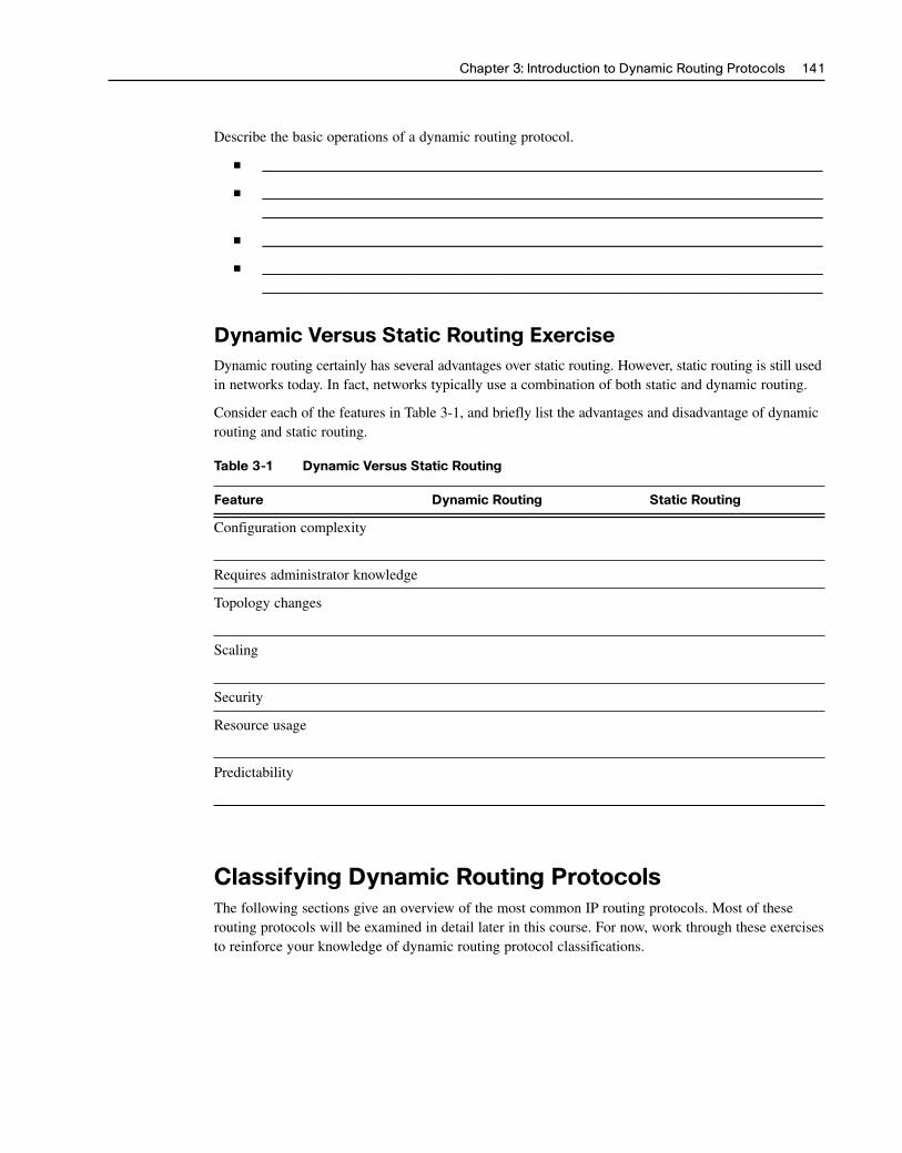
Dynamic Versus Static Routing ExerciseDynamic routing certainly has several advantages over static routing. However, static routing is still usedin networks today. In fact, networks typically use a combination of both static and dynamic routing.
Consider each of the features in Table 3-1, and briefly list the advantages and disadvantage of dynamicrouting and static routing.
Table 3-1 Dynamic Versus Static Routing
Feature Dynamic Routing Static Routing
Configuration complexity
Requires administrator knowledge
Topology changes
Scaling
Security
Resource usage
Predictability
Classifying Dynamic Routing ProtocolsThe following sections give an overview of the most common IP routing protocols. Most of theserouting protocols will be examined in detail later in this course. For now, work through these exercisesto reinforce your knowledge of dynamic routing protocol classifications.
Chapter 3: Introduction to Dynamic Routing Protocols 141
2044_ch03.qxp 10/31/07 2:20 PM Page 141

Dynamic Routing Protocols Classification ChartThe chart in Figure 3-2 is a succinct way to represent the major classifications of dynamic routingprotocols. For each of the empty boxes, write in the missing protocol.
Figure 3-2 Classifying Dynamic Routing Protocols
142 Routing Protocols and Concepts, CCNA Exploration Labs and Study Guide
Exterior GatewayProtocols
Dynamic RoutingProtocols
Interior GatewayProtocols
Distance VectorProtocols
Link-StateProtocols
Dynamic Routing Protocols Classification ExerciseRouting protocols can be classified into different groups according to their characteristics.
IGP and EGP
An (AS)—otherwise known as a —is a collection of routers under a common . Because the Internet is based on the
concept, two types of routing protocols are required:
■ (IGP)
■ (EGP)
Characteristics of IGPs and EGPs
An IGP is used to route an . IGPs for IP include ,, , , and . EGPs, on the other hand, are designed for use
different that are under the control of different . is the only currently viable EGP and is the routing protocol used by the . is
a protocol that can use many different to measure routes.
Distance Vector and Link-State
IGPs can be classified as two types:
■ routing protocols
■ routing protocols
2044_ch03.qxp 10/31/07 2:20 PM Page 142

Distance Vector Routing Protocol Operation
Distance vector means that routes are advertised as of distance and .Distance is defined in terms of a , such as hop count, and is simply the - router or . Distance vector protocols typically use the
- algorithm for the best-path route determination.
Some distance vector protocols send complete routing tables to all connected neighbors.In large networks, these routing updates can become enormous, causing significant traffic on the links.
Distance vector protocols use routers as sign posts along the path to the final destination. The onlyinformation a router knows about a remote network is the distance or to reach that networkand which path or to use to get there. Distance vector routing protocols do not have an actualmap of the network .
List four situations in which distance vector routing protocols are a good choice.
■ ____________________________________________________________________________
■ ________________________________________________________________________________________________________________________________________________________
■ ____________________________________________________________________________
■ ____________________________________________________________________________
Link-State Protocol Operation
In contrast to distance vector routing protocol operation, a router configured with a link-state routingprotocol can create a “complete view,” or , of the network. A link-state router uses
- information to create a map and to select the best path to all desti-nation networks in the .
Link-state routing protocols do not use updates. After the network has , alink-state update is only sent when there is a change in the topology.
List three situations in which link-state routing protocols are a good choice.
■ ____________________________________________________________________________
■ ____________________________________________________________________________
■ ____________________________________________________________________________
Classful and Classless Protocols
All routing protocols can also be classified as either
■ Classful routing protocols
■ Classless routing protocols
Classful Routing Protocols
What feature makes a routing protocol a classful routing protocol?
There are other limitations to classful routing protocols, including their inability to support networks—a topology that consists of a major network separating the subnets
of another major network.
Chapter 3: Introduction to Dynamic Routing Protocols 143
2044_ch03.qxp 10/31/07 2:20 PM Page 143
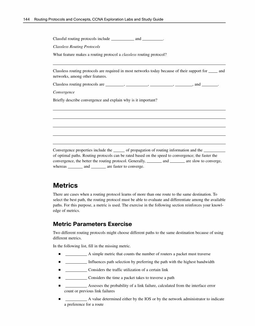
Classful routing protocols include and .
Classless Routing Protocols
What feature makes a routing protocol a classless routing protocol?
Classless routing protocols are required in most networks today because of their support for andnetworks, among other features.
Classless routing protocols are , , , , and .
Convergence
Briefly describe convergence and explain why is it important?
Convergence properties include the of propagation of routing information and the of optimal paths. Routing protocols can be rated based on the speed to convergence; the faster theconvergence, the better the routing protocol. Generally, and are slow to converge,whereas and are faster to converge.
MetricsThere are cases when a routing protocol learns of more than one route to the same destination. Toselect the best path, the routing protocol must be able to evaluate and differentiate among the availablepaths. For this purpose, a metric is used. The exercise in the following section reinforces your knowl-edge of metrics.
Metric Parameters ExerciseTwo different routing protocols might choose different paths to the same destination because of usingdifferent metrics.
In the following list, fill in the missing metric.
■ A simple metric that counts the number of routers a packet must traverse
■ Influences path selection by preferring the path with the highest bandwidth
■ Considers the traffic utilization of a certain link
■ Considers the time a packet takes to traverse a path
■ Assesses the probability of a link failure, calculated from the interface errorcount or previous link failures
■ A value determined either by the IOS or by the network administrator to indicatea preference for a route
144 Routing Protocols and Concepts, CCNA Exploration Labs and Study Guide
2044_ch03.qxp 10/31/07 2:20 PM Page 144

In the following list, fill in the missing metric or metrics for the routing protocol.
■ RIP: —Best path is chosen by the route with the lowest hop count.
■ IGRP and EIGRP: , , , and —Best path is chosenby the route with the smallest composite metric value calculated from these multiple parame-ters. By default, only and are used.
■ IS-IS and OSPF: —Best path is chosen by the route with the lowest . TheCisco implementation of OSPF uses .
Administrative DistancesBefore the routing process can determine which route to use when forwarding a packet, it must firstdetermine which routes to include in the routing table. In some cases, a router can learn a route to aremote network from more than one routing source. The exercises in the following sections reinforceyour knowledge of the concept of administrative distance.
Concept of Administrative Distance ExerciseA router might learn of a route to the same network from more than one . For example, a
route might have been configured for the same network/subnet mask that was learned dynam-ically by a dynamic routing protocol. Although less common, more than one dynamic routing protocolcan be deployed in the same network. Administrative distance (AD) defines the of a rout-ing source.
Administrative distance is an integer value from to . The the value the morepreferred the route source. An administrative distance of is the most preferred, which is the ADvalue for a network.
An administrative distance of means that the router will not believe the source of that routeand it will not be installed in the routing table.
On way to see the AD value for a route source is to look at the routing table. In Example 3-1, circlethe AD values for the route sources that show an AD value.
Example 3-1 Routing Table with AD Value
Chapter 3: Introduction to Dynamic Routing Protocols 145
R2# show ip route
<output omitted>
Gateway of last resort is not set
D 192.168.1.0/24 [90/2172416] via 192.168.2.1, 00:00:24, Serial0/0
C 192.168.2.0/24 is directly connected, Serial0/0/0
C 192.168.3.0/24 is directly connected, FastEthernet0/0
C 192.168.4.0/24 is directly connected, Serial0/0/1
R 192.168.5.0/24 [120/1] via 192.168.4.1, 00:00:08, Serial0/0/1
D 192.168.6.0/24 [90/2172416] via 192.168.2.1, 00:00:24, Serial0/0/0
R 192.168.7.0/24 [120/1] via 192.168.4.1, 00:00:08, Serial0/0/1
R 192.168.8.0/24 [120/2] via 192.168.4.1, 00:00:08, Serial0/0/1
2044_ch03.qxp 10/31/07 2:20 PM Page 145

What other command can be used to verify the administrative distance used by a routing protocol?
Notice that the directly connected networks in Example 3-1 do not show an administrative distance.What command would show the administrative distance (list as simply “distance”) for the 192.168.2.0route in R2’s routing table?
R2 might have knowledge of more networks than is shown in the routing table. What command willdisplay all the RIP routes learned by R2, whether or not the RIP route is installed in the routing table?
Routing Sources and Administrative Distance ExerciseTable 3-2 shows an incomplete chart of the different administrative distance values for various routingprotocols. Fill in the missing information.
Table 3-2 Default Administrative Distances
Route Source AD
Connected
EIGRP summary route 5
External BGP 20
Internal EIGRP
IGRP 100
110
IS-IS 115
120
External EIGRP 170
Internal BGP 200
Unknown 255
Identifying Elements of the Routing Table ExerciseThe purpose of this exercise is to practice how to correctly identify the route source, administrativedistance, and metric for a given route based on output from the show ip route command.
The output is not common for most routing tables. Running more than one routing protocol on thesame router is rare. Running three, as shown here, is more of an academic exercise and has value inthat it will help you learn to interpret the routing table output.
146 Routing Protocols and Concepts, CCNA Exploration Labs and Study Guide
2044_ch03.qxp 10/31/07 2:20 PM Page 146

From the show ip route information in Example 3-2, fill in missing spaces in Table 3-3.
Example 3-2 Multiple Routing Sources in the Routing Table
Chapter 3: Introduction to Dynamic Routing Protocols 147
R2# show ip route
Codes: C - connected, S - static, I - IGRP, R - RIP, M - mobile, B - BGP
D - EIGRP, EX - EIGRP external, O - OSPF, IA - OSPF inter area
N1 - OSPF NSSA external type 1, N2 - OSPF NSSA external type 2
E1 - OSPF external type 1, E2 - OSPF external type 2, E - EGP
i - IS-IS, L1 - IS-IS level-1, L2 - IS-IS level-2, ia - IS-IS inter area
* - candidate default, U - per-user static route, o - ODR
P - periodic downloaded static route
Gateway of last resort is not set
10.0.0.0/16 is subnetted, 1 subnets
S 10.4.0.0 is directly connected, Serial0/0
172.16.0.0/24 is subnetted, 3 subnets
C 172.16.1.0 is directly connected, FastEthernet0/0
C 172.16.2.0 is directly connected, Serial0/0
D 172.16.3.0 [90/2172416] via 172.16.2.1, 00:00:18, Serial0/0
C 192.168.1.0/24 is directly connected, Serial0/1
O 192.168.100.0/24 [110/65] via 172.16.2.1, 00:00:03, Serial0/0
O 192.168.110.0/24 [110/65] via 172.16.2.1, 00:00:03, Serial0/0
R 192.168.120.0/24 [120/1] via 172.16.2.1, 00:00:18, Serial0/0
Table 3-3 Route Sources, AD Values, and Metrics
Route Route Source AD Metric
10.4.0.0/16
172.16.1.0/24
172.16.2.0/24
172.16.3.0/24
192.168.1.0/24
192.168.100.0/24
192.168.110.0/24
192.168.120.0/24
2044_ch03.qxp 10/31/07 2:20 PM Page 147

Labs and Activities
Command ReferenceIn Table 3-4, record the command, including the correct router prompt, that fits the description.
Table 3-4 Commands for Chapter 3, Introduction to Dynamic Routing Protocols
Command Description
Displays all the routes known by RIP—even routes that are not currently in the routing table
Displays detailed information about dynamic routing processes currently running on the router
Displays detailed information about the route 172.16.3.0
Lab 3-1: Subnetting Scenario 1 (3.5.2)Upon completion of this lab, you will be able to
■ Determine the number of subnets needed
■ Determine the number of hosts needed
■ Design an appropriate addressing scheme
■ Assign addresses and subnet mask pairs to device interfaces and hosts
■ Examine the use of the available network address space
■ Determine how static routing could be applied to the network
Scenario
In this lab, you have been given the network address 192.168.9.0/24 to subnet and provide the IPaddressing for the network shown in Figure 3-3. The network has the following addressing require-ments:
■ The BRANCH1 LAN 1 will require 10 host IP addresses.
■ The BRANCH1 LAN 2 will require 10 host IP addresses.
■ The BRANCH2 LAN 1 will require 10 host IP addresses.
■ The BRANCH2 LAN 2 will require 10 host IP addresses.
■ The HQ LAN will require 20 host IP addresses.
■ The link from HQ to BRANCH1 will require an IP address for each end of the link.
■ The link from HQ to BRANCH2 will require an IP address for each end of the link.
148 Routing Protocols and Concepts, CCNA Exploration Labs and Study Guide
2044_ch03.qxp 10/31/07 2:20 PM Page 148

Figure 3-3 Topology Diagram for Subnetting Scenario 1
Chapter 3: Introduction to Dynamic Routing Protocols 149
PC1
PC4
PC5
PC2
PC3
HQ
B1 B2Fa0/1Fa0/0
Fa0/0Fa0/1S0/0/1
S0/0/1DCE
Fa0/1
S0/0/0
S0/0/0DCE
Table 3-5 provides a rough outline for the IP addresses, subnet masks, and default gateways (whereapplicable) for the devices shown in the network topology of Figure 3-3.
Table 3-5 Addressing Table for Lab 3-1
Device Interface IP Address Subnet Mask Default Gateway
HQ Fa0/0 —
S0/0/0 —
S0/0/1 —
BRANCH1 Fa0/0 —
Fa0/1 —
S0/0/0 —
BRANCH2 Fa0/0 —
Fa0/1 —
S0/0/1 —
PC1 NIC
PC2 NIC
PC3 NIC
PC4 NIC
PC5 NIC
2044_ch03.qxp 10/31/07 2:20 PM Page 149

Task 1: Examine the Network RequirementsExamine the network requirements and answer the questions below. Keep in mind that IP addresseswill be needed for each of the LAN interfaces.
How many subnets are needed?
What is the maximum number of IP addresses that are needed for a single subnet?
How many IP addresses are needed for each of the branch LANs?
What is the total number of IP addresses that are needed?
Task 2: Design an IP Addressing SchemeStep 1. Subnet the 192.168.9.0 network into the appropriate number of subnets.
What will the subnet mask be for the subnetworks?
How many usable host IP addresses are there per subnet?
Fill in Table 3-6 with the subnet information.
Table 3-6 Subnetting Chart for Lab 3-1
Subnet Subnet First Usable Last Usable Broadcast Number Address Host Address Host Address Address
0
1
2
3
4
5
6
7
Step 2. Assign the subnets to the network shown in the topology diagram in Figure 3-3.
When assigning the subnets, keep in mind that routing will need to occur to allow infor-mation to be sent throughout the network. The subnets will be assigned to the networks toallow route summarization on each of the routers.
1. Assign subnet 1 to the BRANCH2 LAN 2:
2. Assign subnet 2 to BRANCH2 LAN 1 subnet address:
3. Assign subnet 3 to link from HQ to BRANCH2 subnet address:
4. Assign subnet 4 to HQ LAN subnet address:
5. Assign subnet 5 to link from HQ to BRANCH1 subnet address:
6. Assign subnet 6 to BRANCH1 LAN 2 subnet address:
7. Assign subnet 7 to BRANCH1 LAN 1 subnet address:
150 Routing Protocols and Concepts, CCNA Exploration Labs and Study Guide
2044_ch03.qxp 10/31/07 2:20 PM Page 150

Task 3: Assign IP Addresses to the Network DevicesAssign the appropriate addresses to the device interfaces. Document the addresses to be used in Table3-5 shown earlier.
Step 1. Assign addresses to the HQ router.
1. Assign the first valid host address in the HQ LAN subnet to the LAN interface.
2. Assign the first valid host address in the link from HQ to BRANCH1 subnet to theS0/0/0 interface.
3. Assign the first valid host address in the link from HQ to BRANCH2 subnet to theS0/0/1 interface.
Step 2. Assign addresses to the BRANCH1 router.
1. Assign the first valid host address in the BRANCH1 LAN 1 subnet to the Fa0/0LAN interface.
2. Assign the first valid host address in the BRANCH1 LAN 2 subnet to the Fa0/1LAN interface.
3. Assign the last valid host address in the link from HQ to BRANCH1 subnet to theWAN interface.
Step 3. Assign addresses to the BRANCH2 router.
1. Assign the first valid host address in the BRANCH2 LAN 1 subnet to the Fa0/0LAN interface.
2. Assign the first valid host address in the BRANCH2 LAN 2 subnet to the Fa0/1LAN interface.
3. Assign the last valid host address in the link from HQ to BRANCH2 subnet to theWAN interface.
Step 4. Assign addresses to the host PCs.
1. Assign the last valid host address in the HQ LAN subnet to PC1.
2. Assign the last valid host address in the BRANCH1 LAN 1 subnet to PC2.
3. Assign the last valid host address in the BRANCH1 LAN 2 subnet to PC3.
4. Assign the last valid host address in the BRANCH2 LAN 1 subnet to PC4.
5. Assign the last valid host address in the BRANCH2 LAN 2 subnet to PC5.
Task 4: Test the Network DesignYou can now open the file LSG02-Lab352.pka on the CD-ROM that accompanies this book to applyand verify your addressing scheme. Check to see that all devices on directly connected networks canping each other.
Chapter 3: Introduction to Dynamic Routing Protocols 151
Packet Tracer Companion
2044_ch03.qxp 10/31/07 2:20 PM Page 151

Task 5: ReflectionHow many IP address in the 192.168.9.0 network are wasted in this design?
What would the command be to add a default static route on the WAN interface of the BRANCH1router?
Can both of the BRANCH1 LANs be summarized into one route on the HQ router?
What would be the command used to add this summary route to the routing table?
Can both of the BRANCH2 LANs be summarized into one route on the HQ router?
What would be the command used to add this summary route to the routing table?
Can the HQ LAN and both of the BRANCH1 LANs be summarized into one route on the BRANCH2router? This summarized route should also include the link between the HQ and BRANCH1 routers.
What would be the command used to add this summary route to the routing table?
Lab 3-2: Subnetting Scenario 2 (3.5.3)Upon completion of this lab, you will be able to
■ Determine the number of subnets needed
■ Determine the number of hosts needed
■ Design an appropriate addressing scheme
■ Assign addresses and subnet mask pairs to device interfaces and hosts
■ Examine the use of the available network address space
■ Determine how static routing could be applied to the network
Scenario
In this lab, you have been given the network address 172.16.0.0/16 to subnet and provide the IPaddressing for the network shown in Figure 3-4. The network has the following addressing require-ments:
■ The Branch 1 LAN will require 100 host IP addresses.
■ The Branch 2 LAN will require 100 host IP addresses.
■ The Branch 3 LAN will require 100 host IP addresses.
■ The Branch 4 LAN will require 100 host IP addresses.
■ The West LAN will require 400 hosts.
■ The East LAN will require 400 hosts.
152 Routing Protocols and Concepts, CCNA Exploration Labs and Study Guide
2044_ch03.qxp 10/31/07 2:20 PM Page 152

■ The HQ LAN will require 500 host IP addresses.
■ The links between each of the routers will require an IP address for each end of the link.
The IP addresses for the link from the HQ router to the ISP have already been assigned. The Serial0/1/0 address of the HQ router is 209.165.200.226/27. The IP address of the Serial 0/0/0 interface ofthe ISP router is 209.165.200.225/27.
Figure 3-4 Topology Diagram for Subnetting Scenario 2
Chapter 3: Introduction to Dynamic Routing Protocols 153
Fa0/0
Fa0/0 Fa0/0 Fa0/0 Fa0/0
S0/0/1DCE
S0/0/0DCE
S0/0/0DCE
S0/1/0
S0/0/0 S0/0/0
Fa0/0
S0/0/0DCE
S0/1/0DCE
S0/0/1DCE
Fa0/0
S0/0/1DCE
S0/1/0DCE
S0/0/1DCE
S0/0/1DCE
S0/1/0
S0/0/0 S0/0/0
S0/0/1 S0/0/1
S0/0/0 S0/0/0
WEST EAST
B3B1 B2 B4
PC1
PC2 PC3
PC6PC4 PC5 PC7
HQ
ISP
209.165.200.224/27
Table 3-7 provides a rough outline for the IP addresses, subnet masks, and default gateways (whereapplicable) for the devices shown in the network topology shown in Figure 3-4.
Table 3-7 Addressing Table for Lab 3-2
Device Interface IP Address Subnet Mask Default Gateway
HQ Fa0/0 —
S0/0/0 —
S0/0/1 —
S0/1/0 209.165.200.226 255.255.255.224 —
continues
2044_ch03.qxp 10/31/07 2:20 PM Page 153
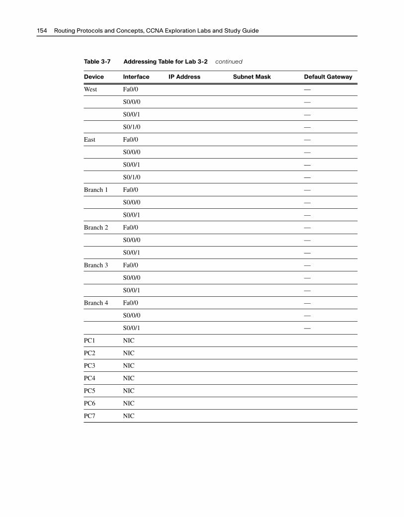
Table 3-7 Addressing Table for Lab 3-2 continued
Device Interface IP Address Subnet Mask Default Gateway
West Fa0/0 —
S0/0/0 —
S0/0/1 —
S0/1/0 —
East Fa0/0 —
S0/0/0 —
S0/0/1 —
S0/1/0 —
Branch 1 Fa0/0 —
S0/0/0 —
S0/0/1 —
Branch 2 Fa0/0 —
S0/0/0 —
S0/0/1 —
Branch 3 Fa0/0 —
S0/0/0 —
S0/0/1 —
Branch 4 Fa0/0 —
S0/0/0 —
S0/0/1 —
PC1 NIC
PC2 NIC
PC3 NIC
PC4 NIC
PC5 NIC
PC6 NIC
PC7 NIC
154 Routing Protocols and Concepts, CCNA Exploration Labs and Study Guide
2044_ch03.qxp 10/31/07 2:20 PM Page 154

Task 1: Examine the Network RequirementsExamine the network requirements and answer the questions that follow. Keep in mind that IPaddresses will be needed for each of the LAN interfaces.
How many subnets are needed?
What is the maximum number of IP addresses that are needed for a single subnet?
How many IP addresses are needed for each of the branch LANs?
How many IP addresses are needed for all the connections between routers?
What is the total number of IP addresses that are needed?
Task 2: Design an IP Addressing SchemeStep 1. Subnet the 172.16.0.0 network into the appropriate number of subnets.
What will the subnet mask be for the subnetworks?
How many usable host IP addresses are there per subnet?
Fill in Table 3-8 with the subnet information.
Table 3-8 Subnetting Chart for Lab 3-2
Subnet Subnet IP First Usable Last Usable Broadcast Number Host IP Host IP Address
0
1
2
3
4
5
6
7
8
9
10
11
12
13
14
15
Chapter 3: Introduction to Dynamic Routing Protocols 155
2044_ch03.qxp 10/31/07 2:20 PM Page 155

Step 2. Assign the subnets to the network shown in the topology diagram in Figure 3-4.
When assigning the subnets, keep in mind that routing will need to occur to allow infor-mation to be sent throughout the network. The subnets will be assigned to the networks toallow route summarization on each of the routers.
1. Assign subnet 1 to the Branch 1 LAN subnet:
2. Assign subnet 2 to the Branch 2 LAN subnet:
3. Assign subnet 3 to the link between the Branch 1 and Branch 2 routers:
4. Assign subnet 4 to the link between the Branch 1 and West routers:
5. Assign subnet 5 to the link between the Branch 2 and West routers:
6. Assign subnet 6 to the West LAN subnet:
7. Assign subnet 7 to the link between the West and HQ routers:
8. Assign subnet 8 to the HQ LAN subnet:
9. Assign subnet 9 to the link between the HQ and East routers:
10. Assign subnet 10 to the East LAN subnet:
11. Assign subnet 11 to the link between the Branch 3 and East routers:
12. Assign subnet 12 to the link between the Branch 4 and East routers:
13. Assign subnet 13 to the link between the Branch 3 and Branch 4 routers:
14. Assign subnet 14 to the Branch 3 LAN subnet:
15. Assign subnet 15 to the Branch 4 LAN subnet:
Task 3: Assign IP Addresses to the Network DevicesAssign the appropriate addresses to the device interfaces. Document the addresses to be used in Table 3-7shown earlier.
Step 1. Assign addresses to the HQ router.
1. Assign the first valid host address in the HQ LAN subnet to the LAN interface.
2. Assign the first valid host address in the link from HQ to West subnet to the S0/0/0interface.
3. Assign the first valid host address in the link from HQ to East subnet to the S0/0/1interface.
Step 2. Assign addresses to the West router.
1. Assign the first valid host address in the West LAN subnet to the LAN interface.
2. Assign the last valid host address in the link from HQ to West subnet to the S0/0/0interface.
3. Assign the first valid host address in the link from West to Branch 1 subnet to theS0/0/1 interface.
156 Routing Protocols and Concepts, CCNA Exploration Labs and Study Guide
2044_ch03.qxp 10/31/07 2:20 PM Page 156
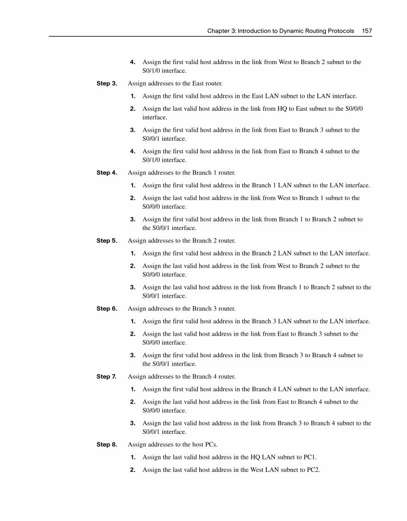
4. Assign the first valid host address in the link from West to Branch 2 subnet to theS0/1/0 interface.
Step 3. Assign addresses to the East router.
1. Assign the first valid host address in the East LAN subnet to the LAN interface.
2. Assign the last valid host address in the link from HQ to East subnet to the S0/0/0interface.
3. Assign the first valid host address in the link from East to Branch 3 subnet to theS0/0/1 interface.
4. Assign the first valid host address in the link from East to Branch 4 subnet to theS0/1/0 interface.
Step 4. Assign addresses to the Branch 1 router.
1. Assign the first valid host address in the Branch 1 LAN subnet to the LAN interface.
2. Assign the last valid host address in the link from West to Branch 1 subnet to theS0/0/0 interface.
3. Assign the first valid host address in the link from Branch 1 to Branch 2 subnet tothe S0/0/1 interface.
Step 5. Assign addresses to the Branch 2 router.
1. Assign the first valid host address in the Branch 2 LAN subnet to the LAN interface.
2. Assign the last valid host address in the link from West to Branch 2 subnet to theS0/0/0 interface.
3. Assign the last valid host address in the link from Branch 1 to Branch 2 subnet to theS0/0/1 interface.
Step 6. Assign addresses to the Branch 3 router.
1. Assign the first valid host address in the Branch 3 LAN subnet to the LAN interface.
2. Assign the last valid host address in the link from East to Branch 3 subnet to theS0/0/0 interface.
3. Assign the first valid host address in the link from Branch 3 to Branch 4 subnet tothe S0/0/1 interface.
Step 7. Assign addresses to the Branch 4 router.
1. Assign the first valid host address in the Branch 4 LAN subnet to the LAN interface.
2. Assign the last valid host address in the link from East to Branch 4 subnet to theS0/0/0 interface.
3. Assign the last valid host address in the link from Branch 3 to Branch 4 subnet to theS0/0/1 interface.
Step 8. Assign addresses to the host PCs.
1. Assign the last valid host address in the HQ LAN subnet to PC1.
2. Assign the last valid host address in the West LAN subnet to PC2.
Chapter 3: Introduction to Dynamic Routing Protocols 157
2044_ch03.qxp 10/31/07 2:20 PM Page 157

3. Assign the last valid host address in the East 1 LAN subnet to PC3.
4. Assign the last valid host address in the Branch 1 LAN subnet to PC4.
5. Assign the last valid host address in the Branch 2 LAN subnet to PC5.
6. Assign the last valid host address in the Branch 3 LAN subnet to PC6.
7. Assign the last valid host address in the Branch 4 LAN subnet to PC7.
Task 4: Test the Network DesignYou can now open the file LSG02-Lab353.pka on the CD-ROM that accompanies this book to applyand verify your addressing scheme. Check to see that all devices on directly connected networks canping each other.
Task 5: ReflectionHow many IP addresses in the 172.16.0.0 network are wasted in this design?
What would be the command to add a default static route for your entire network design from the HQrouter to the ISP router?
Can the West, Branch 1, and Branch 2 networks be summarized into one route on the HQ router? Thissummarized route should also include the serial links that connect the West, Branch 1, and Branch 2routers.
What would be the command used to add this summary route to the routing table?
Can the East, Branch 3, and Branch 4 networks be summarized into one route on the HQ router? Thissummarized route should also include the serial links that connect the East, Branch 3, and Branch 4routers.
What would be the command used to add this summary route to the routing table?
What would be the command to add a default static route on the West router to send traffic for allunknown destinations to the HQ router?
What would be the command to add a default static route on the East router to send traffic for allunknown destinations to the HQ router?
Can the Branch 1 and Branch 2 networks be summarized into one route on the West router? This sum-marized route should also include the serial link that connects the Branch 1 and Branch 2 routers.
What would be the command to add this summary route to the routing table? Use the S0/0/1 interfaceof the West router as the exit interface.
158 Routing Protocols and Concepts, CCNA Exploration Labs and Study Guide
Packet Tracer Companion
2044_ch03.qxp 10/31/07 2:20 PM Page 158

Can the Branch 3 and Branch 4 networks be summarized into one route on the East router? This sum-marized route should also include the serial link that connects the Branch 3 and Branch 4 routers.
What would be the command to add this summary route to the routing table? Use the S0/0/1 interfaceof the East router as the exit interface.
The Branch 1 router requires a static route for traffic destined for Branch 2. All other traffic should besent to the West router using a default static route. What commands would be used to accomplish this?
The Branch 2 router requires a static route for traffic destined for Branch 1. All other traffic should besent to the West router using a default static route. What commands would be used to accomplish this?
The Branch 3 router requires a static route for traffic destined for Branch 4. All other traffic should besent to the East router using a default static route. What commands would be used to accomplish this?
The Branch 4 router requires a static route for traffic destined for Branch 3. All other traffic should besent to the East router using a default static route. What commands would be used to accomplish this?
Lab 3-3: Subnetting Scenario 3 (3.5.4)Upon completion of this lab, you will be able to
■ Determine the number of subnets needed
■ Determine the number of hosts needed
■ Design an appropriate addressing scheme
■ Conduct research to find a possible solution
Scenario
In this lab, you have been given the network address 192.168.1.0/24 to subnet and provide the IPaddressing for the network shown in Figure 3-5. The network has the following addressing requirements:
■ The BRANCH1 LAN 1 will require 15 host IP addresses.
Chapter 3: Introduction to Dynamic Routing Protocols 159
2044_ch03.qxp 10/31/07 2:20 PM Page 159

■ The BRANCH1 LAN 2 will require 15 host IP addresses.
■ The BRANCH2 LAN 1 will require 15 host IP addresses.
■ The BRANCH2 LAN 2 will require 15 host IP addresses.
■ The HQ LAN will require 30 host IP addresses.
■ The link from HQ to BRANCH1 will require an IP address for each end of the link.
■ The link from HQ to BRANCH2 will require an IP address for each end of the link.
■ The link from HQ to Branch 3 will require an IP address for each end of the link.
Figure 3-5 Topology Diagram for Subnetting Scenario 3
Table 3-9 provides a rough outline for you to assign the IP addresses, subnet masks, and default gate-
160 Routing Protocols and Concepts, CCNA Exploration Labs and Study Guide
PC1
PC4
PC5
PC2
PC3
HQ
B1 B2Fa0/1Fa0/0
Fa0/0Fa0/1S0/0/1
S0/0/1
S0/0/1DCE
Fa0/1
S0/0/0
S0/0/0DCE
ways (where applicable) for the devices shown in the network topology of Figure 3-5.
Table 3-9 Addressing Table for Lab 3-3
Device Interface IP Address Subnet Mask Default Gateway
HQ Fa0/1 —
S0/0/0 —
S0/0/1 —
BRANCH1 Fa0/0 —
Fa0/1 —
S0/0/0 —
S0/0/1 —
BRANCH2 Fa0/0 —
Fa0/1 —
S0/0/0 —
S0/0/1 —
2044_ch03.qxp 10/31/07 2:20 PM Page 160

Device Interface IP Address Subnet Mask Default Gateway
PC1 NIC
PC2 NIC
PC3 NIC
PC4 NIC
PC5 NIC
Task 1: Examine the Network RequirementsExamine the network requirements and answer the questions that follow. Keep in mind that IPaddresses will be needed for each of the LAN interfaces.
How many subnets are needed?
What is the maximum number of IP addresses that are needed for a single subnet?
How many IP addresses are needed for each of the branch LANs?
What is the total number of IP addresses that are needed?
Task 2: Design an IP Addressing SchemeSubnet the 192.168.1.0/24 network into the appropriate number of subnets.
Can the 192.168.1.0/24 network be subnetted to fit the network requirements?
If the “number of subnets” requirement is met, what is the maximum number of hosts per subnet?
If the “maximum number of hosts” requirement is met, what is the number of subnets that will beavailable to use?
Task 3: ReflectionYou do not have enough address space to implement an addressing scheme. Research this problemand propose a possible solution. Increasing the size of your original address space is not an acceptablesolution. (Hint: We will discuss solutions to this problem in Chapter 6, “VLSM and CIDR.”)
Attempt to implement your solution using Packet Tracer. You can now open the file LSG02-Lab354.pka on the CD-ROM that accompanies this book to apply and verify your addressing scheme.Check to see that all devices on directly connected networks can ping each other.
Successful implementation of a solution requires that
■ Only the 192.168.1.0/24 address space is used.
■ PCs and routers can ping all IP addresses.
Chapter 3: Introduction to Dynamic Routing Protocols 161
Packet Tracer Companion
2044_ch03.qxp 10/31/07 2:20 PM Page 161

Packet Tracer Skills Integration Challenge
IntroductionThis activity focuses on subnetting skills, basic device configurations, and static routing. After youconfigure all devices, test for end-to-end connectivity and examine your configuration. Open the fileLSG02-PTSkills3.pka on the CD-ROM that accompanies this book. Use the topology in Figure 3-6and the addressing table in Table 3-10 to document your design.
Upon completion of this lab, you will be able to
■ Design and document an addressing scheme based on requirements
■ Select appropriate equipment and cable the devices
■ Apply a basic configuration to the devices
■ Configure static and default routing
■ Verify full connectivity between all devices in the topology
Figure 3-6 Packet Tracer Skills Integration Challenge Topology
162 Routing Protocols and Concepts, CCNA Exploration Labs and Study Guide
Packet Tracer Challenge
ISP
S0/0/0
30 Hosts209.165.200.224/30
209.165.201.0/30
10.0.0.0/30
10.0.0.8/30
10.0.0.4/30
Fa0/0
S0/0/0
S0/1/1
S0/0/0
S0/0/1S0/1/0
S0/0
S0/0/0
Fa0/0
Fa0/1
HQ
B1 Address Space192.168.1.0/24
B3 Address Space172.20.0.0/17
HQ Address Space192.168.0.128/25
Fa1/0Fa0/1
Fa0/0 Fa1/1B2
1,000 Hosts
1,000 Hosts 1,000 Hosts
1,000 Hosts
B1Fa1/1Fa1/0
Fa0/0Fa0/1
60 Hosts
60 Hosts
60 Hosts
60 Hosts
30 Hosts
Fa0/0Fa0/1
Fa1/1 Fa1/0
5,000 Hosts
5,000 Hosts
5,000 Hosts
5,000 Hosts
B2 Address Space172.16.0.0/20
B3
2044_ch03.qxp 10/31/07 2:20 PM Page 162

Table 3-10 provides a rough outline for you to assign the IP addresses and subnet masks for thedevices shown in the network topology of Figure 3-6.
Table 3-10 Addressing Table for Packet Tracer Skills Integration Challenge
Device Interface IP Address Subnet Mask
HQ Fa0/0
Fa0/1
S0/0/0 10.0.0.1 255.255.255.252
S0/0/1 10.0.0.5 255.255.255.252
S0/1/0 10.0.0.9 255.255.255.252
S0/1/1 209.165.201.2 255.255.255.252
B1 Fa0/0
Fa0/1
Fa1/0
Fa1/1
S0/0/0 10.0.0.2 255.255.255.252
B2 Fa0/0
Fa0/1
Fa1/0
Fa1/1
S0/0/0 10.0.0.6 255.255.255.252
B3 Fa0/0
Fa0/1
Fa1/0
Fa1/1
S0/0/0 10.0.0.10 255.255.255.252
ISP S0/0/0 209.165.201.1 255.255.255.252
Fa0/0 209.165.200.225 255.255.255.252
Web Server NIC 209.165.200.226 255.255.255.252
Task 1: Design and Document an Addressing SchemeStep 1. Design an addressing scheme.
Based on the network requirements shown in Figure 3-6, design an appropriate addressingscheme.
Chapter 3: Introduction to Dynamic Routing Protocols 163
2044_ch03.qxp 10/31/07 2:20 PM Page 163
■ The HQ, B1, B2, and B3 routers each have an address space. Subnet the address spacebased on the host requirements.
■ For each address space, assign subnet 0 to the Fa0/0 LAN, subnet 1 to the Fa0/1, andso on.
Step 2. Document the addressing scheme.
■ Use Table 3-10 to document the IP addresses and subnet masks. Assign the first IPaddress to the router interface.
■ For the WAN links, assign the first IP address to HQ.
Task 2: Apply a Basic ConfigurationUsing your documentation, configure the routers with basic configurations including addressing andhost names. Use cisco as the line passwords and class as the secret password. Use 64000 as the clockrate. ISP is the DCE in its WAN link to HQ, and HQ is the DCE for all other WAN links.
Task 3: Configure Static and Default RoutingConfigure static and default routing using the exit interface argument, according to the following criteria:
■ HQ should have three static routes and one default route.
■ B1, B2, and B3 should have one default route.
■ ISP should have seven static routes. This will include the three WAN links between HQ and thebranch routers B1, B2, and B3.
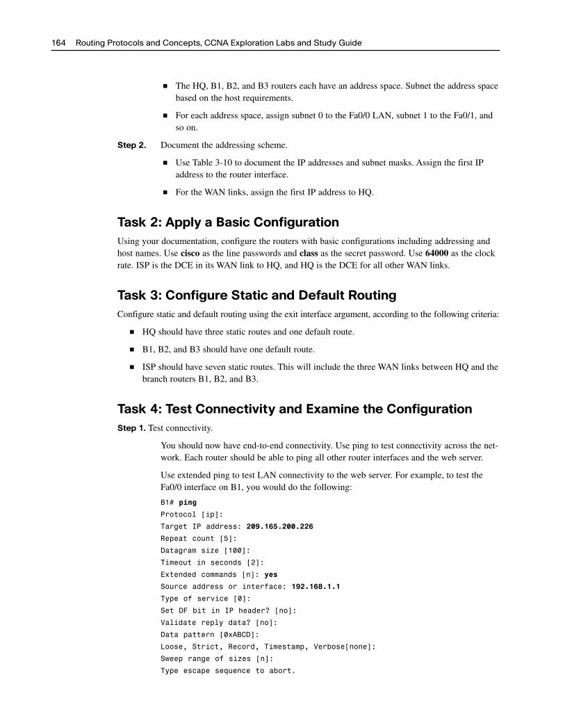
Task 4: Test Connectivity and Examine the ConfigurationStep 1. Test connectivity.
You should now have end-to-end connectivity. Use ping to test connectivity across the net-work. Each router should be able to ping all other router interfaces and the web server.
Use extended ping to test LAN connectivity to the web server. For example, to test theFa0/0 interface on B1, you would do the following:
B1# ping
Protocol [ip]:
Target IP address: 209.165.200.226
Repeat count [5]:
Datagram size [100]:
Timeout in seconds [2]:
Extended commands [n]: yes
Source address or interface: 192.168.1.1
Type of service [0]:
Set DF bit in IP header? [no]:
Validate reply data? [no]:
Data pattern [0xABCD]:
Loose, Strict, Record, Timestamp, Verbose[none]:
Sweep range of sizes [n]:
Type escape sequence to abort.
164 Routing Protocols and Concepts, CCNA Exploration Labs and Study Guide
2044_ch03.qxp 10/31/07 2:20 PM Page 164

Sending 5, 100-byte ICMP Echos to 209.165.200.226, timeout is 2 seconds:
Packet sent with a source address of 192.168.1.1
!!!!!
Success rate is 100 percent (5/5), round-trip min/avg/max = 67/118/138 ms
Troubleshoot until pings are successful.
Step 2. Examine the configuration.
Use verification commands to make sure that your configurations are complete.
Chapter 3: Introduction to Dynamic Routing Protocols 165
2044_ch03.qxp 10/31/07 2:20 PM Page 165