Introduction to DISH Pro Technology...
20
TECHNOLOGIES CORPORATION A Part of the EchoStar Group of Companies ©2004, EchoStar Technologies Corp. All rights reserved. REV 8/24/04 INTRODUCTION TO DISH PRO TECHNOLOGY
Transcript of Introduction to DISH Pro Technology...
T E C H N O L O G I E S C O R P O R A T I O N
A Part of the EchoStar Group of Companies
©2004, EchoStar Technologies Corp. All rights reserved.
REV 8/24/04
INTRODUCTION TO DISH PRO
TECHNOLOGY
INTRO TO DISH PRO TECHNOLOGY Rev 8/24/04
Page 2 of 20 ©2004, EchoStar Technologies Corp. All rights reserved.
Introduction to DISH Pro Technology
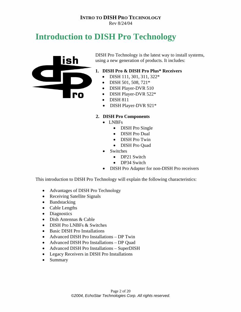
DISH Pro Technology is the latest way to install systems, using a new generation of products. It includes: 1. DISH Pro & DISH Pro Plus* Receivers
• DISH 111, 301, 311, 322* • DISH 501, 508, 721* • DISH Player-DVR 510 • DISH Player-DVR 522* • DISH 811 • DISH Player-DVR 921*
2. DISH Pro Components
• LNBFs • DISH Pro Single • DISH Pro Dual • DISH Pro Twin • DISH Pro Quad
• Switches • DP21 Switch • DP34 Switch
• DISH Pro Adapter for non-DISH Pro receivers This introduction to DISH Pro Technology will explain the following characteristics:
• Advantages of DISH Pro Technology • Receiving Satellite Signals • Bandstacking • Cable Lengths • Diagnostics • Dish Antennas & Cable • DISH Pro LNBFs & Switches • Basic DISH Pro Installations • Advanced DISH Pro Installations – DP Twin • Advanced DISH Pro Installations – DP Quad • Advanced DISH Pro Installations – SuperDISH • Legacy Receivers in DISH Pro Installations • Summary
INTRO TO DISH PRO TECHNOLOGY Rev 8/24/04
Page 3 of 20 ©2004, EchoStar Technologies Corp. All rights reserved.
Abbreviations used throughout this document: Name Abbreviation DISH Pro DP DISH Pro Plus DP Plus DISH Pro Adapter DP Adapter Kilohertz KHz Megahertz MHz Gigahertz GHz
Advantages of DISH Pro Technology Advantages of DISH Pro technology include:
• Simplified installation • Installations use just ONE cable for both polarities (“bandstacking”). • Switches do not require a power inserter.
• Installations allow increased cable lengths - up to 200 feet between the LNBF and the receiver.
• Advanced diagnostics and improved reliability. • Each component AND its connection status are displayed.
INTRO TO DISH PRO TECHNOLOGY Rev 8/24/04
Page 4 of 20 ©2004, EchoStar Technologies Corp. All rights reserved.
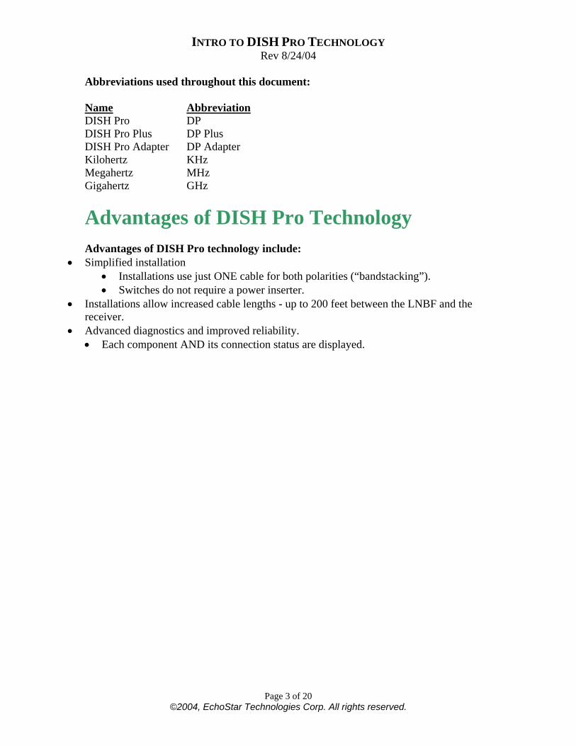
Receiving Satellite Signals When signals from the satellite transponder are transmitted to the dish antenna, they are sent in one of two patterns, called polarities. One polarity is used for odd-numbered transponders, and the other opposite polarity is used for even transponders. An example of circular polarity, used on our DBS satellites, is shown here.
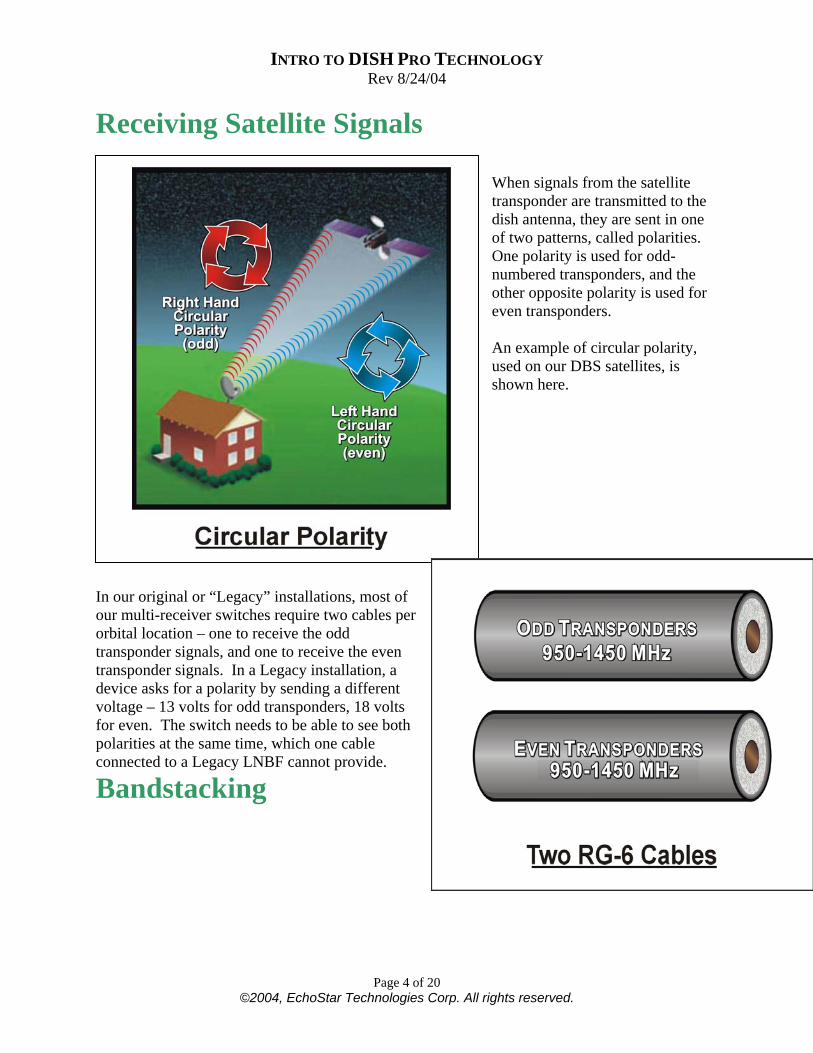
In our original or “Legacy” installations, most of our multi-receiver switches require two cables per orbital location – one to receive the odd transponder signals, and one to receive the even transponder signals. In a Legacy installation, a device asks for a polarity by sending a different voltage – 13 volts for odd transponders, 18 volts for even. The switch needs to be able to see both polarities at the same time, which one cable connected to a Legacy LNBF cannot provide.
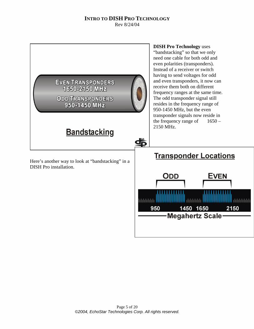
Bandstacking
INTRO TO DISH PRO TECHNOLOGY Rev 8/24/04
Page 5 of 20 ©2004, EchoStar Technologies Corp. All rights reserved.
DISH Pro Technology uses “bandstacking” so that we only need one cable for both odd and even polarities (transponders). Instead of a receiver or switch having to send voltages for odd and even transponders, it now can receive them both on different frequency ranges at the same time. The odd transponder signal still resides in the frequency range of 950-1450 MHz, but the even transponder signals now reside in the frequency range of 1650 – 2150 MHz.
Here’s another way to look at “bandstacking” in a DISH Pro installation.
INTRO TO DISH PRO TECHNOLOGY Rev 8/24/04
Page 6 of 20 ©2004, EchoStar Technologies Corp. All rights reserved.
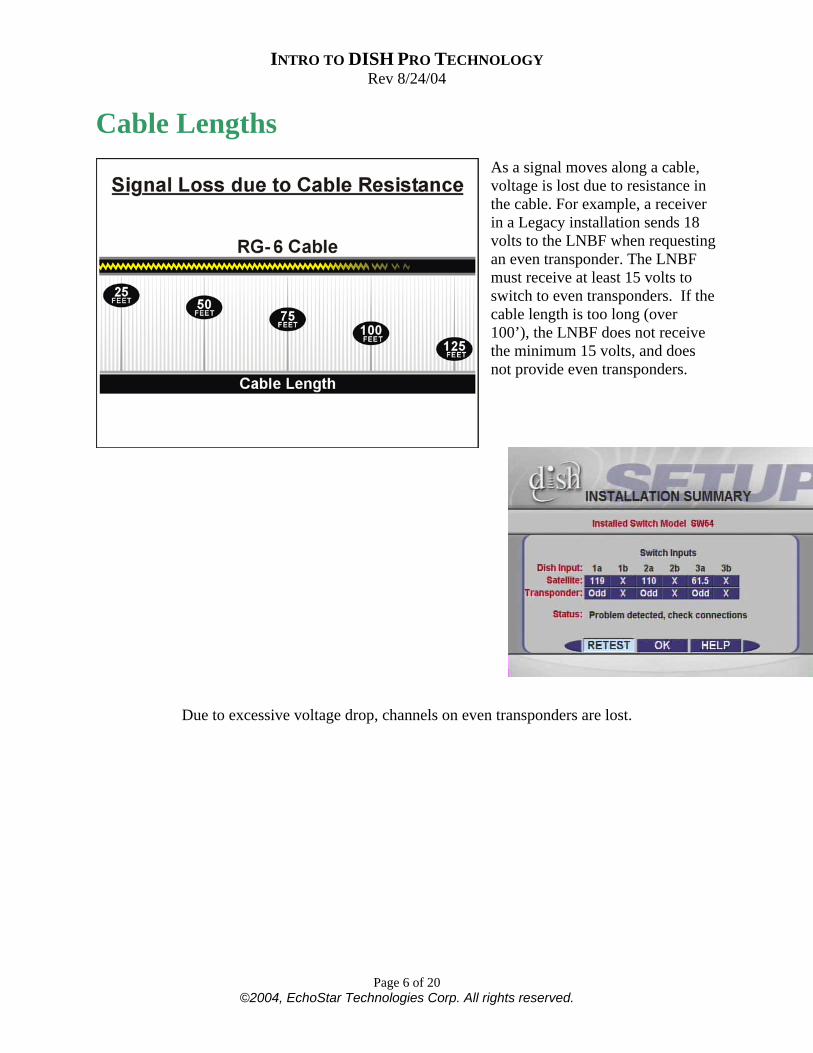
Cable Lengths
As a signal moves along a cable, voltage is lost due to resistance in the cable. For example, a receiver in a Legacy installation sends 18 volts to the LNBF when requesting an even transponder. The LNBF must receive at least 15 volts to switch to even transponders. If the cable length is too long (over 100’), the LNBF does not receive the minimum 15 volts, and does not provide even transponders.
Due to excessive voltage drop, channels on even transponders are lost.
INTRO TO DISH PRO TECHNOLOGY Rev 8/24/04
Page 7 of 20 ©2004, EchoStar Technologies Corp. All rights reserved.
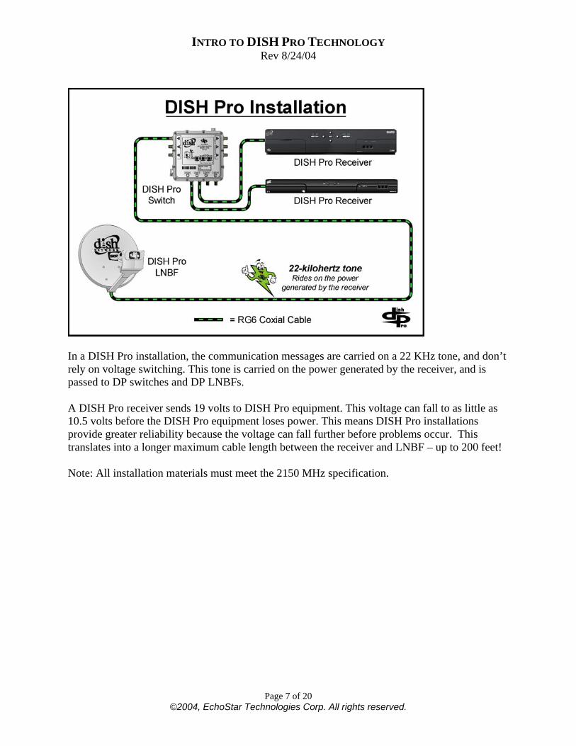
In a DISH Pro installation, the communication messages are carried on a 22 KHz tone, and don’t rely on voltage switching. This tone is carried on the power generated by the receiver, and is passed to DP switches and DP LNBFs. A DISH Pro receiver sends 19 volts to DISH Pro equipment. This voltage can fall to as little as 10.5 volts before the DISH Pro equipment loses power. This means DISH Pro installations provide greater reliability because the voltage can fall further before problems occur. This translates into a longer maximum cable length between the receiver and LNBF – up to 200 feet! Note: All installation materials must meet the 2150 MHz specification.
INTRO TO DISH PRO TECHNOLOGY Rev 8/24/04
Page 8 of 20 ©2004, EchoStar Technologies Corp. All rights reserved.
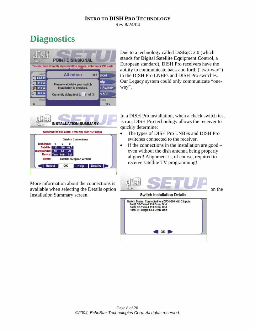
Diagnostics Due to a technology called DiSEqC 2.0 (which stands for Digital Satellite Equipment Control, a European standard), DISH Pro receivers have the ability to communicate back and forth (“two-way”) to the DISH Pro LNBFs and DISH Pro switches. Our Legacy system could only communicate “one-way”. In a DISH Pro installation, when a check switch test is run, DISH Pro technology allows the receiver to quickly determine: • The types of DISH Pro LNBFs and DISH Pro
switches connected to the receiver. • If the connections in the installation are good –
even without the dish antenna being properly aligned! Alignment is, of course, required to receive satellite TV programming!
More information about the connections is available when selecting the Details option on the Installation Summary screen.
INTRO TO DISH PRO TECHNOLOGY Rev 8/24/04
Page 9 of 20 ©2004, EchoStar Technologies Corp. All rights reserved.
Dish Antennas & Cable DISH Pro installations can use any of our DISH antennas including DISH 300, DISH 500 or SuperDISH. DISH Pro installations require quality RG-6 coaxial cable with a frequency range rating of at least 2150 MHz. RG-6 solid copper center conductor provides the best performance; however, RG-6 copper clad steel center conductor cable is sufficient. RG-59 cable is NOT recommended as it rarely meets the 2150 MHz requirement and often results in the loss of even transponder channels (those in the 1650 MHz to 2150 MHz frequency range). Installation materials: All installation materials, such as the cable, ground blocks, diplexers, line amps, barrel connectors, wall plates and surge protectors used in a DISH Pro installation must meet the 950 to 2150 MHz specification and pass the DiSEqC 22 KHz tone.
INTRO TO DISH PRO TECHNOLOGY Rev 8/24/04
Page 10 of 20 ©2004, EchoStar Technologies Corp. All rights reserved.
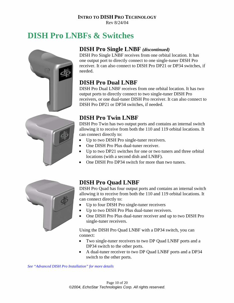
DISH Pro LNBFs & Switches DISH Pro Single LNBF (discontinued) DISH Pro Single LNBF receives from one orbital location. It has one output port to directly connect to one single-tuner DISH Pro receiver. It can also connect to DISH Pro DP21 or DP34 switches, if needed. DISH Pro Dual LNBF DISH Pro Dual LNBF receives from one orbital location. It has two output ports to directly connect to two single-tuner DISH Pro receivers, or one dual-tuner DISH Pro receiver. It can also connect to DISH Pro DP21 or DP34 switches, if needed. DISH Pro Twin LNBF DISH Pro Twin has two output ports and contains an internal switch allowing it to receive from both the 110 and 119 orbital locations. It can connect directly to: • Up to two DISH Pro single-tuner receivers. • One DISH Pro Plus dual-tuner receiver. • Up to two DP21 switches for one or two tuners and three orbital
locations (with a second dish and LNBF). • One DISH Pro DP34 switch for more than two tuners.
DISH Pro Quad LNBF DISH Pro Quad has four output ports and contains an internal switch allowing it to receive from both the 110 and 119 orbital locations. It can connect directly to: • Up to four DISH Pro single-tuner receivers • Up to two DISH Pro Plus dual-tuner receivers. • One DISH Pro Plus dual-tuner receiver and up to two DISH Pro
single-tuner receivers. Using the DISH Pro Quad LNBF with a DP34 switch, you can connect: • Two single-tuner receivers to two DP Quad LNBF ports and a
DP34 switch to the other ports. • A dual-tuner receiver to two DP Quad LNBF ports and a DP34
switch to the other ports.
See “Advanced DISH Pro Installation” for more details

INTRO TO DISH PRO TECHNOLOGY Rev 8/24/04
Page 11 of 20 ©2004, EchoStar Technologies Corp. All rights reserved.
DISH Pro Quad Connectivity Guide After running Check Switch
Direct-Connect to 4 Single-Tuner Receivers
Direct-Connect to 2 Single-Tuner Receivers and 1 Dual-Tuner Receiver
110 & 119 110 & 119
OR
Single-Tuner Receiver Dual-Tuner Receiver DP34 Switch* (can “trunk” up to two more DP34 Switches after one is connected to the DP LNBF)
DP34Default states occur before the check switch is run.
DISH Pro Quad Default States Port Port Port Port 1 2 3 4
119 110 119 110
*Also applies to DP Plus 44 Switch
INTRO TO DISH PRO TECHNOLOGY Rev 8/24/04
Page 12 of 20 ©2004, EchoStar Technologies Corp. All rights reserved.
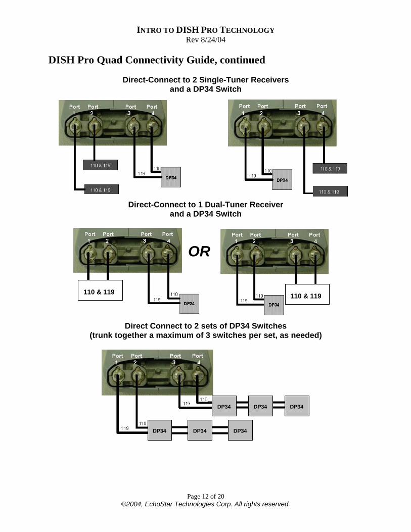
DISH Pro Quad Connectivity Guide, continued
Direct-Connect to 2 Single-Tuner Receivers and a DP34 Switch
Direct-Connect to 1 Dual-Tuner Receiver and a DP34 Switch
Direct Connect to 2 sets of DP34 Switches (trunk together a maximum of 3 switches per set, as needed)
DP34 DP34 DP34
DP34DP34 DP34
110 & 119 110 & 119
OR
INTRO TO DISH PRO TECHNOLOGY Rev 8/24/04
Page 13 of 20 ©2004, EchoStar Technologies Corp. All rights reserved.
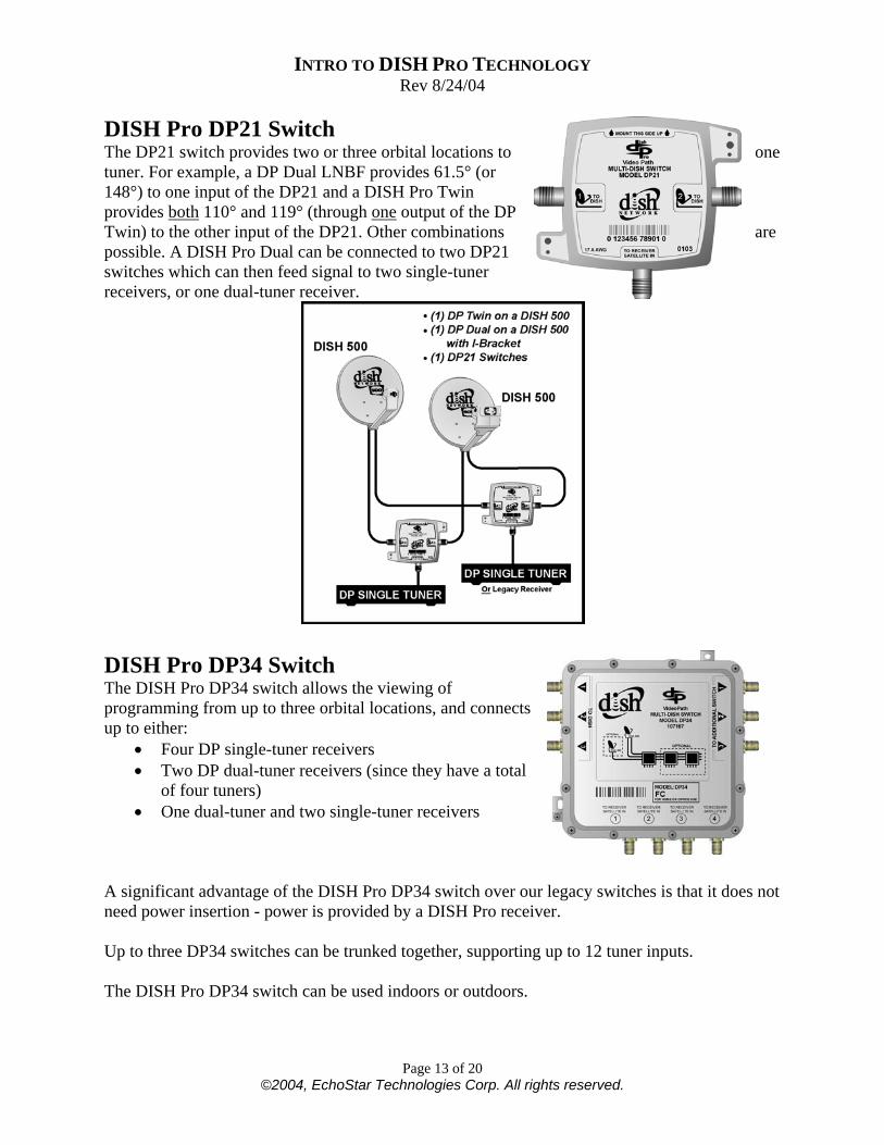
DISH Pro DP21 Switch The DP21 switch provides two or three orbital locations to one tuner. For example, a DP Dual LNBF provides 61.5° (or 148°) to one input of the DP21 and a DISH Pro Twin provides both 110° and 119° (through one output of the DP Twin) to the other input of the DP21. Other combinations are possible. A DISH Pro Dual can be connected to two DP21 switches which can then feed signal to two single-tuner receivers, or one dual-tuner receiver.
DISH Pro DP34 Switch The DISH Pro DP34 switch allows the viewing of programming from up to three orbital locations, and connects up to either:
• Four DP single-tuner receivers • Two DP dual-tuner receivers (since they have a total
of four tuners) • One dual-tuner and two single-tuner receivers
A significant advantage of the DISH Pro DP34 switch over our legacy switches is that it does not need power insertion - power is provided by a DISH Pro receiver. Up to three DP34 switches can be trunked together, supporting up to 12 tuner inputs. The DISH Pro DP34 switch can be used indoors or outdoors.
INTRO TO DISH PRO TECHNOLOGY Rev 8/24/04
Page 14 of 20 ©2004, EchoStar Technologies Corp. All rights reserved.
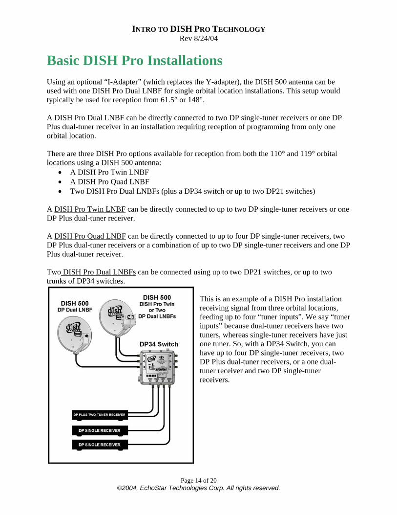
Basic DISH Pro Installations Using an optional “I-Adapter” (which replaces the Y-adapter), the DISH 500 antenna can be used with one DISH Pro Dual LNBF for single orbital location installations. This setup would typically be used for reception from 61.5° or 148°. A DISH Pro Dual LNBF can be directly connected to two DP single-tuner receivers or one DP Plus dual-tuner receiver in an installation requiring reception of programming from only one orbital location. There are three DISH Pro options available for reception from both the 110° and 119° orbital locations using a DISH 500 antenna:
• A DISH Pro Twin LNBF • A DISH Pro Quad LNBF • Two DISH Pro Dual LNBFs (plus a DP34 switch or up to two DP21 switches)
A DISH Pro Twin LNBF can be directly connected to up to two DP single-tuner receivers or one DP Plus dual-tuner receiver. A DISH Pro Quad LNBF can be directly connected to up to four DP single-tuner receivers, two DP Plus dual-tuner receivers or a combination of up to two DP single-tuner receivers and one DP Plus dual-tuner receiver. Two DISH Pro Dual LNBFs can be connected using up to two DP21 switches, or up to two trunks of DP34 switches.
This is an example of a DISH Pro installation receiving signal from three orbital locations, feeding up to four “tuner inputs”. We say “tuner inputs” because dual-tuner receivers have two tuners, whereas single-tuner receivers have just one tuner. So, with a DP34 Switch, you can have up to four DP single-tuner receivers, two DP Plus dual-tuner receivers, or a one dual-tuner receiver and two DP single-tuner receivers.
INTRO TO DISH PRO TECHNOLOGY Rev 8/24/04
Page 15 of 20 ©2004, EchoStar Technologies Corp. All rights reserved.
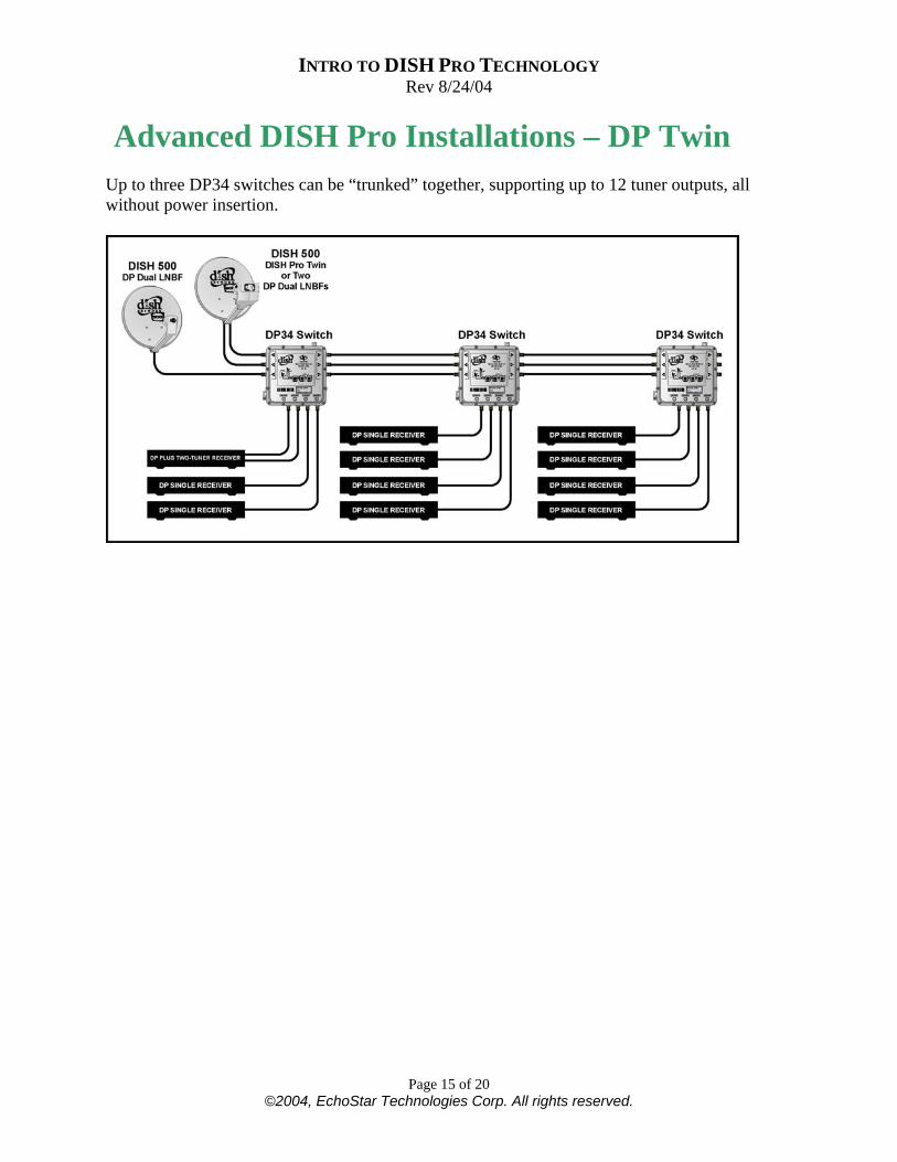
Advanced DISH Pro Installations – DP Twin Up to three DP34 switches can be “trunked” together, supporting up to 12 tuner outputs, all without power insertion.
INTRO TO DISH PRO TECHNOLOGY Rev 8/24/04
Page 16 of 20 ©2004, EchoStar Technologies Corp. All rights reserved.
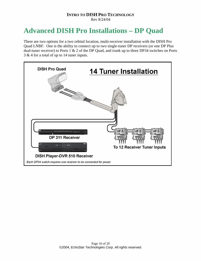
Advanced DISH Pro Installations – DP Quad There are two options for a two orbital location, multi-receiver installation with the DISH Pro Quad LNBF. One is the ability to connect up to two single-tuner DP receivers (or one DP Plus dual-tuner receiver) to Ports 1 & 2 of the DP Quad, and trunk up to three DP34 switches on Ports 3 & 4 for a total of up to 14 tuner inputs.
INTRO TO DISH PRO TECHNOLOGY Rev 8/24/04
Page 17 of 20 ©2004, EchoStar Technologies Corp. All rights reserved.
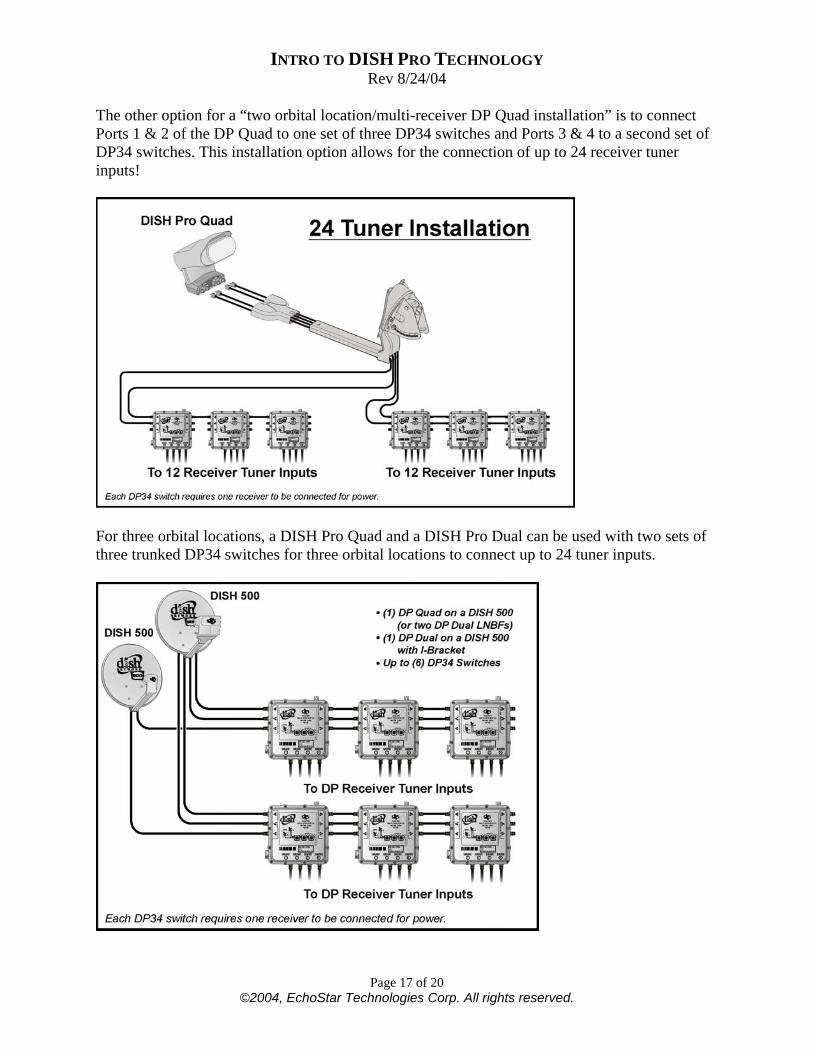
The other option for a “two orbital location/multi-receiver DP Quad installation” is to connect Ports 1 & 2 of the DP Quad to one set of three DP34 switches and Ports 3 & 4 to a second set of DP34 switches. This installation option allows for the connection of up to 24 receiver tuner inputs!
For three orbital locations, a DISH Pro Quad and a DISH Pro Dual can be used with two sets of three trunked DP34 switches for three orbital locations to connect up to 24 tuner inputs.
INTRO TO DISH PRO TECHNOLOGY Rev 8/24/04
Page 18 of 20 ©2004, EchoStar Technologies Corp. All rights reserved.
Advanced DISH Pro Installations – SuperDISH All forms of SuperDISH use three LNBs/LNBFs (all of which are either DP or at least bandstacked) that connect to a DP34 switch. LNBs/LNBFs: All SuperDISH configurations use at least one standard LNBF, which is either a DP Single or more likely a DP Dual. Switch: The DP34 switch is used the same way as in any other installation. The Check Switch results for a SuperDISH installation may show some ports as “Feed” instead of “Sgl” or “Dual” – this is a normal response, because those are the “bandstacked” (non-DISH Pro) LNBs.
INTRO TO DISH PRO TECHNOLOGY Rev 8/24/04
Page 19 of 20 ©2004, EchoStar Technologies Corp. All rights reserved.
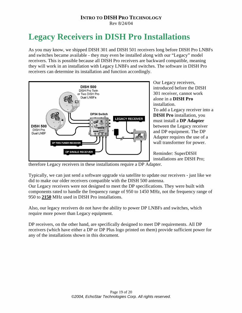
Legacy Receivers in DISH Pro Installations As you may know, we shipped DISH 301 and DISH 501 receivers long before DISH Pro LNBFs and switches became available - they may even be installed along with our “Legacy” model receivers. This is possible because all DISH Pro receivers are backward compatible, meaning they will work in an installation with Legacy LNBFs and switches. The software in DISH Pro receivers can determine its installation and function accordingly.
Our Legacy receivers, introduced before the DISH 301 receiver, cannot work alone in a DISH Pro installation. To add a Legacy receiver into a DISH Pro installation, you must install a DP Adapter between the Legacy receiver and DP equipment. The DP Adapter requires the use of a wall transformer for power. Reminder: SuperDISH installations are DISH Pro;
therefore Legacy receivers in these installations require a DP Adapter. Typically, we can just send a software upgrade via satellite to update our receivers - just like we did to make our older receivers compatible with the DISH 500 antenna. Our Legacy receivers were not designed to meet the DP specifications. They were built with components rated to handle the frequency range of 950 to 1450 MHz, not the frequency range of 950 to 2150 MHz used in DISH Pro installations. Also, our legacy receivers do not have the ability to power DP LNBFs and switches, which require more power than Legacy equipment. DP receivers, on the other hand, are specifically designed to meet DP requirements. All DP receivers (which have either a DP or DP Plus logo printed on them) provide sufficient power for any of the installations shown in this document.
INTRO TO DISH PRO TECHNOLOGY Rev 8/24/04
Page 20 of 20 ©2004, EchoStar Technologies Corp. All rights reserved.
Summary DISH Pro technology not only includes great receivers and new LNBFs and switches, but also offers many installation advantages: • Simplified installations and greater reliability by requiring fewer cables. • Longer cable runs - up to 200 feet. • Installations are easier to troubleshoot, with diagnostics using two-way communication. All are great advantages that save time and money, but remember there are special requirements. All installation materials used must meet the 950 to 2150 MHz specification and pass the DiSEqC 22 KHz tone. These include: • RG6 cable - no RG59 allowed! • Diplexers • Line amps • Barrel connectors • Wall plates • Ground blocks • Surge protectors A list of approved DP installation accessories can be found on the retailer website (retailer.echostar.com).