Introduction to CMMN
22
INTRODUCTION TO CMMN EXAMPLES FROM HEALTHCARE Nico Herzberg August 28, 2015
-
Upload
nico-herzberg -
Category
Technology
-
view
1.065 -
download
1
Transcript of Introduction to CMMN

INTRODUCTION TO CMMN EXAMPLES FROM HEALTHCARE
Nico Herzberg
August 28, 2015

Structured/Unstructured Processes
Nico Herzberg 2 Introduc=on to CMMN
Strukturierung eines Prozesses
Strukturiert Strukturiert mit Ad-‐Hoc-‐Ausnahmen
Unstrukturiert m. vordefinierten Fragmenten
Unstrukturiert
z.B. Kunden-‐registrierung, Rechnungsstellung
z.B. Back-‐Office in Finanzdienstleistung
z.B. Seefracht, Insolvenz, TV-‐Live-‐Show
z.B. Feuerwehr-‐einsatz?, Forschung?
Vorhersehbar Wiederholbar
Variabel Einzigar=g
Strukturierte Daten Daten/Dokumente/Unstrukturierte Daten Unstrukturierte Daten
Steuerung Unterstützung
BPMN BPMN CMMN/BPMN (CMMN?)
Quelle: Sandy Kemsley, Case Management and BPM (White Paper)
Mo=va=on
• Transferability and adop=on of a clinical pathway is not supported
• Required flexibility cannot be expressed in BPMN models
Nico Herzberg 3 Introduc=on to CMMN
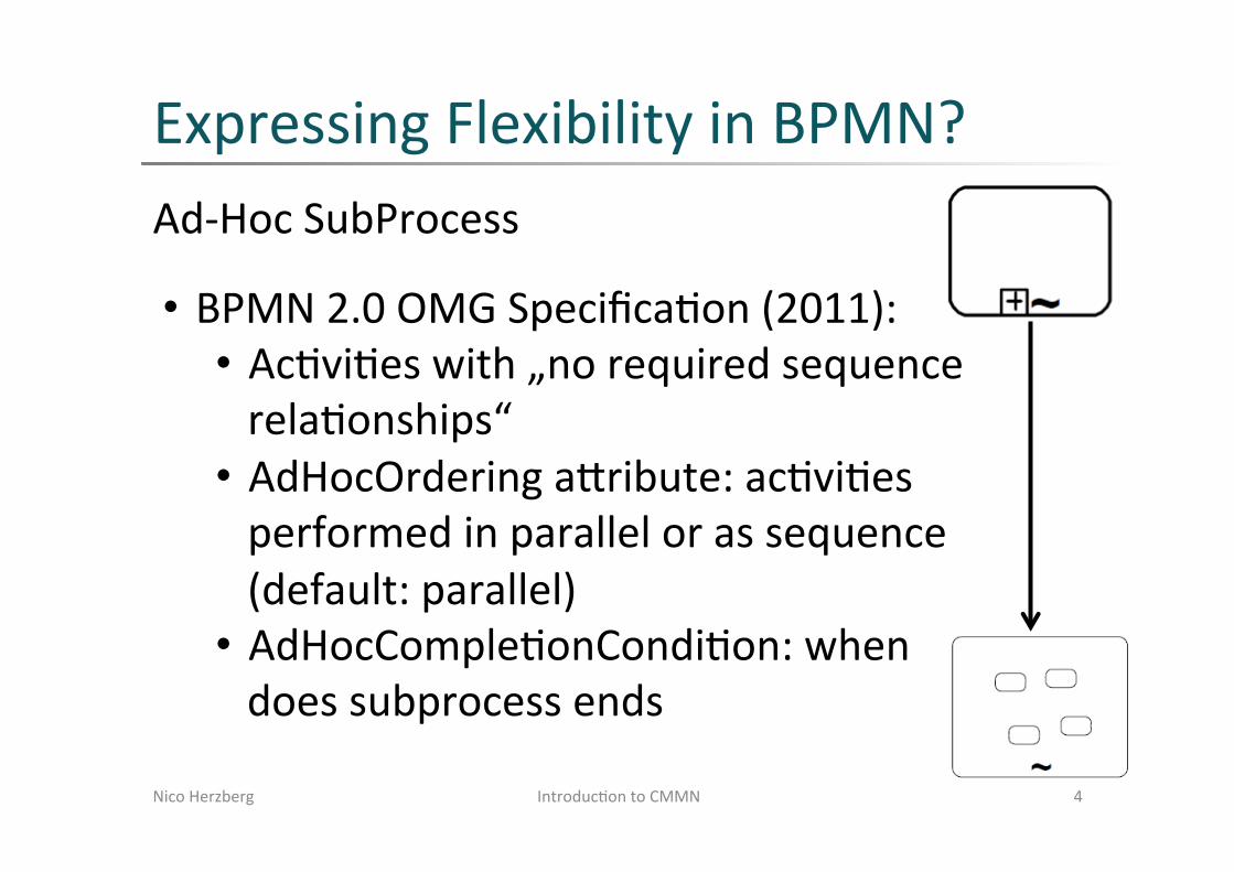
Expressing Flexibility in BPMN? Ad-‐Hoc SubProcess
Nico Herzberg 4 Introduc=on to CMMN
• BPMN 2.0 OMG Specifica=on (2011): • Ac=vi=es with „no required sequence rela=onships“ • AdHocOrdering agribute: ac=vi=es performed in parallel or as sequence (default: parallel) • AdHocComple=onCondi=on: when does subprocess ends
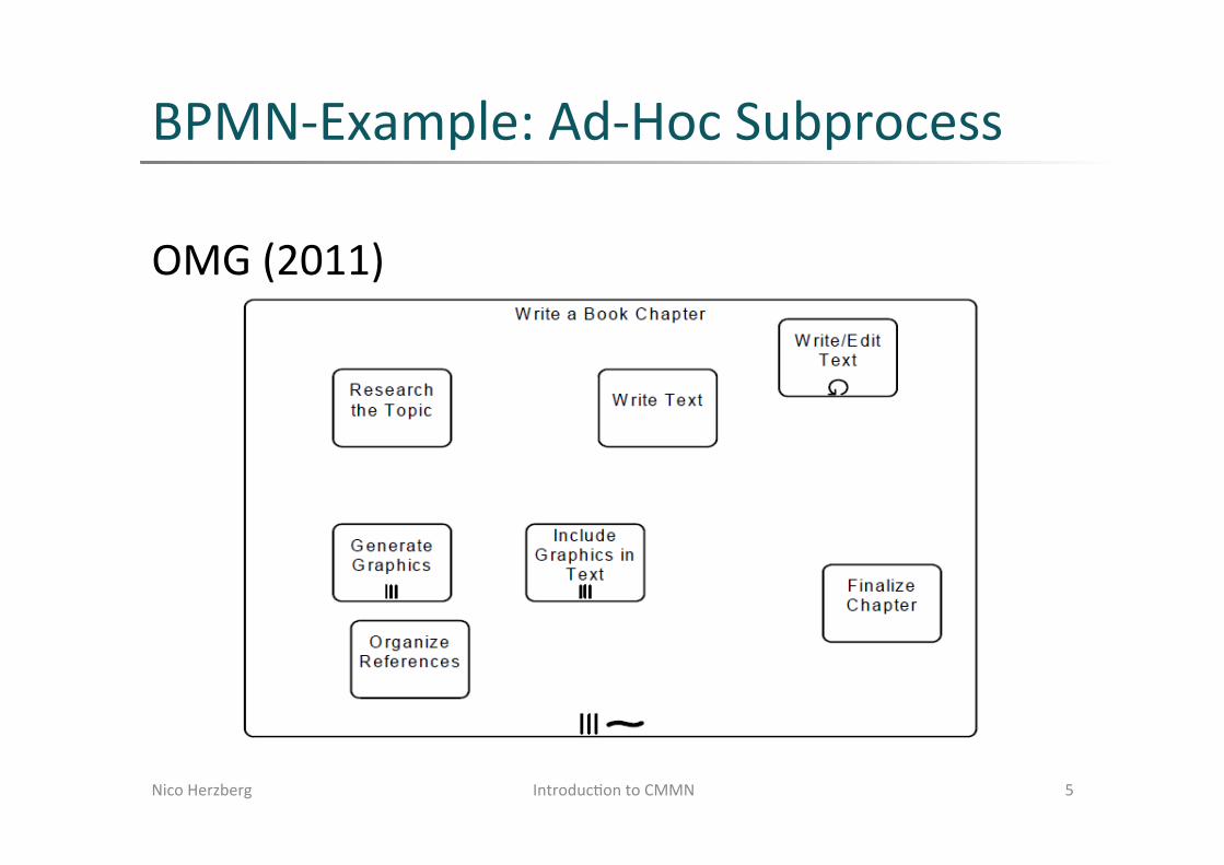
BPMN-‐Example: Ad-‐Hoc Subprocess
OMG (2011)
Nico Herzberg 5 Introduc=on to CMMN

Scenario (I/II)
Nico Herzberg 6 Introduc=on to CMMN
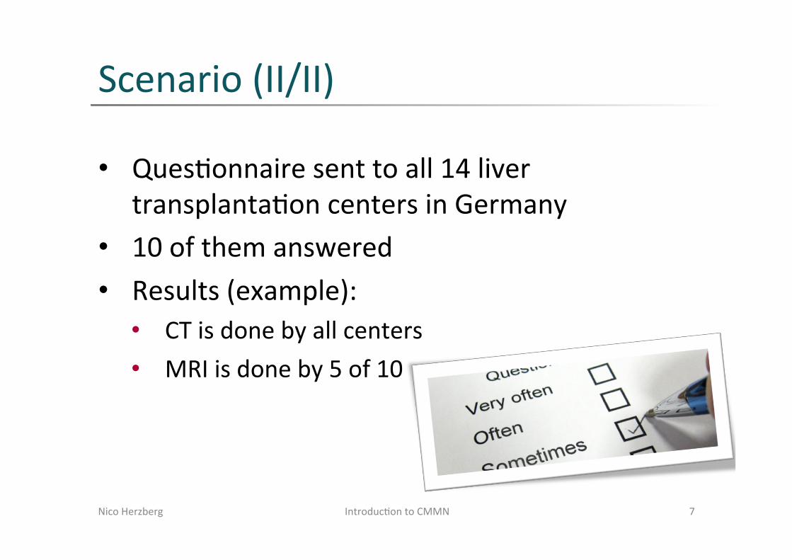
Scenario (II/II)
Nico Herzberg 7 Introduc=on to CMMN
• Ques=onnaire sent to all 14 liver transplanta=on centers in Germany
• 10 of them answered • Results (example): • CT is done by all centers • MRI is done by 5 of 10
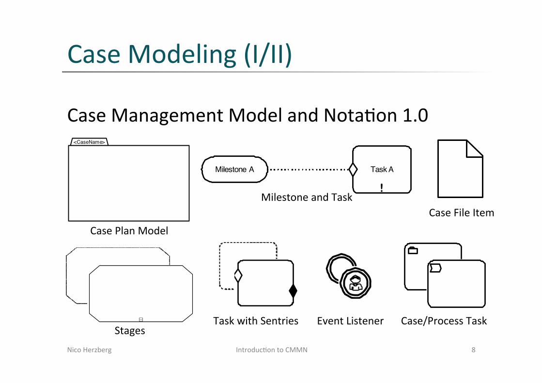
Case Modeling (I/II)
Case Management Model and Nota=on 1.0
Nico Herzberg 8 Introduc=on to CMMN
Case Management Model and Notation, v1.0 55
The following diagram illustrates a situation where Stage B depends on the exit criterion of Stage A.
Figure 6.34 - Using Sentry-based connector to visualize dependency between Stages
Note that the connection of the connector (i.e., onPart of the entry criterion Sentry of B) to the exit criterion Sentry of A visualizes the sentryRef of the onPart of the entry criterion Sentry of B (see 5.4.6.1).
The construct in Figure 6.35 may be considered a “Stage transition,” triggered by a particular event. Stage B is enabled via its entry criterion (depicted on its boundary), the OnPart of which may specify as standardEvent the termination of Stage A, given that it terminates based on the exit criterion (as depicted on its boundary). That exit criterion may itself has an OnPart (not depicted as connector) that refers e.g., to the creation of a document (CaseFileItem instance). So, when an instance of the document is created, Stage A terminates, and Stage B is enabled upon termination of Stage A, given that it terminates based on that document creation event.
The following diagram illustrates a situation where Task A depends on the achievement of Milestone A.
Figure 6.35 - Using the Sentry-based connector to visualize dependency between a Task and a Milestone
The following diagram illustrates a situation where Task A depends on a TimerEventListener.
Figure 6.36 - Using the Sentry-based connector to visualize dependency between a Task and a TimerEventListener
The following diagram illustrates a situation where Task A depends on a CaseFileItem.
Figure 6.37 - Using the Sentry-based connector to visualize dependency between a Task and a CaseFileItem
!
Stage A
!
Stage B
Milestone A
!
Task A
!
Task A
!
Task A
Case Management Model and Notation, v1.0 45
6 Notation
6.1 IntroductionThe following sub clauses provide an overview of the CMMN notation used for modeling the core constructs of a Case.
6.2 CaseThe CMMN notation provides for the depiction of the behavioral model elements of a Case (i.e., elements of a Case's casePlanModel). As far as modeling of information is concerned, only the information model elements (i.e., CaseFileItems) that are involved in the behavior of the Case are depicted. In other words, the CMMN notation does not provide for the visual modeling of the information model elements of the Case.
As with many other modeling languages, there are many different ways in which to model a Case using CMMN and its notation. It is left to the modeler to choose the best model to capture the essence of the situation at hand for the desired purpose.
6.3 Case Plan ModelsThe complete behavior model of a Case is captured in a casePlanModel. A casePlanModel is depicted using a “Folder” shape that consists of a rectangle with an upper left smaller rectangle attached to it. The name of the Case can be enclosed into the upper left rectangle.
Figure 6.1 - CasePlanModel Shape
The various elements of a casePlanModel are depicted within the boundary of the casePlanModel shape. Note that the casePlanModel is the outermost Stage that can be defined for a Case.
The following diagram shows an example of a Case’s casePlanModel. Although incomplete, this diagram exemplifies the basis of Case modeling using the CMMN notation.
<CaseName>
Case Management Model and Notation, v1.0 47
Figure 6.4 - Collapsed Stage and Expanded Stage Shapes
A Stage may be discretionary (i.e., used as DiscretionaryItem that is contained in a PlanningTable). A discretionary Stage has the shape of a rectangle with short dashed lines and angled corners and a marker in the form of a “+” sign in a small box at its bottom center, while a discretionary expanded Stage has the shape of a rectangle with short dashed lines and angled corners and a marker in the form of a “-” sign in a small box at its bottom center.
Figure 6.5 - Discretionary Collapsed Stage and Discretionary Expanded Stage Shapes
When a Stage is expanded, elements that are contained in it become visible.
6.6 Entry and Exit CriterionPlanItems may have associated Sentries. When a Sentry is used as an entry criterion it is depicted by a shallow “Diamond” shape.
Figure 6.6 - EntryCriterion Shape
When a Sentry is used as an exit criterion it is depicted by a solid “Diamond” shape.
!
!
Case Management Model and Notation, v1.0 49
Figure 6.10 - Task Shape
A Task may be discretionary (i.e., used as DiscretionaryItem contained in a PlanningTable). A discretionary Task is depicted by a rectangle shape with dashed lines and rounded corners.
Figure 6.11 - Discretionary Task
A Task may be associated with one or more entry criteria Sentries and one or more exit criteria Sentries.
The following example illustrates a Task with one entry criterion and one exit criterion.
Figure 6.12 - Task with one entry criterion and one exit criterion
6.8.1 Human TaskA HumanTask has two possible depictions. If the HumanTask is non-blocking (i.e., isBlocking set to “false”), it is depicted by a rectangle with rounded corners and a “Hand” symbol in the upper left corner. If the HumanTask is blocking (i.e., isBlocking set to “true”), it is depicted by a rectangle with rounded corners and a “User” symbol in the upper left corner.
Figure 6.13 - Non-blocking HumanTask Shape
52 Case Management Model and Notation, v1.0
Figure 6.22 - Alternative ProcessTask Shapes
A discretionary ProcessTask can also be depicted by a dash-lined rectangle with rounded corners with an optional “Chevron” symbol in the upper left corner, a collapsed marker and a thick border.
Figure 6.23 - Alternative Discretionary ProcessTask Shapes
6.9 MilestonesA Milestone is depicted by a rectangle shape with half-rounded ends.
Figure 6.24 - Milestone Shape
A Milestone may have zero or more entry criteria.
Figure 6.25 - Milestone with one entry criterion
6.10 EventListenersAn EventListener is depicted by a double line circle shape with an open center so that markers can be placed within it to indicate variations of an EventListener. The circle MUST be drawn with a double line.
Figure 6.26 - EventListener Shape
A TimerEventListener is depicted by double line circle shape with a “Clock” marker in the center.
Case Management Model and Notation, v1.0 53
Figure 6.27 - TimerEventListener Shape
A UserEventListener is depicted by double line circle shape with a “User” symbol marker in the center.
Figure 6.28 - UserEventListener Shape
6.11 ConnectorsCertain dependencies between elements that are shown inside expanded Stages or PlanFragments are depicted using connectors. The shape of the connector object is a dotted line. The connector MUST not have arrowheads.
Figure 6.29 - Connector Shape
One such depicted dependency is the onPart of a Sentry. For example, the following diagram illustrates a situation where the entry criteria of Task B depends on the completion of Task A.
Figure 6.30 - Sentry-based dependency between two Tasks
The other type of dependency that is visualized is the dependency between a HumanTask and DiscretionaryItems in its PlanningTable, when the HumanTask is shown with its PlanningTable expanded. These dependencies are also depicted by the same dotted line connector.
!
Task A
!
Task B
Case Plan Model
Stages
Milestone and Task
Task with Sentries Event Listener
50 Case Management Model and Notation, v1.0
Figure 6.14 - Blocking HumanTask Shape
A HumanTask may be discretionary (i.e., used as DiscretionaryItem contained in a PlanningTable). A discretionary HumanTask is depicted by a rectangle shape with dashed lines and rounded corners with the appropriate marker depending if it is blocking or not.
Figure 6.15 - Non-Blocking and Blocking Discretionary HumanTasks
6.8.2 Case TaskA CaseTask is depicted by rectangle shape with rounded corners with a “Folder” symbol in the upper left corner.
Figure 6.16 - CaseTask Shape
A CaseTask may be discretionary (i.e., used as DiscretionaryItem contained in a PlanningTable). A discretionary CaseTask is depicted by a dash lined rectangle with rounded corners with a “Folder” symbol in the upper right corner.
Figure 6.17 - Discretionary CaseTask Shape
6.8.2.1 Case Task for BPMN Compatibility Conformance
Tools implementing the BPMN Compatibility Conformance type SHOULD use this additional notation; this sub clause is optional otherwise.
A CaseTask can also be depicted by a rectangle shape with rounded corners with a “Folder” symbol in the upper left corner, a collapsed marker and a thick border.
Case Management Model and Notation, v1.0 51
Figure 6.18 - Alternative CaseTask shape
A discretionary CaseTask can also be depicted by a dash-lined rectangle with rounded corners with a “Folder” symbol in the upper left corner, a collapsed marker and a thick border.
Figure 6.19 - Alternative Discretionary CaseTask shape
6.8.3 Process TaskA ProcessTask is depicted by a rectangle shape with rounded corners with a “Chevron” symbol in the upper left corner.
Figure 6.20 - ProcessTask Shape
A ProcessTask may be discretionary (i.e., used as DiscretionaryItem contained in a PlanningTable). A discretionary ProcessTask is depicted by a dash lined rectangle with rounded corners with a “Chevron” symbol in the upper left corner.
Figure 6.21 - Discretionary ProcessTask Shape
6.8.3.1 Process Task for BPMN Compatibility Conformance
Tools implementing the BPMN Compatibility Conformance type SHOULD use this additional notation; this sub clause is optional otherwise.
A ProcessTask can also be depicted by a rectangle shape with rounded corners with an optional “Chevron” symbol in the upper left corner, a collapsed marker and a thick border.
Case/Process Task
46 Case Management Model and Notation, v1.0
Figure 6.2 - CasePlanModel Example
CMMN is declarative by nature, thus one should not read any meaning into the relative positioning of shapes.
6.4 Case File ItemsA CaseFileItem is depicted by a “Document” shape that consists of a rectangle with a broken upper right corner.
Figure 6.3 - CaseFileItem Shape
6.5 StagesA Stage is depicted by a rectangle shape with angled corners and a marker in the form of a “+” sign in a small box at its bottom center. When the Stage is expanded it is depicted by a rectangle shape with angled corners and a marker in the form of a “-” sign in a small box at its bottom center.
Treat Fracture
Examine Patient
Prescribe Medication
Prescribe Sling
Perform XRay
Perform Surgery
Prescribe Fixation
Apply Cast
Prescribe Rehabilitation
Case File Item

Case Modeling (II/II)
Nico Herzberg 9 Introduc=on to CMMN
Case Modeling (II/II)
Nico Herzberg 9 Modeling and Monitoring Variability in Hospital Treatments -‐ A Scenario using CMMN

Tooling
Nico Herzberg 10 Introduc=on to CMMN
Trisotech CMMN Modeler: hgp://cmmnwebmodeler.com/
Discussion (I/II)
• Modeling a general process valid for several hospitals • Yes, it is possible • Expressing mandatory tasks in one hospital is
difficult à expert knowledge required
• Explicit modeling of roles not supported • Role assignment to cases and human tasks • Not expressed explicitly in the model
Nico Herzberg 11 Introduc=on to CMMN

Discussion (II/II)
• Explicit modeling of loca=ons not supported • Could be expressed by structuring, e.g. stages
• How to deal with complexity? • Structuring
• How to use case plan models? • CMMN + hospital specific best prac=ces • CMMN as template à adop=on by each hospital • CMMN as inspira=on for a more concrete model
Nico Herzberg 12 Introduc=on to CMMN

Future Work
• Is CMMN the right choice for modeling clinical pathways? • How to deal with the weaknesses? • Extensions required?
• Evalua=on of CMMN in hospitals • Best prac=ces for using CMMN in healthcare
Nico Herzberg 13 Introduc=on to CMMN

Evalua=on of CMMN in hospitals Diagnose bei Verdacht auf Leberzellkrebs
Nico Herzberg 14 Introduc=on to CMMN

Evalua=on of CMMN in hospitals Diagnose bei Verdacht auf Leberzellkrebs
Nico Herzberg 15 Introduc=on to CMMN

Evalua=on of CMMN in hospitals Ambulante Nachsorge für einen Empfänger einer Leber
Nico Herzberg 16 Introduc=on to CMMN

Evalua=on of CMMN in hospitals Ambulante Nachsorge für einen Empfänger einer Leber
Nico Herzberg 17 Introduc=on to CMMN

Evalua=on of CMMN in hospitals Tägliche Visite für einen Leberlebendspender
Nico Herzberg 18 Introduc=on to CMMN

Evalua=on of CMMN in hospitals Tägliche Visite für einen Leberlebendspender
Nico Herzberg 19 Introduc=on to CMMN

Evalua=on of CMMN in hospitals Rekonvaleszenz eines Leberlebendspenders
Nico Herzberg 20 Introduc=on to CMMN
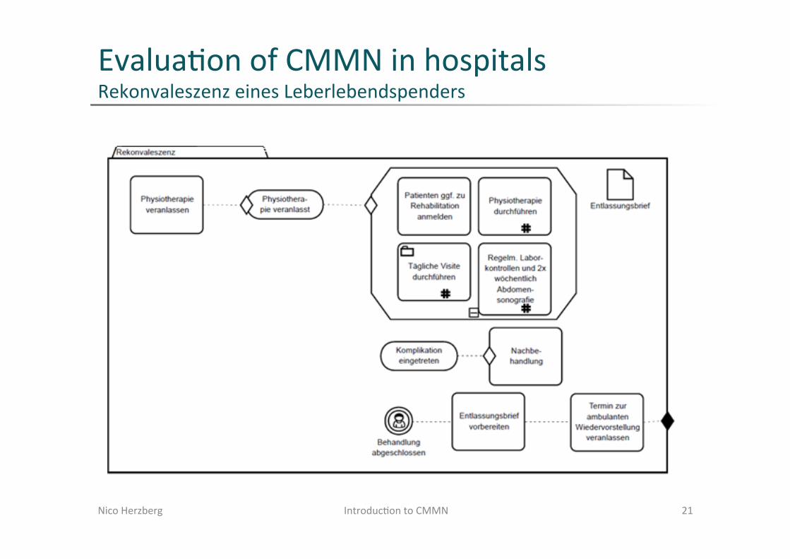
Evalua=on of CMMN in hospitals Rekonvaleszenz eines Leberlebendspenders
Nico Herzberg 21 Introduc=on to CMMN
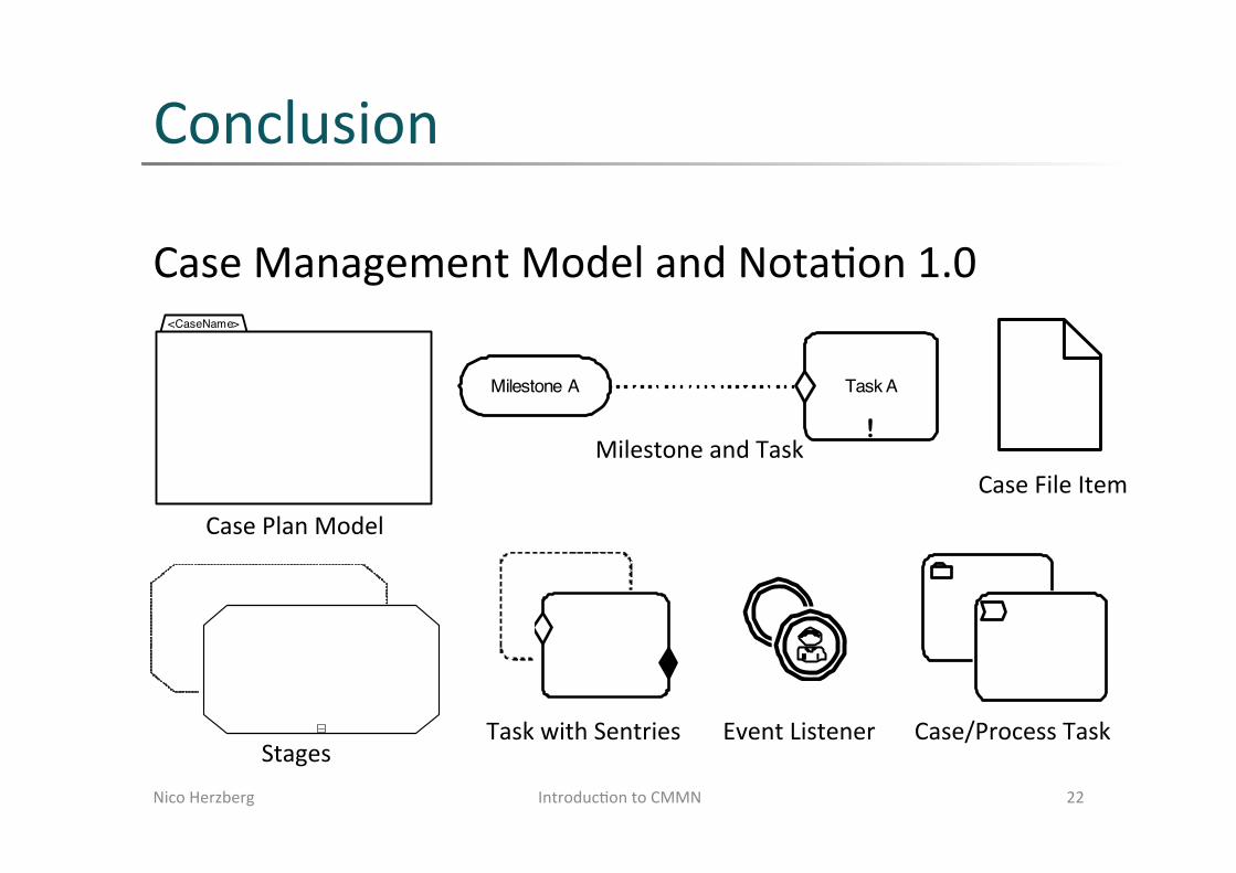
Conclusion
Case Management Model and Nota=on 1.0
Nico Herzberg 22 Introduc=on to CMMN
Case Management Model and Notation, v1.0 55
The following diagram illustrates a situation where Stage B depends on the exit criterion of Stage A.
Figure 6.34 - Using Sentry-based connector to visualize dependency between Stages
Note that the connection of the connector (i.e., onPart of the entry criterion Sentry of B) to the exit criterion Sentry of A visualizes the sentryRef of the onPart of the entry criterion Sentry of B (see 5.4.6.1).
The construct in Figure 6.35 may be considered a “Stage transition,” triggered by a particular event. Stage B is enabled via its entry criterion (depicted on its boundary), the OnPart of which may specify as standardEvent the termination of Stage A, given that it terminates based on the exit criterion (as depicted on its boundary). That exit criterion may itself has an OnPart (not depicted as connector) that refers e.g., to the creation of a document (CaseFileItem instance). So, when an instance of the document is created, Stage A terminates, and Stage B is enabled upon termination of Stage A, given that it terminates based on that document creation event.
The following diagram illustrates a situation where Task A depends on the achievement of Milestone A.
Figure 6.35 - Using the Sentry-based connector to visualize dependency between a Task and a Milestone
The following diagram illustrates a situation where Task A depends on a TimerEventListener.
Figure 6.36 - Using the Sentry-based connector to visualize dependency between a Task and a TimerEventListener
The following diagram illustrates a situation where Task A depends on a CaseFileItem.
Figure 6.37 - Using the Sentry-based connector to visualize dependency between a Task and a CaseFileItem
!
Stage A
!
Stage B
Milestone A
!
Task A
!
Task A
!
Task A
Case Management Model and Notation, v1.0 45
6 Notation
6.1 IntroductionThe following sub clauses provide an overview of the CMMN notation used for modeling the core constructs of a Case.
6.2 CaseThe CMMN notation provides for the depiction of the behavioral model elements of a Case (i.e., elements of a Case's casePlanModel). As far as modeling of information is concerned, only the information model elements (i.e., CaseFileItems) that are involved in the behavior of the Case are depicted. In other words, the CMMN notation does not provide for the visual modeling of the information model elements of the Case.
As with many other modeling languages, there are many different ways in which to model a Case using CMMN and its notation. It is left to the modeler to choose the best model to capture the essence of the situation at hand for the desired purpose.
6.3 Case Plan ModelsThe complete behavior model of a Case is captured in a casePlanModel. A casePlanModel is depicted using a “Folder” shape that consists of a rectangle with an upper left smaller rectangle attached to it. The name of the Case can be enclosed into the upper left rectangle.
Figure 6.1 - CasePlanModel Shape
The various elements of a casePlanModel are depicted within the boundary of the casePlanModel shape. Note that the casePlanModel is the outermost Stage that can be defined for a Case.
The following diagram shows an example of a Case’s casePlanModel. Although incomplete, this diagram exemplifies the basis of Case modeling using the CMMN notation.
<CaseName>
Case Management Model and Notation, v1.0 47
Figure 6.4 - Collapsed Stage and Expanded Stage Shapes
A Stage may be discretionary (i.e., used as DiscretionaryItem that is contained in a PlanningTable). A discretionary Stage has the shape of a rectangle with short dashed lines and angled corners and a marker in the form of a “+” sign in a small box at its bottom center, while a discretionary expanded Stage has the shape of a rectangle with short dashed lines and angled corners and a marker in the form of a “-” sign in a small box at its bottom center.
Figure 6.5 - Discretionary Collapsed Stage and Discretionary Expanded Stage Shapes
When a Stage is expanded, elements that are contained in it become visible.
6.6 Entry and Exit CriterionPlanItems may have associated Sentries. When a Sentry is used as an entry criterion it is depicted by a shallow “Diamond” shape.
Figure 6.6 - EntryCriterion Shape
When a Sentry is used as an exit criterion it is depicted by a solid “Diamond” shape.
!
!
Case Management Model and Notation, v1.0 47
Figure 6.4 - Collapsed Stage and Expanded Stage Shapes
A Stage may be discretionary (i.e., used as DiscretionaryItem that is contained in a PlanningTable). A discretionary Stage has the shape of a rectangle with short dashed lines and angled corners and a marker in the form of a “+” sign in a small box at its bottom center, while a discretionary expanded Stage has the shape of a rectangle with short dashed lines and angled corners and a marker in the form of a “-” sign in a small box at its bottom center.
Figure 6.5 - Discretionary Collapsed Stage and Discretionary Expanded Stage Shapes
When a Stage is expanded, elements that are contained in it become visible.
6.6 Entry and Exit CriterionPlanItems may have associated Sentries. When a Sentry is used as an entry criterion it is depicted by a shallow “Diamond” shape.
Figure 6.6 - EntryCriterion Shape
When a Sentry is used as an exit criterion it is depicted by a solid “Diamond” shape.
!
!
Case Management Model and Notation, v1.0 49
Figure 6.10 - Task Shape
A Task may be discretionary (i.e., used as DiscretionaryItem contained in a PlanningTable). A discretionary Task is depicted by a rectangle shape with dashed lines and rounded corners.
Figure 6.11 - Discretionary Task
A Task may be associated with one or more entry criteria Sentries and one or more exit criteria Sentries.
The following example illustrates a Task with one entry criterion and one exit criterion.
Figure 6.12 - Task with one entry criterion and one exit criterion
6.8.1 Human TaskA HumanTask has two possible depictions. If the HumanTask is non-blocking (i.e., isBlocking set to “false”), it is depicted by a rectangle with rounded corners and a “Hand” symbol in the upper left corner. If the HumanTask is blocking (i.e., isBlocking set to “true”), it is depicted by a rectangle with rounded corners and a “User” symbol in the upper left corner.
Figure 6.13 - Non-blocking HumanTask Shape
Case Management Model and Notation, v1.0 49
Figure 6.10 - Task Shape
A Task may be discretionary (i.e., used as DiscretionaryItem contained in a PlanningTable). A discretionary Task is depicted by a rectangle shape with dashed lines and rounded corners.
Figure 6.11 - Discretionary Task
A Task may be associated with one or more entry criteria Sentries and one or more exit criteria Sentries.
The following example illustrates a Task with one entry criterion and one exit criterion.
Figure 6.12 - Task with one entry criterion and one exit criterion
6.8.1 Human TaskA HumanTask has two possible depictions. If the HumanTask is non-blocking (i.e., isBlocking set to “false”), it is depicted by a rectangle with rounded corners and a “Hand” symbol in the upper left corner. If the HumanTask is blocking (i.e., isBlocking set to “true”), it is depicted by a rectangle with rounded corners and a “User” symbol in the upper left corner.
Figure 6.13 - Non-blocking HumanTask Shape
52 Case Management Model and Notation, v1.0
Figure 6.22 - Alternative ProcessTask Shapes
A discretionary ProcessTask can also be depicted by a dash-lined rectangle with rounded corners with an optional “Chevron” symbol in the upper left corner, a collapsed marker and a thick border.
Figure 6.23 - Alternative Discretionary ProcessTask Shapes
6.9 MilestonesA Milestone is depicted by a rectangle shape with half-rounded ends.
Figure 6.24 - Milestone Shape
A Milestone may have zero or more entry criteria.
Figure 6.25 - Milestone with one entry criterion
6.10 EventListenersAn EventListener is depicted by a double line circle shape with an open center so that markers can be placed within it to indicate variations of an EventListener. The circle MUST be drawn with a double line.
Figure 6.26 - EventListener Shape
A TimerEventListener is depicted by double line circle shape with a “Clock” marker in the center.
Case Management Model and Notation, v1.0 53
Figure 6.27 - TimerEventListener Shape
A UserEventListener is depicted by double line circle shape with a “User” symbol marker in the center.
Figure 6.28 - UserEventListener Shape
6.11 ConnectorsCertain dependencies between elements that are shown inside expanded Stages or PlanFragments are depicted using connectors. The shape of the connector object is a dotted line. The connector MUST not have arrowheads.
Figure 6.29 - Connector Shape
One such depicted dependency is the onPart of a Sentry. For example, the following diagram illustrates a situation where the entry criteria of Task B depends on the completion of Task A.
Figure 6.30 - Sentry-based dependency between two Tasks
The other type of dependency that is visualized is the dependency between a HumanTask and DiscretionaryItems in its PlanningTable, when the HumanTask is shown with its PlanningTable expanded. These dependencies are also depicted by the same dotted line connector.
!
Task A
!
Task B
Case Plan Model
Stages
Milestone and Task
Task with Sentries Event Listener
50 Case Management Model and Notation, v1.0
Figure 6.14 - Blocking HumanTask Shape
A HumanTask may be discretionary (i.e., used as DiscretionaryItem contained in a PlanningTable). A discretionary HumanTask is depicted by a rectangle shape with dashed lines and rounded corners with the appropriate marker depending if it is blocking or not.
Figure 6.15 - Non-Blocking and Blocking Discretionary HumanTasks
6.8.2 Case TaskA CaseTask is depicted by rectangle shape with rounded corners with a “Folder” symbol in the upper left corner.
Figure 6.16 - CaseTask Shape
A CaseTask may be discretionary (i.e., used as DiscretionaryItem contained in a PlanningTable). A discretionary CaseTask is depicted by a dash lined rectangle with rounded corners with a “Folder” symbol in the upper right corner.
Figure 6.17 - Discretionary CaseTask Shape
6.8.2.1 Case Task for BPMN Compatibility Conformance
Tools implementing the BPMN Compatibility Conformance type SHOULD use this additional notation; this sub clause is optional otherwise.
A CaseTask can also be depicted by a rectangle shape with rounded corners with a “Folder” symbol in the upper left corner, a collapsed marker and a thick border.
Case Management Model and Notation, v1.0 51
Figure 6.18 - Alternative CaseTask shape
A discretionary CaseTask can also be depicted by a dash-lined rectangle with rounded corners with a “Folder” symbol in the upper left corner, a collapsed marker and a thick border.
Figure 6.19 - Alternative Discretionary CaseTask shape
6.8.3 Process TaskA ProcessTask is depicted by a rectangle shape with rounded corners with a “Chevron” symbol in the upper left corner.
Figure 6.20 - ProcessTask Shape
A ProcessTask may be discretionary (i.e., used as DiscretionaryItem contained in a PlanningTable). A discretionary ProcessTask is depicted by a dash lined rectangle with rounded corners with a “Chevron” symbol in the upper left corner.
Figure 6.21 - Discretionary ProcessTask Shape
6.8.3.1 Process Task for BPMN Compatibility Conformance
Tools implementing the BPMN Compatibility Conformance type SHOULD use this additional notation; this sub clause is optional otherwise.
A ProcessTask can also be depicted by a rectangle shape with rounded corners with an optional “Chevron” symbol in the upper left corner, a collapsed marker and a thick border.
Case/Process Task
46 Case Management Model and Notation, v1.0
Figure 6.2 - CasePlanModel Example
CMMN is declarative by nature, thus one should not read any meaning into the relative positioning of shapes.
6.4 Case File ItemsA CaseFileItem is depicted by a “Document” shape that consists of a rectangle with a broken upper right corner.
Figure 6.3 - CaseFileItem Shape
6.5 StagesA Stage is depicted by a rectangle shape with angled corners and a marker in the form of a “+” sign in a small box at its bottom center. When the Stage is expanded it is depicted by a rectangle shape with angled corners and a marker in the form of a “-” sign in a small box at its bottom center.
Treat Fracture
Examine Patient
Prescribe Medication
Prescribe Sling
Perform XRay
Perform Surgery
Prescribe Fixation
Apply Cast
Prescribe Rehabilitation
Case File Item