RED ROCKET RED ROCKET FLY HIGH, RED ROCKET RED ROCKET PUT MONEY IN MY POCKET YEAH!

INTRODUCTION
While many experimenters are working to make large rocket motors to lift heavy rockets to high altitudes, I have taken on a project to make a small motor that can be used with rockets that can be launched from small fields by the average experimenter. Since rocket motors containing 62.5 grams of propellant or less are exempt from ATF rules it was this criterion that established the primary design goal for this motor. Also to make the motor practical it had to incorporate an effective delay grain for parachute ejection. A technique was developed using O-rings to seal a delay grain at the top end closure for the motor.
Before proceeding, become familiar with the earlier work performed on the "G", "H", "I" PVC motors.
MOTOR DESCRIPTION
Motor description
The motor casing (1) is 3/4" Schedule 40 PVC water pipe. Unlike the other PVC motors, which use end caps to retain the nozzle and top end closure, the F motor uses internal retainers (2) made from 1/2" Schedule 40 PVC pipe. While I have previously recommended against the use of internal retainers, it is possible to use internal retainers for this size motor because of the inherent strength of this diameter PVC pipe. I still recommend against the use of internal retainers for any PVC motor with an ID greater that 1 inch.
The nozzle is cast from quick setting, expansive, anchoring concrete (3) like the other larger PVC motors. Two #10 SAE steel washers (4) with an ID of 7/32" are cast into the throat of the nozzle to eliminate erosion.
The propellant grain (5) is a 4-segment BATES grain. Propellant is 65/35 potassium

nitrate and sorbitol (KNSB). The propellant segments are individually cast into 1-3/8"x 3/4" casting sleeves and have a 1/4" core. The end surfaces of each grain are uninhibited.
The top end closure is a delay grain (6). The casing for the delay grain is made from1/2" plastic CPVC water pipe and filled with a slow burning mix of potassium nitrate, confectionary sugar and 5-minute epoxy adhesive. A timing hole (7) is drilled into thedelay grain to set the delay time. The delay grain is sealed to the motor casing with 5/8" x 3/32" O-rings (8) and backed by a 3/4" x 1/8 " fender washer backer plate (9) and an internal retainer. A spacer (10) cut from 1/2" PVC pipe separates the propellant grain from the delay grain. An ejection charge of black powder fills the space within the retainer (11) and sealed with tape.
The OD of the motor is 27 mm so the motor can be wrapped with tape to allow it to fit a standard 29 mm motor mount used in many rocket kits.
F70 Motor Description
Motor Weight 170 grams / 6.0 oz.
Motor Length (Typical) 190 mm / 7.5 in.
Motor OD 27 mm / 1.06 (1-1/16) in.
Casing ID 20.6 mm / 0.813 (13/16) in.
Propellant Type KN/Sorbitol (65/35)
Propellant Weight 62.5 grams / 2.2 oz.
Grain Type BATES (outside surface inhibited)
Total Grain Length 142 mm / 5.6 in.
Number of Grain Segments 4
Segment Length 35 mm / 1.375 (1-3/8) in.
Grain OD (w/o inhibitor) 19 mm / 0.75 in.
Core Diameter 6 mm / 0.25 in.
Maximum Kn 255
Nozzle Throat Diameter 5.6 mm / 0.219 (7/32) in.
Nozzle Throat Insert #10 SAE Flat Steel Washer
Nozzle Exit Diameter 14 mm / 0.563 (9/16) in.
Nozzle Expansion Ratio 6.6:1
Casing Stock Length 215 mm / 8.5 in.
DESIGN
Performance
Performance was first modeled using a home brew Excel program that computes and plots Kn, pressure and thrust based on the physical dimensions of the motor and characteristics of KNSB propellant. With a design goal of a propellant weight of
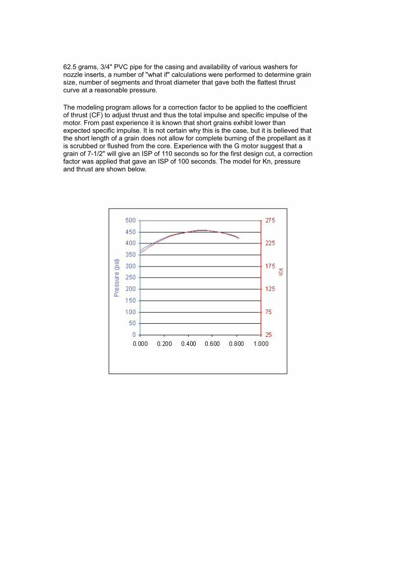
62.5 grams, 3/4" PVC pipe for the casing and availability of various washers for nozzle inserts, a number of "what if" calculations were performed to determine grain size, number of segments and throat diameter that gave both the flattest thrust curve at a reasonable pressure.
The modeling program allows for a correction factor to be applied to the coefficient of thrust (CF) to adjust thrust and thus the total impulse and specific impulse of the motor. From past experience it is known that short grains exhibit lower than expected specific impulse. It is not certain why this is the case, but it is believed thatthe short length of a grain does not allow for complete burning of the propellant as it is scrubbed or flushed from the core. Experience with the G motor suggest that a grain of 7-1/2" will give an ISP of 110 seconds so for the first design cut, a correctionfactor was applied that gave an ISP of 100 seconds. The model for Kn, pressure and thrust are shown below.

Motor Kn, chamber pressure & thrust modelcurves
Tooling was built and three full up prototype motors were constructed and tested. The first test was only to confirm the integrity of the motor casing, nozzle and top end closure. The second two tests were performed on a test stand to measure thrust with following results.
Static test #1 thrust curve

Static test #2 thrust curve
These curves were sectioned at deflection points along the curve and measured to which calibration factors were applied for time (x) and thrust (y) so that the performance of the motors could be computed. Analysis of the two curves is shown below.
Performance summary #2
Performance curve #2
There is good correlation between performances of the two motors. The burn time and total impulse werenearly equal for the two motors and peak thrust was within 5% of each other.
Compared to the model the actual thrust curves show a progressive burn and a longer than expected fall time for thrust.
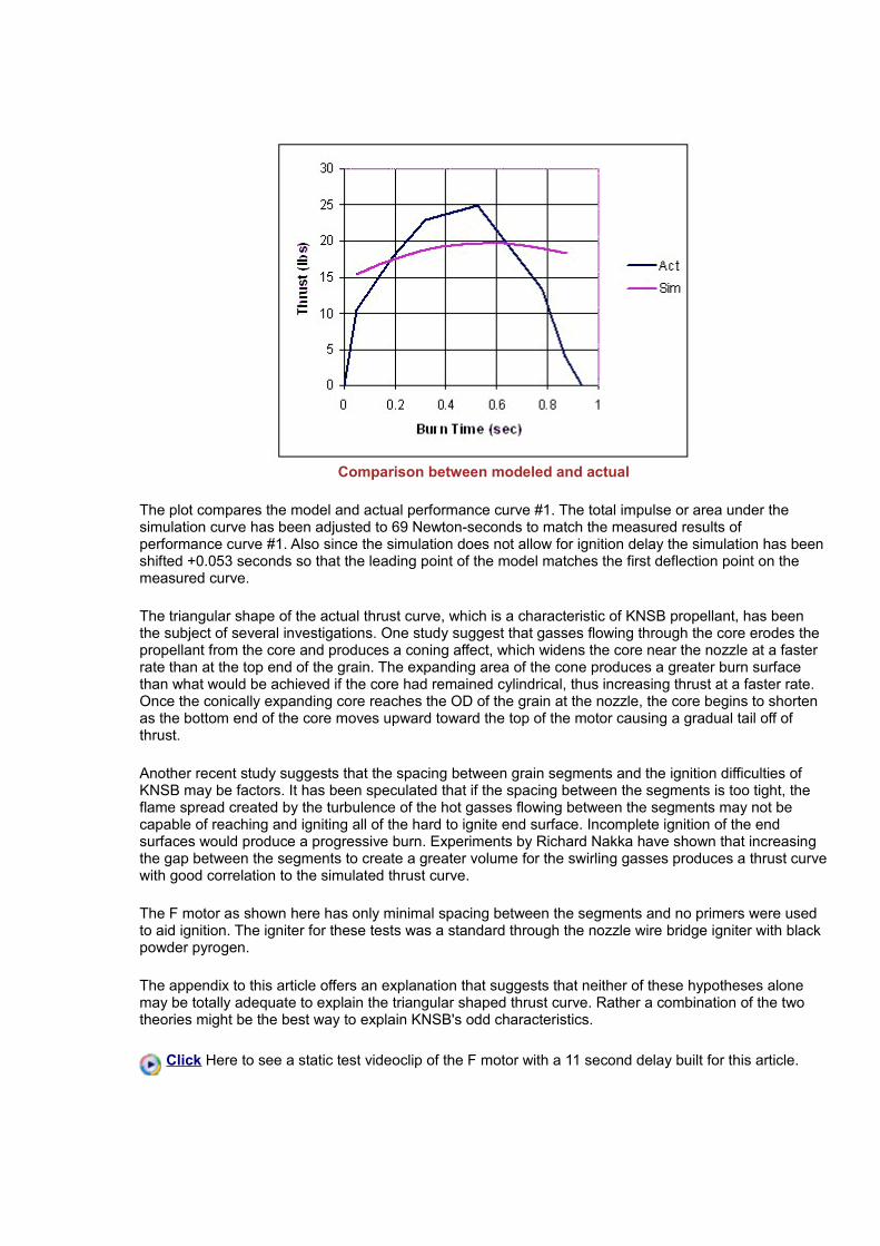
Comparison between modeled and actual
The plot compares the model and actual performance curve #1. The total impulse or area under the simulation curve has been adjusted to 69 Newton-seconds to match the measured results of performance curve #1. Also since the simulation does not allow for ignition delay the simulation has beenshifted +0.053 seconds so that the leading point of the model matches the first deflection point on the measured curve.
The triangular shape of the actual thrust curve, which is a characteristic of KNSB propellant, has been the subject of several investigations. One study suggest that gasses flowing through the core erodes the propellant from the core and produces a coning affect, which widens the core near the nozzle at a faster rate than at the top end of the grain. The expanding area of the cone produces a greater burn surface than what would be achieved if the core had remained cylindrical, thus increasing thrust at a faster rate. Once the conically expanding core reaches the OD of the grain at the nozzle, the core begins to shorten as the bottom end of the core moves upward toward the top of the motor causing a gradual tail off of thrust.
Another recent study suggests that the spacing between grain segments and the ignition difficulties of KNSB may be factors. It has been speculated that if the spacing between the segments is too tight, the flame spread created by the turbulence of the hot gasses flowing between the segments may not be capable of reaching and igniting all of the hard to ignite end surface. Incomplete ignition of the end surfaces would produce a progressive burn. Experiments by Richard Nakka have shown that increasing the gap between the segments to create a greater volume for the swirling gasses produces a thrust curvewith good correlation to the simulated thrust curve.
The F motor as shown here has only minimal spacing between the segments and no primers were used to aid ignition. The igniter for these tests was a standard through the nozzle wire bridge igniter with black powder pyrogen.
The appendix to this article offers an explanation that suggests that neither of these hypotheses alone may be totally adequate to explain the triangular shaped thrust curve. Rather a combination of the two theories might be the best way to explain KNSB's odd characteristics.
Click Here to see a static test videoclip of the F motor with a 11 second delay built for this article.

(2.4MB, AVI file)
Note: A too conservative propellant density factor was used when computing grain size based on a propellant weight. The actual propellant weights for the two prototype motors tested were 65.75 grams and 65.85 grams respectively. Since a propellant weight of 62.5 grams was the primary design goal, the grain was shortened in the final design to bring the total propellant weight closer to the design goal of 62.5 grams.
Top End Closure Delay Grain
It was felt that a slow burning delay grain for parachute ejection had to be used rather than an electronic timing devise to make this motor practical for use in small rockets. It so happens that the ID of 3/4" PVC Schedule 40 PVC pipe (13/16") is the same ID of the top end closure for the delay grain of the Aerotech Rocket 38 mm re-loadable motor cases. James Yawn describes a technique for a delay grain that uses CPVC water pipe and O-rings to make a delay grain for those motors. That technique along with a slow burning delay grain mix is used for this motor.
O-rings are classified by their ID, thickness and material. The O-rings used for this motor have an ID of 5/8", a thickness of 3/32" and are of a Buna-N material. The O-rings were purchased from allorings.com and are cataloged on their web page as -114 Buna-N O-rings selling for US$6.25 in quantity of 250. During the prototype testing of the three motors, no leakage was observed around the O-rings. This was confirmed by post mortem examination of the motor and by the fact that there was no premature ignition of the black powder ejection charge, which was part of the full-up test configuration of these motors.
The delay grain mix for the F motor is the same delay grain mix described in the construction of the G, H and I motors. The epoxy used in this mix is the same clear, 5-minute epoxy adhesive found in hardware stores, home centers and hobby shops and sold under several different brand names. The epoxy comes in squeezable plastic bottles or dual syringe dispensers. I prefer the syringe dispenser since both part A and B are dispensed at the same time making it easy to measure just a few grams. However, I have usedthe clear five-minute epoxy adhesive from the squeeze bottles with the same successful results.
This mix does not burn well in open air. If you attempt to evaluate the burn characteristics of this mix in open air you will be very disappointed. It does not ignite easily and burns with a thick crust that peels andself extinguishes. However, inside a casing ignited by the pressure, heat and flame spread of a burning propellant grain, the mix performs 100%. My guess is that this mix requires a very hot, even flame to ignite the surface as is found inside the combustion chamber of a burning motor. All three tests of this motor used this delay mix with 100% predictable results of 5, 7 and 9 second delays. This mix has been used in numerous G, H and I motor launches including a successful launch of a camera rocket using an Imotor with a 13 second delay. I have also used it with 100% success as the delay element in launches incorporating the Aerotech 38/380 RMS casing with KNSB reloads. It was used as a smoke generator in the K1000 motor used to launch Photo1. When finally recovered, this smoke grain, which was 1-1/4" in diameter and 3/4" thick, was found to have burned completely through without flaking.
Note on epoxies: I have also used 5-minute epoxy that comes in squeeze bottles that was labeled with the name of the hobby shop from which it was purchased. The bottles had a small label on the back saying it was distributed by Bob Smith Industries, CA. I suspect that the hobby shop can buy from this distributor and have their store name branded on the bottles.The Devcon and the hobby shop brands as well as another hobby brand I have all say they contain "epoxy resins" and "mercaptan amines". I suspect that there is only a few manufactures of this epoxy and they all have similar formulations. It is eventually distributed and sold under different brand names. Another thing to remember is that this is an adhesive which may be different from the fiberglassing epoxies used for marine and other structural applications.If you cannot locate the Devcon brand, go to a local hobby shop and buy a hobby brand of 5-minute epoxy adhesive that comes in clear plastic squeeze bottles. Look for the following on the label:
1. It must be an adhesive. 2. It must say epoxy 3. It must say 5-minute or some other indication that it is 5-minute quick curing.

4. It must be clear. 5. It must mix in equal portions A and B. 6. Warning or caution labels says "contains epoxy resin" and/or "mercaptan or polymercaptan amines or polyamines". Or check the MSDS on
the company's website.
If there are any doubts and before flying a rocket with a delay grain made from a questionable epoxy, do a few static tests.
Summary
1. The motor described herein will perform with the equivalent of an 81% F motor. Because the propellant weight of the prototype test motors was greater than the design goal, there has been acorrection to the final design to reduce the propellant weight to 62.5 grams. Even still, based upon an average specific impulse of 106 seconds the motor will produce a total impulse of 65 Ns with average thrust of 69.5 N for a rating of F70. This motor has enough energy to loft a 12 oz (without motor), 2" rocket to nearly 1300 feet and a lightly built, minimal diameter rocket to over 2600 feet.
2. It has been observed that this small motor exhibits the same triangular thrust curve characteristics found in the larger KNSB motors.
3. The motor can be built with a reliable delay grain to simplify rocket construction and recovery.
TOOLING
Tools make for easy and consistent building. The tools for the F motor are nearly identical in concept to the tools needed for the other PVC motors. These tools include a nozzle mold, nozzle bushing, divergence-cutting tool, casting stands and a casting sleeve-cutting guide.
Tools for F motor
Nozzle Mold
The nozzle mold is the most difficult of the tools to make because it requires that a center post be locatedexactly in the center and parallel to the central axis of a 3/4" wood dowel. The easiest way to make the nozzle mold would be with a lathe. However, for those of us without a lathe we must either use hand tools and skill or improvise a way to locate the center post.

One technique is to make a bushing to guide a drill bit into the center of a wood dowel. Such a bushing can be made using 6 each 3/4" x 1/8" fender washers, a 5/32" drill bit, CA glue or epoxy and a flat board. Start by drilling a number of 5/32" holes into the flat board. Drill the holes as accurately perpendicular to the board's surface as you can, given the tools at hand. Remove the drill bit from the drill and insert the shank end of the drill bit into one of the holes. Using a carpenter's square or drafting triangle, measure the perpendicularity of the drill bit to the board's surface along two planes, which are at right angles. Repeat until the most perpendicular hole is located.
Using the most perpendicular of the holes, insert the drill bit and stack 1 washer over the drill bit. Apply a drop of CA glue or epoxy on the top surface of the washer and stack another washer on top being carefulnot to glue the washer to the drill bit or the board. Be sure the washers are tight together. Repeat until all washers are stacked and glued together. When the glue has set, remove the washers.
Concentrically align and glue this stack of washers onto the end surface of a 3/4" dowel. Eyeball alignment should be adequate since the dowel and washers have the same diameter. Use the factory cutend of the dowel or make sure the end surface of the dowel is perfectly square to the dowel. Drill down through the stack of washers with a 5/32" drill bit into the dowel to a depth of 1/2" inch. Remove the washers and observe that the drilled hole is exactly in the center of the dowel. If necessary repeat this procedure by cutting the dowel below the hole and re-drilling the hole until the desired results are achieved.
Making the nozzle mold
Insert a 3" piece of 5/32" brass tubing into the hole. Roll the dowel across a flat surface and observe the movement of the tubing. If the tubing appears to move back and forth relative to the dowel, the hole is off center and a new hole will have to be drilled. If the tubing appears to be centered, but wobbles only slightly carefully bend the soft tubing until it no longer appears to wobble. Once the tubing is set parallel and centered to the axis of the dowel, use a drop of thin CA glue to secure the tubing in place.
Carve a 5/16" chamfer around the edge of the dowel to form the cone that will mold the nozzle converge.Waterproof this area with clear polyurethane or thin CA glue.
Fill the brass tubing with epoxy or some other filler to give it rigidity. Cut the wood dowel to a 10" length.
Final fitting of the nozzle mold to the PVC pipe will occur when the nozzle is cast.

Nozzle mold
Nozzle Bushing
The nozzle bushing is made from a 2-1/4" length of 7/32" brass tube into which is inserted a 2-1/2" lengthof 3/16" brass tubing. The 2 pieces of tubing are soldered together so that the ends of the 2 tubes are evenly aligned at one end.
Nozzle bushing
Divergence Cutter
The divergence cutter is different from those made for the other PVC motors. The divergence cutter for this motor is a right triangle cut from 1/16" hobby plywood with one angle of 15o and the long side of the triangle at least 1-1/2" in length. The long side of the triangle is epoxied lengthwise onto a 3" length of 3/16" brass tubing so that the tip of the 15o angle lies 1/8" from one end of the tubing. Seal the plywood from moisture with CA glue or polyurethane.
Divergence cutter
Sleeve-cutting Guide
Instead of rolling individual segment casting sleeves, individual sleeves are cut from one long tube. The sleeve-cutting guide is a means of accurately cutting the individual sleeves. Cut a 1-3/8" length of 3/4"

PVC pipe. Both ends of the guide should be cut as perfectly square to the pipe as possible. Glue one endof the pipe to a wood base. Remove glue fillets that may formed around the ID of the pipe.
Sleeve cutting guide
Casting Stand, Support Tube and Coring Tool
Four sets of casting tools are made so that one complete grain can be cast from a single melt. Start with the casting stand. Drill a 1/4" hole into the center of 2" x 2" squares of 1/4" plywood. Cut the support ringsfrom PVC end caps or couplers. Glue the support rings to the plywood so that the 1/4" hole is directly in the center of the support ring. Glue legs to the underside of the plywood squares so that the point of the coring tool can pass completely through the plywood base.
Coring tools are fashioned from 5" lengths of 1/4" wood dowel carved to a point on one end. Seal the wood coring tools from moisture with CA glue or polyurethane.
Support tubes are cut from 1" lengths of 3 /4" PVC pipe. These tubes are cut lengthwise into 2 halves so they fit around the casting sleeve in a clamshell fashion. Fit the support tube to the support ring by enclosing a casting sleeve within the 2 halves of a support tube and wrapping masking tape around one end of the support tube until the support tube/casting sleeve assembly fits snug within the support ring. Cut through the tape along the edge of the support tube halves to remove the casting sleeve. Mark each half of the support tube to make matching sets. (This operation can be performed at the time of casting the first grain and only needs to be performed once since casting sleeves tend to be very consistent.)
Casting tube, support guides and coring tool
Note: There are not too many glue types that are effective with PVC. PVC cement is meant to adhere

PVC to PVC in a shear configuration. Hobby epoxies are not very effective. Polyurethane adhesives are good, but they take a long time to set and they foam at the glue joint. There is a two-part, quick setting methacrylate adhesive sold under the trade name of Plastic Welder which has excellent adhesion to PVC, other plastics and materials, but it is expensive and has a shelf life once opened. For tool making where PVC has to be glued to another surface I recommend thin hobby CA glue (Instant Glue) and baking soda. For example, when gluing the PVC support rings to the plywood, lightly dust the plywood with baking soda. Once the support ring is positioned apply a drop or two of CA glue. The baking soda acts as an accelerant and filler and bonds the PVC to the plywood instantaneously and almost permanently.
CONSTRUCTION
Casing and Nozzle
Start with the casing. Three quarter (3/4") PVC pipe has a large variation in wall thickness from one pipe sample to another making for large variations in the ID. Variations of more than 1/32" have been measured. This does not sound like a big difference, but when working with small parts that need to fit into one another, tolerance build up can be a problem. To avoid this problem you will need to be selectiveof the PVC pipe used to make these motors. A good gauge for determining this is the rolled paper tube that will be the casting sleeves. If it is possible to be selective when buying your pipe, insert a casting sleeve tube into the pipe and select only pipe in which there is enough space between the tubing and thepipe to allow the tube to wobble freely. Do not select pipe in which the casting tube has a snug fit.
As a result of differences in the ID between the pipe samples, the nozzle mold has to be individually fittedto the pipe being used for the casing. To make this adjustment, wrap the nozzle mold with masking tape at two places. One location just behind the chamfer and another place about 6" down from the top. The nozzle mold should fit snug and without wobble inside the pipe. The masking tape can be added to or removed to accommodate the differences between pipe samples.
Masking tape on nozzle mold
Cut an 8-1/2" length of 3/4" PVC pipe. Rough the inside surface of one end of the pipe with sand paper toa depth of 1-1/2". For the retainer, cut a 1-1/2" length of 1/2" PVC pipe. Cut a 1/8" wide wedge from the wall of the 1/2" pipe lengthwise so it can be squeezed to fit the ID of the casing. Place a mark 1/4" from one end of this retainer stock. Clean and apply PVC cement to the first 1/4" of the retainer stock and sanded end of the casing. Q-Tips make good applicators for this operation. Insert the retainer into the casing to the depth of the 1/4" mark. Allow the cement to cure and trim the retainer stock to the end surface of the casing. Keep the left over retainer stock for the retainer at the top end of the motor.
Paint the inside surface of the casing and retainer with a flat acrylic or latex house paint to a depth of 1-1/2". Allow the paint to dry over night.

Avid F70 Motor builder Keith provided this tip: Once the nozzle retaining ring is installed, don't bother abrading or priming the inner surface. Instead, replace the water you normally use when mixing the cement with acrylic fortifier, found at any hardware store. It may also be called concrete bonding adhesive or concrete primer. Specifically, I use 7:3 cement to acrylic fortifier by weight. This will increasethe adhesion of the cement and seal the nozzle just as effectively as the latex primer. As an added benefit, it will also dramatically increase the early strength of the cement. Therefore, the nozzle will be stronger after 3 days
Casing preparation
To cast the nozzle, first apply a light coating of Vaseline to the surface of the nozzle mold that will form the convergence. Insert the nozzle mold into the casing until the center post protrudes from the casing through the retainer. Slide the divergence cutter onto the center post and position the nozzle mold inside the casing so the divergence cutter just begins to touch and rest on the ID of the retainer as the nozzle mold is withdrawn from the casing. Clamp the nozzle mold in a vise and let the casing rest on the jaws. Remove the divergence cutter and stack two #10 SAE washer throat inserts over the center post. Slide the nozzle bushing over the center post and through the washers until the washers are firmly aligned by the nozzle bushing.
Preparation for nozzle casting
Mix 2 teaspoons of the quick setting concrete and hot tap water to the consistency of thick syrup. The hot

water will make the concrete set faster and it will also produce a harder concrete that is more resistant to erosion. Pour the concrete through the opening of the retainer and around the nozzle bushing. Tap the side of the motor casing to force air bubbles to rise to the surface. Clean excess concrete from the casing. Allow the concrete to set until it just begins to harden to the touch. Too soft and the divergence will slump, too hard and you will be unable to cut the divergence.
Remove the nozzle bushing. Slide the divergence cutter onto the center post and rotate to cut the divergence. As the divergence cutter cuts deeper into the nozzle the tip of the cutter will slide through theinsert washers and stop against the nozzle mold preventing the cutter from being pushed too far into the nozzle. Remove the divergence cutter and with a twisting motion remove the casing from the nozzle mold. Allow the nozzle to harden at least 3 days.
Using the divergence cutter
Casting Sleeves
Casting sleeves are cut from a paper tube made from a single rolled sheet of 8-1/2" x 11" letter paper. Roll the paper around a 3/4" wood dowel form being sure the edges are evenly aligned. Use spray adhesive to glue the rolled layers together into a solid tube. Allow the glue to dry. The rolled tube should fit snug onto the form. These tubes will be used when selecting the 3/4" PVC pipe for the casing. Discard any tubes that have a loose fit.
To cut the individual casting sleeves, clamp the base of the sleeve-cutting guide into a vise. Insert the rolled tube into the PVC pipe. Use a sharp razor to cut the individual sleeves to the length of the PVC pipe. It is recommended that the inside seam of the sleeve be sealed with cellophane or masking tape. Four sleeves, enough for a single motor can be cut from one tube.

Making the casting sleeves
Sleeve Preparation
Wrap the support tube halves around the casting sleeves. Lay a piece of wax paper over the support rings and push the support tube and casting sleeve into the support ring. The wax paper will prevent the propellant from sticking to the casting stand. Be sure the support tube and casting sleeve are tight against the base.
Apply a thin layer of axle grease to over half the length of the coring tools.
Propellant Casting
Mix an 80-gram batch of 65/35 KNSB propellant and dry mix thoroughly in a Tupperware bowl. Melt the mixture in a temperature controlled pot at 260oF., adhering to standard safety precautions described elsewhere on this website.
Note: I no longer stir the propellant as it is melting. I cover the pot with a lid and allow the mixture to melt.I only mix lightly prior to casting. I believe stirring fluffs the propellant and adds air to the mixture, which reduces its density.
Spoon the molten propellant into the casting sleeve to about 1/8" from the top. Gently tap the casting stand against a hard surface to settle the propellant. Insert the coring tool, pointed end first, through the propellant, through the wax paper and through the hole in the casting stand. Remove spillage and smooth the overflow even with the top of the casting sleeve. Center the coring tool within the sleeve.

Casting the propellant
Allow the propellant to cure for about 30 minutes then remove the coring tool. Allow the propellant to cureanother 2 hours. Remove the propellant segment from the casting stand, remove the wax paper and support tube. Store the segments in a dessicator box for another 36 hours to complete curing. Trim bumps from the end surfaces and edges of the segments so the segments can slide easily into the casing and the end surfaces fit smoothly against each other.
Delay Grains
Delay grain casings are cut from 1/2" CPVC water pipe. The length of the casing and the number of O-rings to use will depend on the desired delay time. These casings need to be cut square to the pipe so if possible use a miter box for cutting the delay grain casings.
Fill the casing with a mixture of 1 part, by weight, of clear 5-minute epoxy adhesive and 3 parts, by weight, of a mixture of confectionary sugar and potassium nitrate. First, mix a 50-gram batch of a mixtureof 70%, by weight, of finely powdered potassium nitrate (35 grams) and 30% confectionary sugar (15 grams). Mix well. Pre-measure 6 grams of the KN /sugar mix and store the rest of the batch in a tight container and store in a dessicator box for future use. Pour 2 grams of 5-minute epoxy adhesive into a paper cup. Add the 6 grams of the KN/sugar mix. This should be enough to make 3 or 4 grains. Work quickly to thoroughly mix and pack the delay casings. Lay the casings on wax paper. Pack the mix into the casing, smooth and level the top surface of the mix even with the casing. Be sure there are no gaps between the casing and the mix. Once the mix has set remove the wax paper from the bottom surface.

Preparing the delay grain
A 1/8" hole drilled into the center of the grain sets timing of the delay. The thickness of the web between the bottom of the hole and the bottom surface of grain determines the time delay.
Casing Length No. of O-rings Web Thickness Delay
3/8" 3 1/8" 5 second
3/8" 3 3/16" 7 seconds
3/8" 3 1/4" 9 seconds
1/2" 4 5/16" 11 secondsThe timing hole is a blind hole. A drill press that the can measure the depth of a hole as it is being drilled makes this operation easy. However, if all you have is a hand drill, one way to perform this operation would be to determine the depth of the hole by subtracting the desired web thickness from the length of the casing. Clamp a collar that will be used as a stop onto the 1/8" bit so that the length of the protruding bit is the value of the depth of the hole. Drill the hole to the depth of the collar.
The collar shown was purchased from a hobby shop that sells model aircraft accessories. Collars are available in different sizes. They have a setscrew so they can be fastened securely onto heavy wire or rods. They have a variety of uses including retaining wheels on axles.

Setup for drilling timing hole
Final Assembly
All components are ready for final assembly of the motor.
Preparing for final assembly of F motor
Insert the 4 grain segments into the casing so that the smooth end or bottom end of the segments mate against the top end of the adjacent segment and are all in the same direction. Cut a 1/8" spacer from 1/2"PVC pipe. Cut a wedge from the wall of the spacer so it can be squeezed to fit the casing.
Apply a light coating of plumber's silicone grease onto the ID of the casing from the spacer to the top of the casing. Do not use Vaseline or axle grease. Also apply a light coating of the grease around the outside surface of the delay grain casing being careful not to get grease on the burn surfaces. Lightly coat the 5/8" x 3/32" O-rings with grease. Slide the O-rings over the delay grain. Insert this assembly into the top end of the casing with the timing hole pointing up. Use a 3/4" dowel to push the delay grain firmly against the spacer. Lay a 3/4" x 1/8" fender washer against the delay grain.
Measure the distance from the fender washer to the top of the casing inside the casing. Subtract 1/4" from this measurement and measure the resulting distance down from the top of the casing on the outside of the casing. Place a mark on the casing at this location. The mark represents the final length of the motor so if there are any doubts as to the accuracy, mark to the short side of this measurement. You will want at least 1/4" from the fender washer to the top of the casing to secure the retainer. Measure twice and cut once. Take the thickness of the saw blade into account and at the mark cut the casing to

final length.
Clean the grease from the ID of the casing. Use the left over retainer stock from the nozzle. Clean and glue the retainer into the top of the casing so it is seated tight against the fender washer. Let the glue dry then trim the retainer stock to the end surface of the casing.
A thrust ring can be added to the motor by gluing a ring cut from 3/4" PVC coupler or end hat to the nozzle end of the motor.
The motor is now complete.
Completed F motor
APPENDIX
THRUST CURVE ANALYSIS
It was postulated earlier in this article that there were two possible reasons why the actual thrust curve is triangular shaped and differs so greatly from the ideal model.
1.The difficulty to achieve adequate ignition of the end surfaces. This can be caused by two reasons(a) The inherent hard to ignite characteristics of KNSB.(b) Too tight of spacing between segments does not allow for hot swirling gasses to reach all partsof the end surface.
2. The erosion and coning of the grain due to scrubbing and/or flushing of the propellant from the grain.
Incomplete Ignition
It can be determined from the actual performance curves for the prototype motors that the first deflection point or initial thrust for these motors was 10.4 lbs and 8.4 lbs for performance curve #1 and #2 respectively. Under ideal conditions where all surfaces ignite evenly and instantaneously, the initial thrust points for the F70 motor can be computed for various numbers of segments:

No. of Segments Initial Thrust Point
1 10
2 12
3 14
4 15As the number of segments increases so does the initial thrust. This is expected since the two end surfaces of each segment add to the burn surface and contributes to thrust. Clearly, if the measured initial thrust for the prototype motors is less than 11 lbs, there is an incomplete ignition of all surfaces.
Core Erosion
This is a condition where flowing gasses erode propellant from the core. Since the gasses are flowing fastest nearest the nozzle, the erosion produces a cone, which is widest at the nozzle and tapers toward the top of the grain. The expanding area of the cone produces a greater burn surface than would be achieved if the core had remained cylindrical, thus increasing thrust at a faster rate. Once the conically expanding core reaches the OD of the grain at the nozzle, the core begins to shorten as the bottom end of the core moves upward toward the top of the motor causing a gradual tail off of thrust.
The following plot shows the ideal thrust curve model compared against a model for an eroding core where the expansion rate near the nozzle is 1.2 times faster than at the top of the grain. The erosion model assumes that all end surfaces are fully ignited.
Comparison between ideal and erosive core thrust curves
The area under the curve or total impulse is the same for both curves and equals the total impulse of the actual curves. The curves show that there is almost no difference in the upward slope of the two curves over the first half of the curve. It appears, therefore, that erosion alone cannot account for the progressive like burn exhibited by the measured curves. However, erosion might still account for extended trail off of the thrust.

Combined Scenario
For the F70 motor it is believed that a combination of both incomplete ignition and erosion are taking place. The following plot compares the actual thrust curve to erosion models for both a 4-segmented and a 1-segmented grain. The single segment model is representative of incomplete ignition where only the core is ignited. All curves have equal total impulse.
Comparison between ideal and erosive core thrust curves for 4 & 1 segment motors
Upon ignition, the hard to ignite characteristics of KNSB propellant along with the tight spacing of the segments prevents the ignition of the end surfaces and allows only for the ignition of the core shown by the model for the single segment. This limited burn surface produces only about 2/3 of the potential initialthrust of the motor under ideal conditions. As the grain continues to burns, the end surfaces ignite and add to the total burn surface that increases thrust in a progressive manner. About half way through the burn the model for the 4-segment grain and actual curve begin to merge. When the erosion near the nozzle reaches the OD of the grain, the grain begins to shorten causing the thrust to trail off over an extended period.
Conclusion
The limited data from experiments with the F motor provide one possible model for the odd burn characteristics of KNSB propellant. Additional experiments are needed to confirm or adjust this model to achieve a full understanding of this propellant.
It should also be noted that despite the lack of a complete understanding of KNSB propellant, the rocket motor described herein is effective and reliable.
UPDATE

Kirksville High School 2016 Rocket Project -- An adventurous school project that involved building and launching rockets powered by the F70 PVC rocket motor. Congratulations to the students and teachers who participated in this bold and successful initiative. The students clearly enjoyed this exciting challenge-- the effort put into their rockets is impressive, demonstrating that learning about rockets can be fun and educational. It is experiences such as this that sow the seeds of future rocket engineers and scientists...!