Introduction of Company - Top Entitytopentity.com.my/downloads/fec.pdf · Introduction of Company...
189
FEC Cables (M) Sdn Bhd file:///E|/contents/intro.htm[10/14/2010 3:41:04 PM] Introduction of Company When there is talk of high quality electric wires and cables, the one company that comes to mind is FEC Cables (Malaysia) Sdn. Bhd. FEC is a subsidiary of Permodalan Nasional Berhad and was formerly known as Furukawa Electric Cables (M) Sdn. Bhd. Having established its Shah Alam plant in 1967 on a 7- acre site at the Shah Alam Industrial Estate, Furukawa has come a long way. The technical collaboration with our Japanese counterpart, Furukawa Japan, has brought about an amazing success for us. In terms of quality, we have climbed the ladders of product manufacturing, steadily and successfully, pushing FEC towards the pinnacle of excellence. Putting our customers’ demands and needs as our number one priority, we opened our second plant in 1995, on a 27-acre freehold land site in Bukit Raja Industrial area, Klang. In our quest for excellence, we equip the plant with the latest technological aids for the manufacture of a wide range of low and medium voltage cables. The certification of the ISO 9001 for both plants only proves that we do not compromise on quality and customer satisfaction. Our dedicated and hard- working employees are the backbone of our success. This was greatly helped by the state-of-the-art technology equipment which has led us towards excellence. Moving towards a new century, we pledge to continually strive towards progressive and dynamic growth as FEC Cables continues its efforts in contributing to the development Malaysia. FEC CABLES (M) SDN. BHD. Sales Office : Persiaran Raja Muda, 40000 Shah Alam, Selangor Darul Ehsan Malaysia. Tel : 6 03 - 5519 1110 (Hotline) Fax : 6 03 - 5519 1296 / 5513 8688 © 2008 FEC CABLES (M) SDN BHD. All Rights Reserved Home About Us Product Range Quality Assurance Manufacturing Process Contact Us
Transcript of Introduction of Company - Top Entitytopentity.com.my/downloads/fec.pdf · Introduction of Company...

FEC Cables (M) Sdn Bhd
file:///E|/contents/intro.htm[10/14/2010 3:41:04 PM]
Introduction of Company
When there is talk of high quality electric wires and cables, the one company that comes to mind is FEC Cables (Malaysia) Sdn. Bhd. FEC is a subsidiary ofPermodalan Nasional Berhad and was formerly known as Furukawa Electric Cables (M) Sdn. Bhd. Having established its Shah Alam plant in 1967 on a 7-acre site at the Shah Alam Industrial Estate, Furukawa has come a long way.
The technical collaboration with our Japanese counterpart, Furukawa Japan, has brought about an amazing success for us. In terms of quality, we haveclimbed the ladders of product manufacturing, steadily and successfully, pushing FEC towards the pinnacle of excellence.
Putting our customers’ demands and needs as our number one priority, we opened our second plant in 1995, on a 27-acre freehold land site in Bukit RajaIndustrial area, Klang. In our quest for excellence, we equip the plant with the latest technological aids for the manufacture of a wide range of low andmedium voltage cables.
The certification of the ISO 9001 for both plants only proves that we do not compromise on quality and customer satisfaction. Our dedicated and hard-working employees are the backbone of our success. This was greatly helped by the state-of-the-art technology equipment which has led us towardsexcellence.
Moving towards a new century, we pledge to continually strive towards progressive and dynamic growth as FEC Cables continues its efforts in contributingto the development Malaysia.
FEC CABLES (M) SDN. BHD.
Sales Office : Persiaran Raja Muda, 40000 Shah Alam, Selangor Darul Ehsan Malaysia.
Tel : 6 03 - 5519 1110 (Hotline) Fax : 6 03 - 5519 1296 / 5513 8688
© 2008 FEC CABLES (M) SDN BHD. All Rights Reserved
Home About Us Product Range Quality Assurance Manufacturing Process Contact Us

FEC Cables (M) Sdn. Bhd.
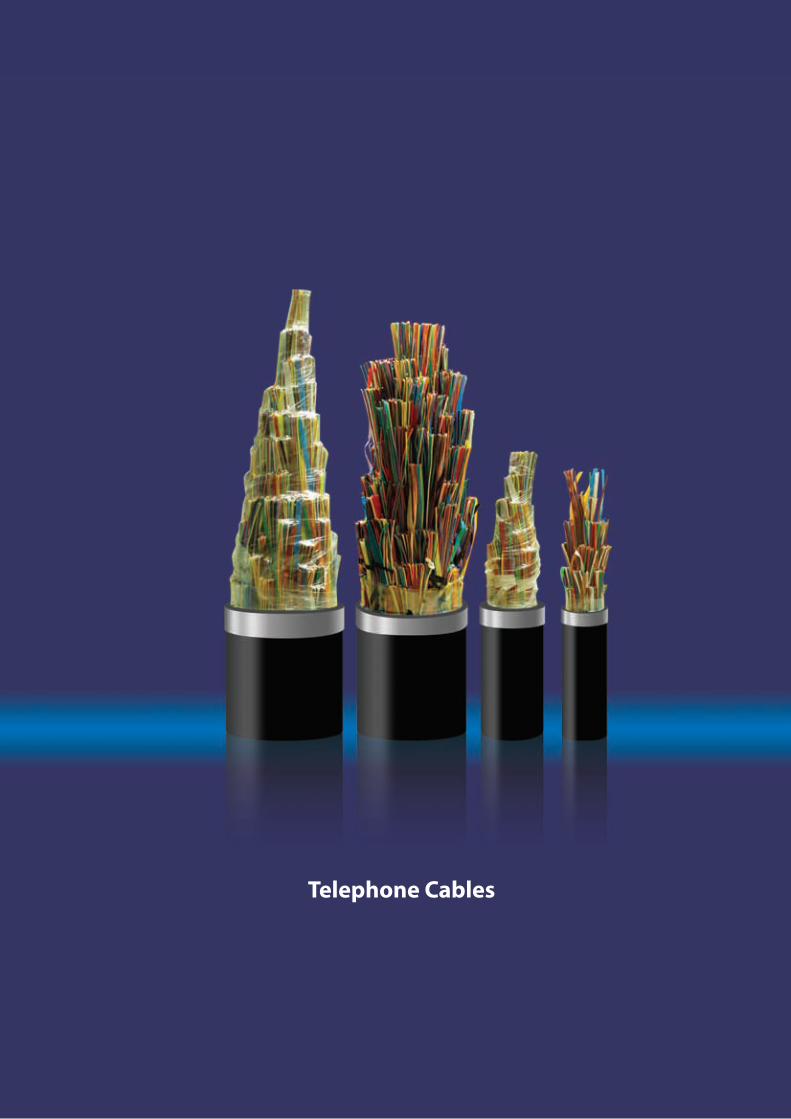
Telephone Cables

CORPORATEHISTORY
INTRODUCTION OF
COMPANYWhen there is talk of high quality electric wires and cables, the one company that comes to mind is FEC Cables (Malaysia) Sdn. Bhd. FEC is a subsidiary of Permodalan Nasional Berhad and was formerly known as Furukawa Electric Cables (M) Sdn. Bhd. Having established its Shah Alam plant in 1967 on a 7-acre site at the Shah Alam Industrial Estate, Furukawa has come a long way.
The technical collaboration with our Japanese counterpart, Furukawa Japan, has brought about an amazing success for us. In terms of quality, we have climbed the ladders of product manufacturing, steadily and successfully, pushing FEC towards the pinnacle of excellence. Putting our customers’ demands and needs as our number one priority, we opened our second plant in 1995, on a 27-acre freehold land site in Bukit Raja Industrial area, Klang. In our quest for excellence, we equip the plant with the latest technological aids for the manufacture of a wide range of low and medium voltage cables.
The certification of the ISO 9001 for both plants only proves that we do not compromise on quality and customer satisfaction. Our dedicated and hard-working employees are the backbone of our success. This was greatly helped by the state-of-the-art technology equipment which has led us towards excellence.
Moving towards a new century, we pledge to continually strive towards progressive and dynamic growth as FEC Cables continues its efforts in contributing to the development of Malaysia.
FEC Cables (M) Sdn. Bhd. was first established in 1967 and was previously known as Furukawa Electric Cables (M) Sdn. Bhd. In all the years until 2003, the company had been under the management and control of Furukawa Electric Co. Ltd. of Japan.
In 2003, the company was renamed FEC Cables (M) Sdn. Bhd. following the acquisition of its major equity stake by Permodalan Nasional Berhad, Malaysia’s government-owned premier multi-billion dollar investment institution.
The Company had started a technical collaboration from world renowned cable manufacturer, The Furukawa Electric Co. Ltd Japan (Furukawa Japan).
FEC Cables has benefited enormously from the technical collaboration and the subsequent technology transfer with Furukawa Japan. FEC Cables inherited from Furukawa Japan not only its advanced technology and technical know-how but also the disciplines of producing quality products using material conforming to the international standards of manufacturing cables.
Today FEC Cables plays a prominent role as a forerunner in the cable industry.
FEC Cables has been actively involved in serving various industrial sectors, namely the power, telecommunications, construction as well as the oil and gas sectors.
Telephone Cables

Cable Size Nom. Sheath Thickness
(mm)Approx. Overall Diameter
(mm)Approx. Cable Weight
(kg/km)No. of pairsNom. Conductor Diameter
(mm)
200400600800
100012001400160020002400
0.40
2.12.22.32.42.52.82.82.93.03.1
22.529.534.539.543.547.550.554.059.565.5
7001,2901,8602,4303,0003,5904,1404,7105,8206,940
200400600800
100012001400
0.50
2.22.32.52.82.93.03.0
26.535.542.548.554.058.062.0
1,0301,9202,8103,7004,5805,4406,290
200400600800
1000
0.63
2.32.52.93.03.1
32.544.053.561.067.5
1,5602,9504,3605,7207,070
FEC Cables (M) Sdn. Bhd.
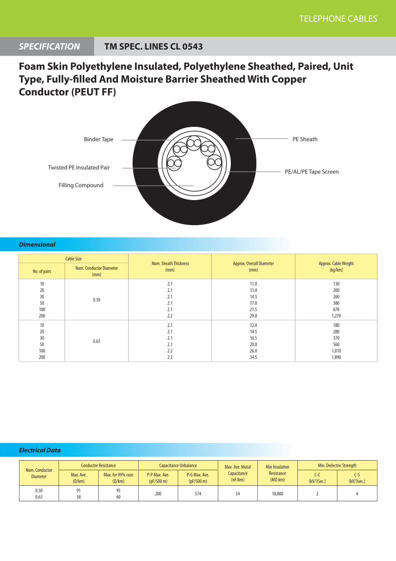
SPECIFICATION
Dimensional Dimensional
Nom. Conductor Diameter
Conductor Resistance Capacitance Unbalance Max. Ave. Mutal Capacitance
(nF/km)
Min Insulation Resistance(MΩ.km)
Min. Dielectric Strength
Max. Ave.(Ω/km)
Max. for 99% case(Ω/km)
P-P Max. Ave.(pF/500 m)
P-G Max. Ave.(pF/500 m)
C-C(kV/3Sec.)
C-S(kV/3sec.)
0.400.500.63
1439158
1509660
200 574 54 10,000 0.6 4
Binder Tape
Twisted PE Insulated Pair
PE Sheath
PE/AL/PE Tape Screen
Electrical Data
TM SPEC. LINES CL 0522
Foam Skin Polyethylene Insulated, Polyethylene Sheathed, Paired, Unit Type, Air-core And Moisture Barrier Sheathed With Copper Conductor (PEUT)
Cable Size Nom. Sheath Thickness
(mm)Approx. Overall Diameter
(mm)Approx. Cable Weight
(kg/km)No. of pairsNom. Conductor Diameter
(mm)
10203050
100200
0.50
2.12.12.12.12.12.2
11.013.014.517.021.529.0
130200260380670
1,270
10203050
100200
0.63
2.12.12.12.12.22.3
12.014.516.520.026.034.5
180280370560
1,0101,890
TELEPHONE CABLES
SPECIFICATION
Dimensional
Nom. Conductor Diameter
Conductor Resistance Capacitance Unbalance Max. Ave. Mutal Capacitance
(nF/km)
Min Insulation Resistance(MΩ.km)
Min. Dielectric Strength
Max. Ave.(Ω/km)
Max. for 99% case(Ω/km)
P-P Max. Ave.(pF/500 m)
P-G Max. Ave.(pF/500 m)
C-C(kV/3Sec.)
C-S(kV/3sec.)
0.500.63
9158
9560
200 574 54 10,000 2 4
Binder Tape
Twisted PE Insulated Pair
PE Sheath
PE/AL/PE Tape Screen
Filling Compound
Electrical Data
Foam Skin Polyethylene Insulated, Polyethylene Sheathed, Paired, Unit Type, Fully-filled And Moisture Barrier Sheathed With Copper Conductor (PEUT FF)
TM SPEC. LINES CL 0543

Cable Size Nom. Sheath Thickness
(mm)Approx. Overall Diameter
(mm)Approx. Cable Weight
(kg/km)No. of pairsNom. Conductor Diameter
(mm)
10203050
100200
0.50
2.12.12.12.12.12.2
12.013.015.017.522.029.5
190240330440760
1,350
10203050
100200
0.63
2.12.12.12.12.22.3
12.515.017.520.527.036.0
220310430600
1,0701,930
FEC Cables (M) Sdn. Bhd.
SPECIFICATION
Dimensional
Nom. Conductor Diameter
Conductor Resistance Capacitance Unbalance Max. Ave. Mutal Capacitance
(nF/km)
Min Insulation Resistance(MΩ.km)
Min. Dielectric Strength
Max. Ave.(Ω/km)
Max. for 99% case(Ω/km)
P-P Max. Ave.(pF/500 m)
P-G Max. Ave.(pF/500 m)
C-C(kV/3Sec.)
C-S(kV/3sec.)
0.500.63
9158
9560
200 574 54 10,000 2 4
Electrical Data
Twisted PE Insulated Pair
Binder Tape
PE/AL/PE Tape Screen
PE Sheath
Web
Galvanised Steel Bearer Wire
Solid Polyethylene Insulated, Polyethylene Sheathed, Paired, Unit Type, Moisture Barrier Sheathed And Integral Barrier With Copper Conductor (PEUTIB)
TM SPEC. LINES AC 0001

Factory 1Persiaran Raja Muda, 40000 Shah Alam, Selangor Darul Ehsan, Malaysia.(P.O. Box 7006, 40700 Shah Alam)Tel : 6 03 - 5519 1110 (Hotline) Fax : 6 03 - 5519 1296
Factory 2No. 16, Jalan Keluli 2, Bukit Raja Industrial Area, 41050 Klang, Selangor Darul Ehsan, Malaysia. Tel : 6 03 - 3343 5837 (Hotline) Fax : 6 03 - 3343 5843
Sales OfficePersiaran Raja Muda, 40000 Shah Alam, Selangor Darul Ehsan, MalaysiaTel : 6 03 - 5519 1110 (Hotline) Fax : 6 03 - 5519 1296 / 5513 8688Email : [email protected]
www.fec.com.my
FEC Cables (M) Sdn. Bhd.(7293-W)
Des
ign
by
Tel :
03
- 772
2 48
18

FEC Cables (M) Sdn. Bhd.
Medium Voltage Cables

CORPORATEHISTORY
INTRODUCTION OF
COMPANYWhen there is talk of high quality electric wires and cables, the one company that comes to mind is FEC Cables (Malaysia) Sdn. Bhd. FEC is a subsidiary of Permodalan Nasional Berhad and was formerly known as Furukawa Electric Cables (M) Sdn. Bhd. Having established its Shah Alam plant in 1967 on a 7-acre site at the Shah Alam Industrial Estate, Furukawa has come a long way.
The technical collaboration with our Japanese counterpart, Furukawa Japan, has brought about an amazing success for us. In terms of quality, we have climbed the ladders of product manufacturing, steadily and successfully, pushing FEC towards the pinnacle of excellence. Putting our customers’ demands and needs as our number one priority, we opened our second plant in 1995, on a 27-acre freehold land site in Bukit Raja Industrial area, Klang. In our quest for excellence, we equip the plant with the latest technological aids for the manufacture of a wide range of low and medium voltage cables.
The certification of the ISO 9001 for both plants only proves that we do not compromise on quality and customer satisfaction. Our dedicated and hard-working employees are the backbone of our success. This was greatly helped by the state-of-the-art technology equipment which has led us towards excellence.
Moving towards a new century, we pledge to continually strive towards progressive and dynamic growth as FEC Cables continues its efforts in contributing to the development of Malaysia.
FEC Cables (M) Sdn. Bhd. was first established in 1967 and was previously known as Furukawa Electric Cables (M) Sdn. Bhd. In all the years until 2003, the company had been under the management and control of Furukawa Electric Co. Ltd. of Japan.
In 2003, the company was renamed FEC Cables (M) Sdn. Bhd. following the acquisition of its major equity stake by Permodalan Nasional Berhad, Malaysia’s government-owned premier multi-billion dollar investment institution.
The Company had started a technical collaboration from world renowned cable manufacturer, The Furukawa Electric Co. Ltd Japan (Furukawa Japan).
FEC Cables has benefited enormously from the technical collaboration and the subsequent technology transfer with Furukawa Japan. FEC Cables inherited from Furukawa Japan not only its advanced technology and technical know-how but also the disciplines of producing quality products using material conforming to the international standards of manufacturing cables.
Today FEC Cables plays a prominent role as a forerunner in the cable industry.
FEC Cables has been actively involved in serving various industrial sectors, namely the power, telecommunications, construction as well as the oil and gas sectors.

Medium Voltage Cables

�
1. Non armoured cables (One core)
3.6/6 kV
6/10 kV
8.7/15 kV
12/20 kV
18/30 kV
2. Non armoured cables (Three core)
3.6/6 kV
6/10 kV
8.7/15 kV
12/20 kV
18/30 kV
3. Armoured(AWA) cables (One core)
3.6/6 kV
6/10 kV
8.7/15 kV
12/20 kV
18/30 kV
4. Armoured(SWA) cables (Three core)
3.6/6 kV
6/10 kV
8.7/15 kV
12/20 kV
18/30 kV
5. Armoured(DSTA) cables (Three core)
3.6/6 kV
6/10 kV
8.7/15 kV
12/20 kV
18/30 kV
6. Short Circuit Current, Calculation Base for
Electrical Characteristics and Correction Factors for
Continuous Current Rating
5
6
7
8
9
10
11
12
13
1�
15
16
17
18
19
20
21
22
23
2�
25
26
27
28
29
30
Table Of Contents

Nominal cross sectional area
mm² 16 25 35 50 70 95 120 150 185 240 300 400 500 630
Conductor dia. (approx.) mm 4.7 5.9 7.0 8.1 9.7 11.4 12.8 14.3 16.0 18.4 20.6 23.3 26.3 30.3
Nominal insulation thickness
mm 2.5 2.6 2.8 3.0 3.2
Nominal outer-sheath thickness
mm 1.4 1.5 1.6 1.7 1.8 1.9 2.0 2.1 2.2 2.3
Approx. overall dia. mm 17.5 18.5 20.0 21.5 23.0 25.0 26.5 28.0 30.0 32.5 35.5 38.5 42.5 47.0
Cable net. weight (approx.)
kg/kmCu 420 540 670 820 1,060 1,350 1,610 1,910 2,300 2,930 3,570 4,460 5,510 7,020
Al - 380 450 520 620 750 860 980 1,130 1,390 1,650 2,000 2,410 3,010
Nominal cross sectional area
mm² 16 25 35 50 70 95 120 150 185 240 300 400 500 630
Max. conductor resistance DC at 20°C
Ω /kmCu 1.15 0.727 0.524 0.387 0.268 0.193 0.153 0.124 0.0991 0.0754 0.0601 0.0470 0.0366 0.0283
Al - 1.20 0.868 0.641 0.443 0.320 0.253 0.206 0.164 0.125 0.100 0.0778 0.0605 0.0469
Max. conductor resistance 50Hz at 90°C
Ω /kmCu 1.47 0.927 0.668 0.494 0.342 0.247 0.196 0.159 0.128 0.0983 0.0794 0.0635 0.0512 0.0418
Al - 1.54 1.11 0.822 0.568 0.411 0.325 0.265 0.211 0.161 0.130 0.102 0.0800 0.0633
Capacitance µF/km Cu 0.21 0.24 0.28 0.31 0.35 0.40 0.43 0.47 0.52 0.56 0.57 0.60 0.62 0.71
Reactance at 50Hz Ω /km Cu 0.134 0.125 0.119 0.114 0.108 0.104 0.100 0.0973 0.0946 0.0920 0.0904 0.0883 0.0868 0.0849
Current rating In air at 40°C
ACu 105 135 165 200 250 305 355 410 470 560 645 750 865 1,000
Al - 105 130 155 195 240 280 320 365 435 505 590 690 815
Current rating In the ground at 25°C
ACu 110 145 170 205 250 300 340 380 430 495 560 635 720 810
Al - 110 135 160 195 235 265 300 340 390 445 505 580 660
Short circuit current for 1 sec.
kACu 2.41 3.72 5.18 7.36 10.2 13.8 17.4 21.8 26.8 34.7 43.4 57.7 72.1 90.8
Al - 2.48 3.45 4.89 6.80 9.19 11.5 14.4 17.7 22.9 28.6 38.1 47.6 59.8
MEDIUM VOLTAGE CABLES
5
Dimensional
MEDIUM VOLTAGE IEC 60502-2SPECIFICATION
Electrical Data
Copper And Aluminium Conductor XLPE Insulated, Copper Tape Screened, PVC Sheathed
3.6/6 (Max. 7.2) kV
1 Core
PVC Outer Sheath Binder Tape Metalic Screen Insulation Screen XLPE Insulation
Conductor Screen
Copper/Aluminium
Nominal cross sectional area
mm² 16 25 35 50 70 95 120 150 185 240 300 400 500 630
Conductor dia. (approx.)
mm 4.7 5.9 7.0 8.1 9.7 11.4 12.8 14.3 16.0 18.4 20.6 23.3 26.3 30.3
Nominal insulation thickness
mm 3.4
Nominal outer-sheath thickness
mm 1.5 1.6 1.7 1.8 1.9 2.0 2.1 2.2 2.3
Approx. overall dia. mm 19.5 20.5 22.0 23.0 25.0 27.0 28.5 30.0 32.0 34.5 36.5 39.5 42.5 47.5
Cable net. weight (approx.)
kg/kmCu 490 600 740 880 1,140 1,430 1,710 2,000 2,400 3,030 3,640 4,510 5,540 7,050
Al - 440 520 580 710 830 950 1,070 1,240 1,490 1,720 2,050 2,440 3,040
Nominal cross sectional area
mm² 16 25 35 50 70 95 120 150 185 240 300 400 500 630
Max. conductor resistance DC at 20°C
Ω /kmCu 1.15 0.727 0.524 0.387 0.268 0.193 0.153 0.124 0.0991 0.0754 0.0601 0.0470 0.0366 0.0283
Al - 1.20 0.868 0.641 0.443 0.320 0.253 0.206 0.164 0.125 0.100 0.0778 0.0605 0.0469
Max. conductor resis-tance 50Hz at 90°C
Ω /kmCu 1.47 0.927 0.668 0.494 0.342 0.247 0.196 0.159 0.128 0.0981 0.0793 0.0634 0.0511 0.0417
Al - 1.54 1.11 0.822 0.568 0.411 0.325 0.265 0.211 0.161 0.130 0.102 0.0800 0.0633
Capacitance µF/km Cu 0.17 0.19 0.22 0.24 0.27 0.31 0.33 0.36 0.40 0.44 0.48 0.53 0.59 0.68
Reactance at 50Hz Ω /km Cu 0.142 0.132 0.126 0.120 0.114 0.109 0.106 0.102 0.0994 0.0958 0.0927 0.0900 0.0876 0.0856
Current rating In air at 40°C
ACu 105 140 170 205 255 310 360 415 475 565 645 750 865 1,000
Al - 110 130 160 200 245 280 320 370 440 505 590 690 815
Current rating In the ground at 25°C
ACu 110 145 170 205 250 300 340 380 430 500 560 635 720 810
Al - 110 135 160 195 235 265 300 340 390 445 505 580 660
Short circuit current for 1 sec.
kACu 2.41 3.72 5.18 7.36 10.2 13.8 17.4 21.8 26.8 34.7 43.4 57.7 72.1 90.8
Al - 2.48 3.45 4.89 6.80 9.19 11.5 14.4 17.7 22.9 28.6 38.1 47.6 59.8
FEC Cables (M) Sdn. Bhd.
6
MEDIUM VOLTAGE IEC 60502-2SPECIFICATION
Dimensional
Electrical Data
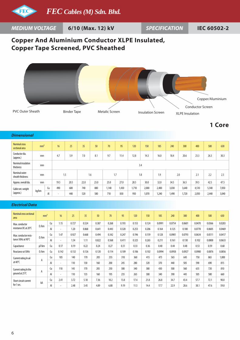
Copper And Aluminium Conductor XLPE Insulated, Copper Tape Screened, PVC Sheathed
6/10 (Max. 12) kV
1 Core
PVC Outer Sheath Binder Tape Metalic Screen Insulation Screen XLPE Insulation
Conductor Screen
Copper/Aluminium

Nominal cross sectional area
mm² 16 25 35 50 70 95 120 150 185 240 300 400 500 630
Conductor dia. (approx.)
mm - 5.9 7.0 8.1 9.7 11.4 12.8 14.3 16.0 18.4 20.6 23.3 26.3 30.3
Nominal insulation thickness
mm 4.5
Nominal outer-sheath thickness
mm - 1.6 1.7 1.8 1.9 2.0 2.1 2.2 2.3 2.4
Approx. overall dia. mm - 23.0 24.5 25.5 27.5 29.0 31.0 32.5 34.0 36.5 39.0 42.0 45.0 50.0
Cable net. weight (approx.)
kg/kmCu - 700 840 990 1,240 1,550 1,840 2,140 2,550 3,170 3,810 4,690 5,730 7,160
Al - 540 620 690 810 950 1,080 1,210 1,380 1,630 1,890 2,230 2,630 3,280
Nominal cross sectional area
mm² 16 25 35 50 70 95 120 150 185 240 300 400 500 630
Max. conductor resistance DC at 20°C
Ω /kmCu - 0.727 0.524 0.387 0.268 0.193 0.153 0.124 0.0991 0.0754 0.0601 0.0470 0.0366 0.0283
Al - 1.20 0.868 0.641 0.443 0.320 0.253 0.206 0.164 0.125 0.100 0.0778 0.0605 0.0469
Max. conductor resis-tance 50Hz at 90°C
Ω /kmCu - 0.927 0.668 0.494 0.342 0.247 0.196 0.159 0.128 0.0979 0.0790 0.0630 0.0507 0.0413
Al - 1.54 1.11 0.822 0.568 0.411 0.325 0.265 0.211 0.161 0.130 0.102 0.0798 0.0631
Capacitance µF/km Cu - 0.16 0.18 0.20 0.22 0.25 0.27 0.29 0.31 0.35 0.38 0.42 0.46 0.53
Reactance at 50Hz Ω /km Cu - 0.142 0.136 0.130 0.122 0.117 0.113 0.110 0.106 0.102 0.0986 0.0955 0.0926 0.0901
Current rating In air at 40°C
ACu - 140 175 210 260 320 365 420 480 570 655 760 875 1,010
Al - 110 135 160 200 245 285 325 375 445 510 595 695 815
Current rating In the ground at 25°C
ACu - 145 170 205 250 300 340 380 430 500 560 640 720 815
Al - 110 135 160 195 235 265 300 340 390 445 505 580 660
Short circuit current for 1 sec.
kACu - 3.72 5.18 7.36 10.2 13.8 17.4 21.8 26.8 34.7 43.4 57.7 72.1 90.8
Al - 2.48 3.45 4.89 6.80 9.19 11.5 14.4 17.7 22.9 28.6 38.1 47.6 59.8
MEDIUM VOLTAGE CABLES
7
Dimensional
MEDIUM VOLTAGE IEC 60502-2SPECIFICATION
Electrical Data
Copper And Aluminium Conductor XLPE Insulated, Copper Tape Screened, PVC Sheathed
8.7/15 (Max. 17.5) kV
1 Core
PVC Outer Sheath Binder Tape Metalic Screen Insulation Screen XLPE Insulation
Conductor Screen
Copper/Aluminium
Nominal cross sectional area
mm² 16 25 35 50 70 95 120 150 185 240 300 400 500 630
Conductor dia. (approx.)
mm - - 7.0 8.1 9.7 11.4 12.8 14.3 16.0 18.4 20.6 23.3 26.3 30.3
Nominal insulation thickness
mm 5.5
Nominal outer-sheath thickness
mm - - 1.7 1.8 1.9 2.0 2.1 2.2 2.3 2.4 2.5
Approx. overall dia. mm - - 26.0 27.5 29.5 31.0 32.5 34.5 36.0 38.5 41.0 44.0 47.5 52.0
Cable net. weight (approx.)
kg/kmCu - - 920 1,080 1,340 1,660 1,930 2,250 2,650 3,300 3,940 4,830 5,900 7,450
Al - - 700 790 910 1,060 1,180 1,320 1,490 1,760 2,020 2,370 2,810 3,450
Nominal cross sectional area
mm² 16 25 35 50 70 95 120 150 185 240 300 400 500 630
Max. conductor resistance DC at 20°C
Ω /kmCu - - 0.524 0.387 0.268 0.193 0.153 0.124 0.0991 0.0754 0.0601 0.0470 0.0366 0.0283
Al - - 0.868 0.641 0.443 0.320 0.253 0.206 0.164 0.125 0.100 0.0778 0.0605 0.0469
Max. conductor resistance 50Hz at 90°C
Ω /kmCu - - 0.668 0.494 0.342 0.247 0.196 0.159 0.128 0.0978 0.0788 0.0629 0.0505 0.0410
Al - - 1.11 0.822 0.568 0.411 0.325 0.265 0.211 0.161 0.129 0.101 0.0797 0.0629
Capacitance µF/km Cu - - 0.16 0.17 0.19 0.21 0.23 0.25 0.27 0.30 0.32 0.35 0.39 0.44
Reactance at 50Hz Ω /km Cu - - 0.141 0.135 0.128 0.122 0.117 0.114 0.110 0.105 0.102 0.0988 0.0956 0.0928
Current rating In air at 40°C
ACu - - 175 210 265 320 370 420 485 575 660 760 880 1,010
Al - - 135 165 205 250 285 325 375 445 510 595 695 815
Current rating In the ground at 25°C
ACu - - 170 205 250 300 340 380 430 500 565 640 725 815
Al - - 135 160 195 235 265 300 340 390 445 505 575 660
Short circuit current for 1 sec.
kACu - - 5.18 7.36 10.2 13.8 17.4 21.8 26.8 34.7 43.4 57.7 72.1 90.8
Al - - 3.45 4.89 6.80 9.19 11.5 14.4 17.7 22.9 28.6 38.1 47.6 59.8
FEC Cables (M) Sdn. Bhd.
8
MEDIUM VOLTAGE IEC 60502-2SPECIFICATION
Dimensional
Electrical Data
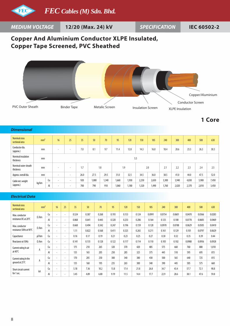
Copper And Aluminium Conductor XLPE Insulated, Copper Tape Screened, PVC Sheathed
12/20 (Max. 24) kV
1 Core
PVC Outer Sheath Binder Tape Metalic Screen Insulation Screen XLPE Insulation
Conductor Screen
Copper/Aluminium

Nominal cross sectional area
mm² 16 25 35 50 70 95 120 150 185 240 300 400 500 630
Conductor dia. (approx.)
mm - - - 8.1 9.7 11.4 12.8 14.3 16.0 18.4 20.6 23.3 26.3 30.3
Nominal insulation thickness
mm 8.0
Nominal outer-sheath thickness
mm - - - 1.9 2.0 2.1 2.2 2.3 2.5 2.7
Approx. overall dia. mm - - - 33.0 35.0 36.5 38.0 39.5 41.5 44.0 46.5 49.5 52.5 57.5
Cable net. weight (approx.)
kg/kmCu - - - 1,350 1,640 1,970 2,260 2,570 3,000 3,670 4,320 5,270 6,330 7,950
Al - - - 1,050 1,210 1,370 1,500 1,640 1,840 2,130 2,390 2,820 3,230 3,940
Nominal cross sectional area
mm² 16 25 35 50 70 95 120 150 185 240 300 400 500 630
Max. conductor resistance DC at 20°C
Ω /kmCu - - - 0.387 0.268 0.193 0.153 0.124 0.0991 0.0754 0.0601 0.0470 0.0366 0.0283
Al - - - 0.641 0.443 0.320 0.253 0.206 0.164 0.125 0.100 0.0778 0.0605 0.0469
Max. conductor resistance 50Hz at 90°C
Ω /kmCu - - - 0.494 0.342 0.247 0.196 0.159 0.127 0.0976 0.0786 0.0625 0.0501 0.0405
Al - - - 0.822 0.568 0.411 0.325 0.265 0.211 0.161 0.129 0.101 0.0795 0.0627
Capacitance µF/km Cu - - - 0.13 0.15 0.16 0.18 0.19 0.20 0.22 0.24 0.26 0.29 0.32
Reactance at 50Hz Ω /km Cu - - - 0.147 0.139 0.132 0.127 0.123 0.119 0.115 0.110 0.106 0.102 0.0993
Current rating In air at 40°C
ACu - - - 215 270 325 375 430 490 580 665 770 885 1,020
Al - - - 165 210 255 290 330 380 450 515 600 700 820
Current rating In the ground at 25°C
ACu - - - 205 250 300 340 380 430 500 565 640 725 820
Al - - - 160 195 235 265 300 340 390 445 505 580 660
Short circuit current for 1 sec.
kACu - - - 7.36 10.2 13.8 17.4 21.8 26.8 34.7 43.4 57.7 72.1 90.8
Al - - - 4.89 6.80 9.19 11.5 14.4 17.7 22.9 28.6 38.1 47.6 59.8
MEDIUM VOLTAGE CABLES
9
Dimensional
MEDIUM VOLTAGE IEC 60502-2SPECIFICATION
Electrical Data
Copper And Aluminium Conductor XLPE Insulated, Copper Tape Screened, PVC Sheathed
18/30 (Max. 36) kV
1 Core
PVC Outer Sheath Binder Tape Metalic Screen Insulation Screen XLPE Insulation
Conductor Screen
Copper/Aluminium

Nominal cross sectional area mm² 16 25 35 50 70 95 120 150 185 240 300 400 500
Conductor dia. (approx.) mm 4.7 5.9 7.0 8.1 9.7 11.4 12.8 14.3 16.0 18.4 20.6 23.3 26.3
Nominal insulation thickness mm 2.5 2.6 2.8 3.0 3.2
Nominal outer-sheath thickness
mm 2.0 2.1 2.1 2.2 2.3 2.5 2.6 2.7 2.8 3.0 3.2 3.4 3.7
Approx. overall dia. mm 34.0 36.5 39.5 42.0 46.0 50.5 53.5 57.0 61.0 67.0 73.0 80.0 88.0
Cable net. weight (approx.) kg/kmCu 1,370 1,750 2,150 2,610 3,400 4,370 5,240 6,180 7,430 9,460 11,530 14,380 17,800
Al - 1,270 1,480 1,710 2,100 2,560 2,950 3,370 3,900 4,780 5,710 6,930 8,410
Nominal cross sectional area
mm² 16 25 35 50 70 95 120 150 185 240 300 400 500
Max. conductor resistance DC at 20°C
Ω /kmCu 1.15 0.727 0.524 0.387 0.268 0.193 0.153 0.124 0.0991 0.0754 0.0601 0.0470 0.0366
Al - 1.20 0.868 0.641 0.443 0.320 0.253 0.206 0.164 0.125 0.100 0.0778 0.0605
Max. conductor resis-tance 50Hz at 90°C
Ω /kmCu 1.47 0.927 0.668 0.494 0.342 0.247 0.196 0.160 0.128 0.0988 0.0800 0.0643 0.0522
Al - 1.54 1.11 0.822 0.568 0.411 0.325 0.265 0.211 0.161 0.130 0.102 0.0801
Capacitance µF/km 0.21 0.24 0.28 0.31 0.35 0.40 0.43 0.47 0.52 0.56 0.57 0.60 0.62
Reactance at 50Hz Ω /km 0.118 0.109 0.105 0.100 0.0949 0.0914 0.0885 0.0860 0.0837 0.0817 0.0805 0.0790 0.0779
Current rating In air at 40°C
ACu 100 130 160 195 240 295 340 385 445 525 600 690 790
Al - 105 125 150 190 230 265 300 350 410 475 550 640
Current rating In the ground at 25°C
ACu 110 140 170 200 245 290 330 370 420 485 545 620 695
Al - 110 130 155 190 225 255 290 325 380 430 490 560
Short circuit current for 1 sec.
kACu 2.41 3.72 5.18 7.36 10.2 13.8 17.4 21.8 26.8 34.7 43.4 57.7 72.1
Al - 2.48 3.45 4.89 6.80 9.19 11.5 14.4 17.7 22.9 28.6 38.1 47.6
FEC Cables (M) Sdn. Bhd.
10
MEDIUM VOLTAGE IEC 60502-2SPECIFICATION
Dimensional
Electrical Data
Copper And Aluminium Conductor XLPE Insulated, Copper Tape Screened, PVC Sheathed
3.6/6 (Max. 7.2) kV
3 Core
PVC Outer Sheath Binder Tape FillerInsulation Screen
XLPE Insulation
Conductor Screen
Copper/Aluminium
Metalic Screen

Nominal cross sectional area
mm² 16 25 35 50 70 95 120 150 185 240 300 400 500
Conductor dia. (approx.)
mm 4.7 5.9 7.0 8.1 9.7 11.4 12.8 14.3 16.0 18.4 20.6 23.3 26.3
Nominal insulation thickness
mm 3.4
Nominal outer-sheath thickness
mm 2.1 2.2 2.3 2.4 2.5 2.6 2.7 2.8 2.9 3.1 3.3 3.5 3.7
Approx. overall dia. mm 38.0 41.0 44.0 46.5 50.5 54.5 57.5 61.0 65.0 70.5 75.5 82.0 89.0
Cable net. weight (approx.)
kg/kmCu 1,590 1,990 2,420 2,920 3,730 4,680 5,570 6,530 7,800 9,820 11,830 14,610 17,900
Al - 1,500 1,750 2,010 2,430 2,870 3,270 3,710 4,270 5,140 6,000 7,160 8,520
Nominal cross sectional area
mm² 16 25 35 50 70 95 120 150 185 240 300 400 500
Max. conductor resistance DC at 20°C
Ω /kmCu 1.15 0.727 0.524 0.387 0.268 0.193 0.153 0.124 0.0991 0.0754 0.0601 0.0470 0.0366
Al - 1.20 0.868 0.641 0.443 0.320 0.253 0.206 0.164 0.125 0.100 0.0778 0.0605
Max. conductor resis-tance 50Hz at 90°C
Ω /kmCu 1.47 0.927 0.668 0.494 0.342 0.247 0.196 0.160 0.128 0.0986 0.0798 0.0641 0.0521
Al - 1.54 1.11 0.822 0.568 0.411 0.325 0.265 0.211 0.161 0.130 0.102 0.0801
Capacitance µF/km 0.17 0.19 0.22 0.24 0.27 0.31 0.33 0.36 0.40 0.44 0.48 0.53 0.59
Reactance at 50Hz Ω /km 0.128 0.118 0.113 0.108 0.102 0.0976 0.0944 0.0915 0.0888 0.0856 0.0833 0.0809 0.0788
Current rating In air at 40°C
ACu 105 135 165 195 245 300 345 390 450 530 600 690 790
Al - 105 130 155 190 235 270 305 350 415 475 550 640
Current rating In the ground at 25°C
ACu 110 140 170 200 245 295 330 375 420 485 545 620 695
Al - 110 130 155 190 225 260 290 325 380 430 490 560
Short circuit current for 1 sec.
kACu 2.41 3.72 5.18 7.36 10.2 13.8 17.4 21.8 26.8 34.7 43.4 57.7 72.1
Al - 2.48 3.45 4.89 6.80 9.19 11.5 14.4 17.7 22.9 28.6 38.1 47.6
MEDIUM VOLTAGE CABLES
11
Dimensional
MEDIUM VOLTAGE IEC 60502-2SPECIFICATION
Electrical Data
Copper And Aluminium Conductor XLPE Insulated, Copper Tape Screened, PVC Sheathed
6/10 (Max. 12) kV
3 Core
PVC Outer Sheath Binder Tape FillerInsulation Screen
XLPE Insulation
Conductor Screen
Copper/Aluminium
Metalic Screen

Nominal cross sectional area
mm² 16 25 35 50 70 95 120 150 185 240 300 400 500
Conductor dia. (approx.)
mm - 5.9 7.0 8.1 9.7 11.4 12.8 14.3 16.0 18.4 20.6 23.3 26.3
Nominal insulation thickness
mm 4.5
Nominal outer-sheath thickness
mm - 2.4 2.5 2.6 2.7 2.8 2.9 3.0 3.1 3.3 3.4 3.7 3.9
Approx. overall dia. mm - 46.0 49.0 51.5 56.0 59.5 63.0 66.5 70.0 76.0 80.5 87.0 94.0
Cable net. weight (approx.)
kg/kmCu - 2,370 2,830 3,330 4,170 5,150 6,060 7,050 8,350 10,410 12,420 15,290 18,640
Al - 1,890 2,160 2,420 2,870 3,340 3,770 4,240 4,820 5,740 6,600 7,840 9,250
Nominal cross sectional area
mm² 16 25 35 50 70 95 120 150 185 240 300 400 500
Max. conductor resistance DC at 20°C
Ω /kmCu - 0.727 0.524 0.387 0.268 0.193 0.153 0.124 0.0991 0.0754 0.0601 0.0470 0.0366
Al - 1.20 0.868 0.641 0.443 0.320 0.253 0.206 0.164 0.125 0.100 0.0778 0.0605
Max. conductor resis-tance 50Hz at 90°C
Ω /kmCu - 0.927 0.668 0.494 0.342 0.247 0.196 0.159 0.128 0.0983 0.0794 0.0636 0.0515
Al - 1.54 1.11 0.822 0.568 0.411 0.325 0.265 0.211 0.161 0.130 0.102 0.0799
Capacitance µF/km - 0.16 0.18 0.20 0.22 0.25 0.27 0.29 0.31 0.35 0.38 0.42 0.46
Reactance at 50Hz Ω /km - 0.131 0.124 0.118 0.112 0.107 0.103 0.0994 0.0962 0.0924 0.0896 0.0868 0.0842
Current rating In air at 40°C
ACu - 140 170 200 250 305 350 395 455 530 610 695 795
Al - 105 130 155 195 235 270 310 355 420 480 555 645
Current rating In the ground at 25°C
ACu - 140 170 200 245 295 335 375 420 485 550 620 700
Al - 110 130 155 190 225 260 290 330 380 430 495 565
Short circuit current for 1 sec.
kACu - 3.72 5.18 7.36 10.2 13.8 17.4 21.8 26.8 34.7 43.4 57.7 72.1
Al - 2.48 3.45 4.89 6.80 9.19 11.5 14.4 17.7 22.9 28.6 38.1 47.6
FEC Cables (M) Sdn. Bhd.
12
MEDIUM VOLTAGE IEC 60502-2SPECIFICATION
Dimensional
Electrical Data
Copper And Aluminium Conductor XLPE Insulated, Copper Tape Screened, PVC Sheathed
3 Core
8.7/15 (Max. 17.5) kV
PVC Outer Sheath Binder Tape FillerInsulation Screen
XLPE Insulation
Conductor Screen
Copper/Aluminium
Metalic Screen

Nominal cross sectional area
mm² 16 25 35 50 70 95 120 150 185 240 300 400 500
Conductor dia. (approx.)
mm - - 7.0 8.1 9.7 11.4 12.8 14.3 16.0 18.4 20.6 23.3 26.3
Nominal insulation thickness
mm 5.5
Nominal outer-sheath thickness
mm - - 2.6 2.7 2.8 2.9 3.0 3.1 3.3 3.4 3.6 3.8 4.0
Approx. overall dia. mm - - 53.0 56.0 60.0 64.0 67.0 70.5 74.5 80.0 85.0 91.0 98.0
Cable net. weight (approx.)
kg/kmCu - - 3,130 3,650 4,520 5,520 6,440 7,450 8,810 10,870 12,940 15,800 19,190
Al - - 2,470 2,750 3,210 3,710 4,150 4,640 5,280 6,190 7,120 8,360 9,810
Nominal cross sectional area
mm² 16 25 35 50 70 95 120 150 185 240 300 400 500
Max. conductor resistance DC at 20°C
Ω /kmCu - - 0.524 0.387 0.268 0.193 0.153 0.124 0.0991 0.0754 0.0601 0.0470 0.0366
Al - - 0.868 0.641 0.443 0.320 0.253 0.206 0.164 0.125 0.100 0.0778 0.0605
Max. conductor resistance 50Hz at 90°C
Ω /kmCu - - 0.668 0.494 0.342 0.247 0.196 0.159 0.128 0.0981 0.0792 0.0634 0.0512
Al - - 1.11 0.822 0.568 0.411 0.325 0.265 0.211 0.161 0.130 0.101 0.0798
Capacitance µF/km - - 0.16 0.17 0.19 0.21 0.23 0.25 0.27 0.30 0.32 0.35 0.39
Reactance at 50Hz Ω /km - - 0.130 0.124 0.117 0.112 0.108 0.104 0.100 0.0963 0.0933 0.0902 0.0873
Current rating In air at 40°C ACu - - 170 205 250 305 350 400 455 535 610 700 800
Al - - 130 160 195 240 275 310 355 420 480 555 645
Current rating In the ground at 25°C
ACu - - 170 200 245 295 335 375 420 490 550 620 700
Al - - 130 155 190 225 260 290 330 380 430 495 565
Short circuit current for 1 sec.
kACu - - 5.18 7.36 10.2 13.8 17.4 21.8 26.8 34.7 43.4 57.7 72.1
Al - - 3.45 4.89 6.80 9.19 11.5 14.4 17.7 22.9 28.6 38.1 47.6
MEDIUM VOLTAGE CABLES
13
Dimensional
MEDIUM VOLTAGE IEC 60502-2SPECIFICATION
Electrical Data
Copper And Aluminium Conductor XLPE Insulated, Copper Tape Screened, PVC Sheathed
3 Core
12/20 (Max. 24) kV
PVC Outer Sheath Binder Tape FillerInsulation Screen
XLPE Insulation
Conductor Screen
Copper/Aluminium
Metalic Screen

Nominal cross sectional area
mm² 16 25 35 50 70 95 120 150 185 240 300 400 500
Conductor dia. (approx.)
mm - - - 8.1 9.7 11.4 12.8 14.3 16.0 18.4 20.6 23.3 -
Nominal insulation thickness
mm 8.0
Nominal outer-sheath thickness
mm - - - 3.1 3.2 3.3 3.4 3.5 3.6 3.8 4.0 4.2 -
Approx. overall dia. mm - - - 67.5 71.5 75.5 79.0 82.0 86.0 91.5 97.0 103.0 -
Cable net. weight (approx.)
kg/kmCu - - - 4,720 5,650 6,710 7,690 8,750 10,140 12,320 14,480 17,440 -
Al - - - 3,810 4,340 4,900 5,400 5,940 6,610 7,640 8,660 10,000 -
Nominal cross sectional area
mm² 16 25 35 50 70 95 120 150 185 240 300 400 500
Max. conductor resistance DC at 20°C
Ω /kmCu - - - 0.387 0.268 0.193 0.153 0.124 0.0991 0.0754 0.0601 0.0470 -
Al - - - 0.641 0.443 0.320 0.253 0.206 0.164 0.125 0.100 0.0778 -
Max. conductor resis-tance 50Hz at 90°C
Ω /kmCu - - - 0.494 0.342 0.247 0.196 0.159 0.128 0.0978 0.0789 0.0629 -
Al - - - 0.822 0.568 0.411 0.325 0.265 0.211 0.161 0.129 0.101 -
Capacitance µF/km - - - 0.13 0.15 0.16 0.18 0.19 0.20 0.22 0.24 0.26
Reactance at 50Hz Ω /km - - - 0.137 0.129 0.123 0.118 0.114 0.110 0.105 0.102 0.0981 -
Current rating In air at 40°C
ACu - - - 205 255 310 355 400 460 540 610 700 -
Al - - - 160 200 240 280 315 360 425 480 560 -
Current rating In the ground at 25°C
ACu - - - 200 245 295 330 375 420 490 550 625 -
Al - - - 155 190 225 260 290 330 380 430 495 -
Short circuit current for 1 sec.
kACu - - - 7.36 10.2 13.8 17.4 21.8 26.8 34.7 43.4 57.7 -
Al - - - 4.89 6.80 9.19 11.5 14.4 17.7 22.9 28.6 38.1 -
FEC Cables (M) Sdn. Bhd.
1�
MEDIUM VOLTAGE IEC 60502-2SPECIFICATION
Dimensional
Electrical Data
Copper And Aluminium Conductor XLPE Insulated, Copper Tape Screened, PVC Sheathed
3 Core
18/30 (Max. 36) kV
PVC Outer Sheath Binder Tape FillerInsulation Screen
XLPE Insulation
Conductor Screen
Copper/Aluminium
Metalic Screen
Nominal cross sectional area
mm² 16 25 35 50 70 95 120 150 185 240 300 400 500 630
Conductor dia. (approx.) mm 4.7 5.9 7.0 8.1 9.7 11.4 12.8 14.3 16.0 18.4 20.6 23.3 26.3 30.3
Nominal insulation thickness
mm 2.5 2.6 2.8 3.0 3.2
Nominal separation thickness
mm 1.2 1.3 1.4
Separation sheath dia. (approx.)
mm 16.3 17.5 18.8 19.9 21.7 23.4 24.8 26.3 28.0 30.6 33.2 36.3 39.9 44.7
Nominal of hard-drawn Al wire
mm 1.0 1.6 2.0 2.5 2.5
Nominal outer-sheath thickness
mm 1.8 1.9 2.0 2.1 2.2 2.3 2.5 2.6
Approx. overall dia. mm 22.0 24.5 26.0 27.0 28.5 30.5 32.0 33.5 36.0 39.0 42.0 45.0 50.0 55.0
Cable net weight (approx.) kg/kmCu 660 870 1,020 1,180 1,440 1,770 2,050 2,380 2,870 3,560 4,250 5,200 6,500 8,150
Al - 710 800 880 1,010 1,170 1,300 1,450 1,710 2,010 2,330 2,740 3,400 4,100
Nominal cross sectional area
mm² 16 25 35 50 70 95 120 150 185 240 300 400 500 630
Max. conductor resistance DC at 20°C
Ω /kmCu 1.15 0.727 0.524 0.387 0.268 0.193 0.153 0.124 0.0991 0.0754 0.0601 0.0470 0.0366 0.0283
Al - 1.20 0.868 0.641 0.443 0.320 0.253 0.206 0.164 0.125 0.100 0.0778 0.0605 0.0469
Max. conductor resistance 50Hz at 90°C
Ω /kmCu 1.47 0.927 0.668 0.494 0.342 0.247 0.196 0.159 0.127 0.0976 0.0786 0.0625 0.0499 0.0402
Al - 1.54 1.11 0.822 0.568 0.411 0.325 0.265 0.211 0.161 0.129 0.101 0.0796 0.0628
Capacitance µF/km 0.21 0.24 0.28 0.31 0.35 0.40 0.43 0.47 0.52 0.56 0.57 0.60 0.62 0.71
Reactance at 50Hz Ω /km 0.150 0.142 0.135 0.128 0.120 0.114 0.109 0.106 0.104 0.0999 0.0973 0.0944 0.0937 0.0916
Current rating In air at 40°C
ACu 110 145 180 215 265 325 375 425 490 580 665 770 890 1,030
Al - 115 140 165 205 250 290 330 385 455 520 605 710 830
Current rating In the ground at 25°C
ACu 115 145 175 210 255 305 345 385 440 505 570 645 725 815
Al - 115 135 160 195 235 270 300 340 395 445 510 580 660
Short circuit current for 1 sec.
kACu 2.41 3.72 5.18 7.36 10.2 13.8 17.4 21.8 26.8 34.7 43.4 57.7 72.1 90.8
Al - 2.48 3.45 4.89 6.80 9.19 11.5 14.4 17.7 22.9 28.6 38.1 47.6 59.8
MEDIUM VOLTAGE CABLES
15
Dimensional
MEDIUM VOLTAGE IEC 60502-2SPECIFICATION
Electrical Data
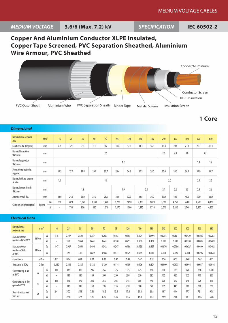
Copper And Aluminium Conductor XLPE Insulated, Copper Tape Screened, PVC Separation Sheathed, Aluminium Wire Armour, PVC Sheathed
1 Core
3.6/6 (Max. 7.2) kV
Binder TapePVC Outer Sheath PVC Separation Sheath Metalic Screen Insulation Screen
XLPE Insulation
Conductor Screen
Copper/Aluminium
Aluminium Wire

Nominal cross sectional area
mm² 16 25 35 50 70 95 120 150 185 240 300 400 500 630
Conductor dia. (approx.) mm 4.7 5.9 7.0 8.1 9.7 11.4 12.8 14.3 16.0 18.4 20.6 23.3 26.3 30.3
Nominal insulation thickness
mm 3.4
Nominal separation thickness
mm 1.2 1.3 1.4
Separation sheath dia. (approx.)
mm 18.1 19.3 20.6 21.7 23.5 25.2 26.6 28.1 29.8 32.2 34.4 37.1 40.3 45.1
Nominal of hard-drawn Al wire
mm 1.6 2.0 2.5 2.5
Nominal outer-sheath thickness
mm 1.8 1.9 2.0 2.1 2.2 2.4 2.5 2.6
Approx. overall dia. mm 25.0 26.5 27.5 28.5 30.5 32.5 34.0 36.5 38.0 41.0 43.0 46.0 50.5 55.5
Cable net. weight (approx.)
kg/kmCu 820 970 1,110 1,270 1,560 1,880 2,180 2,600 3,010 3,700 4,340 5,280 6,550 8,200
Al - 810 890 970 1,130 1,280 1,420 1,670 1,850 2,150 2,420 2,820 3,450 4,190
Nominal cross sectional area
mm² 16 25 35 50 70 95 120 150 185 240 300 400 500 630
Max. conductor resistance DC at 20°C
Ω /kmCu 1.15 0.727 0.524 0.387 0.268 0.193 0.153 0.124 0.0991 0.0754 0.0601 0.0470 0.0366 0.0283
Al - 1.20 0.868 0.641 0.443 0.320 0.253 0.206 0.164 0.125 0.100 0.0778 0.0605 0.0469
Max. conductor resistance 50Hz at 90°C
Ω /kmCu 1.47 0.927 0.668 0.494 0.342 0.247 0.196 0.159 0.127 0.0976 0.0785 0.0624 0.0499 0.0402
Al - 1.54 1.11 0.822 0.568 0.411 0.325 0.265 0.211 0.161 0.129 0.101 0.0796 0.0628
Capacitance µF/km 0.17 0.19 0.22 0.24 0.27 0.31 0.33 0.36 0.40 0.44 0.48 0.53 0.59 0.68
Reactance at 50Hz Ω /km 0.158 0.147 0.139 0.132 0.125 0.118 0.113 0.111 0.107 0.102 0.0991 0.0957 0.0942 0.0921
Current rating In air at 40°C
ACu 115 150 180 215 270 325 375 430 495 585 665 770 890 1,030
Al - 115 140 165 210 255 290 335 385 455 520 610 710 830
Current rating In the ground at 25°C
ACu 115 145 175 205 255 305 345 390 435 505 570 645 725 815
Al - 115 135 160 195 235 270 300 340 395 445 510 580 660
Short circuit current for 1 sec.
kACu 2.41 3.72 5.18 7.36 10.2 13.8 17.4 21.8 26.8 34.7 43.4 57.7 72.1 90.8
Al - 2.48 3.45 4.89 6.80 9.19 11.5 14.4 17.7 22.9 28.6 38.1 47.6 59.8
FEC Cables (M) Sdn. Bhd.
16
MEDIUM VOLTAGE IEC 60502-2SPECIFICATION
Dimensional
Electrical Data
Copper And Aluminium Conductor XLPE Insulated, Copper Tape Screened, PVC Separation Sheathed, Aluminium Wire Armour, PVC Sheathed
1 Core
6/10 (Max. 12) kV
Binder TapePVC Outer Sheath PVC Separation Sheath Metalic Screen Insulation Screen
XLPE Insulation
Conductor Screen
Copper/Aluminium
Aluminium Wire

Nominal cross sectional area
mm² 16 25 35 50 70 95 120 150 185 240 300 400 500 630
Conductor dia. (approx.) mm - 5.9 7.0 8.1 9.7 11.4 12.8 14.3 16.0 18.4 20.6 23.3 26.3 30.3
Nominal insulation thickness
mm - 4.5
Nominal separation thickness
mm 1.2 1.3 1.3 1.4
Separation sheath dia. (approx.)
mm - 21.5 22.8 23.9 25.7 27.4 28.8 30.3 32.0 34.4 36.6 39.5 42.5 47.3
Nominal of hard-drawn Al wire
mm - 1.6 2.0 2.5
Nominal outer-sheath thickness
mm - 1.8 1.9 2.0 2.1 2.1 2.2 2.3 2.3 2.5 2.6 2.7
Approx. overall dia. mm - 28.5 30.0 31.0 33.0 35.5 37.0 38.5 40.5 43.0 45.5 49.5 53.0 58.0
Cable net. weight (approx.)
kg/kmCu - 1,090 1,250 1,420 1,700 2,120 2,440 2,760 3,210 3,890 4,550 5,680 6,800 8,450
Al - 930 1,030 1,120 1,270 1,530 1,680 1,830 2,050 2,350 2,630 3,220 3,700 4,440
Nominal cross sectional area
mm² 16 25 35 50 70 95 120 150 185 240 300 400 500 630
Max. conductor resistance DC at 20°C
Ω /kmCu - 0.727 0.524 0.387 0.268 0.193 0.153 0.124 0.0991 0.0754 0.0601 0.0470 0.0366 0.0283
Al - 1.20 0.868 0.641 0.443 0.320 0.253 0.206 0.164 0.125 0.100 0.0778 0.0605 0.0469
Max. conductor resis-tance 50Hz at 90°C
Ω /kmCu - 0.927 0.668 0.494 0.342 0.247 0.196 0.159 0.127 0.0975 0.0784 0.0623 0.0497 0.0400
Al - 1.54 1.11 0.822 0.568 0.411 0.325 0.265 0.211 0.161 0.129 0.101 0.0795 0.0627
Capacitance µF/km - 0.16 0.18 0.20 0.22 0.25 0.27 0.29 0.31 0.35 0.38 0.42 0.46 0.53
Reactance at 50Hz Ω /km - 0.152 0.144 0.137 0.129 0.124 0.119 0.115 0.111 0.106 0.102 0.100 0.0972 0.0948
Current rating In air at 40°C
ACu - 150 180 215 270 330 380 435 495 585 670 775 890 1,025
Al - 115 140 170 210 255 295 335 385 455 520 610 710 830
Current rating In the ground at 25°C
ACu - 145 175 205 255 305 345 385 435 505 565 645 725 810
Al - 115 135 160 195 235 270 300 340 395 445 510 580 660
Short circuit current for 1 sec.
kACu - 3.72 5.18 7.36 10.2 13.8 17.4 21.8 26.8 34.7 43.4 57.7 72.1 90.8
Al - 2.48 3.45 4.89 6.80 9.19 11.5 14.4 17.7 22.9 28.6 38.1 47.6 59.8
MEDIUM VOLTAGE CABLES
17
Dimensional
MEDIUM VOLTAGE IEC 60502-2SPECIFICATION
Electrical Data
Copper And Aluminium Conductor XLPE Insulated, Copper Tape Screened, PVC Separation Sheathed, Aluminium Wire Armour, PVC Sheathed
1 Core
8.7/15 (Max. 17.5) kV
Binder TapePVC Outer Sheath PVC Separation Sheath Metalic Screen Insulation Screen
XLPE Insulation
Conductor Screen
Copper/Aluminium
Aluminium Wire

Nominal cross sectional area
mm² 16 25 35 50 70 95 120 150 185 240 300 400 500 630
Conductor dia. (approx.) mm - - 7.0 8.1 9.7 11.4 12.8 14.3 16.0 18.4 20.6 23.3 26.3 30.3
Nominal insulation thickness
mm - - 5.5
Nominal separation thickness
mm - 1.2 1.3 1.4
Separation sheath dia. (approx.)
mm - - 24.6 25.7 27.5 29.2 30.6 32.1 33.8 36.2 38.6 41.3 44.5 49.1
Nominal of hard-drawn Al wire
mm - - 1.6 2.0 2.5
Nominal outer-sheath thickness
mm - - 1.9 2.0 2.0 2.1 2.1 2.2 2.2 2.3 2.4 2.5 2.6 2.8
Approx. overall dia. mm - - 32.0 33.0 35.5 37.5 39.0 40.5 42.5 45.0 48.5 51.5 55.0 60.0
Cable net. weight (approx.) kg/kmCu - - 1,360 1,540 1,910 2,260 2,560 2,910 3,340 4,040 4,890 5,840 6,990 8,660
Al - - 1,140 1,240 1,480 1,660 1,800 1,980 2,180 2,490 2,970 3,380 3,890 4,660
Nominal cross sectional area
mm² 16 25 35 50 70 95 120 150 185 240 300 400 500 630
Max. conductor resistance DC at 20°C
Ω /kmCu - - 0.524 0.387 0.268 0.193 0.153 0.124 0.0991 0.0754 0.0601 0.0470 0.0366 0.0283
Al - - 0.868 0.641 0.443 0.320 0.253 0.206 0.164 0.125 0.100 0.0778 0.0605 0.0469
Max. conductor resistance 50Hz at 90°C
Ω /kmCu - - 0.668 0.494 0.342 0.247 0.196 0.159 0.127 0.0975 0.0783 0.0622 0.0496 0.0399
Al - - 1.11 0.822 0.568 0.411 0.325 0.265 0.211 0.161 0.129 0.101 0.0794 0.0626
Capacitance µF/km - - 0.16 0.17 0.19 0.21 0.23 0.25 0.27 0.30 0.32 0.35 0.39 0.44
Reactance at 50Hz Ω /km - - 0.148 0.141 0.134 0.127 0.122 0.118 0.114 0.109 0.106 0.102 0.0995 0.0969
Current rating In air at 40°C
ACu - - 185 220 275 335 380 435 495 585 675 775 890 1,025.0
Al - - 140 170 210 260 295 335 385 455 525 610 710 830
Current rating In the ground at 25°C
ACu - - 175 205 255 305 345 385 435 505 570 645 725 810
Al - - 135 160 195 235 270 300 340 395 445 510 580 660
Short circuit current for 1 sec.
kACu - - 5.18 7.36 10.2 13.8 17.4 21.8 26.8 34.7 43.4 57.7 72.1 90.8
Al - - 3.45 4.89 6.80 9.19 11.5 14.4 17.7 22.9 28.6 38.1 47.6 59.8
FEC Cables (M) Sdn. Bhd.
18
MEDIUM VOLTAGE IEC 60502-2SPECIFICATION
Dimensional
Electrical Data
Copper And Aluminium Conductor XLPE Insulated, Copper Tape Screened, PVC Separation Sheathed, Aluminium Wire Armour, PVC Sheathed
1 Core
12/20 (Max. 24) kV
Binder TapePVC Outer Sheath PVC Separation Sheath Metalic Screen Insulation Screen
XLPE Insulation
Conductor Screen
Copper/Aluminium
Aluminium Wire

Nominal cross sectional area
mm² 16 25 35 50 70 95 120 150 185 240 300 400 500 630
Conductor dia. (approx.) mm - - - 8.1 9.7 11.4 12.8 14.3 16.0 18.4 20.6 23.3 26.3 30.3
Nominal insulation thickness
mm - - - 8.0
Nominal separation thickness
mm - - 1.2 1.3 1.4 1.5
Separation sheath dia. (approx.)
mm - - - 30.8 32.6 34.3 35.7 37.4 39.1 41.5 43.9 46.6 49.8 54.4
Nominal of hard-drawn Al wire
mm - - - 2.0 2.5
Nominal outer-sheath thickness
mm - - - 2.2 2.3 2.4 2.5 2.6 2.7 2.8 2.9
Approx. overall dia. mm - - - 39.5 41.0 43.0 44.5 47.5 49.5 51.5 54.5 57.0 60.5 65.5
Cable net. weight (approx.) kg/kmCu - - - 2,000 2,300 2,670 2,990 3,500 3,980 4,680 5,420 6,400 7,580 9,290
Al - - - 1,700 1,870 2,070 2,230 2,580 2,810 3,140 3,500 3,940 4,480 5,280
Nominal cross sectional area
mm² 16 25 35 50 70 95 120 150 185 240 300 400 500 630
Max. conductor resistance DC at 20°C
Ω /kmCu - - - 0.387 0.268 0.193 0.153 0.124 0.0991 0.0754 0.0601 0.0470 0.0366 0.0283
Al - - - 0.641 0.443 0.320 0.253 0.206 0.164 0.125 0.100 0.0778 0.0605 0.0469
Max. conductor resis-tance 50Hz at 90°C
Ω /kmCu - - - 0.494 0.342 0.247 0.196 0.159 0.127 0.0974 0.0782 0.0620 0.0494 0.0396
Al - - - 0.822 0.568 0.411 0.325 0.265 0.211 0.161 0.129 0.101 0.0793 0.0624
Capacitance µF/km - - - 0.13 0.15 0.16 0.18 0.19 0.20 0.22 0.24 0.26 0.29 0.32
Reactance at 50Hz Ω /km - - - 0.152 0.143 0.136 0.130 0.128 0.123 0.117 0.113 0.109 0.105 0.102
Current rating In air at 40°C
ACu - - - 220 275 335 385 440 500 590 675 775 890 1025
Al - - - 170 215 260 300 340 390 460 525 610 710 825
Current rating In the ground at 25°C
ACu - - - 205 255 305 345 385 435 505 565 640 720 810
Al - - - 160 195 235 265 300 340 395 445 505 575 655
Short circuit current for 1 sec.
kACu - - - 7.36 10.2 13.8 17.4 21.8 26.8 34.7 43.4 57.7 72.1 90.8
Al - - - 4.89 6.80 9.19 11.5 14.4 17.7 22.9 28.6 38.1 47.6 59.8
MEDIUM VOLTAGE CABLES
19
Dimensional
MEDIUM VOLTAGE IEC 60502-2SPECIFICATION
Electrical Data
Copper And Aluminium Conductor XLPE Insulated, Copper Tape Screened, PVC Separation Sheathed, Aluminium Wire Armour, PVC Sheathed
1 Core
18/30 (Max. 36) kV
Binder TapePVC Outer Sheath PVC Separation Sheath Metalic Screen Insulation Screen
XLPE Insulation
Conductor Screen
Copper/Aluminium
Aluminium Wire

Nominal cross sectional area
mm² 16 25 35 50 70 95 120 150 185 240 300 400 500
Conductor dia. (approx.) mm 4.7 5.9 7.0 8.1 9.7 11.4 12.8 14.3 16.0 18.4 20.6 23.3 26.3
Nominal insulation thickness
mm 2.5 2.6 2.8 3.0 3.2
Nominal separation thickness
mm 1.2 1.3 1.4 1.5 1.6 1.7 1.8 2.0 2.1
Separation sheath dia. (approx.)
mm 31.6 34.2 37.0 39.6 43.7 47.3 50.6 53.8 57.7 63.5 69.3 76.3 83.9
Nominal of galvanized steel wire
mm 2.0 2.5 3.15
Nominal outer-sheath thickness
mm 2.2 2.3 2.5 2.6 2.7 2.8 2.9 3.0 3.2 3.5 3.8 4.0
Approx. overall dia. mm 40.5 43.0 46.0 50.0 54.0 58.0 61.5 65.0 69.0 75.0 83.0 90.5 98.5
Cable net. weight (approx.)
kg/kmCu 2,830 3,330 3,840 4,870 5,910 7,020 8,080 9,210 10,710 13,090 16,410 19,880 23,820
Al - 2,850 3,170 3,960 4,600 5,200 5,790 6,400 7,180 8,420 10,590 12,440 14,440
Nominal cross sectional area
mm² 16 25 35 50 70 95 120 150 185 240 300 400 500
Max. conductor resistance DC at 20°C
Ω /kmCu 1.15 0.727 0.524 0.387 0.268 0.193 0.153 0.124 0.0991 0.0754 0.0601 0.0470 0.0366
Al - 1.20 0.868 0.641 0.443 0.320 0.253 0.206 0.164 0.125 0.100 0.0778 0.0605
Max. conductor resistance 50Hz at 90°C
Ω /kmCu 1.47 0.927 0.668 0.494 0.342 0.247 0.196 0.160 0.128 0.0988 0.0800 0.0643 0.0522
Al - 1.54 1.11 0.822 0.568 0.411 0.325 0.265 0.211 0.161 0.130 0.102 0.0801
Capacitance µF/km 0.21 0.24 0.28 0.31 0.35 0.40 0.43 0.47 0.52 0.56 0.57 0.60 0.62
Reactance at 50Hz Ω /km 0.117 0.109 0.105 0.100 0.0949 0.0914 0.0885 0.0860 0.0837 0.0817 0.0805 0.0790 0.0779
Current rating In air at 40°C
ACu 105 135 165 195 245 300 340 385 440 515 585 665 745
Al - 105 130 155 190 235 270 305 345 405 460 530 605
Current rating In the ground at 25°C
ACu 110 140 170 200 245 290 330 365 415 475 530 590 650
Al - 110 130 155 190 225 255 285 320 370 415 470 530
Short circuit current for 1 sec.
kACu 2.41 3.72 5.18 7.36 10.2 13.8 17.4 21.8 26.8 34.7 43.4 57.7 72.1
Al - 2.48 3.45 4.89 6.80 9.19 11.5 14.4 17.7 22.9 28.6 38.1 47.6
FEC Cables (M) Sdn. Bhd.
20
MEDIUM VOLTAGE IEC 60502-2SPECIFICATION
Dimensional
Electrical Data
Copper And Aluminium Conductor XLPE Insulated, Copper Tape Screened, PVC Separation Sheathed, Zinc-Coated SteelWire Armour, PVC Sheathed
3 Core
3.6/6 (Max. 7.2) kV
PVC Outer Sheath PVC Separation Sheath Metalic ScreenInsulation Screen
XLPE Insulation
Conductor Screen
Copper/Aluminium
Galvanized Steel Wire
Binder Tape
Filler

Nominal cross sectional area
mm² 16 25 35 50 70 95 120 150 185 240 300 400 500
Conductor dia. (approx.) mm 4.7 5.9 7.0 8.1 9.7 11.4 12.8 14.3 16.0 18.4 20.6 23.3 26.3
Nominal insulation thickness
mm 3.4
Nominal separation thickness
mm 1.2 1.3 1.4 1.5 1.6 1.7 1.8 1.9 2.0 2.1
Separation sheath dia. (approx.)
mm 35.5 38.3 41.1 43.7 47.6 51.4 54.6 57.9 61.7 67.1 72.1 78.1 84.7
Nominal of galvanized steel wire
mm 2.0 2.5 3.15
Nominal outer-sheath thickness
mm 2.3 2.4 2.5 2.6 2.7 2.9 3.0 3.1 3.2 3.4 3.6 3.8 4.0
Approx. overall dia. mm 44.5 48.5 51.5 54.0 58.0 62.5 66.0 69.5 73.5 80.5 86.0 92.0 99.5
Cable net. weight (approx.) kg/kmCu 3,220 4,130 4,740 5,380 6,420 7,600 8,690 9,840 11,370 14,560 16,960 20,210 24,000
Al - 3,650 4,070 4,480 5,110 5,790 6,400 7,030 7,840 9,880 11,140 12,770 14,610
Nominal cross sectional area
mm² 16 25 35 50 70 95 120 150 185 240 300 400 500
Max. conductor resistance DC at 20°C
Ω /kmCu 1.15 0.727 0.524 0.387 0.268 0.193 0.153 0.124 0.0991 0.0754 0.0601 0.0470 0.0366
Al - 1.20 0.868 0.641 0.443 0.320 0.253 0.206 0.164 0.125 0.100 0.0778 0.0605
Max. conductor resis-tance 50Hz at 90°C
Ω /kmCu 1.47 0.927 0.668 0.494 0.342 0.247 0.196 0.160 0.128 0.0986 0.0798 0.0641 0.0521
Al - 1.54 1.11 0.822 0.568 0.411 0.325 0.265 0.211 0.161 0.130 0.102 0.0801
Capacitance µF/km 0.17 0.19 0.22 0.24 0.27 0.31 0.33 0.36 0.40 0.44 0.48 0.53 0.59
Reactance at 50Hz Ω /km 0.128 0.118 0.113 0.108 0.102 0.0976 0.0944 0.0915 0.0888 0.0856 0.0833 0.0809 0.0788
Current rating In air at 40°C
ACu 105 140 170 200 250 300 345 390 445 520 585 665 745
Al - 110 130 155 195 235 270 305 345 410 460 530 605
Current rating In the ground at 25°C
ACu 110 140 170 200 245 290 330 365 410 475 525 590 650
Al - 110 130 155 190 225 255 285 320 370 415 470 530
Short circuit current for 1 sec.
kACu 2.41 3.72 5.18 7.36 10.2 13.8 17.4 21.8 26.8 34.7 43.4 57.7 72.1
Al - 2.48 3.45 4.89 6.80 9.19 11.5 14.4 17.7 22.9 28.6 38.1 47.6
MEDIUM VOLTAGE CABLES
21
Dimensional
MEDIUM VOLTAGE IEC 60502-2SPECIFICATION
Electrical Data
Copper And Aluminium Conductor XLPE Insulated, Copper Tape Screened, PVC Separation Sheathed, Zinc-Coated SteelWire Armour, PVC Sheathed
3 Core
6/10 (Max. 12) kV
PVC Outer Sheath PVC Separation Sheath Metalic ScreenInsulation Screen
XLPE Insulation
Conductor Screen
Copper/Aluminium
Galvanized Steel Wire
Binder Tape
Filler

Nominal cross sectional area mm² 16 25 35 50 70 95 120 150 185 240 300 400 500
Conductor dia. (approx.) mm - 5.9 7.0 8.1 9.7 11.4 12.8 14.3 16.0 18.4 20.6 23.3 26.3
Nominal insulation thickness mm - 4.5
Nominal separation thickness mm - 1.4 1.5 1.6 1.7 1.8 1.9 2.0 2.1 2.2
Separation sheath dia. (approx.)
mm - 43.3 46.1 48.7 52.6 56.4 59.7 62.9 66.7 72.1 77.1 83.1 89.7
Nominal of galvanized steel wire
mm - 2.5 3.15
Nominal outer-sheath thickness
mm - 2.6 2.7 2.8 2.9 3.0 3.1 3.2 3.4 3.6 3.7 4.0 4.2
Approx. overall dia. mm - 54.0 57.0 59.5 63.5 67.5 71.0 74.5 80.0 86.0 91.0 97.5 104.5
Cable net. weight (approx.) kg/kmCu - 4,790 5,420 6,080 7,160 8,350 9,460 10,640 13,090 15,550 17,950 21,300 25,140
Al - 4,310 4,760 5,180 5,850 6,530 7,170 7,820 9,560 10,870 12,130 13,860 15,760
Nominal cross sectional area
mm² 16 25 35 50 70 95 120 150 185 240 300 400 500
Max. conductor resistance DC at 20°C
Ω /kmCu - 0.727 0.524 0.387 0.268 0.193 0.153 0.124 0.0991 0.0754 0.0601 0.0470 0.0366
Al - 1.20 0.868 0.641 0.443 0.320 0.253 0.206 0.164 0.125 0.100 0.0778 0.0605
Max. conductor resis-tance 50Hz at 90°C
Ω /kmCu - 0.927 0.668 0.494 0.342 0.247 0.196 0.159 0.128 0.0983 0.0794 0.0636 0.0515
Al - 1.54 1.11 0.822 0.568 0.411 0.325 0.265 0.211 0.161 0.130 0.102 0.0799
Capacitance µF/km - 0.16 0.18 0.20 0.22 0.25 0.27 0.29 0.31 0.35 0.38 0.42 0.46
Reactance at 50Hz Ω /km - 0.131 0.124 0.118 0.112 0.107 0.103 0.0994 0.0962 0.0924 0.0896 0.0868 0.0842
Current rating In air at 40°C
ACu - 140 170 200 250 305 350 395 450 520 590 665 750
Al - 110 130 155 195 235 270 305 350 410 465 535 610
Current rating In the ground at 25°C
ACu - 140 170 200 245 290 330 370 410 475 530 590 650
Al - 110 130 155 190 225 255 285 320 370 415 470 530
Short circuit current for 1 sec.
kACu - 3.72 5.18 7.36 10.2 13.8 17.4 21.8 26.8 34.7 43.4 57.7 72.1
Al - 2.48 3.45 4.89 6.80 9.19 11.5 14.4 17.7 22.9 28.6 38.1 47.6
FEC Cables (M) Sdn. Bhd.
22
MEDIUM VOLTAGE IEC 60502-2SPECIFICATION
Dimensional
Electrical Data
Copper And Aluminium Conductor XLPE Insulated, Copper Tape Screened, PVC Separation Sheathed, Zinc-Coated SteelWire Armour, PVC Sheathed
3 Core
8.7/15 (Max. 17.5) kV
PVC Outer Sheath PVC Separation Sheath Metalic ScreenInsulation Screen
XLPE Insulation
Conductor Screen
Copper/Aluminium
Galvanized Steel Wire
Binder Tape
Filler
Nominal cross sectional area mm² 16 25 35 50 70 95 120 150 185 240 300 400 500
Conductor dia. (approx.) mm - - 7.0 8.1 9.7 11.4 12.8 14.3 16.0 18.4 20.6 23.3 -
Nominal insulation thickness mm - - 5.5 -
Nominal separation thickness
mm - - 1.5 1.6 1.7 1.8 1.9 2.0 2.2 -
Separation sheath dia. (approx.)
mm - - 50.2 52.8 56.6 60.5 63.5 67.0 70.8 76.2 80.9 87.2 -
Nominal of galvanized steel wire
mm - - 2.5 3.15
Nominal outer-sheath thickness
mm - - 2.8 2.9 3.1 3.2 3.3 3.4 3.6 3.7 3.9 4.1 -
Approx. overall dia. mm - - 61.0 64.0 68.0 72.0 76.5 80.5 84.5 90.0 95.5 102.0 -
Cable net. weight (approx.) kg/kmCu - - 5,980 6,660 7,740 9,000 10,930 12,190 13,870 16,330 18,770 22,150 -
Al - - 5,310 5,750 6,440 7,190 8,640 9,380 10,340 11,650 12,950 14,710 -
Nominal cross sectional area
mm² 16 25 35 50 70 95 120 150 185 240 300 400 -
Max. conductor resistance DC at 20°C
Ω /kmCu - - 0.524 0.387 0.268 0.193 0.153 0.124 0.0991 0.0754 0.0601 0.0470 -
Al - - 0.868 0.641 0.443 0.320 0.253 0.206 0.164 0.125 0.100 0.0778 -
Max. conductor resistance 50Hz at 90°C
Ω /kmCu - - 0.668 0.494 0.342 0.247 0.196 0.159 0.128 0.0981 0.0792 0.0634 -
Al - - 1.11 0.822 0.568 0.411 0.325 0.265 0.211 0.161 0.129 0.101 -
Capacitance µF/km - - 0.16 0.17 0.19 0.21 0.23 0.25 0.27 0.30 0.32 0.35 -
Reactance at 50Hz Ω /km - - 0.130 0.124 0.117 0.112 0.108 0.104 0.100 0.0963 0.0933 0.0902 -
Current rating In air at 40°C
ACu - - 170 205 250 305 350 395 450 520 590 665 -
Al - - 135 160 195 240 275 310 350 410 465 535 -
Current rating In the ground at 25°C
ACu - - 170 200 240 290 330 365 410 470 525 585 -
Al - - 130 155 190 225 255 285 320 370 415 470 -
Short circuit current for 1 sec.
kACu - - 5.18 7.36 10.2 13.8 17.4 21.8 26.8 34.7 43.4 57.7 -
Al - - 3.45 4.89 6.80 9.19 11.5 14.4 17.7 22.9 28.6 38.1 -
MEDIUM VOLTAGE CABLES
23
Dimensional
MEDIUM VOLTAGE IEC 60502-2SPECIFICATION
Electrical Data
Copper And Aluminium Conductor XLPE Insulated, Copper Tape Screened, PVC Separation Sheathed, Zinc-Coated SteelWire Armour, PVC Sheathed
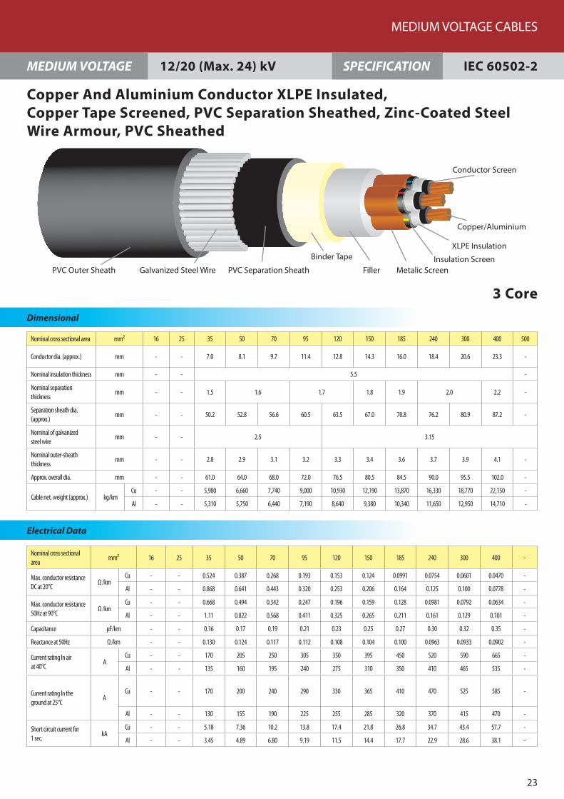
3 Core
12/20 (Max. 24) kV
PVC Outer Sheath PVC Separation Sheath Metalic ScreenInsulation Screen
XLPE Insulation
Conductor Screen
Copper/Aluminium
Galvanized Steel Wire
Binder Tape
Filler

Nominal cross sectional area mm² 16 25 35 50 70 95 120 150 185 240 300 400 500
Conductor dia. (approx.) mm - - - 8.1 9.7 11.4 12.8 14.3 16.0 18.4 20.6 - -
Nominal insulation thickness mm - - - 8.0 - -
Nominal separation thickness mm - - - 1.8 1.9 2.0 2.1 2.2 2.3 - -
Separation sheath dia. (approx.)
mm - - - 64.2 68.0 71.9 75.1 78.4 82.2 87.6 92.5 - -
Nominal of galvanized steel wire
mm - - - 3.15 -
Nominal outer-sheath thickness
mm - - - 3.4 3.5 3.6 3.7 3.8 4.0 4.1 4.3 - -
Approx. overall dia. mm - - - 77.5 81.5 85.5 89.0 92.5 97.0 102.5 107.5 - -
Cable net. weight (approx.) kg/kmCu - - - 9,310 10,470 11,850 13,080 14,360 16,120 18,670 21,240 - -
Al - - - 8,410 9,160 10,040 10,790 11,550 12,590 13,990 15,420 - -
Nominal cross sectional area mm² 16 25 35 50 70 95 120 150 185 240 300 400 500
Max. conductor resistance DC at 20°C
Ω /kmCu - - - 0.387 0.268 0.193 0.153 0.124 0.0991 0.0754 0.0601 - -
Al - - - 0.641 0.443 0.320 0.253 0.206 0.164 0.125 0.100 - -
Max. conductor resistance 50Hz at 90°C
Ω /kmCu - - - 0.494 0.342 0.247 0.196 0.159 0.128 0.0978 0.0789 - -
Al - - - 0.822 0.568 0.411 0.325 0.265 0.211 0.161 0.129 - -
Capacitance µF/km - - - 0.13 0.15 0.16 0.18 0.19 0.20 0.22 0.24 - -
Reactance at 50Hz Ω /km - - - 0.137 0.129 0.123 0.118 0.114 0.110 0.105 0.102 - -
Current rating In air at 40°C ACu - - - 205 255 310 350 395 450 520 590 - -
Al - - - 160 200 240 275 310 350 410 465 - -
Current rating In the ground at 25°C
ACu - - - 200 240 290 325 365 410 470 525 - -
Al - - - 155 190 225 255 285 320 370 415 - -
Short circuit current for 1 sec. kACu - - - 7.36 10.2 13.8 17.4 21.8 26.8 34.7 43.4 - -
Al - - - 4.89 6.80 9.19 11.5 14.4 17.7 22.9 28.6 - -
FEC Cables (M) Sdn. Bhd.
2�
MEDIUM VOLTAGE IEC 60502-2SPECIFICATION
Dimensional
Electrical Data
Copper And Aluminium Conductor XLPE Insulated, Copper Tape Screened, PVC Separation Sheathed, Zinc-Coated SteelWire Armour, PVC Sheathed
3 Core
18/30 (Max. 36) kV
PVC Outer Sheath PVC Separation Sheath Metalic ScreenInsulation Screen
XLPE Insulation
Conductor Screen
Copper/Aluminium
Galvanized Steel Wire
Binder Tape
Filler

Nominal cross sectional area
mm² 16 25 35 50 70 95 120 150 185 240 300 400 500
Conductor dia. (approx.) mm 4.7 5.9 7.0 8.1 9.7 11.4 12.8 14.3 16.0 18.4 20.6 23.3 26.3
Nominal insulation thickness
mm 2.5 2.6 2.8 3.0 3.2
Nominal separation thickness
mm 1.2 1.3 1.4 1.5 1.6 1.7 1.8 2.0 2.1
Separation sheath dia. (approx.)
mm 31.6 34.2 37.0 39.6 43.7 47.3 50.6 53.8 57.7 63.5 69.3 76.3 83.9
Nominal of galvanized steel tape
mm 0.2 0.5 0.8
Nominal outer-sheath thickness
mm 2.1 2.2 2.3 2.4 2.5 2.6 2.7 2.8 2.9 3.1 3.3 3.6 3.9
Approx. overall dia. mm 37.0 41.0 44.0 46.5 51.0 55.0 58.0 61.5 65.5 72.0 78.0 87.0 95.0
Cable net. weight (approx.)
kg/kmCu 1,790 2,620 3,110 3,660 4,570 5,590 6,560 7,590 8,960 11,170 13,420 17,500 21,260
Al - 2,140 2,440 2,750 3,260 3,780 4,270 4,770 5,430 6,490 7,600 10,050 11,870
Nominal cross sectional area
mm² 16 25 35 50 70 95 120 150 185 240 300 400 500
Max. conductor resistance DC at 20°C
Ω /kmCu 1.15 0.727 0.524 0.387 0.268 0.193 0.153 0.124 0.0991 0.0754 0.0601 0.0470 0.0366
Al - 1.20 0.868 0.641 0.443 0.320 0.253 0.206 0.164 0.125 0.100 0.0778 0.0605
Max. conductor resis-tance 50Hz at 90°C
Ω /kmCu 1.47 0.927 0.668 0.494 0.342 0.247 0.196 0.160 0.128 0.0988 0.0800 0.0643 0.0522
Al - 1.54 1.11 0.866 0.568 0.411 0.325 0.265 0.211 0.161 0.130 0.102 0.0801
Capacitance µF/km 0.21 0.24 0.28 0.31 0.35 0.40 0.43 0.47 0.52 0.56 0.57 0.60 0.62
Reactance at 50Hz Ω /km 0.118 0.109 0.105 0.100 0.0949 0.0914 0.0885 0.0860 0.0837 0.0817 0.0805 0.0790 0.0779
Current rating In air at 40°C
ACu 100 135 160 195 240 295 340 385 440 520 590 680 775
Al - 105 130 155 190 235 270 305 350 410 470 545 630
Current rating In the ground at 25°C
ACu 110 140 170 200 240 290 330 370 415 480 540 610 685
Al - 110 130 155 190 225 255 285 325 375 425 485 555
Short circuit current for 1 sec.
kACu 2.41 3.72 5.18 7.36 10.2 13.8 17.4 21.8 26.8 34.7 43.4 57.7 72.1
Al - 2.48 3.45 4.89 6.80 9.19 11.5 14.4 17.7 22.9 28.6 38.1 47.6
MEDIUM VOLTAGE CABLES
25
Dimensional
MEDIUM VOLTAGE IEC 60502-2SPECIFICATION
Electrical Data
Copper And Aluminium Conductor XLPE Insulated, Copper Tape Screened, PVC Separation Sheathed, Zinc-Coated SteelTape Armour, PVC Sheathed
3 Core
3.6/6 (Max. 7.2) kV
m
PVC Outer SheathGalvanized Steel Tape(Double Tape)
PVC Separation Sheath Metalic Screen
Insulation Screen
XLPE Insulation
Conductor Screen
Copper/Aluminiu
Binder Tape
Filler

Nominal cross sectional area mm² 16 25 35 50 70 95 120 150 185 240 300 400 500
Conductor dia. (approx.) mm 4.7 5.9 7.0 8.1 9.7 11.4 12.8 14.3 16.0 18.4 20.6 23.3 26.3
Nominal insulation thickness
mm 3.4
Nominal separation thickness
mm 1.2 1.3 1.4 1.5 1.6 1.7 1.8 1.9 2.0 2.1
Separation sheath dia. (approx.)
mm 35.5 38.3 41.1 43.7 47.6 51.4 54.6 57.9 61.7 67.1 72.1 78.1 84.7
Nominal of galvanized steel tape
mm 0.5 0.8
Nominal outer-sheath thickness
mm 2.2 2.3 2.4 2.5 2.6 2.7 2.9 3.0 3.1 3.3 3.4 3.7 3.9
Approx. overall dia. mm 42.0 45.0 48.0 51.0 55.0 59.0 62.5 66.0 70.0 76.0 81.0 89.0 96.0
Cable net. weight (approx.) kg/kmCu 2,490 2,980 3,480 4,050 4,960 6,030 7,050 8,100 9,500 11,690 13,830 17,790 21,400
Al - 2,500 2,810 3,140 3,650 4,220 4,760 5,280 5,970 7,020 8,010 10,350 12,010
Nominal cross sectional area
mm² 16 25 35 50 70 95 120 150 185 240 300 400 500
Max. conductor resistance DC at 20°C
Ω /kmCu 1.15 0.727 0.524 0.387 0.268 0.193 0.153 0.124 0.0991 0.0754 0.0601 0.0470 0.0366
Al - 1.20 0.868 0.641 0.443 0.320 0.253 0.206 0.164 0.125 0.100 0.0778 0.0605
Max. conductor resistance 50Hz at 90°C
Ω /kmCu 1.47 0.927 0.668 0.494 0.342 0.247 0.196 0.160 0.128 0.0986 0.0798 0.0641 0.0521
Al - 1.54 1.11 0.822 0.568 0.411 0.325 0.265 0.211 0.161 0.130 0.102 0.0801
Capacitance µF/km 0.17 0.19 0.22 0.24 0.27 0.31 0.33 0.36 0.40 0.44 0.48 0.53 0.59
Reactance at 50Hz Ω /km 0.128 0.118 0.113 0.108 0.102 0.0976 0.0944 0.0915 0.0888 0.0856 0.0833 0.0809 0.0788
Current rating In air at 40°C
ACu 105 135 165 195 245 300 340 385 445 520 590 680 775
Al - 105 130 155 190 230 265 300 345 405 465 540 625
Current rating In the ground at 25°C
ACu 110 140 170 200 240 290 330 370 415 480 540 610 685
Al - 110 130 155 190 225 255 285 325 375 425 485 555
Short circuit current for 1 sec.
kACu 2.41 3.72 5.18 7.36 10.2 13.8 17.4 21.8 26.8 34.7 43.4 57.7 72.1
Al - 2.48 3.45 4.89 6.80 9.19 11.5 14.4 17.7 22.9 28.6 38.1 47.6
FEC Cables (M) Sdn. Bhd.
26
MEDIUM VOLTAGE IEC 60502-2SPECIFICATION
Dimensional
Electrical Data
Copper And Aluminium Conductor XLPE Insulated, Copper Tape Screened, PVC Separation Sheathed, Zinc-Coated SteelTape Armour, PVC Sheathed
3 Core
6/10 (Max. 12) kV
m
PVC Outer SheathGalvanized Steel Tape(Double Tape)
PVC Separation Sheath Metalic Screen
Insulation Screen
XLPE Insulation
Conductor Screen
Copper/Aluminiu
Binder Tape
Filler

Nominal cross sectional area
mm² 16 25 35 50 70 95 120 150 185 240 300 400 500
Conductor dia. (approx.) mm - 5.9 7.0 8.1 9.7 11.4 12.8 14.3 16.0 18.4 20.6 23.3 26.3
Nominal insulation thickness
mm - 4.5
Nominal separation thickness
mm - 1.4 1.5 1.6 1.7 1.8 1.9 2.0 2.1 2.2
Separation sheath dia. (approx.)
mm - 43.3 46.1 48.7 52.6 56.4 59.7 62.9 66.7 72.1 77.1 83.1 89.7
Nominal of galvanized steel tape
mm - 0.5 0.8
Nominal outer-sheath thickness
mm - 2.5 2.6 2.7 2.8 2.9 3.0 3.1 3.3 3.4 3.6 3.9 4.1
Approx. overall dia. mm - 50.5 53.5 56.5 60.5 64.5 68.0 71.5 75.5 81.0 87.5 94.5 101.5
Cable net. weight (approx.)
kg/kmCu - 3,490 4,020 4,600 5,550 6,650 7,670 8,750 10,210 12,420 15,570 18,720 22,380
Al - 3,010 3,350 3,700 4,240 4,840 5,380 5,930 6,680 7,750 9,750 11,270 12,990
Nominal cross sectional area
mm² 16 25 35 50 70 95 120 150 185 240 300 400 500
Max. conductor resistance DC at 20°C
Ω /kmCu - 0.727 0.524 0.387 0.268 0.193 0.153 0.124 0.0991 0.0754 0.0601 0.0470 0.0366
Al - 1.20 0.868 0.641 0.443 0.320 0.253 0.206 0.164 0.125 0.100 0.0778 0.0605
Max. conductor resistance 50Hz at 90°C
Ω /kmCu - 0.927 0.668 0.494 0.342 0.247 0.196 0.159 0.128 0.0983 0.0794 0.0636 0.0515
Al - 1.54 1.11 0.822 0.568 0.411 0.325 0.265 0.211 0.161 0.130 0.102 0.0799
Capacitance µF/km - 0.16 0.18 0.20 0.22 0.25 0.27 0.29 0.31 0.35 0.38 0.42 0.46
Reactance at 50Hz Ω /km - 0.131 0.124 0.118 0.112 0.107 0.103 0.0994 0.0962 0.0924 0.0896 0.0868 0.0842
Current rating In air at 40°C
ACu - 140 170 200 250 300 345 395 450 525 600 685 780
Al - 105 130 155 195 235 270 305 350 410 470 545 630
Current rating In the ground at 25°C
ACu - 140 170 200 245 290 330 370 415 480 540 610 690
Al - 110 130 155 190 225 255 285 325 375 425 485 555
Short circuit current for 1 sec.
kACu - 3.72 5.18 7.36 10.2 13.8 17.4 21.8 26.8 34.7 43.4 57.7 72.1
Al - 2.48 3.45 4.89 6.80 9.19 11.5 14.4 17.7 22.9 28.6 38.1 47.6
MEDIUM VOLTAGE CABLES
27
Dimensional
MEDIUM VOLTAGE IEC 60502-2SPECIFICATION
Electrical Data
Copper And Aluminium Conductor XLPE Insulated, Copper Tape Screened, PVC Separation Sheathed, Zinc-Coated SteelTape Armour, PVC Sheathed
3 Core
8.7/15 (Max. 17.5) kV
m
PVC Outer SheathGalvanized Steel Tape(Double Tape)
PVC Separation Sheath Metalic Screen
Insulation Screen
XLPE Insulation
Conductor Screen
Copper/Aluminiu
Binder Tape
Filler

Nominal cross sectional area
mm² 16 25 35 50 70 95 120 150 185 240 300 400 500
Conductor dia. (approx.) mm - - 7.0 8.1 9.7 11.4 12.8 14.3 16.0 18.4 20.6 23.3 26.3
Nominal insulation thickness
mm - - 5.5
Nominal separation thickness
mm - - 1.5 1.6 1.7 1.8 1.9 2.0 2.0 2.2 2.3
Separation sheath dia. (approx.)
mm - - 50.2 52.8 56.6 60.5 63.5 67.0 70.8 76.2 80.9 87.2 93.8
Nominal of galvanized steel tape
mm - - 0.5 0.8
Nominal outer-sheath thickness
mm - - 2.7 2.8 2.9 3.1 3.2 3.3 3.4 3.6 3.8 4.0 4.2
Approx. overall dia. mm - - 58.0 60.5 64.5 69.0 72.0 76.0 80.0 87.0 92.0 98.5 105.5
Cable net. weight (approx.)
kg/kmCu - - 4,450 5,050 6,020 7,180 8,190 9,320 10,780 13,980 16,240 19,440 23,140
Al - - 3,780 4,150 4,720 5,370 5,900 6,510 7,250 9,300 10,420 11,990 13,760
Nominal cross sectional area
mm² 16 25 35 50 70 95 120 150 185 240 300 400 500
Max. conductor resistance DC at 20°C
Ω /kmCu - - 0.524 0.387 0.268 0.193 0.153 0.124 0.0991 0.0754 0.0601 0.0470 0.0366
Al - - 0.868 0.641 0.443 0.320 0.253 0.206 0.164 0.125 0.100 0.0778 0.0605
Max. conductor resis-tance 50Hz at 90°C
Ω /kmCu - - 0.668 0.494 0.342 0.247 0.196 0.159 0.128 0.0981 0.0792 0.0634 0.0512
Al - - 1.11 0.822 0.568 0.411 0.325 0.265 0.211 0.161 0.130 0.101 0.0798
Capacitance µF/km - - 0.16 0.17 0.19 0.21 0.23 0.25 0.27 0.30 0.32 0.35 0.39
Reactance at 50Hz Ω /km - - 0.130 0.124 0.117 0.112 0.108 0.104 0.100 0.0963 0.0933 0.0902 0.0873
Current rating In air at 40°C
ACu - - 170 200 250 305 350 395 450 530 600 685 780
Al - - 130 155 190 235 270 305 350 415 470 545 630
Current rating In the ground at 25°C
ACu - - 170 200 245 290 330 370 415 480 545 615 690
Al - - 130 155 190 225 255 285 325 375 425 485 555
Short circuit current for 1 sec.
kACu - - 5.18 7.36 10.2 13.8 17.4 21.8 26.8 34.7 43.4 57.7 72.1
Al - - 3.45 4.89 6.80 9.19 11.5 14.4 17.7 22.9 28.6 38.1 47.6
FEC Cables (M) Sdn. Bhd.
28
MEDIUM VOLTAGE IEC 60502-2SPECIFICATION
Dimensional
Electrical Data
Copper And Aluminium Conductor XLPE Insulated, Copper Tape Screened, PVC Separation Sheathed, Zinc-Coated SteelTape Armour, PVC Sheathed
3 Core
12/20 (Max. 24) kV
m
PVC Outer SheathGalvanized Steel Tape(Double Tape)
PVC Separation Sheath Metalic Screen
Insulation Screen
XLPE Insulation
Conductor Screen
Copper/Aluminiu
Binder Tape
Filler
Nominal cross sectional area
mm² 16 25 35 50 70 95 120 150 185 240 300 400 500
Conductor dia. (approx.) mm - - - 8.1 9.7 11.4 12.8 14.3 16.0 18.4 20.6 - -
Nominal insulation thickness
mm - - - 8.0 - -
Nominal separation thickness
mm - - - 1.8 1.9 2.0 2.0 2.1 2.2 2.3 - -
Separation sheath dia. (approx.)
mm - - - 64.2 68.0 71.9 75.1 78.4 82.2 87.6 92.5 - -
Nominal of galvanized steel tape
mm - - - 0.5 0.8 - -
Nominal outer-sheath thickness
mm - - - 3.2 3.3 3.5 3.6 3.7 3.9 4.0 4.2 - -
Approx. overall dia. mm - - - 73.0 77.0 81.0 86.0 89.0 93.5 99.0 104.5 - -
Cable net. weight (approx.)
kg/kmCu - - - 6,480 7,520 8,750 10,760 11,950 13,570 15,970 18,370 - -
Al - - - 5,580 6,210 6,940 8,470 9,140 10,040 11,290 12,550 - -
Nominal cross sectional area
mm² 16 25 35 50 70 95 120 150 185 240 300 400 500
Max. conductor resistance DC at 20°C
Ω /kmCu - - - 0.387 0.268 0.193 0.153 0.124 0.0991 0.0754 0.0601 - -
Al - - - 0.641 0.443 0.320 0.253 0.206 0.164 0.125 0.100 - -
Max. conductor resistance 50Hz at 90°C
Ω /kmCu - - - 0.494 0.342 0.247 0.196 0.159 0.128 0.0978 0.0789 - -
Al - - - 0.822 0.568 0.411 0.325 0.265 0.211 0.161 0.129 - -
Capacitance µF/km - - - 0.13 0.15 0.16 0.18 0.19 0.20 0.22 0.24 - -
Reactance at 50Hz Ω /km - - - 0.137 0.129 0.123 0.118 0.114 0.110 0.105 0.102 - -
Current rating In air at 40°C
ACu - - - 205 255 305 350 395 450 530 600 - -
Al - - - 160 195 240 275 310 355 415 475 - -
Current rating In the ground at 25°C
ACu - - - 200 240 290 330 370 415 480 540 - -
Al - - - 155 190 225 255 285 325 375 425 - -
Short circuit current for 1 sec.
kACu - - - 7.36 10.2 13.8 17.4 21.8 26.8 34.7 43.4 - -
Al - - - 4.89 6.80 9.19 11.5 14.4 17.7 22.9 28.6 - -
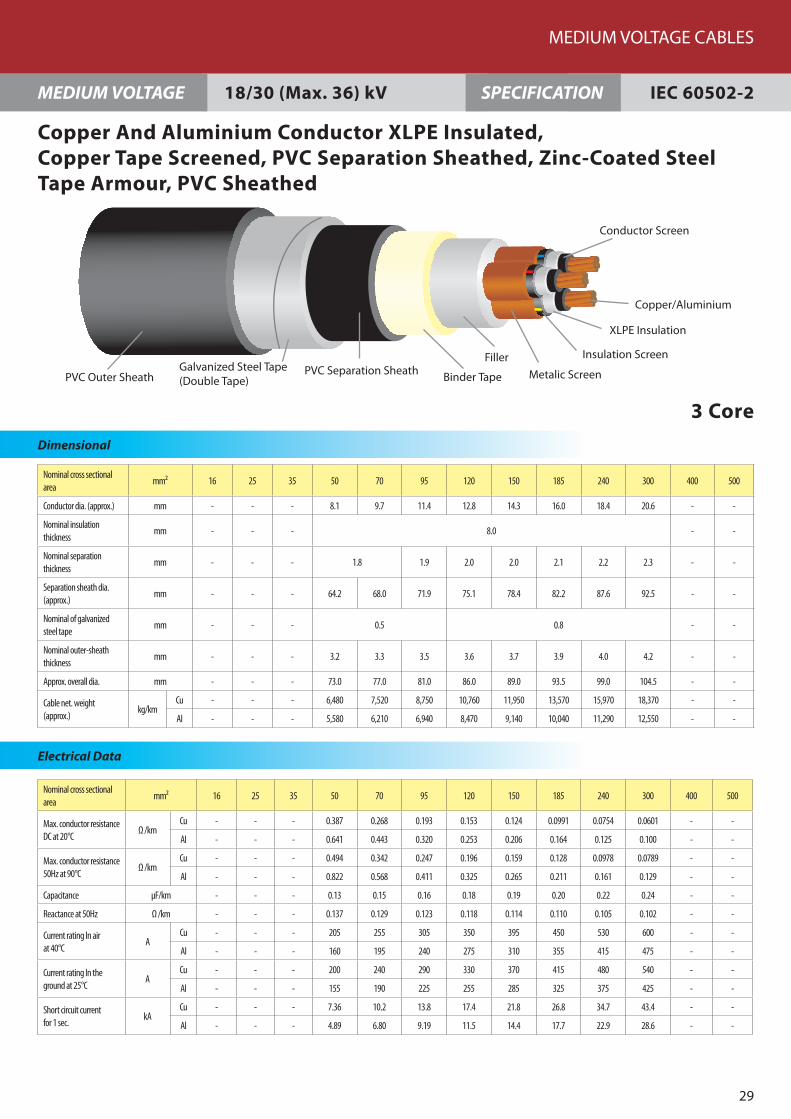
MEDIUM VOLTAGE CABLES
29
Dimensional
MEDIUM VOLTAGE IEC 60502-2SPECIFICATION
Electrical Data
Copper And Aluminium Conductor XLPE Insulated, Copper Tape Screened, PVC Separation Sheathed, Zinc-Coated SteelTape Armour, PVC Sheathed
3 Core
18/30 (Max. 36) kV
m
PVC Outer SheathGalvanized Steel Tape(Double Tape)
PVC Separation Sheath Metalic Screen
Insulation Screen
XLPE Insulation
Conductor Screen
Copper/Aluminiu
Binder Tape
Filler

The thermally permissible short circuit current for a conductor of specified size may be calculated from the equations below (based on IEC 609�9). For purposes of calculation, the standard short circuit duration period is up to 5 sec.
1. Copper Conductor :
2. Aluminium Conductor :
where s : conductor size in mm²
t : short circuit period in seconds
Short Circuit Current
Calculation Base for Electrical Characteristics
Installation
In air (Ambient temperature : 40 °C) In the ground (Ambient temperature : 25 °C)
Multi-core cable Single-core cable
Correction Factors For Continuous Current Rating
Ambient Temperature (°C)
Instalation15 20 25 30 35 �0 �5 50 55
In Air 1.22 1.18 1.1� 1.10 1.05 1.0 0.95 0.89 0.8�
In Ground 1.07 1.0� 1.0 0.96 0.92 0.88 0.83 0.78 0.73
I =1�3 • S
t1 + 0.�1 + 0.12t
sts (A)
I =9� • S
t1 + 0.57 + 0.16t
sts (A)
Multi-core cable Single-core cable
GroundLevel
700
mm
700
mm
Thermal Resistivity :120° C. cm/W
FEC Cables (M) Sdn. Bhd.
30


Factory 1Persiaran Raja Muda, �0000 Shah Alam, Selangor Darul Ehsan, Malaysia.(P.O. Box 7006, �0700 Shah Alam)Tel : 6 03 - 5519 1110 (Hotline) Fax : 6 03 - 5519 1296
Factory 2No. 16, Jalan Keluli 2, Bukit Raja Industrial Area, �1050 Klang, Selangor Darul Ehsan, Malaysia. Tel : 6 03 - 33�3 5837 (Hotline) Fax : 6 03 - 33�3 58�3
Sales OfficePersiaran Raja Muda, �0000 Shah Alam, Selangor Darul Ehsan, MalaysiaTel : 6 03 - 5519 1110 (Hotline) Fax : 6 03 - 5519 1296 / 5513 8688Email : [email protected]
www.fec.com.my
FEC Cables (M) Sdn. Bhd.(7293-W)
Des
ign
by
Tel :
03
- 772
2 48
18

FEC Cables (M) Sdn. Bhd.
Low Voltage Cables

CORPORATEHISTORY
INTRODUCTION OF
COMPANYWhen there is talk of high quality electric wires and cables, the one company that comes to mind is FEC Cables (Malaysia) Sdn. Bhd. FEC is a subsidiary of Permodalan Nasional Berhad and was formerly known as Furukawa Electric Cables (M) Sdn. Bhd. Having established its Shah Alam plant in 1967 on a 7-acre site at the Shah Alam Industrial Estate, Furukawa has come a long way.
The technical collaboration with our Japanese counterpart, Furukawa Japan, has brought about an amazing success for us. In terms of quality, we have climbed the ladders of product manufacturing, steadily and successfully, pushing FEC towards the pinnacle of excellence. Putting our customers’ demands and needs as our number one priority, we opened our second plant in 1995, on a 27-acre freehold land site in Bukit Raja Industrial area, Klang. In our quest for excellence, we equip the plant with the latest technological aids for the manufacture of a wide range of low and medium voltage cables.
The certification of the ISO 9001 for both plants only proves that we do not compromise on quality and customer satisfaction. Our dedicated and hard-working employees are the backbone of our success. This was greatly helped by the state-of-the-art technology equipment which has led us towards excellence.
Moving towards a new century, we pledge to continually strive towards progressive and dynamic growth as FEC Cables continues its efforts in contributing to the development Malaysia.
FEC Cables (M) Sdn. Bhd. was first established in 1967 and was previously known as Furukawa Electric Cables (M) Sdn. Bhd. In all the years until 2003, the company had been under the management and control of Furukawa Electric Co. Ltd. of Japan.
In 2003, the company was renamed FEC Cables (M) Sdn. Bhd. following the acquisition of its major equity stake by Permodalan Nasional Berhad, Malaysia’s government-owned premier multi-billion dollar investment institution.
The Company had started a technical collaboration from world renowned cable manufacturer, The Furukawa Electric Co. Ltd Japan (Furukawa Japan).
FEC Cables has benefited enormously from the technical collaboration and the subsequent technology transfer with Furukawa Japan. FEC Cables inherited from Furukawa Japan not only its advanced technology and technical know-how but also the disciplines of producing quality products using material conforming to the international standards of manufacturing cables.
Today FEC Cables plays a prominent role as a forerunner in the cable industry.
FEC Cables has been actively involved in serving various industrial sectors, namely the power, telecommunications, construction as well as the oil and gas sectors.
Low Voltage Cables

�
1. BS 6004
a. U/PVC Non-Sheathed Cables For General Purpose �50/750 V b. CU/PVC/PVC/PVC Sheathed Light Cables 300/500 V c. CU/PVC/PVC Sheathed Cables 300/500 V d. CU/PVC Non-Sheathed Cables For Internal Wiring 300/500 V
2. BS 6346(MS 274) (600/1000V)
a. CU/PVC/PVC/SWA(AL)/PVC Sheathed Power Cable(1-CORE) b. CU/PVC/PVC/SWA/PVC Sheathed Power Cable (i) 2-Core (ii) 3-Core (iii) �-Core (iv) 3 ½-Core c. CU/PVC/PVC/SWA/PVC Sheathed Control Cable (i) 1.5 mm² (ii) 2.5 mm² (iii) � mm²
3. IEC 60502-1 (600/1000 V)
a. CU/PVC/PVC Sheathed Power Cable (i) 1-Core (ii) 2-Core (iii) 3-Core (iv) �-Core (v) 3 ½-Core
b. CU/PVC/PVC/SWA(AL)/PVC Sheathed Power Cable(1-core)
c. CU/PVC/PVC/SWA/PVC Sheathed Power Cable (i) 2-Core (ii) 3-Core (iii) �-Core (iv) 3 ½-Core d. CU/XLPE/PVC Sheathed Power Cable (i) 1-Core (ii) 2-Core (iii) 3-Core (iv) �-Core (v) 3 ½-Core
e. CU/XLPE/PVC/SWA(AL)/PVC Sheathed Power Cable(1-Core)
6789
10
1112131�
151617
1819202122
23
2�252627
2829303132
33
Table Of Contents
LOW VOLTAGE CABLES
5
f. CU/XLPE/PVC/SWA/PVC Sheathed Power Cable (i) 2-Core (ii) 3-Core (iii) �-Core (iv) 3 ½-Core
g. CU/PVC/PVC Sheathed Control Cable (i) 1.5 mm² (ii) 2.5 mm² (iii) � mm²
h. CU/PVC/PVC Sheathed(Screened-CU) Control Cable (i) 1.5 mm² (ii) 2.5 mm² (iii) � mm²
i. CU/PVC/PVC/SWA/PVC Sheathed Control Cable (i) 1.5 mm² (ii) 2.5 mm² (iii) � mm²
j CU/PVC/PVC/SWA/PVC Sheathed(Screened-CU) Control Cable (i) 1.5 mm² (ii) 2.5 mm² (iii) � mm² k. CU/XLPE/PVC Sheathed Control Cable (i) 1.5 mm² (ii) 2.5 mm² (iii) � mm²
l. CU/XLPE/PVC Sheathed(Screened-CU) Control Cable (i) 1.5 mm² (ii) 2.5 mm² (iii) � mm²
m. CU/XLPE/PVC/SWA/PVC Sheathed Control Cable (i) 1.5 mm² (ii) 2.5 mm² (iii) � mm²
n. CU/XLPE/PVC/SWA/PVC Sheathed(Screened-CU) Control Cable (i) 1.5 mm² (ii) 2.5 mm² (iii) � mm²
3. Short Circuit Current, Calculation Base for Electrical Characteristics and Correction Factors for Continuous Current Rating
3�353637
3839�0
�1�2�3
���5�6
�7�8�9
505152
535�55
565758
596061
62

Nominal cross sectional area
mm² 1.5 2.5 4 6 10 16 25 35 50 70 95 120 150 185 240 300 400 500 630
No./Diameter of Wires
No./mm 7/0.53 7/0.67 7/0.85 7/1.04 7/1.35 7/1.70 7/2.14 19/1.53 19/1.78 19/2.14 19/2.52 37/2.03 37/2.25 37/2.52 61/2.25 61/2.52 61/2.85 61/3.20 127/2.52
Nominal insulation thickness
mm 0.7 0.8 0.8 0.8 1.0 1.0 1.2 1.2 1.4 1.4 1.6 1.6 1.8 2.0 2.2 2.4 2.6 2.8 2.8
Mean Overall Diameter(mm)
Lower Limit
2.7 3.3 3.8 4.3 5.6 6.4 8.1 9.0 10.6 12.1 14.1 15.6 17.3 19.3 22.0 24.5 27.5 30.5 34.0
Upper Limit
3.3 4.0 4.6 5.2 6.7 7.8 9.7 10.9 12.8 14.6 17.1 18.8 20.9 23.3 26.6 29.6 33.2 36.9 41.1
Cable net. weight (approx.)
kg/km 23 35 52 73 120 181 283 377 513 721 994 1,234 1,517 1,904 2,485 3,112 3,960 4,968 6,325
Nominal cross sectional area
mm² 1.5 2.5 4 6 10 16 25 35 50 70 95 120 150 185 240 300 400 500 630
Max. conductor resistance DC at 20°C
Ω /km 12.10 7.41 4.61 3.08 1.83 1.15 0.727 0.524 0.387 0.268 0.193 0.153 0.124 0.0991 0.0754 0.0601 0.0470 0.0366 0.0283
Min. insulation resistance at 70°C
MΩ /km
0.010 0.009 0.0077 0.0065 0.0065 0.0050 0.0050 0.0043 0.0043 0.0035 0.0035 0.0032 0.0032 0.0032 0.0032 0.0030 0.0028 0.0028 0.0025
FEC Cables (M) Sdn. Bhd.
6
LOW VOLTAGE 450/750 V BS 6004SPECIFICATION
Dimensional
1 Core
FEC Cables (M) Sdn. Bhd.
6
LOW VOLTAGE 450/750 V BS 6004SPECIFICATION
Circular Stranded Copper Conductor,PVC Non-seathed Cables For General Purpose
PVC Insulation Copper
Core Identification : Green/Yellow
Electrical Data

Nominal cross sectional area
mm² 1.5 2.5 4 6 10 1.5 2.5 4 6 10 1.5 2.5 4 6 10 1.5 2.5 4 6 10
No. of cores 2 3 4 5
No./Diameter of Wires No./mm 7/0.53 7/0.67 7/0.85 7/1.04 7/1.35 7/0.53 7/0.67 7/0.85 7/1.04 7/1.35 7/0.53 7/0.67 7/0.85 7/1.04 7/1.35 7/0.53 7/0.67 7/0.85 7/1.04 7/1.35
Nominal insulation thickness
mm 0.7 0.8 0.8 0.8 1.0 0.7 0.8 0.8 0.8 1.0 0.7 0.8 0.8 0.8 1.0 0.7 0.8 0.8 0.8 1.0
Nominal inner cover-ing thickness
mm 0.4 0.4 0.4 0.4 0.6 0.4 0.4 0.4 0.4 0.6 0.4 0.4 0.4 0.6 0.6 0.4 0.4 0.6 0.6 0.6
Nominal sheath thickness
mm 1.2 1.2 1.2 1.2 1.4 1.2 1.2 1.2 1.4 1.4 1.2 1.2 1.4 1.4 1.4 1.2 1.2 1.4 1.4 1.4
Mean Overall Diameter(mm)
Lower Limit
8.4 9.6 10.5 11.5 15.0 8.8 10.0 11.0 12.5 15.5 9.6 11.0 12.5 14.0 17.0 10.0 12.0 14.0 15.5 18.5
Upper Limit
10.5 12.0 13.0 14.0 17.5 10.5 12.5 13.5 15.5 19.0 12.0 13.5 15.0 17.0 20.5 12.5 14.5 17.0 18.5 22.0
Cable net. weight (approx.)
kg/km 114 155 200 255 417 140 193 255 347 542 169 237 333 447 682 201 284 413 539 829
Nominal cross sectional area
mm² 1.5 2.5 4 6 10 1.5 2.5 4 6 10 1.5 2.5 4 6 10 1.5 2.5 4 6 10
No. of cores 2 3 4 5
Max. conductor resistance DC at 20°C
Ω /km 12.10 7.41 4.61 3.08 1.83 12.10 7.41 4.61 3.08 1.83 12.10 7.41 4.61 3.08 1.83 12.10 7.41 4.61 3.08 1.83
Min. insulation resistance at 70°C
MΩ /km
0.010 0.009 0.0077 0.0065 0.0065 0.010 0.009 0.0077 0.0065 0.0065 0.010 0.009 0.0077 0.0065 0.0065 0.010 0.009 0.0077 0.0065 0.0065
LOW VOLTAGE CABLES
7
LOW VOLTAGE SPECIFICATION
Dimensional
Electrical Data
Circular Stranded Copper Conductor,PVC Insulated, Pvc Inner Covering, PVC Sheathed Light Cables
5 Core
300/500 V BS 6004
Binder Tape
Inner Covering
PVC Sheath
Filler
PVC Insulation
Copper
Core Identification : Two-core = Red & Black Three-core = Red,Yellow & Blue. Four-core = Red, Yellow, Blue & Black Five-core = Red, Yellow, Blue, Black & Green/Yellow

Nominal cross sectional area
mm² 1.0 1.25 1.5 1.5 2.5 4 6 10 16 25 35
No./Diameter of Wires
No./mm 1/1.13 3/0.73 1/1.38 7/0.53 7/0.67 7/0.85 7/1.04 7/1.35 7/1.70 7/2.14 19/1.53
Nominal insulation thickness
mm 0.6 0.7 0.8 1.0 1.2
Nominal sheath thickness
mm 0.8 0.9 1.0 1.1
Mean Overall Diameter(mm)
Lower Limit 3.8 4.3 4.2 4.3 5.0 5.4 6.0 7.2 8.4 10.0 11.0
Upper Limit 4.5 5.1 4.9 5.0 6.0 6.8 7.4 8.8 10.5 12.5 13.5
Cable net. weight (approx.)
kg/km 27 36 35 38 54 75 99 152 221 337 438
Nominal cross sectional area
mm² 1.0 1.25 1.5 1.5 2.5 4 6 10 16 25 35
Max. conductor resistance DC at 20°C
Ω /km 18.10 14.60 12.10 12.10 7.41 4.61 3.08 1.83 1.15 0.727 0.524
Min. insulation resistance at 70°C
MΩ /km 0.011 0.011 0.011 0.010 0.009 0.0077 0.0065 0.0065 0.0052 0.0050 0.0044
FEC Cables (M) Sdn. Bhd.
8
LOW VOLTAGE SPECIFICATION
Dimensional
1 Core
Electrical Data Electrical Data
Circular Stranded Copper Conductor,PVC Insulation, PVC Sheathed Cables
300/500 V BS 6004
Copper
PVC Insulation
PVC Sheath
Core Identification : Black

Nominal cross sectional area mm² 0.5 0.75 1.0
No./Diameter of Wires No./mm 1/0.80 1/0.98 1/1.13
Nominal insulation thickness mm 0.6 0.6 0.6
Mean Overall Diameter(mm)Lower Limit 1.9 2.1 2.2
Upper Limit 2.3 2.5 2.7
Cable net. weight (approx.) kg/km 9 11 14
Nominal cross sectional area mm² 0.5 0.75 1.0
Max. conductor resistance DC at 20°C Ω /km 36.0 24.5 18.1
Min. insulation resistance at 70°C MΩ /km 0.015 0.012 0.011
LOW VOLTAGE CABLES
9
LOW VOLTAGE SPECIFICATION
Dimensional
1 Core
Electrical Data
Solid Copper Conductor,PVC Non-Sheathed Cables For Internal Wiring
300/500 V BS 6004
PVC Insulation Copper
Core Identification : Green/Yellow
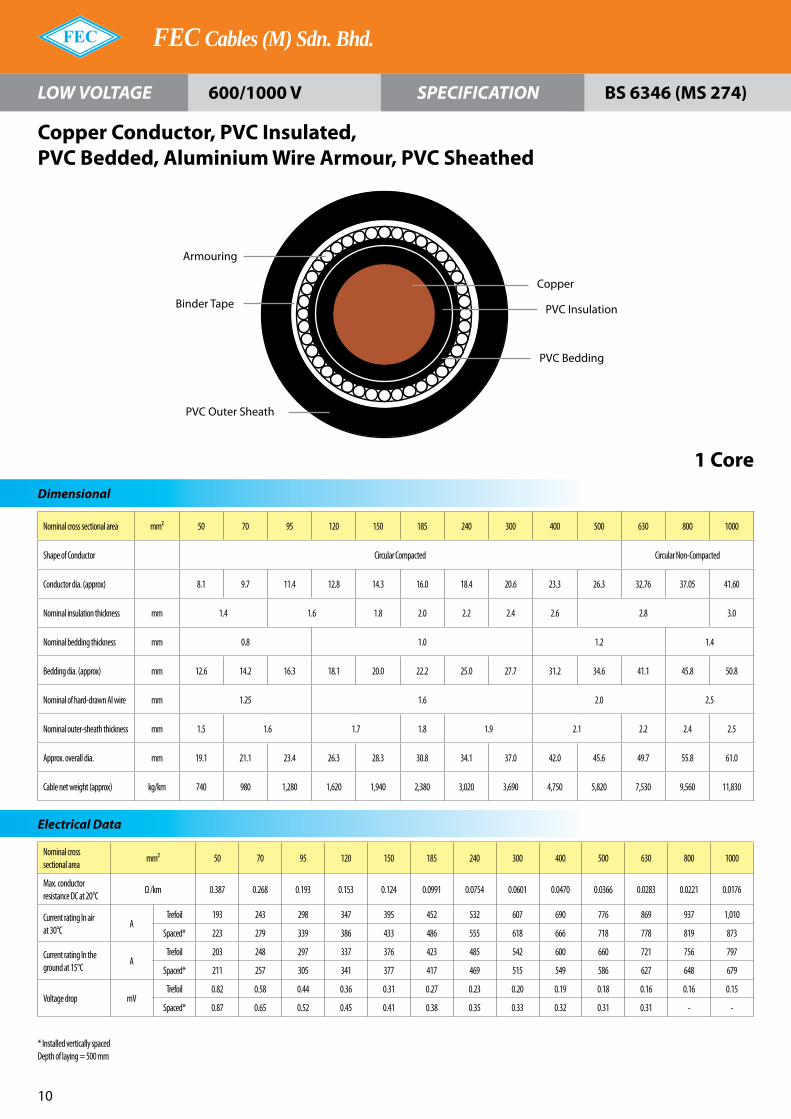
Nominal cross sectional area mm² 50 70 95 120 150 185 240 300 400 500 630 800 1000
Shape of Conductor Circular Compacted Circular Non-Compacted
Conductor dia. (approx) 8.1 9.7 11.4 12.8 14.3 16.0 18.4 20.6 23.3 26.3 32.76 37.05 41.60
Nominal insulation thickness mm 1.4 1.6 1.8 2.0 2.2 2.4 2.6 2.8 3.0
Nominal bedding thickness mm 0.8 1.0 1.2 1.4
Bedding dia. (approx) mm 12.6 14.2 16.3 18.1 20.0 22.2 25.0 27.7 31.2 34.6 41.1 45.8 50.8
Nominal of hard-drawn Al wire mm 1.25 1.6 2.0 2.5
Nominal outer-sheath thickness mm 1.5 1.6 1.7 1.8 1.9 2.1 2.2 2.4 2.5
Approx. overall dia. mm 19.1 21.1 23.4 26.3 28.3 30.8 34.1 37.0 42.0 45.6 49.7 55.8 61.0
Cable net weight (approx) kg/km 740 980 1,280 1,620 1,940 2,380 3,020 3,690 4,750 5,820 7,530 9,560 11,830
Nominal cross sectional area
mm² 50 70 95 120 150 185 240 300 400 500 630 800 1000
Max. conductor resistance DC at 20°C
Ω /km 0.387 0.268 0.193 0.153 0.124 0.0991 0.0754 0.0601 0.0470 0.0366 0.0283 0.0221 0.0176
Current rating In air at 30°C
ATrefoil 193 243 298 347 395 452 532 607 690 776 869 937 1,010
Spaced* 223 279 339 386 433 486 555 618 666 718 778 819 873
Current rating In the ground at 15°C
ATrefoil 203 248 297 337 376 423 485 542 600 660 721 756 797
Spaced* 211 257 305 341 377 417 469 515 549 586 627 648 679
Voltage drop mVTrefoil 0.82 0.58 0.44 0.36 0.31 0.27 0.23 0.20 0.19 0.18 0.16 0.16 0.15
Spaced* 0.87 0.65 0.52 0.45 0.41 0.38 0.35 0.33 0.32 0.31 0.31 - -
FEC Cables (M) Sdn. Bhd.
10
LOW VOLTAGE SPECIFICATION
Dimensional
1 Core
Electrical Data
Copper Conductor, PVC Insulated,PVC Bedded, Aluminium Wire Armour, PVC Sheathed
600/1000 V BS 6346 (MS 274)
Armouring
Binder Tape
PVC Outer Sheath
PVC Insulation
Copper
PVC Bedding
* Installed vertically spacedDepth of laying = 500 mm

Nominal cross sectional area
mm² 1.5 2.5 4 6 10 16 25 35 50 70 95 120 150 185 240 300 400
Shape of Conductor Circular Non-Compacted CC Shaped Stranded
Nominal insulation thickness
mm 0.6 0.7 0.8 0.8 1.0 1.2 1.4 1.6 1.8 2.0 2.2 2.4 2.6
Nominal bedding thickness
mm 0.8 1.0 1.2 1.4 1.6
Bedding dia. (approx) mm 7.3 8.6 10.3 11.4 13.4 15.4 16.3 17.7 20.5 23.1 26.9 28.9 31.7 35.7 40.1 44.7 49.1
Nominal of galvanized steel wire
mm 0.9 1.25 1.6 2.0 2.5
Nominal outer-sheath thickness
mm 1.4 1.5 1.6 1.7 1.8 1.9 2.1 2.2 2.3 2.4 2.5 2.7 2.9
Approx. overall dia. mm 12.3 13.6 15.1 16.5 20.1 21.9 23.0 24.9 27.8 30.4 35.5 38.0 41.3 46.4 51.2 56.4 61.9
Cable net weight (approx)
kg/km 260 320 410 490 740 930 1,300 1,570 1,970 2,490 3,480 4,080 4,810 6,200 7,730 9,260 11,330
ominal cross sectional area
mm² 1.5 2.5 4 6 10 16 25 35 50 70 95 120 150 185 240 300 400
Max. conductor resistance DC at 20°C
Ω /km 12.10 7.41 4.61 3.08 1.83 1.15 0.727 0.524 0.387 0.268 0.193 0.153 0.124 0.0991 0.0754 0.0601 0.0470
Current rating In air at 30°C
A 23 32 42 54 74 102 136 166 201 252 312 360 409 473 558 636 729
Current rating In the ground at 15°C
A 30 40 53 66 88 119 158 190 225 277 332 377 422 478 551 616 693
Voltage Drop (mV) 29 18 12 7.4 4.3 2.8 1.7 1.3 0.94 0.66 0.49 0.40 0.34 0.29 0.24 0.21 0.19
LOW VOLTAGE CABLES
11
LOW VOLTAGE SPECIFICATION
Dimensional
Electrical Data
Copper Conductor, PVC Insulated,PVC Bedded, Zinc-Coated Steel Wire Armour, PVC Sheathed
2 Core
600/1000 V BS 6346 (MS 274)
PVC Bedding
Armouring
PVC Outer Sheath
CopperPVC Insulation
Filler
Binder Tape

Nominal cross sectional area
mm² 1.5 2.5 4 6 10 16 25 35 50 70 95 120 150 185 240 300 400
Shape of Conductor Circular Non-Compacted CC Shaped Stranded
Nominal insulation thickness
mm 0.6 0.7 0.8 1.0 1.2 1.4 1.6 1.8 2.0 2.2 2.4 2.6
Nominal bedding thickness
mm 0.8 1.0 1.2 1.4 1.6
Bedding dia. (approx)
mm 7.8 9.1 10.9 12.2 14.3 16.4 18.6 20.6 23.8 27.2 31.6 33.7 37.0 41.6 47.2 52.0 57.6
Nominal of galva-nized steel wire
mm 0.9 1.25 1.6 2.0 2.5
Nominal outer-sheath thickness
mm 1.4 1.5 1.6 1.7 1.8 1.9 2.0 2.1 2.2 2.4 2.5 2.6 2.8 3.0
Approx. overall dia. mm 12.8 14.1 15.8 18.0 21.2 23.1 25.0 27.3 30.5 35.0 39.3 42.2 47.5 51.9 57.8 63.2 69.6
Cable net weight (approx)
kg/km 290 360 470 670 880 1,140 1,650 2,040 2,590 2,630 4,690 5,530 6,990 8,440 10,670 12,770 15,810
Nominal cross sectional area
mm² 1.5 2.5 4 6 10 16 25 35 50 70 95 120 150 185 240 300 400
Max. conductor resistance DC at 20°C
Ω /km 12.10 7.41 4.61 3.08 1.83 1.15 0.727 0.524 0.387 0.268 0.193 0.153 0.124 0.0991 0.0754 0.0601 0.0470
Current rating In air at 30°C
A 20 27 36 46 63 87 116 142 172 218 268 310 355 407 480 547 627
Current rating In the ground at 15°C
A 26 34 45 57 75 101 132 159 188 233 279 317 355 401 462 517 580
Voltage Drop (mV) 25 16 9.6 6.3 3.8 2.4 1.5 1.1 0.82 0.57 0.42 0.35 0.29 0.25 0.21 0.18 0.17
FEC Cables (M) Sdn. Bhd.
12
LOW VOLTAGE SPECIFICATION
Dimensional
Electrical Data
Copper Conductor, PVC Insulated, PVC Bedded,Zinc-Coated Steel Wire Armour, PVC Sheathed
3 Core
600/1000 V BS 6346 (MS 274)
PVC Bedding
Armouring
Copper
PVC Insulation
FillerBinder Tape
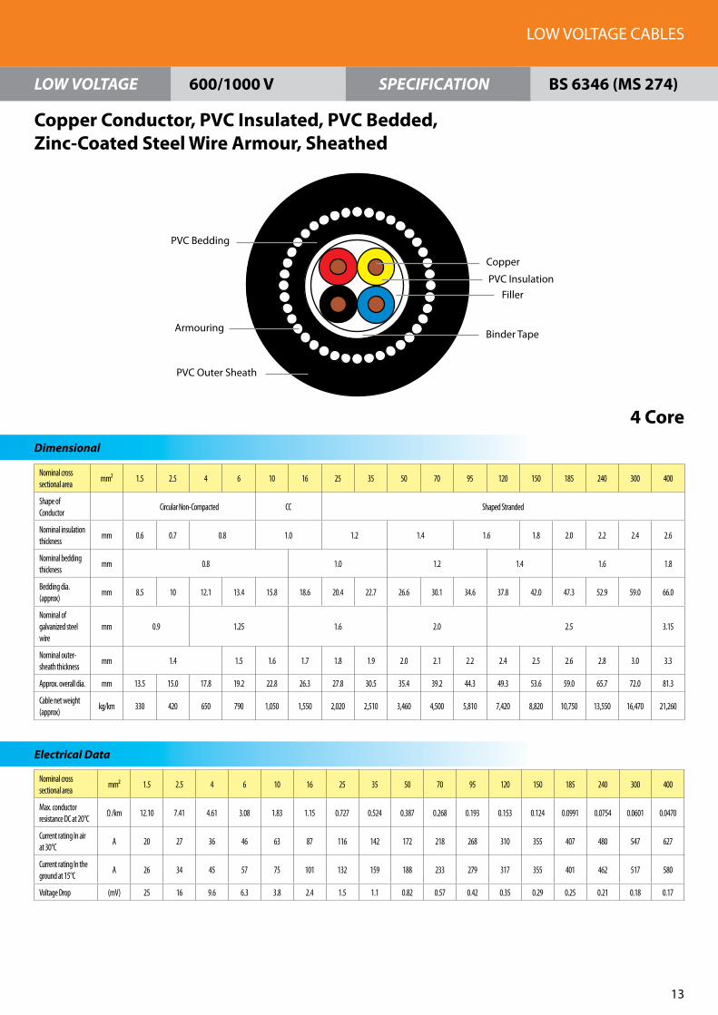
Nominal cross sectional area
mm² 1.5 2.5 4 6 10 16 25 35 50 70 95 120 150 185 240 300 400
Shape of Conductor
Circular Non-Compacted CC Shaped Stranded
Nominal insulation thickness
mm 0.6 0.7 0.8 1.0 1.2 1.4 1.6 1.8 2.0 2.2 2.4 2.6
Nominal bedding thickness
mm 0.8 1.0 1.2 1.4 1.6 1.8
Bedding dia. (approx)
mm 8.5 10 12.1 13.4 15.8 18.6 20.4 22.7 26.6 30.1 34.6 37.8 42.0 47.3 52.9 59.0 66.0
Nominal of galvanized steel wire
mm 0.9 1.25 1.6 2.0 2.5 3.15
Nominal outer-sheath thickness
mm 1.4 1.5 1.6 1.7 1.8 1.9 2.0 2.1 2.2 2.4 2.5 2.6 2.8 3.0 3.3
Approx. overall dia. mm 13.5 15.0 17.8 19.2 22.8 26.3 27.8 30.5 35.4 39.2 44.3 49.3 53.6 59.0 65.7 72.0 81.3
Cable net weight (approx)
kg/km 330 420 650 790 1,050 1,550 2,020 2,510 3,460 4,500 5,810 7,420 8,820 10,750 13,550 16,470 21,260
Nominal cross sectional area
mm² 1.5 2.5 4 6 10 16 25 35 50 70 95 120 150 185 240 300 400
Max. conductor resistance DC at 20°C
Ω /km 12.10 7.41 4.61 3.08 1.83 1.15 0.727 0.524 0.387 0.268 0.193 0.153 0.124 0.0991 0.0754 0.0601 0.0470
Current rating In air at 30°C
A 20 27 36 46 63 87 116 142 172 218 268 310 355 407 480 547 627
Current rating In the ground at 15°C
A 26 34 45 57 75 101 132 159 188 233 279 317 355 401 462 517 580
Voltage Drop (mV) 25 16 9.6 6.3 3.8 2.4 1.5 1.1 0.82 0.57 0.42 0.35 0.29 0.25 0.21 0.18 0.17
LOW VOLTAGE CABLES
13
LOW VOLTAGE SPECIFICATION
Dimensional
Electrical Data
Copper Conductor, PVC Insulated, PVC Bedded,Zinc-Coated Steel Wire Armour, Sheathed
4 Core
600/1000 V BS 6346 (MS 274)
PVC Bedding
Armouring
PVC Outer Sheath
Copper
PVC InsulationFiller
Binder Tape

Nominal cross sectional area(Phase)
mm² 25 35 50 70 95 120 150 185 240 300 300 400
Shape of Conductor(Phase) Shaped Stranded
Nominal insulation thickness(Phase)
mm 1.2 1.4 1.6 1.8 2.0 2.2 2.4 2.6
Nominal cross sectional area(RNC)
mm² 16 25 35 50 70 95 120 150 185
Shape of Conductor(RNC) Circular Non-Compacted
Nominal insulation thickness(RNC)
mm 1.0 1.2 1.4 1.6 1.8 2.0
Nominal bedding thickness mm 1.0 1.2 1.4 1.6 1.8
Bedding dia. (approx) mm 20.1 22.3 25.7 29.6 34.0 37.1 41.2 46.1 51.9 57.9 64.8
Nominal of galvanized steel wire
mm 1.6 2.0 2.5 3.15
Nominal outer-sheath thickness
mm 1.8 1.9 2.0 2.2 2.3 2.4 2.5 2.7 2.9 3.1
Approx. overall dia. mm 27.8 29.6 33.1 38.0 43.7 49.0 52.0 57.2 63.7 69.8 71.8 78.6
Cable net weight (approx) kg/km 1,920 2,310 2,980 4,150 5,350 6,890 8,050 9,810 12,330 14,840 15,190 19,270
Nominal cross sectional area
mm² 25 35 50 70 95 120 150 185 240 300 400
Max. conductor resistance DC at 20°C(Phase)
Ω /km 0.727 0.524 0.387 0.268 0.193 0.153 0.124 0.0991 0.0754 0.0601 0.0601 0.0470
Max. conductor resistance DC at 20°C(RNC)
Ω /km 1.15 1.15 0.727 0.524 0.387 0.268 0.268 0.193 0.153 0.124 0.0991 0.0991
FEC Cables (M) Sdn. Bhd.
1�
LOW VOLTAGE SPECIFICATION
Dimensional
Electrical Data
Copper Conductor, PVC Insulated, PVC Bedded, Zinc-Coated Steel Wire Armour, PVC Sheathed
3½ Core
600/1000 V MS 274 (BS 6346)
PVC Bedding
Armouring
PVC Outer Sheath
Copper (Phase)
PVC Insulation (Phase)
Filler
Binder Tape
Copper (RNC)PVC Insulation (RNC)
Note :- RNC = Reduced Neutral Conductor

No. of cores 5 6 7 8 9 10 11 12 13 14 15 16 17 18 19 20 21
Shape of Conductor Circular Stranded
Conductor dia. (approx.)
1.59
Nominal insulation thickness
mm 0.6
Nominal bedding thickness
mm 0.8
Bedding dia. (approx.) mm 10.2 11.1 12.0 12.9 14.0 14.5 14.8 15.3 15.7 16.1 16.6 17.0 17.6 17.9
Nominal of galvanized steel wire
mm 0.9 1.25
Nominal outer-sheath thickness
mm 1.4 1.5 1.6
Approx. overall dia. mm 14.4 15.3 16.4 18.0 19.1 19.6 20.1 20.6 21.0 21.4 21.9 22.3 22.9 23.2
Cable net weight (approx.)
kg/km 390 440 450 510 650 700 720 760 800 840 880 910 960 990 1,000 1,060 1,090
No. of cores 22 23 24 25 26 27 28 29 30 37 40 48 50
Shape of Conductor Circular Stranded
Conductor dia. (approx.) 1.59
Nominal insulation thickness mm 0.6
Nominal bedding thickness mm 1.0
Bedding dia. (approx.) mm 18.9 19.3 20.4 20.9 21.1 21.7 23.4 24.3 26.9
Nominal of galvanized steel wire mm 1.6
Nominal outer-sheath thickness mm 1.7 1.8 1.9
Approx. overall dia. mm 25.1 25.5 26.6 27.1 27.4 27.9 29.8 30.7 33.5
Cable net weight (approx.) kg/km 1,300 1,350 1,400 1,430 1,450 1,490 1,510 1,540 1,580 1,810 1,930 2,230 2,270
LOW VOLTAGE CABLES
15
LOW VOLTAGE SPECIFICATION
Dimensional
Copper Conductor, PVC Insulated, PVC Bedded, Zinc Coated Steel Wire Armour, PVC Sheathed Control
1.5 mm²
600/1000 V BS 6346 (MS 274)
PVC Outer Sheath
PVC Bedding
Armouring
Copper
PVC Insulation
Filler (If Necessary)
Binder Tape
Max. conductor resistance DC at 20°C = 12.10 Ω /kmCore Identification : Black numbers on white cores(for 2 cores up to 48 cores)For 50 cores, White insulation with number 1 - 28 and Red insulation with number 1 - 22

No. of cores 5 6 7 8 9 10 11 12 13 14 15 16 17 18 19 20 21
Shape of Conductor Circular Stranded
Conductor dia. (approx.) 2.01
Nominal insulation thickness mm 0.7
Nominal bedding thickness mm 0.8 1.0
Bedding dia. (approx.) mm 11.8 12.9 14.0 15.1 16.5 17.1 17.4 18.4 18.9 19.5 20.0 20.5 21.2 21.6
Nominal of galvanized steel wire mm 0.9 1.25 1.6
Nominal outer-sheath thickness mm 1.5 1.6 1.7 1.8
Approx. overall dia. mm 16.2 18.0 19.1 20.4 21.8 22.4 22.7 24.6 25.1 25.7 26.3 26.8 27.6 28.1
Cable net weight (approx.) kg/km 510 650 670 760 850 920 950 1,000 1,050 1,260 1,330 1,380 1,440 1,490 1,510 1,590 1,650
No. of cores 22 23 24 25 26 27 28 29 30 37 40 48 50
Shape of Conductor Circular Stranded
Conductor dia. (approx.) 2.01
Nominal insulation thickness
mm 0.7
Nominal bedding thickness
mm 1.0 1.2
Bedding dia. (approx.) mm 22.3 22.7 24.1 24.4 24.7 25.0 25.6 27.8 29.3 32.3
Nominal of galvanized steel wire
mm 1.6 2.0
Nominal outer-sheath thickness
mm 1.8 1.9 2.0 2.1
Approx. overall dia. mm 28.7 29.2 30.6 30.6 31.1 31.6 32.3 34.4 36.9 40.2
Cable net weight (approx.)
kg/km 1,710 1,770 1,860 1,890 1,920 1,980 2,010 2,070 2,140 2,460 2,880 3,330 3,400
FEC Cables (M) Sdn. Bhd.
16
LOW VOLTAGE SPECIFICATION
Dimensional
Copper Conductor, PVC Insulated, PVC Bedded,Zinc-Coated Steel Wire Armour, PVC Sheathed Control
2.5 mm²
600/1000 V BS 6346 (MS 274)
PVC Outer Sheath
PVC Bedding
Armouring
Copper
PVC Insulation
Filler (If Necessary)
Binder Tape
Electrical Data
Max. conductor resistance DC at 20°C = 7.41 Ω /kmCore Identification : Black numbers on white cores(for 2 cores up to 48 cores)For 50 cores, White insulation with number 1 - 28 and Red insulation with number 1 - 22

No. of cores 5 6 7 8 9 10 11 12 13 14 15 16 17 18 19 20 21
Shape of Conductor Circular Stranded
Conductor dia. (approx.) 2.55
Nominal insulation thickness
mm 0.8
Nominal bedding thickness
mm 0.8 1.0
Bedding dia. (approx.) mm 13.8 15.1 16.5 18.2 19.9 20.6 20.9 21.7 22.3 22.9 23.6 24.2 25.0 25.6
Nominal of galvanized steel wire
mm 1.25 1.6
Nominal outer-sheath thickness
mm 1.5 1.6 1.7 1.8 1.9 2.0
Approx. overall dia. mm 18.9 20.4 21.8 24.4 26.1 26.8 27.1 28.1 28.7 29.4 30.1 30.7 31.7 32.4
Cable net weight (approx.) kg/km 750 860 890 1,000 1,280 1,380 1,430 1,510 1,580 1,670 1,760 1,820 1,930 2,000 2,020 2,130 2,220
No. of cores 22 23 24 25 26 27 28 29 30 37 40 48 50
Shape of Conductor Circular Stranded
Conductor dia. (approx.) 2.55
Nominal insulation thickness
mm 0.8
Nominal bedding thickness
mm 1.0 1.2
Bedding dia. (approx.) mm 26.4 26.9 28.6 29.0 29.7 30.0 30.8 33.3 34.7 38.4
Nominal of galvanized steel wire
mm 1.6 2.0
Nominal outer-sheath thickness
mm 2.0 2.1 2.1 2.2
Approx. overall dia. mm 33.2 33.7 35.4 36.6 37.3 37.7 38.4 41.2 42.5 46.4
Cable net weight (approx.) kg/km 2,320 2,410 2,510 2,560 2,880 2,960 3,010 3,100 3,180 3,660 3,900 4,540 4,640
LOW VOLTAGE CABLES
17
LOW VOLTAGE SPECIFICATION
Dimensional
Copper Conductor, PVC Insulated, PVC Bedded,Zinc-Coated Steel Wire Armour, PVC Sheathed Control
4 mm²
600/1000 V BS 6346 (MS 274)
PVC Outer Sheath
PVC Bedding
Armouring
Copper
PVC Insulation
Filler (If Necessary)
Binder Tape
Max. conductor resistance DC at 20°C = 4.61 Ω /kmCore Identification : Black numbers on white cores(for 2 cores up to 48 cores)For 50 cores, White insulation with number 1 - 28 and Red insulation with number 1 - 22

Nominal cross sectional area
mm² 10 16 25 35 50 70 95 120 150 185 240 300 400 500 630 800 1000
Shape of Conductor Cicular Compacted Shaped Stranded
Conductor dia. (approx.)
3.7 4.7 5.9 7.0 8.1 9.7 11.4 12.8 14.3 16.0 18.4 20.6 23.3 26.3 32.76 37.05 41.6
Nominal insulation thickness
mm 1.0 1.2 1.4 1.6 1.8 2.0 2.2 2.4 2.6 2.8 3.0
Nominal sheath thickness
mm 1.4 1.5 1.5 1.6 1.7 1.8 1.9 2.0 2.1 2.2 2.3 2.5
Approx. overall dia. mm 9.0 10.0 12.0 13.0 14.5 16.0 18.5 20.0 22.0 24.5 27.5 30.5 33.5 37.0 44.0 48.5 54.0
Cable net. weight (approx.)
kg/km 170 230 340 440 580 800 1,080 1,330 1,630 2,040 2,640 3,300 4,170 5,200 6,770 8,520 10,700
Nominal cross sectional area
mm² 10 16 25 35 50 70 95 120 150 185 240 300 400 500 630 800 1000
Max. conductor resistance DC at 20°C
Ω /km 1.83 1.15 0.727 0.524 0.387 0.268 0.193 0.153 0.124 0.0991 0.0754 0.0601 0.0470 0.0366 0.0283 0.0221 0.0176
Max. conductor resistance 50Hz at 70°C
Ω /km 2.19 1.38 0.870 0.627 0.463 0.321 0.232 0.184 0.150 0.120 0.0926 0.0748 0.0600 0.0486 0.0395 0.0333 0.0290
Reactance at 50Hz Ω /km 0.115 0.107 0.102 0.0967 0.0950 0.0903 0.0887 0.0860 0.0855 0.0850 0.0836 0.0831 0.0819 0.0807 0.0773 0.0757 0.0753
Current rating In air at 40°C
A 52 69 90 115 140 175 220 255 295 340 405 470 550 635 760 865 970
Current rating In the ground at 25°C
A 75 98 125 150 175 215 260 295 330 375 435 490 555 630 720 795 870
FEC Cables (M) Sdn. Bhd.
18
LOW VOLTAGE SPECIFICATION
Dimensional
1 Core
Electrical Data Electrical Data
Copper Conductor, PVC Insulated, PVC Sheathed
600/1000 V IEC 60502-1
Copper
PVC Insulation
PVC Sheath

Nominal cross sectional area mm² 1.5 2.5 4 6 10 16 25 35 50 70 95 120 150 185 240 300 400
Shape of Conductor Circular Stranded CC Shaped Stranded
Nominal insulation thickness mm 0.8 1.0 1.2 1.4 1.6 1.8 2.0 2.2 2.4 2.6
Nominal sheath thickness mm 1.8 1.8 1.9 2.0 2.1 2.2 2.4 2.6 2.7 3.0
Approx. overall dia. mm 11.0 12.0 14.0 15.0 16.0 18.0 18.5 20.0 23.0 26.0 29.5 31.5 34.5 38.5 43.5 48.0 53.0
Cable net weight (approx.) kg/km 140 170 230 290 380 530 720 930 1,230 1,680 2,280 2,800 3,410 4,270 5,580 6,820 8,710
Nominal cross sectional area mm² 1.5 2.5 4 6 10 16 25 35 50 70 95 120 150 185 240 300 400
Max. conductor resistance DC at 20°C
Ω /km 12.10 7.41 4.61 3.08 1.83 1.15 0.727 0.524 0.387 0.268 0.193 0.153 0.124 0.0991 0.0754 0.0601 0.0470
Max. conductor resistance 50Hz at 70°C
Ω /km 14.5 8.87 5.52 3.69 2.19 1.38 0.870 0.627 0.464 0.321 0.232 0.185 0.150 0.121 0.0931 0.0755 0.0610
Reactance at 50Hz Ω /km 0.107 0.0994 0.0983 0.0928 0.0886 0.0834 0.0879 0.0847 0.0851 0.0812 0.0805 0.0786 0.0788 0.0789 0.0780 0.0778 0.0772
Current rating In air at 40°C A 20 26 35 45 61 81 100 125 150 190 235 275 310 360 430 490 565
Current rating In the ground at 25°C
A 30 39 51 64 85 110 135 165 195 240 290 330 370 415 480 545 610
LOW VOLTAGE CABLES
19
LOW VOLTAGE SPECIFICATION
Dimensional
Electrical Data
Copper Conductor, PVC Insulated, PVC Sheathed
2 Core
600/1000 V IEC 60502-1
PVC Sheath
Copper
PVC Insulation
Filler
Binder Tape
Note : CC = Circular Compacted

Nominal cross sectional area
mm² 1.5 2.5 4 6 10 16 25 35 50 70 95 120 150 185 240 300 400
Shape of Conductor Circular Stranded CC Shaped Stranded
Nominal insulation thickness
mm 0.8 1.0 1.2 1.4 1.6 1.8 2.0 2.2 2.4 2.6
Nominal sheath thickness
mm 1.8 1.8 2.0 2.1 2.2 2.3 2.5 2.7 2.9 3.1
Approx. overall dia. mm 11.5 12.5 14.5 16.0 17.0 19.0 21.0 23.0 26.0 29.5 34.0 36.5 39.5 44.5 50.5 55.5 61.5
Cable net weight (approx.)
kg/km 170 210 290 370 500 700 1,010 1,320 1,750 2,440 3,310 4,070 4,950 6,220 8,130 9,980 12,720
Nominal cross sectional area
mm² 1.5 2.5 4 6 10 16 25 35 50 70 95 120 150 185 240 300 400
Max. conductor resistance DC at 20°C
Ω /km 12.10 7.41 4.61 3.08 1.83 1.15 0.727 0.524 0.387 0.268 0.193 0.153 0.124 0.0991 0.0754 0.0601 0.0470
Max. conductor resis-tance 50Hz at 70°C
Ω /km 14.5 8.87 5.52 3.69 2.19 1.38 0.870 0.627 0.463 0.321 0.232 0.184 0.150 0.121 0.0928 0.0751 0.0603
Reactance at 50Hz Ω /km 0.107 0.0994 0.0983 0.0928 0.0886 0.0834 0.0879 0.0847 0.0851 0.0812 0.0805 0.0786 0.0788 0.0789 0.0780 0.0778 0.0772
Current rating In air at 40°C
A 17 22 30 38 52 69 90 110 135 170 210 245 280 325 385 445 510
Current rating In the ground at 25°C
A 25 33 43 54 72 94 120 140 170 205 250 280 315 360 415 465 525
FEC Cables (M) Sdn. Bhd.
20
LOW VOLTAGE SPECIFICATION
Dimensional
Electrical Data Electrical Data
Copper Conductor, PVC Insulated, PVC Sheathed
3 Core
600/1000 V IEC 60502-1
PVC Sheath
Copper
PVC Insulation
Filler
Binder Tape
Note : CC = Circular Compacted

Nominal cross sectional area mm² 1.5 2.5 4 6 10 16 25 35 50 70 95 120 150 185 240 300 400
Shape of Conductor Circular Stranded CC Shaped Stranded
Nominal insulation thickness
mm 0.8 1.0 1.2 1.4 1.6 1.8 2.0 2.2 2.4 2.6
Nominal sheath thickness mm 1.8 1.9 2.1 2.2 2.4 2.5 2.7 2.9 3.1 3.4
Approx. overall dia. mm 12.5 13.5 16.0 17.0 18.5 21.0 23.0 25.0 29.0 33.0 37.5 40.5 45.0 50.5 56.5 63.0 70.5
Cable net weight (approx.) kg/km 200 250 360 470 630 900 1,300 1,700 2,290 3,170 4,310 5,360 6,560 8,200 10,720 13,190 16,870
Nominal cross sectional area
mm² 1.5 2.5 4 6 10 16 25 35 50 70 95 120 150 185 240 300 400
Max. conductor resistance DC at 20°C
Ω /km 12.10 7.41 4.61 3.08 1.83 1.15 0.727 0.524 0.387 0.268 0.193 0.153 0.124 0.0991 0.0754 0.0601 0.0470
Max. conductor resis-tance 50Hz at 70°C
Ω /km 14.5 8.87 5.52 3.69 2.19 1.38 0.870 0.627 0.463 0.321 0.232 0.184 0.150 0.121 0.0928 0.0751 0.0603
Reactance at 50Hz Ω /km 0.107 0.0994 0.0983 0.0928 0.0886 0.0834 0.0879 0.0847 0.0851 0.0812 0.0805 0.0786 0.0788 0.0789 0.0780 0.0778 0.0772
Current rating In air at 40°C
A 17 22 30 38 52 69 90 110 135 170 210 245 280 325 385 445 510
Current rating In the ground at 25°C
A 25 33 43 54 72 94 120 140 170 205 250 280 315 360 415 465 525
LOW VOLTAGE CABLES
21
LOW VOLTAGE SPECIFICATION
Dimensional
Electrical Data
Copper Conductor, PVC Insulated, PVC Sheathed
4 Core
600/1000 V IEC 60502-1
PVC Sheath
Copper
PVC Insulation
Filler
Binder Tape
Note : CC = Circular Compacted

Nominal cross sectional area(Phase) mm² 25 35 50 70 95 120 150 185 240 300 400
Shape of Conductor(Phase) Shaped Stranded
Nominal insulation thickness(Phase) mm 1.2 1.2 1.4 1.4 1.6 1.6 1.8 2.0 2.2 2.4 2.6
Nominal cross sectional area(RNC) mm² 16 16 25 35 50 70 70 95 120 150 185
Shape of Conductor(RNC) Circular Compacted
Nominal insulation thickness(RNC) mm 1.0 1.0 1.2 1.2 1.4 1.4 1.4 1.6 1.6 1.8 2.0
Nominal sheath thickness mm 1.8 1.8 1.9 2.0 2.2 2.3 2.4 2.6 2.8 3.0 3.2
Approx. overall dia. mm 22.5 24.5 28.5 32.0 37.0 39.5 44.0 49.5 55.0 62.0 68.5
Cable net weight (approx) kg/km 1,200 1,520 2,070 2,840 3,870 4,860 5,810 7,350 9,520 11,730 14,910
Nominal cross sectional area mm² 25 35 50 70 95 120 150 185 240 300 400
Max. conductor resistance DC at 20°C(Phase)
Ω /km 0.727 0.524 0.387 0.268 0.193 0.153 0.124 0.0991 0.0754 0.0601 0.0470
Max. conductor resistance DC at 20°C(RNC)
Ω /km 1.15 1.15 0.727 0.524 0.387 0.268 0.268 0.193 0.153 0.124 0.0991
FEC Cables (M) Sdn. Bhd.
22
LOW VOLTAGE SPECIFICATION
Dimensional
Electrical Data Electrical Data
Copper Conductor, PVC Insulated, PVC Sheathed
3½ Core
600/1000 V IEC 60502-1
PVC Sheath
Copper (Phase)
PVC Insulation (Phase)
Filler
Binder Tape
Copper (RNC)PVC Insulation (RNC)
Note : RNC = Reduced Neutral Conductor

Nominal cross sectional area mm² 10 16 25 35 50 70 95 120 150 185 240 300 400 500 630 800 1000
Shape of Conductor Cicular Compacted Shaped Stranded
Conductor dia. (approx.) 3.7 4.7 5.9 7.0 8.1 9.7 11.4 12.8 14.3 16.0 18.4 20.6 23.3 26.3 32.76 37.05 41.6
Nominal insulation thickness mm 1.0 1.2 1.4 1.6 1.8 2.0 2.2 2.4 2.6 2.8 3.0
Nominal inner covering thickness
mm 1.0 1.2 1.4
Inner covering dia. (approx.) mm 7.9 8.9 10.5 11.6 13.0 14.6 16.7 18.1 20.0 22.2 25.0 27.7 31.2 34.6 41.1 45.8 50.8
Nominal of hard-drawn Al wire
mm 1.0 1.25 1.6 2.0 2.5
Nominal outer-sheath thickness
mm 1.8 1.9 2.0 2.1 2.2 2.4 2.5 2.7
Approx. overall dia. mm 13.5 14.5 16.0 17.5 19.5 21.0 23.0 25.0 27.0 29.5 32.5 36.0 39.5 43.5 50.5 56.0 61.5
Cable net. weight (approx.) kg/km 280 360 480 600 790 1,020 1,330 1,640 1,960 2,380 3,020 3,800 4,750 5,850 7,580 9,580 11,900
Nominal cross sectional area
mm² 10 16 25 35 50 70 95 120 150 185 240 300 400 500 630 800 1000
Max. conductor resistance DC at 20°C
Ω /km 1.83 1.15 0.727 0.524 0.387 0.268 0.193 0.153 0.124 0.0991 0.0754 0.0601 0.0470 0.0366 0.0283 0.0221 0.0176
Max. conductor resistance 50Hz at 70°C
Ω /km 2.19 1.38 0.870 0.627 0.463 0.321 0.232 0.184 0.149 0.120 0.0921 0.0743 0.0593 0.0478 0.0387 0.0323 0.0279
Reactance at 50Hz Ω /km 0.141 0.130 0.123 0.116 0.113 0.107 0.103 0.101 0.0988 0.0967 0.0941 0.0939 0.0923 0.0902 0.0859 0.0849 0.0837
Current rating In air at 40°C
A 57 73 100 125 150 190 235 275 310 360 430 500 580 670 795 910 1020
Current rating In the ground at 25°C
A 80 105 135 155 180 220 265 300 335 380 440 500 570 645 735 820 900
LOW VOLTAGE CABLES
23
LOW VOLTAGE SPECIFICATION
Dimensional
1 Core
Electrical Data
Copper Conductor, PVC Insulated, PVC Inner Covering, Aluminium Wire Armour, Sheathed
600/1000 V IEC 60502-1
Armouring
Binder Tape
PVC Outer Sheath
PVC Insulation
Copper
PVC Inner Covering

Nominal cross sectional area
mm² 1.5 2.5 4 6 10 16 25 35 50 70 95 120 150 185 240 300 400
Shape of Conductor Circular Stranded CC Shaped Stranded
Nominal insulation thickness
mm 0.8 1.0 1.2 1.4 1.6 1.8 2.0 2.2 2.4 2.6
Nominal inner covering thickness
mm 1.0 1.2 1.4 1.6
Inner covering dia. (approx.)
mm 8.7 9.6 11.5 12.6 13.8 15.8 16.3 17.7 20.5 23.1 26.9 28.9 31.7 35.7 40.1 44.7 49.1
Nominal of galvanized steel wire
mm 0.9 1.6 2.0 2.5
Nominal outer-sheath thickness
mm 1.8 1.9 2.0 2.2 2.3 2.4 2.6 2.8 2.9 3.2
Approx. overall dia. mm 14.0 15.0 17.0 18.0 19.0 21.0 23.0 24.5 27.5 31.0 35.5 37.5 40.5 46.0 50.5 55.5 60.5
Cable net weight (approx.)
kg/km 340 380 490 570 680 870 1,310 1,570 1,970 2,700 3,500 4,110 4,830 6,240 7,810 9,320 11,420
Nominal cross sectional area
mm² 1.5 2.5 4 6 10 16 25 35 50 70 95 120 150 185 240 300 400
Max. conductor resistance DC at 20°C
Ω /km 12.10 7.41 4.61 3.08 1.83 1.15 0.727 0.524 0.387 0.268 0.193 0.153 0.124 0.0991 0.0754 0.0601 0.0470
Max. conductor resis-tance 50Hz at 70°C
Ω /km 14.48 8.87 5.52 3.69 2.19 1.38 0.870 0.627 0.464 0.321 0.232 0.185 0.150 0.121 0.0931 0.0755 0.0610
Reactance at 50Hz Ω /km 0.107 0.0994 0.0983 0.0928 0.0886 0.0834 0.0879 0.0847 0.0851 0.0812 0.0805 0.0786 0.0788 0.0789 0.0780 0.0788 0.0772
Current rating In air at 40°C
A 21 28 37 47 63 84 105 130 155 200 245 280 320 370 435 495 560
Current rating In the ground at 25°C
A 30 39 51 64 85 110 140 165 195 240 290 330 365 415 475 535 595
FEC Cables (M) Sdn. Bhd.
2�
LOW VOLTAGE SPECIFICATION
Dimensional
Electrical Data Electrical Data
Copper Conductor, PVC Insulated, PVC Inner Covering, Zinc-Coated Steel Wire Armour, PVC Sheathed
2 Core
600/1000 V IEC 60502-1
CopperPVC Insulation
Filler
PVC Inner Covering
Armouring
PVC Outer SheathBinder Tape
Note : CC = Circular Compacted
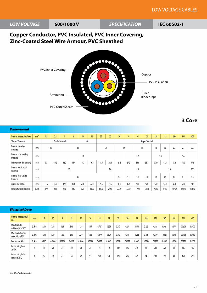
Nominal cross sectional area mm² 1.5 2.5 4 6 10 16 25 35 50 70 95 120 150 185 240 300 400
Shape of Conductor Circular Stranded CC Shaped Stranded
Nominal insulation thickness
mm 0.8 1.0 1.2 1.4 1.6 1.8 2.0 2.2 2.4 2.6
Nominal inner covering thickness
mm 1.0 1.2 1.4 1.6
Inner covering dia. (approx.) mm 9.3 10.2 12.2 13.4 14.7 16.8 18.6 20.6 23.8 27.2 31.6 33.7 37.0 41.6 47.2 52.0 57.6
Nominal of galvanized steel wire
mm 0.9 1.6 2.0 2.5 3.15
Nominal outer-sheath thickness
mm 1.8 2.0 2.1 2.2 2.3 2.5 2.7 2.9 3.1 3.4
Approx. overall dia. mm 14.5 15.5 17.5 19.0 20.0 22.0 25.5 27.5 31.0 35.5 40.0 42.0 47.0 52.0 58.0 63.0 70.5
Cable net weight (approx.) kg/km 370 430 560 660 820 1,070 1,670 2,050 2,610 3,650 4,720 5,560 7,010 8,490 10,750 12,870 16,680
Nominal cross sectional area
mm² 1.5 2.5 4 6 10 16 25 35 50 70 95 120 150 185 240 300 400
Max. conductor resistance DC at 20°C
Ω /km 12.10 7.41 4.61 3.08 1.83 1.15 0.727 0.524 0.387 0.268 0.193 0.153 0.124 0.0991 0.0754 0.0601 0.0470
Max. conductor resis-tance 50Hz at 70°C
Ω /km 14.48 8.87 5.52 3.69 2.19 1.38 0.870 0.627 0.463 0.321 0.232 0.185 0.150 0.121 0.0928 0.0751 0.0603
Reactance at 50Hz Ω /km 0.107 0.0994 0.0983 0.0928 0.0886 0.0834 0.0879 0.0847 0.0851 0.0812 0.0805 0.0786 0.0788 0.0789 0.0780 0.0778 0.0772
Current rating In air at 40°C
A 18 23 31 40 53 71 94 115 140 175 215 245 280 325 380 435 490
Current rating In the ground at 25°C
A 25 33 43 54 72 93 120 140 170 205 245 280 310 350 400 450 490
LOW VOLTAGE CABLES
25
LOW VOLTAGE SPECIFICATION
Dimensional
Electrical Data
Copper Conductor, PVC Insulated, PVC Inner Covering, Zinc-Coated Steel Wire Armour, PVC Sheathed
3 Core
600/1000 V IEC 60502-1
PVC Insulation
Filler
PVC Inner Covering
Armouring
PVC Outer Sheath
Copper
Binder Tape
Note : CC = Circular Compacted

Nominal cross sectional area
mm² 1.5 2.5 4 6 10 16 25 35 50 70 95 120 150 185 240 300 400
Shape of Conductor Circular Stranded CC Shaped Stranded
Nominal insulation thickness
mm 0.8 1.0 1.2 1.4 1.6 1.8 2.0 2.2 2.4 2.6
Nominal inner covering thickness
mm 1.0 1.2 1.4 1.6 1.8
Inner covering dia. (approx.)
mm 10.1 11.2 13.4 14.8 16.2 18.6 20.4 22.7 26.6 30.1 34.6 37.8 42.0 47.3 52.9 59.0 66.0
Nominal of galvanized steel wire
mm 0.9 1.6 2.0 2.5 3.15 3.15
Nominal outer-sheath thickness
mm 1.8 1.9 2.1 2.2 2.4 2.5 2.7 2.9 3.1 3.3 3.6
Approx. overall dia. mm 15.5 16.5 19.0 20.0 21.5 25.5 27.0 29.5 34.5 38.5 44.5 47.5 52.5 58.0 64.0 72.0 79.5
Cable net weight (approx.)
kg/km 430 500 650 790 980 1,560 2,030 2,520 3,480 4,520 6,220 7,440 8,880 10,830 13,650 17,240 21,390
Nominal cross sectional area
mm² 1.5 2.5 4 6 10 16 25 35 50 70 95 120 150 185 240 300 400
Max. conductor resistance DC at 20°C
Ω /km 12.10 7.41 4.61 3.08 1.83 1.15 0.727 0.524 0.387 0.268 0.193 0.153 0.124 0.0991 0.0754 0.0601 0.0470
Max. conductor resis-tance 50Hz at 70°C
Ω /km 14.48 8.87 5.52 3.69 2.19 1.38 0.870 0.627 0.463 0.321 0.232 0.184 0.150 0.121 0.0928 0.0751 0.0603
Reactance at 50Hz Ω /km 0.107 0.0994 0.0983 0.0928 0.0886 0.0834 0.0879 0.0847 0.0851 0.0812 0.0805 0.0786 0.0788 0.0789 0.0780 0.0778 0.0772
Current rating In air at 40°C
A 18 23 31 40 53 71 94 115 140 175 215 245 280 325 380 435 490
Current rating In the ground at 25°C
A 25 33 43 54 72 93 120 140 170 205 245 280 310 350 400 450 490
FEC Cables (M) Sdn. Bhd.
26
LOW VOLTAGE SPECIFICATION
Dimensional
Electrical Data Electrical Data
Copper Conductor, PVC Insulated, PVC Inner Covering, Zinc-Coated Steel Wire Armour, PVC Sheathed
4 Core
600/1000 V IEC 60502-1
PVC Inner Covering
Armouring
PVC Outer Sheath
CopperPVC Insulation
Filler
Binder Tape
Note : CC = Circular Compacted

Nominal cross sectional area(Phase) mm² 25 35 50 70 95 120 150 185 240 300 400
Shape of Conductor(Phase) Shaped Stranded
Nominal insulation thickness(Phase) mm 1.2 1.2 1.4 1.4 1.6 1.6 1.8 2.0 2.2 2.4 2.6
Nominal cross sectional area(RNC) mm² 16 16 25 35 50 70 70 95 120 150 185
Shape of Conductor(RNC) Circular Compacted
Nominal insulation thickness(RNC) mm 1.0 1.0 1.2 1.2 1.4 1.4 1.4 1.6 1.6 1.8 2.0
Nominal inner covering thickness mm 1.0 1.0 1.2 1.2 1.2 1.4 1.4 1.4 1.6 1.6 1.8
Inner covering dia. (approx) mm 20.1 22.3 26.1 29.6 34.0 37.1 41.2 46.1 51.9 57.9 64.8
Nominal of galvanized steel wire mm 1.6 1.6 2.0 2.0 2.0 2.5 2.5 2.5 2.5 2.5 3.15
Nominal outer-sheath thickness mm 1.8 1.9 2.0 2.1 2.3 2.5 2.6 2.7 2.9 3.1 3.4
Approx. overall dia. mm 27.0 29.5 34.0 37.5 42.5 47.0 51.5 56.5 62.5 69.0 77.5
Cable net weight (approx) kg/km 1,920 2,320 3,250 4,160 5,360 6,920 8,080 9,860 12,390 14,900 19,370
Nominal cross sectional area mm² 25 35 50 70 95 120 150 185 240 300 400
Max. conductor resistance DC at 20°C(Phase) Ω /km 0.727 0.524 0.387 0.268 0.193 0.153 0.124 0.0991 0.0754 0.0601 0.0470
Max. conductor resistance DC at 20°C(RNC) Ω /km 1.15 1.15 0.727 0.524 0.387 0.268 0.268 0.193 0.153 0.124 0.0991
LOW VOLTAGE CABLES
27
LOW VOLTAGE SPECIFICATION
Dimensional
Electrical Data
Copper Conductor, PVC Insulated, PVC Inner Covering, Zinc-Coated Steel Wire Armour, PVC Sheathed
3½ Core
600/1000 V IEC 60502-1
PVC Inner Covering
Armouring
PVC Outer Sheath
Copper (Phase)
PVC Insulation (Phase)
Filler
Binder Tape
Copper (RNC)PVC Insulation (RNC)
Note : RNC = Reduced Neutral Conductor

Nominal cross sectional area
mm² 10 16 25 35 50 70 95 120 150 185 240 300 400 500 630 800 1000
Shape of Conductor Cicular Compacted Circular Stranded
Conductor dia. (approx.) 3.7 4.7 5.9 7.0 8.1 9.7 11.4 12.8 14.3 16.0 18.4 20.6 23.3 26.3 32.76 37.05 41.6
Nominal insulation thickness
mm 0.7 0.9 1.0 1.1 1.2 1.4 1.6 1.7 1.8 2.0 2.2 2.4 2.6 2.8
Nominal outer-sheath thickness
mm 1.4 1.5 1.6 1.7 1.8 1.9 2.0 2.2 2.3 2.4
Approx. overall dia. mm 8.5 9.5 11.0 12.5 13.5 15.5 17.5 19.0 21.0 23.0 26.0 28.5 32.0 35.5 43.0 48.0 53.0
Cable net. weight (approx.)
kg/km 150 210 310 410 540 750 1,020 1,270 1,560 1,930 2,510 3,120 3,970 4,980 6,510 8,260 10,350
Nominal cross sectional area
mm² 10 16 25 35 50 70 95 120 150 185 240 300 400 500 630 800 1000
Max. conductor resistance DC at 20°C
Ω /km 1.83 1.15 0.727 0.524 0.387 0.268 0.193 0.153 0.124 0.0991 0.0754 0.0601 0.0470 0.0366 0.0283 0.0221 0.0176
Max. conductor resis-tance 50Hz at 90°C
Ω /km 2.33 1.47 0.927 0.669 0.494 0.342 0.247 0.196 0.160 0.128 0.0988 0.0801 0.0643 0.0521 0.0428 0.0363 0.0317
Reactance at 50Hz Ω /km 0.110 0.102 0.0979 0.0934 0.0905 0.0870 0.0851 0.0837 0.0837 0.0826 0.0812 0.0801 0.0792 0.0785 0.0776 0.0759 0.0749
Current rating In air at 40°C
A 68 91 120 150 185 235 290 340 390 455 545 630 735 850 985 1150 1280
Current rating In the ground at 25°C
A 89 115 145 170 205 250 295 340 380 430 495 560 635 715 800 895 970
Short circuit current for 1 sec.
kA 1.52 2.41 3.72 5.18 7.36 10.2 13.8 17.4 21.8 26.8 34.7 43.4 57.7 72.1 90.8 115.2 143.9
FEC Cables (M) Sdn. Bhd.
28
LOW VOLTAGE SPECIFICATION
Dimensional
1 Core
Electrical Data Electrical Data
Copper Conductor, XLPE Insulated, PVC Sheathed
600/1000 V IEC 60502-1
Copper
XLPE Insulation
PVC Sheath
Core Identification : Neutral

Nominal cross sectional area
mm² 1.5 2.5 4 6 10 16 25 35 50 70 95 120 150 185 240 300 400
Shape of Conductor Circular Stranded CC Shaped Stranded
Conductor dia. (approx.) 1.59 2.01 2.55 3.12 3.7 4.7 4.5 5.2 6.1 7.4 8.7 9.7 10.7 12.0 13.8 15.4 17.2
Nominal insulation thickness
mm 0.7 0.9 1.0 1.1 1.2 1.4 1.6 1.7 1.8 2.0
Nominal sheath thickness mm 1.8 1.8 2.0 2.1 2.2 2.3 2.5 2.7 2.9
Approx. overall dia. mm 10.0 11.0 12.0 13.0 14.5 16.5 17.0 18.5 20.5 24.0 27.0 29.5 32.5 36.0 40.5 44.5 49.5
Cable net weight (approx.) kg/km 110 140 180 230 330 460 640 830 1,090 1,520 2,060 2,570 3,150 3,920 5,130 6,290 8,050
Nominal cross sectional area
mm² 1.5 2.5 4 6 10 16 25 35 50 70 95 120 150 185 240 300 400
Max. conductor resistance DC at 20°C
Ω /km 12.10 7.41 4.61 3.08 1.83 1.15 0.727 0.524 0.387 0.268 0.193 0.153 0.124 0.0991 0.0754 0.0601 0.0470
Max. conductor resis-tance 50Hz at 90°C
Ω /km 15.43 9.45 5.88 3.93 2.33 1.47 0.927 0.669 0.494 0.342 0.247 0.196 0.160 0.128 0.0987 0.0798 0.0640
Reactance at 50Hz Ω /km 0.103 0.0961 0.0899 0.0853 0.0785 0.0771 0.0776 0.0752 0.0744 0.0731 0.0713 0.0713 0.0719 0.0720 0.0713 0.0707 0.0704
Current rating In air at 40°C
A 25 32 44 57 79 100 135 165 205 255 315 370 420 485 580 665 770
Current rating In the ground at 25°C
A 35 45 60 76 98 125 160 195 230 285 340 385 435 490 565 640 725
Short circuit current for 1 sec.
kA 0.255 0.409 0.636 0.935 1.52 2.41 3.72 5.18 7.36 10.2 13.8 17.4 21.8 26.8 34.7 43.4 57.7
LOW VOLTAGE CABLES
29
LOW VOLTAGE SPECIFICATION
Dimensional
Electrical Data
Copper Conductor, XLPE Insulated, PVC Sheathed
2 Core
600/1000 V IEC 60502-1
PVC Sheath
XLPE Insulation
Copper
Filler
Binder Tape
Note : CC = Circular Compacted

Nominal cross sectional area
mm² 1.5 2.5 4 6 10 16 25 35 50 70 95 120 150 185 240 300 400
Shape of Conductor Circular Stranded CC Shaped Stranded
Conductor dia. (approx.) 1.59 2.01 2.55 3.12 3.7 4.7 5.2 6.2 7.2 8.7 10.4 11.4 12.4 14.1 16.2 18.0 20.3
Nominal insulation thickness
mm 0.7 0.9 1.0 1.1 1.2 1.4 1.6 1.7 1.8 2.0
Nominal outer-sheath thickness
mm 1.8 1.9 2.0 2.1 2.3 2.4 2.6 2.8 3.1
Approx. overall dia. mm 10.5 11.5 12.5 14.0 15.5 17.5 19.0 21.5 24.0 27.5 31.5 34.0 37.5 42.0 47.0 51.5 58.0
Cable net. weight (approx.)
kg/km 130 170 230 300 430 620 900 1,190 1,570 2,230 3,010 3,760 4,610 5,760 7,540 9,240 11,880
Nominal cross sectional area
mm² 1.5 2.5 4 6 10 16 25 35 50 70 95 120 150 185 240 300 400
Max. conductor resistance DC at 20°C
Ω /km 12.10 7.41 4.61 3.08 1.83 1.15 0.727 0.524 0.387 0.268 0.193 0.153 0.124 0.0991 0.0754 0.0601 0.0470
Max. conductor resis-tance 50Hz at 90°C
Ω /km 15.43 9.45 5.88 3.93 2.33 1.47 0.927 0.669 0.494 0.343 0.248 0.197 0.160 0.129 0.0996 0.0809 0.0653
Reactance at 50Hz Ω /km 0.103 0.0961 0.0899 0.0853 0.0785 0.0771 0.0776 0.0752 0.0744 0.0731 0.0713 0.0713 0.0719 0.0720 0.0713 0.0707 0.0704
Current rating In air at 40°C
A 21 26 37 48 65 87 115 140 175 220 270 315 360 420 495 570 655
Current rating In the ground at 25°C
A 28 37 48 60 81 105 135 160 190 235 285 325 365 410 475 535 605
Short circuit current for 1 sec.
kA 0.255 0.409 0.636 0.935 1.52 2.41 3.72 5.18 7.36 10.2 13.8 17.4 21.8 26.8 34.7 43.4 57.7
FEC Cables (M) Sdn. Bhd.
30
LOW VOLTAGE SPECIFICATION
Dimensional
Electrical Data Electrical Data
Copper Conductor, XLPE Insulated, PVC Sheathed
3 Core
600/1000 V IEC 60502-1
XLPE Insulation
PVC Sheath
Copper
Filler
Binder Tape
Note : CC = Circular Compacted

Nominal cross sectional area
mm² 1.5 2.5 4 6 10 16 25 35 50 70 95 120 150 185 240 300 400
Shape of Conductor Circular Stranded CC Shaped Stranded
Conductor dia. (approx.) 1.59 2.01 2.55 3.12 3.7 4.7 5.9 7.0 8.1 9.8 11.5 12.8 14.4 16.2 18.4 20.8 23.5
Nominal insulation thickness
mm 0.7 0.9 1.0 1.1 1.2 1.4 1.6 1.7 1.8 2.0
Nominal sheath thickness mm 1.8 1.8 1.9 2.0 2.1 2.3 2.4 2.6 2.8 3.0 3.3
Approx. overall dia. mm 11.5 12.5 13.5 15.0 17.0 19.5 21.0 23.5 26.5 30.5 34.5 38.0 42.5 47.5 53.0 59.0 66.5
Cable net. weight (approx.)
kg/km 160 210 280 380 550 800 1,160 1,550 2,060 2,910 3,940 4,970 6,090 7,620 9,980 12,250 15,740
Nominal cross sectional area
mm² 1.5 2.5 4 6 10 16 25 35 50 70 95 120 150 185 240 300 400
Max. conductor resistance DC at 20°C
Ω /km 12.10 7.41 4.61 3.08 1.83 1.15 0.727 0.524 0.387 0.268 0.193 0.153 0.124 0.0991 0.0754 0.0601 0.0470
Max. conductor resis-tance 50Hz at 90°C
Ω /km 15.43 9.45 5.88 3.93 2.33 1.47 0.927 0.669 0.494 0.343 0.248 0.197 0.160 0.129 0.0996 0.0809 0.0653
Reactance at 50Hz Ω /km 0.103 0.0961 0.0899 0.0853 0.0785 0.0771 0.0776 0.0752 0.0744 0.0731 0.0713 0.0713 0.0719 0.0720 0.0713 0.0707 0.0704
Current rating In air at 40°C
A 21 26 37 48 65 87 115 140 175 220 270 315 360 420 495 570 655
Current rating In the ground at 25°C
A 28 37 48 60 81 105 135 160 190 235 285 325 365 410 475 535 605
Short circuit current for 1 sec.
kA 0.255 0.409 0.636 0.935 1.52 2.41 3.72 5.18 7.36 10.2 13.8 17.4 21.8 26.8 34.7 43.4 57.7
LOW VOLTAGE CABLES
31
LOW VOLTAGE SPECIFICATION
Dimensional
Electrical Data
Copper Conductor, XLPE Insulated, PVC Sheathed
4 Core
600/1000 V IEC 60502-1
FillerPVC Sheath
Copper
XLPE Insulation
Binder Tape
Note : CC = Circular Compacted

Nominal cross sectional area(Phase)
mm² 25 35 50 70 95 120 150 185 240 300 400
Shape of Conductor(Phase) Shaped Stranded
Nominal insulation thickness(Phase)
mm 0.9 0.9 1.0 1.1 1.1 1.2 1.4 1.6 1.7 1.8 2.0
Nominal cross sectional area(RNC)
mm² 16 16 25 35 50 70 70 95 120 150 185
Shape of Conductor(RNC) Circular Compacted
Nominal insulation thickness(RNC)
mm 0.7 0.7 0.9 0.9 1.0 1.1 1.1 1.1 1.2 1.4 1.6
Nominal sheath thickness mm 1.8 1.8 1.8 1.9 2.1 2.2 2.3 2.5 2.7 2.9 3.1
Approx. overall dia. mm 20.5 23.0 25.5 30.0 34.0 37.0 41.5 46.5 52.0 58.0 64.5
Cable net weight (approx) kg/km 1,080 1,380 1,850 2,600 3,530 4,500 5,380 6,810 8,870 10,890 13,910
Nominal cross sectional area mm² 25 35 50 70 95 120 150 185 240 300 400
Max. conductor resistance DC at 20°C(Phase)
Ω /km 0.727 0.524 0.387 0.268 0.193 0.153 0.124 0.0991 0.0754 0.0601 0.0470
Max. conductor resistance DC at 20°C(RNC)
Ω /km 1.15 1.15 0.727 0.524 0.387 0.268 0.268 0.193 0.153 0.124 0.0991
FEC Cables (M) Sdn. Bhd.
32
LOW VOLTAGE SPECIFICATION
Dimensional
Electrical Data
Copper Conductor, XLPE Insulated, PVC Sheathed
3½ Core
600/1000 V IEC 60502-1
PVC Sheath
Copper (Phase)
XLPE Insulation (Phase)
Filler
Binder Tape
Copper (RNC)
XLPE Insulation (RNC)
Note : RNC = Reduced Neutral Conductor

Nominal cross sectional area
mm² 10 16 25 35 50 70 95 120 150 185 240 300 400 500 630 800 1000
Shape of Conductor Circular Compacted Circular Stranded
Conductor dia. (approx.)
3.7 4.7 5.9 7.0 8.1 9.7 11.4 12.8 14.3 16.0 18.4 20.6 23.3 26.3 32.76 37.05 41.6
Nominal insulation thickness
mm 0.7 0.7 0.9 1.0 1.1 1.2 1.4 1.6 1.7 1.8 2.0 2.2 2.4 2.6 2.8
Nominal inner cover-ing thickness
mm 1.0 1.2 1.4
Inner covering dia. (approx.)
mm 7.3 8.0 9.7 10.8 12.1 13.9 15.6 17.2 19.2 21.3 23.9 26.3 29.9 33.3 40.3 45.4 50.3
Nominal of hard-drawn Al wire
mm 1.0 1.6 2.0 2.5
Nominal outer-sheath thickness
mm 1.8 1.9 2.1 2.2 2.3 2.5 2.7
Approx. overall dia. mm 13.0 14.0 15.5 16.5 18.0 20.0 21.5 24.5 26.5 28.5 31.0 33.5 38.5 42.0 49.5 55.5 61.0
Cable net. weight (approx.)
kg/km 260 330 450 560 710 940 1,210 1,560 1,870 2,270 2,890 3,520 4,550 5,620 7,290 9,320 11,580
Nominal cross sectional area
mm² 10 16 25 35 50 70 95 120 150 185 240 300 400 500 630 800 1000
Max. conductor resistance DC at 20°C
Ω /km 1.83 1.15 0.727 0.524 0.387 0.268 0.193 0.153 0.124 0.0991 0.0754 0.0601 0.0470 0.0366 0.0283 0.0221 0.0176
Max. conductor resistance 50Hz at 90°C
Ω /km 2.33 1.47 0.927 0.668 0.494 0.342 0.247 0.196 0.159 0.128 0.0982 0.0793 0.0632 0.0509 0.0415 0.0347 0.0300
Reactance at 50Hz Ω /km 0.137 0.126 0.119 0.113 0.113 0.107 0.102 0.101 0.0999 0.0975 0.0946 0.0920 0.0923 0.0903 0.0878 0.0863 0.0847
Current rating In air at 40°C
A 77 100 135 165 200 255 310 365 415 480 570 650 760 870 995 1150 1250
Current rating In the ground at 25°C
A 90 115 150 170 205 250 300 340 385 435 500 565 635 715 800 890 940
Short circuit current for 1 sec.
kA 1.52 2.41 3.72 5.18 7.36 10.2 13.8 17.4 21.8 26.8 34.7 43.4 57.7 72.1 90.8 115.2 143.9
LOW VOLTAGE CABLES
33
LOW VOLTAGE SPECIFICATION
Dimensional
Electrical Data
Copper Conductor, XLPE Insulated, PVC Sheathed, PVC Bedded,Aluminium Wire Armour, PVC Sheathed
1 Core
600/1000 V IEC 60502-1
Armouring
Binder Tape
PVC Outer Sheath
XLPE Insulation
Copper
PVC Inner Covering
Core Identification : Neutral

Nominal cross sectional area mm² 1.5 2.5 4 6 10 16 25 35 50 70 95 120 150 185 240 300 400
Shape of Conductor Circular Stranded CC Shaped Stranded
Conductor dia. (approx.) 1.59 2.01 2.55 3.12 3.7 4.7 4.5 5.2 6.1 7.4 8.7 9.7 10.7 12.0 13.8 15.4 17.2
Nominal insulation thickness mm 0.7 0.9 1.0 1.1 1.2 1.4 1.6 1.7 1.8 2.0
Nominal inner covering thickness
mm 1.0 1.2 1.4 1.6
Inner covering dia. (approx.) mm 8.9 9.7 10.8 11.9 13.5 15.5 15.9 17.3 19.5 22.6 25.6 28.0 30.8 34.6 38.6 42.6 47.0
Nominal of galvanized steel wire
mm 0.9 1.25 1.6 2.0 2.5
Nominal outer-sheath thickness
mm 1.8 2.0 2.1 2.2 2.3 2.5 2.7 2.8 3.1
Approx. overall dia. mm 14.0 14.5 16.5 17.5 19.0 21.0 22.5 23.5 26.0 29.5 33.5 36.0 39.0 44.5 48.5 53.0 58.0
Cable net weight (approx.) kg/km 320 370 500 590 730 920 1,210 1,460 1,790 2,360 3,220 3,850 4,550 5,870 7,320 8,720 10,750
Nominal cross sectional area
mm² 1.5 2.5 4 6 10 16 25 35 50 70 95 120 150 185 240 300 400
Max. conductor resistance DC at 20°C
Ω /km 12.10 7.41 4.61 3.08 1.83 1.15 0.727 0.524 0.387 0.268 0.193 0.153 0.124 0.0991 0.0754 0.0601 0.0470
Max. conductor resistance 50Hz at 90°C
Ω /km 15.43 9.45 5.88 3.93 2.33 1.47 0.927 0.669 0.494 0.342 0.247 0.196 0.160 0.128 0.0987 0.0798 0.0640
Reactance at 50Hz Ω /km 0.103 0.0961 0.0899 0.0853 0.0780 0.0767 0.0770 0.0746 0.0738 0.0726 0.0808 0.0709 0.0719 0.0720 0.0713 0.0707 0.0704
Current rating In air at 40°C A 29 38 45 58 79 105 140 170 210 260 320 370 425 485 575 650 745
Current rating In the ground at 25°C
A 33 45 59 75 98 125 160 195 230 280 335 380 425 480 555 620 695
Short circuit current for 1 sec.
kA 0.255 0.409 0.636 0.935 1.52 2.41 3.72 5.18 7.36 10.2 13.8 17.4 21.8 26.8 34.7 43.4 57.7
FEC Cables (M) Sdn. Bhd.
3�
LOW VOLTAGE SPECIFICATION
Dimensional
Electrical Data
Copper Conductor, XLPE Insulated, PVC Sheathed, PVC Bedded,Zinc-Coated Steel Wire Armour, PVC Sheathed
2 Core
600/1000 V IEC 60502-1
PVC Inner Covering
Armouring
PVC Outer Sheath
CopperXLPE Insulation
FillerBinder Tape
Note : CC = Circular Compacted

Nominal cross sectional area mm² 1.5 2.5 4 6 10 16 25 35 50 70 95 120 150 185 240 300 400
Shape of Conductor Circular Stranded CC Shaped Stranded
Conductor dia. (approx.) 1.59 2.01 2.55 3.12 3.7 4.7 4.5 6.2 7.2 8.7 10.4 11.4 12.4 14.1 16.2 18.0 20.3
Nominal insulation thickness mm 0.7 0.9 1.0 1.1 1.2 1.4 1.6 1.7 1.8 2.0
Nominal inner covering thickness
mm 1.0 1.2 1.4 1.6
Inner covering dia. (approx.) mm 9.4 10.3 11.4 12.7 14.3 16.5 18.0 20.1 22.6 26.6 30.1 32.6 35.9 40.3 45.4 49.6 55.2
Nominal of galvanized steel wire
mm 0.9 1.25 1.6 2.0 2.5
Nominal outer-sheath thickness
mm 1.8 1.9 2.0 2.2 2.3 2.5 2.6 2.8 3.0 3.2
Approx. overall dia. mm 14.5 16.0 17.0 18.5 20.0 22.0 24.5 26.5 29.0 34.0 38.0 41.0 45.5 50.0 55.5 60.5 66.5
Cable net. weight (approx.) kg/km 360 480 570 680 860 1,110 1,550 1,920 2,400 3,420 4,390 5,230 6,640 8,020 10,140 12,080 15,020
Nominal cross sectional area
mm² 1.5 2.5 4 6 10 16 25 35 50 70 95 120 150 185 240 300 400
Max. conductor resistance DC at 20°C
Ω /km 12.10 7.41 4.61 3.08 1.83 1.15 0.727 0.524 0.387 0.268 0.193 0.153 0.124 0.0991 0.0754 0.0601 0.0470
Max. conductor resis-tance 50Hz at 90°C
Ω /km 15.43 9.45 5.88 3.93 2.33 1.47 0.927 0.669 0.494 0.343 0.248 0.197 0.160 0.129 0.0996 0.0809 0.0653
Reactance at 50Hz Ω /km 0.103 0.0961 0.0899 0.0853 0.0780 0.0767 0.0770 0.0746 0.0738 0.0726 0.0808 0.0709 0.0719 0.0720 0.0713 0.0707 0.0704
Current rating In air at 40°C
A 21 27 38 49 65 89 120 145 175 225 275 315 365 420 490 555 635
Current rating In the ground at 25°C
A 28 37 48 60 81 105 135 160 190 235 280 320 355 405 465 515 580
Short circuit current for 1 sec.
kA 0.255 0.409 0.636 0.935 1.52 2.41 3.72 5.18 7.36 10.2 13.8 17.4 21.8 26.8 34.7 43.4 57.7
LOW VOLTAGE CABLES
35
LOW VOLTAGE SPECIFICATION
Dimensional
Electrical Data
Copper Conductor, XLPE Insulated, PVC Bedded,Zinc-Coated Steel Wire Armour, PVC Sheathed
3 Core
600/1000 V IEC 60502-1
XLPE Insulation
PVC Inner Covering
Armouring
PVC Outer Sheath
Copper
FillerBinder Tape
Note : CC = Circular Compacted

Nominal cross sectional area mm² 1.5 2.5 4 6 10 16 25 35 50 70 95 120 150 185 240 300 400
Shape of Conductor Circular Stranded CC Shaped Stranded
Conductor dia. (approx.) 1.59 2.01 2.55 3.12 3.7 4.7 5.9 7.0 8.1 9.8 11.5 12.8 14.4 16.2 18.4 20.8 23.5
Nominal insulation thickness mm 0.7 0.9 1.0 1.1 1.2 1.4 1.6 1.7 1.8 2.0
Nominal inner covering thickness
mm 1.0 1.2 1.4 1.6 1.8
Inner covering dia. (approx.) mm 10.2 11.2 12.5 13.9 15.8 18.2 19.9 22.2 24.9 29.5 33.1 36.6 40.9 45.6 51.1 56.6 63.5
Nominal of galvanized steel wire
mm 0.9 1.25 1.6 2.0 2.5 3.15
Nominal outer-sheath thickness
mm 1.8 1.9 2.0 2.2 2.3 2.5 2.6 2.8 3.0 3.2 3.5
Approx. overall dia. mm 15 17.0 18.0 19.5 21.5 24.5 26.5 29.0 32.0 37.5 41.5 46.5 51.0 56.0 62.0 67.5 76.5
Cable net. weight (approx.) kg/km 400 540 660 790 1,010 1,460 1,890 2,360 2,970 4,270 5,450 7,010 8,400 10,180 12,900 15,470 20,230
Nominal cross sectional area
mm² 1.5 2.5 4 6 10 16 25 35 50 70 95 120 150 185 240 300 400
Max. conductor resistance DC at 20°C
Ω /km 12.10 7.41 4.61 3.08 1.83 1.15 0.727 0.524 0.387 0.268 0.193 0.153 0.124 0.0991 0.0754 0.0601 0.0470
Max. conductor resis-tance 50Hz at 90°C
Ω /km 15.43 9.45 5.88 3.93 2.33 1.47 0.927 0.669 0.494 0.343 0.248 0.197 0.160 0.129 0.0996 0.0809 0.0653
Reactance at 50Hz Ω /km 0.103 0.0961 0.0899 0.0853 0.0780 0.0767 0.0770 0.0746 0.0738 0.0726 0.0708 0.0709 0.0719 0.0720 0.0713 0.0707 0.0704
Current rating In air at 40°C
A 21 27 38 49 65 89 120 145 175 225 275 315 365 420 490 555 635
Current rating In the ground at 25°C
A 28 37 48 60 81 105 135 160 190 235 280 320 355 405 465 515 580
Short circuit current for 1 sec.
kA 0.255 0.409 0.636 0.935 1.52 2.41 3.72 5.18 7.36 10.2 13.8 17.4 21.8 26.8 34.7 43.4 57.7
FEC Cables (M) Sdn. Bhd.
36
LOW VOLTAGE SPECIFICATION
Dimensional
Electrical Data
Copper Conductor, XLPE Insulated, PVC Bedded,Zinc-Coated Steel Wire Armour, PVC Sheathed
4 Core
600/1000 V IEC 60502-1
PVC Inner Covering
Armouring
PVC Outer Sheath
CopperXLPE Insulation
Filler
Binder Tape
Note : CC = Circular Compacted
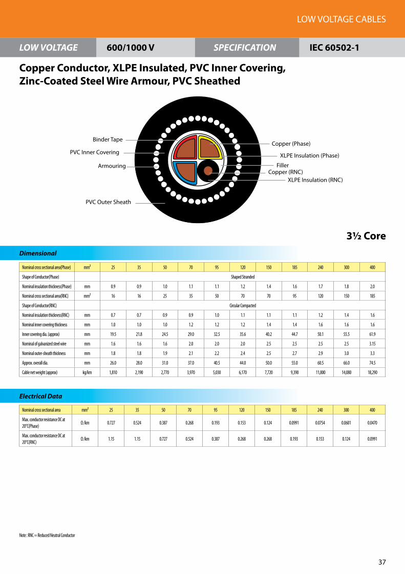
Nominal cross sectional area(Phase) mm² 25 35 50 70 95 120 150 185 240 300 400
Shape of Conductor(Phase) Shaped Stranded
Nominal insulation thickness(Phase) mm 0.9 0.9 1.0 1.1 1.1 1.2 1.4 1.6 1.7 1.8 2.0
Nominal cross sectional area(RNC) mm² 16 16 25 35 50 70 70 95 120 150 185
Shape of Conductor(RNC) Circular Compacted
Nominal insulation thickness(RNC) mm 0.7 0.7 0.9 0.9 1.0 1.1 1.1 1.1 1.2 1.4 1.6
Nominal inner covering thickness mm 1.0 1.0 1.0 1.2 1.2 1.2 1.4 1.4 1.6 1.6 1.6
Inner covering dia. (approx) mm 19.5 21.8 24.5 29.0 32.5 35.6 40.2 44.7 50.1 55.5 61.9
Nominal of galvanized steel wire mm 1.6 1.6 1.6 2.0 2.0 2.0 2.5 2.5 2.5 2.5 3.15
Nominal outer-sheath thickness mm 1.8 1.8 1.9 2.1 2.2 2.4 2.5 2.7 2.9 3.0 3.3
Approx. overall dia. mm 26.0 28.0 31.0 37.0 40.5 44.0 50.0 55.0 60.5 66.0 74.5
Cable net weight (approx) kg/km 1,810 2,190 2,770 3,970 5,030 6,170 7,720 9,390 11,800 14,080 18,290
Nominal cross sectional area mm² 25 35 50 70 95 120 150 185 240 300 400
Max. conductor resistance DC at 20°C(Phase)
Ω /km 0.727 0.524 0.387 0.268 0.193 0.153 0.124 0.0991 0.0754 0.0601 0.0470
Max. conductor resistance DC at 20°C(RNC)
Ω /km 1.15 1.15 0.727 0.524 0.387 0.268 0.268 0.193 0.153 0.124 0.0991
LOW VOLTAGE CABLES
37
LOW VOLTAGE SPECIFICATION
Dimensional
Electrical Data
Copper Conductor, XLPE Insulated, PVC Inner Covering,Zinc-Coated Steel Wire Armour, PVC Sheathed
3½ Core
600/1000 V IEC 60502-1
PVC Inner Covering
Armouring
PVC Outer Sheath
Copper (Phase)
XLPE Insulation (Phase)
Filler
Binder Tape
Copper (RNC)XLPE Insulation (RNC)
Note : RNC = Reduced Neutral Conductor

No. of cores 2 3 4 5 6 7 8 9 10 11 12 13 14 15 16 17 18
Shape of Conductor Circular Stranded
Conductor dia. (approx.) 1.59
Nominal insulation thickness
mm 0.8
Nominal sheath thickness mm 1.8
Approx. overall dia. mm 11.0 11.5 12.5 13.5 14.5 15.5 16.5 18.0 18.5 19.5 20.0 21.0
Cable net weight (approx.)
kg/km 140 170 200 240 270 280 330 370 400 420 450 480 510 550 570 610 630
No. of cores 19 20 21 22 23 24 25 26 27 28 29 30 37 40 48 50
Shape of Conductor Circular Stranded
Conductor dia. (approx.) 1.59
Nominal insulation thickness mm 0.8
Nominal sheath thickness mm 1.8 1.9
Approx. overall dia. mm 21.0 22.0 22.5 23.0 23.5 24.5 25.0 25.5 26.0 28.0 29.0 32.0
Cable net weight (approx.) kg/km 650 690 710 750 790 810 840 860 890 910 950 970 1,160 1,250 1,500 1,550
FEC Cables (M) Sdn. Bhd.
38
LOW VOLTAGE SPECIFICATION
Dimensional
Copper Conductor, PVC Insulated, PVC Sheathed Control
1.5 mm²
600/1000 V IEC 60502-1
PVC Sheath
Copper
PVC Insulation
Filler (If Necessary)
Binder Tape
Max. conductor resistance DC at 20°C = 12.10 Ω /kmCore Identification : Black numbers on white cores(for 2 cores up to 48 cores)For 50 cores, White insulation with number 1 - 28 and Red insulation with number 1 - 22

No. of cores 2 3 4 5 6 7 8 9 10 11 12 13 14 15 16 17 18
Shape of Conductor Circular Stranded
Conductor dia. (approx.) 2.01
Nominal insulation thickness
mm 0.8
Nominal sheath thickness mm 1.8
Approx. overall dia. mm 12.0 12.5 13.5 14.5 15.5 17.0 18.0 19.5 20.0 20.5 21.0 21.5 22.0 23.0 23.5
Cable net weight (approx.) kg/km 170 210 250 300 350 370 430 490 520 560 600 640 680 730 760 810 850
No. of cores 19 20 21 22 23 24 25 26 27 28 29 30 37 40 48 50
Shape of Conductor Circular Stranded
Conductor dia. (approx.)
2.01
Nominal insulation thickness
mm 0.8
Nominal sheath thickness
mm 1.8 1.9 1.9 2.0
Approx. overall dia. mm 23.5 24.0 24.5 25.0 25.5 27.0 27.5 28.0 28.5 31.5 32.5 36.0
Cable net weight (approx.)
kg/km 870 920 960 1,010 1,060 1,090 1,120 1,160 1,200 1,240 1,280 1,320 1,600 1,730 2,060 2,130
LOW VOLTAGE CABLES
39
LOW VOLTAGE SPECIFICATION
Dimensional
Copper Conductor, PVC Insulated, PVC Sheathed Control
2.5 mm²
600/1000 V IEC 60502-1
PVC Sheath
Copper
PVC Insulation
Filler (If Necessary)
Binder Tape
Max. conductor resistance DC at 20°C = 7.41 Ω /kmCore Identification : Black numbers on white cores(for 2 cores up to 48 cores)For 50 cores, White insulation with number 1 - 28 and Red insulation with number 1 - 22

No. of cores 2 3 4 5 6 7 8 9 10 11 12 13 14 15 16 17 18
Shape of Conductor Circular Stranded
Conductor dia. (approx.)
2.55
Nominal insulation thickness
mm 1.0
Nominal sheath thickness
mm 1.8
Approx. overall dia. mm 14.0 14.5 16.0 17.0 18.5 20.0 21.5 23.5 24.0 24.5 25.5 26.0 26.5 27.5 28.0
Cable net weight (approx.)
kg/km 230 290 360 440 510 540 630 720 770 830 890 950 1,010 1,090 1,140 1,220 1,270
No. of cores 19 20 21 22 23 24 25 26 27 28 29 30 37 40 48 50
Shape of Conductor Circular Stranded
Conductor dia. (approx.)
2.55
Nominal insulation thickness
mm 1.0
Nominal sheath thickness
mm 1.8 1.9 2.0 2.1 2.3
Approx. overall dia. mm 28.0 29.0 29.5 30.5 31.5 33.0 34.0 34.5 35.5 38.0 39.5 44.0
Cable net weight (approx.)
kg/km 1,300 1,390 1,450 1,540 1,620 1,670 1,720 1,780 1,860 1,910 1,980 2,040 2,460 2,670 3,200 3,310
FEC Cables (M) Sdn. Bhd.
�0
LOW VOLTAGE SPECIFICATION
Dimensional
Copper Conductor, PVC Insulated, PVC Sheathed Control
4 mm²
600/1000 V IEC 60502-1
PVC Sheath
Copper
PVC Insulation
Filler (If Necessary)
Binder Tape
Max. conductor resistance DC at 20°C = 4.61 Ω /kmCore Identification : Black numbers on white cores(for 2 cores up to 48 cores)For 50 cores, White insulation with number 1 - 28 and Red insulation with number 1 - 22

No. of cores 2 3 4 5 6 7 8 9 10 11 12 13 14 15 16 17 18
Shape of Conductor Circular Stranded
Conductor dia. (approx.)
1.59
Nominal insulation thickness
mm 0.8
Nominal sheath thickness
mm 1.8
Approx. overall dia. mm 11.5 12.0 13.0 14.0 15.0 16.0 17.0 18.5 19.0 19.5 20.0 20.5 21.0 21.5
Cable net weight (approx.)
kg/km 170 200 230 270 310 330 370 420 450 480 510 540 570 610 630 680 700
No. of cores 19 20 21 22 23 24 25 26 27 28 29 30 37 40 48 50
Shape of Conductor Circular Stranded
Conductor dia. (approx.) 1.59
Nominal insulation thickness
mm 0.8
Nominal sheath thickness
mm 1.8 1.9 2.0
Approx. overall dia. mm 21.5 22.5 23.5 24.0 25.0 25.5 26.0 26.5 29.0 30.0 33.0
Cable net weight (approx.)
kg/km 710 760 780 820 860 890 910 940 970 990 1,030 1,060 1,270 1,360 1,620 1,670
LOW VOLTAGE CABLES
�1
LOW VOLTAGE SPECIFICATION
Dimensional
Copper Conductor, PVC Insulated, PVC Sheathed (Screened-CU Tape) Control
1.5 mm²
600/1000 V IEC 60502-1
PVC Sheath
Copper
PVC Insulation
Filler (If Necessary)
Binder Tape
Screening
Binder Tape
Max. conductor resistance DC at 20°C = 12.10 Ω /kmCore Identification : Black numbers on white cores(for 2 cores up to 48 cores)For 50 cores, White insulation with number 1 - 28 and Red insulation with number 1 - 22

No. of cores 2 3 4 5 6 7 8 9 10 11 12 13 14 15 16 17 18
Shape of Conductor Circular Stranded
Conductor dia. (approx.)
2.01
Nominal insulation thickness
mm 0.8
Nominal sheath thickness
mm 1.8
Approx. overall dia. mm 12.5 13.0 14.0 15.0 16.0 17.5 18.5 20.0 20.5 21.0 21.5 22.0 22.5 23.5 24.0
Cable net weight (approx.)
kg/km 200 240 290 340 400 410 480 540 580 620 660 700 740 790 830 890 920
No. of cores 19 20 21 22 23 24 25 26 27 28 29 30 37 40 48 50
Shape of Conductor Circular Stranded
Conductor dia. (approx.) 2.01
Nominal insulation thickness mm 0.8
Nominal sheath thickness mm 1.8 1.9 2.0 2.1 2.2
Approx. overall dia. mm 24.0 24.5 25.0 25.5 26.0 27.5 28.5 29.0 29.5 32.0 33.0 36.5
Cable net weight (approx.) kg/km 940 1,000 1,030 1,090 1,140 1,170 1,210 1,250 1,310 1,340 1,390 1,430 1,710 1,840 2,190 2,280
FEC Cables (M) Sdn. Bhd.
�2
LOW VOLTAGE SPECIFICATION
Dimensional
Copper Conductor, PVC Insulated, PVC Sheathed (Screened-CU Tape) Control
2.5 mm²
600/1000 V IEC 60502-1
PVC Sheath
Copper
PVC Insulation
Filler (If Necessary)
Binder Tape
Screening
Binder Tape
Max. conductor resistance DC at 20°C = 7.41 Ω /kmCore Identification : Black numbers on white cores(for 2 cores up to 48 cores)For 50 cores, White insulation with number 1 - 28 and Red insulation with number 1 - 22

No. of cores 2 3 4 5 6 7 8 9 10 11 12 13 14 15 16 17 18
Shape of Conductor Circular Stranded
Conductor dia. (approx.)
2.55
Nominal insulation thickness
mm 1.0
Nominal sheath thickness
mm 1.8 1.9
Approx. overall dia. mm 14.0 15.0 16.0 17.5 19.0 20.5 22.0 23.5 24.5 25.0 25.5 26.5 27.0 28.0 29.0
Cable net weight (approx.)
kg/km 270 330 410 490 570 600 690 790 840 900 960 1,030 1,090 1,170 1,230 1,330 1,380
No. of cores 19 20 21 22 23 24 25 26 27 28 29 30 37 40 48 50
Shape of Conductor Circular Stranded
Conductor dia. (approx.) 2.55
Nominal insulation thickness
mm 1.0
Nominal sheath thickness
mm 1.9 2.0 2.1 2.2 2.3 2.4
Approx. overall dia. mm 29.0 29.5 30.0 31.5 32.0 33.5 34.5 35.0 36.0 39.0 40.5 45.0
Cable net weight (approx.)
kg/km 1,410 1,500 1,560 1,660 1,730 1,790 1,840 1,900 1,980 2,040 2,110 2,170 2,600 2,830 3,370 3,480
LOW VOLTAGE CABLES
�3
LOW VOLTAGE SPECIFICATION
Dimensional
Copper Conductor, PVC Insulated, PVC Sheathed (Screened-CU Tape) Control
4 mm²
600/1000 V IEC 60502-1
PVC Sheath
Copper
PVC Insulation
Filler (If Necessary)
Binder Tape
Screening
Binder Tape
Max. conductor resistance DC at 20°C = 4.61 Ω /kmCore Identification : Black numbers on white cores(for 2 cores up to 48 cores)For 50 cores, White insulation with number 1 - 28 and Red insulation with number 1 - 22

No. of cores 2 3 4 5 6 7 8 9 10 11 12 13 14 15 16 17 18
Shape of Conductor Circular Stranded
Conductor dia. (approx.) 1.59
Nominal insulation thickness
mm 0.8
Nominal inner covering thickness
mm 1.0
Inner covering dia. (approx.)
mm 8.7 9.3 10.1 11.1 12.1 13.2 14.2 15.5 16.0 16.3 16.9 17.4 17.9 18.4 18.9
Nominal of galvanized steel wire
mm 0.9 1.6
Nominal outer-sheath thickness
mm 1.8
Approx. overall dia. mm 14.0 14.5 15.5 16.5 17.5 18.5 19.5 21.0 21.5 22.5 23.0 25.0 25.5
Cable net weight (approx.)
kg/km 340 370 430 480 540 550 610 680 730 760 800 830 870 920 950 1,270 1,310
No. of cores 19 20 21 22 23 24 25 26 27 28 29 30 37 40 48 50
Shape of Conductor Circular Stranded
Conductor dia. (approx.) 1.59
Nominal insulation thickness mm 0.8
Nominal inner covering thickness mm 1.0
Inner covering dia. (approx.) mm 18.9 19.5 19.9 20.6 21.0 22.3 22.8 23.1 23.7 25.7 26.7 29.6
Nominal of galvanized steel wire mm 1.6 2.0
Nominal outer-sheath thickness mm 1.8 1.9 2.0
Approx. overall dia. mm 25.5 26.5 27.5 29.0 29.5 30.0 30.5 32.5 33.5 37.5
Cable net weight (approx.) kg/km 1,320 1,380 1,430 1,480 1,530 1,590 1,620 1,640 1,690 1,720 1,760 1,810 2,080 2,210 2,790 2,840
FEC Cables (M) Sdn. Bhd.
��
LOW VOLTAGE SPECIFICATION
Dimensional
Copper Conductor, PVC Insulated, PVC Inner Covering, Zinc-Coated Steel Wire Armour, PVC Sheathed Control
1.5 mm²
600/1000 V IEC 60502-1
PVC Outer Sheath
PVC Inner Covering
Armouring
Copper
PVC Insulation
Filler (If Necessary)
Binder Tape
Max. conductor resistance DC at 20°C = 12.10 Ω /kmCore Identification : Black numbers on white cores(for 2 cores up to 48 cores)For 50 cores, White insulation with number 1 - 28 and Red insulation with number 1 - 22
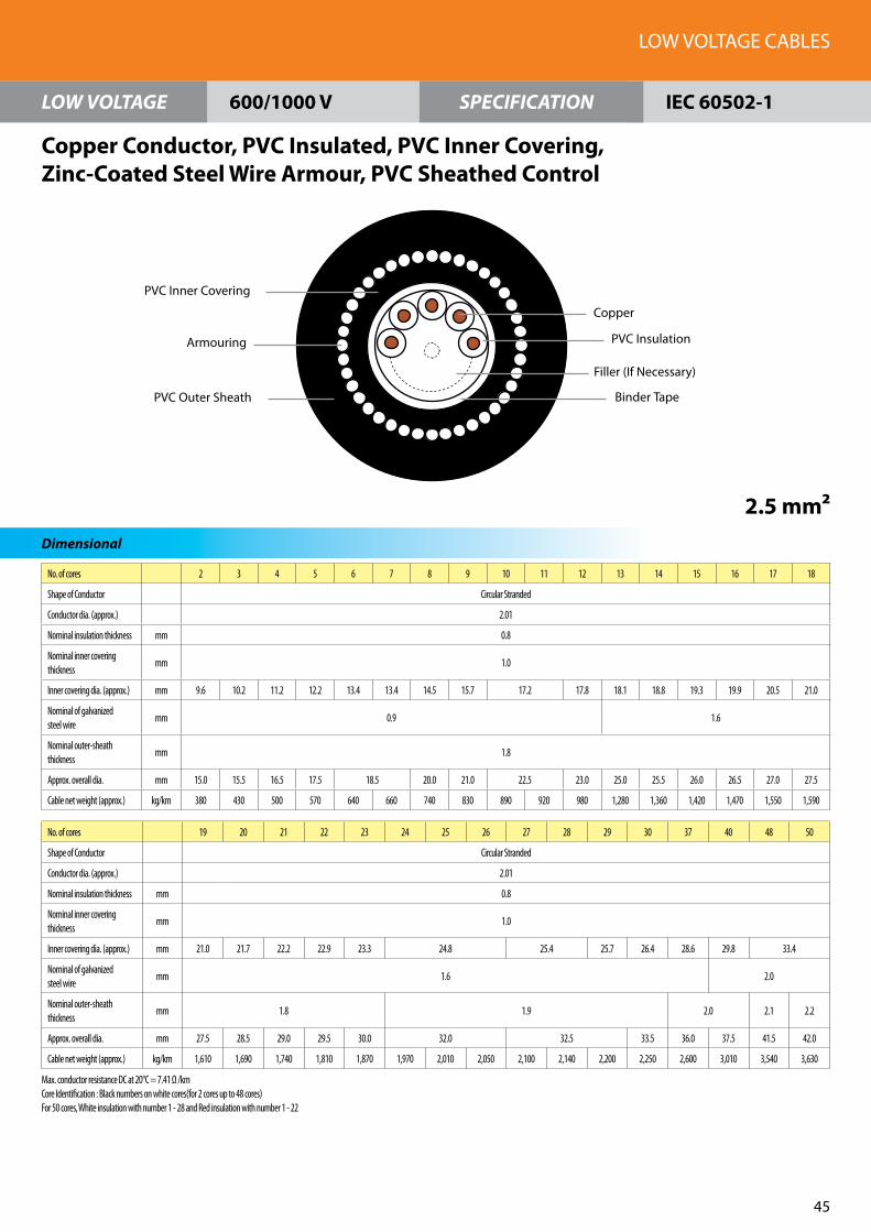
No. of cores 2 3 4 5 6 7 8 9 10 11 12 13 14 15 16 17 18
Shape of Conductor Circular Stranded
Conductor dia. (approx.) 2.01
Nominal insulation thickness mm 0.8
Nominal inner covering thickness
mm 1.0
Inner covering dia. (approx.) mm 9.6 10.2 11.2 12.2 13.4 13.4 14.5 15.7 17.2 17.8 18.1 18.8 19.3 19.9 20.5 21.0
Nominal of galvanized steel wire
mm 0.9 1.6
Nominal outer-sheath thickness
mm 1.8
Approx. overall dia. mm 15.0 15.5 16.5 17.5 18.5 20.0 21.0 22.5 23.0 25.0 25.5 26.0 26.5 27.0 27.5
Cable net weight (approx.) kg/km 380 430 500 570 640 660 740 830 890 920 980 1,280 1,360 1,420 1,470 1,550 1,590
No. of cores 19 20 21 22 23 24 25 26 27 28 29 30 37 40 48 50
Shape of Conductor Circular Stranded
Conductor dia. (approx.) 2.01
Nominal insulation thickness mm 0.8
Nominal inner covering thickness
mm 1.0
Inner covering dia. (approx.) mm 21.0 21.7 22.2 22.9 23.3 24.8 25.4 25.7 26.4 28.6 29.8 33.4
Nominal of galvanized steel wire
mm 1.6 2.0
Nominal outer-sheath thickness
mm 1.8 1.9 2.0 2.1 2.2
Approx. overall dia. mm 27.5 28.5 29.0 29.5 30.0 32.0 32.5 33.5 36.0 37.5 41.5 42.0
Cable net weight (approx.) kg/km 1,610 1,690 1,740 1,810 1,870 1,970 2,010 2,050 2,100 2,140 2,200 2,250 2,600 3,010 3,540 3,630
LOW VOLTAGE CABLES
�5
LOW VOLTAGE SPECIFICATION
Dimensional
Copper Conductor, PVC Insulated, PVC Inner Covering, Zinc-Coated Steel Wire Armour, PVC Sheathed Control
2.5 mm²
600/1000 V IEC 60502-1
PVC Outer Sheath
PVC Inner Covering
Armouring
Copper
PVC Insulation
Filler (If Necessary)
Binder Tape
Max. conductor resistance DC at 20°C = 7.41 Ω /kmCore Identification : Black numbers on white cores(for 2 cores up to 48 cores)For 50 cores, White insulation with number 1 - 28 and Red insulation with number 1 - 22

No. of cores 2 3 4 5 6 7 8 9 10 11 12 13 14 15 16 17 18
Shape of Conductor Circular Stranded
Conductor dia. (approx.) 2.55
Nominal insulation thickness mm 1.0
Nominal inner covering thickness mm 1.0
Inner covering dia. (approx.) mm 11.5 12.2 13.4 14.8 16.2 17.6 19.1 21.0 21.7 22.1 22.9 23.6 24.3 25.1 25.7
Nominal of galvanized steel wire mm 0.9 1.6
Nominal outer-sheath thickness mm 1.8 1.9
Approx. overall dia. mm 17.0 17.5 19.0 20.0 21.5 24.5 26.0 27.5 28.5 29.0 29.5 30.5 31.0 32.0 32.5
Cable net weight (approx.) kg/km 490 560 650 760 860 890 1,270 1,400 1,520 1,570 1,650 1,740 1,810 1,920 1,990 2,110 2,190
No. of cores 19 20 21 22 23 24 25 26 27 28 29 30 37 40 48 50
Shape of Conductor Circular Stranded
Conductor dia. (approx.) 2.55
Nominal insulation thickness mm 1.0
Nominal inner covering thickness
mm 1.0 1.2 1.4
Inner covering dia. (approx.) mm 25.7 26.5 27.1 28.1 28.6 30.9 31.6 32.0 32.8 35.6 37.0 41.5
Nominal of galvanized steel wire mm 1.6 2.0 2.5
Nominal outer-sheath thickness mm 1.9 2.0 2.1 2.2 2.3 2.4
Approx. overall dia. mm 32.5 33.5 34.0 36.0 36.5 39.0 39.5 40.0 41.0 44.0 45.5 51.0
Cable net weight (approx.) kg/km 2,220 2,330 2,400 2,780 2,850 3,050 3,110 3,170 3,260 3,310 3,380 3,490 4,030 4,310 5,460 5,580
FEC Cables (M) Sdn. Bhd.
�6
LOW VOLTAGE SPECIFICATION
Dimensional
Copper Conductor, PVC Insulated, PVC Inner Covering, Zinc-Coated Steel Wire Armour, PVC Sheathed Control
4 mm²
600/1000 V IEC 60502-1
PVC Outer Sheath
PVC Inner Covering
Armouring
Copper
PVC Insulation
Filler (If Necessary)
Binder Tape
Max. conductor resistance DC at 20°C = 4.61 Ω /kmCore Identification : Black numbers on white cores(for 2 cores up to 48 cores)For 50 cores, White insulation with number 1 - 28 and Red insulation with number 1 - 22

No. of cores 2 3 4 5 6 7 8 9 10 11 12 13 14 15 16 17 18
Shape of Conductor Circular Stranded
Conductor dia. (approx.) 1.59
Nominal insulation thickness mm 0.8
Nominal inner covering thickness mm 1.0
Inner covering dia. (approx.) mm 9.2 9.7 10.6 11.5 12.6 12.6 13.6 14.6 16.0 16.0 16.5 16.8 17.4 17.8 18.3 18.9 19.3
Nominal of galvanized steel wire mm 0.9 1.6
Nominal outer-sheath thickness mm 1.8
Approx. overall dia. mm 14.5 15.0 16.0 17.0 18.0 19.0 20.0 21.5 23.0 23.5 24.0 24.5 25.0 25.5 26.0
Cable net weight (approx.) kg/km 370 420 470 530 590 600 670 740 800 820 1,100 1,150 1,190 1,250 1,290 1,350 1,390
No. of cores 19 20 21 22 23 24 25 26 27 28 29 30 37 40 48 50
Shape of Conductor Circular Stranded
Conductor dia. (approx.) 1.59
Nominal insulation thickness mm 0.8
Nominal inner covering thickness mm 1.0 1.2
Inner covering dia. (approx.) mm 19.3 20.0 20.4 21.0 21.4 22.7 22.7 22.7 23.3 23.3 23.6 24.1 26.1 27.6 30.4
Nominal of galvanized steel wire mm 1.6 2.0
Nominal outer-sheath thickness mm 1.8 1.9 2.0 2.1 2.2
Approx. overall dia. mm 26.0 26.5 27.0 28.0 29.5 30.0 30.5 31.0 34.0 35.5 39.0
Cable net weight (approx.) kg/km 1,410 1,470 1,510 1,570 1,620 1,700 1,730 1,750 1,800 1,820 1,870 1,920 2,420 2,610 2,980 3,030
LOW VOLTAGE CABLES
�7
LOW VOLTAGE SPECIFICATION
Dimensional
Copper Conductor, PVC Insulated, PVC Inner Covering, Zinc-Coated Steel Wire Armour, PVC Sheathed (Screened-CU Tape) Control
1.5 mm²
600/1000 V IEC 60502-1
PVC Outer Sheath
Copper
PVC Insulation
Filler (If Necessary)
Binder Tape
PVC Inner Covering
Binder Tape
Amouring
Screening
Max. conductor resistance DC at 20°C = 12.10 Ω /kmCore Identification : Black numbers on white cores(for 2 cores up to 48 cores)For 50 cores, White insulation with number 1 - 28 and Red insulation with number 1 - 22

No. of cores 2 3 4 5 6 7 8 9 10 11 12 13 14 15 16 17 18
Shape of Conductor Circular Stranded
Conductor dia. (approx.) 2.01
Nominal insulation thickness mm 0.8
Nominal inner covering thickness
mm 1.0
Inner covering dia. (approx.) mm 10.0 10.6 11.6 12.7 13.8 15.0 16.2 17.6 18.2 18.5 19.2 19.7 20.3 20.9 21.4
Nominal of galvanized steel wire
mm 0.9 1.6
Nominal outer-sheath thickness mm 1.8
Approx. overall dia. mm 15.5 16.0 17.0 18.0 19.0 20.5 23.0 24.5 25.0 25.5 26.0 26.5 27.0 27.5 28.0
Cable net weight (approx.) kg/km 430 480 550 620 700 720 800 1,130 1,220 1,260 1,320 1,360 1,440 1,510 1,560 1,630 1,680
No. of cores 19 20 21 22 23 24 25 26 27 28 29 30 37 40 48 50
Shape of Conductor Circular Stranded
Conductor dia. (approx.) 2.01
Nominal insulation thickness mm 0.8
Nominal inner covering thickness
mm 1.0 1.2
Inner covering dia. (approx.) mm 21.4 22.1 22.6 23.3 23.8 25.3 25.8 26.1 26.8 29.5 30.6 33.9
Nominal of galvanized steel wire mm 1.6 2.0
Nominal outer-sheath thickness mm 1.8 1.9 1.9 2.0 2.1 2.2 2.3
Approx. overall dia. mm 28.0 29.0 29.5 30.5 32.5 33.0 34.0 35.0 37.5 39.0 42.5
Cable net weight (approx.) kg/km 1,700 1,790 1,850 1,920 1,990 2,090 2,130 2,160 2,220 2,470 2,540 2,600 3,030 3,210 3,690 3,760
FEC Cables (M) Sdn. Bhd.
�8
LOW VOLTAGE SPECIFICATION
Dimensional
Copper Conductor, PVC Insulated, PVC Inner Covering, Zinc-Coated Steel Wire Armour, PVC Sheathed (Screened-CU Tape) Control
2.5 mm²
600/1000 V IEC 60502-1
PVC Outer Sheath
Copper
PVC Insulation
Filler (If Necessary)
Binder Tape
PVC Inner Covering
Binder Tape
Amouring
Screening
Max. conductor resistance DC at 20°C = 7.41 Ω /kmCore Identification : Black numbers on white cores(for 2 cores up to 48 cores)For 50 cores, White insulation with number 1 - 28 and Red insulation with number 1 - 22

No. of cores 2 3 4 5 6 7 8 9 10 11 12 13 14 15 16 17 18
Shape of Conductor Circular Stranded
Conductor dia. (approx.) 2.55
Nominal insulation thickness mm 1.0
Nominal inner covering thickness mm 1.0
Inner covering dia. (approx.) mm 11.9 12.6 13.9 15.2 16.6 18.1 19.6 21.4 22.1 22.5 23.4 24.0 24.7 25.5 26.1
Nominal of galvanized steel wire mm 0.9 1.6
Nominal outer-sheath thickness mm 1.8 1.9 2.0
Approx. overall dia. mm 17.0 18.0 19.0 20.5 23.5 25.0 26.5 28.0 29.0 29.5 30.5 31.0 31.5 32.5 33.5
Cable net weight (approx.) kg/km 530 610 710 810 1,170 1,200 1,330 1,480 1,610 1,660 1,740 1,840 1,920 2,020 2,110 2,230 2,310
No. of cores 19 20 21 22 23 24 25 26 27 28 29 30 37 40 48 50
Shape of Conductor Circular Stranded
Conductor dia. (approx.) 2.55
Nominal insulation thickness
mm 1.0
Nominal inner covering thickness
mm 1.0 1.2 1.4
Inner covering dia. (approx.)
mm 26.1 27.4 28.0 28.9 29.5 31.3 32.0 32.0 32.4 33.3 36.0 37.9 41.9
Nominal of galvanized steel wire
mm 1.6 2.0 2.5 2.5
Nominal outer-sheath thickness
mm 2.0 2.1 2.2 2.3 2.4 2.6
Approx. overall dia. mm 33.5 35.5 36.0 37.0 37.5 39.5 40.5 41.0 41.5 44.5 47.5 52.0
Cable net weight (approx.)
kg/km 2,340 2,750 2,810 2,950 3,050 3,180 3,240 3,290 3,410 3,470 3,540 3,630 4,200 4,920 5,680 5,800
LOW VOLTAGE CABLES
�9
LOW VOLTAGE SPECIFICATION
Dimensional
Copper Conductor, PVC Insulated, PVC Inner Covering, Zinc-Coated Steel Wire Armour, PVC Sheathed (Screened-CU Tape) Control
4 mm²
600/1000 V IEC 60502-1
PVC Outer Sheath
Copper
PVC Insulation
Filler (If Necessary)
Binder Tape
PVC Inner Covering
Binder Tape
Amouring
Screening
Max. conductor resistance DC at 20°C = 4.61 Ω /kmCore Identification : Black numbers on white cores(for 2 cores up to 48 cores)For 50 cores, White insulation with number 1 - 28 and Red insulation with number 1 - 22

No. of cores 2 3 4 5 6 7 8 9 10 11 12 13 14 15 16 17 18
Shape of Conductor Circular Stranded
Conductor dia. (approx.) 1.59
Nominal insulation thickness mm 0.7
Nominal sheath thickness mm 1.8
Approx. overall dia. mm 10.5 11.0 12.0 13.0 14.0 15.0 16.0 17.0 17.5 18.0 18.5 19.0 19.5 20.0 20.5
Cable net weight (approx.) kg/km 130 150 180 210 240 250 280 320 340 360 390 410 430 460 490 520 540
No. of cores 19 20 21 22 23 24 25 26 27 28 29 30 37 40 48 50
Shape of Conductor Circular Stranded
Conductor dia. (approx.) 1.59
Nominal insulation thickness mm 0.7
Nominal sheath thickness mm 1.8
Approx. overall dia. mm 20.5 21.0 21.5 22.0 22.5 23.5 24.0 24.5 25.0 26.5 27.5 30.5
Cable net weight (approx.) kg/km 540 580 600 630 660 680 700 720 750 770 790 820 960 1,040 1,230 1,270
FEC Cables (M) Sdn. Bhd.
50
LOW VOLTAGE SPECIFICATION
Dimensional
Copper Conductor, XLPE Insulated, PVC Sheathed Control
1.5 mm²
600/1000 V IEC 60502-1
PVC Sheath
Copper
XLPE Insulation
Filler (If Necessary)
Binder Tape
Max. conductor resistance DC at 20°C = 12.10 Ω /kmCore Identification : Black numbers on white cores(for 2 cores up to 48 cores)For 50 cores, White insulation with number 1 - 28 and Red insulation with number 1 - 22

No. of cores 2 3 4 5 6 7 8 9 10 11 12 13 14 15 16 17 18
Shape of Conductor Circular Stranded
Conductor dia. (approx.) 2.01
Nominal insulation thickness
mm 0.7
Nominal sheath thickness mm 1.8
Approx. overall dia. mm 11.5 12.0 13.0 14.0 15.0 16.5 17.5 19.0 19.5 20.0 20.5 21.0 21.5 22.0 22.5
Cable net weight (approx.) kg/km 160 190 230 270 310 330 370 420 460 490 520 560 590 630 660 700 730
No. of cores 19 20 21 22 23 24 25 26 27 28 29 30 37 40 48 50
Shape of Conductor Circular Stranded
Conductor dia. (approx.) 2.01
Nominal insulation thickness
mm 0.7
Nominal sheath thickness mm 1.8 1.9
Approx. overall dia. mm 22.5 23.0 23.5 24.0 24.5 26.0 26.5 27.0 27.5 30.0 31.0 34.0
Cable net weight (approx.) kg/km 750 790 820 860 900 940 970 1,000 1,030 1,060 1,090 1,130 1,350 1,450 1,740 1,800
LOW VOLTAGE CABLES
51
LOW VOLTAGE SPECIFICATION
Dimensional
Copper Conductor, XLPE Insulated, PVC Sheathed Control
2.5 mm²
600/1000 V IEC 60502-1
PVC Sheath
Copper
XLPE Insulation
Filler (If Necessary)
Binder Tape
Max. conductor resistance DC at 20°C = 7.41 Ω /kmCore Identification : Black numbers on white cores(for 2 cores up to 48 cores)For 50 cores, White insulation with number 1 - 28 and Red insulation with number 1 - 22

No. of cores 2 3 4 5 6 7 8 9 10 11 12 13 14 15 16 17 18
Shape of Conductor Circular Stranded
Conductor dia. (approx.) 2.55
Nominal insulation thickness
mm 0.7
Nominal sheath thickness
mm 1.8
Approx. overall dia. mm 12.5 13.0 14.0 15.5 16.5 18.0 19.0 21.0 21.5 22.0 22.5 23.0 23.5 24.5 25.0
Cable net weight (approx.)
kg/km 200 250 300 360 420 450 510 580 630 680 720 780 830 880 930 990 1,040
No. of cores 19 20 21 22 23 24 25 26 27 28 29 30 37 40 48 50
Shape of Conductor Circular Stranded
Conductor dia. (approx.)
2.55
Nominal insulation thickness
mm 0.7
Nominal sheath thickness
mm 1.8 1.8 1.8 1.8 1.8 1.9 2.1
Approx. overall dia. mm 25.0 25.5 26.0 27.0 27.5 29.0 30.0 31.0 33.5 35.0 38.5
Cable net weight (approx.)
kg/km 1,060 1,120 1,170 1,230 1,280 1,340 1,380 1,430 1,470 1,520 1,570 1,620 1,960 2,120 2,550 2,640
FEC Cables (M) Sdn. Bhd.
52
LOW VOLTAGE SPECIFICATION
Dimensional
Copper Conductor, XLPE Insulated, PVC Sheathed Control
4 mm²
600/1000 V IEC 60502-1
PVC Sheath
Copper
XLPE Insulation
Filler (If Necessary)
Binder Tape
Max. conductor resistance DC at 20°C = 4.61 Ω /kmCore Identification : Black numbers on white cores(for 2 cores up to 48 cores)For 50 cores, White insulation with number 1 - 28 and Red insulation with number 1 - 22
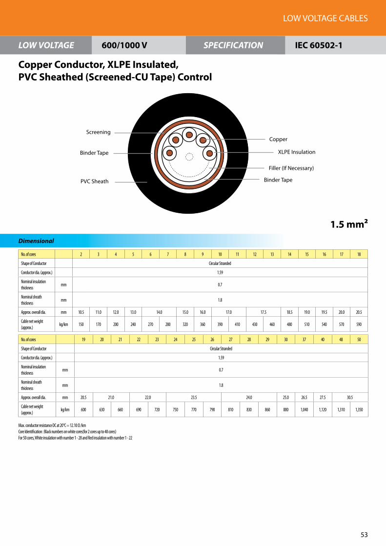
No. of cores 2 3 4 5 6 7 8 9 10 11 12 13 14 15 16 17 18
Shape of Conductor Circular Stranded
Conductor dia. (approx.) 1.59
Nominal insulation thickness
mm 0.7
Nominal sheath thickness
mm 1.8
Approx. overall dia. mm 10.5 11.0 12.0 13.0 14.0 15.0 16.0 17.0 17.5 18.5 19.0 19.5 20.0 20.5
Cable net weight (approx.)
kg/km 150 170 200 240 270 280 320 360 390 410 430 460 480 510 540 570 590
No. of cores 19 20 21 22 23 24 25 26 27 28 29 30 37 40 48 50
Shape of Conductor Circular Stranded
Conductor dia. (approx.) 1.59
Nominal insulation thickness
mm 0.7
Nominal sheath thickness
mm 1.8
Approx. overall dia. mm 20.5 21.0 22.0 23.5 24.0 25.0 26.5 27.5 30.5
Cable net weight (approx.)
kg/km 600 630 660 690 720 750 770 790 810 830 860 880 1,040 1,120 1,310 1,350
LOW VOLTAGE CABLES
53
LOW VOLTAGE SPECIFICATION
Dimensional
Copper Conductor, XLPE Insulated, PVC Sheathed (Screened-CU Tape) Control
1.5 mm²
600/1000 V IEC 60502-1
PVC Sheath
Copper
XLPE Insulation
Filler (If Necessary)
Binder Tape
Screening
Binder Tape
Max. conductor resistance DC at 20°C = 12.10 Ω /kmCore Identification : Black numbers on white cores(for 2 cores up to 48 cores)For 50 cores, White insulation with number 1 - 28 and Red insulation with number 1 - 22
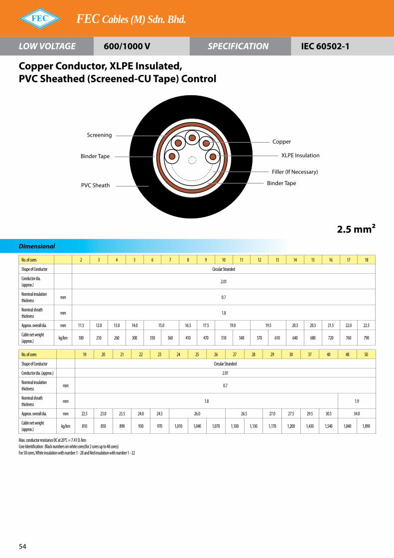
No. of cores 2 3 4 5 6 7 8 9 10 11 12 13 14 15 16 17 18
Shape of Conductor Circular Stranded
Conductor dia. (approx.)
2.01
Nominal insulation thickness
mm 0.7
Nominal sheath thickness
mm 1.8
Approx. overall dia. mm 11.5 12.0 13.0 14.0 15.0 16.5 17.5 19.0 19.5 20.5 20.5 21.5 22.0 22.5
Cable net weight (approx.)
kg/km 180 210 260 300 350 360 410 470 510 540 570 610 640 680 720 760 790
No. of cores 19 20 21 22 23 24 25 26 27 28 29 30 37 40 48 50
Shape of Conductor Circular Stranded
Conductor dia. (approx.) 2.01
Nominal insulation thickness
mm 0.7
Nominal sheath thickness
mm 1.8 1.9
Approx. overall dia. mm 22.5 23.0 23.5 24.0 24.5 26.0 26.5 27.0 27.5 29.5 30.5 34.0
Cable net weight (approx.)
kg/km 810 850 890 930 970 1,010 1,040 1,070 1,100 1,130 1,170 1,200 1,430 1,540 1,840 1,890
FEC Cables (M) Sdn. Bhd.
5�
LOW VOLTAGE SPECIFICATION
Dimensional
Copper Conductor, XLPE Insulated, PVC Sheathed (Screened-CU Tape) Control
2.5 mm²
600/1000 V IEC 60502-1
PVC Sheath
Binder Tape
Screening
Binder Tape
Copper
XLPE Insulation
Filler (If Necessary)
Max. conductor resistance DC at 20°C = 7.41 Ω /kmCore Identification : Black numbers on white cores(for 2 cores up to 48 cores)For 50 cores, White insulation with number 1 - 28 and Red insulation with number 1 - 22

No. of cores 2 3 4 5 6 7 8 9 10 11 12 13 14 15 16 17 18
Shape of Conductor Circular Stranded
Conductor dia. (approx.)
2.55
Nominal insulation thickness
mm 0.7
Nominal sheath thickness
mm 1.8
Approx. overall dia. mm 12.5 13.0 14.5 15.5 16.5 18.0 19.5 21.0 21.5 22.0 22.5 23.0 24.0 24.5 25.0
Cable net weight (approx.)
kg/km 230 280 340 400 470 490 560 630 690 740 790 840 890 950 1,000 1,060 1,110
No. of cores 19 20 21 22 23 24 25 26 27 28 29 30 37 40 48 50
Shape of Conductor Circular Stranded
Conductor dia. (approx.) 2.55
Nominal insulation thickness
mm 0.7
Nominal sheath thickness
mm 1.8 1.9 2.0 2.1
Approx. overall dia. mm 25.0 26.0 26.5 27.0 27.5 29.0 30.0 30.5 31.0 33.5 35.0 39.0
Cable net weight (approx.)
kg/km 1,130 1,200 1,250 1,310 1,370 1,420 1,470 1,510 1,560 1,620 1,680 1,730 2,060 2,240 2,670 2,760
LOW VOLTAGE CABLES
55
LOW VOLTAGE SPECIFICATION
Dimensional
Copper Conductor, XLPE Insulated, PVC Sheathed (Screened-CU Tape) Control
4 mm²
600/1000 V IEC 60502-1
PVC Sheath
Binder Tape
Screening
Binder Tape
Copper
Filler (If Necessary)
XLPE Insulation
Max. conductor resistance DC at 20°C = 4.61 Ω /kmCore Identification : Black numbers on white cores(for 2 cores up to 48 cores)For 50 cores, White insulation with number 1 - 28 and Red insulation with number 1 - 22

No. of cores 2 3 4 5 6 7 8 9 10 11 12 13 14 15 16 17 18
Shape of Conductor Circular Stranded
Conductor dia. (approx.) 1.59
Nominal insulation thickness mm 0.7
Nominal inner covering thickness mm 1.0
Inner covering dia. (approx.) mm 9.0 9.5 10.3 11.2 12.2 13.1 14.1 15.3 15.8 16.1 16.7 17.1 17.6 18.1 18.5
Nominal of galvanized steel wire mm 0.9 1.25
Nominal outer-sheath thickness mm 1.8
Approx. overall dia. mm 14.0 14.5 15.5 16.0 17.0 19.0 20.0 21.0 21.5 22.0 22.5 23.0 23.5 24.0 24.5
Cable net weight (approx.) kg/km 350 380 420 470 520 530 680 750 800 820 860 890 920 960 1,000 1,050 1,080
No. of cores 19 20 21 22 23 24 25 26 27 28 29 30 37 40 48 50
Shape of Conductor Circular Stranded
Conductor dia. (approx.) 1.59
Nominal insulation thickness mm 0.7
Nominal inner covering thickness
mm 1.0
Inner covering dia. (approx.) mm 18.5 19.1 19.5 20.1 20.5 21.7 22.2 22.5 23.0 24.9 25.9 28.6
Nominal of galvanized steel wire mm 1.25 1.6
Nominal outer-sheath thickness mm 1.8 1.9
Approx. overall dia. mm 24.5 25.5 26.0 26.5 27.0 28.0 28.5 29.0 29.5 31.5 32.5 35.5
Cable net weight (approx.) kg/km 1,090 1,270 1,310 1,360 1,400 1,460 1,490 1,500 1,550 1,570 1,590 1,630 1,840 1,960 2,240 2,280
FEC Cables (M) Sdn. Bhd.
56
LOW VOLTAGE SPECIFICATION
Dimensional
Copper Conductor, XLPE Insulated, PVC Inner Covering, Zinc-Coated Steel Wire Armour, PVC Sheated Control
1.5 mm²
600/1000 V IEC 60502-1
PVC Outer Sheath
PVC Inner Covering
Armouring
Copper
XLPE Insulation
Filler (If Necessary)
Binder Tape
Max. conductor resistance DC at 20°C = 12.10 Ω /kmCore Identification : Black numbers on white cores(for 2 cores up to 48 cores)For 50 cores, White insulation with number 1 - 28 and Red insulation with number 1 - 22

No. of cores 2 3 4 5 6 7 8 9 10 11 12 13 14 15 16 17 18
Shape of Conductor Circular Stranded
Conductor dia. (approx.) 2.01
Nominal insulation thickness mm 0.7
Nominal inner covering thickness mm 1.0
Inner covering dia. (approx.) mm 9.8 10.4 11.3 12.3 13.4 14.5 15.6 17.0 17.6 17.9 18.5 19.0 19.6 20.1 20.6
Nominal of galvanized steel wire mm 0.9 1.25 1.6
Nominal outer-sheath thickness mm 1.8
Approx. overall dia. mm 15.0 15.5 16.5 17.5 19.0 20.5 21.5 23.0 23.5 24.0 25.5 26.0 26.5 27.0
Cable net weight (approx.) kg/km 390 430 490 560 720 730 810 880 960 980 1,040 1,080 1,130 1,320 1,370 1,430 1,480
No. of cores 19 20 21 22 23 24 25 26 27 28 29 30 37 40 48 50
Shape of Conductor Circular Stranded
Conductor dia. (approx.) 2.01
Nominal insulation thickness mm 0.7
Nominal inner covering thickness mm 1.0 1.2
Inner covering dia. (approx.) mm 20.6 21.3 21.7 22.4 22.8 24.2 24.8 25.1 25.7 27.9 29.0 32.4
Nominal of galvanized steel wire mm 1.6 2.0
Nominal outer-sheath thickness mm 1.8 1.9 2.0 2.1
Approx. overall dia. mm 27.0 27.5 28.5 29.0 29.5 31.0 31.5 32.0 32.5 34.5 36.0 40.5
Cable net weight (approx.) kg/km 1,490 1,550 1,600 1,660 1,720 1,790 1,820 1,850 1,900 1,950 2,000 2,050 2,340 2,500 3,190 3,250
LOW VOLTAGE CABLES
57
LOW VOLTAGE SPECIFICATION
Dimensional
Copper Conductor, XLPE Insulated, PVC Inner Covering, Zinc-Coated Steel Wire Armour, PVC Sheated Control
2.5 mm²
600/1000 V IEC 60502-1
PVC Outer Sheath
PVC Inner Covering
Armouring
Copper
XLPE Insulation
Filler (If Necessary)
Binder Tape
Max. conductor resistance DC at 20°C = 7.41 Ω /kmCore Identification : Black numbers on white cores(for 2 cores up to 48 cores)For 50 cores, White insulation with number 1 - 28 and Red insulation with number 1 - 22

No. of cores 2 3 4 5 6 7 8 9 10 11 12 13 14 15 16 17 18
Shape of Conductor Circular Stranded
Conductor dia. (approx.) 2.01
Nominal insulation thickness mm 0.7
Nominal inner covering thickness mm 1.0
Inner covering dia. (approx.) mm 10.8 11.4 12.5 13.7 15.0 16.2 17.5 19.1 19.7 20.1 20.8 21.4 22.0 22.7 23.3
Nominal of galvanized steel wire mm 0.9 1.25 1.6
Nominal outer-sheath thickness mm 1.8
Approx. overall dia. mm 16.0 16.5 17.5 19.5 20.5 22.0 23.0 25.5 26.0 26.5 27.0 28.0 28.5 29.0 29.5
Cable net weight (approx.) kg/km 460 520 590 780 870 900 990 1,090 1,320 1,370 1,440 1,500 1,570 1,650 1,710 1,790 1,860
No. of cores 19 20 21 22 23 24 25 26 27 28 29 30 37 40 48 50
Shape of Conductor Circular Stranded
Conductor dia. (approx.) 2.01
Nominal insulation thickness mm 0.7
Nominal inner covering thickness mm 1.0 1.2
Inner covering dia. (approx.) mm 23.3 24.0 24.5 25.3 25.8 27.4 28.0 28.4 29.1 32.0 33.2 36.7
Nominal of galvanized steel wire mm 1.6 2.0
Nominal outer-sheath thickness mm 1.8 1.9 2.0 2.1 2.2
Approx. overall dia. mm 29.5 30.5 31.0 32.0 32.5 34.0 34.5 35.0 36.0 40.0 41.0 45.0
Cable net weight (approx.) kg/km 1,880 1,980 2,040 2,140 2,210 2,310 2,360 2,400 2,470 2,530 2,600 2,670 3,410 3,600 4,160 4,250
FEC Cables (M) Sdn. Bhd.
58
LOW VOLTAGE SPECIFICATION
Dimensional
Copper Conductor, XLPE Insulated, PVC Inner Covering, Zinc-Coated Steel Wire Armour, PVC Sheated Control
4 mm²
600/1000 V IEC 60502-1
PVC Outer Sheath
PVC Inner Covering
Armouring
Copper
XLPE Insulation
Filler (If Necessary)
Binder Tape
Max. conductor resistance DC at 20°C = 4.61 Ω /kmCore Identification : Black numbers on white cores(for 2 cores up to 48 cores)For 50 cores, White insulation with number 1 - 28 and Red insulation with number 1 - 22

No. of cores 2 3 4 5 6 7 8 9 10 11 12 13 14 15 16 17 18
Shape of Conductor Circular Stranded
Conductor dia. (approx.) 1.59
Nominal insulation thickness mm 0.7
Nominal inner covering thickness mm 1.0
Inner covering dia. (approx.) mm 8.9 9.4 10.2 11.1 12.1 13.0 14.0 15.3 15.8 16.0 16.6 17.0 17.5 18.0 18.5
Nominal of galvanized steel wire mm 0.9 1.25
Nominal outer-sheath thickness mm 1.8
Approx. overall dia. mm 14.0 14.5 15.5 16.0 17.0 19.0 20.0 21.0 21.5 22.0 22.5 23.0 23.5 24.0 24.5
Cable net weight (approx.) kg/km 360 400 450 500 550 560 710 770 840 860 900 930 970 1,010 1,050 1,100 1,130
No. of cores 19 20 21 22 23 24 25 26 27 28 29 30 37 40 48 50
Shape of Conductor Circular Stranded
Conductor dia. (approx.) 1.59
Nominal insulation thickness mm 0.7
Nominal inner covering thickness mm 1.0
Inner covering dia. (approx.) mm 18.5 19.0 19.4 20.0 20.4 21.6 22.1 22.4 23.0 24.8 25.8 28.5
Nominal of galvanized steel wire mm 1.25 1.6
Nominal outer-sheath thickness mm 1.8 1.9
Approx. overall dia. mm 24.5 25.5 26.0 26.5 27.0 28.0 28.5 29.0 29.5 31.5 32.5 35.5
Cable net weight (approx.) kg/km 1,140 1,330 1,370 1,420 1,450 1,530 1,550 1,570 1,600 1,620 1,660 1,700 1,910 2,040 2,330 2,370
LOW VOLTAGE CABLES
59
LOW VOLTAGE SPECIFICATION
Dimensional
Copper Conductor, XLPE Insulated, PVC Inner Covering, Zinc-Coated Steel Wire Armour, PVC Sheated (Screened-CU Tape) Control
1.5 mm²
600/1000 V IEC 60502-1
PVC Outer Sheath
Copper
XLPE Insulation
Filler (If Necessary)
Binder Tape
PVC Inner Covering
Binder Tape
Amouring
Screening
Max. conductor resistance DC at 20°C = 12.10 Ω /kmCore Identification : Black numbers on white cores(for 2 cores up to 48 cores)For 50 cores, White insulation with number 1 - 28 and Red insulation with number 1 - 22

No. of cores 2 3 4 5 6 7 8 9 10 11 12 13 14 15 16 17 18
Shape of Conductor Circular Stranded
Conductor dia. (approx.) 2.01
Nominal insulation thickness mm 0.7
Nominal inner covering thickness mm 1.0
Inner covering dia. (approx.) mm 9.7 10.3 11.2 12.3 13.3 14.4 15.5 16.9 17.5 17.8 18.4 18.9 19.5 20.1 20.6
Nominal of galvanized steel wire mm 0.9 1.25 1.6
Nominal outer-sheath thickness mm 1.8
Approx. overall dia. mm 15.0 15.5 16.5 17.5 19.0 20.5 21.5 23.0 23.5 24.5 25.5 26.0 26.5 27.0
Cable net weight (approx.) kg/km 420 460 520 580 750 770 840 930 1,000 1,030 1,080 1,130 1,180 1,380 1,430 1,490 1,540
No. of cores 19 20 21 22 23 24 25 26 27 28 29 30 37 40 48 50
Shape of Conductor Circular Stranded
Conductor dia. (approx.) 2.01
Nominal insulation thickness mm 0.7
Nominal inner covering thickness mm 1.0 1.2
Inner covering dia. (approx.) mm 20.6 21.2 21.7 22.3 22.8 24.2 24.7 25.0 25.7 27.8 28.9 32.3
Nominal of galvanized steel wire mm 1.6 2.0
Nominal outer-sheath thickness mm 1.8 1.9 2.0 2.1
Approx. overall dia. mm 27.0 27.5 28.0 29.0 29.5 30.5 31.0 31.5 32.0 32.5 34.5 36.0 40.5
Cable net weight (approx.) kg/km 1,560 1,620 1,670 1,730 1,790 1,870 1,900 1,930 1,980 2,020 2,080 2,130 2,410 2,580 3,290 3,350
FEC Cables (M) Sdn. Bhd.
60
LOW VOLTAGE SPECIFICATION
Dimensional
Copper Conductor, XLPE Insulated, PVC Inner Covering, Zinc-Coated Steel Wire Armour, PVC Sheated (Screened-CU Tape) Control
2.5 mm²
600/1000 V IEC 60502-1
Amouring
PVC Outer Sheath
Copper
XLPE Insulation
Filler (If Necessary)
Binder Tape
PVC Inner Covering
Binder TapeScreening
Max. conductor resistance DC at 20°C = 7.41 Ω /kmCore Identification : Black numbers on white cores(for 2 cores up to 48 cores)For 50 cores, White insulation with number 1 - 28 and Red insulation with number 1 - 22

No. of cores 2 3 4 5 6 7 8 9 10 11 12 13 14 15 16 17 18
Shape of Conductor Circular Stranded
Conductor dia. (approx.) 2.55
Nominal insulation thickness mm 0.7
Nominal inner covering thickness mm 1.0
Inner covering dia. (approx.) mm 10.9 11.5 12.6 13.8 15.0 16.3 17.6 19.2 19.8 20.2 20.9 21.5 22.1 22.8 23.3
Nominal of galvanized steel wire mm 0.9 1.25 1.6
Nominal outer-sheath thickness mm 1.8
Approx. overall dia. mm 16.0 16.5 18.5 19.5 20.5 22.0 24.0 25.5 26.0 26.5 27.5 28.0 28.5 29.0 29.5
Cable net weight (approx.) kg/km 490 550 720 820 920 940 1,050 1,270 1,380 1,430 1,500 1,570 1,640 1,720 1,780 1,880 1,950
No. of cores 19 20 21 22 23 24 25 26 27 28 29 30 37 40 48 50
Shape of Conductor Circular Stranded
Conductor dia. (approx.) 2.55
Nominal insulation thickness mm 0.7
Nominal inner covering thickness mm 1.0 1.2
Inner covering dia. (approx.) mm 23.3 24.1 24.6 25.4 25.9 27.5 28.1 28.5 29.2 32.0 33.3 36.8
Nominal of galvanized steel wire mm 1.6 2.0
Nominal outer-sheath thickness mm 1.8 1.9 2.0 2.1 2.2
Approx. overall dia. mm 29.5 30.5 31.0 32.0 32.5 34.0 35.0 36.0 37.0 40.0 41.0 45.0
Cable net weight (approx.) kg/km 1,970 2,070 2,140 2,220 2,290 2,400 2,450 2,500 2,580 2,860 2,940 3,020 3,520 3,710 4,280 4,370
LOW VOLTAGE CABLES
61
LOW VOLTAGE SPECIFICATION
Dimensional
Copper Conductor, XLPE Insulated, PVC Inner Covering, Zinc-Coated Steel Wire Armour, PVC Sheated (Screened-CU Tape) Control
4 mm²
600/1000 V IEC 60502-1
PVC Outer Sheath
Copper
XLPE Insulation
Filler (If Necessary)
Binder Tape
PVC Inner Covering
Binder Tape
Amouring
Screening
Max. conductor resistance DC at 20°C = 4.61 Ω /kmCore Identification : Black numbers on white cores(for 2 cores up to 48 cores)For 50 cores, White insulation with number 1 - 28 and Red insulation with number 1 - 22

FEC Cables (M) Sdn. Bhd.
62
The thermally permissible short circuit current for a conductor of specified size may be calculated from the equations below (based on IEC 609�9). For purposes of calculation, the standard short circuit duration period is up to 5 sec.
1. Copper Conductor :
2. Aluminium Conductor :
where s : conductor size in mm²
t : short circuit period in seconds
Short Circuit Current
Calculation Base for Electrical Characteristics
Installation
In air (Ambient temperature : 40 °C) In the ground (Ambient temperature : 25 °C)
Multi-core cable Single-core cable
Correction Factors For Continuous Current Rating
Ambient Temperature (°C)
Instalation15 20 25 30 35 �0 �5 50 55
In Air 1.22 1.18 1.1� 1.10 1.05 1.0 0.95 0.89 0.8�
In Ground 1.07 1.0� 1.0 0.96 0.92 0.88 0.83 0.78 0.73
I =1�3 • S
t1 + 0.�1 + 0.12t
sts (A)
I =9� • S
t1 + 0.57 + 0.16t
sts (A)
Multi-core cable Single-core cable
GroundLevel
700
mm
700
mm
Thermal Resistivity :120° C. cm/W


Factory 1Persiaran Raja Muda, �0000 Shah Alam, Selangor Darul Ehsan, Malaysia.(P.O. Box 7006, �0700 Shah Alam)Tel : 6 03 - 5519 1110 (Hotline) Fax : 6 03 - 5519 1296
Factory 2No. 16, Jalan Keluli 2, Bukit Raja Industrial Area, �1050 Klang, Selangor Darul Ehsan, Malaysia. Tel : 6 03 - 33�3 5837 (Hotline) Fax : 6 03 - 33�3 58�3
Sales OfficePersiaran Raja Muda, �0000 Shah Alam, Selangor Darul Ehsan, MalaysiaTel : 6 03 - 5519 1110 (Hotline) Fax : 6 03 - 5519 1296 / 5513 8688Email : [email protected]
www.fec.com.my
FEC Cables (M) Sdn. Bhd.(7293-W)
Des
ign
by
Tel :
03
- 772
2 48
18

FEC Cables (M) Sdn. Bhd.
Instrumentation Cables300/500V

CORPORATEHISTORY
INTRODUCTION OF
COMPANYWhen there is talk of high quality electric wires and cables, the one company that comes to mind is FEC Cables (Malaysia) Sdn. Bhd. FEC is a subsidiary of Permodalan Nasional Berhad and was formerly known as Furukawa Electric Cables (M) Sdn. Bhd. Having established its Shah Alam plant in 1967 on a 7-acre site at the Shah Alam Industrial Estate, Furukawa has come a long way.
The technical collaboration with our Japanese counterpart, Furukawa Japan, has brought about an amazing success for us. In terms of quality, we have climbed the ladders of product manufacturing, steadily and successfully, pushing FEC towards the pinnacle of excellence. Putting our customers’ demands and needs as our number one priority, we opened our second plant in 1995, on a 27-acre freehold land site in Bukit Raja Industrial area, Klang. In our quest for excellence, we equip the plant with the latest technological aids for the manufacture of a wide range of low and medium voltage cables.
The certification of the ISO 9001 for both plants only proves that we do not compromise on quality and customer satisfaction. Our dedicated and hard-working employees are the backbone of our success. This was greatly helped by the state-of-the-art technology equipment which has led us towards excellence.
Moving towards a new century, we pledge to continually strive towards progressive and dynamic growth as FEC Cables continues its efforts in contributing to the development Malaysia.
FEC Cables (M) Sdn. Bhd. was first established in 1967 and was previously known as Furukawa Electric Cables (M) Sdn. Bhd. In all the years until 2003, the company had been under the management and control of Furukawa Electric Co. Ltd. of Japan.
In 2003, the company was renamed FEC Cables (M) Sdn. Bhd. following the acquisition of its major equity stake by Permodalan Nasional Berhad, Malaysia’s government-owned premier multi-billion dollar investment institution.
The Company had started a technical collaboration from world renowned cable manufacturer, The Furukawa Electric Co. Ltd Japan (Furukawa Japan).
FEC Cables has benefited enormously from the technical collaboration and the subsequent technology transfer with Furukawa Japan. FEC Cables inherited from Furukawa Japan not only its advanced technology and technical know-how but also the disciplines of producing quality products using material conforming to the international standards of manufacturing cables.
Today FEC Cables plays a prominent role as a forerunner in the cable industry.
FEC Cables has been actively involved in serving various industrial sectors, namely the power, telecommunications, construction as well as the oil and gas sectors.

Instrumentation Cables

Table Of Contents
�
PE insulated and PVC sheathedBS 5308 Part 1 Type 1 & FEC (M) Standard
PE insulated, PE bedded, Steel wire armoured and PVC oversheathedBS 5308 Part 1 Type 2 & FEC (M) Standard
Multipair, Collective screen PE/PVC-SLA
PE/PE/SWA/PVC-SLA
Multipair, Individual pair screen PE/PVC-PSLA PE/PE/SWA/PVC-PSLA
Multitriple, collective screen PE/PVC-SLA PE/PE/SWA/PVC-SLA
Multitriple, individual triple screen PE/PVC-TSLA PE/PE/SWA/PVC-TSLA
PVC insulated and PVC SheathedBS 5308 Part 2 Type 1 & FEC (M) Standard
PVC insulated, PVC bedded, Steel wire armoured and PVC oversheathedBS 5308 Part 2 Type 2 & FEC (M) Standard
Multipair, Collective screen PVC/PVC-SLA PVC/PVC/SWA/PVC-SLA
Multipair, Individual pair screen PVC/PVC-PSLA PVC/PVC/SWA/PVC-PSLA
Multitriple, Collective screen PVC/PVC-SLA PVC/PVC/SWA/PVC-SLA
Multitriple, Individual triple screen PVC/PVC-TSLA PVC/PVC/SWA/PVC-TSLA

Instrumentation Cables
5
Multipair Cable
Applicable Standards
BS 5308 Part 1 (Type 1 & Type 2)BS 6746 / BS 7655BS 6234BS 6360 (IEC 60228)BS 4066 Part 1 (IEC 60332-1) & IEC 60332-3 (if required)
Construction
Conductor : Plain annealed copper wires according to BS 6360 (IEC 60228)
Insulation : Polyethylene type 03 according to BS 6234 or equivalent compound
Colour code : Refer to theTable 3
Pairing : Cores twisted to pairs (two pairs cable can be manufactured as a quad for collective screen cables)
Binder : Non-hygroscopic Polyester tape
Drain wire : Tinned annealed copper wire 0.5mm2 (1/0.80mm)
Screen : Aluminium/Polyester tape approx. 0.022mm thick over Drain ware
Bedding (Inner sheath) : Polyethylene type 03 Black colour according to BS 6234 or equivalent compound
Armour : Galvanized steel wires
Sheath/Oversheath : PVC compound type TM1 Black colour according to BS 6746 / BS 7655, Flame retardant to BS 4066 Part 1 (IEC 60332-1) or Low smoke, Non-halogen and Flame retardant thermoplastic compound (LSNHFR) to BS 4066 Part 1 & 3 (IEC 60332-1 & 3) if required.
Cable Identification : Manufacturer’s name and voltage
Temperature Rating
Applicable Standards
For transmission of analogue and digital signals in and around process plants in dry and damp industrial areas.(Non-armoured cables : not recommended for underground burial)
Non-armoured cable - During operation : 6 X Overall diameter - During installation : 8 X Overall diameterArmoured cable - During operation : 8 X Overall diameter - During installation : 10 X Overall diameter
During operation : -30°C up to +70°CDuring installation : -10°C up to +50°C
- PE : Polyethylene - SLA : Aluminium/Polyester tape collective screen-SWA : Steel wire armour - PSLA : Aluminium/Polyester tape pair screen- PVC : Polyvinyl Chloride
Application
Abbreviations
Minimum Bending Radius

FEC Cables (M) Sdn. Bhd.
6
Multipair Cable
Applicable StandardsTable 1 Collective Screen
Conductorsize
No.of
pair
Insulationthickness
Nom.(mm)
PE/PVC-SLA(Non-armoured cable)
PE/PE/SWA/PVC-SLA(Armoured cable)
Sheaththickness
Nom.(mm)
OveralldiameterApprox.(mm)
WeightApprox.(kg/km)
Beddingthickness
Nom.(mm)
Diameterover
beddingApprox.(mm)
Armourwire
diameterNom.(mm)
Sheaththickness
Nom.(mm)
OveralldiameterApprox.(mm)
WeightApprox.(kg/km)
0.50mm2
(1/0.80mm)
1
2
3
5
10
15
20
24
30
0.5
0.8
0.8
0.9
1.1
1.2
1.2
1.3
1.3
1.3
5.5
6
8.5
10.5
14
17
19.5
21
23
37
53
77
120
210
295
385
445
540
0.8
0.8
0.9
1.1
1.2
1.2
1.3
1.3
1.3
5.4
6.1
8.4
10.6
14.2
16.9
19.3
20.8
23.0
0.9
0.9
0.9
0.9
1.25
1.25
1.6
1.6
1.6
1.3
1.3
1.4
1.4
1.6
1.6
1.7
1.7
1.8
10
10.5
13
15
20
22.5
26
27.5
30
185
215
295
395
690
855
1180
1310
1495
0.50mm2
(7/0.30mm)
1
2
3
5
10
15
20
24
30
0.6
0.8
0.8
0.9
1.1
1.2
1.3
1.3
1.3
1.5
6
7
9.5
12
16
19.5
22
24
26.5
42
60
87
135
240
340
435
505
640
0.8
0.8
0.9
1.1
1.2
1.3
1.3
1.3
1.5
6
6.8
9.4
12
16.2
19.4
22
23.9
26.7
0.9
0.9
0.9
0.9
1.25
1.6
1.6
1.6
1.6
1.3
1.3
1.4
1.5
1.6
1.7
1.8
1.8
1.9
10.5
11
14
17
22
26
29
30.5
33.5
200
235
335
450
790
1145
1360
1510
1770
0.75mm2
(1/0.96mm)
1
2
3
5
10
15
20
24
30
0.6
0.8
0.8
0.9
1.1
1.2
1.3
1.3
1.5
1.5
6
7
9.5
12.5
16.5
20
22.5
25
27.5
47
69
100
155
280
405
515
625
760
0.8
0.8
0.9
1.1
1.2
1.3
1.3
1.5
1.5
6.1
7
9.6
12.3
16.6
19.9
22.6
24.9
27.4
0.9
0.9
0.9
0.9
1.25
1.6
1.6
1.6
1.6
1.3
1.3
1.4
1.5
1.6
1.7
1.8
1.8
1.9
10.5
11.5
14
17
22.5
26.5
29.5
31.5
34.5
210
250
350
480
840
1225
1465
1660
1910
0.75mm2
(7/0.37mm)
1
2
3
5
10
15
20
24
30
0.6
0.8
0.8
1.1
1.2
1.3
1.3
1.5
1.5
1.7
6.5
7.5
10.5
13
17.5
21
24
26.5
29
50
74
115
175
315
440
580
680
825
0.8
0.8
1.1
1.2
1.3
1.3
1.5
1.5
1.7
6.4
7.3
10.6
13.2
17.7
21.1
23.9
26.4
29.1
0.9
0.9
0.9
1.25
1.25
1.6
1.6
1.6
1.6
1.3
1.4
1.4
1.5
1.6
1.7
1.8
1.9
1.9
11
12
15
18.5
23
27.5
30.5
33.5
36
220
265
385
615
900
1320
1600
1790
2060

Instrumentation Cables
7
Multipair Cable
Conductorsize
No.of
pair
Insulationthickness
Nom.(mm)
PE/PVC-SLA(Non-armoured cable)
PE/PE/SWA/PVC-SLA(Armoured cable)
Sheaththickness
Nom.(mm)
OveralldiameterApprox.(mm)
WeightApprox.(kg/km)
Beddingthickness
Nom.(mm)
Diameterover
beddingApprox.(mm)
Armourwire
diameterNom.(mm)
Sheaththickness
Nom.(mm)
OveralldiameterApprox.(mm)
WeightApprox.(kg/km)
1.0mm2
(1/1.13mm)
1
2
3
5
10
15
20
24
30
0.6
0.8
0.8
1.1
1.2
1.2
1.3
1.5
1.5
1.5
6.5
7.5
10.5
13
17.5
21.5
24.5
26.5
29.5
55
83
125
195
345
500
665
775
945
0.8
0.8
1.1
1.2
1.2
1.3
1.5
1.5
1.5
6.4
7.4
10.6
13.2
17.7
21.3
24.5
26.6
29.3
0.9
0.9
0.9
1.25
1.25
1.6
1.6
1.6
1.6
1.3
1.4
1.4
1.5
1.7
1.8
1.8
1.9
2.0
11
12
15
18.5
23.5
28
31.5
33.5
36.5
225
275
405
635
945
1380
1675
1900
2210
1.0mm2
(7/0.43mm)
1
2
3
5
10
15
20
24
30
0.6
0.8
0.8
1.1
1.2
1.3
1.3
1.5
1.5
1.7
6.5
8
11
14
19
22.5
26
28
31.5
58
88
135
210
375
535
710
830
1040
0.8
0.8
1.1
1.2
1.3
1.3
1.5
1.5
1.7
6.7
7.8
11.2
14
18.9
22.5
26
28.2
31.5
0.9
0.9
0.9
1.25
1.6
1.6
1.6
1.6
2.0
1.3
1.4
1.5
1.5
1.7
1.8
1.9
1.9
2.0
11
12.5
16
19.5
25.5
29.5
33
35
39.5
235
290
435
675
1170
1485
1815
2035
2640
1.5mm2
(7/0.53mm)
1
2
3
5
10
15
20
24
30
0.6
0.8
0.9
1.2
1.2
1.3
1.5
1.5
1.7
1.7
7.5
8.5
12.5
15.5
21
25.5
28.5
31.5
35
73
115
180
270
500
735
950
1145
1400
0.8
0.9
1.2
1.2
1.3
1.5
1.5
1.7
1.7
7.3
8.7
12.5
15.4
20.9
25.3
28.7
31.6
34.9
0.9
0.9
1.25
1.25
1.6
1.6
2.0
2.0
2.0
1.4
1.4
1.5
1.6
1.8
1.9
2.0
2.0
2.1
12
13.5
18
21
27.5
32.5
36.5
39.5
43
265
335
595
790
1380
1815
2200
2780
3215
Table 1 (Cont’d) Collective Screen

FEC Cables (M) Sdn. Bhd.
8
Multipair Cable
Conductorsize
No.of
pair
Insulationthickness
Nom.(mm)
PE/PVC-PSLA(Non-armoured cable)
PE/PE/SWA/PVC-PSLA(Armoured cable)
Sheaththickness
Nom.(mm)
OveralldiameterApprox.(mm)
WeightApprox.(kg/km)
Beddingthickness
Nom.(mm)
Diameterover
beddingApprox.(mm)
Armourwire
diameterNom.(mm)
Sheaththickness
Nom.(mm)
OveralldiameterApprox.(mm)
WeightApprox.(kg/km)
0.50mm2
(1/0.80mm)
2
3
5
10
15
20
24
30
0.5
0.9
1.1
1.2
1.2
1.3
1.3
1.5
1.5
9.5
10.5
12.5
17.5
19.5
22
25.5
27
81
105
155
280
375
470
600
700
0.9
1.1
1.2
1.2
1.3
1.3
1.5
1.5
9.4
10.4
12.6
17.5
19.7
22.1
25.6
27.1
0.9
0.9
1.25
1.25
1.6
1.6
1.6
1.6
1.4
1.4
1.5
1.7
1.7
1.8
1.9
1.9
14
15
18
23.5
26.5
29
32.5
34
320
355
560
825
1135
1320
1580
1735
0.50mm2
(7/0.30mm)
2
3
5
10
15
20
24
30
0.6
1.1
1.1
1.2
1.3
1.5
1.5
1.5
1.7
11
11.5
14
20
23
25.5
29
31.5
100
120
175
330
450
565
700
835
1.1
1.1
1.2
1.3
1.5
1.5
1.5
1.7
10.9
11.6
14.2
20.0
22.8
25.5
29.1
31.3
0.9
0.9
1.25
1.6
1.6
1.6
1.6
2.0
1.5
1.5
1.6
1.8
1.8
1.9
1.9
2.1
15.5
16.5
20
27
29.5
32.5
36
39.5
380
410
625
1105
1320
1540
1795
2290
0.75mm2
(1/0.96mm)
2
3
5
10
15
20
24
30
0.6
1.1
1.1
1.2
1.3
1.3
1.5
1.5
1.7
11
12
14.5
20.5
23
26
30
32
110
135
200
380
495
655
805
970
1.1
1.1
1.2
1.3
1.3
1.5
1.5
1.7
11.2
11.9
14.5
20.5
22.9
26.1
29.8
32.0
0.9
0.9
1.25
1.6
1.6
1.6
1.6
2.0
1.5
1.5
1.6
1.7
1.8
1.9
1.9
2.0
16
16.5
20
27
29.5
33
37
40
390
425
660
1160
1370
1650
1920
2435
0.75mm2
(7/0.37mm)
2
3
5
10
15
20
24
30
0.6
1.1
1.2
1.2
1.3
1.5
1.5
1.7
1.7
12
12.5
15.5
21.5
24.5
27.5
32
34
120
150
215
410
560
710
905
1050
1.1
1.2
1.2
1.3
1.5
1.5
1.7
1.7
11.8
12.7
15.3
21.6
24.6
27.6
31.9
33.9
0.9
1.25
1.25
1.6
1.6
1.6
2.0
2.0
1.5
1.5
1.6
1.7
1.8
1.9
2.0
2.1
16.5
18
21
28
31.5
34.5
40
42
410
555
700
1230
1485
1765
2370
2625
Table 2 Individual Pair Screen

Instrumentation Cables
9
Multipair Cable
Conductorsize
No.of
pair
Insulationthickness
Nom.(mm)
PE/PVC-PSLA(Non-armoured cable)
PE/PE/SWA/PVC-PSLA(Armoured cable)
Sheaththickness
Nom.(mm)
OveralldiameterApprox.(mm)
WeightApprox.(kg/km)
Beddingthickness
Nom.(mm)
Diameterover
beddingApprox.(mm)
Armourwire
diameterNom.(mm)
Sheaththickness
Nom.(mm)
OveralldiameterApprox.(mm)
WeightApprox.(kg/km)
1.0mm2
(1/1.13mm)
2
3
5
10
15
20
24
30
0.6
1.1
1.2
1.2
1.3
1.5
1.7
1.7
2.0
12
13
15.5
22
25
28
32
34.5
130
160
235
455
625
815
1005
1220
1.1
1.2
1.2
1.3
1.5
1.7
1.7
2.0
11.8
12.8
15.4
21.8
24.8
28.2
32.1
34.7
0.9
1.25
1.25
1.6
1.6
2.0
2.0
2.0
1.5
1.5
1.6
1.8
1.9
2.0
2.0
2.2
16.5
18.5
21
28.5
32
36
40
43
410
570
725
1285
1580
2135
2475
2830
1.0mm2
(7/0.43mm)
2
3
5
10
15
20
24
30
0.6
1.2
1.2
1.2
1.3
1.5
1.5
1.7
2.0
12.5
13.5
16
23
26
29.5
34
36.5
145
175
255
485
670
850
1080
1310
1.2
1.2
1.2
1.3
1.5
1.5
1.7
2.0
12.7
13.4
16.2
23.0
26.2
29.4
34.0
36.7
1.25
1.25
1.25
1.6
1.6
1.6
2.0
2.0
1.5
1.5
1.6
1.8
1.9
2.0
2.1
2.2
18
19
22
30
33
36.5
42
45
550
600
765
1375
1665
1980
2650
3005
1.5mm2
(7/0.53mm)
2
3
5
10
15
20
24
30
0.6
1.2
1.2
1.3
1.5
1.7
1.7
2.0
2.0
14
14.5
18
26
29.5
33
38
40.5
180
220
335
650
900
1145
1460
1715
1.2
1.2
1.3
1.5
1.7
1.7
2.0
2.0
13.8
14.7
18.0
25.8
29.3
32.8
38.1
40.4
1.25
1.25
1.6
1.6
2.0
2.0
2.0
2.5
1.6
1.6
1.7
1.9
2.0
2.1
2.2
2.5
19.5
20.5
24.5
33
37.5
41
46.5
50.5
615
680
1035
1630
2250
2660
3220
4020
Table 2 (cont’d) Individual Pair Screen

FEC Cables (M) Sdn. Bhd.
10
Multipair Cable
Pair No. a-wire b-wire
1
2
3
4
5
6
7
8
9
10
11
12
13
14
15
Black
Black
Blue
Black
Blue
Green
Black
Blue
Green
Brown
Black
Blue
Green
Brown
White
Blue
Green
Green
Brown
Brown
Brown
White
White
White
White
Red
Red
Red
Red
Red
Pair No. a-wire b-wire
16
17
18
19
20
21
22
23
24
25
26
27
28
29
30
Black
Blue
Green
Brown
White
Red
Black
Blue
Green
Brown
White
Red
Orange
Black
Blue
Orange
Orange
Orange
Orange
Orange
Orange
Yellow
Yellow
Yellow
Yellow
Yellow
Yellow
Yellow
Grey
Grey
Note:Colour code for Two-pair cable(one quad) : Black, Blue, Green, Brown (colour coded in clockwise order of rotation)
Conductor sizeElectrical requirements
mm2
(no./mm)0.5
(1/0.80)0.5
(7/0.30)0.75
(1/0.96)0.75
(7/0.37)1.0
(1/1.13)1.0
(7/0.43)1.5
(7/0.53)
Conductor resistance at 20°C (Ω/km) Max. 36.8 36.7 25.0 25.0 18.4 18.5 12.3
Insulation resistance at 20°C (MΩ.km) Min. 5000
Mutual capacitance at 1 kHz (nF/km)
- Collective screen : one-pair & two-pair cable
: all other cable
- Individual screenMax.
115 75
115
12085
120
Capacitance unbalance at 1kHz (pF/250m) Max. 250
Inductance/Resistance ratio, L/R (µH/Ω) Max. 25 40
Voltage test for1 minute
core to core (kV) 1
1core to screen (kV)
Table 3 Colour code (Pair identification)
Table 4 Electrial characteristics

Instrumentation Cables
11
Conductor
Insulation
Binder
Drain wire
Screen
Sheath
Multipair Cable : Cross-Sectional Of Cable
PE/PVC-PSLA INDIVIDUAL PAIR SCREEN (NON-ARMOURED CABLE)
PE/PE/SWA/PVC-PSLA INDIVIDUAL PAIR SCREEN (ARMOURED CABLE)
PE/PE/SWA/PVC-SLA COLLECTIVE SCREEN (ARMOURED CABLE)
Binder
Conductor
Insulation
Binder
Drain wire
Screen
Sheath
Conductor
Insulation
Binder
Drain wire
Screen
Bedding
Armour
Oversheath
Conductor
Insulation
Binder
Binder
Drain wire
Screen
Bedding
Armour
Oversheath
PE/PVC-SLA COLLECTIVE SCREEN (NON-ARMOURED CABLE)
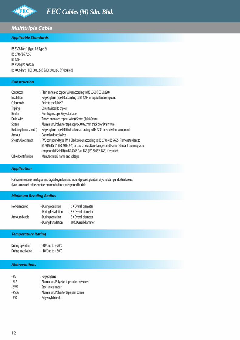
FEC Cables (M) Sdn. Bhd.
12
BS 5308 Part 1 (Type 1 & Type 2)BS 6746/ BS 7655BS 6234BS 6360 (IEC 60228)BS 4066 Part 1 (IEC 60332-1) & IEC 60332-3 (if required)
Construction
Conductor : Plain annealed copper wires according to BS 6360 (IEC 60228)Insulation : Polyethylene type 03 according to BS 6234 or equivalent compoundColour code : Refer to the Table 7Tripling : Cores twisted to triplesBinder : Non-hygroscopic Polyester tapeDrain wire : Tinned annealed copper wire 0.5mm2 (1/0.80mm)Screen : Aluminium/Polyester tape approx. 0.022mm thick over Drain wireBedding (Inner sheath) : Polyethylene type 03 Black colour according to BS 6234 or equivalent compoundArmour : Galvanized steel wiresSheath/Oversheath : PVC compound type TM 1 Black colour according to BS 6746 / BS 7655, Flame retardant to BS 4066 Part 1 (IEC 60332-1) or Low smoke, Non-halogen and Flame retardant thermoplastic compound (LSNHFR) to BS 4066 Part 1&3 (IEC 60332-1&3) if required.Cable Identification : Manufacturer’s name and voltage
Application
Abbreviations
Temperature Rating
Minimum Bending Radius
For transmission of analogue and digital signals in and around process plants in dry and damp industrial areas.(Non-armoured cables : not recommended for underground burial)
Non-armoured - During operation : 6 X Overall diameter - During Installation : 8 X Overall diameterArmoured cable - During operation : 8 X Overall diameter - During Installation : 10 X Overall diameter
During operation : -30°C up to +70°CDuring Installation : -10°C up to +50°C
- PE : Polyethylene- SLA : Aluminium/Polyester tape collective screen- SWA : Steel wire armour- PSLA : Aluminium/Polyester tape pair screen- PVC : Polyvinyl chloride
Applicable Standards
Multitriple Cable

Instrumentation Cables
13
Conductorsize
No.of
pair
Insulationthickness
Nom.(mm)
PE/PVC-SLA(Non-armoured cable)
PE/PE/SWA/PVC-SLA(Armoured cable)
Sheaththickness
Nom.(mm)
OveralldiameterApprox.(mm)
WeightApprox.(kg/km)
Beddingthickness
Nom.(mm)
Diameterover
beddingApprox.(mm)
Armourwire
diameterNom.(mm)
Sheaththickness
Nom.(mm)
OveralldiameterApprox.(mm)
WeightApprox.(kg/km)
0.50mm2
(1/0.80mm)
1235
101520
0.5
0.81.11.11.21.31.31.5
5.59.5
10.512.517.519.522.5
44100115175325435570
0.81.11.11.21.31.31.5
5.69.7
10.312.517.519.522.3
0.90.90.9
1.251.61.61.6
1.31.41.41.51.71.81.9
1014.5151824
26.529.5
195340375570
101011901430
0.50mm2
(7/0.30mm)
1235
101520
0.6
0.81.11.11.21.31.51.7
6.511
11.51420
22.526
51110135200380520680
0.81.11.11.21.31.51.7
6.311
11.614.220
22.725.8
0.90.90.9
1.251.61.62.0
1.31.51.51.61.71.81.9
10.516
16.520
26.529.533.5
220390425650
114013801860
0.75mm2
(1/0.96mm)
1235
101520
0.6
0.81.11.11.21.31.51.7
6.51112
14.520.523.526.5
57125155235445615810
0.81.11.11.21.31.51.7
6.411.211.914.520.523.326.5
0.90.90.9
1.251.61.62.0
1.31.51.51.61.81.81.9
1116
16.520
27.530
34.5
225405450695
123514952015
0.75mm2
(7/0.37mm)
1235
101520
0.6
0.81.11.21.21.31.51.7
6.51213
15.521.524.528
61135175255485670880
0.81.11.21.21.31.51.7
6.711.812.815.321.724.728.1
0.90.9
1.251.251.61.62.0
1.31.51.51.61.81.92.0
1116.518.521
28.531.536
235430575735
131016002160
1.0mm2
(1/1.13mm)
1235
101520
0.6
0.81.11.21.21.31.51.7
71213
15.52225
28.5
68150190285545765
1000
0.81.11.21.21.31.51.7
6.811.912.815.421.824.928.3
0.90.9
1.251.251.61.62.0
1.31.51.51.61.81.92.0
1116.518.521
28.532
36.5
245445595770
137517102305
1.0mm2
(7/0.43mm)
1235
101520
0.6
0.81.21.21.21.51.51.7
713
13.516.523.526.530
72165205305605815
1070
0.81.21.21.21.51.51.7
7.112.813.616.323.626.430.0
0.91.251.251.251.61.62.0
1.31.51.61.61.91.92.0
11.518.519.522
30.533.538
255570640815
150518152450
1.5mm2
(7/0.53mm)
1235
101520
0.6
0.81.21.21.31.51.71.9
814151826
29.533.5
92210265410805
11251475
0.81.21.21.31.51.71.9
7.814
14.918.226
29.533.5
0.91.251.251.61.62.02.0
1.41.61.61.71.92.02.1
12.519.520.52533
37.541.5
290660735
1110179524902995
Table 5 Collective Screen
Multitriple Cable

FEC Cables (M) Sdn. Bhd.
1�
Conductorsize
No.of
pair
Insulationthickness
Nom.(mm)
PE/PVC-TSLA(Non-armoured cable)
PE/PE/SWA/PVC-TSLA(Armoured cable)
Sheaththickness
Nom.(mm)
OveralldiameterApprox.(mm)
WeightApprox.(kg/km)
Beddingthickness
Nom.(mm)
Diameterover
beddingApprox.(mm)
Armourwire
diameterNom.(mm)
Sheaththickness
Nom.(mm)
OveralldiameterApprox.(mm)
WeightApprox.(kg/km)
0.50mm2
(1/0.80mm)
2
3
5
10
15
20
0.5
1.1
1.1
1.2
1.3
1.3
1.5
10.5
11
13.5
19.5
21.5
24.5
110
130
200
375
500
655
1.1
1.1
1.2
1.3
1.3
1.5
10.6
11.2
13.7
19.3
21.5
24.5
0.9
0.9
1.25
1.6
1.6
1.6
1.4
1.5
1.5
1.7
1.8
1.9
15
16
19
26
28.5
31.5
365
415
630
1120
1330
1595
0.50mm2
(7/0.30mm)
2
3
5
10
15
20
0.6
1.1
1.1
1.2
1.3
1.5
1.7
12
12.5
15.5
22
25
28.5
125
150
230
435
600
785
1.1
1.1
1.2
1.3
1.5
1.7
11.9
12.6
15.4
21.8
24.9
28.3
0.9
0.9
1.25
1.6
1.6
2.0
1.5
1.5
1.6
1.8
1.8
1.9
16.5
17.5
21
28.5
31.5
36
425
465
715
1285
1540
2085
0.75mm2
(1/0.96mm)
2
3
5
10
15
20
0.6
1.1
1.2
1.2
1.3
1.5
1.7
12
13
16
22.5
25.5
29
140
180
265
505
695
915
1.1
1.2
1.2
1.3
1.5
1.7
12.1
13.1
15.8
22.4
25.5
29.0
0.9
1.25
1.25
1.6
1.6
2.0
1.5
1.5
1.6
1.8
1.9
2.0
17
18.5
21.5
29
32.5
37
445
595
760
1355
1675
2260
0.75mm2
(7/0.37mm)
2
3
5
10
15
20
0.6
1.2
1.2
1.2
1.5
1.5
1.7
13
14
16.5
24
27
30.5
160
195
285
570
755
990
1.2
1.2
1.2
1.5
1.5
1.7
13
13.8
16.6
24.1
26.9
30.6
1.25
1.25
1.25
1.6
1.6
2.0
1.5
1.5
1.6
1.8
1.9
2.0
18.5
19.5
22.5
31
34
38.5
565
620
805
1475
1775
2400
1.0mm2
(1/1.13mm)
2
3
5
10
15
20
0.6
1.2
1.2
1.2
1.5
1.5
1.7
13
14
17
24
27
31
170
210
315
630
850
1115
1.2
1.2
1.2
1.5
1.5
1.7
13.1
13.9
16.8
24.2
27.1
30.9
1.25
1.25
1.25
1.6
1.6
2.0
1.5
1.5
1.6
1.8
1.9
2.0
18.5
19.5
22.5
31
34
39
585
650
840
1555
1885
2525
1.0mm2
(7/0.43mm)
2
3
5
10
15
20
0.6
1.2
1.2
1.2
1.5
1.5
1.7
13.5
14.5
17.5
25.5
28.5
32.5
185
225
340
675
910
1195
1.2
1.2
1.2
1.5
1.5
1.7
13.7
14.6
17.7
25.6
28.7
32.6
1.25
1.25
1.25
1.6
1.6
2.0
1.5
1.6
1.6
1.9
2.0
2.1
19
20.5
23.5
32.5
36
41
610
690
885
1655
2020
2710
1.5mm2
(7/0.53mm)
2
3
5
10
15
20
0.6
1.2
1.2
1.3
1.5
1.7
1.9
15
16
19.5
28
32
36.5
230
290
450
885
1235
1620
1.2
1.2
1.3
1.5
1.7
1.9
15
16
19.6
28.2
32
36.4
1.25
1.25
1.6
1.6
2.0
2.0
1.6
1.6
1.7
1.9
2.1
2.3
20.5
21.5
26
35
40
45
705
790
1210
1960
2725
3315
Multitriple Cable
Table 6 Individual Triple Screen

Instrumentation Cables
15
Type of triple a-wire b-wire c-wire
1
2
3
4
5
6
Black
Black
Black
Black
Black
Black
White
White
White
White
White
White
Red
Green
Yellow
Brown
Blue
Orange
No. of tripleTypr of triple
center 1st layer 2nd layer
1
2
3
5
10
15
20
1
-
-
-
-
-
1
-
1, 2
1~3
1~5
1, 2
1~4
1~6
-
-
-
-
1~6, 2, 3
1~6, 2~6
1~6, 2~6, 3, 4
Multitriple Cable
Table 8 Electrical characteristics
Conductor sizeElectrical requirements
mm2
(no./mm)0.5
(1/0.80)0.5
(7/0.30)0.75
(1/0.96)0.75
(7/0.37)1.0
(1/1.13)1.0
(7/0.43)1.5
(7/0.53)
Conductor resistance at 20°C (Ω/km) Max. 36.8 36.7 25.0 25.0 18.4 18.5 12.3
Insulation resistance at 20°C (MΩ.km) Min. 5000
Mutual capacitance at 1 kHz (nF/km)
- Collective screen : one-triple cable
: all other cables
- Individual screenMax.
115 75
115
12085
120
Inductance/Resistance ratio, L/R (µH/Ω) Max. 25 40
Voltage test for1 minute
core to core (kV) 1
1core to screen (kV)
Table 7 Colour code (Triple identification)

FEC Cables (M) Sdn. Bhd.
16
Conductor
Insulation
Binder
Drain wire
Screen
Sheath
Multitriple Cable : Cross-Sectional Of Cable
PE/PVC-TSLA INDIVIDUAL TRIPLE SCREEN (NON-ARMOURED CABLE)
Binder
Conductor
Insulation
Binder
Drain wire
Screen
Sheath
PE/PE/SWA/PVC-SLA COLLECTIVE SCREEN (ARMOURED CABLE)
Conductor
Insulation
Binder
Drain wire
Screen
Bending
Armour
Oversheath
PE/PE/SWA/PVC-TSLA INDIVIDUAL TRIPLE SCREEN (ARMOURED CABLE)
Conductor
Insulation
Binder
Binder
Drain wire
Screen
Bedding
Armour
Oversheath
PE/PVC-SLA COLLECTIVE SCREEN (NON-ARMOURED CABLE)

Instrumentation Cables
17
Multipair Cable
BS 5308 Part 2 (Type 1 & Type 2)BS 67�6/ BS 7655BS 6360 (IEC 60228)BS �066 Part 1 (IEC 60332-1) & IEC 60332-3 (if required)
Construction
Conductor : Plain annealed copper wires according to BS 6360 (IEC 60228)Insulation : PVC compound type TI1 according to BS 67�6/ BS 7655Colour code : White and Black (numbering on White core)Pairing : Cores twisted to pairs (two pair cable can be manufactured as a quad for collective screen cables)Binder : Non-hygroscopic Polyester tapeDrain wire : Tinned annealed copper wire 0.5mm2 (1/0.80mm)Screen : Aluminium/Polyester tape approx. 0.022mm thick over Drain wireBedding (Inner sheath) : PVC compaund type TM1 Black colour according to BS 67�6/ BS 7655, Flame retardant to BS �066
Part 1 (IEC 60332-1) or Low smoke, Non-halogen and Flame retardant thermoplastic compound (LSNHFR) to BS �066 Part 1&3 (IEC 60332-1&3) if required.
Armour : Galvanized steel wiresSheath/Oversheath : PVC compound type TM 1 Black colour according to BS 67�6 / BS 7655, Flame retardant to BS �066
Part 1 (IEC 60332-1) or Low smoke, Non-halogen and Flame retardant thermoplastic compound (LSNHFR) to BS �066 Part 1&3 (IEC 60332-1&3) if required.
Cable Identification : Manufacturer’s name and voltage
Application
Abbreviations
Temperature Rating
Minimum Bending Radius
For transmission of analogue and digital signals in and around process plants in dry and damp industrial areas.(Non-armoured cables : not recommended for underground burial)
Non-armoured - During operation : 6 X Overall diameter - During Installation : 8 X Overall diameterArmoured cable - During operation : 8 X Overall diameter - During Installation : 10 X Overall diameter
During operation : -30°C up to +70°CDuring Installation : -10°C up to +50°C
- PVC : Polyvinyl choloride- SLA : Aluminium/Polyester tape collective screen- SWA : Steel wire armour- PSLA : Aluminium/Polyester tape pair screen
Applicable Standards

FEC Cables (M) Sdn. Bhd.
18
Multipair Cable
Conductorsize
No.of
pair
Insulationthickness
Nom.(mm)
PVC/PVC-SLA(Non-armoured cable)
PVC/PVC/SWA/PVC-SLA(Armoured cable)
Sheaththickness
Nom.(mm)
OveralldiameterApprox.(mm)
WeightApprox.(kg/km)
Beddingthickness
Nom.(mm)
Diameterover
beddingApprox.(mm)
Armourwire
diameterNom.(mm)
Sheaththickness
Nom.(mm)
OveralldiameterApprox.(mm)
WeightApprox.(kg/km)
0.50mm2
(1/0.80mm)
1
2
3
5
10
15
20
24
30
0.5
0.8
0.8
0.9
1.1
1.2
1.2
1.3
1.3
1.3
5.5
6
8.5
10.5
14
17
19.5
21
23
39
57
83
130
230
325
425
495
600
0.8
0.8
0.9
1.1
1.2
1.2
1.3
1.3
1.3
5.4
6.1
8.4
10.6
14.2
16.9
19.3
20.8
23.0
0.9
0.9
0.9
0.9
1.25
1.25
1.6
1.6
1.6
1.3
1.3
1.4
1.4
1.6
1.6
1.7
1.7
1.8
10
10.5
13
15
20
22.5
26
27.5
30
195
225
315
420
730
915
1255
1395
1595
0.50mm2
(7/0.30mm)
1
2
3
5
10
15
20
24
30
0.6
0.8
0.8
0.9
1.1
1.2
1.3
1.3
1.3
1.5
6
7
9.5
12
16
19.5
22
24
26.5
45
66
96
150
270
385
495
580
725
0.8
0.8
0.9
1.1
1.2
1.3
1.3
1.3
1.5
6
6.8
9.4
12
16.2
19.4
22
23.9
26.7
0.9
0.9
0.9
0.9
1.25
1.6
1.6
1.6
1.6
1.3
1.3
1.4
1.5
1.6
1.7
1.8
1.8
1.9
10.5
11
14
17
22
26
29
30.5
33.5
205
250
355
485
845
1220
1460
1625
1915
0.75mm2
(1/0.96mm)
1
2
3
5
10
15
20
24
30
0.6
0.8
0.8
0.9
1.1
1.2
1.3
1.3
1.5
1.5
6
7
9.5
12.5
16.5
20
22.5
25
27.5
50
75
105
170
310
450
575
695
850
0.8
0.8
0.9
1.1
1.2
1.3
1.3
1.5
1.5
6.1
7
9.6
12.3
16.6
19.9
22.6
24.9
27.4
0.9
0.9
0.9
0.9
1.25
1.6
1.6
1.6
1.6
1.3
1.3
1.4
1.5
1.6
1.7
1.8
1.8
1.9
10.5
11.5
14
17
22.5
26.5
29.5
31.5
34.5
220
265
370
510
895
1305
1565
1780
2055
0.75mm2
(7/0.37mm)
1
2
3
5
10
15
20
24
30
0.6
0.8
0.8
1.1
1.2
1.3
1.3
1.5
1.5
1.7
6.5
7.5
10.5
13
17.5
21
24.5
26.5
29.5
54
81
125
190
345
490
650
765
955
0.8
0.8
1.1
1.2
1.3
1.3
1.5
1.5
1.7
6.4
7.3
10.6
13.2
17.7
21.1
23.9
26.4
29.1
0.9
0.9
0.9
1.25
1.6
1.6
1.6
1.6
2.0
1.3
1.4
1.4
1.5
1.7
1.8
1.8
1.9
2.0
11
12
15
18.5
24.5
28
31
33.5
37.5
230
280
410
655
1125
1410
1720
1925
2540
Table 9 Collective Screen
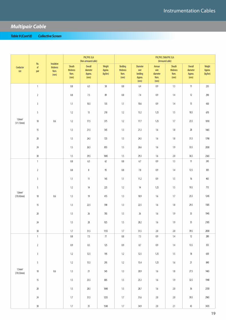
Instrumentation Cables
19
Multipair Cable
Conductorsize
No.of
pair
Insulationthickness
Nom.(mm)
PVC/PVC-SLA(Non-armoured cable)
PVC/PVC /SWA/PVC-SLA(Armoured cable)
Sheaththickness
Nom.(mm)
OveralldiameterApprox.(mm)
WeightApprox.(kg/km)
Beddingthickness
Nom.(mm)
Diameterover
beddingApprox.(mm)
Armourwire
diameterNom.(mm)
Sheaththickness
Nom.(mm)
OveralldiameterApprox.(mm)
WeightApprox.(kg/km)
1.0mm2
(1/1.13mm)
1
2
3
5
10
15
20
24
30
0.6
0.8
0.8
1.1
1.2
1.2
1.3
1.5
1.5
1.5
6.5
7.5
10.5
13
17.5
21.5
24.5
26.5
29.5
58
89
135
210
375
545
725
855
1045
0.8
0.8
1.1
1.2
1.2
1.3
1.5
1.5
1.5
6.4
7.4
10.6
13.2
17.7
21.3
24.5
26.6
29.3
0.9
0.9
0.9
1.25
1.25
1.6
1.6
1.6
1.6
1.3
1.4
1.4
1.5
1.7
1.8
1.8
1.9
2.0
11
12
15
18.5
23.5
28
31.5
33.5
36.5
235
290
430
670
1010
1465
1790
2030
2365
1.0mm2
(7/0.43mm)
1
2
3
5
10
15
20
24
30
0.6
0.8
0.8
1.1
1.2
1.3
1.3
1.5
1.5
1.7
6.5
8
11
14
19
22.5
26
28
31.5
62
95
145
225
415
590
785
925
1155
0.8
0.8
1.1
1.2
1.3
1.3
1.5
1.5
1.7
6.7
7.8
11.2
14
18.9
22.5
26
28.2
31.5
0.9
0.9
0.9
1.25
1.6
1.6
1.6
1.6
2.0
1.3
1.4
1.5
1.5
1.7
1.8
1.9
1.9
2.0
11
12.5
16
19.5
25.5
29.5
33
35
39.5
245
305
465
715
1245
1585
1945
2185
2830
1.5mm2
(7/0.53mm)
1
2
3
5
10
15
20
24
30
0.6
0.8
0.9
1.2
1.2
1.3
1.5
1.5
1.7
1.7
7.5
8.5
12.5
15.5
21
25.5
28.5
31.5
35
77
125
195
295
545
805
1040
1255
1540
0.8
0.9
1.2
1.2
1.3
1.5
1.5
1.7
1.7
7.3
8.7
12.5
15.4
20.9
25.3
28.7
31.6
34.9
0.9
0.9
1.25
1.25
1.6
1.6
1.6
2.0
2.0
1.4
1.4
1.5
1.6
1.8
1.9
2.0
2.0
2.1
12
13.5
18
21
27.5
32.5
36
39.5
43
280
355
630
840
1465
1940
2350
2965
3435
Table 9 (Cont’d) Collective Screen

FEC Cables (M) Sdn. Bhd.
20
Multipair Cable
Conductorsize
No.of
pair
Insulationthickness
Nom.(mm)
PVC/PVC-PSLA(Non-armoured cable)
PVC/PVC/SWA/PVC-PSLA(Armoured cable)
Sheaththickness
Nom.(mm)
OveralldiameterApprox.(mm)
WeightApprox.(kg/km)
Beddingthickness
Nom.(mm)
Diameterover
beddingApprox.(mm)
Armourwire
diameterNom.(mm)
Sheaththickness
Nom.(mm)
OveralldiameterApprox.(mm)
WeightApprox.(kg/km)
0.50mm2
(1/0.80mm)
2
3
5
10
15
20
24
30
0.5
0.9
1.1
1.2
1.2
1.3
1.3
1.5
1.5
9.5
10.5
12.5
17.5
19.5
22
25.5
27
85
110
165
300
405
510
650
760
0.9
1.1
1.2
1.2
1.3
1.3
1.5
1.5
9.4
10.4
12.6
17.5
19.7
22.1
25.6
27.1
0.9
0.9
1.25
1.25
1.6
1.6
1.6
1.6
1.4
1.4
1.5
1.7
1.7
1.8
1.9
1.9
14
15
18
23.5
26.5
29
32.5
34
335
375
590
875
1200
1400
1680
1850
0.50mm2
(7/0.30mm)
2
3
5
10
15
20
24
30
0.6
1.1
1.1
1.2
1.3
1.5
1.5
1.5
1.7
11
11.5
14
20
23
25.5
29
31.5
105
130
190
360
495
625
770
925
1.1
1.1
1.2
1.3
1.5
1.5
1.5
1.7
10.9
11.6
14.2
20.0
22.8
25.5
29.1
31.3
0.9
0.9
1.25
1.6
1.6
1.6
1.6
2.0
1.5
1.5
1.6
1.8
1.8
1.9
1.9
2.1
15.5
16.5
20
27
29.5
32.5
36
39.5
400
435
665
1175
1410
1655
1925
2455
0.75mm2
(1/0.96mm)
2
3
5
10
15
20
24
30
0.6
1.1
1.1
1.2
1.3
1.3
1.5
1.5
1.7
11
12
14.5
20.5
23
26
30
32
115
140
215
405
540
710
875
1055
1.1
1.1
1.2
1.3
1.3
1.5
1.5
1.7
11.2
11.9
14.5
20.5
22.9
26.1
29.8
32.0
0.9
0.9
1.25
1.6
1.6
1.6
1.6
2.0
1.5
1.5
1.6
1.7
1.8
1.9
1.9
2.0
16
16.5
20
27
29.5
33
37
40
410
450
700
1225
1470
1760
2055
2600
0.75mm2
(7/0.37mm)
2
3
5
10
15
20
24
30
0.6
1.1
1.2
1.2
1.3
1.5
1.7
1.7
2.0
12
12.5
15.5
21.5
24.5
28
32
34.5
125
160
235
445
615
800
985
1200
1.1
1.2
1.2
1.3
1.5
1.7
1.7
2.0
11.8
12.7
15.3
21.6
24.6
28.0
31.9
34.5
0.9
1.25
1.25
1.6
1.6
2.0
2.0
2.0
1.5
1.5
1.6
1.8
1.9
2.0
2.0
2.2
16.5
18
21
28.5
31.5
36
40
43
435
585
745
1315
1605
2160
2530
2905
Table 10 Individual Pair Screen

Instrumentation Cables
21
Multipair Cable
Conductorsize
No.of
pair
Insulationthickness
Nom.(mm)
PVC/PVC-PSLA(Non-armoured cable)
PVC/PVC/SWA/PVC-PSLA(Armoured cable)
Sheaththickness
Nom.(mm)
OveralldiameterApprox.(mm)
WeightApprox.(kg/km)
Beddingthickness
Nom.(mm)
Diameterover
beddingApprox.(mm)
Armourwire
diameterNom.(mm)
Sheaththickness
Nom.(mm)
OveralldiameterApprox.(mm)
WeightApprox.(kg/km)
1.0mm2
(1/1.13mm)
2
3
5
10
15
20
24
30
0.6
1.1
1.2
1.2
1.3
1.5
1.7
1.7
2.0
12
13
15.5
22
25
28
32
34.5
135
170
255
485
670
880
1080
1320
1.1
1.2
1.2
1.3
1.5
1.7
1.7
2.0
11.8
12.8
15.4
21.8
24.8
28.2
32.1
34.7
0.9
1.25
1.25
1.6
1.6
2.0
2.0
2.0
1.5
1.5
1.6
1.8
1.9
2.0
2.0
2.2
16.5
18.5
21
28.5
32
36
40
43
435
600
765
1360
1680
2265
2625
3025
1.0mm2
(7/0.43mm)
2
3
5
10
15
20
24
30
0.6
1.2
1.2
1.2
1.3
1.5
1.5
1.7
2.0
12.5
13.5
16
23
26
29.5
34
36.5
155
185
275
525
725
925
1170
1425
1.2
1.2
1.2
1.3
1.5
1.5
1.7
2.0
12.7
13.4
16.2
23.0
26.2
29.4
34.0
36.7
1.25
1.25
1.25
1.6
1.6
1.6
2.0
2.0
1.5
1.5
1.6
1.8
1.9
2.0
2.1
2.2
18
19
22
30
33
36.5
42
45
575
635
810
1455
1780
2115
2825
3225
1.5mm2
(7/0.53mm)
2
3
5
10
15
20
24
30
0.6
1.2
1.2
1.3
1.5
1.7
1.7
2.0
2.0
14
14.5
18
26
29.5
33
38
40.5
185
235
355
700
965
1235
1570
1850
1.2
1.2
1.3
1.5
1.7
1.7
2.0
2.0
13.8
14.7
18.0
25.8
29.3
32.8
38.1
40.4
1.25
1.25
1.6
1.6
2.0
2.0
2.0
2.5
1.6
1.6
1.7
1.9
2.0
2.1
2.2
2.4
19.5
20.5
24.5
33
37.5
41
46.5
50
650
720
1090
1730
2385
2830
3435
4245
Table 10 (Cont’d) Individual Pair Screen
Conductor sizeElectrical requirements
mm2
(no./mm)0.5
(1/0.80)0.5
(7/0.30)0.75
(1/0.96)0.75
(7/0.37)1.0
(1/1.13)1.0
(7/0.43)1.5
(7/0.53)
Conductor resistance at 20°C (Ω/km) Max. 36.8 36.7 25.0 25.0 18.4 18.5 12.3
Insulation resistance at 20°C (MΩ.km) Min. 25
Mutual capacitance at 1kHz (nF/km) Max. 250
Capacitance between any coreor screen at 1kHz (nF/km)
Max. 450
Inductance/Resistance ratio, L/R (µH/Ω) Max. 25 40
Test voltage for1 minute
core to core (kV) 1
1core to screen (kV)
Table 11 Electrical characteristic

FEC Cables (M) Sdn. Bhd.
22
Multipair Cable
Conductor
Insulation
Binder
Drain wire
Screen
Sheath
Multipair CableCross : Sectional Of Cable
PVC/PVC-PSLA INDIVIDUAL PAIR SCREEN (NON-ARMOURED CABLE)
Binder
Conductor
Insulation
Binder
Drain wire
Screen
Sheath
PVC/PVC/SWA/PVC-SLA COLLECTIVE SCREEN (ARMOURED CABLE)
Conductor
Insulation
Binder
Drain wire
Screen
Bedding
Armour
Oversheath
PVC/PVC/SWA/PVC-PSLA INDIVIDUAL PAIR SCREEN (ARMOURED CABLE)
Conductor
Insulation
Binder
Binder
Drain wire
Screen
Bedding
Armour
Oversheath
PVC/PVC-SLA COLLECTIVE SCREEN (NON-ARMOURED CABLE)

Instrumentation Cables
23
Applicable Standards
Multitriple Cable
BS 5308 Part 2 (Type 1 & Type 2)BS 6746 / BS 7655BS 6360 (IEC 60228)BS 4066 Part 1 (IEC60332-1) & IEC 60332-3 (if required)
Construction
Application
Temperature Rating
Abbreviations
Minimum Bending Radius
For transmission of analogue and digital signals in and around process plants in dry and damp industrial areas.(Non-armoured cables : not recommended for underground burial)
Non-armoured cable : During operation : 6 X Overall diameter : During installation : 8 X Overall diameterArmoured cable : During operation : 8 X Overall diameter : During installation : 10 X Overall diameter
During operation : -30°C up to +70°CDuring installation : -10°C up to +50°C
- PVC : Polyvinyl choloride- SLA : Aluminium/Polyester tape collective screen- SWA : Steel wire armour- TSLA : Aluminium/Polyester tape triple screen
Conductor : Plain annealed copper wires according to BS 6360 (IEC 60228)Insulation : PVC compound type TI1 according to BS 67�6/ BS 7655Colour code : White, Black and Red (numbering White core)Tripling : Cores twisted to triples Binder : Non-hygroscopic Polyester tapeDrain wire : Tinned annealed copper wire 0.5mm2 (1/0.80mm)Screen : Aluminium/Polyester tape approx. 0.022mm thick over Drain wireBedding (Inner sheath) : PVC compound type TM1 Black colour according to BS 67�6/ BS 7655, Flame retardant to BS �066
Part 1 (IEC 60332-1) or Low smoke, Non-halogen and Flame retardant thermoplastic compound (LSNHFR) to BS �066 Part 1&3 (IEC 60332-1&3) if required.
Armour : Galvanized Steel wiresSheath/Oversheath : PVC compoun type TM1 Black colour according to BS 67�6/BS 7655, Flame retardant to BS �066 Part
1 (IEC 60332-1) or Low smoke, Non-halogen and Flame retardant thermoplastic Compoun (LSNHFR) to BS �066 Part 1&3 (IEC 60332-1&3 if required.
Cable identification : Manufacturer’s name and voltage
Applicable Standards

FEC Cables (M) Sdn. Bhd.
2�
Conductorsize
No.of
pair
Insulationthickness
Nom.(mm)
PVC/PVC-SLA(Non-armoured cable)
PVC/PVC/SWA/PVC-SLA(Armoured cable)
Sheaththickness
Nom.(mm)
OveralldiameterApprox.(mm)
WeightApprox.(kg/km)
Beddingthickness
Nom.(mm)
Diameterover
beddingApprox.(mm)
Armourwire
diameterNom.(mm)
Sheaththickness
Nom.(mm)
OveralldiameterApprox.(mm)
WeightApprox.(kg/km)
0.50mm2
(1/0.80mm)
1235
101520
0.5
0.81.11.11.21.31.31.5
5.59.5
10.512.517.519.522.5
47105125190360480630
0.81.11.11.21.31.31.5
5.69.7
10.312.517.519.522.3
0.90.90.9
1.251.61.61.6
1.31.41.41.51.71.81.9
1014.5151824
26.529.5
205360395605
107012701535
0.50mm2
(7/0.30mm)
1235
101520
0.6
0.81.11.11.21.31.51.7
6.511
11.51420
22.526
55120150225425590770
0.81.11.11.21.31.51.7
6.311
11.614.220
22.725.8
0.90.90.9
1.251.61.62.0
1.31.51.51.61.71.81.9
10.516
16.520
26.529.533.5
230415455695
122014952010
0.75mm2
(1/0.96mm)
1235
101520
0.6
0.81.11.11.21.31.51.7
6.51112
14.520.523.526.5
61135170255490680895
0.81.11.11.21.31.51.7
6.411.211.914.520.523.326.5
0.90.90.9
1.251.61.62.0
1.31.51.51.61.81.81.9
1116
16.520
27.530
34.5
235430480740
131516102165
0.75mm2
(7/0.37mm)
1235
101520
0.6
0.81.11.21.21.31.51.7
6.51213
15.521.524.528
66145190280535750980
0.81.11.21.21.31.51.7
6.711.812.815.321.724.728.1
0.90.9
1.251.251.61.62.0
1.31.51.51.61.81.92.0
1116.518.521
28.531.536
250460610790
140517302330
1.0mm2
(1/1.13mm)
1235
101520
0.6
0.81.11.21.21.31.51.7
71213
15.52225
28.5
72160205310595835
1100
0.81.11.21.21.31.51.7
6.811.912.815.421.824.928.3
0.90.9
1.251.251.61.62.0
1.31.51.51.61.81.92.0
1116.518.521
28.532
36.5
255470630820
146018352470
1.0mm2
(7/0.43mm)
1235
101520
0.6
0.81.21.21.21.51.51.7
713
13.516.523.526.530
78180225335665905
1190
0.81.21.21.21.51.51.7
7.112.813.616.323.626.430
0.91.251.251.251.61.62.0
1.31.51.61.61.91.92.0
11.518.519.522
30.533.538
265600680870
161519552635
1.5mm2
(7/0.53mm)
1235
101520
0.6
0.81.21.21.31.51.71.9
814151826
29.533.5
100225290445875
12301615
0.81.21.21.31.51.71.9
7.814
14.918.226
29.533.5
0.91.251.251.61.62.02.0
1.41.61.61.71.92.02.1
12.519.520.52533
37.541.5
305695780
1180191526603220
Multitriple Cable
Table 12 Collective Screen

Instrumentation Cables
25
Conductorsize
No.of
pair
Insulationthickness
Nom.(mm)
PVC/PVC-TSLA(Non-armoured cable)
PVC/PVC/SWA/PVC-TSLA(Armoured cable)
Sheaththickness
Nom.(mm)
OveralldiameterApprox.(mm)
WeightApprox.(kg/km)
Beddingthickness
Nom.(mm)
Diameterover
beddingApprox.(mm)
Armourwire
diameterNom.(mm)
Sheaththickness
Nom.(mm)
OveralldiameterApprox.(mm)
WeightApprox.(kg/km)
0.50mm2
(1/0.80mm)
2
3
5
10
15
20
0.5
1.1
1.1
1.2
1.3
1.3
1.5
10.5
11
13.5
19.5
21.5
24.5
105
140
215
405
545
715
1.1
1.1
1.2
1.3
1.3
1.5
10.6
11.2
13.7
19.3
21.5
24.5
0.9
0.9
1.25
1.6
1.6
1.6
1.4
1.5
1.5
1.7
1.8
1.9
15
16
19
26
28.5
31.5
390
440
665
1180
1415
1705
0.50mm2
(7/0.30mm)
2
3
5
10
15
20
0.6
1.1
1.1
1.2
1.3
1.5
1.7
12
12.5
15.5
22
25
28.5
135
165
250
480
665
875
1.1
1.1
1.2
1.3
1.5
1.7
11.9
12.6
15.4
21.8
24.9
28.3
0.9
0.9
1.25
1.6
1.6
2.0
1.5
1.5
1.6
1.8
1.8
1.9
16.5
17.5
21
28.5
31.5
36
450
495
765
1370
1660
2240
0.75mm2
(1/0.96mm)
2
3
5
10
15
20
0.6
1.1
1.2
1.2
1.3
1.5
1.7
12
13
16
22.5
25.5
29
150
190
285
545
760
1000
1.1
1.2
1.2
1.3
1.5
1.7
12.1
13.1
15.8
22.4
25.5
29.0
0.9
1.25
1.25
1.6
1.6
2.0
1.5
1.5
1.6
1.8
1.9
2.0
17
18.5
21.5
29
32.5
37
470
630
810
1440
1790
2415
0.75mm2
(7/0.37mm)
2
3
5
10
15
20
0.6
1.2
1.2
1.2
1.5
1.5
1.7
13
14
16.5
24
27
30.5
170
210
310
620
835
1095
1.2
1.2
1.2
1.5
1.5
1.7
13
13.8
16.6
24.1
26.9
30.6
1.25
1.25
1.25
1.6
1.6
2.0
1.5
1.5
1.6
1.8
1.9
2.0
18.5
19.5
22.5
31
34
38.5
595
660
860
1575
1910
2575
1.0mm2
(1/1.13mm)
2
3
5
10
15
20
0.6
1.2
1.2
1.2
1.5
1.5
1.7
13
14
17
24
27
31
180
225
340
680
925
1215
1.2
1.2
1.2
1.5
1.5
1.7
13.1
13.9
16.8
24.2
27.1
30.9
1.25
1.25
1.25
1.6
1.6
2.0
1.5
1.5
1.6
1.8
1.9
2.0
18.5
19.5
22.5
31
34
39
615
690
890
1650
2015
2695
1.0mm2
(7/0.43mm)
2
3
5
10
15
20
0.6
1.2
1.2
1.2
1.5
1.5
1.7
13.5
14.5
17.5
25.5
28.5
32.5
195
245
370
735
1000
1310
1.2
1.2
1.2
1.5
1.5
1.7
13.7
14.6
17.7
25.6
28.7
32.6
1.25
1.25
1.25
1.6
1.6
2.0
1.5
1.6
1.6
1.9
2.0
2.1
19
20.5
23.5
32.5
36
41
645
730
945
1765
2165
2905
1.5mm2
(7/0.53mm)
2
3
5
10
15
20
0.6
1.2
1.2
1.3
1.5
1.7
1.9
15
16
19.5
28
32
36.5
245
310
485
955
1340
1760
1.2
1.2
1.3
1.5
1.7
1.9
15
16
19.6
28.2
32
36.4
1.25
1.25
1.6
1.6
2.0
2.0
1.6
1.6
1.7
1.9
2.1
2.3
20.5
21.5
26
35
40
45
755
835
1280
2090
2900
3550
Table 13 Individual Triple Screen
Multitriple Cable

FEC Cables (M) Sdn. Bhd.
26
Conductor sizeElectrical requirements
mm2
(no./mm)0.5
(1/0.80)0.5
(7/0.30)0.75
(1/0.96)0.75
(7/0.37)1.0
(1/1.13)1.0
(7/0.43)1.5
(7/0.53)
Conductor resistance at 20°C (Ω/km) Max. 36.8 36.7 25.0 25.0 18.4 18.5 12.3
Insulation resistance at 20°C (MΩ.km) Min. 25
Mutual capacitance at 1kHz (nF/km) Max. 250
Inductance/Resistance ratio, L/R (µH/Ω) Max. 25 40
Test voltage for1 minute
core to core (kV) 1
1core to screen (kV)
Multitriple Cable
Table 14 Electarical characteristics
Conductor
Insulation
Binder
Drain wire
Screen
Sheath Binder
Conductor
Insulation
Binder
Drain wire
Screen
Sheath
PVC/PVC/SWA/PVC-SLA COLLECTIVE SCREEN (ARMOURED CABLE)
Conductor
Insulation
Binder
Drain wire
Screen
Bending
Armour
Oversheath
PVC/PVC/SWA/PVC-TSLA INDIVIDUAL TRIPLE SCREEN (ARMOURED CABLE)
Conductor
Insulation
Binder
Binder
Drain wire
Screen
Bedding
Armour
Oversheath
Multitriple Cable - Cross-Sectional Of Cable
PVC/PVC-SLA COLLECTIVE SCREEN (NON-ARMOURED CABLE) PVC/PVC-TSLA INDIVIDUAL TRIPLE SCREEN (NON-ARMOURED CABLE)

27
Accreditations

FEC Cables (M) Sdn. Bhd.
Factory 1 : Persiaran Raja Muda, �0000 Shah Alam, Selangor Darul Ehsan, Malaysia.(P.O. Box 7006, �0700 Shah Alam) Tel : 603-5519 1110/3/�, 5519 1258, 5519 581�/5/7Fax : 603-5519 1296
Factory 2 : No. 16, Jalan Keluli 2, Bukit Raja Industrial Area, �0150 Klang, Selangor Darul Ehsan, Malaysia.Tel : 603-33�3 5837/9/�0, 33�3 7727Fax : 603-33�3 58�3, 33�3 9262
Sales Office :Persiaran Raja Muda, �0000 Shah Alam, Selangor Darul Ehsan, Malaysia.(P.O. Box 7006, �0700 Shah Alam) Tel : 603-5519 1110 (Hotline)Fax : 603-5519 1296, 5513 8688Website : www.furukawa.com.mye-mail : [email protected]
www.fec.com.my
(7293-W)

FEC Cables (M) Sdn. Bhd.
Fire Resistant Cables

CORPORATEHISTORY
INTRODUCTION OF
COMPANYWhen there is talk of high quality electric wires and cables, the one company that comes to mind is FEC Cables (Malaysia) Sdn. Bhd. FEC is a subsidiary of Permodalan Nasional Berhad and was formerly known as Furukawa Electric Cables (M) Sdn. Bhd. Having established its Shah Alam plant in 1967 on a 7-acre site at the Shah Alam Industrial Estate, Furukawa has come a long way.
The technical collaboration with our Japanese counterpart, Furukawa Japan, has brought about an amazing success for us. In terms of quality, we have climbed the ladders of product manufacturing, steadily and successfully, pushing FEC towards the pinnacle of excellence. Putting our customers’ demands and needs as our number one priority, we opened our second plant in 1995, on a 27-acre freehold land site in Bukit Raja Industrial area, Klang. In our quest for excellence, we equip the plant with the latest technological aids for the manufacture of a wide range of low and medium voltage cables.
The certification of the ISO 9001 for both plants only proves that we do not compromise on quality and customer satisfaction. Our dedicated and hard-working employees are the backbone of our success. This was greatly helped by the state-of-the-art technology equipment which has led us towards excellence.
Moving towards a new century, we pledge to continually strive towards progressive and dynamic growth as FEC Cables continues its efforts in contributing to the development Malaysia.
FEC Cables (M) Sdn. Bhd. was first established in 1967 and was previously known as Furukawa Electric Cables (M) Sdn. Bhd. In all the years until 2003, the company had been under the management and control of Furukawa Electric Co. Ltd. of Japan.
In 2003, the company was renamed FEC Cables (M) Sdn. Bhd. following the acquisition of its major equity stake by Permodalan Nasional Berhad, Malaysia’s government-owned premier multi-billion dollar investment institution.
The Company had started a technical collaboration from world renowned cable manufacturer, The Furukawa Electric Co. Ltd Japan (Furukawa Japan).
FEC Cables has benefited enormously from the technical collaboration and the subsequent technology transfer with Furukawa Japan. FEC Cables inherited from Furukawa Japan not only its advanced technology and technical know-how but also the disciplines of producing quality products using material conforming to the international standards of manufacturing cables.
Today FEC Cables plays a prominent role as a forerunner in the cable industry.
FEC Cables has been actively involved in serving various industrial sectors, namely the power, telecommunications, construction as well as the oil and gas sectors.

Fire Resistant Cables

�
Table Of Contents
INTRODUCTION 5FIRE TEST PHOTO 5APPLICATIONS 6APPLICABLE STANDARDS - SPECIFICATIONS 7KPA FIRE RESISTANT CABLE 9-15 KPA-1 & KPA 2 - NON-ARMOURED CABLES 600/1000 V KPA-1 & KPA 2 - ARMOURED CABLES 600/1000 V
KPA-3 - NON-ARMOURED CABLES 300/500 V FT-8 FIRE RESISTANT CABLE 16-21 FT-8 - NON-ARMOURED CABLES 600/1000 V FT-8 - ARMOURED CABLES 600/1000 V FT-8 - NON-ARMOURED CABLES 300/500 VMIFR FIRE RESISTANT CABLE 22-27 MIFR - NON-ARMOURED CABLES 600/1000 V MIFR - ARMOURED CABLES 600/1000 V MIFR - NON-ARMOURED CABLES �50/750 VTECHNICAL DATA 28

FIRE RESISTANT CABLES
5
INTRODUCTION
ApplicationsThe FEC’s Fire Resistant Cables are specially designed to maintain circuit integrity in a fire, conforming with BS 6387 categories C,W and Z. It’s widely use for the installation of safety systems, including lift, smoke exhaust, smoke and fire shutter, fire alarms, emergency lighting, PA systems, hydrants and emergency power supply which used in wide variety of public access building and industrial complexes. For example project using FEC fire resistant cables are Putrajaya and Petronas Twin Tower.
Quality FEC fire resistant cables are manufactured under an ISO 9001 quality system certified by BVQI. We also obtained approval from other accreditation bodies such as BOMBA, SIRIM, JKR, PETRONAS and PSB of Singapore. This proves that we do not compromise on quality and customer satisfaction. Our policy is to meet the requirements of customers by continually :• Upgrading the skills and productivity of our human resources• Maintaining the equipment and factory in peak form and performance• Sourcing cost effective materials• Improving and effectively implementing our quality management system in accordance to ISO 9001:2000 standard• Maintaining a harmonious workforce which is dedicated and committed to production of quality cables.
We believe in giving the best ! There is no compromise !
Fire Resistant Cable – Keeps a Safety of Human Life…Fire in high rise in urban area are recently becoming a big social problem throughout the world. Major accidents as occurred in the past which have resulted in the deaths of many people would have been avoided if there had been effective fire preventive feature designed and installed to minimize such injuries and damages and to save and protect human life and properties.
FIRE TEST PHOTO
Fire Test Category CWZ (BS6387) And Flame Propagation Test (IEC 60332-3 Cat. A,B,C)
FIRE TEST CATEGORY C FIRE AND WATER TEST CATEGORY W
FIRE AND IMPACT TEST CATEGORY Z
CABLES DURING IEC 60332PART 3 TEST
HistorySince 1985, FEC Cables were the first cable manufacturer to manufacture fire resistant cables in Malaysia. With 20 years of knowledge and experience in designing and manufacturing of Fire Resistant Cables, now we provide complete product range complying with industry standard and applications, including instrumentation, control and low voltage power cables. For safeguarding the human life and as well as protecting the equipment, FEC’s FireResistant Cables when burnt during a fire, produce very low quantities of smoke and acidic gases.

FEC Cables (M) Sdn. Bhd.
6
Lift
Smoke Exhaust Fire Exhaust Equipment
Smoke and Fire Shutter
Emergency Announcing Equipment
Emergency Guide Lamp
Emergency Plug Socket
Hydrant Equipment
Emergency Power Supply
APPLICATIONS

FIRE RESISTANT CABLES
7
APPLICABLE STANDARDS - SPECIFICATIONS
Fire Resistant Test
BS 6387, SS 299 Pt. 1, IEC 60331Specification for performance requirements for cables required to maintain circuit integrity under fire conditions.
Resistant to fire alone (BS 6387, SS 299)Category A - Cables are subjected to fire at 650°C for 3 hoursCategory B - Cables are subjected to fire at 750°C for 3 hoursCategory C - Cables are subjected to fire at 950°C for 3 hours
Note : For IEC 60331, cables are subjected to fire at 750°C for 3 hours. In not less than 12 hours after the test, the cable shall again be energized, and there shall not be any breakdown.
Resistant to fire with waterCategory W - Cables are subjected to fire at 650°C for 15 minutes, then water spray and falme for further 15 minutes.
Resistant to fire with mechanical shock (BS 6387, SS 299)Category X - Cables are subjected to fire at 650°C with mechanical shock for 15 mins.Category Y - Cables are subjected to fire at 750°C with mechanical shock for 15 mins.Category Z - Cables are subjected to fire at 950°C with mechanical shock for 15 mins.
During the test, the flame and test voltage shall be applied continuosly for a period of 3hours and no 3A fuse shall ruptured.
IEC 60332-1Tests on a single vertical insulated wire or cable.
IEC 60332-3Tests for vertical flame spread of vertically mounted bunched wires and cables.
Category A - 7 litres of combustible material per meter shall be bunched on a ladder exposed to flame for �0 minutes.Category B - 3.5 litres of combustible material per meter shall be bunched on a ladder exposed to flame for �0 minutes.Category C - 1.5 litres of combustible material per meter shall be bunched on a ladder exposed to flame for 20 minutes.
The cables specimens are placed vertically next to each other and than exposed to flame for a specific period of time. After the burning has ceased, the charred portion should not exceed a height of 2.5 meters.
Flame Retardant Test
Fire Resistanttested to
IEC 60331/SS 299/
BS 6387 CWZ
Flame Retardanttested to
IEC 60332 - 1&3 Cat. ABC
Zero Halogentested to
IEC 6075� - 1&2
Low SmokeEmissiontested toIEC 6103�
100˚C
50˚C
0˚C
110˚C
TemperatureRange
-25 ~ + 90°C
Acid GasEmission
Anti Termite& Rodent

FEC Cables (M) Sdn. Bhd.
8
APPLICABLE STANDARDS - SPECIFICATION
Smoke Emission Test
Acid Gas Emission Test
IEC 61034Measurement of smoke density of electric cables burning under defined conditions.
A one meter length of sample cable is placed in a 3m smoke chamber. Sample of cable are subjected to the flame of burning alcohol. A smoke is then produced within the chamber is measured by a photocell. The minimum light transmittance is recorded and the minimum value is 60% is acceptable.
General Standards
IEC 60754-1 Determination of the amount of halogen acid gas evolved during combustion of material from cables.
IEC 60754-2Determination of degree of acidity of gases evolved during combustion of materials taken from electric cables by measuring pH and conductivity.
This standard requires the weighted pH value should not be less than �.3 when related to 1 litre of water and the weighted value of conductivity should not exceed 10µS/mm.
IEC 60502-1Power cable with extruded insulation and their accessories for rated voltages from 1 kV up to 30 kV.
BS 6004PVC insulated cables for electrical power and lighting.
Fire Resistanttested to
IEC 60331/SS 299/
BS 6387 CWZ
Flame Retardanttested to
IEC 60332 - 1&3 Cat. ABC
Zero Halogentested to
IEC 6075� - 1&2
Low SmokeEmissiontested toIEC 6103�
100˚C
50˚C
0˚C
110˚C
TemperatureRange
-25 ~ + 90°C
Acid GasEmission
Anti Termite& Rodent

FIRE RESISTANT CABLES
9
FIRE RESISTANT CABLES
9
KPA FIRE RESISTANT CABLE
Cable Construction for KPA-1 & KPA-2
Core Identification
(1) PE Insulated, PVC FR Sheathed - 600/1000V (KPA-1) (2) PE Insulated, LSNHFR Sheathed - 600/1000V (KPA-2)
1. Conductor : Plain Annealed Copper Wires, circular non-compacted or compacted stranded.2. Fire Proof Layer : Mica Tape.3. Insulation : Extruded Polyethylene (PE) �. Filler : Non-hygroscopic fillers ( If necessary).5. Binder Tape : Non-hygroscopic tape.6. Sheath : Extruded Flame Retardant PVC or Low Smoke Non-halogen Flame Retardant (Inner Sheath) Thermoplastic.7. Armouring : Multi-core - Galvanized Steel Wire Single-core - Hard Drawn Aluminium Wire 8. Outer Sheath : Extruded Flame Retardant PVC or Low Smoke Non-halogen Flame Retardant Thermoplastic.
Single-core : Natural or Black2 – core : Red , Black3 – core : Red , Yellow , Blue� – core : Red , Yellow , Blue , Black5 – core and above : Black , White ( Numbering – black printing on white core)
Note : Other colour combination as per requirements. LSNHFR – Low Smoke Non-halogen Flame Retardant KPA-1(750°C) are fully complies to IEC 60331, IEC 60332-1 KPA-1(950°C) are fully complies to IEC 60331, IEC 60332-1, BS 6387, SS 299-1 KPA-2(750°C) are fully complies to IEC 60331, IEC 60332-1, IEC 6103�, IEC 6075� KPA-2(950°C) are fully complies to IEC 60331, IEC 60332-1, BS 6387, SS 299-1, IEC 6103�, IEC 6075�
1
2
3
4
5
67
8

FEC Cables (M) Sdn. Bhd.
10
KPA FIRE RESISTANT CABLE
(3) PE Insulated, PVC FR Sheathed - 300/500V (KPA-3)
Cable Construction for KPA-3
1. Conductor : Plain Annealed Copper Wires, circular non-compacted.2. Fire Proof Layer : Mica Tape.3. Insulation : Extruded Polyethylene (PE).�. Sheath : Extruded Flame Retardant PVC.5. Protective Earth 5.1. Conductor : Plain Annealed Copper Wires, circular non compacted. 5.2. Insulation : Extruded Polyethylene (PE)
Core Indentication
Single-core : Natural or Black 2 – core : Red , Black3 – core : Red , Yellow , Blue� – core : Red , Yellow , Blue , Black5 – core and above : Black , White ( Numbering – black printing on white core)Protective Earth : Green
Note : Other colour combination as per requirements. KPA-3 are fully complies to IEC 60331, IEC 60332-1
123
4
5

FIRE RESISTANT CABLES
11
KPA -1 & KPA-2: NON-ARMOURED CABLES 600/1000V
Table 1 : Single - Core (1C)
Conductor Size(mm²)
Insulation Nom. Thickness (mm)
Insulation Nom. Thickness (mm)
Approx. Overall Diameter (mm)
Approx. Overall Weight (kg/km)
1.5 0.8 1.4 7 60
2.5 0.8 1.4 7.5 75
4 1.0 1.4 8.5 100
6 1.0 1.4 9 120
10 1.0 1.4 9.5 160
16 1.0 1.4 10.5 230
25 1.2 1.4 12 330
35 1.2 1.4 13.5 430
50 1.4 1.4 15 570
70 1.4 1.4 16.5 780
95 1.6 1.5 19 1050
120 1.6 1.5 20.5 1300
150 1.8 1.6 22.5 1550
185 2.0 1.7 24.5 1950
240 2.2 1.8 28 2500
300 2.4 1.9 30.5 3100
400 2.6 2.0 34 4050
500 2.8 2.1 38 5050
630 2.8 2.2 42 6450
800 2.8 2.3 48.5 8100
1000 3.0 2.5 54 10200
Table 2 : Two - Core (2C)
Conductor Size(mm²)
Insulation Nom. Thickness
(mm)
Outer Sheath Nom. Thickness
(mm)
Approx. Overall Diameter
(mm)
Approx. Overall Diameter
(mm)
1.5 0.8 1.8 11.5 130
2.5 0.8 1.8 12.5 160
� 1.0 1.8 1�.5 220
6 1.0 1.8 15.5 280
10 1.0 1.8 17 380
16 1.0 1.8 18.5 520
25 1.2 1.8 22 750
35 1.2 1.8 2� 980
50 1.� 1.8 27 1,250
70 1.� 1.9 30.5 1,700
95 1.6 2.0 35.5 2,350
120 1.6 2.1 38.5 2,900
150 1.8 2.2 �3 3,600
185 2.0 2.� �7 �,�00
2�0 2.2 2.5 53 5,600
300 2.� 2.7 58.5 7,000

FEC Cables (M) Sdn. Bhd.
12
Table 3 : Three-Core (3C)
KPA-1 & KPA-2: NON-ARMOURED CABLES 600/1000V
Conductor Size(mm²)
Insulation Nom. Thickness (mm)
Outer Sheath Nom. Thickness (mm)
Approx. Overall Diameter (mm)
Approx. Overall Weight (kg/km)
1.5 0.8 1.8 12.5 160
2.5 0.8 1.8 13 200
4 1.0 1.8 15.5 280
6 1.0 1.8 16.5 360
10 1.0 1.8 18 500
16 1.0 1.8 20 690
25 1.2 1.8 23.5 1,000
35 1.2 1.8 25.5 1,300
50 1.4 1.8 29 1,700
70 1.4 1.9 32.5 2,400
95 1.6 2.1 38 3,300
120 1.6 2.2 41 4,100
150 1.8 2.3 46 5,000
185 2.0 2.5 50.5 6,300
240 2.2 2.7 57 8,000
300 2.4 2.8 62.5 9,900
Table 4 : Four - Core (4C)
Conductor Size(mm²)
Insulation Nom. Thickness (mm)
Outer Sheath Nom. Thickness (mm)
Approx. Overall Diameter (mm)
Approx. Overall Weight (kg/km)
1.5 0.8 1.8 13.5 200
2.5 0.8 1.8 14.5 250
4 1.0 1.8 16.5 350
6 1.0 1.8 18 450
10 1.0 1.8 19.5 630
16 1.0 1.8 22 890
25 1.2 1.8 25.5 1,300
35 1.2 1.8 28.5 1,700
50 1.4 1.9 32 2,300
70 1.4 2.0 36.5 3,150
95 1.6 2.2 42 4,300
120 1.6 2.3 46 5,400
150 1.8 2.5 51.5 6,600
185 2.0 2.6 56 8,200
240 2.2 2.9 63.5 10,400
300 2.4 3.1 70 13,100

FIRE RESISTANT CABLES
13
KPA-1 & KPA-2: ARMOURED CABLES 600/1000V
Table 5 : Single - Core (1C)
Conductor Size(mm²)
Insulation Nom. Thickness (mm)
Inner Sheath Nom. Thickness (mm)
Approx. Diameter Over Inner Sheath(mm)
Armour Wire Nom. Diameter (mm)
Outer Sheath Nom. Thickness (mm)
Approx. Overall Diameter (mm)
Approx. Overall Weight (kg/km)
1.5 0.8 1.0 6 0.90 1.8 11.5 150
2.5 0.8 1.0 6.5 0.90 1.8 12 170
4 1.0 1.0 7.5 0.90 1.8 13 210
6 1.0 1.0 8 0.90 1.8 13.5 240
10 1.0 1.0 8.5 0.90 1.8 14 290
16 1.0 1.0 9.5 0.90 1.8 15 360
25 1.2 1.0 11 0.90 1.8 16.5 480
35 1.2 1.0 12 1.25 1.8 18.5 630
50 1.4 1.0 13.5 1.25 1.8 20 790
70 1.4 1.0 15.5 1.25 1.8 21.5 1,000
95 1.6 1.0 17.5 1.60 1.8 24.5 1,350
120 1.6 1.0 19 1.60 1.8 26 1,550
150 1.8 1.0 21 1.60 1.8 28 1,900
185 2.0 1.0 23 1.60 1.9 30 2,300
240 2.2 1.0 26 1.60 1.9 33 2,850
300 2.4 1.0 28.5 2.00 2.1 36.5 3,600
400 2.6 1.2 32 2.00 2.2 40.5 4,600
500 2.8 1.2 36 2.00 2.3 44.5 5,650
630 2.8 1.2 39.5 2.50 2.4 49.5 7,250
800 2.8 1.4 46.5 2.50 2.6 57 9,200
1000 3.0 1.4 51.5 2.50 2.7 62 11,400
Table 6 : Two - Core (2C)
Conductor Size(mm²)
Insulation Nom. Thickness (mm)
Inner Sheath Nom. Thickness (mm)
Approx. Diameter Over Inner Sheath
(mm)
Armour Wire Nom. Diameter (mm)
Outer Sheath Nom. Thickness (mm)
Approx. Overall Diameter (mm)
Approx. Overall Weight (kg/km)
1.5 0.8 1.0 10.5 0.90 1.8 15.5 400
2.5 0.8 1.0 11.5 0.90 1.8 16.5 450
4 1.0 1.0 13 0.90 1.8 18 550
6 1.0 1.0 14.5 1.25 1.8 20 730
10 1.0 1.0 15.5 1.25 1.8 21.5 870
16 1.0 1.0 17.5 1.25 1.8 23.5 1,050
25 1.2 1.0 20.5 1.60 1.8 27 1,500
35 1.2 1.0 23 1.60 1.8 29.5 1,800
50 1.4 1.0 26 1.60 1.9 32.5 2,200
70 1.4 1.0 29 2.00 2.0 36.5 3,000
95 1.6 1.2 34 2.00 2.2 42 3,900
120 1.6 1.2 37 2.00 2.3 45 4,600
150 1.8 1.2 41 2.50 2.4 50.5 5,800
185 2.0 1.4 45 2.50 2.6 55 7,000
240 2.2 1.4 51 2.50 2.8 61 8,500
300 2.4 1.6 56.5 2.50 2.9 67 10,200

FEC Cables (M) Sdn. Bhd.
1�
KPA-1 & KPA-2: ARMOURED CABLES 600/1000V
Table 7 : Three-Core (3C)
Conductor Size(mm²)
Insulation Nom. Thickness (mm)
Inner Sheath Nom. Thickness (mm)
Approx. Diameter Over Inner Sheath(mm)
Armour Wire Nom. Diameter (mm)
Outer Sheath Nom. Thickness (mm)
Approx. Overall Diameter (mm)
Approx. Overall Weight (kg/km)
1.5 0.8 1.0 11 0.90 1.8 16 440
2.5 0.8 1.0 12 0.90 1.8 17 500
4 1.0 1.0 14 1.25 1.8 19.5 720
6 1.0 1.0 15 1.25 1.8 21 830
10 1.0 1.0 16.5 1.25 1.8 22.5 1,000
16 1.0 1.0 19 1.25 1.8 24.5 1,200
25 1.2 1.0 22 1.60 1.8 28.5 1,800
35 1.2 1.0 24.5 1.60 1.8 31 2,200
50 1.4 1.0 27.5 1.60 2.0 34.5 2,800
70 1.4 1.2 31.5 2.00 2.1 39.5 3,900
95 1.6 1.2 36.5 2.00 2.2 44.5 5,000
120 1.6 1.2 39.5 2.00 2.3 48 5,900
150 1.8 1.4 44.5 2.50 2.5 54 7,500
185 2.0 1.4 48.5 2.50 2.7 58.5 9,000
240 2.2 1.6 55 2.50 2.9 65.5 11,100
300 2.4 1.6 60.5 2.50 3.1 71.5 13,300
Table 8 : Four - Core (4C)
Conductor Size(mm²)
Insulation Nom. Thickness (mm)
Inner Sheath Nom. Thickness (mm)
Approx. Diameter Over Inner Sheath(mm)
Armour Wire Nom. Diameter (mm)
Outer Sheath Nom. Thickness (mm)
Approx. Overall Diameter (mm)
Approx. Overall Weight (kg/km)
1.5 0.8 1.0 12 0.90 1.8 17 500
2.5 0.8 1.0 13 0.90 1.8 18 570
4 1.0 1.0 15.5 1.25 1.8 21 840
6 1.0 1.0 16.5 1.25 1.8 22.5 970
10 1.0 1.0 18.5 1.25 1.8 24 1,200
16 1.0 1.0 21 1.60 1.8 27 1,600
25 1.2 1.0 24.5 1.60 1.8 31 2,200
35 1.2 1.0 27 1.60 1.9 33.5 2,700
50 1.4 1.2 31 2.00 2.1 39 3,700
70 1.4 1.2 35 2.00 2.2 43 4,800
95 1.6 1.2 40.5 2.50 2.4 50 6,600
120 1.6 1.4 44.5 2.50 2.5 54 7,900
150 1.8 1.4 49.5 2.50 2.7 59.5 9,400
185 2.0 1.6 54.5 2.50 2.8 64.5 11,200
240 2.2 1.6 61 2.50 3.1 72 13,900
300 2.4 1.6 67.5 3.15 3.3 80 17,700

FIRE RESISTANT CABLES
15
KPA -3: NON-ARMOURED CABLES 300/500V
Table 9
No of CoreConductor Size
(mm²) Insulation Nom. Thickness
(mm)Outer Sheath Nom. Thickness
(mm)Approx. Overall Diameter
(mm)Approx. Overall Weight
(kg/km)
1C1.52.54
0.55 0.54
4.55.5
254055
2C1.52.54
0.55 0.578
9.5
70100140
3C1.52.54
0.55 0.57.59
10
90130180
4C1.52.54
0.55 0.58.59.511
110160230
2C + P.E1.52.54
0.55 0.57.59
10
90130190
3C + P.E1.52.54
0.55 0.58.59.511
110160240
4C + P.E1.52.54
0.55 0.59.5
10.512
130200290
P.E : Protective Earth core
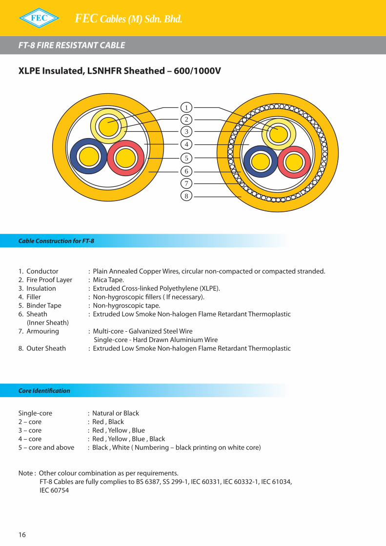
FEC Cables (M) Sdn. Bhd.
16
FT-8 FIRE RESISTANT CABLE
Cable Construction for FT-8
1. Conductor : Plain Annealed Copper Wires, circular non-compacted or compacted stranded.2. Fire Proof Layer : Mica Tape.3. Insulation : Extruded Cross-linked Polyethylene (XLPE).�. Filler : Non-hygroscopic fillers ( If necessary).5. Binder Tape : Non-hygroscopic tape.6. Sheath : Extruded Low Smoke Non-halogen Flame Retardant Thermoplastic (Inner Sheath) 7. Armouring : Multi-core - Galvanized Steel Wire Single-core - Hard Drawn Aluminium Wire 8. Outer Sheath : Extruded Low Smoke Non-halogen Flame Retardant Thermoplastic
Core Identification
Single-core : Natural or Black2 – core : Red , Black3 – core : Red , Yellow , Blue� – core : Red , Yellow , Blue , Black5 – core and above : Black , White ( Numbering – black printing on white core)
Note : Other colour combination as per requirements. FT-8 Cables are fully complies to BS 6387, SS 299-1, IEC 60331, IEC 60332-1, IEC 6103�, IEC 6075�
1
3
4
5
6
7
8
2
XLPE Insulated, LSNHFR Sheathed – 600/1000V
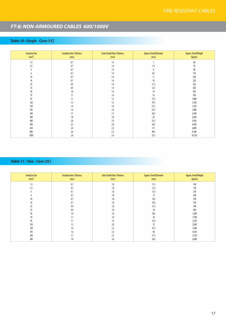
FIRE RESISTANT CABLES
17
FT-8: NON-ARMOURED CABLES 600/1000V
Conductor Size(mm²)
Insulation Nom. Thickness (mm)
Outer Sheath Nom. Thickness (mm)
Approx. Overall Diameter (mm)
Approx. Overall Weight (kg/km)
1.52.546
10162535507095
120150185240300400500630800
1000
0.70.70.70.70.70.70.90.91.01.11.11.21.41.61.71.82.02.22.42.62.8
1.41.41.41.41.41.41.41.41.41.41.51.51.61.61.71.81.92.02.22.32.4
77.58
8.59
1011.512.51416
17.519.521.523.526.529
32.536.541
48.553.5
607090
110160220320420550760
1,0001,2501,5501,9002,4503,0503,9504,9506,4008,100
10,150
Table 10 : Single - Core (1C)
Table 11 : Two - Core (2C)
Conductor Size(mm²)
Insulation Nom. Thickness (mm)
Outer Sheath Nom. Thickness (mm)
Approx. Overall Diameter (mm)
Approx. Overall Weight (kg/km)
1.52.546
10162535507095
120150185240300
0.70.70.70.70.70.70.90.91.01.11.11.21.41.61.71.8
1.81.81.81.81.81.81.81.81.81.81.92.02.22.32.52.6
11.512.513.515
16.518.521.524
26.530
33.537
41.546
51.556.5
140170210260370510740960
1,2001,7002,2502,8503,5004,3505,5506,900
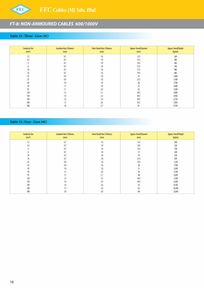
FEC Cables (M) Sdn. Bhd.
18
FT-8: NON-ARMOURED CABLES 600/1000V
Table 12 : Three - Core (3C)
Table 13 : Four - Core (4C)
Conductor Size(mm²)
Insulation Nom. Thickness (mm)
Outer Sheath Nom. Thickness (mm)
Approx. Overall Diameter (mm)
Approx. Overall Weight (kg/km)
1.52.546
10162535507095
120150185240300
0.70.70.70.70.70.70.90.91.01.11.11.21.41.61.71.8
1.81.81.81.81.81.81.81.81.81.92.02.12.32.42.62.7
12.513.514.515.517.519.523
25.5283236
39.544.549.555.561
160200260340480680
1,0001,3001,7002,4003,2004,0004,9506,1507,8509,750
Conductor Size(mm²)
Insulation Nom. Thickness (mm)
Outer Sheath Nom. Thickness (mm)
Approx. Overall Diameter (mm)
Approx. Overall Weight (kg/km)
1.52.546
10162535507095
120150185240300
0.70.70.70.70.70.70.90.91.01.11.11.21.41.61.71.8
1.81.81.81.81.81.81.81.81.82.02.12.32.42.62.83.0
13.514.515.51719
21.525.528313640
44.549.5556268
200250330420610870
1,2501,7002,2003,1004,2005,3006,5008,100
10,30012,850

FIRE RESISTANT CABLES
19
FT-8: ARMOURED CABLES 600/1000V
Table 14 : Single - Core (1C)
Conductor Size(mm²)
Insulation Nom. Thickness (mm)
Inner Sheath Nom. Thickness (mm)
Approx. Diameter Over Inner Sheath(mm)
Armour Wire Nom. Diameter (mm)
Outer Sheath Nom. Thickness (mm)
Approx. Overall Diameter (mm)
Approx. Overall Weight (kg/km)
1.52.546
10162535507095
120150185240300400500630800
1000
0.70.70.70.70.70.70.90.91.01.11.11.21.41.61.71.82.02.22.42.62.8
1.01.01.01.01.01.01.01.01.01.01.01.01.01.01.01.01.21.21.21.41.4
5.56
6.57.589
10.511.513
14.516.51820222527
30.534.538.54651
0.900.900.900.900.900.900.900.901.251.251.251.601.601.601.601.602.002.002.002.502.50
1.81.81.81.81.81.81.81.81.81.81.81.81.81.81.91.92.12.22.32.52.7
1111.512.513
13.514.516171921
22.525272932
34.53943
47.556
61.5
150170200230280350470580760
1,0001,2501,5501,8502,3002,8503,4504,5505,6507,1009,150
11,400
Table 15 : Two - Core (2C)
Conductor Size
(mm²)
Insulation Nom. Thickness (mm)
Inner Sheath Nom. Thickness (mm)
Approx. Diameter Over Inner Sheath
(mm)
Armour Wire Nom. Diameter (mm)
Outer Sheath Nom. Thickness (mm)
Approx. Overall Diameter (mm)
Approx. Overall Weight (kg/km)
1.52.546
10162535507095
120150185240300
0.70.70.70.70.70.70.90.91.01.11.11.21.41.61.71.8
1.01.01.01.01.01.01.01.01.01.01.21.21.21.41.41.6
10.511.512.513.515.517.520.522.525
28.532.535.540
44.549.555
0.900.900.900.901.251.251.601.601.601.602.002.002.002.502.502.50
1.81.81.81.81.81.81.81.81.82.02.12.22.32.52.72.8
15.516.517.518.521232729
31.535.540.54448546065
400450520600840
1,0001,4501,7502,1502,7503,7504,5005,3006,8508,300
10,000

FEC Cables (M) Sdn. Bhd.
20
FT-8: ARMOURED CABLES 600/1000V
Table 16 : Three - Core (3C)
Conductor Size(mm²)
Insulation Nom. Thickness (mm)
Inner Sheath Nom. Thickness (mm)
Approx. Diameter Over Inner Sheath
(mm)
Armour Wire Nom. Diameter (mm)
Outer Sheath Nom. Thickness (mm)
Approx. Overall Diameter (mm)
Approx. Overall Weight (kg/km)
1.52.546
10162535507095
120150185240300
0.70.70.70.70.70.70.90.91.01.11.11.21.41.61.71.8
1.01.01.01.01.01.01.01.01.01.01.21.21.41.41.61.6
111213
14.516.518.521.52427
30.5353843
47.553.559
0.900.900.901.251.251.251.601.601.602.002.002.002.502.502.502.50
1.81.81.81.81.81.81.81.81.92.02.22.32.52.62.83.0
16171820222428
30.533.538.543
46.553
57.564
69.5
440500590790990
1,2001,8002,2002,7003,7504,8005,7507,4008,850
10,90013,100
Table 17 : Four - Core (4C)
Conductor Size(mm²)
Insulation Nom. Thickness (mm)
Inner Sheath Nom. Thickness (mm)
Approx. Diameter Over Inner Sheath
(mm)
Armour Wire Nom. Diameter (mm)
Outer Sheath Nom. Thickness (mm)
Approx. Overall Diameter (mm)
Approx. Overall Weight (kg/km)
1.52.546
10162535507095
120150185240300
0.70.70.70.70.70.70.90.91.01.11.11.21.41.61.71.8
1.01.01.01.01.01.01.01.01.01.21.21.41.41.41.61.6
1213
14.51618
20.524
26.530
34.538.5434853
59.565.5
0.900.901.251.251.251.601.601.601.602.002.002.502.502.502.502.50
1.81.81.81.81.81.81.81.92.02.22.32.52.62.83.03.2
171820
21.523.527
30.533.536.542.547
52.558
63.570.576.5
500570780920
1,1501,6002,1502,7003,3004,7006,0007,7009,150
11,10013,65016,550

FIRE RESISTANT CABLES
21
FT-8: NON-ARMOURED CABLES 300/500V
Table 18
P.E : Protective Earth core
No of Core Conductor Size (mm²)
Insulation Nom. Thickness (mm)
Outer Sheath Nom. Thickness (mm)
Approx.Overall Diameter (mm)
Approx. Overall Weight (kg/km)
1C1.52.54
0.55 0.54.55
5.5
354560
2C1.52.54
0.55 0.59
1011
85100140
3C1.52.54
0.55 0.59.5
10.512
100140190
4C1.52.54
0.55 0.510.511.513
130170250
2C + P.E1.52.54
0.55 0.59.5
10.512
100130190
3C + P.E1.52.54
0.55 0.510.511.513
130170240
4C + P.E1.52.54
0.55 0.511.513
14.5
160210300

FEC Cables (M) Sdn. Bhd.
22
MIFR FIRE RESISTANT CABLE
Cable Construction for MIFR
1. Conductor : Plain Annealed Copper Wires, circular non-compacted or compacted stranded.2. Fire Proof Layer : Mica Tape.3. Insulation : Extruded Flame Retardant Cross-linked Polyethylene (XLPEFR).�. Filler : Non-hygroscopic fillers (If necessary).5. Binder Tape : Non-hygroscopic tape.6. Sheath : Extruded Low Smoke Non-halogen Flame Retardant Mineral Filled compound. (Inner Sheath) 7. Armouring : Multi-core - Galvanized Steel Wire Single-core - Hard Drawn Aluminium Wire 8. Outer Sheath : Extruded Low Smoke Non-halogen Flame Retardant Mineral Filled compound.
Core Identification
Single-core : Natural or Black2 – core : Red , Black3 – core : Red , Yellow , Blue� – core : Red , Yellow , Blue , Black5 – core and above : Black , White ( Numbering – black printing on white core)
Note : Other colour combination as per requirements. MIFR Cables are fully complies to BS 6387, SS 299-1, IEC 60331, IEC 60332-3(A,B,C), IEC 60332-1, IEC 6103�, IEC 6075� For �50/750V Cables, the insulation colour as per requirements.
1
3
4
5
6
7
8
2
XLPEFR Insulated, LSNHFR Sheathed – 600/1000VXLPEFR Insulated, Non-Sheathed Cables – 450/750V

FIRE RESISTANT CABLES
23
MIFR: NON-ARMOURED CABLES 600/1000V
Table 19 : Single - Core (1C)
Conductor Size(mm²)
Insulation Nom. Thickness (mm)
Outer Sheath Nom. Thickness (mm)
Approx. Overall Diameter (mm)
Approx. Overall Weight (kg/km)
1.52.546
10162535507095
120150185240300400500630800
1000
0.70.70.70.70.70.70.90.91.01.11.11.21.41.61.71.82.02.22.42.62.8
1.41.41.41.41.41.41.41.41.41.41.51.51.61.61.71.81.92.02.22.32.4
7.58
8.59
9.510.51213
14.516.51820222427
29.53337
41.54954
7585
100130180240350450590810
1,0501,3001,6002,0002,5503,2004,1005,1506,6008,350
10,500
Table 20 : Two - Core (2C)
Conductor Size(mm²)
Insulation Nom. Thickness (mm)
Outer Sheath Nom. Thickness (mm)
Approx. Overall Diameter (mm)
Approx. Overall Weight (kg/km)
1.52.546
10162535507095
120150185240300
0.70.70.70.70.70.70.90.91.01.11.11.21.41.61.71.8
1.81.81.81.81.81.81.81.81.81.81.92.02.22.32.52.6
1212.513.515161821
23.526
29.533
36.541
45.551
56.5
160190230290390540780
1,0001,2501,7502,3502,9003,6004,5005,7507,100

FEC Cables (M) Sdn. Bhd.
2�
MIFR: NON-ARMOURED CABLES 600/1000V
Table 21 : Three - Core (3C)
Conductor Size(mm²)
Insulation Nom. Thickness (mm)
Outer Sheath Nom. Thickness (mm)
Approx. Overall Diameter (mm)
Approx. Overall Weight (kg/km)
1.52.546
10162535507095
120150185240300
0.70.70.70.70.70.70.90.91.01.11.11.21.41.61.71.8
1.81.81.81.81.81.81.81.81.81.92.02.12.32.42.62.7
12.513.514.515.517
19.522.525
27.532
35.539.544.54955
60.5
190230300370510720
1,0501,3501,7502,4503,3004,1505,1006,4008,100
10,050
Table 22 : Four - Core (4C)
Conductor Size(mm²)
Insulation Nom. Thickness (mm)
Outer Sheath Nom. Thickness (mm)
Approx. Overall Diameter (mm)
Approx. Overall Weight (kg/km)
1.52.546
10162535507095
120150185240300
0.70.70.70.70.70.70.90.91.01.11.11.21.41.61.71.8
1.81.81.81.81.81.81.81.81.82.02.12.32.42.62.83.0
13.514.515.517192125
27.530.535.539.54449
54.561.567.5
230280370470650920
1,3501,7502,3003,2504,3505,4506,7008,400
10,65013,250
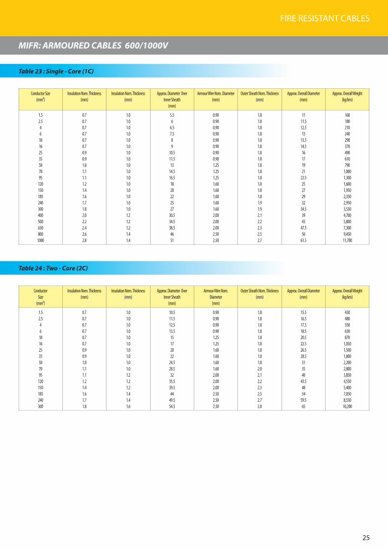
FIRE RESISTANT CABLES
25
MIFR: ARMOURED CABLES 600/1000V
Table 23 : Single - Core (1C)
Conductor Size(mm²)
Insulation Nom. Thickness (mm)
Insulation Nom. Thickness (mm)
Approx. Diameter Over Inner Sheath
(mm)
Armour Wire Nom. Diameter (mm)
Outer Sheath Nom. Thickness (mm)
Approx. Overall Diameter (mm)
Approx. Overall Weight (kg/km)
1.52.546
10162535507095
120150185240300400500630800
1000
0.70.70.70.70.70.70.90.91.01.11.11.21.41.61.71.82.02.22.42.62.8
1.01.01.01.01.01.01.01.01.01.01.01.01.01.01.01.01.21.21.21.41.4
5.56
6.57.589
10.511.513
14.516.51820222527
30.534.538.54651
0.900.900.900.900.900.900.900.901.251.251.251.601.601.601.601.602.002.002.002.502.50
1.81.81.81.81.81.81.81.81.81.81.81.81.81.81.91.92.12.22.32.52.7
1111.512.513
13.514.516171921
22.525272932
34.53943
47.556
61.5
160180210240290370490610790
1,0001,3001,6001,9502,3502,9503,5504,7005,8007,3009,450
11,700
Table 24 : Two - Core (2C)
Conductor Size
(mm²)
Insulation Nom. Thickness (mm)
Insulation Nom. Thickness (mm)
Approx. Diameter Over Inner Sheath
(mm)
Armour Wire Nom. Diameter
(mm)
Outer Sheath Nom. Thickness (mm)
Approx. Overall Diameter (mm)
Approx. Overall Weight (kg/km)
1.52.546
10162535507095
120150185240300
0.70.70.70.70.70.70.90.91.01.11.11.21.41.61.71.8
1.01.01.01.01.01.01.01.01.01.01.21.21.21.41.41.6
10.511.512.513.515172022
24.528.532
35.539.544
49.554.5
0.900.900.900.901.251.251.601.601.601.602.002.002.002.502.502.50
1.81.81.81.81.81.81.81.81.82.02.12.22.32.52.72.8
15.516.517.518.520.522.526.528.5313540
43.54854
59.565
430480550630870
1,0501,5001,8002,2002,8003,8504,5505,4007,0508,550
10,200
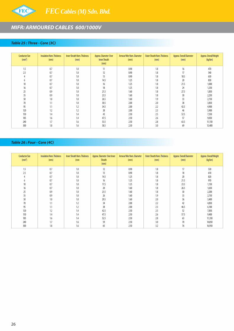
FEC Cables (M) Sdn. Bhd.
26
MIFR: ARMOURED CABLES 600/1000V
Table 25 : Three - Core (3C)
Conductor Size(mm²)
Insulation Nom. Thickness (mm)
Inner Sheath Nom. Thickness (mm)
Approx. Diameter Over Inner Sheath
(mm)
Armour Wire Nom. Diameter (mm)
Outer Sheath Nom. Thickness (mm)
Approx. Overall Diameter (mm)
Approx. Overall Weight (kg/km)
1.52.546
10162535507095
120150185240300
0.70.70.70.70.70.70.90.91.01.11.11.21.41.61.71.8
1.01.01.01.01.01.01.01.01.01.01.21.21.41.41.61.6
111213
14.51618
21.523.526.530.534.53843
47.553.558.5
0.900.900.901.251.251.251.601.601.602.002.002.002.502.502.502.50
1.81.81.81.81.81.81.81.81.92.02.22.32.52.62.83.0
1617
18.520
21.524
27.5303338
42.546
52.557
63.569
470540630830
1,0001,2501,8502,2502,7503,8504,9005,9007,5509,050
11,15013,400
Table 26 : Four - Core (4C)
Conductor Size(mm²)
Insulation Nom. Thickness (mm)
Inner Sheath Nom. Thickness (mm
Approx. Diameter Over Inner Sheath(mm)
Armour Wire Nom. Diameter (mm)
Outer Sheath Nom. Thickness (mm)
Approx. Overall Diameter (mm)
Approx. Overall Weight (kg/km)
1.52.546
10162535507095
120150185240300
0.70.70.70.70.70.70.90.91.01.11.11.21.41.61.71.8
1.01.01.01.01.01.01.01.01.01.21.21.41.41.41.61.6
1213
14.516
17.520
23.526
29.53438
42.547.552.55965
0.900.901.251.251.251.601.601.601.602.002.002.502.502.502.502.50
1.81.81.81.81.81.81.81.92.02.22.32.52.62.83.03.2
171820
21.523.526.530333642
46.552
57.5637076
530610820970
1,1501,6502,2002,7503,4004,8506,1007,8509,400
11,35014,05016,950
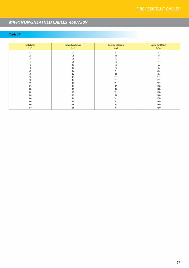
FIRE RESISTANT CABLES
27
MIFR: NON-SHEATHED CABLES 450/750V
Table 27
Conductor Size(mm²)
Insulation Nom. Thickness (mm)
Approx. Overall Diameter (mm)
Approx. Overall Weight (kg/km)
1.52.546
10162535507095
120150185240300400500630
0.70.80.80.81.01.01.21.21.41.41.61.61.82.02.22.42.62.82.8
44.55.05.56.57.59
1011.513.515.51719
20.524
26.529.53337
25405575
120180280380510710980
1,2001,4501,8502,4003,0003,8504,8506,200

FEC Cables (M) Sdn. Bhd.
28
TECHNICAL DATA
Electrical Characteristics For Single Core Cable
Cond. Size(mm²)
Conductor Resistance (ohm/km) Reactance at 50 Hz (ohm/km) Current Rating in Air at 40 °C (A) Short-circuit Current (kA)
D.C at 20 °C A.C at 90°c Flat TrefoilFlat
Trefoil 1 sec. 2 sec.2 cables 3 cables
1.5 12.1 15.4 0.169 0.154 27 23 20 0.20 0.15
2.5 7.41 9.45 0.158 0.142 38 32 30 0.35 0.25
4 4.61 5.88 0.147 0.133 52 44 43 0.57 0.40
6 3.08 3.93 0.139 0.124 65 56 55 0.85 0.61
10 1.83 2.33 0.132 0.117 88 77 75 1.43 1.01
16 1.15 1.47 0.123 0.109 115 100 99 2.28 1.62
25 0.727 0.927 0.118 0.104 155 135 130 3.57 2.53
35 0.524 0.669 0.113 0.0989 190 170 165 5.00 3.54
50 0.387 0.494 0.109 0.0948 230 205 200 7.15 5.06
70 0.268 0.342 0.106 0.0916 290 265 255 10.0 7.08
95 0.193 0.247 0.102 0.0877 360 325 315 13.5 9.61
120 0.153 0.196 0.103 0.0887 415 380 370 17.1 12.1
150 0.124 0.160 0.102 0.0879 480 440 430 21.4 15.2
185 0.0991 0.128 0.101 0.0864 555 510 495 26.4 18.7
240 0.0754 0.0988 0.0993 0.0848 660 615 595 34.3 24.3
300 0.0601 0.0801 0.0979 0.0834 760 710 690 42.9 30.3
400 0.0470 0.0643 0.0976 0.0830 940 830 805 57.2 40.5
500 0.0366 0.0521 0.0968 0.0823 1010 960 930 71.5 50.6
630 0.0283 0.0428 0.0952 0.0807 1170 1110 1080 90.0 63.7
800 0.0221 0.0363 0.0932 0.0787 1360 1300 1260 114 81
1000 0.0176 0.0317 0.0920 0.0775 1510 1450 1400 143 101
Voltage Drop Per Ampere Per Meter For Single Core Cable
Cond. Size (mm²) Two cables Three cables, three phase A.C Four cables, three phase A.C
D.C (mV) Single phase A.C (mV) Flat (mV) Trefoil (mV) Flat (mV) Trefoil (mV)
1.5 30.0 30.0 26.0 26.7 15.0 26.7
2.5 18.0 18.0 16.0 16.3 9.4 16.3
4 11.7 11.7 10.1 10.1 5.9 10.1
6 7.83 7.84 6.8 6.8 3.92 6.8
10 6.06 4.66 4.03 4.04 2.32 4.04
16 2.93 2.94 2.54 2.54 1.47 2.54
25 1.84 1.86 1.61 1.61 0.933 1.61
35 1.34 1.35 1.18 1.16 0.678 1.16
50 0.986 1.01 0.875 0.860 0.505 0.860
70 0.682 0.716 0.620 0.599 0.357 0.599
95 0.491 0.533 0.463 0.435 0.266 0.435
120 0.390 0.443 0.383 0.349 0.220 0.349
150 0.316 0.378 0.329 0.287 0.190 0.287
185 0.253 0.326 0.282 0.235 0.163 0.234
240 0.192 0.280 0.243 0.186 0.140 0.186
300 0.153 0.253 0.219 0.157 0.126 0.156
400 0.120 0.234 0.202 0.132 0.117 0.130
500 0.0933 0.220 0.190 0.114 0.110 0.113
630 0.0722 0.209 0.181 0.102 0.104 0.0996
800 0.0563 0.200 0.173 0.0931 0.100 0.0903
1000 0.0449 0.195 0.169 0.0879 0.0973 0.0847

FIRE RESISTANT CABLES
29
TECHNICAL DATA
Electrical Characteristics For Multi Core Cable
Cond.Size
(mm²)
Conductor Resistance(ohm/km) Reactance at 50 Hz
(ohm/km)
Current Rating in air at40 °C (A)
Short circuit Current (kA)
D.C at 20 °C A.C at 90 °C
2 core 3,4 core 2 core 3,4 core 1 sec. 2 sec.
1.5 12.1 15.4 15.4 0.120 28 24 0.21 0.15
2.5 7.41 9.45 9.45 0.111 37 31 0.36 0.25
4 4.61 5.88 5.88 0.103 49 41 0.57 0.40
6 3.08 3.93 3.93 0.0967 62 52 0.86 0.61
10 1.83 2.33 2.33 0.0920 84 71 1.43 1.01
16 1.15 1.47 1.47 0.0865 110 95 2.29 1.62
25 0.727 0.927 0.927 0.0851 150 125 3.58 2.53
35 0.524 0.669 0.669 0.0818 180 155 5.01 3.54
50 0.387 0.494 0.494 0.0807 220 190 7.15 5.06
70 0.268 0.342 0.343 0.0785 280 240 10.01 7.08
95 0.193 0.247 0.248 0.0760 345 295 13.59 9.61
120 0.153 0.196 0.197 0.0769 405 345 17.16 12.13
150 0.124 0.160 0.160 0.0766 460 395 21.45 15.17
185 0.0991 0.128 0.129 0.0762 535 460 26.46 18.71
240 0.0754 0.0987 0.0996 0.0750 635 545 34.32 24.27
300 0.0601 0.0798 0.0809 0.0739 725 625 42.9 30.33
Voltage Drop Per Ampere Per Meter For Multi Core Cable
Cond. Size(mm²)
2 core cable3 core cable, three phase A.C. (mV) 4 core cable, three phase A.C. (mV)
D.C. (mV) Single phase A.C (mV)
1.5 30.0 30.0 26.0 26.0
2.5 18.0 18.0 16.0 16.0
4 11.7 11.7 10.1 10.1
6 7.83 7.84 6.8 6.8
10 4.66 4.66 4.03 4.03
16 2.93 2.94 2.54 2.54
25 1.84 1.86 1.61 1.61
35 1.34 1.35 1.17 1.17
50 0.986 1.01 0.867 0.867
70 0.682 0.704 0.609 0.609
95 0.491 0.517 0.449 0.449
120 0.390 0.421 0.366 0.366
150 0.316 0.354 0.307 0.307
185 0.253 0.298 0.259 0.259
240 0.192 0.248 0.216 0.216
300 0.153 0.218 0.190 0.190

FEC Cables (M) Sdn. Bhd.
30
Applicable Conditions For Continuous And Short-Circuit Current Rating
1. Maximum rated conductor temperature Normal operation : 90 °C Short circuit : 250 °C
2. Correction factor for continuous current rating
Ambient Temp.(°C) 15 20 25 30 35 �0 �5 50 55Rating Factor 1.22 1.18 1.1� 1.10 1.05 1.00 0.95 0.89 0.8�
3. Correction factor for continuous current rating of grouped cables
3.1 Single core cables on tray, flat formation and no spacing between cables
No. of cables � 6 9 12 Above 12Rating Factor 0.82 0.76 0.70 0.70 0.65Applied value As per 2 cables of Technical data for single core
3.2 Multi core cables on tray, flat formation and no spacing between cables
No. of cables 2 3 � 6 9Rating Factor 0.85 0.78 0.75 0.72 0.70
where, S : Conductor size in mm² t : Short-circuit duration in second (s)
Note : Where the spacing between grouped cables exceeds twice the overall diameter, reduction factor need not be applied.
�. Short-circuit current for copper conductor
The following formula is applied for a duration of up to 5 seconds.
0.1�3 × SIS = (kA) t
TECHNICAL DATA

Accreditations

FEC Cables (M) Sdn. Bhd.
Factory 1 : Persiaran Raja Muda, �0000 Shah Alam, Selangor Darul Ehsan, Malaysia.(P.O. Box 7006, �0700 Shah Alam) Tel : 603-5519 1110/3/�, 5519 1258, 5519 581�/5/7Fax : 603-5519 1296
Factory 2 : No. 16, Jalan Keluli 2, Bukit Raja Industrial Area, �0150 Klang, Selangor Darul Ehsan, Malaysia.Tel : 603-33�3 5837/9/�0, 33�3 7727Fax : 603-33�3 58�3, 33�3 9262
Sales Office :Persiaran Raja Muda, �0000 Shah Alam, Selangor Darul Ehsan, Malaysia.(P.O. Box 7006, �0700 Shah Alam) Tel : 603-5519 1110 (Hotline)Fax : 603-5519 1296, 5513 8688Website : www.furukawa.com.mye-mail : [email protected]
www.fec.com.my
(7293-W)

FEC Cables (M) Sdn. Bhd.
Bare Aluminium Conductors, ACSR and ABC Cables

CORPORATEHISTORY
INTRODUCTION OF
COMPANYWhen there is talk of high quality electric wires and cables, the one company that comes to mind is FEC Cables (Malaysia) Sdn. Bhd. FEC is a subsidiary of Permodalan Nasional Berhad and was formerly known as Furukawa Electric Cables (M) Sdn. Bhd. Having established its Shah Alam plant in 1967 on a 7-acre site at the Shah Alam Industrial Estate, Furukawa has come a long way.
The technical collaboration with our Japanese counterpart, Furukawa Japan, has brought about an amazing success for us. In terms of quality, we have climbed the ladders of product manufacturing, steadily and successfully, pushing FEC towards the pinnacle of excellence. Putting our customers’ demands and needs as our number one priority, we opened our second plant in 1995, on a 27-acre freehold land site in Bukit Raja Industrial area, Klang. In our quest for excellence, we equip the plant with the latest technological aids for the manufacture of a wide range of low and medium voltage cables.
The certification of the ISO 9001 for both plants only proves that we do not compromise on quality and customer satisfaction. Our dedicated and hard-working employees are the backbone of our success. This was greatly helped by the state-of-the-art technology equipment which has led us towards excellence.
Moving towards a new century, we pledge to continually strive towards progressive and dynamic growth as FEC Cables continues its efforts in contributing to the development of Malaysia.
FEC Cables (M) Sdn. Bhd. was first established in 1967 and was previously known as Furukawa Electric Cables (M) Sdn. Bhd. In all the years until 2003, the company had been under the management and control of Furukawa Electric Co. Ltd. of Japan.
In 2003, the company was renamed FEC Cables (M) Sdn. Bhd. following the acquisition of its major equity stake by Permodalan Nasional Berhad, Malaysia’s government-owned premier multi-billion dollar investment institution.
The Company had started a technical collaboration from world renowned cable manufacturer, The Furukawa Electric Co. Ltd Japan (Furukawa Japan).
FEC Cables has benefited enormously from the technical collaboration and the subsequent technology transfer with Furukawa Japan. FEC Cables inherited from Furukawa Japan not only its advanced technology and technical know-how but also the disciplines of producing quality products using material conforming to the international standards of manufacturing cables.
Today FEC Cables plays a prominent role as a forerunner in the cable industry.
FEC Cables has been actively involved in serving various industrial sectors, namely the power, telecommunications, construction as well as the oil and gas sectors.

Bare Aluminium Conductors, ACSR and ABC Cables

�
1) STRANDED HARD-DRAWN ALL ALUMINIUM CONDUCTOR(AAC)
Construction
a) BS 215 : Part 1
b) BS EN 50182
c) ASTM B 231
2) BARE STRANDED ALL ALUMINIUM ALLOY CONDUCTOR(AAAC)
Construction
a) BS EN 50182
b) ASTM B 399
3) ALUMINIUM CONDUCTOR STEEL REINFORCED(ACSR)
Construction
a) BS 215 : Part 2
b) BS EN 50182
c) ASTM B 232
�) LOW VOLTAGE AERIAL CABLE 600/1000 V
TNBD & IEC 60502-1
5) MEDIUM VOLTAGE AERIAL CABLE 11 kV
TNBD & IEC 60502-2
6) MEDIUM VOLTAGE AERIAL CABLE 33 kV
TNBD & IEC 60502-2
5
6
7
8-9
10
11
12
13
1�
15
16-18
19
20
21
Table Of Contents
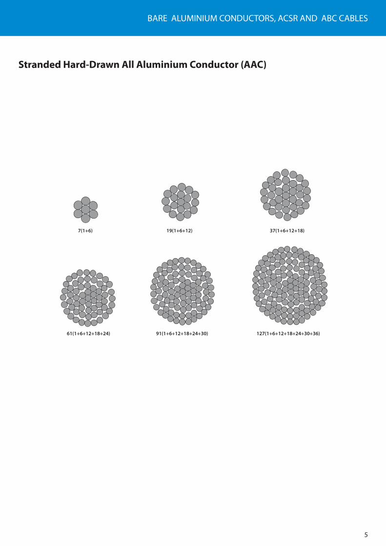
BARE ALUMINIUM CONDUCTORS, ACSR AND ABC CABLES
5
7(1+6)
61(1+6+12+18+24) 91(1+6+12+18+24+30) 127(1+6+12+18+24+30+36)
19(1+6+12) 37(1+6+12+18)
Stranded Hard-Drawn All Aluminium Conductor (AAC)

FEC Cables (M) Sdn. Bhd.
SPECIFICATION
6
AAC BS 215 Part 1
Stranded Hard-Drawn All Aluminium Conductor
Code NameNominal Area
ConstructionNo. /Wire Diameter
Calculated AreaApprox. Overall
DiameterApprox. Weight
Calculated Min. Breaking Load
DC Resistance at 20°C
mm2 No. /mm mm2 mm kg/km kN ohm/km
Midge 22 7/2.06 23.33 6.18 64 3.99 1.227
Ant 50 7/3.10 52.83 9.30 145 8.28 0.5419
Fly 60 7/3.40 63.55 10.20 174 9.90 0.4505
Wasp 100 7/4.39 106.0 13.17 290 16.00 0.2702
Hornet 150 19/3.25 157.6 16.25 434 24.70 0.1825
Chafer 200 19/3.78 213.2 18.90 587 32.40 0.1349
Cockroach 250 19/4.22 265.7 21.10 731 40.40 0.1083
Butterfly 300 19/4.65 322.7 23.25 888 48.75 0.08916
Centipede 400 37/3.78 415.20 26.46 1145 63.10 0.06944

BARE ALUMINIUM CONDUCTORS, ACSR AND ABC CABLES
Stranded Hard-Drawn All Aluminium Conductor
SPECIFICATION
7
Code nameNominal
areaConstruction
No./Wire diameterCalculated area
Approx. overalldiameter
Approx. weightCalculated
min. breakingload
DCresistance
at 20ºC
mm² No./mm mm² mm kg/km kN ohm/km
Gnat - 7/2.21 26.90 6.63 73 4.83 1.0643
Mosquito - 7/2.59 36.90 7.77 101 6.27 0.7749
Ladybird - 7/2.79 42.80 8.37 117 7.28 0.6678
Bluebottle ;- 7/3.66 73.60 10.98 201 11.78 0.3880
Earwig - 7/3.78 78.60 11.34 215 12.57 0.3638
Grasshopper - 7/3.91 84.10 11.73 230 13.46 0.3400
Clegg - 7/4.17 95.60 12.51 261 15.30 0.2989
Beetle - 19/2.67 106.4 13.35 292 18.08 0.2701
Bee - 7/4.90 132.0 14.70 361 21.12 0.2165
Caterpillar - 19/3.53 185.9 17.65 511 29.75 0.1546
Spider - 19/3.99 237.6 19.95 653 38.01 0.1210
Moth ;- 19/5.00 373.1 25.00 1025 59.69 0.0770
Drone - 37/3.58 372.4 25.06 1027 59.59 0.0774
Maybug - 37/4.09 486.1 28.63 1340 77.78 0.593
Scorpion - 37/4.27 529.8 29.89 1461 84.77 0.0544
Cicada - 37/4.65 628.3 32.55 1732 100.54 0.0459
BS EN 50182AAC

FEC Cables (M) Sdn. Bhd.
SPECIFICATION
Stranded Hard-Drawn All Aluminium Conductor
8
AAC ASTM B 231
Code nameTotal area
ConstructionNo./Wire diameter
Approx.overall diameter
Approx. weightCalculated
min. breakingload
DCresistance
at 20ºC
AWG or MCM mm² No./mm mm kg/km kN ohm/km
Peachbell 6.0 13.30 7/1.56 4.68 37 2.53 2.169
Rose 4.0 21.10 7/1.96 5.88 58 3.91 1.362
Iris 2.0 33.60 7/2.47 7.41 93 5.99 0.8574
Pansy 1.0 42.40 7/2.78 8.34 117 7.30 0.6801
Poppy 1/0.0 53.50 7/3.12 9.36 147 8.84 0.5390
Aster 2/0.0 67.40 7/3.50 10.50 186 11.10 0.4276
Phlox 3/0.0 85.00 7/3.93 11.79 234 13.50 0.3390
Oxlip 4/0.0 107.2 7/4.42 13.26 295 17.00 0.2688
Valerian 250.0 126.7 19/2.91 14.55 349 20.70 0.2275
Sneezewort 250.0 126.7 7/4.80 14.40 349 20.10 0.2275
Laurel 266.8 135.2 19/3.01 15.05 372 22.10 0.2133
Daisy 266.8 135.2 7/4.96 14.88 372 21.40 0.2133
Peony 300.0 152.0 19/3.19 15.95 418 24.30 0.1896
Tulip 336.4 170.5 19/3.38 16.90 470 27.30 0.1695
Daffodil 350.0 177.3 19/3.45 17.25 488 28.40 0.1625
Canna 397.5 201.4 19/3.67 18.35 555 31.60 0.1432
Goldentuft 450.0 228.0 19/3.91 19.55 628 35.00 0.1264
Syringa 477.0 242.0 37/2.88 20.16 665 38.60 0.1193
Cosmos 477.0 242.0 19/4.02 20.10 665 37.00 0.1193
Hyacinth 500.0 253.3 37/2.95 20.65 697 40.50 0.1137
Zinna 500.0 253.3 19/4.12 20.60 697 38.90 0.1137
Dahlia 556.5 282.0 19/4.35 21.75 776 43.30 0.1023
Mistletoe 556.5 282.0 37/3.12 21.84 776 44.30 0.1023
Meadowsweet 600.0 304.0 37/3.23 22.61 836 47.50 0.0948
Orchid 636.0 323.3 37/3.33 23.31 887 50.40 0.0893
Heuchera 650.0 329.4 37/3.37 23.59 907 51.70 0.0875

BARE ALUMINIUM CONDUCTORS, ACSR AND ABC CABLES
Stranded Hard-Drawn All Aluminium Conductor
SPECIFICATION
9
AAC ASTM B 231
Code nameTotal area
ConstructionNo./Wire diameter
Approx.overall diameter
Approx. weightCalculated
min. breakingload
DCresistance
at 20ºC
AWG or MCM mm² No./mm mm kg/km kN ohm/km
Flag 700.0 354.7 61/2.72 24.48 976 57.10 0.0813
Verbena 700.0 354.7 37/3.49 24.43 976 55.40 0.0813
Nasturtium 715.5 362.60 61/2.75 24.75 999 58.40 0.0795
Violet 715.5 362.60 37/3.53 24.71 999 56.70 0.0795
Cattail 750.0 380.0 61/2.82 25.38 1046 60.30 0.0759
Petunia 750.0 380.0 37/3.62 25.34 1046 58.60 0.0759
Lilac 795.0 402.8 61/2.90 26.10 1110 63.80 0.0715
Arbutus 795.0 402.8 37/3.72 26.04 1109 61.80 0.0715
Snapdragon 900.0 456.0 61/3.09 27.81 1256 70.80 0.0632
Coskscomb 900.0 456.0 37/3.96 27.72 1256 68.40 0.0632
Goldenrod 954.0 483.4 61/3.18 28.62 1331 75.00 0.0596
Magnolia 954.0 483.4 37/4.08 28.56 1331 72.60 0.0596
Camellia 1000.0 506.7 61/3.25 29.25 1394 78.30 0.0569
Hawkweed 1000.0 506.7 37/4.18 29.26 1395 76.20 0.0569
Larkspur 1033.5 523.7 61/3.31 29.79 1442 81.30 0.0550
Bluebell 1033.5 523.7 37/4.25 29.75 1441 78.80 0.0550
Marigold 1113.0 564.0 61/3.43 30.87 1553 87.30 0.0511
Hawthorn 1192.5 604.2 61/3.55 31.95 1662 93.50 0.0447
Narcissus 1272.0 644.5 61/3.67 33.03 1774 98.10 0.0447
Columbine 1351.0 694.8 61/3.78 34.02 1884 104.00 0.0421
Carnation 1431.0 725.1 61/3.89 35.01 1997 108.00 0.0398
Gladiolus 1510.5 765.4 61/4.00 36.00 2108 114.00 0.0376
Coreopsis 1590.0 805.7 61/4.10 36.90 2216 120.00 0.0358
Jessamine 1750.0 886.7 61/4.30 38.70 2442 132.00 0.0325
Cowslip 2000.0 1013.0 91/3.77 41.47 2787 153.00 0.0284
Lupine 2500.0 1267.0 91/4.21 46.31 3519 186.00 0.0230
Trillium 3000.0 1520.0 127/3.90 50.70 4226 223.00 0.0191
Bluebonnet 3500.0 1773.0 127/4.22 54.86 4977 261.00 0.0166

FEC Cables (M) Sdn. Bhd.
10
Bare Stranded All Aluminium Alloy Conductors (AAAC)
7(1+6)
61(1+6+12+18+24)
19(1+6+12)
37(1+6+12+18)

BARE ALUMINIUM CONDUCTORS, ACSR AND ABC CABLES
SPECIFICATION
11
AAAC BS EN 50182
Bare Stranded All Aluminium Alloy Conductor
Code nameConstruction
No./Wire diameter Calculated
area
Approx.overall
diameter
Approx.weight
Calculated min. breaking
load
DCresistance
at 20ºC
No./mm mm² mm kg/km kN ohm/km
Box 7/1.85 18.8 5.55 51 5.55 1.7480
Acacia 7/2.08 23.9 6.24 65 7.02 1.3828
Almond 7/2.34 30.1 7.02 82 8.88 1.0926
Cedar 7/2.54 35.5 7.62 97 10.46 0.9273
Deodar 7/2.77 42.2 8.31 115 12.44 0.7797
Fir 7/2.95 47.8 8.85 131 14.11 0.6875
Hazel 7/3.30 59.9 9.90 163 17.66 0.5494
Pine 7/3.61 71.60 10.80 196 21.14 0.4591
Holly 7/3.91 84.1 11.70 230 24.79 0.3913
Willow 7/4.04 89.7 12.10 245 26.47 0.3665
Oak 7/4.65 118.9 13.95 325 35.07 0.2767
Mulbery 19/3.18 150.9 15.90 414 44.52 0.2192
Ash 19/3.48 180.7 17.40 496 53.31 0.1830
Elm 19/3.76 211.0 18.80 579 62.24 0.1568
Poplar 37/2.87 239.4 20.10 659 70.61 0.1387
Sycamore 37/3.23 303.2 22.60 835 89.40 0.1095
Upas 37/3.53 362.1 24.70 998 106.82 0.0917
Yew 37/4.06 479.0 28.40 1320 141.31 0.0693
Totara 37/4.14 498.1 29.42 1372 146.93 0.0666
Rubus 61/3.50 586.9 31.50 1622 173.13 0.0567
Sorbus 61/3.71 659.4 33.40 1823 194.53 0.0505
Araucaria 61/4.14 821.1 37.30 2270 242.24 0.0406

FEC Cables (M) Sdn. Bhd.
SPECIFICATION
12
AAAC ASTM B 399
Total areConstruction
No./Wire diameterApprox.
overall diameterApprox. weight
Calculated min. breaking
load
DCresistance
at 20ºC
AWG or MCM* mm² No./mm mm kg/km kN ohm/km
6 13.3 7/1.55 4.65 36 4.22 2.519
4 21.1 7/1.96 5.88 58 6.72 1.584
2 33.6 7/2.47 7.41 92 10.70 0.9958
0 53.5 7/3.12 9.36 147 17.00 0.6261
2/0 67.4 7/3.50 10.50 185 20.50 0.4968
3/0 85.0 7/3.93 11.79 233 25.90 0.3939
4/0 107.2 7/4.42 13.26 299 32.70 0.3124
250 126.70 19/2.91 14.55 347 39.00 0.2643
300 152.0 19/3.19 15.95 417 46.80 0.2204
350 177.3 19/3.45 17.25 486 52.30 0.1889
400 202.7 19/3.69 18.45 555 59.80 0.1655
450 228.0 19/3.91 19.55 624.4 67.30 0.1469
500 253.4 19/4.12 20.60 697 74.70 0.1322
550 278.7 37/3.10 21.70 763 83.90 0.1202
600 304.0 37/3.23 22.61 832 91.50 0.1101
650 329.4 37/3.37 23.59 901.3 95.00 0.1017
700 354.7 37/3.49 24.43 971 102.00 0.09439
750 380.0 37/3.62 25.34 1041 110.00 0.08816
800 405.4 37/3.73 26.11 1109 117.00 0.0826
900 456.0 37/3.96 27.72 1249 132.00 0.07341
1000 506.7 37/4.18 29.26 1388 146.00 0.06609
* Circular mils x 1000
Bare Stranded All Aluminium Conductor

BARE ALUMINIUM CONDUCTORS, ACSR AND ABC CABLES
13
Aluminium Conductor Steel Reinforced (ACSR)
6+1
18(6+12)+1 24(9+15)+7(1+6) 26(10+16)+7(1+6) 30(12+18)+7(1+6)
6+7(1+6) 12 + 7(1+6) 14 + 7(1+6) 14 + 19(1+6+12)
54(12+18+24)+19(1+6+12)
45(9+15+21)+7(1+6) 48(10+16+22)+7(1+6) 54(12+18+24)+7(1+6) 30(12+18)+19(1+6+12)

FEC Cables (M) Sdn. Bhd.
SPECIFICATION
1�
ACSR BS 215 : PART 2
Aluminium Conductor Steel Reinforced
Code name
Nominalaluminium
areamm²
ConstructionNo./Wire diameter
Cross-sectional area Approx.overall
diameter
Approx.weight
Calculated breaking
load
DCresistance
at 20ºCAluminium Steel Aluminium Steel Total
No./mm No./mm mm² mm² mm² mm kg/km kN ohm/km
Gopher 25 6/2.36 1/2.36 26.24 4.38 30.62 7.08 106 9.61 1.093
Weasel 30 6/2.59 1/2.59 31.61 5.27 36.88 7.77 128 11.45 0.9077
Ferret 40 6/3.00 1/3.00 42.41 7.07 49.48 9.00 172 15.20 0.6776
Rabbit 50 6/3.35 1/3.35 52.88 8.81 61.70 10.05 214 18.35 0.5426
Horse 70 12/2.79 7/2.79 73.37 42.80 116.2 13.95 538 61.20 0.3936
Dog 100 6/4.72 7/1.57 105.0 13.50 118.5 14.15 394 32.70 0.2733
Wolf 150 30/2.59 7/2.59 158.1 36.80 194.9 18.13 726 69.20 0.1828
Dingo 150 18/3.35 1/3.35 158.7 8.80 167.5 16.75 506 35.70 0.1815
Lynx 175 30/2.79 7/2.79 183.4 42.80 226.2 19.53 842 79.80 0.1576
Caracal 175 18/3.61 1/3.61 184.3 10.20 194.5 18.05 587 41.10 0.1563
Panther 200 30/3.00 7/3.00 212.1 49.20 261.5 21.00 974 92.25 0.1363
Jaguar 200 18/3.86 1/3.86 210.6 11.70 222.3 19.30 671 46.55 0.1367
Batang* 300 18/4.78 7/1.68 323.0 15.50 338.5 24.16 1010 69.67 0.08914
Zebra 400 54/3.18 7/3.18 428.9 55.60 484.5 28.62 1621 131.9 0.06740
* Not in BS 215 : Part 2 but in accordance to TNB’s spec.
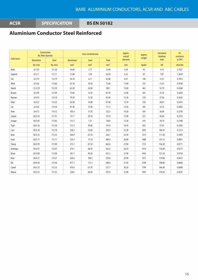
BARE ALUMINIUM CONDUCTORS, ACSR AND ABC CABLES
SPECIFICATION
15
Code name
ConstructionNo./Wire diameter
Cross-sectional area Approx.overall
diameter
Approx.weight
Calculated breaking
load
DCresistance
at 20ºCAluminium Steel Aluminium Steel Total
No./mm No./mm mm² mm² mm² mm kg/km kN ohm/km
Mole 6/1.50 1/1.50 10.60 1.77 12.40 4.50 43 4.14 2.7027
Squirrel 6/2.11 1/2.11 21.00 3.50 24.50 6.33 85 7.87 1.3659
Fox 6/2.79 1/2.79 36.70 6.11 42.80 8.37 148 13.21 0.7812
Mink 6/3.66 1/3.66 63.10 10.50 73.60 11.00 255 21.67 0.4540
Skunk 12/2.59 7/2.59 63.20 36.90 100.1 13.00 463 52.79 0.4568
Beaver 6/3.99 1/3.99 75.00 12.50 87.50 12.00 303 25.76 0.3820
Racoon 6/4.10 1/4.10 79.20 13.20 92.40 12.30 318 27.06 0.3635
Otter 6/4.22 1/4.22 83.90 14.00 97.90 12.70 339 28.81 0.3415
Cat 6/4.50 1/4.50 95.40 15.90 111.3 13.50 385 32.76 0.3003
Hare 6/4.72 1/4.72 105.0 17.50 122.5 14.20 424 36.04 0.2730
Coyote 26/2.54 7/1.91 131.7 20.10 151.8 15.90 521 45.86 0.2192
Cougar 18/3.05 1/3.05 131.5 7.31 138.8 15.30 419 29.74 0.2188
Tiger 30/2.36 7/2.36 131.2 30.60 161.8 16.50 602 57.87 0.2202
Lion 30/3.18 7/3.18 238.3 55.60 293.9 22.30 1093 100.47 0.1213
Bear 30/3.35 7/3.35 264.4 61.70 326.1 23.50 1213 111.50 0.1093
Goat 30/3.71 7/3.71 324.3 75.70 400.0 26.00 1488 135.13 0.0891
Sheep 30/3.99 7/3.99 375.1 87.50 462.6 27.90 1721 156.30 0.0771
Antelope 54/2.97 7/2.97 374.1 48.50 422.6 26.70 1414 118.88 0.0773
Bison 54/3.00 7/3.00 381.7 49.50 431.2 27.00 1443 121.30 0.0758
Deer 30/4.27 7/4.27 429.6 100.2 529.8 29.90 1971 179.00 0.0673
Elk 30/4.50 7/4.50 477.1 111.3 588.4 31.50 2190 198.80 0.0606
Camel 54/3.35 7/3.35 476.0 61.70 537.7 30.20 1799 146.40 0.0608
Moose 54/3.53 7/3.53 528.5 68.50 597.0 31.80 1997 159.92 0.0547
ACSR BS EN 50182
Aluminium Conductor Steel Reinforced

FEC Cables (M) Sdn. Bhd.
SPECIFICATION
16
ACSR ASTM B 232
Aluminium Conductor Steel Reinforced
Code name
ConstructionNo./Wire diameter
Cross-sectional area Approx.overall
diameter
Approx.weight
Calculated breaking
load
DCresistance
at 20ºCAluminium Steel Aluminium Steel Total
No./mm No./mm mm² mm² mm² mm kg/km kN ohm/km
Turkey 6/1.68 1/1.68 13.29 2.21 15.50 5.04 54 5.20 2.157
Swan 6/2.12 1/2.12 21.18 3.53 24.71 6.36 85 8.30 1.356
Swanate 7/1.96 1/2.61 21.12 5.35 26.47 6.53 100 10.50 1.356
Sparrow 6/2.67 1/2.67 33.59 5.60 39.19 8.01 136 12.70 0.8530
Sparate 7/2.47 1/3.30 33.54 8.55 42.09 8.24 159 16.10 0.8530
Robin 6/3.00 1/3.00 42.41 7.07 49.48 9.00 171 15.80 0.6765
Raven 6/3.37 1/3.37 53.52 8.92 62.44 10.11 216 19.40 0.5364
Quail 6/3.78 1/3.78 67.33 11.22 78.55 11.34 272 23.60 0.4255
Pigeon 6/4.25 1/4.25 85.12 14.19 99.30 12.75 343 29.50 0.3373
Penguin 6/4.77 1/4.77 107.2 17.87 125.1 14.31 433 37.10 0.2676
Waxwing 18/3.09 1/3.09 135.0 7.50 142.5 15.45 430 30.60 0.2133
Partridge 26/2.57 7/2.00 134.9 22.00 156.9 16.28 546 50.30 0.2142
Ostrich 26/2.73 7/2.12 152.2 24.71 176.9 17.28 613 56.50 0.1906
Linnet 26/2.89 7/2.25 170.6 27.83 198.4 18.31 688 62.70 0.1699
Oriole 30/2.69 7/2.69 170.5 39.80 210.3 18.83 783 77.00 0.1704
Chickdee 18/3.77 1/3.77 200.9 11.16 212.1 18.85 641 44.20 0.1432
Brant 24/3.27 7/2.18 201.6 26.13 227.7 19.61 761 64.90 0.1438
Iblis 26/3.14 7/2.44 201.3 32.73 234.1 19.88 812 72.50 0.1438
Lark 30/2.92 7/2.92 200.9 46.88 247.8 20.44 925 90.30 0.1442
Pelican 18/4.14 1/4.14 242.3 13.46 255.8 20.70 770 52.50 0.1193
Flicker 24/3.58 7/2.39 241.6 31.4 273.0 21.49 914 76.10 0.1199
Hawk 26/3.44 7/2.68 241.7 39.49 281.1 21.80 975 86.70 0.1199
Hen 30/3.20 7/3.20 241.3 56.30 297.6 22.40 1110 105.9 0.1202
Osprey 18/4.47 1/4.47 282.5 15.69 298.2 22.35 898 60.9 0.1022
Parakeet 24/3.87 7/2.58 282.3 36.60 318.9 23.22 1066 88.1 0.1028
Dove 26/3.72 7/2.89 282.6 45.92 328.5 23.55 1139 100.5 0.1028
Eagle 30/3.46 7/3.46 282.0 65.82 347.9 24.21 1296 123.7 0.1030
Peacock 24/4.03 7/2.69 306.1 39.78 345.9 24.20 1159 95.6 0.09449
Squab 26/3.87 7/3.01 305.8 49.81 355.6 24.51 1237 106.8 0.09449

BARE ALUMINIUM CONDUCTORS, ACSR AND ABC CABLES
SPECIFICATION
17
Aluminium Conductor Steel Reinforced
ACSR ASTM B 232
Code name
ConstructionNo./Wire diameter
Cross-sectional area Approx.overall
diameter
Approx.weight
Calculated breaking
load
DCresistance
at 20ºCAluminium Steel Aluminium Steel Total
No./mm No./mm mm² mm² mm² mm kg/km kN ohm/km
Wood Duc 30/3.61 7/3.61 307.1 71.65 378.7 25.25 1408 128.5 0.09473
Teal 30/3.61 19/2.16 307.1 69.62 376.7 25.24 1397 133.4 0.09475
Kingbird 18/4.78 1/4.78 323.0 17.95 341.0 23.88 1027 69.4 0.8942
Rook 24/4.14 7/2.76 323.1 41.88 365.0 24.84 1218 101.0 0.08989
Grosbeak 26/3.97 7/3.09 321.8 52.49 374.3 25.15 1301 112.1 0.08989
Scoter 30/3.70 7/3.70 322.6 75.26 397.8 25.88 1481 134.8 0.09011
Egret 30/3.70 19/2.22 322.6 73.50 396.1 25.90 1469 140.1 0.09012
Flamingo 24/4.23 7/2.82 337.3 43.72 381.0 25.40 1277 105.4 0.08576
Gannet 26/4.07 7/3.16 338.3 54.90 393.2 28.30 1363 117.4 0.08576
Stilt 24/4.39 7/2.92 363.3 46.88 410.2 26.31 1370 113.4 0.07989
Starling 26/4.21 7/3.28 361.9 59.15 421.1 26.68 1464 126.3 0.07992
Redwing 30/3.92 19/2.35 362.1 82.41 444.5 27.43 1651 153.9 0.08009
Tern 45/3.38 7/2.25 403.8 27.83 431.6 27.03 1332 98.3 0.07192
Condor 54/3.08 7/3.08 402.3 52.15 454.5 27.72 1521 125.4 0.07192
Cuckoo 24/4.62 7/3.08 402.3 52.15 454.5 27.74 1522 124.1 0.07190
Drake 26/4.44 7/3.45 402.6 65.44 468.0 28.11 1626 140.1 0.07192
Mallard 30/4.14 19/2.48 403.8 91.78 495.6 28.96 1836 170.8 0.07208
Ruddy 45/3.59 7/2.40 455.5 31.67 487.2 28.73 1507 108.3 0.06356
Canary 54/3.28 7/3.28 456.3 59.15 515.4 29.52 1723 141.9 0.06352
Rail 45/3.70 7/2.47 483.8 33.54 517.4 29.61 1598 115.2 0.05994
Cardinal 54/3.38 7/3.38 484.5 62.81 547.3 30.42 1826 150.3 0.05994
Ortolan 45/3.85 7/2.57 523.9 36.31 560.2 30.81 1731 123.2 0.05531
Curlew 54/3.52 7/3.52 525.5 68.12 593.6 31.68 1978 162.8 0.05531
Bluejay 45/4.00 7/2.66 565.5 38.90 604.4 31.98 1866 132.6 0.05161
Finch 54/3.65 19/2.19 565.0 71.57 636.6 32.85 2128 173.9 0.05161
Bunting 45/4.14 7/2.76 605.8 41.88 647.6 33.12 1997 141.9 0.04820
Grackle 54/3.77 19/2.27 602.8 76.89 679.7 33.97 2278 185.9 0.04820
Bittern 45/4.27 7/2.85 644.4 44.66 689.1 34.17 2131 151.7 0.04518

FEC Cables (M) Sdn. Bhd.
SPECIFICATION
18
Aluminium Conductor Steel Reinforced
ASTM B 232ACSR
Code name
ConstructionNo./Wire diameter
Cross-sectional area Approx.overall
diameter
Approx.weight
Calculated breaking
load
DCresistance
at 20ºCAluminium Steel Aluminium Steel Total
No./mm No./mm mm² mm² mm² mm kg/km kN ohm/km
Pheasant 54/3.90 19/2.34 645.1 81.71 726.8 35.10 2431 193.9 0.04518
Dipper 45/4.40 7/2.92 684.2 46.88 731.1 35.16 2263 161.0 0.04259
Martin 54/4.02 19/2.41 685.4 86.67 772.1 36.17 2582 205.9 0.04259
Bobolink 45/4.53 7/3.02 725.3 50.14 775.4 36.24 2397 170.8 0.04016
Plover 54/4.14 19/2.48 726.90 91.78 818.70 37.24 2735 218.0 0.04016
Nuthatch 45/4.65 7/3.10 764.2 52.83 817.0 37.20 2530 178.4 0.03802
Parrot 54/4.25 19/2.55 766.1 97.0 863.1 38.25 2884 230.4 0.03802
Lapwing 45/4.77 7/3.18 804.2 55.60 859.8 38.16 2664 187.3 0.03612
Falcon 54/4.36 19/2.62 806.2 102.4 908.7 39.26 3039 242.9 0.03612

BARE ALUMINIUM CONDUCTORS, ACSR AND ABC CABLES
19
ABC
Low Voltage Aerial Cable
Cable Size1 x 16
+ 1 x 253 x 16
+ 1 x 253 x 95
+ 1 x 70+ 1 x 16
3 x 185+ 1 x 120+ 1 x 16
Phase Conductor
Conductor
Cross-sectional area mm² 16 16 95 185
Number of wires 7 7 19 37
Number of cores 1 3 3 3
Nom. insulation thickness mm 1.00 1.00 1.60 2.00
Approx. diameter of insulated core mm 6.9 6.9 15.0 20.4
Max. DC resistance of conductor at 20ºC Ω/km 1.91 1.91 0.320 0.164
Messenger/Neutral Conductor
Conductor
Cross-sectional area mm² 25 25 70 120
Number of wires 7 7 19 19
Number of cores 1 1 1 1
Nom. insulation thickness mm 1.20 1.20 1.40 1.60
Approx. diameter of insulated core mm 8.6 8.6 13.0 16.6
Max. DC resistance of conductor at 20ºC Ω/km 1.312 1.312 0.469 0.273
Calculated Breaking Load kN 7.5 7.5 36.0 36.0
Lighting Conductor
Conductor
Cross-sectional area mm² * * 16 16
Number of wires * * 7 7
Number of cores * * 1 1
Nom. insulation thickness mm * * 1.0 1.0
Approx. diameter of insulated core mm * * 6.9 6.9
Max. DC resistance of conductor at 20ºC Ω/km * * 1.91 1.91
Approx. overall diameter of cable mm 15.5 19.2 40.5 49.3
Approx. overall weight of the cable kg/km 160 290 1300 2360
Cable length per drum m 1000 1000 500 500
Phase Conductor
Insulation
Neutral Conductor (Messenger)
Street Lighting

FEC Cables (M) Sdn. Bhd.
20
Medium Voltage Aerial Cable
Cable Size3 x 70
+ 1 x 503 x 150
+ 1 x 503 x 240
+ 1 x 50
Phase Conductor
Conductor
Cross-sectional area mm² 70 120 240
Number of wires 19 37 37
Number of cores 3 3 3
Min. thickness of conductor screen mm 0.50 0.50 0.50
Nom. insulation thickness mm 3.40 3.40 3.40
Min. thickness of insulation screen mm 0.50 0.50 0.50
Nominal thickness of metallic screen mm 0.105 0.105 0.105
Min. thickness of outer sheath mm 2.30 2.30 2.30
Approx. overall diameter of cable mm 25.9 30.7 34.6
Messenger/Neutral Conductor
Cross-sectional area mm² 50 50 50
Number of wires 7 7 7
Number of cores 1 1 1
Calculated Breaking Load kN 63.0 63.0 63.0
Standard Cable
Approx. overall diameter of stranded cable mm 60.6 70.9 79.3
Approx. net weight kg/km 3000 4170 5320
Max. DC resistance of conductor at 20ºC Ω/km 0.443 0.206 0.125
Cable length per drum m 500 500 500
Conductor
Conductor Screen
Insulation
Insulation Screen
Metallic Screen
Binder Tape
Outer Sheath
Messenger
ABC TNBD & IEC 60502-211 kV SPECIFICATION

BARE ALUMINIUM CONDUCTORS, ACSR AND ABC CABLES
21
TNBD & IEC 60502-233 kV SPECIFICATION
Cable Size3 x 70
+ 1 x 503 x 150
+ 1 x 50
Phase Conductor
Conductor
Cross-sectional area mm² 70 150
Number of wires 19 37
Number of cores 3 3
Min. thickness of conductor screen mm 0.50 0.50
Nom. insulation thickness mm 8.00 8.00
Min. thickness of insulation screen mm 0.50 0.50
Nominal thickness of metallic screen mm 0.105 0.105
Min. thickness of outer sheath mm 2.30 2.30
Approx. overall diameter of cable mm 35.1 39.9
Messenger/Neutral Conductor
Cross-sectional area mm² 50 50
Number of wires 7 7
Number of cores 1 1
Calculated Breaking Load kN 63.0 63.0
Standard Cable
Approx. overall diameter of stranded cable mm 80.4 90.8
Approx. net weight kg/km 4530 5880
Max. DC resistance of conductor at 20ºC Ω/km 0.443 0.206
Cable length per drum m 500 500
Conductor
Conductor Screen
Insulation
Insulation Screen
Metallic Screen
Binder Tape
Outer Sheath
Messenger
ABC
Medium Voltage Aerial Cable

FEC Cables (M) Sdn. Bhd.
22

Factory 1Persiaran Raja Muda, �0000 Shah Alam, Selangor Darul Ehsan, Malaysia.(P.O. Box 7006, �0700 Shah Alam)Tel : 6 03 - 5519 1110 (Hotline) Fax : 6 03 - 5519 1296
Factory 2No. 16, Jalan Keluli 2, Bukit Raja Industrial Area, �1050 Klang, Selangor Darul Ehsan, Malaysia. Tel : 6 03 - 33�3 5837 (Hotline) Fax : 6 03 - 33�3 58�3
Sales OfficePersiaran Raja Muda, �0000 Shah Alam, Selangor Darul Ehsan, MalaysiaTel : 6 03 - 5519 1110 (Hotline) Fax : 6 03 - 5519 1296 / 5513 8688Email : [email protected]
www.fec.com.my
FEC Cables (M) Sdn. Bhd.(7293-W)
Des
ign
by
Tel :
03
- 772
2 48
18