Introduction - Nettsiden er flyttet - Institutt for ... · Introduction III Introduction The LD302...
52
L D3 0 2 ME
Transcript of Introduction - Nettsiden er flyttet - Institutt for ... · Introduction III Introduction The LD302...

L D 3 0 2 M E

web: www.smar.com
smar Specifications and information are subject to change without notice.
For the latest updates, please visit the SMAR website above.
BRAZIL Smar Equipamentos Ind. Ltda. Rua Dr. Antonio Furlan Jr., 1028 Sertãozinho SP 14170-480 Tel.: +55 16 3946-3510 Fax: +55 16 3946-3554 e-mail: [email protected]
ARGENTINA Smar Argentina Soldado de La Independencia, 1259 (1429) Capital Federal – Argentina Telefax: 00 (5411) 4776 -1300 / 3131 e-mail: [email protected]
CHINA Smar China Corp. 3 Baishiqiao Road, Suite 30233 Beijing 100873, P.R.C. Tel.: +86 10 6849-8643 Fax: +86-10-6894-0898 e-mail: [email protected]
FRANCE Smar France S. A. R. L. 42, rue du Pavé des Gardes F-92370 Chaville Tel.: +33 1 41 15-0220 Fax: +33 1 41 15-0219 e-mail: [email protected]
GERMANY Smar GmbH Rheingaustrasse 9 55545 Bad Kreuznach Germany Tel: + 49 671-794680 Fax: + 49 671-7946829 e-mail: [email protected]
MEXICO Smar México Cerro de las Campanas #3 desp 119 Col. San Andrés Atenco Tlalnepantla Edo. Del Méx - C.P. 54040 Tel.: +53 78 46 00 al 02 Fax: +53 78 46 03 e-mail: [email protected]
SINGAPORE Smar Singapore Pte. Ltd. 315 Outram Road #06-07, Tan Boon Liat Building Singapore 169074 Tel.: +65 6324-0182 Fax: +65 6324-0183 e-mail: [email protected]
USA Smar International Corporation 6001 Stonington Street, Suite 100 Houston, TX 77040 Tel.: +1 713 849-2021 Fax: +1 713 849-2022 e-mail: [email protected]
Smar Laboratories Corporation 10960 Millridge North, Suite 107 Houston, TX 77070 Tel.: +1 281 807-1501 Fax: +1 281 807-1506 e-mail: [email protected]
Smar Research Corporation 4250 Veterans Memorial Hwy. Suite 156 Holbrook , NY 11741 Tel: +1-631-737-3111 Fax: +1-631-737-3892 e-mail: [email protected]
Introduction
III
Introduction The LD302 is part of first generation of Fieldbus devices. It is a transmitter for differential, absolute and gauge pressure, level and flow measurements. It is based on a field-proven capacitive sensor that provides reliable operation and high performance. The digital technology used in the LD302enables the choice of several types of transfer functions, and easy interface between the field and the control room. Also it has several interesting features that will considerably reduce the installation, operation and maintenance costs. The LD302 is part of Smar's complete 302 line of Fieldbus devices.
Fieldbus is not only a replacement for 4-20 mA or intelligent / smart transmitter protocols, it contains much more. Fieldbus is a complete system enabling distribution of the control function to equipment in the field.
Some of the advantages of bi-directional digital communications are known from existing smart transmitter protocols: Higher accuracy, multi-variable access, remote configuration and diagnostics, and the multi-dropping of several devices on a single pair of wires.
These protocols are not intended to transfer control data, but maintenance information. Therefore they are slow and too inefficient to be used.
The main requirements for Fieldbus are to overcome these problems. Closed loop control with performance like a 4-20 mA system requires higher speed. Since higher speed means higher power consumption, this clashes with the need for intrinsic safety. Therefore, a moderately high communication speed has been selected, and the system was designed to have a minimum of communication overhead. Using scheduling, the system controls variable sampling, algorithm execution, and communication so as to optimize the usage of the network, will not lose time. Thus, high closed loop performance is achieved.
Using Fieldbus technology, with its capability to interconnect several devices, very large control schemes can be constructed. In order to be user friendly, the function block concept was introduced (users of SMAR CD600 should be familiar with this, since it was implemented several years ago). The user may now easily build and overview complex control strategies. Another advantage was added: flexibility. The control strategy may be edited without having to rewire or change any hardware.
The LD302, like the rest of the 302 family, has several built-in Function Blocks, such as the PID controller, Input Selector and Splitter/Output Selector, therefore eliminating the need for a separate control device. This feature reduces communication, so there is less dead-time and tighter control, not to mention the reduction in cost.
Other function blocks are also available. They allow flexibility in control strategy implementation.
The need for implementation of Fieldbus in small as well as large systems was considered when developing the entire 302 line of Fieldbus devices. They have the common features of being able to act as a master on the network and be configured locally using a magnetic tool, eliminating the need for a configurator or console in many basic applications.
The LD302 is available as a product of its own, but also replaces the circuit board for the LD301. They both use the same sensor board. Refer to the maintenance section of this manual for instructions on upgrading. The LD302 is part of SMAR's Series 302 of Fieldbus devices.
The LD302, like its predecessor LD301, has many built-in blocks, eliminating the need for a separate control device. The communication requirement is considerably reduced, and that means less dead-time and tighter control is achieved, not to mention the reduction in cost. They allow flexibility in control strategy implementation.
Get the best results of the LD302 by carefully reading these instructions.
LD302 - Operation and Maintenance Instruction Manual
IV
NOTE
This Manual is compatible with version 3.XX, where 3 denotes software version and XX software release. The indication 3.XX means that this manual is compatible with any release of software version 3.

Index
V
Table of Contents
INSTALLATION............................................................................................................................ 1.1
GENERAL ....................................................................................................................................................................1.1 MOUNTING..................................................................................................................................................................1.1 HOUSING ROTATION.................................................................................................................................................1.5 BUS AND TREE TOPOLOGY AND NETWORK CONFIGURATION ..........................................................................1.7
OPERATION ................................................................................................................................ 2.1
FUNCTIONAL DESCRIPTION – SENSOR .................................................................................................................2.1 FUNCTIONAL DESCRIPTION – ELETRONICS..........................................................................................................2.2 THE DISPLAY..............................................................................................................................................................2.3
CONFIGURATION ....................................................................................................................... 3.1
TRANSDUCER BLOCK...............................................................................................................................................3.1 HOW TO CONFIGURE A TRANSDUCER BLOCK .....................................................................................................3.1 LOWER AND UPPER TRIM ........................................................................................................................................3.2 PRESSURE TRIM – LD302.........................................................................................................................................3.3 THROUGH LOCAL ADJUSTMENT.............................................................................................................................3.5 CHARACTERIZATION TRIM.......................................................................................................................................3.5 SENSOR INFORMATION ...........................................................................................................................................3.7 TEMPERATURE TRIM ................................................................................................................................................3.8 SENSOR DATA READING ..........................................................................................................................................3.8 TRANSDUCER DISPLAY – CONFIGURATION..........................................................................................................3.9 DISPLAY TRANDUCER BLOCK ...............................................................................................................................3.10 DEFINITION OF PARAMETERS AND VALUES .......................................................................................................3.10 PROGRAMING USING LOCAL ADJUSTMENT........................................................................................................3.13 J1 JUMPER CONNECTIONS....................................................................................................................................3.14 W1 JUMPER CONNECTIONS ..................................................................................................................................3.14
MAINTENANCE PROCEDURES ............................................................................................... 4.1
GENERAL ....................................................................................................................................................................4.1 DISASSEMBLY PROCEDURE....................................................................................................................................4.2 SENSOR CLEANING ..................................................................................................................................................4.2 ELECTRONIC CIRCUIT .............................................................................................................................................4.3 REASSEMBLY PROCEDURE.....................................................................................................................................4.3 SENSOR MOUNTING .................................................................................................................................................4.3 ELECTRONIC CIRCUIT ..............................................................................................................................................4.5 INTERCHANGEABILITY..............................................................................................................................................4.5 UPGRADING LD301 TO LD302 ..................................................................................................................................4.6 RETURNING MATERIALS ..........................................................................................................................................4.6
TECHNICAL CHARACTERISTICS ............................................................................................. 5.1
FUNCTIONAL SPECIFICATIONS ...............................................................................................................................5.1 PERFORMANCE SPECIFICATIONS ..........................................................................................................................5.2 PHYSICAL SPECIFICATIONS ....................................................................................................................................5.2 ORDERING CODE ......................................................................................................................................................5.4 CONTROL DRAWING .................................................................................................................................................5.6

LD302 - Operation and Maintenance Instruction Manual
VI
Section 1
1.1
Installation The overall accuracy of a flow, level, or pressure measurement depends on several variables. Although the transmitter has an outstanding performance, proper installation is essential to maximize its performance.
Among all factors, which may affect transmitter accuracy, environmental conditions are the most difficult to control. There are, however, ways of reducing the effects of temperature, humidity and vibration.
General
The LD302 has a built-in temperature sensor to compensate for temperature variations. At the factory, each transmitter is submitted to a temperature cycle process, and the characteristics under different pressures and temperatures are recorded in the transmitter memory. In the field, this feature minimizes the temperature variation effect.
Placing the transmitter in areas protected from extreme environmental changes can minimize temperature oscillation effects.
The transmitter should be installed a way as to avoid, as much as possible, direct exposure to the sun or any source of irradiated heat. Installation close to lines and vessels should also be avoided. Use longer sections of impulse piping between tap and transmitter whenever there is a high temperature process. The use of sunshades or heat shields to protect the transmitter from external heat sources should be considered.
Humidity is fatal for electronic circuits. In humidity exposed areas, the O-rings for the electronic housing covers must be correctly placed and the covers must be completely closed by tightening them by hand until the O-rings are compressed.
Do not use tools to close the covers. Removal of the electronics cover in the field should be reduced to the minimum necessary, as each time it is removed; the circuits are exposed to the humidity. The electronic circuit is protected by a humidity proof coating, but frequent exposure to humidity may affect the protection provided. It is also important to keep the covers tightened in place. Every time they are removed, the threads are exposed to corrosion, since painting cannot protect these parts. Code-approved sealing methods should be employed on the inlet conduit the transmitter. The unused outlet connection should be plugged accordingly.
Although the transmitter is virtually insensitive to vibration, installation close to pumps, turbines or other vibrating equipment should be avoided. Proper winterization (freeze protection) should be employed to prevent freezing within the measuring chamber, since this will result in an inoperative transmitter and could even damage the cell.
Mounting
NOTE
When installing or storing the transmitter, the diaphragm must be protected to avoid scratching-denting or perforation of its surface.
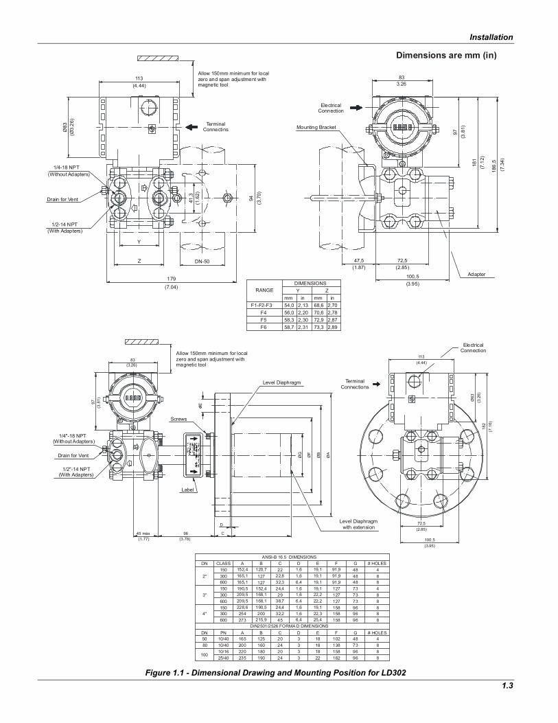
The transmitter has been designed to be heavy duty and lightweight at the same time. This makes its mounting easier; mounting positions are shown in Figure 1.1 - Dimensional Drawing and Mounting Position for LD302.
Existing standards for the manifolds have also been considered, and standard designs fit perfectly to the transmitter flanges.
If the process fluid contain solids in suspension, install valves or rod-out fittings at regular intervals to clean out the pipes.
LD302 - Operation and Maintenance Instruction Manual
1.2
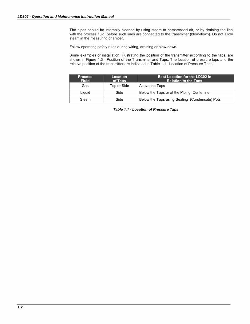
The pipes should be internally cleaned by using steam or compressed air, or by draining the line with the process fluid, before such lines are connected to the transmitter (blow-down). Do not allow steam in the measuring chamber.
Follow operating safety rules during wiring, draining or blow-down.
Some examples of installation, illustrating the position of the transmitter according to the taps, are shown in Figure 1.3 - Position of the Transmitter and Taps. The location of pressure taps and the relative position of the transmitter are indicated in Table 1.1 - Location of Pressure Taps.
Process Fluid
Locationof Taps
Best Location for the LD302 in Relation to the Taps
Gas Top or Side Above the Taps
Liquid Side Below the Taps or at the Piping Centerline
Steam Side Below the Taps using Sealing (Condensate) Pots
Table 1.1 - Location of Pressure Taps
Installation
1.3
Figure 1.1 - Dimensional Drawing and Mounting Position for LD302
(With Adapters)
2,312,302,202,13
Z
Y
DN-50
179(7.04)
inmmF1-F2-F3
F4F5F6
56,058,358,7
54,0
RANGE Y
72,5(2.85)
mm in
2,872,782,70
2,89
70,672,973,3
68,6
(1.87)
Z
47,5
100,5(3.95)
Adapter
186,
5
1/4-18 NPT
1/2-14 NPT
(Without Adapters)
Drain for Vent
Ø83
(Ø3.
26)
Mounting BracketTerminalConnectins
41,3
(1.6
2)
(3.7
0)94
Allow 150mm minimum for localzero and span adjustment with magnetic tool
113(4.44)
Electrical Connection
181
(7.1
2)
(3.8
1)97
833.26
(7.3
4)
1/2"-14 NPT(With Adapters)
45 máx(1.77)
Drain for Vent
1/4"-18 NPT(Without Adapters)
97(3
.81)
(2.85)
100,5
72,5
Level Diaphragm TerminalConnections
113(4.44)
(3.2
6)18
2(7
.16)
Ø83
ElectricalConnection
(3.95)
(3.78)96
Label
C
D
Screws
E
(3.26)83
Allow 150mm minimum for local zero and span adjustment with magnetic tool
ØG
ØF
ØA
ØB
120,7127
B # HOLES
87312738,7 6,4 22,2
1832024
2420 3
3
31822
18
1,61,6
6,445
C
24,432,2
25,4
D E
19,122,3
44810273
9696158
162
13888
8
9696
G
96158
F
158158
8
88
1,61,6
1,61,66,432,3
2924,4
22,822C
19,122,2
19,1
D19,119,1
E G
4848
48
7373
91,9127127
91,991,9
F
48
8
48
ANSI-B 16.5 DIMENSIONS
DIN2501/2526 FORMA D DIMENSIONS
600 209,5 168,1
50
100
80
DN
4"
12516510/4010/4010/1625/40
220235
200180190
160
228,6
600
PN
150300
273 215,9
A B
254190,5200
3"
2"
DN
165,1152,4
209,5190,5165,1600
300150
300150
CLASS
152,4168,1
127
A
Dimensions are mm (in)
DIMENSIONS
Level Diaphragmwith extension
# HOLES
LD302 - Operation and Maintenance Instruction Manual
1.4
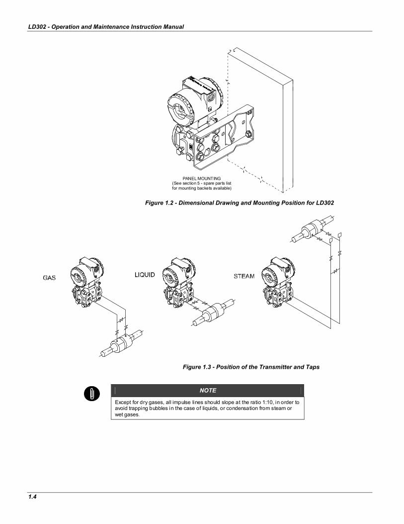
Figure 1.2 - Dimensional Drawing and Mounting Position for LD302
Figure 1.3 - Position of the Transmitter and Taps
NOTE
Except for dry gases, all impulse lines should slope at the ratio 1:10, in order to avoid trapping bubbles in the case of liquids, or condensation from steam or wet gases.
PANEL MOUNTING(See section 5 - spare parts listfor mounting backets available)
Installation
1.5
Housing Rotation The housing can be rotated in order to get the digital display in better position. To rotate it, release the Housing Rotation Set Screw. (See Figure 4.3 - For Possible Positions of the Display)
WARNING
EXPLOSION PROOF INSTALLATIONS The electronic housing and the sensor assembly in potentially explosive atmospheres must have a minimum of 6 threads fully engaged. The provided joint allows 1 extra turn. Try to adjust the display window position by rotating the housing clockwise. If the thread reaches the end before the desired position, then rotate the housing counterclockwise, but not by more than one turn of the thread end. Transmitters have a stopper that restricts housing rotation to one turn. See Figure 4.1 - Sensor Rotation Stopper.
The digital display itself can also be rotated. (See Figure 4.3 - Four Possible Positions of the Display)
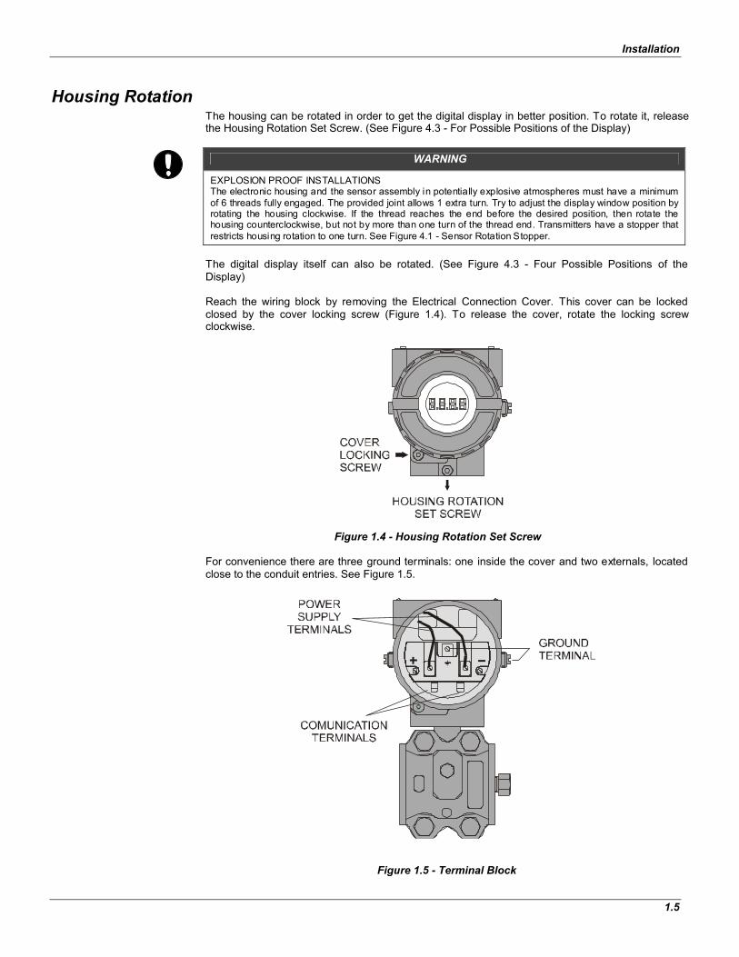
Reach the wiring block by removing the Electrical Connection Cover. This cover can be locked closed by the cover locking screw (Figure 1.4). To release the cover, rotate the locking screw clockwise.
Figure 1.4 - Housing Rotation Set Screw
For convenience there are three ground terminals: one inside the cover and two externals, located close to the conduit entries. See Figure 1.5.
Figure 1.5 - Terminal Block

LD302 - Operation and Maintenance Instruction Manual
1.6
NOTE
Please refer to the General Installation, Operation and Maintenance Manual for more details.
The Figure 1.6 - Conduit Installation Diagram, shows the correct installation of the conduit, in order to avoid penetration of water, or other substance, which may cause malfunctioning of the equipment.
Figure 1.6 - Conduit Installation Diagram.
NOTE
The transmitters are calibrated in the vertical position and a different mounting position displaces the zero point. In these conditions, it is recommended to do the zero pressure trim. The zero trim is to compensate the final assembly position and its performance, when the transmitter is in its final position. When the zero trim is executed, make sure the equalization valve is open and the wet leg levels are correct.
For the absolute pressure transmitter, the assembly effects correction should be done using the Lower trim, due to the fact that the absolute zero, is the reference for these transmitters, so there is no need for a zero value for the Lower trim.
When the sensor is in the horizontal position, the weight of the fluid pushes the diaphragm down, making it necessary a Lower Pressure Trim.
Fig. 1.7 - Sensor Positions
CORRECT
WIRES
INCORRECT
SENSOR IN THE VERTICAL POSITION SENSOR IN THE HORIZONTAL POSITION
HEAD OF THE FLUID
DIAPHRAGM SENSORDIAPHRAGM SENSOR

Installation
1.7
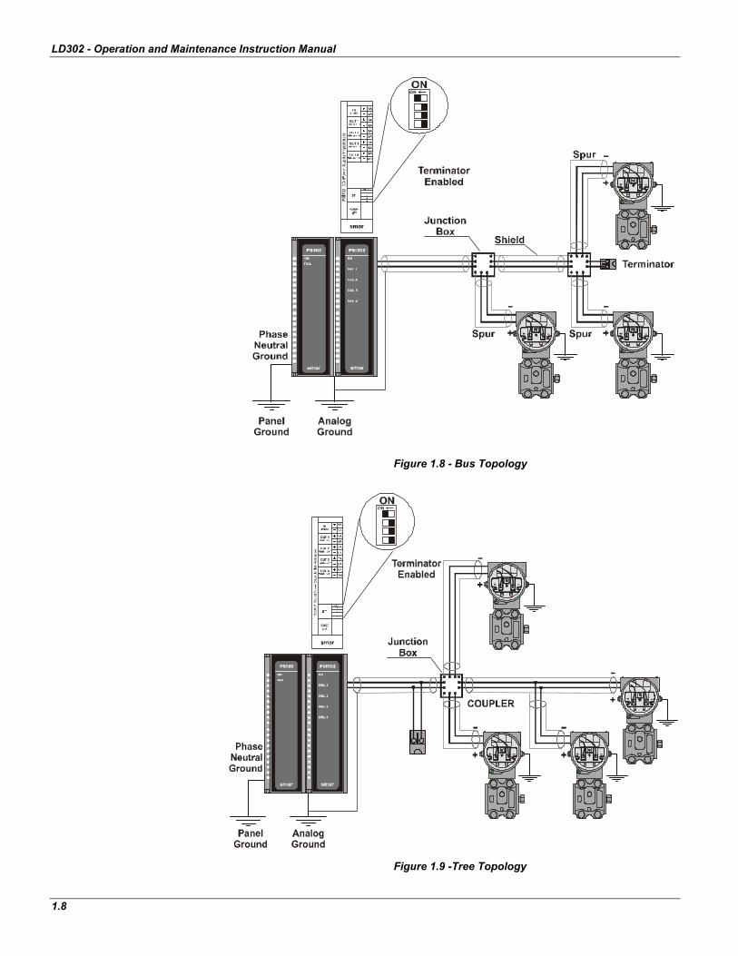
Bus and Tree Topology and Network Configuration
The LD302 uses the 31.25 kbit/s voltage mode option for the physical signaling. All other devices on the same bus must use the same signaling. All devices are connected in parallel along the same pair of wires.
Many types of Fieldbus devices may be connected on the same bus.
The LD302 is powered via the bus. The limit for such devices is 16 for one bus for non-intrinsically safe requirement.
In hazardous area, the number of devices may be limited by intrinsically safe restrictions.
The LD302 is protected against reverse polarity, and can withstand ±35 VDC without damage. However it will not work in this situation.
Connection of the LD302 working in bus topology is in Figure 1.8.
Connection of the LD302 working in tree topology is in Figure 1.9.
The connection of couplers should be kept at less than 15 per 250 m.
WARNING
In hazardous areas with explosion proof requirements, the covers must be tightened with at least 8 turns. In order to avoid moisture penetration or corrosive gases, tighten the Cover until the O'ring touches the housing. Then, tighten another 1/3 turn (120 ) to guarantee the sealing. Lock the covers using the locking screw.
In hazardous zones with intrinsically safe or non incendive requirements, the circuit entity parameters and applicable installation procedures must be observed.
Cable access to wiring connections is obtained by the two conduit outlets. Conduit threads should be sealed by means of code-approved sealing methods. The unused outlet connection should be plugged and sealed accordingly.
Should other certifications be necessary, refer to the certification or specific standard for installation limitations.
LD302 - Operation and Maintenance Instruction Manual
1.8
Figure 1.8 - Bus Topology
Figure 1.9 -Tree Topology LD2EM106.CDR

Section 2
2.1
Operation The LD302 Series Pressure Transmitters use capacitive sensors (capacitive cells) as pressure sensing elements, as shown in Figure 2.1 - Capacitive Cell. This is the same sensor that is used in the LD301 series, the sensor modules are therefore interchangeable.
Figure 2.1 - Capacitive Cell
Functional Description - Sensor
Where,P1 and P2 are the pressures and P1 P2
CH = Capacitance between the fixed plate on P1 side and the sensing diaphragm. CL = Capacitance between the fixed plate on the P2 side and the sensing diaphragm. d = Distance between CH and CL fixed plates.
d = Sensing diaphragm's deflection due to the differential pressure P = P1 - P2.
Knowing that the capacitance of a capacitor with flat, parallel plates may be expressed as a function of plate area (A) and distance (d) between the plates:
Where, = Dielectric constant of the medium between the capacitor's plates.
The CH and CL should be considered as capacitances of flat and parallel plates with identical areas,
however, should the differential pressure ( P) applied to the capacitive cell not deflect the sensing
diaphragm beyond d/4, it is possible to assume P as proportional to d, that is:
By developing the expression (CL - CH)/(CL + CH), it follows that:
dAC
CLdd
Add
ACH)2(
and)2(
dP

LD302 - Operation and Maintenance Instruction Manual
2.2
Though distance (d) between the fixed plates CH and CL is constant. It is possible to conclude that the expression (CL - CH)/(CL + CH) is proportional to d and therefore, to the differential pressure to be measured. Thus, it is possible to conclude that the capacitive cell is a pressure sensor formed by two capacitors whose capacitances vary according to the applied differential pressure.
Functional Description – Electronics
Refer to the block diagram Figure 2.2 - LD302 Block Diagram Hardware. The function of each block is described below.
Figure 2.2 - LD302 Block Diagram Hardware
OscillatorThis oscillator generates a frequency as a function of sensor capacitance.
Signal Isolator The control signals from the CPU and the signal from the oscillator are isolated to avoid ground loops.
Central Processing Unit (CPU), RAM, FLASH and EEPROM The CPU is the intelligent portion of the transmitter; it is responsible for the management and operation of measurement, block execution, self-diagnostics and communication. The program is stored in a FLASH memory for easy upgrade and saves the data in case of a power down. For temporary storage of data there is a RAM. The data in the RAM is lost if the power is switched off, however the main board has a nonvolatile EEPROM memory where the static data configured that must be retained is stored. Examples of such data are the following: calibration, links and identification data.
Sensor EEPROM Another EEPROM is located within the sensor assembly. It contains data pertaining to the sensor's characteristics at different pressures and temperatures. This characterization is done for each sensor at the factory. It also contains the factory settings; they are useful in case of main board replacement, when its does an automatic upload of data from the sensor board to main board.
dd
CHCLCHCL 2
Operation
2.3
Fieldbus Modem Monitors line activity, modulates and demodulates communication signals, inserts and deletes start and end delimiters, and checks integrity of frame received.
Power Supply Takes power from the loop-line to power the transmitter circuitry.
Power Isolation Isolates the signals from the input section, the power to the input section must be isolated.
Display Controller Receives data from the CPU, identifying which segments on the liquid crystal Display to turn on. The controller drives the display background and the segment control signals.
Local Adjustment There are two switches that are magnetically activated. A magnetic tool without mechanical or electrical contact can activate them.
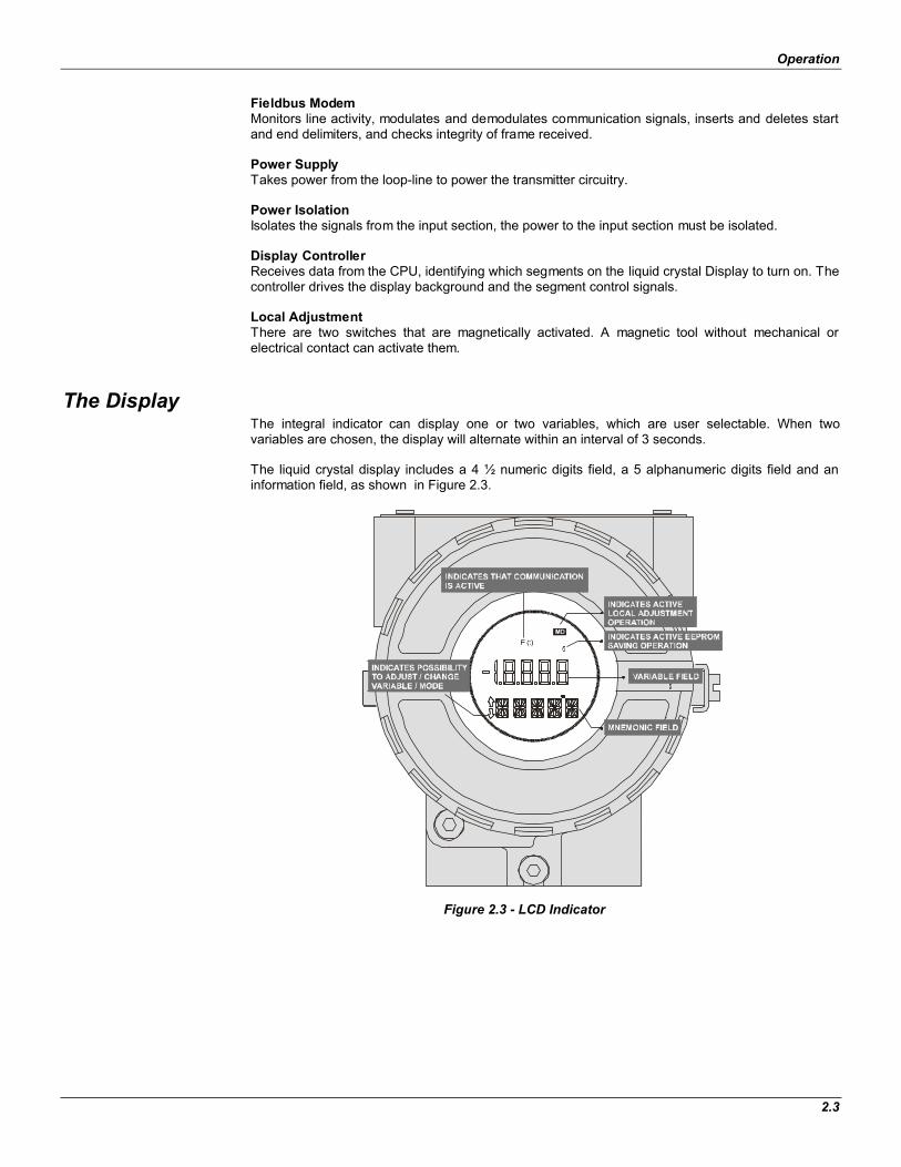
The Display The integral indicator can display one or two variables, which are user selectable. When two variables are chosen, the display will alternate within an interval of 3 seconds.
The liquid crystal display includes a 4 ½ numeric digits field, a 5 alphanumeric digits field and an information field, as shown in Figure 2.3.
Figure 2.3 - LCD Indicator

LD302 - Operation and Maintenance Instruction Manual
2.4
Section 3
3.1
Configuration One of the many advantages of Fieldbus is that device configuration does not depend on the configurator since the technology works with device descriptions and the interoperability concepts. The LD302 may be configured from a third party terminal or an operator console. A particular configurator is therefore not addressed here.
This section describes the characteristics of the blocks in the LD302. They follow the Fieldbus specifications, but as for of transducer blocks, the input transducer block and display, they have other special features.
Transducer Block
The transducer block insulates the function blocks from the specific I/O hardware, such as sensors or actuators. The transducer block controls access to the I/O through the manufacturer specific implementation. This allows the transducer block to be executed as frequently as necessary to obtain good data from sensors without burdening the function blocks that use the data. It also insulates the function block from the manufacturer specific characteristics of certain hardware.
By accessing the hardware, the transducer block can get data from the I/O or pass control data to it. The connection between a Transducer block and a Function block is called a channel. These blocks can exchange data from their interface.
Usually, the transducer blocks perform functions, such as linearization, characterization, temperature compensation, hardware control and data exchange.
How to Configure a Transducer Block
Each time a field device is selected on the SYSCON by instantiating them on the Operation menu, automatically a transducer block appears on the screen.
The icon indicates that a transducer block has been created, and by clicking twice on the icon, it can be accessed.
The transducer block has an algorithm, a set of contained parameters and a channel connecting it to a function block.
The algorithm describes the behavior of the transducer as a data transfer function between the I/O hardware and other function blocks. The set of contained parameters are unable to link to other blocks. These contained parameters define the user interface to the transducer block. They can be divided into Standard and Manufacturer Specific.
The standard parameters will be present for pressure, temperature, actuation devices, etc., regardless of the manufacturer. Oppositely, the manufacturers’ specific ones are defined by themselves for their own purposes. As common manufacturer specific parameters, there are calibration settings, material information, linearization curve, etc.
When a standard routine calibration is performed, the user conducts a step by step method. The method is generally defined as a guideline to help the user with common tasks. The SYSCON identifies each method associated with the parameters and enables the interface to it.

LD302 – Operation and Maintenance Instruction Manual
3.2
The SYSCON configuration software can configure many parameters of the Input Transducer block.
Figure 3.1 - Function and Transducer Blocks
Lower and Upper Trim
Each sensor has a characteristic curve that relates the applied pressure and the sensor signal. This curve is determined for each sensor and it is stored in a memory along with the sensor. When the sensor is connected to the transmitter circuit, the content of its memory is made available to the microprocessor.
Sometimes the value on the transmitter display and the transducer block reading may not match to the applied pressure. The reasons may be:
The transmitter mounting position. The user's pressure standard differs from the factory standard. The transmitter had its original characterization curve shifted by overpressure, over heating or by long term drift.
The TRIM is used to match the reading with the applied pressure. There are two types of trim available:
Lower Trim: It is used to trim the reading at the lower range. The operator informs the LD302 of the correct reading for the applied pressure. The most common discrepancy is the lower reading.
NOTE:
Check on section 1, the note on the influence of the mounting position on the indicator. For better accuracy, the trim adjustment should be made in the in the lower and upper values of the operation range values.
Upper Trim: It is used to trim the reading at the upper range. The operator informs the correct reading for the applied pressure.
For accuracy, trim should be done within the operating range. The Figure 3.2 - LD302 SYSCON - Transducer Configuration Screen, Figure 3.3 - LD302 SYSCON - Transducer Configuration Screen and Figure 3.4 – LD302 SYSCON - Transducer Configuration Screen below shows the trim adjustment operation into SYSCON.
As you can see the Transducer and Display are treated as special type of Function Blocks, called Transducer Blocks.
The device was instantiated as LD302
Here, you can see all blocks instantiated.

Configuration
3.3
Pressure Trim - LD302
Via SYSCON It is possible to calibrate the transmitter through the parameters CAL_POINT_LO and CAL_POINT_HI. A convenient engineering unit should be chosen before starting the calibration. This engineering unit is configured by the CAL_UNIT parameter. After its configuration the parameters related to calibration will be converted to this unit.
Figure 3.2 - LD302 SYSCON - Transducer Configuration Screen
The following engineering unit's codes are defined for pressure according to Fieldbus Foundation standard:
UNIT CODES
InH2O a 68 F 1148
InHg a 0 C 1156
ftH2O a 68 F 1154
mmH2O a 68 F 1151
MmHg a 0 C 1158
Psi 1141
Bar 1137
mbar 1138
g/cm2 1144
kg/cm2 1145
Pa 1130
Kpa 1133
Torr 1139
Atm 1140
Mpa 1132
inH2O a 4 C 1147
mmH2O a 4 C 1150
The parameter CAL_UNIT should be configured according to the desired Engineering Unit in the device calibration process
The Engineering Units can be chosen from the Pressure Units list box.
After the selection this key should be pressed to complete the operation
LD302 – Operation and Maintenance Instruction Manual
3.4
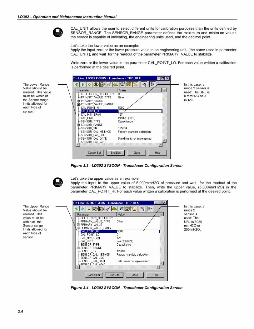
CAL_UNIT allows the user to select different units for calibration purposes than the units defined by SENSOR_RANGE. The SENSOR_RANGE parameter defines the maximum and minimum values the sensor is capable of indicating, the engineering units used, and the decimal point.
Let’s take the lower value as an example: Apply the input zero or the lower pressure value in an engineering unit, (the same used in parameter CAL_UNIT), and wait for the readout of the parameter PRIMARY_VALUE to stabilize.
Write zero or the lower value in the parameter CAL_POINT_LO. For each value written a calibration is performed at the desired point.
Figure 3.3 - LD302 SYSCON - Transducer Configuration Screen
Let’s take the upper value as an example: Apply the input to the upper value of 5,000mmH2O of pressure and wait for the readout of the parameter PRIMARY_VALUE to stabilize. Then, write the upper value, (5,000mmH2O) in the parameter CAL_POINT_HI. For each value written a calibration is performed at the desired point.
Figure 3.4 - LD302 SYSCON - Transducer Configuration Screen
The Lower Range Value should be entered. This value must be within of the Sensor range limits allowed for each type of sensor.
In this case, a range 2 sensor is used: The URL is 0 mmH2O or 0 inH2O.
The Upper Range Value should be entered. This value must be within of the Sensor range limits allowed for each type of sensor.
In this case, a range 2 sensor is used: The URL is 5080 mmH2O or 200 inH2O.

Configuration
3.5
WARNING
It is recommended that a convenient engineering unit be chosen through the XD_SCALE parameter of the Analog Input Block, considering that the range limits of the sensor must be respected. (100% and 0%). It is also recommended for every new calibration, to save existing trim data in parameters CAL_POINT_LO_BACKUP and CAL_POINT_HI_BACKUP, by means of parameter BACKUP_RESTORE, using option LAST_TRIM_BACKUP.
Through Local Adjustment
In order to enter the local adjustment mode, place the magnetic tool in the orifice “Z” until flag “MD” lights up on the display. Remove the magnetic tool from “Z” and place it in orifice “S”. Remove and reinsert the magnetic tool in “S” until the message “LOC ADJ” is displayed. The message will be displayed for approximately 5 seconds after the user removes the magnetic tool from “S”. The upper value is taken as an example:
Apply to the input a pressure of 5,000mmH2O. Wait for the pressure readout of the parameter P_VAL (PRIMARY_VALUE) to stabilize and then set the UPPER parameter until it reads 5,000.
NOTE
The exit of the trim mode on the local adjustment occurs automatically when the magnetic tool is not used for 15 seconds Even when parameters LOWER or UPPER already present the desired value, they must be actuated so that calibration is performed.
Limit Conditions for Calibration: For every writing operation in the transducer blocks there is an indication for the operation associated with the waiting method. These codes appear in parameter XD_ERROR. Every time a calibration is performed. Code 0, for example, indicates a successfully performed operation.
Upper: SENSOR_RANGE_EUO < NEW_UPPER < SENSOR_RANGE_EU100 * 1.25 Otherwise, XD_ERROR = 26. (NEW_UPPER - PRIMARY_VALUE) < SENSOR_RANGE_EU100 * 0.1 Otherwise, XD_ERROR = 27. (NEW_UPPER - CAL_POINT_LO) >CAL_MIN_SPAN * 0,75 Otherwise, XD_ERROR = 26.
NOTE
Codes for XD_ERROR:
16: Default Value Set
22: Out of Range.
26: Invalid Calibration Request.
27: Excessive Correction.
Characterization Trim
It is used to correct the sensor reading in several points.
Use an accurate and stable pressure source, preferably a dead-weight tester. To guarantee the accuracy, the tester should be at least three times more accurate than the transmitter. Wait for the pressure to stabilize before performing the trim.
LD302 – Operation and Maintenance Instruction Manual
3.6
The sensor characteristic curve at a certain temperature and for certain ranges may be slightly nonlinear. This eventual non-linearity may be corrected through the Characterization Trim.
The user may characterize the transmitter throughout the operating range, obtaining even better accuracy.
The characterization is determined from two to five points. Just apply the pressure and inform the transmitter the pressure that is being applied.
WARNING
The characterization trim changes the transmitter characteristics.
Read the instructions carefully and verify that a pressure standard with accuracy of 0.03% or better is being used; otherwise the transmitter accuracy will be seriously affected.
Characterize a minimum of two points. These points will define the characterization curve. The maximum number of points is five. It is recommended to select the points equally distributed over the desired range or over a part of the range where more accuracy is required.
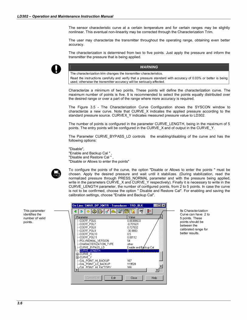
The Figure 3.5 - The Characterization Curve Configuration shows the SYSCON window to characterize a new curve. Note that CURVE_X indicates the applied pressure according to the standard pressure source. CURVEX_Y indicates measured pressure value to LD302.
The number of points is configured in the parameter CURVE_LENGTH, being in the maximum of 5 points. The entry points will be configured in the CURVE_X and of output in the CURVE_Y.
The Parameter CURVE_BYPASS_LD controls the enabling/disabling of the curve and has the following options:
"Disable", "Enable and Backup Cal " , "Disable and Restore Cal " , "Disable or Allows to enter the points"
To configure the points of the curve, the option "Disable or Allows to enter the points " must be chosen. Apply the desired pressure and wait until it stabilizes. (During stabilization, read the normalized pressure through PRESS_NORMAL parameter and with the pressure being applied, write in the parameters CURVE_X and CURVE_Y respectively). Finally it is necessary to write in the CURVE_LENGTH parameter, the number of configured points, from 2 to 5 points. In case the curve is not to be confirmed, choose the option " Disable and Restore Cal". For enabling and saving the calibration settings, choose "Enable and Backup Cal".
Figure 3.5 - The Characterization Curve Configuration
Its Characterization Curve can have 2 to 5 points. These points should be between the calibrated range for better results.
This parameter identifies the number of valid points.

Configuration
3.7
Figure 3.6 - The Characterization Curve Configuration
Sensor Information
The main information about the transmitter can be accessed by selecting the Transducer block icon option as shown in Figure 3.10 - Creating Transducers and Function Blocks. The sensor information will be displayed as shown below.
Figure 3.7 - Transducer Block - Sensor Information
Only application dependent options defined by combo boxes can be changed. (E.g. Flange Type, O' Ring Material, etc.) And the others are only factory configured (e.g. Sensor Isolating Diaphragm, Sensor Fluid, etc.).
This parameter activates or deactivates the Characterization Curve after the points have been configured.
By the list box the user can enable or disable the Characterization Curve, enter the points, restore or backup the curve entered. This parameter should be used preferably by a calibration method.
This parameter assigns the Engineering Units for all parameters related to calibration methods. Usually, they start their names with CAL_UNIT.
The appropriate calibration unit can be chosen by selecting the Engineering Units available for each type of Transducer Block

LD302 – Operation and Maintenance Instruction Manual
3.8
Temperature Trim
Write in the TEMPERATURE_TRIM parameter any value in the range of -40 C to +85 C. After that, check the calibration performance using the SECONDARY_ VALUE parameter.
Figure 3.8 - The Temperature Trim Configuration
Sensor Data Reading
When the transmitter LD302 is on, it is verified that the serial number of the sensor in the sensor board is the same as the recorded serial number in the E2PROM in the main board. When these numbers are different (a swap of sensor set or main board was carried through) the data stored in the E2PROM of the sensor board is copied to the E2PROM of the main board.
Through the parameter BACKUP_RESTORE, this reading can be made, choosing the option "SENSOR_DATA_RESTORE". The operation, in this case, is independent of the sensor serial number. Through the option "SENSOR_DATA_BACKUP", the sensor data stored in the main board EEPROM memory can be saved in the E2PROM of the sensor board. (This operation is done at factory).
Through this parameter, we can recover default data from the factory about sensor and last saved calibration settings, as well as calibrations. These are the following options:
Factory Cal Restore: Recover last calibration settings made at factory; Last Cal Restore: Recover last calibration settings made by user and saved as backup; Default Data Restore: Restore all data as default; Sensor Data Restore: Restore sensor data saved in the sensor board and copy them to
main board EEPROM memory. Factory Cal Backup: Copy the actual calibration settings to the factory ones; Last Cal Backup: Copy the actual calibration settings to the backup ones; Sensor Data Backup: Copy the sensor data at main board EEPROM memory to the
EEPROM memory located at the sensor board; None: Default value, no action is done.
By adjusting this parameter to the current temperature, the device's temperature indication is automatically adjusted.
Usually, its operation is done by a method in the factory.
Configuration
3.9
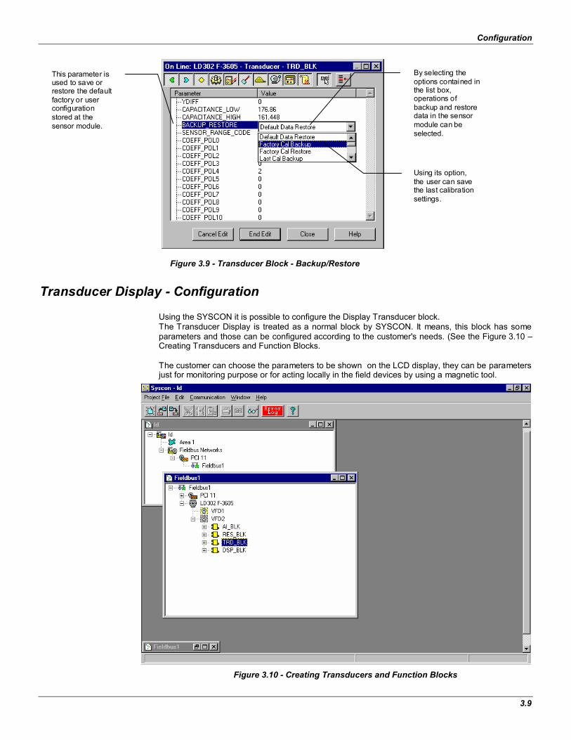
Figure 3.9 - Transducer Block - Backup/Restore
Transducer Display - Configuration
Using the SYSCON it is possible to configure the Display Transducer block. The Transducer Display is treated as a normal block by SYSCON. It means, this block has some parameters and those can be configured according to the customer's needs. (See the Figure 3.10 – Creating Transducers and Function Blocks.
The customer can choose the parameters to be shown on the LCD display, they can be parameters just for monitoring purpose or for acting locally in the field devices by using a magnetic tool.
Figure 3.10 - Creating Transducers and Function Blocks
This parameter is used to save or restore the default factory or user configuration stored at the sensor module.
Using its option, the user can save the last calibration settings.
By selecting the options contained in the list box, operations of backup and restore data in the sensor module can be selected.

LD302 – Operation and Maintenance Instruction Manual
3.10
Display Transducer Block
The local adjustment is completely configured by SYSCON. It means, the user can select the best options to fit his application. From the factory, it is configured with the options to set the Upper and Lower trim, for monitoring the input transducer output and check the Tag. Usually, the transmitter is much better configured by SYSCON, but the local functionality of the LCD allows an easy and fast action on certain parameters, since it does not rely on communication and network wiring connections. Among the possibilities of the Local Adjustment, the following options can be brought out Mode block, Outputs monitoring, Tag visualization and Tuning Parameters setting.
The interaction between the user, is described in detail on the "General Installation, Operation and Maintenance Procedures Manual". Take a detailed look at this manual in the chapter related to "Programming Using Local Adjustment". The resources on this transducer display as well as all of the Series 302 Field Devices from Smar, have the same methodology.
Once trained, the user can handle any kind of field devices from Smar.
All function block and transducers defined according to Foundation Fieldbus have a description of their features written on binary files, by the Device Description Language.
This feature allows that third parties configurator enabled by Device Description Service technology can interpret these features and make them accessible to configure. The Series 302 Function Blocks and Transducers have been defined strictly according the Fieldbus Foundation specifications in order to be interoperable to other parties.
In order to enable the local adjustment using the magnetic tool, it is necessary to prepare the parameters concerning this operation via SYSCON (System Configuration). Figure 3.8 - The Temperature Trim Configuration and Figure 3.9 - Transducer Block - Backup/Restore shows all parameters and their respective values, which should be configured to enable local adjustment through the magnetic screwdriver according to the user’s unit. All values shown on the display are default values.
There are seven groups of parameters, which may be pre-configured by the user in order to enable, a possible configuration by means of the local adjustment. As an example, suppose some parameters are not to be shown; in this case, simply write an invalid Tag in the parameter, Block_Tag_Param_X. By doing this, the device will not take the parameters related (indexed) to its Tag as valid parameters.
Definition of Parameters and Values
Block_Tag_ParamThis is the tag of the block to which the parameter belongs. It uses up to a maximum of 32 characters.
Index_Relative This is the index related to the parameter to be actuated or viewed (0, 1, 2…). Refer to the Function Blocks Manual to know the desired indexes, or see them on the SYSCON by opening the desired block.
Sub_Index To visualize a certain tag, choose for the index relative equal to zero, and for the sub-index equal to one (refer to the paragraph “Structure Block in the Function Blocks Manual)”.
MnemonicThis is the mnemonic for the parameter identification (it accepts a maximum of 16 characters in the alphanumeric field of the display). Choose the mnemonic, with no more than 5 characters, so it will no longer be necessary to rotate it on the display.
Inc_DecIt is the increment and decrement in decimal units when the parameter is Float, Float Status, or integer, when the parameter is in whole units.
Decimal_Point_Numb.This is the number of digits after the decimal point (0 to 3 decimal digits).
Configuration
3.11
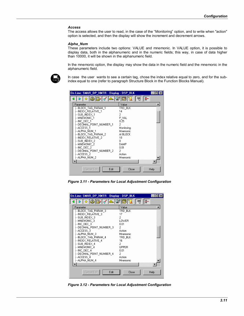
AccessThe access allows the user to read, in the case of the “Monitoring” option, and to write when "action" option is selected, and then the display will show the increment and decrement arrows.
Alpha_NumThese parameters include two options: VALUE and mnemonic. In VALUE option, it is possible to display data, both in the alphanumeric and in the numeric fields; this way, in case of data higher than 10000, it will be shown in the alphanumeric field.
In the mnemonic option, the display may show the data in the numeric field and the mnemonic in the alphanumeric field.
In case the user wants to see a certain tag, chose the index relative equal to zero, and for the sub-index equal to one (refer to paragraph Structure Block in the Function Blocks Manual).
Figure 3.11 - Parameters for Local Adjustment Configuration
Figure 3.12 - Parameters for Local Adjustment Configuration

LD302 – Operation and Maintenance Instruction Manual
3.12
Figure 3.13 - Parameters for Local Adjustment Configuration
Figure 3.14 - Parameters for Local Adjustment Configuration
Configuration
3.13
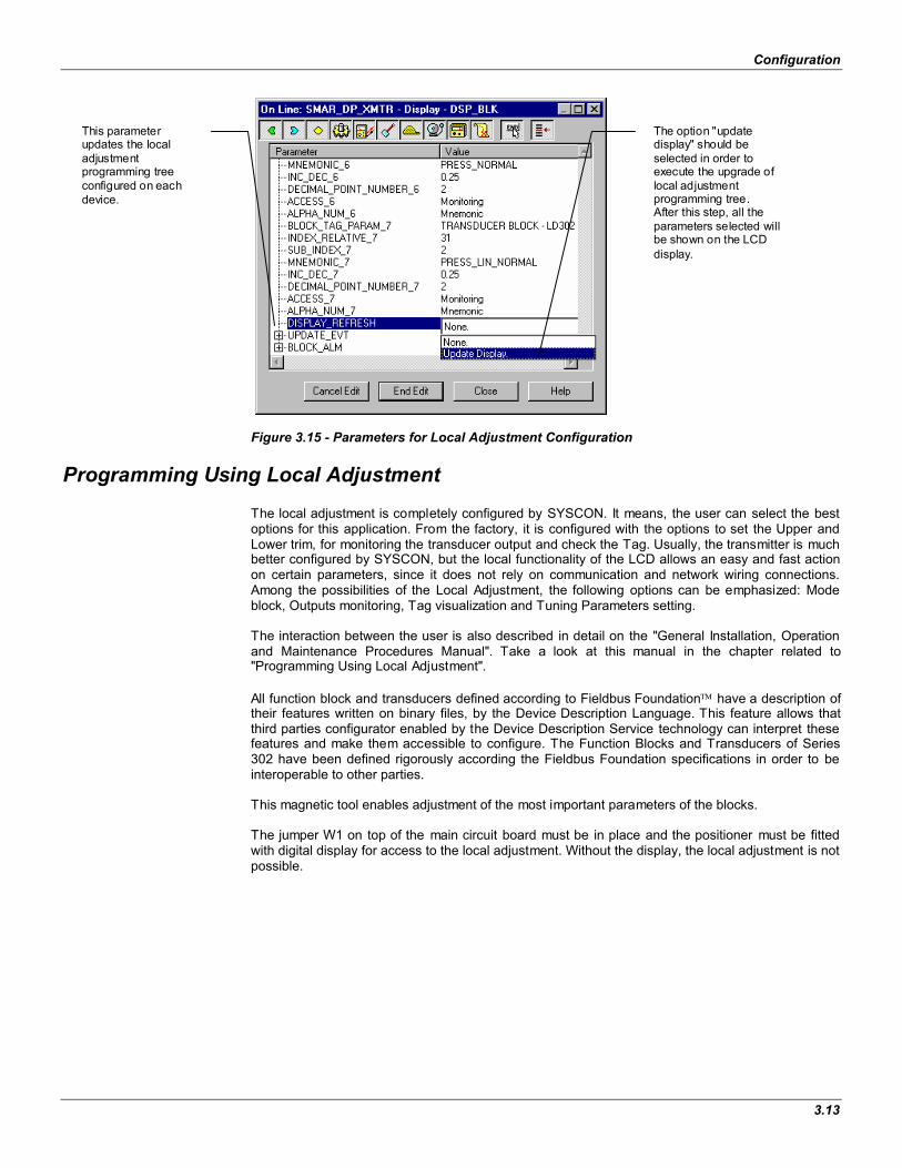
Figure 3.15 - Parameters for Local Adjustment Configuration
Programming Using Local Adjustment
The local adjustment is completely configured by SYSCON. It means, the user can select the best options for this application. From the factory, it is configured with the options to set the Upper and Lower trim, for monitoring the transducer output and check the Tag. Usually, the transmitter is much better configured by SYSCON, but the local functionality of the LCD allows an easy and fast action on certain parameters, since it does not rely on communication and network wiring connections. Among the possibilities of the Local Adjustment, the following options can be emphasized: Mode block, Outputs monitoring, Tag visualization and Tuning Parameters setting.
The interaction between the user is also described in detail on the "General Installation, Operation and Maintenance Procedures Manual". Take a look at this manual in the chapter related to "Programming Using Local Adjustment".
All function block and transducers defined according to Fieldbus Foundation have a description of their features written on binary files, by the Device Description Language. This feature allows that third parties configurator enabled by the Device Description Service technology can interpret these features and make them accessible to configure. The Function Blocks and Transducers of Series 302 have been defined rigorously according the Fieldbus Foundation specifications in order to be interoperable to other parties.
This magnetic tool enables adjustment of the most important parameters of the blocks.
The jumper W1 on top of the main circuit board must be in place and the positioner must be fitted with digital display for access to the local adjustment. Without the display, the local adjustment is not possible.
The option "update display" should be selected in order to execute the upgrade of local adjustment programming tree. After this step, all the parameters selected will be shown on the LCD display.
This parameter updates the local adjustment programming tree configured on each device.
LD302 – Operation and Maintenance Instruction Manual
3.14
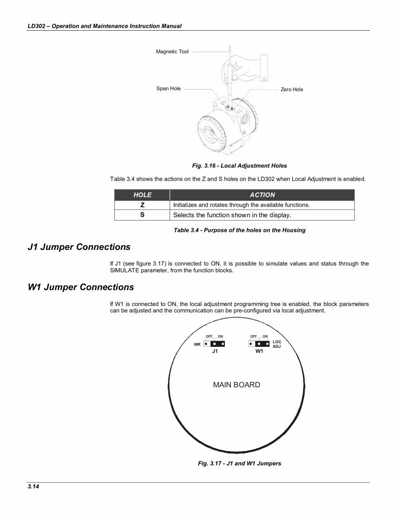
Fig. 3.16 - Local Adjustment Holes
Table 3.4 shows the actions on the Z and S holes on the LD302 when Local Adjustment is enabled.
HOLE ACTIONZ Initializes and rotates through the available functions.
S Selects the function shown in the display.
Table 3.4 - Purpose of the holes on the Housing
J1 Jumper ConnectionsIf J1 (see figure 3.17) is connected to ON, it is possible to simulate values and status through theSIMULATE parameter, from the function blocks.
W1 Jumper ConnectionsIf W1 is connected to ON, the local adjustment programming tree is enabled, the block parameterscan be adjusted and the communication can be pre-configured via local adjustment.
Fig. 3.17 - J1 and W1 Jumpers
MAIN BOARD
WR
J1
OFF ON
W1
LOCADJ
OFF ON
Magnetic Tool
Span Hole Zero Hole
Configuration
3.15
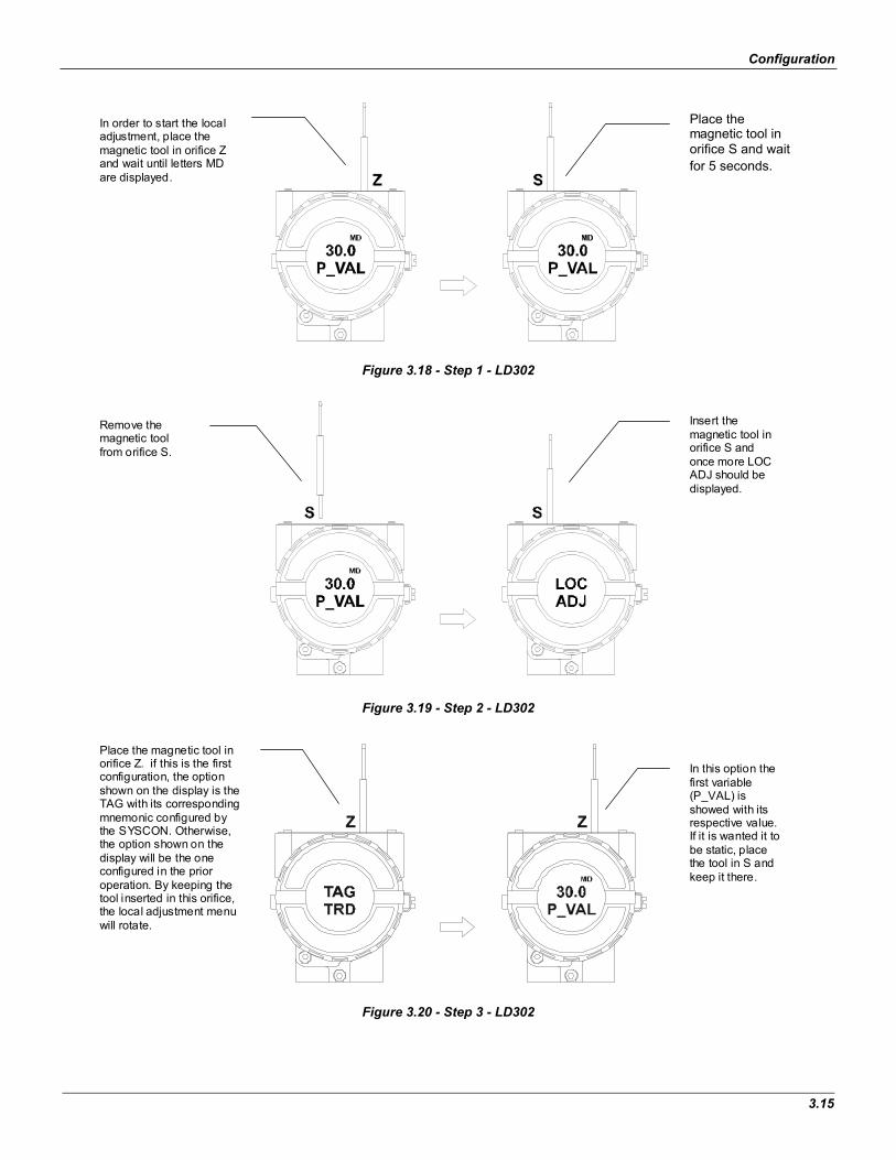
Figure 3.18 - Step 1 - LD302
Figure 3.19 - Step 2 - LD302
Figure 3.20 - Step 3 - LD302
In order to start the localadjustment, place themagnetic tool in orifice Zand wait until letters MDare displayed.
Place themagnetic tool inorifice S and waitfor 5 seconds.
Insert themagnetic tool inorifice S andonce more LOCADJ should bedisplayed.
Remove themagnetic toolfrom orifice S.
In this option thefirst variable(P_VAL) isshowed with itsrespective value.If it is wanted it tobe static, placethe tool in S andkeep it there.
Place the magnetic tool inorifice Z. if this is the firstconfiguration, the optionshown on the display is theTAG with its correspondingmnemonic configured bythe SYSCON. Otherwise,the option shown on thedisplay will be the oneconfigured in the prioroperation. By keeping thetool inserted in this orifice,the local adjustment menuwill rotate.

LD302 – Operation and Maintenance Instruction Manual
3.16
Figure 3.21 - Step 4 - LD302
Figure 3.22 - Step 5 - LD302
NOTE
This Local adjustment configuration is a suggestion only. The user may choose the best configuration via SYSCON, by just configuring the display block (See Programming Using Local Adjustment.)
In order to decrement the lower value, place the magnetic tool in orifice Z to shift the arrow to the downward position and then, by inserting and keeping the tool in orifice S, it is possible to decrement the lower value.
In order to calibrate the lower value(LOWER), insert the magnetic tool in orifice S as soon as LOWER is shown in the display. An arrow pointing upward ( )increments the value and an arrow pointing downward ( )decrements the value. In order to increment the value, keep the tool inserted in S until the desired value is set.
In order to decrement the upper value, place the magnetic tool in orifice Z to shift the arrow to the downward position an then, by insetting and keeping the tool in orifice S, it is possible to decrement the upper value.
In order to calibrate the upper value(UPPER), insert the magnetic tool in orifice S as soon as upper is shown in the display. An arrow pointing upward ( )increments the valve and an arrow pointing downward ( )decrements the value. In order to increment the value, keep the tool inserted in S until the desired value is set.
Section 4
4.1
Maintenance Procedures
General The SMAR Series 302 devices are extensively tested and inspected before delivery to the end user. Nevertheless, during their design and development, consideration has been given to the possibility of repairs being made by the end user, when necessary.
In general, it is recommended that end users do not try to repair printed circuit boards. Spare circuit boards may be ordered from SMAR when necessary. Refer to the item "Returning Materials" at the end of this Section.
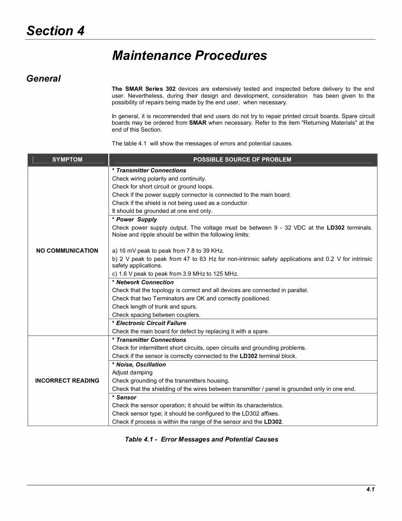
The table 4.1 will show the messages of errors and potential causes.
SYMPTOM POSSIBLE SOURCE OF PROBLEM
* Transmitter Connections
Check wiring polarity and continuity.
Check for short circuit or ground loops.
Check if the power supply connector is connected to the main board.
Check if the shield is not being used as a conductor.
It should be grounded at one end only.
* Power Supply
Check power supply output. The voltage must be between 9 - 32 VDC at the LD302 terminals. Noise and ripple should be within the following limits:
a) 16 mV peak to peak from 7.8 to 39 KHz.
b) 2 V peak to peak from 47 to 63 Hz for non-intrinsic safety applications and 0.2 V for intrinsic safety applications.
c) 1.6 V peak to peak from 3.9 MHz to 125 MHz.
* Network Connection
Check that the topology is correct and all devices are connected in parallel.
Check that two Terminators are OK and correctly positioned.
Check length of trunk and spurs.
Check spacing between couplers.
NO COMMUNICATION
* Electronic Circuit Failure
Check the main board for defect by replacing it with a spare.
* Transmitter Connections
Check for intermittent short circuits, open circuits and grounding problems.
Check if the sensor is correctly connected to the LD302 terminal block.
* Noise, Oscillation
Adjust damping
Check grounding of the transmitters housing.
Check that the shielding of the wires between transmitter / panel is grounded only in one end.
INCORRECT READING
* Sensor
Check the sensor operation; it should be within its characteristics.
Check sensor type; it should be configured to the LD302 affixes.
Check if process is within the range of the sensor and the LD302.
Table 4.1 - Error Messages and Potential Causes

LD302 - Operation and Maintenance Instruction Manual
4.2
If the problem is not stated in the table above, follow the Note below:
NOTE
The Factory Init should be tried as a last option to recover the equipment control when the equipment presents some problem related to the function blocks or the communication. This operation must be offline and carried out only by authorized personnel, , since the equipment will be configured with standard and factory data.
This procedure resets all of the configurations running in the equipment, after which a partial download should be performed.
Two magnetic tools should be used to this effect,. On the equipment, withdraw the nut that affixes the identification tag on the top of the housing, so that access is gained to the "S" and "Z" holes.
The operations to follow are:
1) Switch off the equipment, insert the magnetic tools and keep them in the holes (the magnetic end in the holes);
2) Supply the equipment;
3) As soon as the Factory Init is shown on the display, take off the tools and wait for the "5" symbol on the right upper corner of the display to disappear, thus indicating the end of the operation.
This procedure makes effective all of the factory configuration and will eliminate eventual problems with the function blocks or with the equipment communication.
Disassembly Procedure
WARNING
Do not disassemble with power on.
The Figure 4.4 - Exploded View shows an exploded view of the transmitter and will help to visualize the following:
Sensor Cleaning
In order to have access to the sensor (19) for cleaning purposes, the transmitter should be removed from its process connections. The transmitter should be isolated from the process by means of manifolds or valves; then, the drain (13) must be opened to exhaust any remaining pressure.
Figure 4.1 - Sensor Rotation Stopper
Maintenance Procedures
4.3
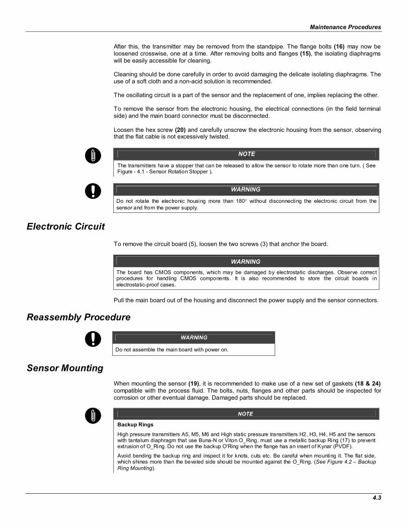
After this, the transmitter may be removed from the standpipe. The flange bolts (16) may now be loosened crosswise, one at a time. After removing bolts and flanges (15), the isolating diaphragms will be easily accessible for cleaning.
Cleaning should be done carefully in order to avoid damaging the delicate isolating diaphragms. The use of a soft cloth and a non-acid solution is recommended.
The oscillating circuit is a part of the sensor and the replacement of one, implies replacing the other.
To remove the sensor from the electronic housing, the electrical connections (in the field terminal side) and the main board connector must be disconnected.
Loosen the hex screw (20) and carefully unscrew the electronic housing from the sensor, observing that the flat cable is not excessively twisted.
NOTE
The transmitters have a stopper that can be released to allow the sensor to rotate more than one turn. ( See Figure - 4.1 - Sensor Rotation Stopper ).
WARNING
Do not rotate the electronic housing more than 180 without disconnecting the electronic circuit from the sensor and from the power supply.
Electronic Circuit
To remove the circuit board (5), loosen the two screws (3) that anchor the board.
WARNING
The board has CMOS components, which may be damaged by electrostatic discharges. Observe correct procedures for handling CMOS components. It is also recommended to store the circuit boards in electrostatic-proof cases.
Pull the main board out of the housing and disconnect the power supply and the sensor connectors.
Reassembly Procedure
WARNING
Do not assemble the main board with power on.
Sensor Mounting
When mounting the sensor (19), it is recommended to make use of a new set of gaskets (18 & 24)compatible with the process fluid. The bolts, nuts, flanges and other parts should be inspected for corrosion or other eventual damage. Damaged parts should be replaced.
NOTE
Backup Rings
High pressure transmitters A5, M5, M6 and High static pressure transmitters H2, H3, H4, H5 and the sensors with tantalum diaphragm that use Buna-N or Viton O_Ring, must use a metallic backup Ring (17) to prevent extrusion of O_Ring. Do not use the backup O'Ring when the flange has an insert of Kynar (PVDF).
Avoid bending the backup ring and inspect it for knots, cuts etc. Be careful when mounting it. The flat side, which shines more than the beveled side should be mounted against the O_Ring. (See Figure 4.2 – Backup Ring Mounting).

LD302 - Operation and Maintenance Instruction Manual
4.4
Gaskets should be lightly lubricated with silicone oil before they are fitted into their recesses. Use halogen grease for inert fill applications. The flanges should then be positioned in order to press them in place. With the flanges holding the O-Rings in place, insert the four bolts (16) and tighten the nuts (23) finger tight, making sure the flanges remain parallel all the time.
Tighten one nut until the flange seats. Tighten the nut diagonally across with a torque of approximately 2.5 kgf.m (20 ft. lbs). Tighten the first nut with the same torque. Verify the flange alignment. Check torque on the four bolts.
If adapters (25) have been removed, it is recommended to replace gaskets (24) and to connect the adapters to the process flanges before coupling them to the sensor. Optimum torque is 2.5 Kgf.m (20 ft. lbs).
The fitting of the sensor must be done with the main board out of the electronic housing. Mount the sensor to the housing turning clockwise until it stops. Then turn it counterclockwise until it faces the protective cover (1) parallel to the process flange. Tighten the hex screw (20) to lock the housing to the sensor.
Figure 4.2 - Backup Ring Mounting
Maintenance Procedures
4.5
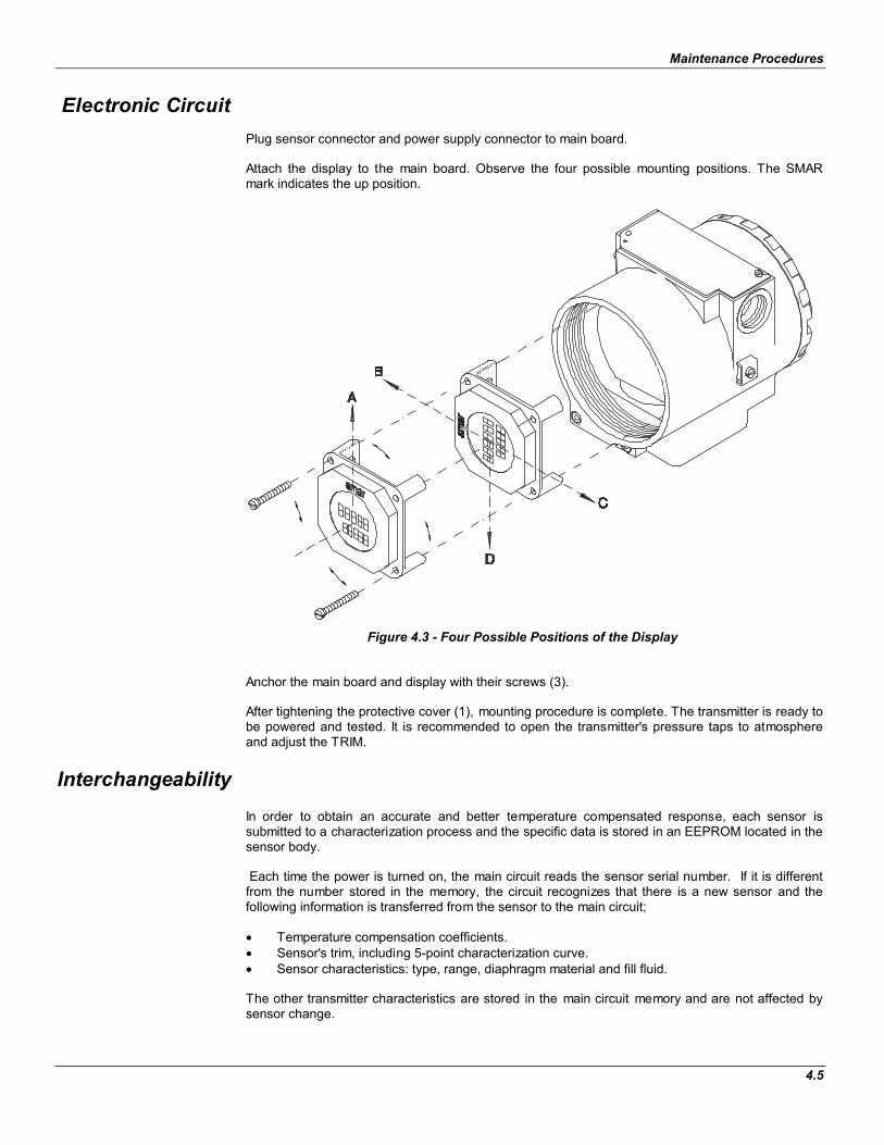
Electronic Circuit
Plug sensor connector and power supply connector to main board.
Attach the display to the main board. Observe the four possible mounting positions. The SMAR mark indicates the up position.
Figure 4.3 - Four Possible Positions of the Display
Anchor the main board and display with their screws (3).
After tightening the protective cover (1), mounting procedure is complete. The transmitter is ready to be powered and tested. It is recommended to open the transmitter's pressure taps to atmosphere and adjust the TRIM.
Interchangeability
In order to obtain an accurate and better temperature compensated response, each sensor is submitted to a characterization process and the specific data is stored in an EEPROM located in the sensor body.
Each time the power is turned on, the main circuit reads the sensor serial number. If it is different from the number stored in the memory, the circuit recognizes that there is a new sensor and the following information is transferred from the sensor to the main circuit;
Temperature compensation coefficients. Sensor's trim, including 5-point characterization curve. Sensor characteristics: type, range, diaphragm material and fill fluid.
The other transmitter characteristics are stored in the main circuit memory and are not affected by sensor change.
LD302 - Operation and Maintenance Instruction Manual
4.6
Upgrading LD301 to LD302
The sensor and housing of the LD301 is exactly the same as the LD302. By changing the circuit board of the LD301 it becomes a LD302. The display on the LD301 version 5.XX, is the same as on LD302 and can therefore be used with the LD302 upgrade circuit board. With an LD301 version three or earlier, that display cannot be used.
Upgrading the LD301 to a LD302 is therefore very much the same as the procedure for replacing the main board described above.
To remove the circuit board (5), loosen the two screws (3) that anchor the board.
Caution with the circuit boards must be as mentioned above.
Pull the LD301 main board out of the housing, disconnect the power supply and the sensor connectors.
Replace the LD302 main board reversing the procedure for removing the LD301 circuit.
Returning Materials
If it becomes necessary to return the transmitter to SMAR, simply contact our office, giving the defective instrument's serial number, and return it to our factory.
In order to speed up analysis and solution of a problem, the defective item should be returned with a description of the failure, with as much detailed information as possible. Other information concerning the instruments’ operation, such as service and process conditions are also helpful.
ACCESSORIES
ORDERING CODE DESCRIPTION
SD1 Magnetic Tool for Local Adjustment
BC1 Fieldbus/RS232 Interface
SYSCON System Configurator
PS302 Power Supply
BT302 Terminator
PCI Process Control Interface

Maintenance Procedures
4.7
Figure 4.4 - Exploded View
LD302 - Operation and Maintenance Instruction Manual
4.8
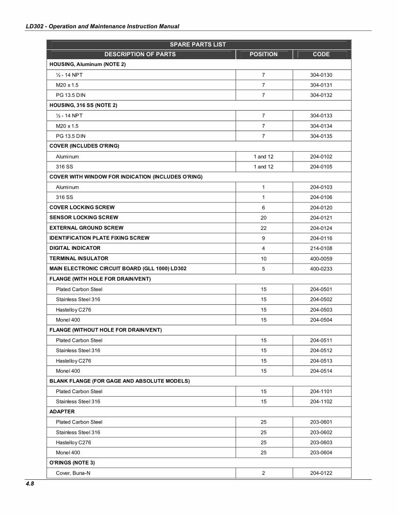
SPARE PARTS LIST
DESCRIPTION OF PARTS POSITION CODE
HOUSING, Aluminum (NOTE 2)
½ - 14 NPT 7 304-0130
M20 x 1.5 7 304-0131
PG 13.5 DIN 7 304-0132
HOUSING, 316 SS (NOTE 2)
½ - 14 NPT 7 304-0133
M20 x 1.5 7 304-0134
PG 13.5 DIN 7 304-0135
COVER (INCLUDES O'RING)
Aluminum 1 and 12 204-0102
316 SS 1 and 12 204-0105
COVER WITH WINDOW FOR INDICATION (INCLUDES O’RING)
Aluminum 1 204-0103
316 SS 1 204-0106
COVER LOCKING SCREW 6 204-0120
SENSOR LOCKING SCREW 20 204-0121
EXTERNAL GROUND SCREW 22 204-0124
IDENTIFICATION PLATE FIXING SCREW 9 204-0116
DIGITAL INDICATOR 4 214-0108
TERMINAL INSULATOR 10 400-0059
MAIN ELECTRONIC CIRCUIT BOARD (GLL 1000) LD302 5 400-0233
FLANGE (WITH HOLE FOR DRAIN/VENT)
Plated Carbon Steel 15 204-0501
Stainless Steel 316 15 204-0502
Hastelloy C276 15 204-0503
Monel 400 15 204-0504
FLANGE (WITHOUT HOLE FOR DRAIN/VENT)
Plated Carbon Steel 15 204-0511
Stainless Steel 316 15 204-0512
Hastelloy C276 15 204-0513
Monel 400 15 204-0514
BLANK FLANGE (FOR GAGE AND ABSOLUTE MODELS)
Plated Carbon Steel 15 204-1101
Stainless Steel 316 15 204-1102
ADAPTER
Plated Carbon Steel 25 203-0601
Stainless Steel 316 25 203-0602
Hastelloy C276 25 203-0603
Monel 400 25 203-0604
O’RINGS (NOTE 3)
Cover, Buna-N 2 204-0122

Maintenance Procedures
4.9
SPARE PARTS LIST
DESCRIPTION OF PARTS POSITION CODE
Neck, Buna-N 21 204-0113
O’RINGS (NOTE 3)
Flange, BUNA-N 18 203-0401
Flange, VITON 18 203-0402
Flange, TEFLON 18 203-0403
Flange, ETHYLENE/PROPYLENE 18 203-0404
Flange, TEFLON with spring LOADED 18 203-0405
Adapter, BUNA-N 24 203-0701
Adapter, VITON 24 203-0702
Adapter, TEFLON 24 203-0703
Adapter, ETHYLENE/PROPYLENE 24 203-0704
BACKUP RING (NOTE 3) 17 203-0710
TERMINAL HOLDING SCREW.
Housing in Aluminum 11 304-0119
Housing in 316 Stainless Steel 11 204-0119
MAIN BOARD SCREW HOUSING IN ALUMINUM
Units with indicator 3 304-0118
Units without indicator 3 304-0117
MAIN BOARD SCREW HOUSING IN 316 STAINLESS STEEL
Units with indicator 3 204-0118
Units without indicator 3 204-0117
FLANGE BOLT
Carbon Steel 16 203-0300
Stainless Steel 316 16 203-0310
FLANGE NUT
Carbon Steel 23 203-0302
Stainless Steel 316 23 203-0312
ADAPTER BOLT
Carbon Steel 26 203-0350
Stainless Steel 316 26 203-0351
DRAIN/VENT SCREW
Stainless Steel 316 13 203-1401
Hastelloy C276 13 203-1402
Monel 400 13 203-1403
FLANGE PLUG (STOPPER)
Stainless Steel 316 14 203-0552
Hastelloy C276 14 203-0553
Monel 400 14 203-0554
MOUNTING BRACKET FOR 2” PIPE MOUNTING (NOTE 5)
Carbon Steel - 203-0801
Stainless Steel 316 - 203-0802
Carbon Steel with bolts, nuts, washers and U-clamp in 316SS - 203-0803
LOCAL ADJUSTMENT PROTECTION CAP 8 204-0114
SENSOR 19 (NOTE 4)
Table 4.2 - Spare Part List
LD302 - Operation and Maintenance Instruction Manual
4.10
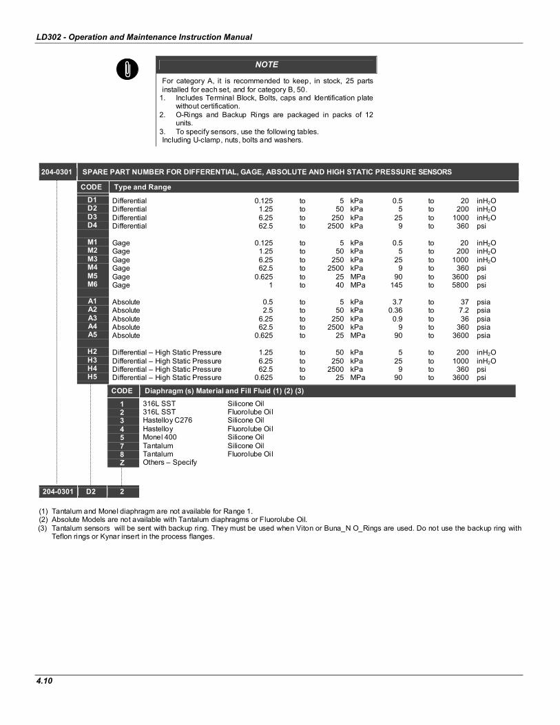
NOTE
For category A, it is recommended to keep, in stock, 25 parts installed for each set, and for category B, 50.
1. Includes Terminal Block, Bolts, caps and Identification plate without certification.
2. O-Rings and Backup Rings are packaged in packs of 12 units.
3. To specify sensors, use the following tables. Including U-clamp, nuts, bolts and washers.
204-0301 SPARE PART NUMBER FOR DIFFERENTIAL, GAGE, ABSOLUTE AND HIGH STATIC PRESSURE SENSORS
CODE Type and Range
D1 D2 D3 D4
M1 M2 M3 M4 M5 M6
A1 A2 A3 A4 A5
H2 H3 H4 H5
Differential 0.125 to 5 kPa 0.5 to 20 inH2ODifferential 1.25 to 50 kPa 5 to 200 inH2ODifferential 6.25 to 250 kPa 25 to 1000 inH2ODifferential 62.5 to 2500 kPa 9 to 360 psi
Gage 0.125 to 5 kPa 0.5 to 20 inH2OGage 1.25 to 50 kPa 5 to 200 inH2OGage 6.25 to 250 kPa 25 to 1000 inH2OGage 62.5 to 2500 kPa 9 to 360 psi Gage 0.625 to 25 MPa 90 to 3600 psi Gage 1 to 40 MPa 145 to 5800 psi
Absolute 0.5 to 5 kPa 3.7 to 37 psia Absolute 2.5 to 50 kPa 0.36 to 7.2 psia Absolute 6.25 to 250 kPa 0.9 to 36 psia Absolute 62.5 to 2500 kPa 9 to 360 psia Absolute 0.625 to 25 MPa 90 to 3600 psia
Differential – High Static Pressure 1.25 to 50 kPa 5 to 200 inH2ODifferential – High Static Pressure 6.25 to 250 kPa 25 to 1000 inH2ODifferential – High Static Pressure 62.5 to 2500 kPa 9 to 360 psi Differential – High Static Pressure 0.625 to 25 MPa 90 to 3600 psi
CODE Diaphragm (s) Material and Fill Fluid (1) (2) (3)
1234578Z
316L SST Silicone Oil 316L SST Fluorolube Oil Hastelloy C276 Silicone Oil Hastelloy Fluorolube Oil Monel 400 Silicone Oil Tantalum Silicone Oil Tantalum Fluorolube Oil Others – Specify
204-0301 D2 2
(1) Tantalum and Monel diaphragm are not available for Range 1. (2) Absolute Models are not available with Tantalum diaphragms or Fluorolube Oil.
(3) Tantalum sensors will be sent with backup ring. They must be used when Viton or Buna_N O_Rings are used. Do not use the backup ring with Teflon rings or Kynar insert in the process flanges.

Maintenance Procedures
4.11
204-0301 SPARE PART NUMBER FOR LEVEL SENSORS
CODE Range
L2 L3 L4
Level 1.25 to 50 kPa 5 to 200 inH2OLevel 6.25 to 250 kPa 25 to 1000 inH2OLevel 62.5 to 2500 kPa 9 to 360 psi
CODE Diaphragm Material and Fill Fluid (Low Side)
1234578Z
316L SST Silicone Oil 316L SST Fluorolube Oil Hastelloy C276 Silicone Oil (1)Hastelloy C276 Fluorolube Oil (1)Monel 400 Silicone Oil Tantalum Silicone Oil Tantalum Fluorolube Oil Others – Specify
CODE Flange, Adapter and Drain/Vent Valves Material (Low Side)
CIHNZ
Plated CS (Drain/Vent in Stainless Steel) 316L SST Hastelloy C276 (1)316 SST (Drain/Vent in Hastelloy C276) (1)Others – Specify
CODE Wetted O-Rings Material (Low Side)
0BVTZ
Without O-Rings (Remote Seal) Buna N Viton Teflon Others – Specify
CODE Drain/Vent Position (Low Side)
0U
D
Without Drain/Vent Note: For better drain/vent operation, the side vent or drain valves are standard . Upper If drain/vent valves are not required, use code 0. Lower
CODE Process Connection (Low Side)
019Z
1/4 - 18 NPT (Without Adapter) 1/2 - 14 NPT (With Adapter) Remote Seal (Specify) Others – Specify
CODE Process Connection (High Side)
12346789
3" 150# (ANSI B16.5 RF) 3" 300# (ANSI B16.5 RF) 4" 150# (ANSI B16.5 RF) 4" 300# (ANSI B16.5 RF) DN 80 PN 25/40 DN 100 PN 10/16 DN 100 PN 25/40 2" 150# (ANSI B16.5 RF)
ABCDEZ
2" 300# (ANSI B16.5 RF) 2" 600# (ANSI B16.5 RF) 3" 600# (ANSI B16.5 RF) 4" 600# (ANSI B16.5 RF) DN 50 PN 10/40 Others – Specify
CODE Extension Length
01234Z
0 mm 50 mm (2”) 100 mm (4”) 150 mm (6”) 200 mm (8”) Others - Specify
CODE Diaphragm Material (High Side)
12345Z
316L SST Hastelloy C276 (1)Monel 400 (2)Tantalum Titanium Others – Specify
CODE Fill Fluid (High Side)
123AZ
DC200 Silicone Oil Fluorolube Oil DC704 Silicone Oil DC200/350 Silicone Oil Others – Specify
CODE Options Items*
A1C1 ZZ
316 SST Bolts and Nuts Special Cleaning Special Options – Specify
204-0301 L2 1 I B U 1 3 2 2 1 *
(1) Meets NACE material recommendations per MR-01-75 (2) Fluorolube fill fluid is not available for Monel Diaphragm. (*) Leave it blank for no optional items.
Note: With 316L SST extension.

LD302 - Operation and Maintenance Instruction Manual
4.12

Section 5
5.1
Technical Characteristics
Functional Specifications
Process Fluid Liquid, gas or vapor.
Output SignalDigital only. Fieldbus, 31.25 kbit/s voltage mode with bus power.
Power SupplyBus power 9 - 32 VDC. Quiescent Current consumption: 12 mA. Output impedance: non-intrinsic safety from 7.8 kHz - 39 kHz should be greater or equal to 3 kOhm. Intrinsic safety output impedance: (assuming an IS barrier in the power supply) from 7.8 kHz - 39 kHz should be greater than or equal to 400 Ohm.
IndicatorOptional 4½-digit numerical and 5-character alphanumerical LCD indicator.
Hazardous Area CertificationsExplosion proof, weather proof and intrinsically safe (CENELEC and FM standards).
Temperature Limits
Ambient: -40 to 85 C (-40 to 185 F).Process: -40 to 100 C (-40 to 212 F) (Silicone Oil). 0 to 85 C (-32 to 185 F) (Fluorolube Oil). -40 to 150 C (-40 to 302 F) for LD302L. -25 to 85 C (-13 to 185 F) (Viton O-Rings). Storage: -40 to 100 C (-40 to 212 F).Display: -10 to 60 C ( 14 to 140 F) operation. -40 to 85 C (-40 to 185 F) without damage.
Turn-on TimePerforms within specifications on less than 5.0 seconds after power is applied to the transmitter.
Volumetric DisplacementLess than 0.15 cm
3 (0.01 in3).
Overpressure and Static Pressure LimitsFrom 3.45 kPa abs. (0.5 psia)* to:
8 MPa (1150 psi) for range 1. 16 MPa (2300 psi) for ranges 2, 3, 4 & 5. 32 MPa (4600 psi) for models H & A5. 40 MPa (5800 psi) for model M5. 52 MPa (7500 psi) for model M6.
* except the LD302A model.
For ANSI/DIN Level flanges (LD302L models): 150 lb Flanges: 6 psia to 275 psi at 100°F. 300 lb Flanges: 6 psia to 720 psi at 100°F. 600 lb Flanges: 6 psia to 1440 psi at 100°F. PN10/16: -60 kPa to 2,8 MPa at 38°C. PN25/40: -60 kPa to 9 MPa at 38°C.
These overpressures will not damage the transmitter, but a new calibration may be necessary. Flange Test Pressure: 60 MPa (8570 psi).
Humidity Limits0 to 100% RH.

LD302 - Operation and Maintenance Instruction Manual
5.2
Performance Specifications
Reference conditions: range starting at zero, temperature 25 C (77 F), atmospheric pressure, power supply of 24 Vdc, silicone oil fill fluid, isolating diaphragms in 316L SS and digital trim equal to lower and upper range values.
Accuracy
±0.075% of span (for span 0.1 URL). ±0.0375 [1+ (0.1 URL/SPAN)]% of span (for span < 0.1 URL).
For range 5 and 6, Absolute models, diaphragms in Tantalum, Monel or fill fluid in Fluorolube:
±0.1% of span (for span 0.1 URL). ±0.05 [1+ (0.1 URL/SPAN)]% of span (for span < 0.1 URL).
For Absolute - range 1: ±0.2% of span
Linearity, hysteresis and repeatability effects are included.
Stability±0.1% of URL for 24 months for ranges 2, 3, 4, 5 & 6. ±0.2% of URL for 12 months for range 1 & L models.
±(0.25% of URL for 5 years at 20 C temperature change and up to 70 bar of static pressure.
Temperature Effect±(0.02% × URL+0.1% × span) per 20 C (36 F) for ranges 2, 3, 4 & 5.
±(0.05% × URL+0.15% × span) per 20 C (36 F) for range 1 & level models.
Static Pressure EffectZero error: ±0.1% URL per 7 MPa (1000 psi) for ranges 2, 3, 4 & 5 or 3.5 MPa (500 psi) for L models. ±0.1% URL per 1.7 MPa (250 psi) for range 1.
This is a systematic error that can be eliminated by calibrating at the operating static pressure.
Span error: Correctable to ±0.2% of reading per 7 MPa (1000 psi) for ranges 2, 3, 4 and 5, and 3.5 MPa (500 psi) for range 1 and level models.
Power Supply Effect±0.005% of calibrated span per volt.
Mounting Position EffectZero shift of up to 250 Pa (1 inH2O), which can be calibrated out. No span effect.
Electro-Magnetic Interference EffectDesigned to comply with IEC 801.
Physical Specifications
Electrical Connection½ -14 NPT, Pg 13.5, or M20 × 1.5 metric. Other connections upon request.
Process Connection¼ -18 NPT or ½ -14 NPT (with adapter). For L models see Ordering Code.
Wet Parts
Isolating Diaphragms316L SST, Hastelloy C276, Monel 400 or Tantalum.

Technical Characteristics
5.3
Drain/Vent Valves and Plug316 SST, Hastelloy C276 or Monel 400.
FlangesPlated carbon steel, 316 SST, Hastelloy C276 or Monel 400.
Wetted O-Rings (For Flanges and Adapters)Buna N, Viton™ or PTFE. Ethylene-Propylene on request.
The LD302 is available in materials according to NACE MR-01-75.
Non-wet Parts
Electronic HousingInjected aluminum with polyester painting or 316 SST (NEMA 4X, IP67).
Blank FlangePlated carbon steel, when the wetted flange is made of this same material, and 316 SST in the other cases.
Level Flange (LD302L) Material316 SST.
Fill FluidSilicone or Fluorolube Oil.
Cover O-RingsBuna N.
Mounting BracketPlated carbon steel with polyester painting or 316 SST. Accessories (bolts, nuts, washers and U-clamp) in carbon steel or 316 SST.
Flange Screws, Bolts and nutsPlated carbon steel, Grade 7 or 316 SST.
Identification Plate316 SST.
Mountinga) Flange mounted for models LD302L.b) Optional universal mounting bracket for surface or vertical/horizontal 2"-pipe (DN 50). c) Via bracket on manifold valve (Optional). d) Directly on tube for closely coupled transmitter/ orifice flange combinations.
Approximate Weights3.15 kg (7 lb) : all models, except level transmitters. 5.85 to 9.0 kg (13 lb. to 20 lb): level transmitter depending on the flanges, extension and materials.
Hastelloy is a trademark of the Cabot Corp. Viton and Teflon are trademarks of E. I. DuPont de Nemours & Co. Fluorolube is a trademark of Hooker Chemical Corp. Monel is a trademark of International Nickel Co.
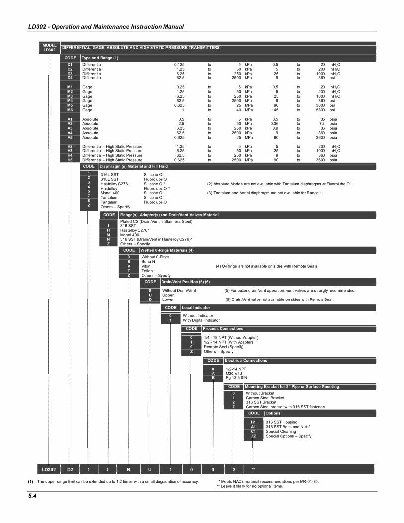
LD302 - Operation and Maintenance Instruction Manual
5.4
MODEL LD302
DIFFERENTIAL, GAGE, ABSOLUTE AND HIGH STATIC PRESSURE TRANSMITTERS
CODE Type and Range (1)
D1 D2 D3 D4
M1 M2 M3 M4 M5 M6
A1 A2 A3 A4 A5
H2 H3 H4 H5
Differential 0.125 to 5 kPa 0.5 to 20 inH2ODifferential 1.25 to 50 kPa 5 to 200 inH2ODifferential 6.25 to 250 kPa 25 to 1000 inH2ODifferential 62.5 to 2500 kPa 9 to 360 psi
Gage 0.25 to 5 kPa 0.5 to 20 inH2OGage 1.25 to 50 kPa 5 to 200 inH2OGage 6.25 to 250 kPa 25 to 1000 inH2OGage 62.5 to 2500 kPa 9 to 360 psi Gage 0.625 to 25 MPa 90 to 3600 psi Gage 1 to 40 MPa 145 to 5800 psi
Absolute 0.5 to 5 kPa 3.5 to 35 psia Absolute 2.5 to 50 kPa 0.36 to 7.2 psia Absolute 6.25 to 250 kPa 0.9 to 36 psia Absolute 62.5 to 2500 kPa 9 to 360 psia Absolute 0.625 to 25 MPa 90 to 3600 psia
Differential – High Static Pressure 1.25 to 5 kPa 5 to 200 inH2ODifferential – High Static Pressure 6.25 to 50 kPa 25 to 1000 inH2ODifferential – High Static Pressure 62.5 to 250 kPa 9 to 360 psia Differential – High Static Pressure 0.625 to 2500 MPa 90 to 3600 psia
CODE Diaphragm (s) Material and Fill Fluid
1234578Z
316L SST Silicone Oil 316L SST Fluorolube Oil Hastelloy C276 Silicone Oil* (2) Absolute Models are not available with Tantalum diaphragms or Fluorolube Oil. Hastelloy Fluorolube Oil* Monel 400 Silicone Oil (3) Tantalum and Monel diaphragm are not available for Range 1.Tantalum Silicone Oil Tantalum Fluorolube Oil Others – Specify
CODE Flange(s), Adapter(s) and Drain/Vent Valves Material
IHMNZ
Plated CS (Drain/Vent in Stainless Steel) 316 SST Hastelloy C276* Monel 400 316 SST (Drain/Vent in Hastelloy C276)* Others – Specify
CODE Wetted 0-Rings Materials (4)
0BVTZ
Without 0-Rings Buna N Viton (4) O-Rings are not available on sides with Remote Seals. Teflon Others – Specify
CODE Drain/Vent Position (5) (6)
0UD
Without Drain/Vent (5) For better drain/vent operation, vent valves are strongly recommended. Upper Lower (6) Drain/Vent valve not available on sides with Remote Seal.
CODE Local Indicator
01
Without Indicator With Digital Indicator
CODE Process Connections
019Z
1/4 - 18 NPT (Without Adapter) 1/2 - 14 NPT (With Adapter) Remote Seal (Specify) Others – Specify
CODE Electrical Connections
0AB
1/2-14 NPT M20 x 1.5 Pg 13.5 DIN
CODE Mounting Bracket for 2" Pipe or Surface Mounting
0127
Without Bracket Carbon Steel Bracket 316 SST Bracket Carbon Steel bracket with 316 SST fasteners
CODE Options
H1 A1 C1 ZZ
316 SST Housing 316 SST Bolts and Nuts* Special Cleaning Special Options – Specify
LD302 D2 1 I B U 1 0 0 2 **
(1) The upper range limit can be extended up to 1.2 times with a small degradation of accuracy. * Meets NACE material recommendations per MR-01-75. ** Leave it blank for no optional items.

Technical Characteristics
5.5
MODEL LD302 LEVEL TRANSMITTERS
CODE Range
L2 L3 L4
Level 1.25 to 50 kPa 5 to 200 inH2OLevel 6.25 to 250 kPa 25 to 1000 inH2OLevel 62.5 to 2500 kPa 9 to 360 psi
CODE Diaphragm Material and Fill Fluid (Low Side)
1234578Z
316L SST Silicone Oil 316L SST Fluorolube Oil Hastelloy C276 Silicone Oil* Hastelloy C276 Fluorolube Oil* Monel 400 Silicone Oil Tantalum Silicone Oil Tantalum Fluorolube Oil Others – Specify
CODE Flange, Adapter and Drain/Vent Valves Material (Low Side)
CIHMZ
Plated CS (Drain/Vent in Stainless Steel) 316L SST Hastelloy C276* Monel 400 Others – Specify
CODE Wetted 0-Rings Material (Low Side)
0BVTZ
Without 0-Rings (Remote Seal) Buna N Viton Teflon Others – Specify
CODE Drain/Vent Position (Low Side)
0U
D
Without Drain/Vent Note: For better drain/vent operation, the side vent or drain valves are standard . Upper If drain/vent valves are not required, use code 0. Lower
CODE Local Indicator
01
Without Indicator With Digital Indicator
CODE Process Connection (Low Side)
019Z
1/4 - 18 NPT (Without Adapter) 1/2 - 14 NPT (With Adapter) Remote Seal (Specify) Others – Specify
CODE Electrical Connections
0ABZ
1/2-14 NPT M20 x 1.5 Pg 13.5 DIN Others – Specify
CODE Process Connection (High Side)
12346789
3" 150# (ANSI B16.5 RF) 3" 300# (ANSI B16.5 RF) 4" 150# (ANSI B16.5 RF) 4" 300# (ANSI B16.5 RF) DN 80 PN 25/40 DN 100 PN 10/16 DN 100 PN 25/40 2" 150# (ANSI B16.5 RF)
ABCDEZ
2" 300# (ANSI B16.5 RF) 2" 600# (ANSI B16.5 RF) 3" 600# (ANSI B16.5 RF) 4" 600# (ANSI B16.5 RF) DN 50 PN 10/40 Others – Specify
CODE Extension Length
01234Z
0 mm 50 mm (2") Note: With 316L SST extension. 100 mm (4") 150 mm (6") 200 mm (8") Others – Specify
CODE Diaphragm Material (High Side)
12345Z
316L SST Hastelloy C276* Monel 400** Tantalum Titanium Others – Specify
CODE Fill Fluid (High Side)
123AZ
DC200 Silicone Oil Fluorolube Oil DC704 Silicone Oil DC200/350 Silicone Oil Others – Specify
CODE Options
H1 A1C1 ZZ
316 SST Housing 316 SST Bolts and Nuts* Special Cleaning Special Options – Specify
LD302 L2 1 C Z U 1 0 A 1 2 1 3 ***
* Meets NACE material recommendations per MR-01-75 ** Fluorolube fill fluid is not available for Monel Diaphragm. *** Leave it blank no optionals items.
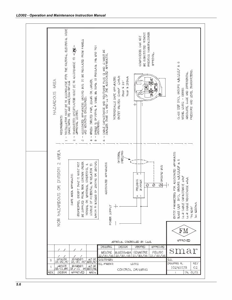
LD302 - Operation and Maintenance Instruction Manual
5.6