INTRODUCTION - Home - National Association of City … · · 2011-03-14INTRODUCTION This Toolkit...
32
INTRODUCTION This Toolkit is provided as a supplement to national bicycle facility planning and design guidelines, such as the AASHTO Guide for the Development of Bicycle Facilities, 1999, the Manual on Uniform Traffic Control Devices, and the SHA Maryland Bicycle and Pedestrian Design Guide (expected publication 2006). It should be used in conjunction with the basic bicycle facility design guides mentioned above and with other publications developed by national transportation engineering organizations to describe best practices in bicycle facility design. In older East Coast cities--which have narrower rights-of-way, variable street and intersection patterns, and diverse street parking conditions--the implementation of standard on-street bicycle facility designs can be a challenge. The purpose of this Toolkit is to provide the Department of Transportation, Baltimore- specific design guidance that can be useful in addressing these challenges. This Toolkit addresses a select set of topics that are both typical within, and generally unique to Baltimore. The Toolkit has been developed in conjunction with the City of Baltimore Bicycle Master Plan (hereafter referred to as the Master Plan). The Master Plan provides an overall planning and policy framework for future development of bicycle facilities in the City. The Toolkit provides standard design details, a route signing protocol, and strategic guidance to be used by City staff, traffic engineers, facility designers and planners in implementation of many of the bicycling accommodations recommended in the Master Plan. It is divided into the following three sections: Section 1: Standard Design Details This section provides seven design details where the specifics of facility design may be uniform (or relatively so) when applied in similar settings throughout the city. Moreover, the Standard Design Details are provided in a format that is more easily duplicated for direct integration into design and construction plan sets. The first 5 details are applications of standards found in AASHTO and the MUTCD adapted to the City of Baltimore setting. Details 6 and 7 are based upon proposals that are currently before the NCUTCD 1 for inclusion into the MUTCD. There are ongoing experiments with these devices in other jurisdictions around the country. Section 2: Bicycle Route Signing Protocol This section provides comprehensive guidance for the planning and design of on-street bicycle route signing within the City of Baltimore. The sign protocol is based upon existing MUTCD guidance with the exception of the sign design. The sign design is based upon a proposal currently before the NCUTCD for inclusion into the MUTCD. A close variation of this sign design is currently utilized in the City of Chicago. The NCUTCD proposal is based upon the City of Chicago design. Section 3: Strategic Guidance This section provides example strategies that may be considered by engineers who are attempting to retrofit existing Baltimore Streets to improve bicycle accommodation. It addresses ten roadway retrofit situations that are common to Baltimore. Since specific geometric or land use conditions vary frequently from location to location, this retrofit guidance may not be useful in every situation that is 1 NCUTCD – The National Committee on Uniform Traffic Control Devices (NCUTCD) or the "National Committee" is an organization whose purpose is to assist in the development of standards, guides and warrants for traffic control devices and practices used to regulate, warn and guide traffic on streets and highways. The NCUTCD recommends to the Federal Highway Administration (FHWA) and to other appropriate agencies proposed revisions and interpretations to the Manual on Uniform Traffic Control Devices (MUTCD) and other accepted national standards. (From NCUTCD homepage – http://www.ncutcd.org/purpose.shtml) 1
Transcript of INTRODUCTION - Home - National Association of City … · · 2011-03-14INTRODUCTION This Toolkit...
INTRODUCTION This Toolkit is provided as a supplement to national bicycle facility planning and design guidelines, such as the AASHTO Guide for the Development of Bicycle Facilities, 1999, the Manual on Uniform Traffic Control Devices, and the SHA Maryland Bicycle and Pedestrian Design Guide (expected publication 2006). It should be used in conjunction with the basic bicycle facility design guides mentioned above and with other publications developed by national transportation engineering organizations to describe best practices in bicycle facility design. In older East Coast cities--which have narrower rights-of-way, variable street and intersection patterns, and diverse street parking conditions--the implementation of standard on-street bicycle facility designs can be a challenge. The purpose of this Toolkit is to provide the Department of Transportation, Baltimore-specific design guidance that can be useful in addressing these challenges. This Toolkit addresses a select set of topics that are both typical within, and generally unique to Baltimore. The Toolkit has been developed in conjunction with the City of Baltimore Bicycle Master Plan (hereafter referred to as the Master Plan). The Master Plan provides an overall planning and policy framework for future development of bicycle facilities in the City. The Toolkit provides standard design details, a route signing protocol, and strategic guidance to be used by City staff, traffic engineers, facility designers and planners in implementation of many of the bicycling accommodations recommended in the Master Plan. It is divided into the following three sections:
Section 1: Standard Design Details This section provides seven design details where the specifics of facility design may be uniform (or relatively so) when applied in similar settings throughout the city. Moreover, the Standard Design Details are provided in a format that is more easily duplicated for direct integration into design and construction plan sets. The first 5 details are applications of standards found in AASHTO and the MUTCD adapted to the City of Baltimore setting. Details 6 and 7 are based upon proposals that are currently before the NCUTCD1 for inclusion into the MUTCD. There are ongoing experiments with these devices in other jurisdictions around the country. Section 2: Bicycle Route Signing Protocol This section provides comprehensive guidance for the planning and design of on-street bicycle route signing within the City of Baltimore. The sign protocol is based upon existing MUTCD guidance with the exception of the sign design. The sign design is based upon a proposal currently before the NCUTCD for inclusion into the MUTCD. A close variation of this sign design is currently utilized in the City of Chicago. The NCUTCD proposal is based upon the City of Chicago design. Section 3: Strategic Guidance This section provides example strategies that may be considered by engineers who are attempting to retrofit existing Baltimore Streets to improve bicycle accommodation. It addresses ten roadway retrofit situations that are common to Baltimore. Since specific geometric or land use conditions vary frequently from location to location, this retrofit guidance may not be useful in every situation that is
1 NCUTCD – The National Committee on Uniform Traffic Control Devices (NCUTCD) or the "National Committee" is an organization whose purpose is to assist in the development of standards, guides and warrants for traffic control devices and practices used to regulate, warn and guide traffic on streets and highways. The NCUTCD recommends to the Federal Highway Administration (FHWA) and to other appropriate agencies proposed revisions and interpretations to the Manual on Uniform Traffic Control Devices (MUTCD) and other accepted national standards. (From NCUTCD homepage – http://www.ncutcd.org/purpose.shtml)
Page 1

encountered. It is not a design standard, and should not be used as such. Application of each retrofit concept requires the use of engineering judgment while utilizing a flexible approach to develop a solution that enhances bicycle accommodation within the constraints of the retrofit project. The discussion for each retrofit situation provides a range of options for consideration during the design process. The City of Baltimore is encouraged to consider developing before and after studies when implementing ideas in this guidance. The City is also encouraged to follow the MUTCD experimentation process when implementing new traffic control devices that are not in the MUTCD.2
It should also be noted that, short of formal experimentation, there is a fairly wide variety of options within the national bicycle planning and design guidelines, particularly related to the appearance of symbols, signs and pavement markings. The City of Baltimore may choose to review the existing options and develop a uniform appearance for bicycle facility traffic controls. While complete uniformity is not required by the national guidance, this may help ensure that a clear message is being relayed to the public as well as simplifying design and installation options, and reducing maintenance costs. The national guidance addresses some of these options in the following locations:
• Pavement Marking Symbols and Text AASHTO Guide for the Development of Bicycle Facilities, 1999, Page 31 Manual on Uniform Traffic Control Devices, 2003, Page 9C-8
• Bicycle Related Signing Manual on Uniform Traffic Control Devices, 2003, Page 9B-1 to 9B-13
• Bicycle Lane Striping AASHTO Guide for the Development of Bicycle Facilities, 1999, Page 24 to 30 Manual on Uniform Traffic Control Devices, 2003, Page 9C-1 to 9C-7
While this toolkit seeks to provide design guidance that is customized for the City of Baltimore it includes treatments utilized successfully in various cities around the country, including San Francisco, Chicago, Philadelphia and Washington, DC. It is not intended to address every topic related to bicycle facility design. Nor does it reiterate the basic design guidelines and principals that are available in the national resources noted above. The reader is encouraged to become familiar with these references and other standard guidance documents that address roadway, street, bikeway and pedestrian facility design.
2 The MUTCD recognizes that traffic control devices must evolve to better solve existing problems or to address new problems. The MUTCD provides an experimentation process (Section 1A.10) to assess the effectiveness of new or unconventional applications of existing devices to provide engineers flexibility. Where flexible approaches are required to create a bicycle friendly roadway, the City is encouraged to utilize the experimentation process established within the MUTCD to assess and analyze the design.
Page 2
Contents Section One – Standard Design Details:
1. Mid-Block Bicycle Lane Striping Adjacent to Parking – page 4
2. Mid-Block Bicycle Lane Striping Adjacent to Curb – page 5
3. Bicycle Safe Stormwater Grates – page 6
4. Placement of Bicycle Parking Racks – page 7
5. Bicycle Detection at Signalized Intersections – page 8
6. Shared Lane Pavement Marking – page 9
7. “Bike May Use Full Lane” Sign – page 10
Section Two – Bicycle Route Signing
1. Bicycle Route Signing Protocol – page 11 Section Three – Strategic Guidance
1. Potential for Bicyclists to Collide with Open Doors of Parked Vehicles (Dooring) – page 16
2. Bicycle Parking – page 18
3. Newly Constructed Bicycle Facilities – page 20
4. Sharing the Road – page 21
5. Bicycle Facilities with Peak Hour Restricted Parking – page 23
6. Contra Flow Bicycle Facilities – page 24
7. Exclusive Bus and Bicycle Lanes – page 26
8. Restricted Street Entries for Motor Vehicles – page 28
9. Advanced Bicycle Boxes at Intersections – page 29
10. Reallocation of Right-of-Way Width for Accommodating Bicyclists – page 31 Section Four – Bibliography
1. Bibliography – page 32
Page 3


Bicycle Route Signing Guidelines Purpose To implement Recommendation 1.2 of the Baltimore Bicycle Transportation Master Plan, the City will identify and sign select Bicycle Routes to improve wayfinding among popular destinations in the city. A system of signed bicycle routes will advance bicycle transportation and recreation in the following ways:
1. Provide a set of spine routes that will be easy to follow…for novice bicyclists, new bicycle commuters, new city residents, and tourists.
2. Provide a set of spine routes that touch every Ward and serve the most important destinations needing bicycle access and wayfinding guidance.
3. Contribute to the physical and visual presence of bicycle facilities on the City street and roadway system, which alerts motorists and all other users of the transportation system that bicyclists have “a right to the road,” and are to be expected along these and other routes throughout the City.
4. Provide a discrete, yet citywide, feature of the bicycling infrastructure that can be used as the lead feature for bicycle marketing and promotion efforts.
Approach For a signed bicycle route network to function effectively, be understood and help bicyclists it must be based on consistent patterns of sign design and usage, i.e. it must be guided by a sign protocol. This protocol will establish the following features of the sign system:
• Hierarchy of routes and facility types • Informational elements to be included, such as direction arrows, place names, distance, and
special facility identification logos • A consistent pattern of sign usage along a route that provides Bike Route Signs, marks route
turns, crossing routes, etc. • Standard sign panel formats and combinations
This protocol also addresses detailed design and logistical issues
• Design of graphics—symbols and logos and how they are used • Colors and how they are used • Sign sizes • Fonts styles and sizes • Ensuring legibility • Support and post materials and method options • Recommended posting locations in the streetscape
The objectives of the sign protocol are as follows:
• To ensure continuity and consistency in features that need to communicate the same message to users regardless of location.
• To allow enough flexibility to address the wide variety of transportation facilities and neighborhood settings that a bicycle route may pass through.
• To provide variable features that are used to communicate meaningful distinctions. • To ensure uniformity in features that may allow for bulk production of some signs and thus lower
capital and maintenance costs. • To ensure that the signs and messages that they communicate are visible, clear, unambiguous,
timely, useful and unlikely to contribute to unsafe or dangerous bicycle movements.
Page 11

Draft Protocol Signage Approach for a Hierarchy of Routes and Facility Types
1. Regular On-Street Bike Routes will use a modified version (D11-1a) of the Bicycle Route signs provided in the Manual on Uniform Traffic Control Devices (MUTCD). Additional and modified protocols are described below. See Detail Sheet for graphic examples.
2. Special On-Street Bike Routes can be created at the Transportation Department’s discretion to feature a route because it has a) a unique service area or destination that is served, b) a community partnership associated with the route, or c) is intended to be marketed to and provided especially for visitors to the City. The Collegetown Bike Route is the first example of such a route.
a. These routes should use the modified on-street route sign (D11-1b) that includes the route/partnership logo and special destination reference, i.e. each sign on the Collegetown route will include the name of the next school to be encountered on the route.
b. No other variations should be necessary. 3. On-Street Trails and Transitions: At locations where shared use path systems continue on city
streets the On-Street Bike Route signage system should be used, with the following elements (See D11-1c and D11-1d):
a. Include the bicycle and pedestrian symbol graphics and text as shown on the Detail Sheet.
b. The sign can be modified to show the appropriate graphics and text in variable situations, i.e. when the route is on-street and uses a shared lane pavement marking instead of a bike lane, the shared lane marking can be used in the sign graphic with the wording “SHARE THE ROAD” instead of the bike graphic and wording “USE BIKE LANE”.
c. Include the appropriate trail logo on a separate panel. 4. Pathway/Bike Route Linkages: At locations where these trails connect to the on-street bicycle
route network the On-Street Bike Route signage system should be used to provide route name, destinations, directional arrows, etc.
5. Major Trails: The shared use paths that are within the City Park System should continue to use the existing signage system, developed for the Gwynns Falls Trail, for all trails throughout the system, using a unique graphic trail logo for each distinct trail. This protocol may be used for interim signage at the discretion of the Departments of Parks & Recreation and Transportation.
Other Sign Types Used Other sign types used will include the following:
• MUTCD Arrow Subplates: M7-1 through M7-7 • MUTCD Facility Label Plates: D1-1c • MUTCD Bike Parking: D4-3 • MUTCD Route Beginning and Ending: M4-11 & M4-12 • Customized signs to address unique situations, as needed.
Route Labeling Routes should always be named using a relatively known place reference that is at the end of the route in that direction of travel. Technically, each route will have two names, one for each direction of travel, however, many routes may use Downtown, or Inner Harbor as the ultimate destination in one direction. The unique name used for the opposite direction will likely become the commonly used route name. A text reference to the ultimate destination for each direction of travel on the route will be provided on each sign used for that direction of travel.
Page 12

Ultimate destination references should be carefully selected. They may be a city neighborhood, a neighborhood or suburb just outside the city, a prominent street, a prominent institution, a park, or other know or easily located landmark. Sign Types, Purposes and Locations Sign plans should be developed using the following sign types, purposes and locations (See detail sheet for example signs).
• Bike Route Sign (D11-1a), provided at confirmation locations (see below) or if confirmation locations are infrequent, approximately every 0.25 miles.
• Junction/Intersection (D1-1b) with other signed bike route or shared use path • Turn in the route (use MUTCD arrow plates, or arrow integrated into Bike Route Sign) • Confirmation (D11-1a), provided within 200 feet after a turn in the route or after a signed
approach has joined or crossed the route. • Approaches to the Route (D11-1a, with M7-5 arrow, or other arrow), provided at
intersection, on select crossing streets (such as arterials, collectors, streets used by many bicyclists) to alert bicyclists of the signed route.
• Transitions (D11-1d), provided where facility types change (trail continues on street in bike lanes and on sidewalk) and/or bicycle/pedestrian positioning on the facility needs to shift.
• In-Street/Pavement Route Marking to be used when a sign on the right may not effectively communicate critical information, such as a left turn in the route.
Informational elements such as directions, place names, distance and units used Both on-street and park trails should provide directional arrows and destination place names at key intersections (all intersections along a trail). Distance to the destination in miles should also be provided. Mileage format should be “X.X” for distances with a fraction of a mile and “X” for whole miles.
• The on-street sign system may use arrow sub-plates or include an arrow on the main sign, as appropriate.
• On-route destinations and mileage should be provided periodically on a sub-plate with an arrow; • The turning point to important side destinations should be marked periodically on a sub-plate
with an arrow. • At the crossing or merging points of two bike routes the bicycle symbol should be included on the
side destination sub-plate to indicate that a signed-route will be provided to the destination.
Sign Details Generally, sign details will meet the requirements established in other guidelines, standards and specifications as appropriate including the MUTCD, American Association of State Highway and Transportation Officials (AASHTO) Roadside Design Guide, Maryland State Highway Administration and City of Baltimore standards and specifications.
• Sign Panel Details such as sign color, size, fonts, graphics/symbols, panel layout and panel combinations should be in accordance with the MUTCD unless otherwise modified by these guidelines.
Page 13
• Sign Location along shared use paths should be in accordance with the MUTCD. Signs located along urban roadways should be located behind the face of curb a minimum of 1.5 feet and in accordance with the AASHTO Roadside Design Guide. Care should be taken to assure that signs are easily seen by cyclists and will not frequently be blocked by parked vehicles, queuing traffic or other obstructions. Signs should be located prior to intersections or decision points where turns are required to give sufficient time to make a decision.
• Sign Support Details should be in accordance with the City of Baltimore or Maryland State Highway Administration Standards as applicable. Mounting signs to steel posts, wood posts, existing utility/signal poles, or other structures is generally acceptable unless otherwise contradicted by the above mentioned guidelines.
• Supplemental Pavement Markings may be advantageous in some situations such as complex intersections or junctions. Directional arrows or the Shared Lane Pavement Markings may be appropriate and should be designed in accordance with the MUTCD and these guidelines. (See Shared Lane Pavement Marking detail).
Note The NCUTCD is currently revising Section 9B.19 and 9B.21 to create a more flexible guide sign. The design of the signs in this route signing protocol is based upon the designs developed for inclusion in the 2008 MUTCD.
Page 14

Bicycle Route Signing Guidelines (Detail Sheet)
Page 15
Page 16
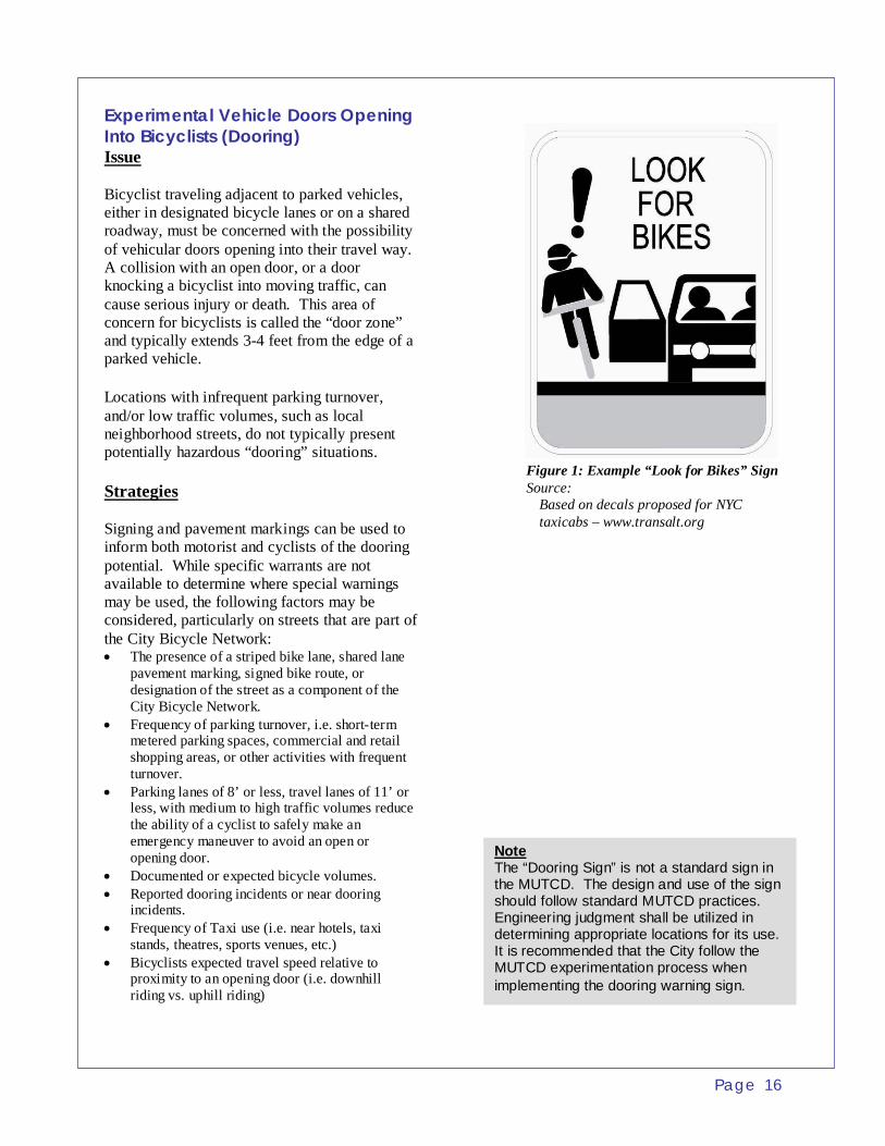
Experimental Vehicle Doors Opening Into Bicyclists (Dooring) Issue Bicyclist traveling adjacent to parked vehicles, either in designated bicycle lanes or on a shared roadway, must be concerned with the possibility of vehicular doors opening into their travel way. A collision with an open door, or a door knocking a bicyclist into moving traffic, can cause serious injury or death. This area of concern for bicyclists is called the “door zone” and typically extends 3-4 feet from the edge of a parked vehicle. Locations with infrequent parking turnover, and/or low traffic volumes, such as local neighborhood streets, do not typically present potentially hazardous “dooring” situations. Strategies Signing and pavement markings can be used to inform both motorist and cyclists of the dooring potential. While specific warrants are not available to determine where special warnings may be used, the following factors may be considered, particularly on streets that are part of the City Bicycle Network: • The presence of a striped bike lane, shared lane
pavement marking, signed bike route, or designation of the street as a component of the City Bicycle Network.
• Frequency of parking turnover, i.e. short-term metered parking spaces, commercial and retail shopping areas, or other activities with frequent turnover.
• Parking lanes of 8’ or less, travel lanes of 11’ or less, with medium to high traffic volumes reduce the ability of a cyclist to safely make an emergency maneuver to avoid an open or opening door.
• Documented or expected bicycle volumes. • Reported dooring incidents or near dooring
incidents. • Frequency of Taxi use (i.e. near hotels, taxi
stands, theatres, sports venues, etc.) • Bicyclists expected travel speed relative to
proximity to an opening door (i.e. downhill riding vs. uphill riding)
Figure 1: Example “Look for Bikes” Sign Source:
Based on decals proposed for NYC taxicabs – www.transalt.org
Note The “Dooring Sign” is not a standard sign in the MUTCD. The design and use of the sign should follow standard MUTCD practices. Engineering judgment shall be utilized in determining appropriate locations for its use. It is recommended that the City follow the MUTCD experimentation process when implementing the dooring warning sign.

Page 17
Experimental Vehicle Doors Opening Into Bicyclists (Dooring) (Continued) Strategy One - Signs: The Look for Bikes sign can be used to alert drivers of parked vehicles to look for oncoming cyclists prior to opening the driver side door (see Figure 1). These signs may be located along the curb line adjacent to the parking lane. Strategy Two - Parking Lane Width: A parking lane width of 9’or greater coupled with drivers’ practice of parking close to the curb (typical in Baltimore), provides more room for a bicyclist to travel outside of the “door zone” and be passed comfortably by vehicles in the adjacent travel lane. Strategy Three - Mark the “Door Zone” in the Bike Lane: Figure 2 shows how diagonal “tic-marks” can be added to the right side of a bike lane to alert bicyclists of the door zone. Some communities have added the text Door Zone to the pavement marking design every 50-100 feet. Standard Detail 1 shows how a bike lane may be offset from a parking lane to reduce door zone conflicts. Standard Detail 6 shows how the shared lane pavement marking may be offset from a parking lane to reduce door zone conflicts. Strategy Four – Education Campaign: An active public education campaign to raise awareness about the risk of dooring. This may include handing out stickers for use on rear view or side view mirrors that remind drivers to “Watch for Bikes” when turning or opening car doors (Figure 3). It may also include a sticker campaign for the backs of taxi seats to warn customers to look before opening a door onto a public street or sidewalk.
Figure 2: Door Zone Pavement Marking Source: San Francisco Bicycle Plan Design Guidelines.
Note The door zone pavement marking is not a standard marking in the MUTCD. The door zone pavement marking shown in Figure 2 is a variation of the standard parking space markings found in the MUTCD (Section 3B.18). It is recommended that the City follow the MUTCD experimentation process when implementing the modified pavement marking layout to depict door zones.
Figure 3: Example “Look for Bikes” Decal Source:
City of Cambridge, MA education campaign. Decal is sent out with parking permits.

Page 18
Bicycle Parking Issue Lack of convenient, safe and weather protected bicycle parking is a major disincentive to bicycle use. Conveniently located and secure bicycle parking facilities are needed throughout Baltimore City. Strategies Bicycle parking may be provided in public spaces throughout the City. The City may also require private building managers and commercial/retail property owners to provide bicycle parking. All bicycle parking may be designated by prominent signage, and utilize safe functional and attractive equipment.
The basic piece of bicycle parking equipment is the bicycle rack. However not all bicycle racks on the market meet the appropriate design requirements (figure 5). A good bicycle rack design includes the following features: • Support the bicycle frame in at least two
places • Allow the frame and wheel to be locked
using a U-lock or cable lock. • Prevent the wheel of the bicycle from
tipping over and not damage the bicycle. • Be durable and securely anchored. • Allow front-in or back-in parking.
Strategy One – Short Term Bicycle Parking: Short term bicycle parking generally means the use of a bicycle rack. Whenever possible, bicycle racks may be covered by a shelter or roof overhang, to provide the additional convenience of weather protection.
Strategy Two – Medium Term Bicycle Parking: Bike parking equipment such as that shown in Figure 7 provides greater security and weather protection, than a basic bike rack. However, because the service requirements of bicycle lockers are not necessary (prior arrangements, long term commitment, rental fees, and key deposits), greater protection can be offered on a first come first serve basis.
Figure 4: Desirable Bicycle Rack Designs
Figure 6: Covered Bicycle Parking
Figure 5: Dish Rack Style – Not Acceptable

Page 19
Bicycle Parking (Continued) Medium-term bike parking is an effective way to meet the needs of non-regular bike commuters, such as at transit stations, universities and other locations where parking durations increase the need for weather protection and/or added security, but bicycle lockers may be too costly and difficult to manage.
Strategy Three – Long Term Bicycle Parking: Employees or students who ride regularly, often need parking accommodations that provide even greater security and weather protection because their bikes remain parked for longer periods of time. This can be provided with bike lockers, indoor bicycle storage rooms or fenced bicycle parking areas in school yards or parking garages. Table 1 presents characteristics associated with the various types of bicycle parking equipment and facilities. It can be used to select the best equipment for the type of location and bicyclists to be served.
Figure 8: Bike Lockers
Figure 7: Bike Lid
Table 1: Bicycle Parking Equipment Characteristics

Page 20
Newly Constructed Bicycle Facilities Issue When on-road bicycle facilities are newly constructed, roadway users must go through a learning period to fully understand the changes and exactly what the new bicycle signage, symbols and markings mean. During this time period, inappropriate maneuvers by drivers and bicyclists may be more frequent. Strategies A coordinated and timely effort to educate the public about changes to a transportation facility may shorten the public’s learning period, make road users feel more comfortable with and accepting of the changes, and improve overall safety. Strategy One – Construction Information Signs: This strategy involves placing construction information signs to inform the public that changes have occurred and explain what the new symbols, signage and markings mean. Details for these construction signs and their locations would be included in the construction staging/maintenance of traffic section of the design plans. These signs would be in place for approximately thirty to sixty days following the implementation of the new facility. Strategy Two – Other Public Outreach: The public information effort can be supported through other types of outreach strategies such as using variable message signs, providing information on City websites, at design public meetings, and in handouts for civic associations and neighborhood groups, etc.
Figure 9: Example Awareness Signs Source: TDG Image Created for Baltimore
New Traffic Pattern Ahead – Virginia DOT Share the Road and Bike Lane Sign
Note: Temporary traffic control (TTC) devices are a found in the Chapter 6 of the MUTCD. These signs are based upon the principal of providing information to roadway users as detailed in Section 6F.55 of the MUTCD for variable message boards following the principals set forth in Chapter 6 of the MUTCD for TTC devices. It is recommended that the City follow the MUTCD experimentation process when implementing these new bicycle facility awareness signs.

Page 21
Sharing the Road Issue Due to the relatively high speed differentials between bicycles and vehicular traffic, there is frequently a need to warn drivers to watch for slower forms of traffic sharing the roadway. There may also be the need to inform bicyclist of where they may be located within a shared roadway for safest operation or to simply make it clear that bicyclists are allowed to use the road
In some situations, shared roadways serve as a link in a bicycle route network where a more desirable facility can’t be implemented due to some type of constraint, i.e. a few blocks that are too narrow for bike lanes on a road that otherwise has them designated at each end.
Shared roadways may also serve as a transition for bicyclists where a dedicated bicycle facility terminates onto a roadway appropriate for bicycle use.
Shared roadways may also serve as a transition for bicyclists where a dedicated bicycle facility, such as a bicycle lane, terminates onto a roadway appropriate for bicycle use. “Share the Road” signs should be used to identify these transition locations.
Strategies Strategy One - Share the Road Signs: “Share the Road” signs can be used to inform drivers that slower forms of traffic are using the roadway. It also warns bicyclists that they will be required to share travel lanes with motor vehicles. “Share the Road” signs can be used on roads within the bicycle route network or locations outside the network that are deemed appropriate, i.e. a road suitable for shared use that may be encountering inappropriate driver behavior. “Share the Road” signs may only be used on roads that have no dedicated space for bicyclists and they are not for use in designating signed bike routes. There is currently a wide variety of “Share the Road” sign types in use around the country. It’s
recommended that the City of Baltimore examine possible sign options to choose the variation most appropriate for the City. It is recommended that the City follow the MUTCD experimentation process if implementing a non-standard sign type.
Figure 11: Variation of the “Share the Road” Sign Source: TDG Photo – Route 6A, Cape Cod Massachusetts
Non MUTCD sign used in Massachusetts
Figure 10: “Share the Road” Signs Source: MUTCD, Part 9

Page 22
Sharing the Road (Continued) Strategy Two - Bike May Use Full Lane Signs: “Bikes May Use Full Lane” signs are used on shared roadways where travel lanes are too narrow for bicycles and vehicles to operate side by side (9’ to 11’ travel lane). They inform the bicyclist that they can or may operate towards the center of the travel lane for safest operation. (See Bicycle Design Guide Details for “Bike May Use Full Lane” sign details).
Strategy Three – Shared Lane Marking: The shared lane pavement marking is typically used where a bike lane is desired but can not be implemented due to insufficient roadway width or other constraint. Use of the shared lane marking would be applicable in the following situations: • In a wide lane (12’ or greater) on a two lane
roadway. • In the right lane of a 4 to 6 lane arterial. • On a signed bike route where lane widths
narrow (12’ or less) or where traffic volumes and speeds are relatively high, possibly in conjunction with “Share the Road” signs.
• For route continuity between sections of roadway where a more desirable facility can’t be implemented.
• Within a shared bus/bicycle lane. The pavement marking warns the motorist of the presence of bicycles while helping the bicyclist determine which the part of the road they may use to be most visible to drivers, and to help avoid conflicts with parked cars. It can also serve to identify a link in a bicycle route network and assist in wayfinding. See Bicycle Design Guide Detail 6.
Periodic use of the “Share the Road” sign is recommended to accompany the Shared lane marking. If share the road signs are used, they may be located immediately adjacent to the pavement marking and may include a downward arrow (45 degrees down and left) pointing directly at the symbol, making it clear what the symbol means.
The strategies presented above can be implemented individually or in conjunction with
one another. Also, refer to the MDSHA Bicycle and Pedestrian Guidelines for further policies regarding shared roadways.
Figure 13: Shared Lane Pavement Marking Source: TDG Photo from San Francisco.
The marking is currently under consideration by the NCUTCD for inclusion in the MUTCD. It was adopted by the California DOT.
Note The shared lane marking and the “Bikes May Use Full Lane” sign are currently under consideration by the NCUTCD for inclusion in the MUTCD. It is recommended that the City follow the MUTCD experimentation process when implementing these new traffic control devices. The shared lane marking symbols are currently in use in Cambridge, San Francisco, Portland, and Colorado Springs.
Figure 12: “Bike May Use Full Lane” Sign Source: NCUTCD
The sign is currently under consideration by the NCUTCD for inclusion in the MUTCD.
Page 23
Bicycle Facilities with Peak Hour Restricted Parking Issue
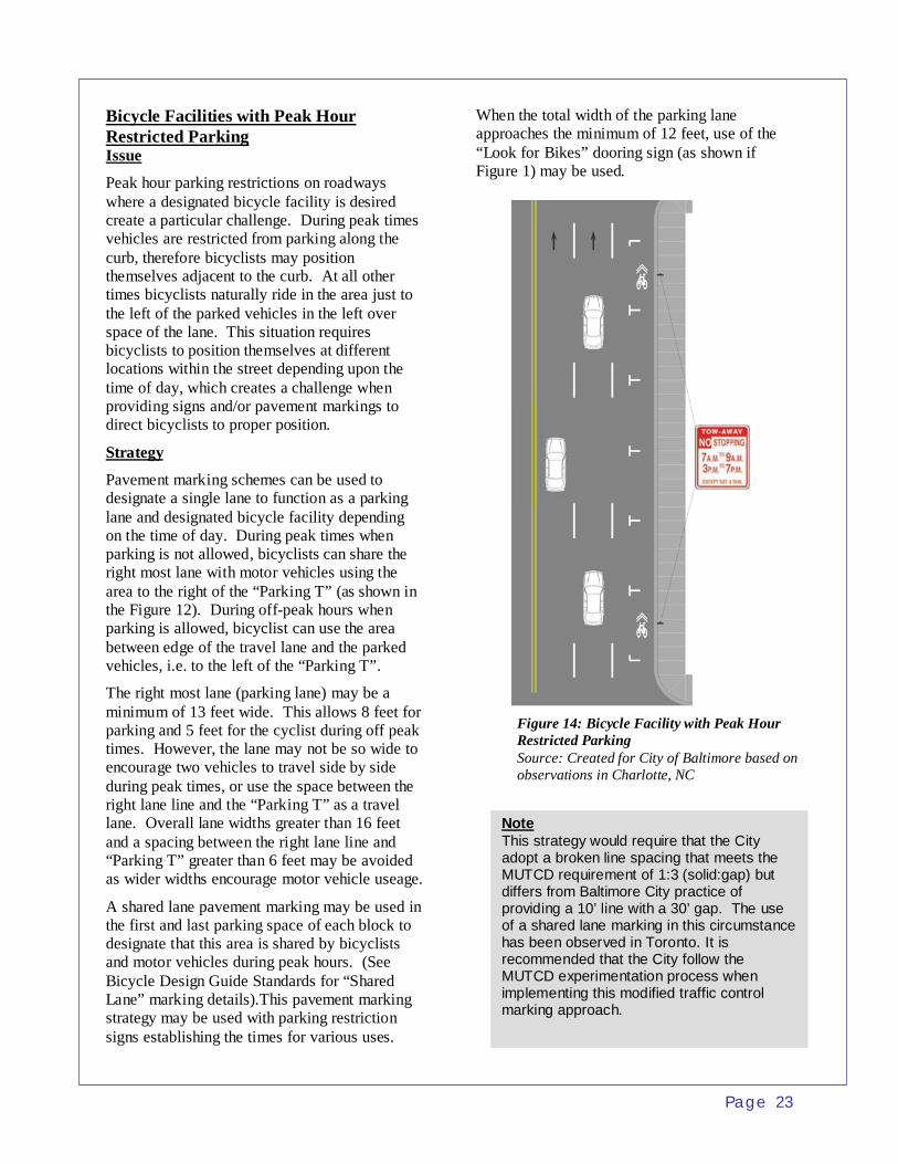
Peak hour parking restrictions on roadways where a designated bicycle facility is desired create a particular challenge. During peak times vehicles are restricted from parking along the curb, therefore bicyclists may position themselves adjacent to the curb. At all other times bicyclists naturally ride in the area just to the left of the parked vehicles in the left over space of the lane. This situation requires bicyclists to position themselves at different locations within the street depending upon the time of day, which creates a challenge when providing signs and/or pavement markings to direct bicyclists to proper position. Strategy
Pavement marking schemes can be used to designate a single lane to function as a parking lane and designated bicycle facility depending on the time of day. During peak times when parking is not allowed, bicyclists can share the right most lane with motor vehicles using the area to the right of the “Parking T” (as shown in the Figure 12). During off-peak hours when parking is allowed, bicyclist can use the area between edge of the travel lane and the parked vehicles, i.e. to the left of the “Parking T”.
The right most lane (parking lane) may be a minimum of 13 feet wide. This allows 8 feet for parking and 5 feet for the cyclist during off peak times. However, the lane may not be so wide to encourage two vehicles to travel side by side during peak times, or use the space between the right lane line and the “Parking T” as a travel lane. Overall lane widths greater than 16 feet and a spacing between the right lane line and “Parking T” greater than 6 feet may be avoided as wider widths encourage motor vehicle useage.
A shared lane pavement marking may be used in the first and last parking space of each block to designate that this area is shared by bicyclists and motor vehicles during peak hours. (See Bicycle Design Guide Standards for “Shared Lane” marking details).This pavement marking strategy may be used with parking restriction signs establishing the times for various uses.
When the total width of the parking lane approaches the minimum of 12 feet, use of the “Look for Bikes” dooring sign (as shown if Figure 1) may be used.
Figure 14: Bicycle Facility with Peak Hour Restricted Parking Source: Created for City of Baltimore based on observations in Charlotte, NC
Note This strategy would require that the City adopt a broken line spacing that meets the MUTCD requirement of 1:3 (solid:gap) but differs from Baltimore City practice of providing a 10’ line with a 30’ gap. The use of a shared lane marking in this circumstance has been observed in Toronto. It is recommended that the City follow the MUTCD experimentation process when implementing this modified traffic control marking approach.

Page 24
Contra-Flow Bicycle Facilities Issue Two-way bicycling accommodations are sometimes necessary on one-way roads because directing bicyclists to an adjacent street is not possible, would be inconvenient, or would make wayfinding difficult.
Providing two-way bicycle accommodations on a one-way street creates a “contra-flow” situation—i.e. a situation where one direction of bicycle travel will be going against motor vehicle traffic unaccompanied by parallel motor vehicle traffic. These situations are challenging from a design and operations standpoint due to the potential for conflicts and fact that motorists may not be expecting on-coming bicyclists.
However, in many cases, signing, pavement markings, special signalization and/or traffic calming measures can be used to help cyclists and drivers operate safely within contra-flow sections. Careful consideration shall be given to all alternative routings before implementing a contra flow facility. An engineering study shall be performed for all contra flow facilities to determine appropriate traffic control measures. Strategies
To implement a safe and effective contra-flow bicycle facility a variety of factors shall be considered, including: • street classification– generally contra-flow
facilities are not applicable on arterials or streets with posted speeds above 25 mph.
• the character of the street, i.e. is it a residential neighborhood street, or a street with retail or commercial establishments, etc.
• the street width and length of contra-flow section needed
• typical vehicle speeds, traffic volumes, posted speed limits and nature of existing traffic flow
• parking regulations and typical turnover
rate, number of connecting streets and driveways within the proposed contra-flow section
• needs for emergency vehicle access, maintenance vehicles such as garbage trucks, and other street uses
Figure 16: Example Contra-Flow Signage. Source: San Francisco Bicycle Design Guideline
Figure 15: Example Contra-Flow Signage. Source: MUTCD
One Way (R6-1) Do Not Enter (R5-1)
Note Contra flow facilities are not recommended as a solution unless there is no other alternative. Special consideration should be given to providing signs that can effectively warn all roadway users of the potentially unexpected bicycle travel pattern. It is recommended that the City follow the MUTCD experimentation process when implementing new signs such as those shown in Figure 16.
Page 25
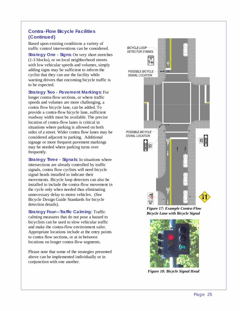
Contra-Flow Bicycle Facilities (Continued) Based upon existing conditions a variety of traffic control interventions can be considered. Strategy One - Signs: On very short stretches (1-3 blocks), or on local neighborhood streets with low vehicular speeds and volumes, simply adding signs may be sufficient to inform the cyclist that they can use the facility while warning drivers that oncoming bicycle traffic is to be expected.
Strategy Two - Pavement Markings: For longer contra-flow sections, or where traffic speeds and volumes are more challenging, a contra flow bicycle lane, can be added. To provide a contra-flow bicycle lane, sufficient roadway width must be available. The precise location of contra-flow lanes is critical in situations where parking is allowed on both sides of a street. Wider contra flow lanes may be considered adjacent to parking. Additional signage or more frequent pavement markings may be needed where parking turns over frequently.
Strategy Three - Signals: In situations where intersections are already controlled by traffic signals, contra flow cyclists will need bicycle signal heads installed to indicate their movements. Bicycle loop detectors can also be installed to include the contra-flow movement in the cycle only when needed thus eliminating unnecessary delay to motor vehicles. (See Bicycle Design Guide Standards for bicycle detection details).
Strategy Four—Traffic Calming: Traffic calming measures that do not pose a hazard to bicyclists can be used to slow vehicular traffic and make the contra-flow environment safer. Appropriate locations include at the entry points to contra flow sections, or at in between locations on longer contra-flow segments. Please note that some of the strategies presented above can be implemented individually or in conjunction with one another.
Figure 18: Bicycle Signal Head
Figure 17: Example Contra-Flow Bicycle Lane with Bicycle Signal

Page 26
Exclusive Bus and Bicycle Lanes Issue At times bicycle lanes are needed on streets that already have (or need) exclusive bus lanes as well, yet the street may not have sufficient width to support an exclusive lane for each mode. Many communities have found it possible to combine bicycle and bus lanes, thus providing improved service for both of these modes while minimizing space requirements. Strategies Exclusive transit lanes may be needed for a variety of reasons: • To better accommodate busses where stops
are frequent. • To address the need for extended curbside
passenger loading space for a mix of bus, shuttle and van services.
• To improve efficiency of the bus service in a congested corridor.
• To accommodate a large volume of transit vehicles using a corridor such as in a downtown transit mall.
Exclusive bicycle accommodations may be need for a variety of reasons: • To provide greater safety for bicyclists in
heavy urban traffic. • To maintain continuity of facilities between
bike lanes that are present on one or both ends of the area with the exclusive bus lane.
The strategies presented here are geared toward bus operations in an urban street grid with relatively frequent stops and lower speeds. Combining buses and bicycles in an exclusive transit lane is not recommended when bus speeds exceed 35 mph or in congested transit conditions where headways are two minutes or less, throughout most of the daytime hours. However, in many situations an exclusive bus lane can significantly improve transit service even when typical headways may be up to five or ten minutes.
Figure 19: Example Bus and Bicycle Lane Sign
Note Shared Bus/Bicycle lanes are currently in use in Washington DC, Philadelphia, Madison-WI, and Toronto. There use in Baltimore should be based upon an engineering study. There are no standard MUTCD signs for use in shared bus/bicycle lanes, so it is recommended that the City follow the MUTCD experimentation process when implementing new signs such as one shown in Figure 19.

Page 27
Exclusive Bus and Bicycle Lanes (Continued) In these situations combining bus and bicycle use in a single shared lane can improve level of service for both modes with the least amount of space dedicated to non-auto travel. For example a combined bicycle and bus lane of 15 feet in width can accommodate both modes similar to a dedicated 13-foot bus lane and 5-foot bike lane, which requires three additional feet to be taken from general service travel lanes. Shared bicycle/bus lanes may be a minimum of 14 – 16 feet wide, depending on the size of the biggest transit vehicle expected to use the lane and amount of space available in the overall cross-section. Fifteen feet is typically the most desirable width. Typically, exclusive bus lanes are provided on the right hand side of the street to increase the bus’s unrestricted access to the curb for passenger pick-up and drop-off. When bicycles are sharing a bus lane, the shared lane pavement marking may be applied on the left hand side of the shared lane to indicate that bicyclists may use the left side rather than the traditional right hand side of the lane. This will reduce the potential for bike/bus conflicts, especially leapfrogging, which may be eliminated because the bus can pass a slower moving bicycle on the right and a bicycle can pass a slower moving or stopped bus on the left.
Figure 20: Example Bus/Bicycle Lane

Page 28
Restricted Street Entries for Motor Vehicles Issue In the City of Baltimore, one-way streets have been created to eliminate cut through traffic. However, this can create problems when establishing bicycle routes. To keep bike routes simple and direct, it is best to route each direction of bike travel on the same street. One-way streets disrupt the bike route network unless they exist in adjacent pairs. This is not always the case in Baltimore’s residential areas. Strategy Restricting motor vehicle entry with a curb extension can allow conversion of a one-way street to two-way operations while accomplishing the following goals: • Maintaining a barrier against cut through
traffic • Reducing traffic speeds • Avoiding the use of a contra-flow bicycle
facility. To restrict motor vehicle entry, the curb is extended into the street blocking one direction of travel. This prohibits vehicular traffic from entering this section of the street. A pathway cut through is provided to allow bicycles to pass though the curb extension. The other end of the block would be open to two-way traffic. This actually provides better access than a one-way street by allowing residents to exit the block at both ends.
There are a handful of other design options that accomplish similar goals by restricting particular movements. For example, flared medians can be installed that only allow right turns in and out of a particular block. This also allows access to a two-way street while prohibiting or reducing cut through traffic.
The appropriate solution for a particular location can be determined by meeting with the residents and businesses in the neighborhood and evaluating other design considerations such as geometrics, pedestrian interaction, storm drainage, traffic operations, etc.
Figure 21: Example Restricted Street Entry/Curb Extension on a Shared Roadway
Figure 22: Example Restricted Street Entry
Note The designer is encouraged to reference the ITE Traffic Calming: State of the Practice or the Innovative Bicycle Treatments guidelines listed in the bibliography for additional guidance on accommodating bicyclists through traffic calming devices.
Page 29
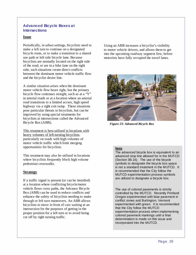
Advanced Bicycle Boxes at Intersections Issue Periodically, in urban settings, bicyclists need to make a left turn to continue on a designated bicycle route, or to make a transition to a shared use path or left side bicycle lane. Because bicyclists are normally located on the right side of the road, or are in a bike lane on the right side, such situations create direct conflicts between the dominant motor vehicle traffic flow and the bicyclist desire line. A similar situation arises when the dominant motor vehicle flow bears right, but the primary bicycle flow continues straight, such as at a “Y” in arterial roads or at a location where an arterial road transitions to a limited access, high speed highway via a right exit ramp. These situations pose particular threats to bicyclists, but can be improved by using special treatments for bicyclists at intersections called the Advanced Bicycle Box (ABB). This treatment is best utilized in locations with heavy volumes of left-turning bicyclists, particularly on roads with high volumes of motor vehicle traffic which limit merging opportunities for bicyclists. This treatment may also be utilized in locations where bicyclists frequently block high volume pedestrian crosswalks. Strategy If a traffic signal is present (or can be installed) at a location where conflicting bicycle/motor vehicle flows cross paths, the Advance Bicycle Box (ABB) can be used to reduce conflicts and enhance the safety of bicyclists needing to make through or left turn maneuvers. An ABB allows bicyclists to move in front of cars waiting at an intersection for the purposes of getting in the proper position for a left turn or to avoid being cut off by right turning traffic.
Using an ABB increases a bicyclist’s visibility to motor vehicle drivers, and allows them to get into the upcoming roadway segment first, before motorists have fully occupied the travel lanes.
Figure 23: Advanced Bicycle Box
Note The advanced bicycle box is equivalent to an advanced stop line allowed for in the MUTCD (Section 3B.16). The use of the bicycle symbols to designate the bicycle box space is not a standard treatment in the MUTCD. It is recommended that the City follow the MUTCD experimentation process symbols are utilized to designate a bicycle box. The use of colored pavements is strictly controlled by the MUTCD. Recently Portland Oregon experimented with blue pavement in conflict zones and Burlington, Vermont experimented with green. It is recommended that the City follow the MUTCD experimentation process when implementing colored pavement markings until a final determination is made on this issue and incorporated into the MUTCD.

Page 30
Advanced Bicycle Boxes at Intersections (Continued) An ABB is created by pulling the stop bar back from the crosswalk to create a 10-15 foot area between the stop bar and crosswalk where bicyclists can queue at the traffic light (see Figure 22). The ABB may be at the head of one, two or three travel lanes, which ever is appropriate to facilitate the necessary bicycle movements. Bicycle signal heads may be used in conjunction with an ABB to allow programming of an independent, advanced green phase for cyclists. A countdown signal can be added to alert bicyclists of the amount of time available to get into the ABB before the parallel traffic is given a green light. During a red signal phase, bicyclists are able to better position themselves for a left turn by moving left across the bike box. ABBs are most effective when a bicycle lane is present on the street. The geometric key is that there is sufficient space on the right for a bicyclist to safely make one’s way along a queue of vehicles stopped at the signal to the front of the line. Figure 24: Example Advanced Bicycle Box Layout
Note The signs shown for this treatment are a variation on the developed R10-6 and R10-6a, Stop Here on Red Signs. There are no standard MUTCD signs for use with an advanced bicycle box situations, so it is recommended that the City follow the MUTCD experimentation process when implementing new signs such as one shown in Figure 24.

Page 31
Optimized Use of Right-of-Way Width Issue Many urban streets in Baltimore have expansive right-of-way widths. In some instances this width is primarily in pavement and is used to serve only motor vehicles at high speeds and peak hour volumes. In some cases very wide sidewalks are provided. In other instances the right-of-way width is used for large lawn or tree planted medians. A variety of solutions may be available to re-allocate some of this right-of-way width to improve conditions for bicycling. Strategies The City can evaluate the corridors with expansive right-of-way widths and adopt standards and policies to guide the redesign of these roads when restriping, resurfacing, rehabilitation or reconstruction is undertaken.
Strategy One – On-Street Facilities: Following are strategies for gaining extra space that can be redistributed for bicycle use in the roadway as wide outside lanes, striped shoulders or bike lanes. Table 2 shows possible uses depending on the amount of extra width obtained: • On multi-lane roadways travel lanes can be
narrowed to 10 or 11 feet. • On streets with raised medians, the median
could be narrowed providing more pavement width.
• Road diets can be employed, if appropriate, to eliminate one or two travel lanes.
• If parking supply exceeds demand, parking can be consolidated and limited to one side of the street, or eliminated altogether if it is truly unnecessary.
Strategy Two – Off-Street Facilities: Following are strategies for converting extra off road right-of-way width for use by bicycles: • On roadways with generously wide
sidewalks, one-way sidewalk bicycling (8’ minimum width) can be implemented or a curb separated bike lane can be created between the right travel lane and sidewalk/tree buffer.
• Sometimes unique roadway configurations, topography and/or adjacent land uses create imbalanced traffic flow patterns and bicycle desire lines over relatively long distances. It may be safer and more effective to design different bicycle accommodations for each side of the road.
References American Association of State Highway and Transportation Officials. “Guide for the Development of Bicycle Facilities.” Washington, D.C.: AASHTO, 1999.
Table 2: Example Redistribution of Extra On-Street Width
Extra W idth Obta in ed
*Resultin g Outside Lane
Width Use of Ex tra W id th
5' or more 15' or more Install a dedicated bicyc le lane.
3' to 4' 13' to 14' Install a w ide outs ide lane the "Shared Lane" (Sharrow) pavement m ark ing, or a s triped shoulder.
2' 12' Install a w ide outs ide lane, with poss ible "S hared Lane" (S harrow) pavement mark ing.
1' 11' Make the outs ide lane wider than other lanes.
for B icyc le U se (One D irection of T rave l)
* Assum ing minim um beginning lane width of 10'
Example R ed is tribu tion o f Extra On-S treet Width
Note The designer is encouraged to utilize engineering judgment when developing retrofit solutions to accommodate bicyclists within the road environment and to follow the MUTCD experimentation process when traffic control strategies other than those currently in use in the MUTCD are utilized.

Page 32
U.S. Department of Transportation, Federal Highway Administration. “Manual on Uniform Traffic Control Devices.” Washington, D.C.: U.S. DOT, FHWA, 2003. Maryland Department of Transportation, State Highway Administration. “Standard Sign Book.” Baltimore, MD. Maryland Department of Transportation, State Highway Administration. “Maryland Supplement to the MUTCD,” Baltimore, MD. Expected in 2006. Maryland Department of Transportation, State Highway Administration. “Bicycle and Pedestrian Facility Design Guide,” Baltimore, MD. Expected in 2006. Virginia Department of Transportation. “Work Area Protection Manual.” Richmond, VA, 2005. City of San Francisco Department of Parking and Traffic “Bicycle Plan Update: Supplemental Design Guidelines,” San Francisco, CA, September, 2003. City of Chicago Department of Transportation, Bureau of Traffic “Bike Lane Design Guide.” Chicago, IL, 2002. Wisconsin Department of Transportation, “Wisconsin Bicycle Facility Design Handbook,” January 2004. Philadelphia Department of Transportation, “Philadelphia Bicycle Facility Design Guidelines,” 1999. District of Columbia Department of Transportation, Bicycle Facility Design Guide,” January 2006. US Department of Transportation (FHWA) and ITE “Traffic Calming: State of the Practice,” Reid Ewing, August 1999. Institute of Transportation Engineers, “Innovative Bicycle Treatments: and Informational Report,” May 2002.