
Introduction - City of Sherwood
53
Introduction Effects of Urbanization Urban development alters the hydrology of watersheds and streams by disrupting the natural water cycle. Impacts include: • Runoff volumes increase up to 50 percent over pre-developed volumes. • Peak runoff discharges increase two to five times pre-developed discharges. • Runoff velocities increase. • Time of concentrations decrease. • Frequency of bankfull and near bankfull events increase. • Flooding increases. • Dry weather flows (baseflow) decrease. These changes in the hydrology of the area translate into the changes shown in the typical hydrograph presented in Figure 1. 0 10 20 30 40 50 60 70 80 90 0 20 40 60 80 100 12 Time (min) Discharge (cfs) 0 Post Development Pre-development Figure 1. Effect of development on stormwater discharge rates. 27
Transcript of Introduction - City of Sherwood

Introduction Effects of Urbanization Urban development alters the hydrology of watersheds and streams by disrupting the natural water cycle. Impacts include:
• Runoff volumes increase up to 50 percent over pre-developed volumes. • Peak runoff discharges increase two to five times pre-developed discharges. • Runoff velocities increase. • Time of concentrations decrease. • Frequency of bankfull and near bankfull events increase. • Flooding increases. • Dry weather flows (baseflow) decrease.
These changes in the hydrology of the area translate into the changes shown in the typical hydrograph presented in Figure 1.
0102030405060708090
0 20 40 60 80 100 12
Time (min)
Dis
char
ge (c
fs)
0
Post Development
Pre-development
Figure 1. Effect of development on stormwater discharge rates.
27

Sources of Pollutants Urbanization increases the amount of sediment, nutrients, microbes, organic matter, toxic pollutants, and trash in stormwater flows. Sediment in water (suspended solids, dissolved solids, and/or turbidity) is the cause of:
• Filling of lakes and reservoirs • Stream turbidity • Habitat changes • Recreation/aesthetic loss • Transport of other contaminants
Nutrients in water (nitrate, nitrite, ammonia, organic nitrogen, phosphate, and total phosphorus) are the cause of:
• Algae blooms • Eutrophication • Ammonia Toxicity to aquatic life • Nitrate Toxicity
Microbes in water (Total and Fecal Coliform, Fecal Streptococci, Viruses, E.Coli, Enteroccus) can be the cause of:
• Gastrointestinal diseases • Ear/Intestinal infections • Shellfish bed closure
Organic Matter (vegetation, septic tank overflows, pet waste) in water is the cause of:
• Dissolved oxygen depletion • Odors • Fish kills
Toxic Pollutants (heavy metals such as cadmium, copper, lead, zinc, organics, hydrocarbons, pesticides/herbicides) can be the cause of:
• Human & aquatic toxicity • Bioaccumulation in the food chain • Thermal Pollution Dissolved oxygen depletion • Habitat changes
Trash and debris cause:
• Recreation loss • Aesthetic loss
28

Construction BMPs An Ounce of Prevention is Worth a Pound of Cure Construction BMPs fall into two categories, erosion control and sediment control. Erosion control is the protection of the soil surface from the impact of rain drops and the resulting detachment of soil particles. Sediment control are the practices that capture soil particles that have been detached and transported down slope. It is far more efficient and cost effective to prevent erosion than to capture sediment.
Design Methodology and BMP Selection Criteria Construction BMPs are typically designed for erosion control, sediment control, or control of wastes (hazardous, solid, etc.). For the best results, BMPs should be used in series with one or more BMPs. The operator of the construction site should concentrate efforts on erosion control; but, provide sediment control backup BMPs. A listing of construction erosion and sediment control BMPs and the benefits each provides is Shown in Table 1. Further information on each BMP is presented in the following sections of this chapter.
Table 1. Construction BMP characteristics chart
Flow Runoff Nutrientatten- volume Erosion Sediment loading Organic
Construction BMP uation reduction Control control (N,P) loadingMinimize Clearing & CompactionConstruction SequencingConstruction EntranceInterceptor Swale & DikeSlope DrainEnergy Dissipation - Riprap ApronSoil RougheningChemical StabilizationMulchErosion Control MatsVegetationEmbedded Silt FenceInlet ProtectionSediment TrapCheck Dams
- Primary benefit - Secondary benefit - Little or no benefit
Quantity Quality
29

Construction Planning
Minimize Clearing and Compaction Description Clearing of natural vegetation and vehicular traffic on the site will expose and compact soils causing erosion and greater amounts of runoff. Minimization of Clearing and Compaction will decrease the amount of soil exposed to erosion and will decrease the amount runoff from due to compacted soil.
Applicability Existing vegetation can often be incorporated into the design and construction of a development lessening the amount of bare soil exposed to rain and wind. Compacted soil does not allow for adequate infiltration of precipitation, therefore increasing runoff quantities and flowrates. Increased flowrates increase erosion and sediment transport.
Design Criteria Landscaping and clearing requirements vary from project to project. Vehicular traffic within the construction site should be limited and confined to areas that are protected with adequate sediment control practices.
Limitations Some native plants and grasses are not considered appropriate for developed sites; so, non-native grasses and plants would need to be planted.
Maintenance Requirements Maintenance of protective fencing as needed.
30

Construction Sequencing Description Exposing soil before required for construction can expose the soil to erosion for an extended period. Construction Sequencing coordinates land disturbing activities with construction requirements to minimize the amount of soil exposed to erosion at any time.
Applicability Only land needed for building activities and vehicular traffic should be cleared. Projects on larger sites and on projects that land disturbing activities can be phased are best suited for Construction Sequencing.
Design Criteria Areas of the site to be preserved should be clearly marked on the plans and delineated on the site. The timing of clearing and access to different areas of the site should be indicated in the contract documents.
Limitations Sometimes, smaller projects do not lend themselves to sequencing of land disturbing activities.
Maintenance Requirements Maintenance of protective fencing as needed.
31

Runoff and Run-on Control BMPs
Construction Entrances Description Mud and sediment carried off-site on the tires of equipment and vehicles will be deposited on the neighboring streets. This sediment will end up in the local streams if not swept up. Construction Entrances are systems that clean vehicles of mud, sediment, and aggregate prior to leaving the site.
Applicability Any entrance/exit of a construction site.
Design Criteria A six inch layer of washed gravel or round stone (greater than 1 inch) can be used to stabilize construction site entrances. The stabilized entrance should be at least 50 feet long. The entrance should be as long as the longest vehicle that will enter the site. If larger volumes of traffic are expected, a two-lane entrance is appropriate. Other methods of removing mud from vehicles are wheel wash facilities (dunk or mechanical) and rubble strips (cattle guard, logs, etc.). A dunk wheel wash is a water filled, stabilized (1 inch or greater gravel or stone) pit. The water depth should be at least two feet deep and the pit should be at least 20 foot long. The pit should be two vehicle lengths from the construction site exit and the entrance and exit to the pit should be stabilized.
Limitations In order to avoid puncturing tires, stabilized entrances should not be constructed with sharp edge stones.
Maintenance Requirements Stabilized entrances require periodic cleaning or addition of stone as the voids in the stones fill with mud and sediment. Wheel wash facilities and rubble strips will need to be cleaned as the pits fill in order to provide more room to store new mud and sediment. The street in front of the entrance should be cleaned as required to remove sediment that has been tracked off site.
32
Interceptor Swale & Dike Description Water running onto the site will increase erosion and be a nuisance to construction activities. Additionally, runoff from the construction site can have excessive amounts of sediment that can end up in local streams. Interceptor Swales and Dikes are diversion systems used to divert runoff around a site or to direct runoff from a site to a pond in order to settle out sediment prior to discharge from the site.
Applicability Any area that that is subject to runoff from up hill drainage areas.
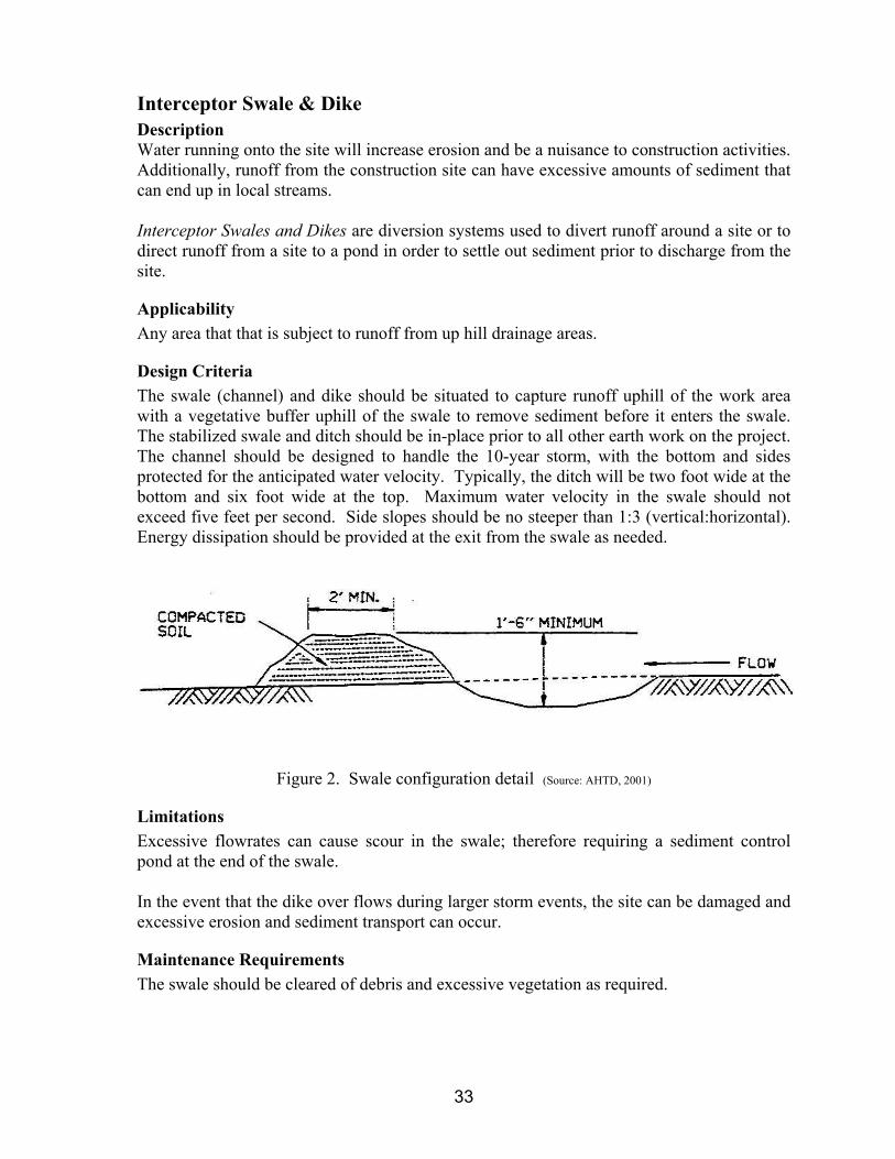
Design Criteria The swale (channel) and dike should be situated to capture runoff uphill of the work area with a vegetative buffer uphill of the swale to remove sediment before it enters the swale. The stabilized swale and ditch should be in-place prior to all other earth work on the project. The channel should be designed to handle the 10-year storm, with the bottom and sides protected for the anticipated water velocity. Typically, the ditch will be two foot wide at the bottom and six foot wide at the top. Maximum water velocity in the swale should not exceed five feet per second. Side slopes should be no steeper than 1:3 (vertical:horizontal). Energy dissipation should be provided at the exit from the swale as needed.
Figure 2. Swale configuration detail (Source: AHTD, 2001)
Limitations Excessive flowrates can cause scour in the swale; therefore requiring a sediment control pond at the end of the swale. In the event that the dike over flows during larger storm events, the site can be damaged and excessive erosion and sediment transport can occur.
Maintenance Requirements The swale should be cleared of debris and excessive vegetation as required.
33
Slope Drain Description Gullying and excessive erosion will take place on slopes subjected to concentrated flows of runoff. Slope Drains are conduits (open or closed) used to direct water down a slope while protecting the slope from erosion.
Applicability Slopes with the potential for intended or unintended concentrated flows
Design Criteria Slope drains (rundowns, pipe slope drains, etc.) should be placed where runoff from uphill drainage areas will concentrate. Slope drains should be sized to handle a 10 year storm from an area no greater than five acres. Minimum size for a pipe slope drain is 12 inch diameter. Slope rundowns (stone or riprap lined channels) should be constructed with the middle sufficiently lower than the sides to ensure flow stays in the rundown. Slope drains operate best when used in conjunction with interceptor swales and dikes on the top of the slope. Appropriate energy protection should be placed at the outlet of the pipe.
Limitations For larger storms, the slope drain may not operate properly and can cause excessive gullying and slope erosion as well as damage to the construction site. Slope drains that are improperly designed or constructed such that the flow does not stay in the drain will cause excessive erosion.
Maintenance Requirements Slope drains should be inspected weekly and kept clear of trash, debris, and vegetation.
34
Energy Dissipation – Riprap Aprons Description Water exiting a channel, swale, pipe, or culvert (any water carrying conduit) typically is in a concentrated stream with a relatively high velocity. This high energy stream of water erodes unprotected soil. Energy Dissipation is a structural BMP placed at the exit of a water carrying conduit to slow the velocity and decrease the turbulence of the water. Permanent energy dissipation controls can be used during the construction phase of the project, and should be designed according to methods described in the Residential and Commercial BMPs section of this manual.
Applicability All channels or pipes carrying runoff at velocities that will erode the soil in the discharge area.
Design Criteria Determine the required median size (d50) of riprap using graph in Figure 3 below. Enter the graph on the X-axis with the discharge in cubic feet per second, move vertically to intersect either the appropriate depth of flow (d) line or the velocity of flow (v) line, then read to the horizontally to Y-axis on the right side to determine the required median diameter of riprap (d50). Determine the minimum required apron length using the graph in Figure 3. Enter the graph on the X-axis with the discharge in cubic feet per second, move vertically to the second set of lines to intersect the appropriate depth of flow (d), then read horizontally to the left to determine the minimum required length of apron (La) in feet.
Limitations Riprap aprons are best suited for applications where the Froude Number at the conduit exit is less than 2.5. Some Communities do not allow riprap as a permanent control method of energy dissipation.
Maintenance Requirements The apron should be inspected after large storms to ensure that the riprap is in place. riprap should be replaced when it is dislodged or missing.
35

Figure 3. Riprap apron sizing. (SCS, 1975)
36

Figure 4. Riprap apron detail (Source: MESCG, 1996)
37

Erosion Control BMPs
Soil Roughening
Description Water flowing down a bare slope will erode soil and transport soil to the bottom of the slope. Soil roughening is the practice of increasing the roughness of exposed soil by making grooves, tracks, or terraces (stair-steps) which run perpendicular to the flow path (parallel to slope) slowing flow and trapping sediment.
Applications Soil roughening can be used on a wide variety of slopes and in conjunction with seeding and mulching.
Design Criteria Tracking with lugged tracked equipment is appropriate on sandy material so as to not excessively compact the soil. Grooving can be accomplished using a plow with the furrows three inches deep and less than 15 inches apart. Terraced (stair-stepping) slopes should have the vertical cuts no more than two feet deep and the horizontal steps should be wider than the depth of the vertical cut. The horizontal step should slope backward to the vertical cut upslope on the hill. The slope should be seeded immediately after roughening and mulch or chemical stabilization should be utilized where appropriate.
Limitations Soil roughening should not be used on rocky soils or soils that are high in clay content. Tracking may cause excessive compaction which can lead to greater erosion
Maintenance Requirements Roughened slopes should be inspected after ½ inch and greater storms and problem areas noted. After a rain event, slopes may need reconstruction, re-roughening, reseeding, and remulching.
38

Chemical Stabilization Description Erosion is caused by rainfall impact detaching soil particles and runoff carrying the particles downslope. Chemical stabilization is the practice of spraying chemicals (tackifiers, soil binders) on the soil to hold the soil particles in place and protect against erosion.
Applicability Areas that have been cleared of vegetation or do not have a protective cover on the soil. If temporary seeding can not be used or would not be effective due to the time of year, steepness of slope, or other reasons, chemical stabilizers can be applied to protect against erosion. Chemical stabilization can be used in conjunction with seeding and mulching.
Design Criteria The type of chemical used (asphalt emulsion, polyacrylamides (PAM), vinyl, or rubber), the application rate, and application method should meet the manufactures recommendations.
Limitations Improper application methods or rates can result in over application which can diminish infiltration and cause additional runoff.
Maintenance Requirements Chemically stabilized areas should be inspected regularly and after ½ inch or greater rainfalls and stabilizer reapplied as required.
39
Mulch Description Erosion is caused by rainfall impact detaching soil particles and runoff carrying the particles downslope. Mulch can be applied to the area to hold the soil particles in place and protect against erosion. Mulching is the practice of applying a layer of organic material (hay, straw, wood fiber, paper fiber, etc.) to protect the soil from impact of precipitation.
Applicability Areas that have been cleared of vegetation or do not have a protective cover on the soil. Mulches are typically used to protect areas that have been seeded. Mulching can be used in conjunction with chemical stabilization.
Design Criteria Straw mulch should be evenly applied at a rate of 2 tons of dry straw per acre. The mulch should be crimped into the soil immediately after application. Mulch should not be applied in areas with concentrated flows or on steep slopes. Mulch is typically applied using a mulch blower; but, can be applied by hand in small or hard to reach areas.
Limitations Wind and concentrated water flows can blow or wash mulch from the application area.
Maintenance Requirements Mulched areas should be inspected regularly and after ½ inch or greater rainfalls and mulch reapplied as required.
40

Erosion Control Mats Description Erosion is caused by rainfall impact detaching soil particles and runoff carrying the particles downslope. Erosion Control Mats can be applied to the area to hold the soil particles in place and protect against erosion. Erosion Control Mats are manufactured blankets of netting with organic filler or geosynthetic material used to protect the soil from impact of precipitation.
Applicability Areas that have been cleared of vegetation or do not have a protective cover on the soil. Erosion Control Mats are typically used to protect short steep slopes or in areas of concentrated water flows.
Design Criteria There are many different types of erosion control mats and each is made for different situations (slope, duration of protection, amount of protection, soil, degradability of mat, etc.); therefore, the type of erosion control mat used and the installation methods should meet the manufactures recommendations.
Limitations If not properly installed (anchored to the ground and overlapped on the edges), erosion control mats can be washed downslope.
Maintenance Requirements Areas with erosion control mats should be inspected regularly and after ½ inch or greater rainfalls and problem areas corrected as required.
41
Vegetation Description Erosion is caused by rainfall impact detaching soil particles and runoff carrying the particles downslope. Vegetation (seeded or sodded) can hold the soil particles in place and protect against erosion.
Applicability Any area of a construction site that the natural vegetation has been removed. Seeding or sodding can be used as a temporary or a final erosion control measure. A substantial savings can be realized by completing the earth work for an area and implementing final vegetative stabilization.
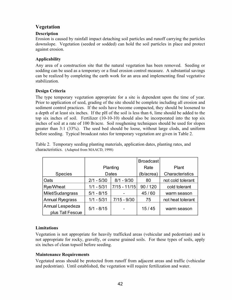
Design Criteria The type temporary vegetation appropriate for a site is dependent upon the time of year. Prior to application of seed, grading of the site should be complete including all erosion and sediment control practices. If the soils have become compacted, they should be loosened to a depth of at least six inches. If the pH of the soil is less than 6, lime should be added to the top six inches of soil. Fertilizer (10-10-10) should also be incorporated into the top six inches of soil at a rate of 100 lb/acre. Soil roughening techniques should be used for slopes greater than 3:1 (33%). The seed bed should be loose, without large clods, and uniform before seeding. Typical broadcast rates for temporary vegetation are given in Table 2. Table 2. Temporary seeding planting materials, application dates, planting rates, and characteristics. (Adapted from MAACD, 1998)
BroadcastRate Plant
Species (lb/acrea) CharacteristicsOats 2/1 - 5/30 8/1 - 9/30 80 not cold tolerantRye/Wheat 1/1 - 5/31 7/15 - 11/15 90 / 120 cold tolerantMilet/Sudangrass 5/1 - 8/15 - 45 / 60 warm seasonAnnual Ryegrass 1/1 - 5/31 7/15 - 9/30 75 not heat tolerantAnnual Lespedeza plus Tall Fescue
15 / 45- warm season
DatesPlanting
5/1 - 8/15
Limitations Vegetation is not appropriate for heavily trafficked areas (vehicular and pedestrian) and is not appropriate for rocky, gravelly, or course grained soils. For these types of soils, apply six inches of clean topsoil before seeding.
Maintenance Requirements Vegetated areas should be protected from runoff from adjacent areas and traffic (vehicular and pedestrian). Until established, the vegetation will require fertilization and water.
42

Sediment Control BMPs
Embedded Silt Fence
Description Water flowing in sheet or shallow flow will carry sediment down a slope and off-site. Embedded Silt Fence (ESF) is a barrier made of geotextile fabric placed along a contour to capture water, slow the flowrate, trap sediment, and allow water to filter through the fabric.
Applications Small drainage areas with sheet flow or shallow flow.
Design Criteria Embedded Silt Fence (ESF) should be placed on a contour and designed to hold runoff from the 10 year storm from an area of 100 sq. ft for each foot of fence. The maximum depth of retained water on the upstream side of the fence should be two feet. The maximum slope length above the fence should be no more than 100 feet. The maximum slope above the fence is 1:1. The fabric shall be buried in a trench that is at least eight inch deep and eight inches wide as shown below. The fabric shall be place on the upstream side of the posts. Post shall be made of metal (T-post) or wood (2”x2”) and placed no more than six feet apart.
Figure 5. Embedded Silt Fence (Source: AHTD, 2001)
43

Limitations Silt fence must be embedded or it will not function properly and should not be installed in rocky soil where it cannot be properly embedded. Silt fence is not designed to hold back concentrated flow and therefore should not be placed across channels, gullies, or streams. Silt fence should not be run down slopes as it will concentrate flow causing gully erosion and causing downstream BMPs to fail. Silt fence should not be placed at the top of slopes as it will not provide any sediment control but will increase costs.
Maintenance Requirements ESF should be inspected weekly and after ½ inch or greater rainfalls for proper installation, defective fencing, erosion on the ends, and excessive sediment buildup behind the fence (half the fence height).
44

Inlet Protection
Description Runoff from a construction site often carries sediment into the stormwater sewer system, which discharges into local streams. Besides the problems caused by sediment, other pollutants (e.g. oil, grease, and nutrients) are often attached to the sediment. Inlet Protection is the practice of placing gravel, sand bags, or silt fence around an inlet to allow runoff to pond and sediment to settle out prior to entering the stormwater sewer system.
Applications Any storm drain inlet that could receive runoff from the construction site.
Design Criteria For inlets that are not in paved areas, a detention pond should be excavated around the inlet that is at least one foot deep (below the inlet crest) and that has a detention volume of at least 35 yd3 per disturbed acre of watershed. The pond should start at the toe of the dam material; so, if gravel or sandbags are to be used the pond will be at least three feet from the inlet, whereas if silt fence is used, the pond can start at the edge of the inlet. The side slopes of the detention pond should be no greater than 2:1. If silt fence is used as the dam material, the post should be driven at the edge of the inlet and should be no greater than three feet apart. The fence should be installed according to the detail in Figure 6. For inlets in paved areas, either gravel or sandbags should be used as the dam material. If gravel is to be used as the dam material, the gravel should be at least 1” in diameter. The dam should be no higher than one foot high and the side should have no greater than a 2:1 (horizontal:vertical) slope. If sandbags are used as the dam material, the bags shall be no heavier than 50 lbs and shall be stacked no higher than three bag diameters high, with the bags layered in a pyramid formation.
Limitations Inlet protection control measures are not capable of handling large quantities of sediment and can require maintenance during rain events in order to protect nearby facilities and to eliminate flooding. Ponding can cause flooding problems for surrounding facilities.
Maintenance Requirements Inlet protection measures should be inspected during storm events to ensure surrounding facilities are not flooded. Inlet protection measures should be inspected weekly and after ½ inch or greater rainfalls for proper installation, defective fencing, erosion, and excessive sediment buildup and defective measures repaired or replaced within 24 hours. .
45

Figure 6. Silt fence inlet protection detail (Source: AHTD, 2001)
46

Sediment Trap
Description Water carrying sediment off-site can cause damage to neighboring property and local streams. Sediment Traps provide an area for sediment to settle out of the runoff prior to discharge from the site.
Applications Sediment traps are well suited for sites that will be required to have a permanent stormwater control basin; but, should be used for any concentrated flow (culvert, pipe, swale, etc.) that could have sediment in the runoff leaving the site.
Design Criteria The removal efficiency of Sediment Traps is a function of the total surface area of the pond, the shape of the pond, the influent flow rate, and the type of soil in the runoff. The maximum drainage area for a Sediment Trap shall be 3 acres, for larger areas a Sediment Basin shall be used. Trap minimum bottom area and spillway width are given in Table 3. The berm or levee will curving upstream to hold the water, the berm will have 3:1 side slopes (maximum) and have a maximum depth of three feet. The outlet spillway shall be made of six inches of stone (6 inch diameter minimum) and be placed on a geotextile fabric.
Table 3 Minimum sediment trap dimensions
TrapWater Width
Drainage Bottom OverflowArea Area Spillway
(acres) (sq ft) (ft)
1 or less 250 6
1 to 2 675 12
2 to 3 1500 18
Limitations Sediment Traps do not have sufficient surface area to allow for settling of very small particles (e.g. clay, silt). Sediment Traps are not appropriate for runoff from areas greater than three acres.
47

Maintenance Requirements Sediment Traps should be inspected weekly and after ½ inch or greater rainfalls for proper installation, erosion, and excessive sediment buildup and defective measures repaired or replaced within 24 hours.
Figure 7 Sediment trap detail (Adapted from: AHTD, 2001)
48

Check Dams
Description Excessive velocity of water in swales or channels causes erosion and transports the sediment downstream to local streams. Check Dams (ditch check) slow water in channels and provide an area for sediment to settle out of the water before it flows over the dam.
Applications Any unlined channel or any channel that the vegetative protection has not developed. Steeper slopes are more subject to erosion than flatter slopes.
Design Criteria Place ditch checks such that the top of the downstream check is at the same elevation as the bottom of the next upstream check. Checks must constructed such that the top elevation of the center of the check is at least six inches below the bottom elevation of both ends of the check. The dam must be excavated into the channel no less than six inches as shown in Figures 8, 9, and 10.
Limitations If improperly constructed, water will flow around or through the check dam and erode the banks of the channel. Large flows (less frequent storms) can washout the check dams, erode the banks at the end of the check dams, or cause excessive scour at the outfall of the check dam.
Maintenance Requirements Check Dams should be inspected weekly and after ½ inch or greater rainfalls for proper installation, erosion, and excessive sediment buildup and defectives should be repaired or replaced within 24 hours.
49

Figure 8 Baled straw check dam detail. (Source: AHTD, 2001)
50

Figure 9 Sand bag check dam detail. (Source: AHTD, 2001)
51
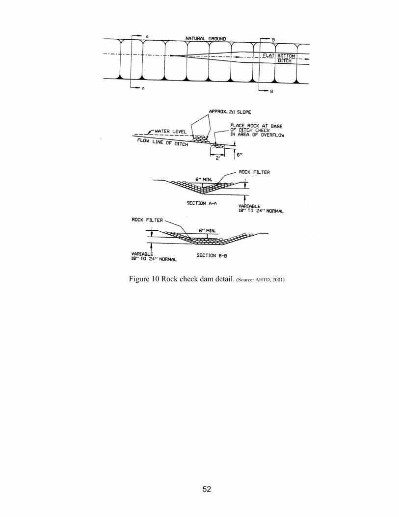
Figure 10 Rock check dam detail. (Source: AHTD, 2001)
52

Solid Waste Management
Description Solid wastes that are improperly disposed of, can be blow or washed from construction sites causing others to pickup the wastes from their property. Solid Waste Management refers to the proper handling and disposal of all construction wastes.
Applications All construction sites
Criteria Trash and waste construction materials should be picked up daily and properly disposed of.
Limitations None
Maintenance Requirements Daily pickup of trash and construction waste materials.
53

Hazardous Waste Management
Description Hazardous wastes can be washed or accidentally dumped into the storm water system causing serious pollution of local streams. Hazardous Waste Management is the proper handling, storage, use, and disposal of material listed as hazardous by EPA and/or ADEQ
Applications All materials listed as hazardous by EPA and/or ADEQ.
Criteria Guidelines published by EPA and OSHA for the types of materials to be used on the construction site should be incorporated into the SWPPP. The types of materials that are generally considered hazardous are:
• Fuels (diesel, gas, etc.) • Oils and greases (lubricating, cutting, etc.) • Petroleum based materials (asphalt, emulsions, solvents) • Paints (including wood preservatives, stains, and lead based) • Solvents (paint thinners, cleaners, etc.) • Pesticides, herbicides, insecticides
Proper management of hazardous materials entails:
• Replace hazardous materials with a non-hazardous materials • Minimize the use of hazardous materials • Reuse and recycle hazardous materials • Proper use of hazardous materials • Proper storage and handling of hazardous materials • Proper disposal of hazardous materials
Employees must be trained in the use, storage, and disposal of hazardous wastes. Hazardous materials should be stored so only authorized personnel can use the material. The following methods should be followed for spill prevention and clean-up:
• The manufacturers recommended methods for spill clean-up should be clearly posted and personnel should be trained in the location of clean-up supplies and clean-up procedures.
• Clean-up supplies should be kept in a secure on site. • Personnel should wear proper protective clothing when cleaning up the spill. • Spills should be cleaned up immediately and the waste properly disposed of. • Licensed hazardous waste haulers must be used to transport hazardous wastes to
approved treatment and disposal sites.
54

Concrete Waste Management
Description Concrete waste from washout of ready mix trucks, concrete pumps, and other concrete equipment causes chemical and changes in runoff by increasing sediment and changing the pH. Concrete Waste Management is the practice of capturing all concrete wastes to allow
Applications All construction sites with concrete work.
Design Criteria Provide a minimum of six cubic feet of containment volume for every 10 cubic yards of concrete to be poured.
Limitations Improperly sized washout area can overflow and washout will not be contained.
Maintenance Requirements The washout pit should be cleaned weekly and the waste material properly disposed of.
55

Residential and Commercial BMPs Introduction Historically, stormwater management policies were developed to mitigate the impact of land development in terms of the quantity of water released; therefore, systems were sized to reduce the post-development peak discharge rates to the pre-development rates. But, storm water systems sized to reduce peak discharge are not effective at removal of pollutants; therefore, the design of storm water systems must now incorporate methods for improving water quality. The table below gives an overview of the capabilities of the BMPs discussed in this manual.
Table XX Post development BMP characteristics chart
Flow Runoff Nutrientatten- volume Sediment loading Organic Metals Bacteria
Construction BMP uation reduction control (N,P) loading loading loadingDry BasinWet BasinGrass Filter StripInlet Floatables InterceptorOil-Sediment SeparatorInfiltration TrenchPorous PavementUnderground Detention Vault
- Primary benefit - Secondary benefit - Little or no benefit
Quantity Quality
56

Dry Basin
Description Increased flowrates due to development cause increased erosion and increased stream bank erosion. In addition, runoff leaving as developed site it will carry sediment and attached pollutants. A Dry Basin is a surface storage structure designed to provide water quantity control through decrease and attenuation runoff peaks and by providing an area for sedimentation to remove sediment and attached pollutants.
Application Dry Basins are applicable for large drainage areas and should used in conjunction with a water quality control structure. In addition, the basin can be used for recreational and other open space opportunities between storm runoff events.
Design Criteria The maximum contributing drainage area to be served by a Dry Basin is 75 acres. Dry Basins should be sized to temporarily store the volume of runoff required to reduce the post-development peak flow of the 5 year, 10 year, 25-year, and 50 year storm events to the pre-development rates, and control the 100-year storm if required. The basin should an elongated and irregular shape with a length to width ratio of 2:1; but, 3:1 is preferred. Routing calculations must be used to demonstrate that the storage volume is adequate. A detail of a Dry Basin is shown below. Embankments shall be less than eight feet in height and shall have side slopes no steeper than 3:1 (horizontal to vertical). Geotechnical slope stability analysis is recommended for embankments greater than four feet in height. The bottom area of storage facilities should be graded toward the outlet to prevent standing water conditions. A low flow or pilot channel across the facility bottom from the inlet to the outlet is recommended to convey low flows and prevent standing water conditions. Adequate maintenance access must be provided for all basins. Inlet Inflow channels are to be stabilized with flared riprap aprons, or the equivalent. A sediment forebay sized to 0.1 inches per impervious acre of contributing drainage should be provided.. Seepage control or anti-seep collars should be provided for all outlet pipes. Riprap, plunge pools or pads, or other energy dissipators are to be placed at the end of the outlet to prevent scouring and erosion. If the basin discharges to a channel with dry weather flow, care should be taken to minimize tree clearing along the downstream channel, and to reestablish a forested riparian zone in the shortest possible distance.
57

An emergency spillway is to be included in the stormwater pond design to safely pass the extreme flood flow. The spillway prevents pond water levels from overtopping the embankment and causing structural damage. The emergency spillway must be designed and located so that downstream structures will not be impacted by spillway discharges. A minimum of 1 foot of freeboard must be provided, measured from the top of the water surface elevation for the extreme flood, to the lowest point of the dam embankment not counting the emergency spillway. In the event that further reduced peak flowrates are required to protect the downstream channel, a dry extended detention basin can be utilized. Dry Extended Detention Basins should be equipped with a low flow orifice capable of releasing the channel protection volume over 24 hours must. The channel protection orifice should have a minimum diameter of 3 inches and should be adequately protected from clogging by an acceptable external trash rack. A detail of a Dry Extended Detention Basin is shown below.
Limitations Dry Basins are only moderately effective at removing suspended pollutants (sediment and attached pollutants, nutrients and metals) and are ineffective at removing dissolved pollutants. During some periods of the year, dry ponds can be a breeding site for mosquitoes.
Maintenance Dry Ponds require inspection and maintenance as shown below.
• Bi-weekly or as needed, mow and tend to grass around pond. • Monthly or more frequently if required, remove trash and debris from pond, outlet
structure, and surrounding area. • Annually, inspect embankments, outlets, and spillways for damage and maintain as
required. • Annually, inspect for sediment buildup and remove buildup as required. • Annually, remove any invasive vegetation.
58

Figure 11 Dry detention basin detail. (Source: GSWMM, 2001)
59

Figure 12 Extended dry detention basin detail (Source: GSWMM, 2001)
60

Wet Basin
Description Increased flowrates due to development cause increased erosion and increased stream bank erosion. In addition, runoff leaving as developed site it will carry sediment and attached pollutants. Wet Ponds (retention ponds, wet extended detention ponds) are constructed to provide a permanent pool of water during the wet season or year-round. The pond provides for peak discharge attenuation and pollutant removal. Pollutants are removed from stormwater by settling and biological uptake.
Applicability Wet ponds can be designed to enhance the landscaping and provide an attractive addition to a development. To maintain a permanent pool, wet ponds typically require about a minimum drainage area of 25 acres. Maintenance needs, dissolved oxygen requirements, and safety concerns should be addressed during design.
Design Criteria The maximum contributing drainage area to be served by a Wet Basin is 75 acres and the minimum is 25 acres. The active pool of the Wet Basins should be sized to temporarily store the volume of runoff required to reduce the post-development peak flow of the 5 year, 10 year, 25-year, and 50 year storm events to the pre-development rates, and control the 100-year storm if required. The basin should an elongated and irregular shape with a length to width ratio of 2:1; but, 3:1 is preferred. Routing calculations must be used to demonstrate that the storage volume is adequate. A detail of a Wet Basin is shown in Figure 13 and a typical cross section of a Wet Basin is shown in Figure 14. The designer must conduct a water balance to ensure that sufficient inflow is available to maintain the permanent pool. The permanent pool should be at least four feet deep is discourage growth of aquatic plants. Embankments shall be less than eight feet in height and shall have side slopes no steeper than 3:1 (horizontal to vertical). Geotechnical slope stability analysis is recommended for embankments greater than four feet in height. Adequate maintenance access must be provided for all basins. Inlet Inflow channels are to be stabilized with flared riprap aprons, or the equivalent. A sediment forebay sized to 0.1 inches per impervious acre of contributing drainage should be provided. Seepage control or anti-seep collars should be provided for all outlet pipes. Riprap, plunge pools or pads, or other energy dissipators are to be placed at the end of the outlet to prevent scouring and erosion. If the basin discharges to a channel with dry weather flow, care should be taken to minimize tree clearing along the downstream channel, and to reestablish a forested riparian zone in the shortest possible distance.
61
An emergency spillway is to be included in the stormwater pond design to safely pass the extreme flood flow. The spillway prevents pond water levels from overtopping the embankment and causing structural damage. The emergency spillway must be designed and located so that downstream structures will not be impacted by spillway discharges. A minimum of 1 foot of freeboard must be provided, measured from the top of the water surface elevation for the extreme flood, to the lowest point of the dam embankment not counting the emergency spillway.
Limitations Depending on the location, Wet Ponds can require maintenance to remove trash and overgrowth. In developments with excess nutrients (nitrogen and phosphorus in particular) due to over fertilization, wet ponds can require mechanisms (fountains, bubblers) to input oxygen. In some developments a permanent pool of water can be viewed as a safety concern.
Inspection and Maintenance Wet Ponds should be inspected and maintained according to the following schedule
• Bi-weekly or as needed, mow and tend to grass around pond. • Monthly or more frequently if required, remove trash and debris from pond, outlet
structure, and surrounding area. • Annually, inspect embankments, outlets, and spillways for damage and maintain as
required. • Annually, inspect for sediment buildup in forebay and wet pool, remove buildup if
required. • Annually, harvest wetland vegetation (if used) and remove any invasive vegetation.
62

Figure 13 Wet pond detail. (Source: Center of Water Shed Protection)
63
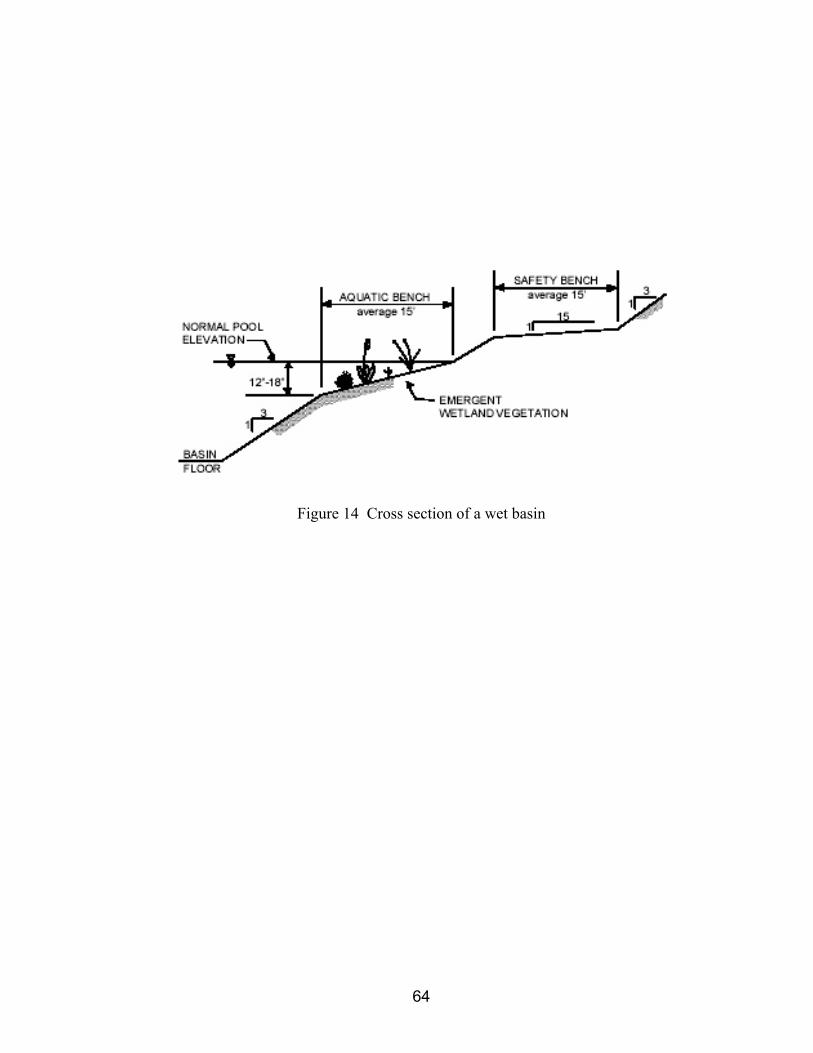
Figure 14 Cross section of a wet basin
64

Vegetated Swales and Strips Description Vegetated Swales (grass lined swales, biofilters, grassed channels) combine a channel, storage, and vegetation. The channel is used to move stormwater from one place to another; but, the channel is designed to provide some stormwater storage. The swale is designed to allow ponding (backwater) in the channel to enhance infiltration and pollutant removal. The vegetation provides increased pollutant (sediment, nutrients, metals) removal.
Selection Criteria Swales are best suited for sites with long narrow areas available for stormwater handling and storage. Swales are also well suited for areas that generate highly contaminated runoff such as filling stations. Generally swales are appropriate for drainage areas of five acres or less and should be constructed on flat slopes (1 to 2 percent). The bottom of the swale should be two feet above the seasonally high water table.
Design and Sizing Swales function best if the stormwater moves through the channel slowly and they are designed to maximize the channel surface area wetted by the flow. A swale should be designed such that a 1 inch storm will take 10 minutes to travel down the swale and should be designed as shown in the detail below. Swales should be designed as trapezoidal or parabolic channels with longitudinal slopes of 1 to 2 percent and side slopes no greater than 4:1 (25 percent). The channel bottom should be 2 to 8 feet wide. The swale should have dense vegetative cover that should be able to withstand the velocities induced by larger storms (25 year storm).
Limitations Pollutant removal capabilities are substantially decreased for swales in highly impermeable soils, for swales constructed on steep slopes, and for swales handling runoff from too large of drainage areas.
Inspection and Maintenance Swales should be inspected and maintained as indicated below.
• Bi-weekly or as needed, keep grass at a height of 3 to 4 inches. • Monthly or more frequently if required, remove trash and debris, outlet structure, and
surrounding area. • Annually, inspect embankments and outlets for damage and maintain as required. • Annually, inspect for sediment buildup and remove buildup when required.
65

Figure 15 Grass swale detail. (Source: GSWMM, 2001)
66
Grass Filter Strip
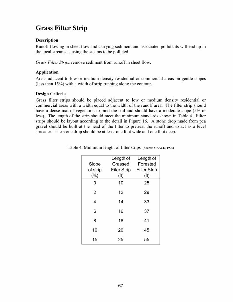
Description Runoff flowing in sheet flow and carrying sediment and associated pollutants will end up in the local streams causing the steams to be polluted. Grass Filter Strips remove sediment from runoff in sheet flow.
Application Areas adjacent to low or medium density residential or commercial areas on gentle slopes (less than 15%) with a width of strip running along the contour.
Design Criteria Grass filter strips should be placed adjacent to low or medium density residential or commercial areas with a width equal to the width of the runoff area. The filter strip should have a dense mat of vegetation to bind the soil and should have a moderate slope (5% or less). The length of the strip should meet the minimum standards shown in Table 4. Filter strips should be layout according to the detail in Figure 16. A stone drop made from pea gravel should be built at the head of the filter to pretreat the runoff and to act as a level spreader. The stone drop should be at least one foot wide and one foot deep.
Table 4 Minimum length of filter strips (Source: MAACD, 1995)
Length of Length ofSlope Grassed Forestedof strip Fiter Strip Filter Strip
(%) (ft) (ft)0 10 25
2 12 29
4 14 33
6 16 37
8 18 41
10 20 45
15 25 55
67

Figure 16 Filter strip detail. (Source: GSWMM, 2001)
Limitations If not planned properly, the land requirements of filter strips can be a problem in some developments. If the filter strip does not have a uniform grade, runoff will concentrate and could cause erosion in the filter strip.
Inspection and Maintenance Filter strips should be inspected periodically to ensure that the filter strip is working properly and that no erosion is taking place. The strip should be mowed to height of 4 to 6 inches as required.
68

Inlet Floatables Interceptor
Description Trash, debris, and lawn wastes are picked up by storm water and carried to local streams causing unsightly conditions and pollution of the stream. Inlet Floatable Interceptors are placed in curb or drop inlets to screen the floatables out of the runoff.
Applicability Curb inlets and drop inlets that are subject to excess trash and debris.
Design and Sizing Inlet Floatable Interceptors are manufactured BMPs that fit into curb inlets or drop inlets. The inserts should be purchased, installed, and maintained according to the manufacturers recommendations.
Limitations Inlet Floatable Interceptors are very high maintenance BMPs. Debris that is collected from one storm can dry between storms be resuspended during the next storm. Increased public education on proper disposal of trash might provide better results.
Inspection and Maintenance Inlet Floatable Interceptors should be inspected at least weekly and after every ½” or greater rain and any accumulated debris removed.
69

Oil-Sediment Separator
Description Runoff from filling stations, vehicle service areas, and truck parking lots typically has large concentrations of hydrocarbons (oil, grease, fuel) and other vehicle fluids. Oil-Sediment Separators are used in these hot spots to remove the hydrocarbons from the storm water prior to discharge to the storm water system.
Applicability Any high use area that has the potential for large amounts of sediment and/or hydrocarbons in the runoff.
Design and Sizing Individual Oil-Sediment Separators are appropriate for drainage areas of one acre or less and should be sized to provide a detention volume of 400 cubic feet/acre of drainage area. The detention volume is the volume of water behind the last overflow weir as shown in the detail below. The minimum depth of water in the detention volume should be three feet. Sediment will be removed in the first chamber and oil and floating debris will be trapped in the first and second chambers; therefore, adequate volume must be provided for storage of these pollutants based upon the runoff source and the prescribed maintenance schedule.
Figure 17 Oil-sediment separator vault detail (Source: GSWMM, 2001)
70

Limitations If oil and sediment are not removed regularly, oil-sediment separators will not function properly.
Inspection and Maintenance The separator should be inspected monthly for buildup of sediment, oil, and floatables and removed as required.
71

Infiltration Trench
Description Pollutants and sediment in runoff from developed areas cause pollution in local streams. Infiltration Trenches are structural BMPs that take the first flush of rainfall and provide for decreased peak runoff flowrates and removal of pollutants from
Applicability Infiltration Trenches are appropriate BMPs for residential and light commercial areas. The runoff should not have large amounts of sediment.
Design Criteria Infiltration trenches can be used for drainage areas of five acres or less and should only be constructed in areas with soils that have an infiltration rate of 0.5 inches per hour or greater. Infiltration Trenches should be only be placed in areas that the bottom of the trench will be a minimum of three feet above the season high water table. The trench should be designed such that the voids in the trench will hold ½ inch of rainfall from the drainage area. The trench should only be filled with uniform aggregate of 2 inch or 3 inch diameter. The trench should have a Grass Filter Strip on the upstream side to remove sediment and prolong the useful life of the trench. An observation well must be provided to allow inspection of the trench and determine if the trench is draining properly. The detail below is a typical layout of an infiltration trench.
Figure 18. Infiltration trench detail (Source: GSWMM, 2001)
72

Limitations Runoff with excessive sediment will plug the pore space in the trench and decrease the useful life of the trench; therefore, infiltration trenches should only be used for runoff that will not care large amounts of sediment.
Inspection and Maintenance The trench and drainage area should be inspected monthly and after any rainfall event to ensure that both are fee of debris and sediment build up. The observation well should be checked four times a year to determine if the captured water is draining within three days after the rainfall stops. If the trench is not working properly, the rock media and filter fabric must be removed, the trench walls must be scarified to expose new soil, and the filter fabric and trench rock media replaced.
73

Porous Pavement
Description Runoff from paved areas often pollutants from vehicles (e.g. oil, brake fluid, antifreeze) that are carried to the local streams. Excessive runoff from parking lots causes erosion and stream bank erosion. Porous Pavement is a stormwater management practice that allows runoff to infiltrate into and through the pavement, which decreases the amount of the runoff from the pavement and for treatment of the pollutants.
Applicability Porous Pavement is best suited for low traffic or overflow parking lots on soils with adequate infiltration capacity.
Design Criteria Porous Pavement should only be used in low traffic or overflow parking lots that will not receive large amounts of sediment from vehicles. The pavement structure should be constructed according to the detail in Figure 19 and must be placed on soils with a minimum infiltration capacity of one inch per hour. The stone reservoir should have a capacity of holding one inch of rainfall in the voids of the stones. The pavement should be placed at least three feet above the seasonal high water table.
Figure 19 Porous pavement detail (Source: GSWMM, 2001)
74

Limitations Failure of Porous Pavement is typically do to excessive sediment build up on the pavement surface from either too much sediment being tracked onto the pavement or from inadequate cleaning of the pavement. Porous Pavement should not be used in areas that require sanding during icy conditions.
Inspection and Maintenance The pavement should be inspected and vacuum swept monthly or more frequently as required to keep the pavement clean. Sediment buildup should be removed after ever storm. The pavement should not be resurfaced with non-porous pavement.
75

Underground Detention Vault
Description In high density development areas, Dry Basins and Wet Basins may take too much land space that is needed for development. Underground Detention Vaults provide are a structural BMP that provides for peak flow attenuation and reduction without taking up valuable surface area.
Application Ultra-urban or high density developments where land space is not available for surface detention basins.
Design Criteria Underground detention systems are sized to temporarily store the volume of runoff required to reduce the post-development peak flow of the 25-year storm event to the pre-development rate. Due to the storage volume required, underground detention vaults and tanks are typically not used to control the 100-year storm except for very small drainage areas (<1 acre). Routing calculations must be used to demonstrate that the storage volume is adequate. Underground detention tanks and vaults must meet structural requirements for overburden support and traffic loading if appropriate. The minimum pipe diameter for underground detention tanks is 36 inches. Whereas, underground detention vaults must be constructed with a minimum of 3,000 psi structural reinforced concrete and all construction joints must be provided with water stops. Cast-in-place wall sections must be designed as retaining walls. The maximum depth from finished grade to the vault invert should be 20 feet. Underground vaults should be designed according to the detail shown below. Adequate maintenance access must be provided for all underground detention systems. Access must be provided over the inlet pipe and outflow structure. Access openings can consist of a standard frame, grate and solid cover, or a removable panel. Vaults with widths of 10 feet or less should have removable lids. A separate sediment sump or vault chamber sized to 0.1 inches per impervious acre of contributing drainage should be provided at the inlet for underground detention systems. Outlet orifices or weirs should be designed to match the pre-development flowrates of the frequencies of storms as required by local regulations.
76
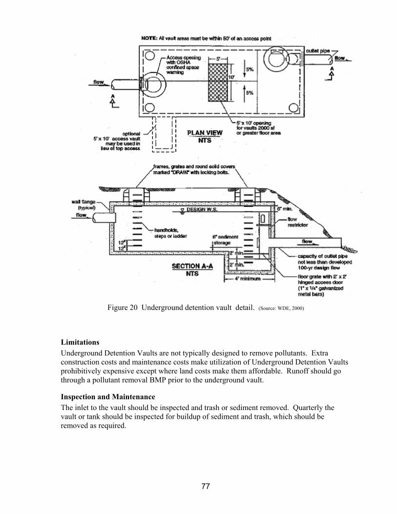
Figure 20 Underground detention vault detail. (Source: WDE, 2000)
Limitations Underground Detention Vaults are not typically designed to remove pollutants. Extra construction costs and maintenance costs make utilization of Underground Detention Vaults prohibitively expensive except where land costs make them affordable. Runoff should go through a pollutant removal BMP prior to the underground vault.
Inspection and Maintenance The inlet to the vault should be inspected and trash or sediment removed. Quarterly the vault or tank should be inspected for buildup of sediment and trash, which should be removed as required.
77

Sediment Control BMPs
Embedded Silt Fence
Description Water flowing in sheet or shallow flow will carry sediment down a slope and off-site. Embedded Silt Fence (ESF) is a barrier made of geotextile fabric placed along a contour to capture water, slow the flowrate, trap sediment, and allow water to filter through the fabric. ALL SILT FENCE USED WITHIN THE PLANNING JURISDICTION OF THE CITY OF ROGERS MUST BE WIRE REINFORCED/WIRE BACKED.
Applications Small drainage areas with sheet flow or shallow flow.
Design Criteria EMBEDDED SILT FENCE (ESF) USED WITHIN THE PLANNING JURISDICTION OF THE CITY OF ROGERS MUST BE WIRE REINFORCED/WIRE BACKED. It should be placed on a contour and designed to hold runoff from the 10 year storm from an area of 100 sq. ft for each foot of fence. The maximum depth of retained water on the upstream side of the fence should be two feet. The maximum slope length above the fence should be no more than 100 feet. The maximum slope above the fence is 1:1. The fabric shall be buried in a trench that is at least eight inch deep and eight inches wide as shown below. The fabric shall be place on the upstream side of the posts. Post shall be made of metal (T-post) or wood (2”x2”) and placed no more than six feet apart.
78

79
PASSED THIS _____ DAY OF _________________, 2004. APPROVED: _____________________________________ Attest: __________________________