Plasma etch control by means of physical plasma parameter measurement with HERCULES

Introduction and overview of plasma control(with emphasis on boundary conditions arising from diagnostic limitations)
5th IAEA DEMO Programme Workshop
Daejeon, South Korea, 7 - 10 May 2018
Wolfgang Biel1,2 and contributors to EUROfusion WPDC1Institute of Energy- and Climate Research, Forschungszentrum Jülich GmbH, Germany2Department of Applied Physics, Ghent University, Belgium

W. Biel | Introduction to plasma control, 5th IAEA DPW, Daejeon, Korea, 07th May 2018 | Page 2
W. Biel1,2, R. Albanese3, R. Ambrosino3, M. Ariola4, M. v. Berkel17, I. Bolshakova18, K.-J. Brunner16 , R. Cavazzana8,
M. Cecconello5, S. Conroy5, A. Dinklage16, I. Duran6, R. Dux7, T. Eade20, S. Entler6, G. Ericsson5, E. Fable7,
D. Farina15, Th. Franke7,9, L. Giacomelli15, L. Giannone7, W. Gonzalez1, A. Hjalmarsson5, M. Hron6, F. Janky7,
A. Kallenbach7, J. Kogoj13, R. König16, O. Kudlacek7, R. Luis11, A. Malaquias11, O. Marchuk1, G. Marchiori8,
M. Mattei19, F. Maviglia3,9, G. De Masi8, D. Mazon12, H. Meister7, K. Meyer13, A. Mlynek7, S. Nowak15, Ch. Piron8,
A. Pironti3, H. Policarpo11, N. Rispoli15, V. Rohde7, G. Sergienko1, S. El Shawish14, M. Siccinio7,9, A. Silva11,
F. da Silva11, C. Sozzi15, M. Tardocchi15, M. Tokar1, W. Treutterer7, A. Vale11, H. Zohm7
1Institut für Energie und Klimaforschung, Forschungszentrum Jülich GmbH, Germany2Department of Applied Physics, Ghent University, Belgium3Università degli Studi di Napoli Federico II, Consorzio CREATE, Italy4Universita’ di Napoli “Parthenope”, Consorzio CREATE, Italy5Department of Physics and Astronomy, Uppsala University, Sweden6Institute of Plasma Physics, Czech Academy of Science, Praha, Czech Republic7Max-Planck-Institut für Plasmaphysik, Garching, Germany8Consorzio RFX (CNR, ENEA, INFN, Università di Padova), Padova, Italy9EUROfusion Power Plant Physics and Technology (PPPT) department, Garching, Germany10Department of Physics, Universita ‘degli Studi di Milano-Bicocca, Milano, Italy11Instituto de Plasmas e Fusão Nuclear, IST, Universidade de Lisboa, Portugal12CEA, IRFM F-13108 Saint Paul-lez-Durance, France13Cosylab, Ljubljana, Slovenia14Jožef Stefan Institute, Ljubljana, Slovenia15IFP-CNR, Istituto di Fisica del Plasma, Milano, Italy16Max-Planck-Institut für Plasmaphysik, Greifswald, Germany17DIFFER institute, Eindhoven, The Netherlands 18Magnetic sensor laboratory, Lviv, Ukraine19Universita’ della Campania “Luigi Vanvitelli”, Consorzio CREATE, Italy20CCFE, Culham Science Centre, Abingdon, Oxfordshire, OX14 3DB, United Kingdom
Contributors to EUROfusion WPDC

W. Biel | Introduction to plasma control, 5th IAEA DPW, Daejeon, Korea, 07th May 2018 | Page 3
1. Cover all DEMO control needs - diagnostics are only for control
2. Provide high reliability, availability (and accuracy) of plasma operation
over long time
• optimise fusion performance (go near to operational limits)
• avoid disruptions (machine damage)
(keep distance from operational limits, install redundant systems)
• caveat: strong adverse effects acting on diagnostic components
while possibilities for maintenance are limited
3. Minimum impact on the tritium breeding rate (TBR) and shielding
• only limited space available for diagnostic integration (TBR < 0.04) prefer
diagnostic systems with low space consumption
4. Minimise efforts
• Prefer proven methods and technologies (reduce risks and development effort)
• Standardisation / modularization of components and integration approach
Requirements and challenges for theDEMO diagnostic and control system
impact on definitionof plasma scenario(controllability)
impact on machinedesign

W. Biel | Introduction to plasma control, 5th IAEA DPW, Daejeon, Korea, 07th May 2018 | Page 4
Radiation issues for plasma diagnostic front end components on EU DEMO
Typical irradiation levels behind the blanket:
ITER: 1 GGy1020 n/cm2
DEMO: 1.2 GGy (gamma + n, OB)12 GGy (gamma + n, IB)
> 1021 n/cm2 (OB)1022 n/cm2 (IB)
DEMO neutron flux map
Neutron fluences behind the EU DEMO blanket are 10 .. 100 times larger than on ITER
(T. Eade, CCFE)
(G. Vayakis,
ITER_D_26ZGC3)
(T. Eade, CCFE)
Radiation effects on diagnostic components:• radiation-induced conductivity (RIC)• radiation-induced thermoelectric sensitivity (RITES)• radiation-induced absorption (RIA)• radio-luminescence• thermal conductivity decrease• volume changes (swelling)• …..
Active cooling required for all front-end components.
W. Biel | Introduction to plasma control, 5th IAEA DPW, Daejeon, Korea, 07th May 2018 | Page 5
1019
1020
1021
1022
1023
4.0
1022
n·m-2
9·1019
n·m-2
2.0
1.0
0
3.0
ITER lifetime fluences
for ex-vessel sensors
Se
nsitiv
ity,
S x
10
4 (
mV
·A-1·T
-1)
Fluence, F (n·m-2)
1
2
1019
1020
1021
1022
1023
1024
2.0
2.5
1.5
1.0
0
Sen
sitiv
ity, S
(m
V·A
-1·T
-1)
Fluence, F (n·m-2)
1
2
0.5
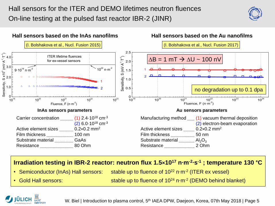
Hall sensors based on the InAs nanofilms Hall sensors based on the Au nanofilms
no degradation up to 0.1 dpa
Hall sensors for the ITER and DEMO lifetimes neutron fluences
On-line testing at the pulsed fast reactor IBR-2 (JINR)
Irradiation testing in IBR-2 reactor: neutron flux 1.5×10¹⁷ n∙m-2∙s-1 ; temperature 130 °C
• Semiconductor (InAs) Hall sensors: stable up to fluence of 1022 n∙m-2 (ITER ex vessel)
• Gold Hall sensors: stable up to fluence of 1024 n∙m-2 (DEMO behind blanket)
InAs sensors parameters
Carrier concentration (1) 2.4·1018 cm-3
(2) 6.0·1018 cm-3
Active element sizes 0.2×0.2 mm2
Film thickness 100 nm
Substrate material GaAs
Resistance 80 Ohm
Au sensors parameters
Manufacturing method (1) vacuum thermal deposition
(2) electron-beam evaporationActive element sizes 0.2×0.2 mm2
Film thickness 50 nm
Substrate material Al2O3
Resistance 2 Ohm
(I. Bolshakova et al., Nucl. Fusion 2015) (I. Bolshakova et al., Nucl. Fusion 2017)
B = 1 mT U ~ 100 nV

W. Biel | Introduction to plasma control, 5th IAEA DPW, Daejeon, Korea, 07th May 2018 | Page 6
First mirror lifetime investigations for DEMO: erosion(modelling for deposition ongoing)
M. Z. Tokar, submitted to: Plasma Science and
Technology, Ed. Haikel Jelassi, InTechOpen
Geometry investigated: Mirror surface erosion per full power year:
Duct geometry required for 1st mirror protection against erosion (vacuum conditions):• h/ρ0 > 80 for IR diagnostics (interferometry, thermography)• h/ρ0 > 100 for VIS spectroscopy• h/ρ0 > 200 for VUV spectroscopy
kinetic
calculation
diffusion
approximation

W. Biel | Introduction to plasma control, 5th IAEA DPW, Daejeon, Korea, 07th May 2018 | Page 7
Improvement of first mirror erosion lifetimeby a gas target in the duct
Mirror surface erosion per full power year:
M. Z. Tokar, submitted to: Plasma Science and
Technology, Ed. Haikel Jelassi, InTechOpen
Duct geometry required for 1st mirror protection against erosion• h/ρ0 > 40 for IR diagnostics (interferometry, thermography)• h/ρ0 > 50 for VIS spectroscopy• h/ρ0 > 80 for VUV spectroscopy
(dashed – double dotted line corresponding to gas target in duct with density nH = 3e19 m-3, mean free path ~ 10 cm)

W. Biel | Introduction to plasma control, 5th IAEA DPW, Daejeon, Korea, 07th May 2018 | Page 8
EU DEMO concept for implementation of diagnostic front-
end: durable components; retracted mounting positions
• In front of blanket and divertor:
• No diagnostic components
• Within blanket area:
• Microwave antennae+waveguides (metallic)
• tube-like penetrations for spectroscopy, interferometry/polarimetry, neutron+gamma
• Behind blanket:
• Optical mirrors (metallic) and beam paths
• magnetic sensors (metal+ceramic) & cablingt.b.d. (depending on durability)
• Port plugs:
• signal routing, mirror labyrinths
• penetrations (cables, tubes) and windows
• Within/behind divertor target:
• Implementation of sheath voltage or thermo-current measurement
• [narrow sightlines using gaps betweencassettes or tube-like access in low power region, t.b.d.]
equatorialports
vertical ports

W. Biel | Introduction to plasma control, 5th IAEA DPW, Daejeon, Korea, 07th May 2018 | Page 9
EU DEMO main diagnostic methods (1): magnetic sensors
(A. Pironti et al.)
Estimation of vertical plasma position
Zp using magnetic diagnostics
Conclusion:• Fast changes (~ 10 ms) of plasma
position cannot be followed by ex-
vessel sensors only (eddy current
shielding by the vacuum vessel)
Simulation results:Coil based sensors:• time integration of low signals over long pulses
Hall sensors: • very low signals, temperature dependent
Open issue: irradiation hardness of in-
vessel magnetic sensors on DEMO

W. Biel | Introduction to plasma control, 5th IAEA DPW, Daejeon, Korea, 07th May 2018 | Page 10
Simulation of equilibrium control based on in-vesselmagnetics: loss of confinement event
M. Ariola et al, SOFT 2018 (submitted)
change of plasma
position up to 25 cm
control power to PF
coils up to 700 MW
Equilibrium control is marginal even under optimistic assumptions
This simulation is
assuming ideal
in-vessel magnetic
sensors
Adding small noise
to the magnetic
measurements leads
to loss of control
voltages at PF coils
go to saturation

W. Biel | Introduction to plasma control, 5th IAEA DPW, Daejeon, Korea, 07th May 2018 | Page 11
EU DEMO main diagnostic methods (2):Microwave diagnostics
Diagn. methods: ➢ reflectometry➢ ECE
Control tasks tobe covered:
➢ ne profile in gradient region➢ Te profile➢ plasma position and shape➢ plasma instabilities
Implementation: ➢ > 100 antennae distributed toroidally and poloidally (LFS, HFS, upper, x-point)➢ integration of antennae + waveguides in slim poloidal diagnostic cassettes➢ routing of waveguides to upper port (attached to „blanket bananas“)➢ Microwave feedthroughs or ceramic windows near upper port
A. Silva,
A. Malaquias,
C. Sozzi,
G. de Masi, et al.
Integration study of MW antennae
Predicted gap accuracy:
green: high (few cm)
red: low (~ 10 cm)
G. Marchiori et al., SOFE 2017R. Luis et al., SOFE 2017
A. Malaquias et al., SOFE 2017
In case of 2 full poloidal sectors (< 25 cm each)the effect on TBR would be TBR < 0.01

W. Biel | Introduction to plasma control, 5th IAEA DPW, Daejeon, Korea, 07th May 2018 | Page 12
EU DEMO main diagnostic methods (3):IR polarimetry/interferometry
Diagn. methods: ➢ IR interferometry (combined with polarimetry), ~ 10 µm wavelength
Control tasks tobe covered:
➢ ne in core plasma (r/a < 0.7)➢ plasma position and shape (startup phase!)➢ plasma instabilities (contribute)
Implementation: ➢ Laser beams entering at eq. ports; IR windows at port plate or bioshield t.b.d.➢ first mirror and retro-reflectors behind blanket (inboard or outboard, tbd)
Sightline arrangement for DEMO system to be based on theITER layout:
poloidal beams or toroidal beams
(A. Mlynek, K.-J. Brunner, et al., IPP)
Option for vertical position control!
Protection of retro-reflectors?
First mirrors can be well protected!
Mid-plane allows only 3 different beam paths?

W. Biel | Introduction to plasma control, 5th IAEA DPW, Daejeon, Korea, 07th May 2018 | Page 13
• Two contradicting requirements for power exhaust control are driving the requirements:
• qdiv < divertor wall limit – margin
• Psep > PLH + margin
• Actuators for divertor control: impurity injection for plasma core (Xe) and for divertor radiation (Ar)
Diagnostic contributions planned for power exhaust control:
1) Measurement of core radiation (H mode control)
• Psep = Pheat – Prad,core
2) Measurement of divertor thermo-current
• based on sheath voltage due to plasma-wall contact
3) Spectroscopic detection of divertor detachment
• T, v, location of ionisation front, fluxes(?)
• check for X-point MARFE (upper limit of detachment)
• assuming that full detachment is sufficient for divertor protection
4) Spectroscopic measurement of W erosion flux at divertor strike-point
• control (limitation) of W erosion of the divertor target needed
• assuming that vanishing W flux is sufficient for divertor protection (non-monotonic relation?)
5) Thermography on divertor target
• needs lines of sight with angle > 30 degrees against divertor target
Approaches for DEMO power exhaust control
small differences of big numbers to be measured
strong background radiation in detached plasma
requires isolated mounting of divertor, low signal only
spatial resolution?
spatial resolution?

W. Biel | Introduction to plasma control, 5th IAEA DPW, Daejeon, Korea, 07th May 2018 | Page 14
Main diagnostic methods in DEMO (4):Divertor thermo-current measurement for detachment control
Principle:
▪ sheath voltage at divertor target depends
on plasma temperature
A. Kallenbach et al., J. Nucl. Mat. 2001 Study on implementation on DEMO:
▪ isolate divertor targets against vacuum vessel
▪ use coolant tubes as shunt resistor
▪ implementation in each divertor target
L. Giannone, IPPS. El-Shawish, JSI/cosylab
Feasibility depends on durability of insulators
against neutron irradiation and on limiting
current generated in cooling pipes by a disruption.
Low signal levels (10…100 mV) are expected.
Shunt resistor (100 µ)

W. Biel | Introduction to plasma control, 5th IAEA DPW, Daejeon, Korea, 07th May 2018 | Page 15
• Diagnostics methods:
• spectroscopy from X-ray to IR
• plasma radiation (power) measurement
• thermography
• Control tasks to be covered:
• radiation control (core, edge, x-point, divertor)
• divertor detachment control
• wall surface temperature control (div. and FW)
• spectroscopic and radiationmeasurements are essential for power exhaust control
• Integration issues:
• first mirrors in protected locations (long ducts)
• secondary mirrors in vessel to guide light toports (1-2 mirrors per channel)
• spatial coverage <150 narrow lines ofsight, space occupation under investigation
• certain sightlines may not be feasible foradvanced divertors
EU DEMO main diagnostic methods (5):spectroscopic and radiation measurements

W. Biel | Introduction to plasma control, 5th IAEA DPW, Daejeon, Korea, 07th May 2018 | Page 16
EU DEMO main diagnostic methods (6)
Diagn. methods: ➢ Neutron and gamma flux measurements + spectroscopy
Measurements: ➢ Fusion power density profile➢ Ion temperature profile in core (from neutron/gamma spectra)➢ ne and Ti profile in core from neutron flux (contribute during burn phase)➢ plasma position and shape (contribute during burn phase)
Implementation: ➢ 2 equatorial system(s) and 2 vertical port system(s) at different toroidal locations, each with ~ 12 beams
➢ straight tubes leaving the ports, ex-bioshield detectors
M. Cecconello,
L. Giacomelli, et al.
Integrated calibra-tion tracking of fluxmonitors (fissionchambers), activation foils andthermal power measurements

W. Biel | Introduction to plasma control, 5th IAEA DPW, Daejeon, Korea, 07th May 2018 | Page 17
Control quantity Operational limits Diagnostics Actuators + interactions
Plasma current safety factor limit (q95) magnetic diagnostics(in-vessel and ex-vessel)
CS coilsauxiliary heating
Plasma position and shape, incl. vertical stability
wall loads (FW and div.)max. z / VDE disruption
magnetic diagnosticsMW reflectometry, ECEneutron/gamma diagnosticsIR polarimetry/interferometry
PF + CS coils(in-vessel coils?)auxiliary heatinggas injection
Plasma density density limit MW reflectometry (edge)IR polarimetry/interferometry
pellet injection (fuel)gas injectionpumping system
Plasma radiation, impurity mixture, Zeff
radiation limitLH threshold
Spectroscopy+radiation meas.Uloop
impurity gas injectionauxiliary heating
Fusion power wall loads (FW and div.)LH threshold
Neutron diagnosticsFW/blanket and div. power (for calibration only)
pellet injection (fuel)impurity gas injectionauxiliary heating
Divertor detachment and heat flux control
divertor wall loads LH threshold
Spectroscopy+radiation meas.ThermographyDivertor thermo-currentsMW reflectometry, ECE
gas injection (impurities + fuel)pellet injection (fuel)PF coilspumping system
(MHD) plasma instabilities various ( disruptions) MW reflectometry, ECEIR polarimetry/interferometrymagnetic diagnosticsneutron/gamma diagnostics
auxiliary heatingECCDPF coils
Plasma pressure beta limit magnetic diagnosticsdensity and temperature meas.
auxiliary heatingfuel and impurity injection
Unforeseen events (impurityingress, component failure)
various ( disruptions) all all
EU DEMO: summary of the diagnostic&control concepte
qu
ilib
r. c
on
tro
lki
net
icco
ntr
ol
inst
abili
ties
/eve
nts

W. Biel | Introduction to plasma control, 5th IAEA DPW, Daejeon, Korea, 07th May 2018 | Page 18
• Diagnostic implementation and performance on DEMO are limited by:
• degradation of front-end components by ionising radiation, erosion and deposition
retracted mounting of front-end components lower spatial resolution, lower accuracy
selection of robust diagnostic methods and components only
• low space available for diagnostics, remote maintenance and integration issues
• Actuator properties are limited as well:
• only limited amount of auxiliary power can be afforded
• ex-vessel PF coils act slowly, eddy current shielding by blanket and vacuum vessel
• Most critical issues and risks:
• feasibility/durability of in-vessel magnetic measurements; fast equilibrium control
• feasibility of power exhaust (divertor detachment) control
• unforeseen events not captured by plasma models disruptions
• large number of measurement channels to be integrated
• Feasibility of control system will have impact on:
• plasma scenario (operational space for reliable control)
• machine design / size and architecture
Some conclusions

Loss of plasma control typically ends up in a disruption.
A disruption in a fusion reactor will release an energy of 1..2 GJ within a
short time of a few ms to the first wall.
Reliable plasma control in a reactor means:
• Aiming for less than one (full energy) disruption in 10…100 full
power years of operation.
Reliable plasma control
W. Biel | Introduction to plasma control, 5th IAEA DPW, Daejeon, Korea, 07th May 2018 | Page 19


![INTEGRATED PLASMA CONTROL FOR HIGH ......Concluding remarks are made in Section 6, along with comments on application of integrated plasma control to ITER [9]. 2. Integrated Plasma](https://static.fdocuments.us/doc/165x107/60b9a269f11a5012e77b7d54/integrated-plasma-control-for-high-concluding-remarks-are-made-in-section.jpg)