Introduction
47
1 Introduction http://www.ieee802.org/1/files/public/docs2010/liaison-nfinn-split-horizon-vid-filtering -0710-v04.pdf describes in pages 19 and 20 the “ Optimal distribution of data: Non-802.1aq” and “Using VIDs for manually configured optimum data distribution” The following slides expand the description in those two pages with Multi (e.g. 2) domain E-LAN example 1 root and 2 roots E-Tree examples Internal node configuration details for E-LAN and E-Tree cases, including Relay VIDs and switch configurations Egress filtering Egress and ingress VID translation, Per domain local VID values Per link local VID values (used in transport networks) Primary VID values in MEPs and MIPs v02 adds some E-Tree cases, corrections of some mistakes in v01, an evaluation of UP and Down MEP/MIP primary VID values and support of those multi-VID models in G.8021 v03 includes some corrections in the B1 and B2 node expansion figures on slides 5,17,20,26 v04 includes G.8021 functional models for nodes B1 to B5 for E-LAN, 2 nd type E- Tree, 3 rd type E-Tree and 4 th type E-Tree in slides 31 to 43; while developing those slides it was noticed that it is possible to enhance the egress filtering for the 2 nd , 3 rd and 4 th E-Tree cases; this is also reflected in slides 14-15, 17-18 and 20-21. In addition, interworking cases between nodes with split-horizon port group designs and nodes with multi-vid designs for E- LAN and 2 nd type E-Tree are illustrated in slides 45-46.
-
Upload
hammett-barr -
Category
Documents
-
view
18 -
download
0
description
Introduction. http://www.ieee802.org/1/files/public/docs2010/liaison-nfinn-split-horizon-vid-filtering-0710-v04.pdf describes in pages 19 and 20 the “ Optimal distribution of data: Non-802.1aq ” and “ Using VIDs for manually configured optimum data distribution ” - PowerPoint PPT Presentation
Transcript of Introduction

1
Introduction
http://www.ieee802.org/1/files/public/docs2010/liaison-nfinn-split-horizon-vid-filtering-0710-v04.pdf describes in pages 19 and 20 the “Optimal distribution of data: Non-802.1aq” and “Using VIDs for manually configured optimum data distribution”
The following slides expand the description in those two pages with Multi (e.g. 2) domain E-LAN example 1 root and 2 roots E-Tree examples Internal node configuration details for E-LAN and E-Tree cases, including
Relay VIDs and switch configurations Egress filtering Egress and ingress VID translation, Per domain local VID values Per link local VID values (used in transport networks) Primary VID values in MEPs and MIPs
v02 adds some E-Tree cases, corrections of some mistakes in v01, an evaluation of UP and Down MEP/MIP primary VID values and support of those multi-VID models in G.8021
v03 includes some corrections in the B1 and B2 node expansion figures on slides 5,17,20,26
v04 includes G.8021 functional models for nodes B1 to B5 for E-LAN, 2nd type E-Tree, 3rd type E-Tree and 4th type E-Tree in slides 31 to 43; while developing those slides it was noticed that it is possible to enhance the egress filtering for the 2nd, 3rd and 4th E-Tree cases; this is also reflected in slides 14-15, 17-18 and 20-21. In addition, interworking cases between nodes with split-horizon port group designs and nodes with multi-vid designs for E-LAN and 2nd type E-Tree are illustrated in slides 45-46.

2
Configuration of ‘I’ and ‘V’ relay-VIDs, local VIDs, egress filtering and VID translation
Internal configuration of node B1 with the E-LAN FID including the ‘I’ and ‘V’ relay-VID learning and forwarding processes and VID translation at the egress ports
B1B1
B1
B2
B3P21
P23
P32
P31
P13P12
P10
P20
P30
C12
C2
C3
B1
B2
B3
VV
IV
II
V
V
V
C12
C2
C3
V
V
V,I
V,I
V,I
V
X: Local VIDX: Relay-VID
VI
XY, Y X: relay-VID X to local-VID Y Translation at egress port
IV
V
I
VI
IV IV
IV
VI
VI
I
V SVL
C11
IV
IV
IV
IV
V
V
I
I
C11
P11
V
V,IIV
P13
P12
P10
P11
E-LAN (1 domain)
I
I
I
VLAN has common local VID value ‘I’ on the inner links B1-
B2, B2-B3 and B3-B1
SVL: Shared VLAN Learning
VLAN has 2 relay-VID values ‘I’ and ‘V’ which operate in SVL mode
VID Translation at egress port
V
V
V
V

3
Extension of previous example with a 2nd domain with edge nodes B2-B4-B5
VLAN with two domains interconnected by node B2
Next slide illustrates Need for two inner domain
VIDs (Ia, Ib) in this case Relay-VIDs registered at
each output port VID translation at egress
ports VID values used on the links
between the nodes Detailed architecture in node
B2 (FID with 3 relay-VIDs, SVL, VID Translation)
B1
B2
B3P21
P23
P32
P31
P13P12
P10
P20
P30
C12
C2
C3
C52
C51
P11
E-LAN (2 domains)
B4 B5
P24P25
P52P54
P42P45
P50
P40C4
P55
VLAN has two domains with a full mesh of links
C11

4
B1
B2
B3
C12
C2
C3
C52
C11
C51
E-LAN (2 domains)
B4 B5C4
B2B2
Ia
V
SVL
IaV
IbV
IaVV
Ia
Ia
Ib
P23
P24
P20
P21V,Ib
Ia
Ia
Ia
V
V
V V
V,Ia
V,Ia,Ib
V,Ia
V
IaV
V,I
bIa
VIa
Ia
V IaV
IaV
VIa
VIa,Ib
V
V,IIa
V
V,IbV
V
V,IbIa
Ib
IbIb
V
V
V
V,IaV,Ia
VV
VV
V,IaIbIb
V
,Ia
V,Ib
VIb
V
Ib
VIb IbV
IbV
V,Ib
IbV Ib
IbV
V,Ib
IaIb
P25
IbV
IbIa
IaV
IaIb
IbVIb
Ia
Ib
VLAN has common local VID value ‘Ib’ on the inner links B2-B4, B4-B5 and B5-B2
VLAN has common local VID value ‘Ia’ on the inner links B1-B2, B2-B3 and B3-B1
VLAN in Node B2 has 3 relay-VID values ‘Ia’, ‘Ib’ and ‘V’
which operate in SVL mode
VID Translation at egress port
X: Local VIDX: Relay-VID XY, Y X: relay-VID X to local-VID Y Translation at egress port SVL: Shared VLAN Learning

5
B1B1
B1
B2
B3P21
P23
P32
P31
P13P12
P10
P20
P30
C12
C2
C3
B1
B2
B3
VV
RV
QP
V
V
V
C12
C2
C3
V
V
V,I
V,I
V,I
V
IR
VR
XY, Y X: relay-VID X to local-VID Y Translation at egress port
IV
IP
V
P
IQVQ
P
IP
V
QIQV
RI
RV
VI
VI
I
V SVL
C11
IV
IV
RV
QV
V
V
Q
P
C11
P11
V
V,IIV
P13
P12
P10
P11
E-LAN (1 domain)
XY, Y X: local-VID Y to relay-VID X Translation at ingress port
RI Q
I
R
Q
P
VID Translation at ingress port
VLAN has different local VID values ‘P’, ‘Q’ and ‘R’ on the inner
links B1-B2, B2-B3 and B3-B1
X: local VIDX: Relay-VID SVL: Shared VLAN Learning
VID translation at the ingress ports in the domain enables the usage of different local VID values on each of the inner domain links. A requirement in transport networks.

6
B1
B2
B3
C12
C2
C3
C52
C11
C51
E-LAN (2 domains)
B4 B5C4
B2B2
Ia
V
SVL
IaV
LV
RVV
P
R
L
P23
P24
P20
P21V,Ib
R
QP
V
V
V V
V,I
V,Ia,Ib
V,I
V
IV
VI
VIa,Ib
V
V,IIV
V,IbV
V
M
LK
V
V
V
V,IaV,Ia
VV
VV
IbL
V,IaLK
Ib
K
V,I
a
V,I
VI
V
KI
K
VMIM
MVMI
L
I
L
V
V,I
IV Ib
IVV,I
RIb
P25
IbV
LIa
PV
PIb
KVK
Ia
K
VLAN has different local VID values ‘P’, ‘Q’ and ‘R’ on the inner
links B1-B2, B1-B3 and B3-B2
VLAN has different local VID values ‘K’, ‘L’ and ‘M’ on the inner
links B2-B4, B2-B5 and B5-B4
IaR
V,IbR
Ia
PV
,Ib
PIQ
VQP
IP
V
QIQV
RI
RV
PIa
RIa
LIbK
Ib
VID Translation at ingress port
X: Local VIDX: Relay-VID XY, Y X: relay-VID X to local-VID Y Translation at egress port SVL: Shared VLAN Learning
XY, Y X: local-VID Y to relay-VID X Translation at ingress port
VID translation at the ingress ports in the domain enables the usage of different local VID values on each of the inner domain links in both domains. A requirement in transport networks.

7
Security in transport networks
In the previous E-LAN examples ingress VID Translation is not deployed at all input ports (e.g. not on P20 in slide 6, not on P20, P21, P23, P24, P25 on slide 4)
With the “Ingress Filtering” parameter for the ports set to ‘disabled’ those VLAN connections are not secured; frames arriving on other input ports of e.g. node B2 with a local VID value ‘V’, ‘Ia’ or ‘Ib’ can enter the E-LAN VLAN (see Red dashed lines)
This security issue is resolved when ingress VID translation is deployed at every input port
This prevents that frames with unexpected local VID values can access the port and intrude the VLANs
B2B2
Ia
V
SVL
IaV
IbV
IaVV
Ia
Ia
Ib
P24; Ingress Filtering = Disabled
P20; Ingress Filtering = Disabled
P21; Ingress Filtering = Disabled
Ib
IaIb
P25; Ingress Filtering = Disabled
IbV
IbIa
IaV
IaIb
IbVIb
Ia
Ib
IbIa
Ia
Ib
Ib
V
V
V
IaV
P23; Ingress Filtering = Disabled

8
VID Translation for E-LAN (2 domains) example
When using different VID values on the links between nodes it is required to identify the ports which form a group and ports which are individual
All individual ports must be associated with a relay VID (R-VID) value identifying Individual ports
Ports which form a group must be associated with a R-VID value identifying that group
Administration of individual ports and grouped ports is done via the Ingress VID Translation tables in each port (see next slide for example)
For node B2 the following applies: Group 1: (P21,P23): R-VID: Ia Group 2: (P24,P25): R-VID: Ib Individual: P20: R-VID: V
For node B5: Group 1: (P52,P54): R-VID: I Individual: P50,P55: R-VID: V
B1
B2
B3P21
P23
P32
P31
P13P12
P10
P20
P30
C12
C2
C3
C52
C11
C51
P11
B4 B5
P24 P25
P52P54
P42P45
P50
P40C4
P55
VID: R
VID: Q
VID: P
VID: M
VID: LVID: K
VID: A
VID: B
VID:C
VID: D
VID: E
VID:F
VID: G

9
Using VIDs for manually configured optimum data distribution for E-LAN (2 domains) example using ingress VID translation on all ports
Bridge Port Can transmit (before xlate)
(Ingress) VID Translation
Egress VID Translation
B2 P20 V, Ia, Ib BV IaB, IbB, VB
P21 V, Ib PIa (Group 1) IbP, VP
P23 V, Ib RIa (Group 1) IbR, VR
P24 V, Ia KIb (Group 2) IaK, VK
P25 V, Ia LIb (Group 2) IaL, VL
B5 P50 V, I DV ID, VD
P52 V LI (Group 1) VL
P54 V MI (Group 1) VM
P55 V, I EV IE, VE
B1 … … … …
B3 … … … …
B4 … … … …

10
Port Group concept in transport networks
The logical concept of a “Port Group” could be maintained in a transport network as a configuration element in the manually configured optimum data distribution for E-LAN connection management
Each port in a node in such E-LAN is marked as either an Individual Port or as a port in a Port Group #i (i≥1)
The ports in a Port Group will see their local VID values translated into a common relay VID value in the ingress VID translation process Relay VID values for the individual and the port group ports have a
node local scope; each node can select those values independent of other nodes

11
E-Tree

12
E-Tree types
There are four types of E-Tree Unidirectional P2MP E-Tree (outside scope of this document) Bidirectional RMP E-Tree with single root and individual leaves Bidirectional RMP E-Tree with multiple roots and individual leaves Bidirectional RMP E-Tree with multiple roots, individual leaves and one or more leaf
groups
The 4th type requires the use of the largest set of relay VID values and local VID values
Relay VIDs identify the frame’s source and potential set of destination ports: R, I, VG1 to VGN
Local VIDs identify the frame’s source port: root, individual leaf, leaf group #i
The 2nd type requires the use of two relay VID values (R, I) and one local VID value per link
Local VID identifies in the frame’s source port: root, individual leaf Ingress VID translation converts local VID value to appropriate relay VID value Egress VID translation converts both relay VID values to same local VID value
The 3rd type requires the use of two relay VID values (R, I) and one or two local VID values per link
Local VID values can not be pruned to single value on the links between the root ports
Next slides illustrate the 2nd, 3rd and 4th E-Tree types and their configuration details from the viewpoint of a transport network

13
E-Tree (1 root, no leaf groups)
Ports Root: R1 Leaf: L1,L2,L3,L4,L51,L52
Local VID values A to G, K, L, P, Q
Relay VID values I, R
Single local VID value for both directions of transport per link, e.g.
B2-B4 link: K
Possible due to usage of ingress and
egress VID translation single root
B1
B2
B3P21
P31
P13P12
P10
P20
P30
L1
L2
L3
L52
R1
L51
P11
B4 B5
P24 P25
P52P42
P50
P40L4
P55
Q
P
LK
A
B
C
D
E
F
G

14
B1
B2
B3
E-Tree (1 root, no leaf groups)
B4 B5
QP
R
R
R
IFRF
AIAR
BIBR
IR
GI
G
I
LK
RR
I I
ILR
L
K
IK
R
R
CICR
R
KI
K
LR
L
I
R
IERE
ID
RD
R
R
PI
PIQ
RQP
IP
RQR
QI
X: Local VIDX: Relay-VID XY, Y X: relay-VID X to local-VID Y Translation at egress port SVL: Shared VLAN Learning
XY, Y X: local-VID Y to relay-VID X Translation at ingress port
L1
L2
L3
L52
R1
L51
L4
A
B
C
E
F
G
D
B2B2
I
R
SVL
LR
P
LP24
P20
P21
P25
PR
KR
K
P I
LI
RB IB
B
KI
RR
Graphical representation of configuration details…
I

15
Using VIDs for manually configured optimum data distribution for E-Tree (1 root, no leaf groups) example
Bridge Port Can transmit (before xlate)
(Ingress) VID Translation
Egress VID Translation
B1 P10 R AI RA
P11 I GR IG
P12 R PI RP
P13 R QI RQ
B2 P20 R BI RB
P21 I PR IP
P24 R KI RK
P25 R LI RL
B3 P30 R FI RF
P31 I QR IQ
B4 P40 R CI RC
P42 I KR IK
B5 P50 R DI RD
P52 I LR IL
P55 R EI RE

16
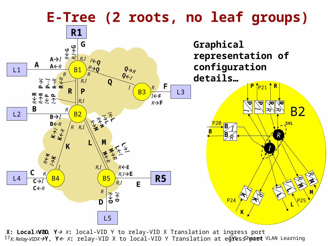
E-Tree (2 roots, no leaf groups)
B1
B3P21
P31
P13P12
P10
P20
P30
L1
L2
L3
R5
R1
L5
P11
B4
P24 P25
P52P42
P50
P40L4
P55
Q
P
LK
A
B
C
D
E
F
G
M
R
B2
B5
Ports Root: R1, R5 Leaf: L1,L2,L3,L4,L5
Local VID values A to G, K, L, M, P, Q, R
Relay VID values I, R
Single local VID value for both directions of transport for subset of links with only individual leaves behind it
B2-B4 link: K
Two local VID values for other subset of links with roots plus individual leaves behind it; i.e.
B1-B2 link: P, R B2-B5 link: L, M
Possible due to usage of ingress and egress
VID translation
1 local VID value
2 local VID values
17
B1
B3
E-Tree (2 roots, no leaf groups)
B4
QR
R
R
R
IFRF
AIAR
BIBR
R,IR
GR
,I
G
R,I
LK
R,IR
I R,I
IL
IL
RM
RM
K
IK
R
R
CICR
R
KI
K
L
I
L
I
M
R
M
R
R,I
RER,IE
ID
RD
R
R
RR
RI
PI
PIQ
RQ
P
IP
IR
RR
R
QRQI
X: Local VIDX: Relay-VID XY, Y X: relay-VID X to local-VID Y Translation at egress port SVL: Shared VLAN Learning
XY, Y X: local-VID Y to relay-VID X Translation at ingress port
L1
L2
L3
R5
R1
L5
L4
A
B
C
E
F
G
D
B2B2
I
R
SVL
MR
P
MP24
P20
P21
P25
PI
RR
KR
K
P I
LI
RB IB
B
KI
R,IR
RR
LI
MR
R
L
M
B5
B2
P
Graphical representation of configuration details…
I

18
Using VIDs for manually configured optimum data distribution for E-Tree (2 roots, no leaf groups) example
Bridge Port Can transmit (before xlate)
(Ingress) VID Translation
Egress VID Translation
B1 P10 R AI RA
P11 R,I GR IG, RG
P12 R,I PI, RR IP, RR
P13 R QI RQ
B2 P20 R BI RB
P21 R,I PI, RR IP, RR
P24 R KI RK
P25 R,I LI, MR IL, RM
B3 P30 R FI RF
P31 I QR IQ
B4 P40 R CI RC
P42 I KR IK
B5 P50 R DI RD
P52 R,I LI, MR IL, RM
P55 R,I EI IE, RE

19
E-Tree (2 roots, 1 leaf group)
B1
B3P21
P31
P13P12
P10
P20
P30
L1
L2
L3
R5
R1
L5
P11
P24 P25
P52P42
P50
P40L4
P55
Q
P
LK
A
B
C
D
E
F
G
M
R
B5
Ports Root: R1, R5 Leaf: L1,L2,L3,L4,L5 Leaf group 1: LG14,LG13
Local VID values A to H,J, K, L, M, N,O,P,Q,
R,S,T
Relay VID values I, R, VG1
2 local VID values
3 local VID values
P41
LG14
H
B4
N O
ST
P33
LG13
J
B2

20
B1
B3
E-Tree (2 roots, 1 leaf group)
B4
Q
R
R
R
R
IFRF
AIAR
BIBR
R,I,VG1R
GR
,I,V
G1
G
R,I,VG1
LK
R,I,VG1
R,VG1
I,VG1 R,I,VG1
VG
1 O
VG
1 O
ILI
LRM
RM
K
IK
R
N
VG
1
N
VG
1
R
CICR
R
KI
KV G
1
NV G
1
N
O
VG
1
O
VG
1
LI
L
I
M
R
M
R
R,I,VG1
RER,I,VG1E
ID
RD
R
IQRQ
VG1T
VG1T QR
QITV
G1TVG1
X: Local VIDX: Relay-VID XY, Y X: relay-VID X to local-VID Y Translation at egress port SVL: Shared VLAN Learning
XY, Y X: local-VID Y to relay-VID X Translation at ingress port
L1
L2
L3
R5
R1
L5
L4
A
B
C
E
F
G
D
B2B2
I
R
SVL
MR
P
M
P24
P20
P21
P25
PI
RR
KR
K
P I
LI
RB IB
B
KI
R,I,VG1
R, VG1
RR
LI
MR
R
L
M
B5
B2
P
Graphical representation of configuration details…
N
ST
LG14
H
LG13
J
R,VG1
O
V G1
JV G
1
JR
J
VG1
NV
G
1
N
N VG
1
SV
G1
SV
G1
S
OV
G1
O
OV
G1
S
VG
1
S
VG
1
P
IP
IR
R
R
R
VG
1S
VG
1S
IP
IP
R
RR
R
R,VG1
H
RH
V
G1
H
VG
1
I,VG1

21
Using VIDs for manually configured optimum data distribution for E-Tree (2 roots, 1 leaf group) example
Bridge Port Can transmit (before xlate)
(Ingress) VID Translation
Egress VID Translation
B1 P10 R AI RA
P11 R,I,VG1 GR IG, RG, VG1G
P12 R,I,VG1 PI, RR, SVG1 IP, RR, VG1S
P13 R,VG1 QI, TVG1 RQ, VG1T
B2 P20 R BI RB
P21 R,I,VG1 PI, RR, SVG1 IP, RR, VG1S
P24 R,VG1 KI, NVG1 RK, VG1N
P25 R,I,VG1 LI, MR, OVG1 IL, RM, VG1O
B3 P30 R FI RF
P31 I,VG1 QR, TVG1 IQ, VG1T
P33 R,VG1 JVG1 RJ, VG1J
B4 P40 R CI RC
P41 R,VG1 HVG1 RH, VG1H
P42 I,VG1 KR, NVG1 IK, VG1N
B5 P50 R DI RD
P52 R,I,VG1 LI, MR, OVG1 IL, RM, VG1O
P55 R,I,VG1 ER IE, RE, VG1E

22
E-LAN/E-Tree in ITU-T models

23
G.8021 E-LAN/E-Tree modelling
802.1Q multi-VID E-LAN/E-Tree models can be 1-to-1 translated into G.8021 ETH layer model
Each relay VID reference point is represented by an ETH_FP (Flow Point) reference point
The multi relay-VID FID is represented by an “ETH Flow Forwarding (FF) process in SVL mode” within an ETH Connection function (see clause 9.1.1/G.8021)
Learning Forwarding
Address Table
ETH_CI
ETH_CI
ETH_CI
(Address, port) Address (Address, {port})
ETH_FF
0
1
2
n
0
1
2
n
0
1
2
n
0
1
2
n
Learning Forwarding
ETH_CI
ETH_CI
0
1
2
n
0
1
2
n
0
1
2
n
0
1
2
n
Address(Address, {port})
(Address, port)
Learning STP_LearningState[]
Learning STP_LearningState[]
Ageing
ETH_CI
Group_Default
Flush_LearnedFlush_Config
MI_FF_MI_FF_
MI_FF_MI_FF_MI_FF_MI_FF_MI_FF_MI_FF_
MI_FF_MI_FF_MI_FF_MI_FF_
MI_FF_MI_FF_
MI_FF_MI_FF_ MI_FF_MI_FF_
‘I’
‘R’ETH/ETH-m
ETH_FP
ETH_AP
....ETH_TFP
ETH/ETH-m_A_MP ETH/ETH-m_A_PP
VID Translation relates local VID with one or
more ETH_FPs
Relay-VID reference point
Set of ETH_FPs represents EISS
ETH_AP represents ISS reference point
G.8021 ETH Flow Forwarding (FF) process in SVL mode
Relay-VID ‘I’ learning and forwarding process
Relay-VID ‘R’ learning and forwarding
process
G.8021 ETH to ETH multiplexing adaptation function

24
MEP and MIP functions in E-LAN/E-Tree

25
Looking at the model of E-LAN Node B2 I am wondering where the MEP and MIP functions should be located
Two locations are considered Red Green
Red locations imply that the VIDTranslation is located betweenthe UP MEPs and the MAC Relay, which is not consistent with itscurrent location in the clause 6.9Support of the EISS function
Green locations are consistent with802.1Q functionality order, but requireextensions to the G.8021 MEP Sink andMIP Sink functions, which currently do notsupport to read OAM from “multiple VIDs”
MEPs and MIPs in these E-LAN cases
B2B2
Ia
V
SVL
IaB
LV
RV
P
R
L
P23
P24
P20
P21
Ib
RIb
P25
IbB
LIa
PV
PIb
KVK
Ia
K
PIa
RIa
LIbK
Ib
VBVB

26
MEPs and MIPs in these E-Tree cases
Looking at the model of E-Tree Node B2 I am wondering where the MEP and MIP functions should be located
Two locations are considered Red Green
Red locations imply that the VIDTranslation is located betweenthe UP MEPs and the MAC Relay, which is not consistent with itscurrent location in the clause 6.9Support of the EISS function
Green locations are consistent with802.1Q functionality order
Both Red and Green locations requireextensions to the G.8021 MEP Sink and MIP Sinkfunctions to support reading from “multiple VIDs”
B2B2
I
R
SVL
MR
P
MP24
P20
P21
P25
PI
RR
KR
K
P I
LI
RB IB
B
KI
RR
LI
MR
R
L

27
Ia
IaB
MEP and MIP primary VID assignments in E-LAN node B2
Up MEP and Half MIP functions have different
primary VID (Ia) than Down MEP/Half MIP (V)
Up MEP and Half MIP functions have different primary VID (Ib) than Down MEP/Half MIP (V)
MAC Relay
Ib Ia V
LAN
Ia..
V..
Ib..
Primary VID: Ib
Primary VID: IbPrimary VID: V
Primary VID: V
P24 and P25
Ia Ib V
LAN
Ib..
V..
Ia..
Primary VID: Ia
Primary VID: IaPrimary VID: V
Primary VID: V
P21 and P23
V Ib V
LAN
IbB
VB
VB
Primary VID: V
Primary VID: VPrimary VID: V
Primary VID: V
P20
Up and Down MEP and Half MIP functions have same primary VID (V)
Primary VID values for the Up MEP/HalfMIP functions on the three port sets are different (V, Ia and Ib); configuration should be performed carefully

28
R
R..
MEP and MIP primary VID assignments in 3rd type E-Tree node B2
Up MEP and Half MIP functions have different
primary VID (I) than Down MEP/Half MIP (R)
MAC Relay
I R
LAN
R..
I..
Primary VID: I
Primary VID: IPrimary VID: R
Primary VID: R
P20 and P24
I I R
LAN
I..
R..
I..
Primary VID: R
Primary VID: RPrimary VID: R
Primary VID: R
P21 and P25
Up and Down MEP and Half MIP functions have same primary VID (R)
Primary VID values for the Up MEP/HalfMIP functions on the two port sets are different (R and I); configuration should be performed carefully

29
R
R..
MEP and MIP primary VID assignments in 4th type E-Tree node B2
Up MEP and Half MIP functions have different
primary VID (I) than Down MEP/Half MIP (R)
MAC Relay
I R
LAN
RB
IB
Primary VID: I
Primary VID: IPrimary VID: R
Primary VID: R
P20
I I R
LAN
I..
R..
I..
Primary VID: R
Primary VID: RPrimary VID: R
Primary VID: R
P21 and P25
Up and Down MEP and Half MIP functions have same primary VID (R)
Primary VID values for the Up MEP/HalfMIP functions on the three port sets are different (R and I); configuration should be performed carefully
VG
1..
VG1 VG1
VG
1..
VG1
VG
1N
I VG1 R
LAN
VG
1N
RK
IK
Primary VID: I
Primary VID: IPrimary VID: R
Primary VID: R
P24
Up MEP and Half MIP functions have different
primary VID (I) than Down MEP/Half MIP (R)

30
G.8021 MEP/MIP functions
G.8021 ETH MIP function has single ETH_FP To support the multi-VID E-Tree the G.8021 MIP function should get
multiple ETH_FPs OAM XXM frames may ingress on each of those ETH_FPs and the
associated XXR frames may egress on the primary_ETH_FP
G.8021 specifies ETH MEP and ETHG MEP functions ETH MEP function contains a single ETH_FP ETHG MEP function contains multiple ETH_FPs
OAM frames can be read/extracted from one ETH_FP only OAM frames can be generated/inserted into one ETH_FP only
The multi-VID E-LAN/E-Tree models require and ETH MEP function with multiple ETH_FPs, with reading/extracting capabilities of OAM frames on every ETH_FP and generating/inserting capabilities of OAM frames on the primary_ETH_FP only
ETH and ETHG MEP functions could be merged into one ETH MEP function, or alternatively the ETH MEP function can be left unchanged and the ETHG MEP function can be extended to read/extract OAM from every ETH_FP

31
G.8021 nodal functional models for E-LAN and E-Tree cases
Slides 32-34: E-LAN
Slides 35-37: E-Tree, 2nd type
Slides 38-40: E-Tree, 3rd type
Slides 41-43: E-Tree, 4th type

32
B1
G.8021 nodal functional models for E-LAN (2 domains) example
FF(I)FF(V)
P13P10 P11
G G GA A P P
P12
Q QA
P23 P24 P25
B2 FF(Ib)
P20 P21
P P PB B R R K K
FF(Ia)FF(V)
L LB R LKB
Local VID ETH_FP mapping
represents “Ingress VID Translation” and
provides security
Local VID value
ETH_FP(V) is optional in this case;
could be deleted
ETH_FP Local VID mapping
represents “Egress VID Translation”
Connecting ETH_FF(x) with
ETH_FP represents “Egress Filtering”

33
P30 P31
B3
Q QF F
FF(I)
R R
P32
FF(V)
F
P45P40 P42
B4
KC C
FF(I)
M
FF(V)
KC M
G.8021 nodal functional models for E-LAN (2 domains) example

34
P50 P52
B5
L LD D
FF(I)
M M
P54
E E
P55
FF(V)
ED
G.8021 nodal functional models for E-LAN (2 domains) example
B1
B2
B3
P21
P23
P32
P31
P13
P12
P10
P20
P30
C12
C2
C3
C52
C11
C51
P11
B4 B5
P24 P25
P52
P54
P42
P45
P50
P40C4 P55
VID: R
VID: Q
VID: P
VID: M
VID: LVID: K
VID: A
VID: B
VID:C
VID: D
VID: E
VID:F
VID: G

35
B1
G.8021 nodal functional models for 2nd type E-Tree (2 domains) example
FF(I)FF(R)
P13P10 P11
G GA P P
P12
Q QA
P24 P25
B2
P20 P21
B K K
FF(I)FF(R)
L LB P P

36
P30 P31
B3
Q QF
FF(I)FF(R)
F
P40 P42
B4
KC
FF(I)FF(R)
KC
G.8021 nodal functional models for 2nd type E-Tree (2 domains) example

37
P50 P52
B5
D
FF(I)
E E
P55
FF(R)
D
G.8021 nodal functional models for 2nd type E-Tree (2 domains) example
L L
B1
B2
B3
P21
P31
P13P12
P10
P20
P30
L1
L2
L3
L52
R1
L51
P11
B4 B5
P24P25
P52P42
P50
P40L4P55
Q
P
LK
A
B
C
D
E
F
G

38
B1
G.8021 nodal functional models for 3rd type E-Tree (2 domains) example
FF(I)FF(R)
P13P10 P11
G G GA P P
P12
Q QA
P24 P25
B2
P20 P21
B K K
FF(I)FF(R)
L L MB
R R
P P R R M

39
P30 P31
B3
QF
FF(I)FF(R)
F
P40 P42
B4
KC
FF(I)FF(R)
KC
G.8021 nodal functional models for 3rd type E-Tree (2 domains) example
Q

40
P50 P52
B5
D
FF(I)
E E
P55
FF(R)
ED
G.8021 nodal functional models for 3rd type E-Tree (2 domains) example
B1
B3
P21
P31
P13P12
P10
P20
P30
L1
L2
L3
R5
R1
L5
P11
B4
P24 P25
P52P42
P50
P40L4 P55
Q
P
LK
A
B
C
D
E
F
G
M
R
B2
B5
L L M M

41
B2 FF(VG1)
B1 FF(VG1)
G.8021 nodal functional models for 4th type E-Tree (2 domains) example
FF(I)FF(R)
P13P10 P11
G G GA P P
P12
Q QA
P24 P25P20 P21
B K K
FF(I)FF(R)
L L MB
R R
P P R R M
G T TS S
S S N N O O

42
B4 FF(VG1)
B3 FF(VG1)
P30 P31
QF
FF(I)FF(R)
F
P40 P42
C K
FF(I)FF(R)
KC
G.8021 nodal functional models for 4th type E-Tree (2 domains) example
Q T T
P33
J JJ
P41
H HHN N

43
B5 FF(VG1)
P50 P52
D
FF(I)
E E
P55
FF(R)
ED
G.8021 nodal functional models for 4th type E-Tree (2 domains) example
B1
B3
P21
P31
P13P12
P10
P20
P30
L1
L2
L3
R5
R1
L5
P11
P24 P25
P52P42
P50
P40L4 P55
Q
P
LK
A
B
C
D
E
F
G
M
R
B5
P41
LG14
H
B4
N O
ST
P33
LG13
J
B2
L L M M O O E E
44
Interworking split-horizon port group model with multi-vid model

45
E-LAN interworking example
Nodes designed according to the split-horizon port group model are able to interwork with nodes designed according to the multi-vid model
Nodes B1, B2, B4 could be using split-horizon port groups (SH)
Nodes B3, B5 could be using multi-vid model (MV)
Both node types deploy a common Local VID approach, which guarantees interworking between these two node types
Note – Any other combination of SH and MV node types also interworks
B1SH
B2SH
B3MV
P21P23
P32
P31
P13P12
P10
P20
P30
C12
C2
C3
C52
C11
C51
P11
B4SH
B5MV
P24 P25
P52P54
P42P45
P50
P40C4
P55
VID: R
VID: Q
VID: P
VID: M
VID: LVID: K
VID: A
VID: B
VID:C
VID: D
VID: E
VID:F
VID: G

46
E-Tree, 2nd type interworking example
Nodes designed according to the split-horizon port group model are able to interwork with nodes designed according to the multi-vid model
Nodes B1, B4 could be using split-horizon port groups (SH)
Nodes B2, B3, B5 could be using multi-vid model (MV)
Both node types deploy a common Local VID approach, which guarantees interworking between these two node types
Note – Any other combination of SH and MV node types also interworks
P21
P31
P13P12
P10
P20
P30
L1
L2
L3
L52
R1
L51
P11
P24 P25
P52P42
P50
P40L4
P55
Q
P
LK
A
B
C
D
E
F
G
B1SH
B2MV
B3MV
B4SH
B5MV
47
E-Tree, 3rd and 4th types interworking
The 3rd and 4th type E-Tree cases can not be supported by means of split-horizon port groups. As such, there is no interworking requirement for multi-vid designs of those two E-Tree cases.