Introducing IBM FileNet Business Process Manager Introducing IBM FileNet Business Process Manager...
280
ibm.com/redbooks Introducing IBM FileNet Business Process Manager Wei-Dong Zhu Eric Adel William Benjamin Imtiaz A Khan Mike Marin Mark Yingling Business process design Integration with external systems and services Step-by-step instructions
-
Upload
truongnhan -
Category
Documents
-
view
216 -
download
1
Transcript of Introducing IBM FileNet Business Process Manager Introducing IBM FileNet Business Process Manager...

ibm.com/redbooks
Introducing IBM FileNetBusiness Process Manager
Wei-Dong ZhuEric Adel
William BenjaminImtiaz A Khan
Mike MarinMark Yingling
Business process design
Integration with external systems and services
Step-by-step instructions
Front cover


Introducing IBM FileNet Business Process Manager
August 2008
International Technical Support Organization
SG24-7509-00

© Copyright International Business Machines Corporation 2008. All rights reserved.Note to U.S. Government Users Restricted Rights -- Use, duplication or disclosure restricted by GSA ADPSchedule Contract with IBM Corp.
First Edition (August 2008)
This edition applies to Version 4, Release 0 of IBM FileNet Business Process Manager (product number 5724-R76).
Note: Before using this information and the product it supports, read the information in “Notices” on page vii.

Contents
Notices . . . . . . . . . . . . . . . . . . . . . . . . . . . . . . . . . . . . . . . . . . . . . . . . . . . . . . viiTrademarks . . . . . . . . . . . . . . . . . . . . . . . . . . . . . . . . . . . . . . . . . . . . . . . . . . . vii
Preface . . . . . . . . . . . . . . . . . . . . . . . . . . . . . . . . . . . . . . . . . . . . . . . . . . . . . . . ixThe team that wrote this book . . . . . . . . . . . . . . . . . . . . . . . . . . . . . . . . . . . . . . ixBecome a published author . . . . . . . . . . . . . . . . . . . . . . . . . . . . . . . . . . . . . . . . xiComments welcome. . . . . . . . . . . . . . . . . . . . . . . . . . . . . . . . . . . . . . . . . . . . . . xi
第 1 章 概要 . . . . . . . . . . . . . . . . . . . . . . . . . . . . 11.1 ビジネス・プロセス管理 . . . . . . . . . . . . . . . . . . . . . . . . . . . . . . . . . . . . . . . 2
1.1.1 トランザクション・プロセスとコンテンツ中心のプロセス. . . . . . . . 31.2 IBM FileNet Business Process Manager の概要 . . . . . . . . . . . . . . . . . . . . . 31.3 BPM を使用したプロセス設計 . . . . . . . . . . . . . . . . . . . . . . . . . . . . . . . . . . 5
1.3.1 プロセス定義. . . . . . . . . . . . . . . . . . . . . . . . . . . . . . . . . . . . . . . . . . . . 51.3.2 ステップ . . . . . . . . . . . . . . . . . . . . . . . . . . . . . . . . . . . . . . . . . . . . . . . 61.3.3 ルート . . . . . . . . . . . . . . . . . . . . . . . . . . . . . . . . . . . . . . . . . . . . . . . . . 71.3.4 マップ . . . . . . . . . . . . . . . . . . . . . . . . . . . . . . . . . . . . . . . . . . . . . . . . . 71.3.5 期限とタイマー . . . . . . . . . . . . . . . . . . . . . . . . . . . . . . . . . . . . . . . . . . 71.3.6 コンテンツ・イベント . . . . . . . . . . . . . . . . . . . . . . . . . . . . . . . . . . . . 8
1.4 BPM のアプリケーション開発オプション . . . . . . . . . . . . . . . . . . . . . . . . . 81.4.1 IBM FileNet Workplace ( または Workplace XT). . . . . . . . . . . . . . . . . 81.4.2 Business Process Framework (BPF) . . . . . . . . . . . . . . . . . . . . . . . . . 81.4.3 電子フォーム (eForms または Lotus Forms) . . . . . . . . . . . . . . . . . . . 91.4.4 IBM FileNet P8 ポートレットによる ポータル・ユーザー・インター
フェース . . . . . . . . . . . . . . . . . . . . . . . . . . . . . . . . . . . . . . . . . . . . . . . 91.4.5 Web Application Toolkit (WAT) . . . . . . . . . . . . . . . . . . . . . . . . . . . . . . 91.4.6 Process Engine API . . . . . . . . . . . . . . . . . . . . . . . . . . . . . . . . . . . . . 10
1.5 BPM と外部システムとの統合 . . . . . . . . . . . . . . . . . . . . . . . . . . . . . . . . . 101.5.1 Component Integrator . . . . . . . . . . . . . . . . . . . . . . . . . . . . . . . . . . . . 101.5.2 Web サービス . . . . . . . . . . . . . . . . . . . . . . . . . . . . . . . . . . . . . . . . . . 101.5.3 ビジネス・ルール・エンジン . . . . . . . . . . . . . . . . . . . . . . . . . . . . . . 10
1.6 BPM プロセスのモニターと分析 . . . . . . . . . . . . . . . . . . . . . . . . . . . . . . . 111.6.1 プロセス・シミュレーター . . . . . . . . . . . . . . . . . . . . . . . . . . . . . . . . 111.6.2 プロセス・アナライザー. . . . . . . . . . . . . . . . . . . . . . . . . . . . . . . . . . 121.6.3 IBM FileNet Business Activity Monitor . . . . . . . . . . . . . . . . . . . . . . . 13
1.7 BPM アプリケーションとツールの概要 . . . . . . . . . . . . . . . . . . . . . . . . . . 141.8 IBM FileNet P8 製品ファミリー . . . . . . . . . . . . . . . . . . . . . . . . . . . . . . . . 14
1.8.1 IBM FileNet コンテンツ製品 . . . . . . . . . . . . . . . . . . . . . . . . . . . . . . . 151.8.2 IBM FileNet プロセス製品 . . . . . . . . . . . . . . . . . . . . . . . . . . . . . . . . . 161.8.3 IBM FileNet コンプライアンス製品 . . . . . . . . . . . . . . . . . . . . . . . . . 161.8.4 IBM FileNet システム管理ツール . . . . . . . . . . . . . . . . . . . . . . . . . . . 17
第 2 章 ソリューションの例 . . . . . . . . . . . . . . . . . . . . .192.1 シナリオの背景 . . . . . . . . . . . . . . . . . . . . . . . . . . . . . . . . . . . . . . . . . . . . . 202.2 保険金請求承認プロセス . . . . . . . . . . . . . . . . . . . . . . . . . . . . . . . . . . . . . . 20
2.2.1 請求の開始 ( ステップ 1 および 2) . . . . . . . . . . . . . . . . . . . . . . . . . . 222.2.2 事務管理部門のメール・ルーム担当者のタスク ( ステップ 3) . . . . . 232.2.3 請求プロセス ( ステップ 4 から 6) . . . . . . . . . . . . . . . . . . . . . . . . . . 242.2.4 財務管理コントロール ( ステップ 5 の一部からステップ 6 および 7)252.2.5 保険金請求承認プロセスのワークフロー・プロセス・マップ . . . . . 26
2.3 利点のまとめ . . . . . . . . . . . . . . . . . . . . . . . . . . . . . . . . . . . . . . . . . . . . . . . 27
第 3 章 システム・アーキテクチャー . . . . . . . . . . . . . . . . .293.1 IBM FileNet P8 のコア・エンジン . . . . . . . . . . . . . . . . . . . . . . . . . . . . . . 303.2 階層化アーキテクチャー . . . . . . . . . . . . . . . . . . . . . . . . . . . . . . . . . . . . . . 30
3.2.1 プレゼンテーション層 . . . . . . . . . . . . . . . . . . . . . . . . . . . . . . . . . . . 32
© Copyright IBM Corp. 2008. All rights reserved. iii

3.2.2 ミドルウェア層 . . . . . . . . . . . . . . . . . . . . . . . . . . . . . . . . . . . . . . . . . 343.2.3 データ層 . . . . . . . . . . . . . . . . . . . . . . . . . . . . . . . . . . . . . . . . . . . . . . 34
3.3 Process Engine (PE) アプリケーションとその他のサポート・アプリケー
ション . . . . . . . . . . . . . . . . . . . . . . . . . . . . . . . . . . . . . . . . . . . . . . . . . . . . 353.3.1 プロセス・シミュレーターのシステム・アーキテクチャー. . . . . . . 363.3.2 プロセス・アナライザーのシステム・アーキテクチャー . . . . . . . . 373.3.3 Business Activity Monitor のシステム・アーキテクチャー . . . . . . . . 373.3.4 Business Process Framework のシステム・アーキテクチャー . . . . 38
3.4 サービス指向アーキテクチャー (SOA) . . . . . . . . . . . . . . . . . . . . . . . . . . . 393.5 Process Engine の論理的なビュー . . . . . . . . . . . . . . . . . . . . . . . . . . . . . . 40
第 4 章 BPM を使用したプロセス設計 . . . . . . . . . . . . . . . . .434.1 プロセス設計の基本概念 . . . . . . . . . . . . . . . . . . . . . . . . . . . . . . . . . . . . . . 44
4.1.1 タスク、参加者、およびロール . . . . . . . . . . . . . . . . . . . . . . . . . . . . 444.1.2 ワークフローのプロパティー ( ワークフロー・グループと添付 ) . . 454.1.3 ステップ . . . . . . . . . . . . . . . . . . . . . . . . . . . . . . . . . . . . . . . . . . . . . . 464.1.4 ルーティング. . . . . . . . . . . . . . . . . . . . . . . . . . . . . . . . . . . . . . . . . . . 464.1.5 マイルストーン . . . . . . . . . . . . . . . . . . . . . . . . . . . . . . . . . . . . . . . . . 474.1.6 期限 . . . . . . . . . . . . . . . . . . . . . . . . . . . . . . . . . . . . . . . . . . . . . . . . . . 484.1.7 タスクの再割り当て . . . . . . . . . . . . . . . . . . . . . . . . . . . . . . . . . . . . . 484.1.8 プロセス投票. . . . . . . . . . . . . . . . . . . . . . . . . . . . . . . . . . . . . . . . . . . 49
4.2 BPM でサポートされるデータ型とシステム関数 . . . . . . . . . . . . . . . . . . . 494.2.1 サポートされるデータ型. . . . . . . . . . . . . . . . . . . . . . . . . . . . . . . . . . 494.2.2 システム関数. . . . . . . . . . . . . . . . . . . . . . . . . . . . . . . . . . . . . . . . . . . 50
4.3 相互関連プロセス . . . . . . . . . . . . . . . . . . . . . . . . . . . . . . . . . . . . . . . . . . . 504.4 外部システムとの対話 . . . . . . . . . . . . . . . . . . . . . . . . . . . . . . . . . . . . . . . 51
第 5 章 プロセス・デザイナーの使用 . . . . . . . . . . . . . . . . .535.1 プロセス・デザイナーのユーザー・インターフェースの概要 . . . . . . . . . 54
5.1.1 マップ・ペイン . . . . . . . . . . . . . . . . . . . . . . . . . . . . . . . . . . . . . . . . . 565.1.2 プロパティー・ペイン . . . . . . . . . . . . . . . . . . . . . . . . . . . . . . . . . . . 565.1.3 ステップ・パレット・ペイン . . . . . . . . . . . . . . . . . . . . . . . . . . . . . . 575.1.4 ツールバーのアイコン . . . . . . . . . . . . . . . . . . . . . . . . . . . . . . . . . . . 60
5.2 ワークフロー定義の作成の概要 . . . . . . . . . . . . . . . . . . . . . . . . . . . . . . . . 615.3 ワークフローのプロパティーのセットアップ . . . . . . . . . . . . . . . . . . . . . 625.4 ワークフロー・マップ内でのステップの作成 . . . . . . . . . . . . . . . . . . . . . 71
5.4.1 General ステップ . . . . . . . . . . . . . . . . . . . . . . . . . . . . . . . . . . . . . . . 725.4.2 サブマップ・ステップ . . . . . . . . . . . . . . . . . . . . . . . . . . . . . . . . . . . 805.4.3 システム・ステップ . . . . . . . . . . . . . . . . . . . . . . . . . . . . . . . . . . . . . 835.4.4 コンポーネント・ステップ . . . . . . . . . . . . . . . . . . . . . . . . . . . . . . . . 845.4.5 Launch ステップ . . . . . . . . . . . . . . . . . . . . . . . . . . . . . . . . . . . . . . . . 875.4.6 Start ステップ . . . . . . . . . . . . . . . . . . . . . . . . . . . . . . . . . . . . . . . . . . 87
5.5 プロセス・デザイナーを使用したルートの作成 . . . . . . . . . . . . . . . . . . . . 875.5.1 ルートの条件の設定 . . . . . . . . . . . . . . . . . . . . . . . . . . . . . . . . . . . . . 88
5.6 高度なトピック . . . . . . . . . . . . . . . . . . . . . . . . . . . . . . . . . . . . . . . . . . . . . 925.6.1 ワークフローの継承 . . . . . . . . . . . . . . . . . . . . . . . . . . . . . . . . . . . . . 925.6.2 デフォルトのシステム・サブマップ. . . . . . . . . . . . . . . . . . . . . . . . . 945.6.3 式ビルダ . . . . . . . . . . . . . . . . . . . . . . . . . . . . . . . . . . . . . . . . . . . . . . 96
第 6 章 ビジネス・プロセスの実装 : ケース・スタディー. . . . . . . . .996.1 ビジネス・プロセス作成の概要 . . . . . . . . . . . . . . . . . . . . . . . . . . . . . . . 1006.2 基本プロセス・オブジェクト・モデルの定義 . . . . . . . . . . . . . . . . . . . . 1006.3 新しいワークフロー・プロセスの開始 . . . . . . . . . . . . . . . . . . . . . . . . . . 103
6.3.1 ワークフローのプロパティーの定義. . . . . . . . . . . . . . . . . . . . . . . . 1056.3.2 ワークフロー・プロセスの保存 . . . . . . . . . . . . . . . . . . . . . . . . . . . 111
6.4 プロセス・ワークフロー・マップの作成 . . . . . . . . . . . . . . . . . . . . . . . . 1146.4.1 ステップの追加 . . . . . . . . . . . . . . . . . . . . . . . . . . . . . . . . . . . . . . . . 1146.4.2 ルートの追加. . . . . . . . . . . . . . . . . . . . . . . . . . . . . . . . . . . . . . . . . . 1176.4.3 条件付きルーティングの設定 . . . . . . . . . . . . . . . . . . . . . . . . . . . . . 1196.4.4 ワークフロー・プロセス・マップの確認 . . . . . . . . . . . . . . . . . . . . 124
iv Introducing IBM FileNet Business Process Manager

6.5 ステップのプロパティー定義の終了 . . . . . . . . . . . . . . . . . . . . . . . . . . . . 1266.5.1 コンポーネント・ステップの設定 . . . . . . . . . . . . . . . . . . . . . . . . . 132
6.6 サブマップの作成 . . . . . . . . . . . . . . . . . . . . . . . . . . . . . . . . . . . . . . . . . . 1346.6.1 Claim Setup サブマップの作成 . . . . . . . . . . . . . . . . . . . . . . . . . . . . 1356.6.2 システム・ステップの設定 . . . . . . . . . . . . . . . . . . . . . . . . . . . . . . . 1416.6.3 サブマップとメインマップのリンク. . . . . . . . . . . . . . . . . . . . . . . . 1446.6.4 ワークフロー・プロセス・マップのチェックインと移行 . . . . . . . 145
6.7 ワークフロー・サブスクリプションの作成 . . . . . . . . . . . . . . . . . . . . . . 1456.7.1 システム・プロパティーの表示とワークフロー内でのマッピング 155
6.8 基本プロセスのテスト . . . . . . . . . . . . . . . . . . . . . . . . . . . . . . . . . . . . . . 1606.8.1 ワークフロー・プロセスの監視 . . . . . . . . . . . . . . . . . . . . . . . . . . . 1606.8.2 ワークフロー・プロセスの開始から終了までのテスト . . . . . . . . . 165
6.9 Web サービスの作成と呼び出し . . . . . . . . . . . . . . . . . . . . . . . . . . . . . . . 1796.9.1 Web サービスとしてのワークフロー・プロセスの作成. . . . . . . . . 1796.9.2 ワークフロー・プロセスでの Web サービスの呼び出し . . . . . . . . 1906.9.3 プロセスを開始するためのサブスクリプションの作成 . . . . . . . . . 1986.9.4 Web サービスを使用したプロセスのテスト. . . . . . . . . . . . . . . . . . 199
Chapter 7. Integration with external systems and services with BPM. . 2017.1 Component Integrator . . . . . . . . . . . . . . . . . . . . . . . . . . . . . . . . . . . . . . . 202
7.1.1 Content Engine operations . . . . . . . . . . . . . . . . . . . . . . . . . . . . . . . 2037.2 Web services. . . . . . . . . . . . . . . . . . . . . . . . . . . . . . . . . . . . . . . . . . . . . . 204
7.2.1 Process orchestration . . . . . . . . . . . . . . . . . . . . . . . . . . . . . . . . . . . 2057.3 Rules connectivity framework . . . . . . . . . . . . . . . . . . . . . . . . . . . . . . . . . 208
Chapter 8. Implementing Component Integrator and Web services . . . 2118.1 Understanding Component Integrator . . . . . . . . . . . . . . . . . . . . . . . . . . . 212
8.1.1 Adapter and security . . . . . . . . . . . . . . . . . . . . . . . . . . . . . . . . . . . . 2138.2 Implementing Component Integrator. . . . . . . . . . . . . . . . . . . . . . . . . . . . 213
8.2.1 Creating and configuring a component queue . . . . . . . . . . . . . . . . 2148.2.2 Importing component queue operations . . . . . . . . . . . . . . . . . . . . . 2178.2.3 Configuring Component Manager . . . . . . . . . . . . . . . . . . . . . . . . . . 2208.2.4 Using components in a workflow. . . . . . . . . . . . . . . . . . . . . . . . . . . 222
8.3 Understanding Web services . . . . . . . . . . . . . . . . . . . . . . . . . . . . . . . . . 2238.3.1 Web services adaptor . . . . . . . . . . . . . . . . . . . . . . . . . . . . . . . . . . . 223
8.4 Implementing a process to invoke a Web service . . . . . . . . . . . . . . . . . . 2248.4.1 Configuring the UDDI registry list . . . . . . . . . . . . . . . . . . . . . . . . . . 2258.4.2 Defining Web services information in workflow properties . . . . . . . 2268.4.3 Defining an Invoke step in a workflow. . . . . . . . . . . . . . . . . . . . . . . 228
8.5 Implementing a process as a Web service . . . . . . . . . . . . . . . . . . . . . . . 2308.5.1 Defining Web services information in workflow properties . . . . . . . 2308.5.2 Using the Receive/Reply steps in a workflow . . . . . . . . . . . . . . . . . 2318.5.3 Finalizing Web services operations and transferring the workflow
definition . . . . . . . . . . . . . . . . . . . . . . . . . . . . . . . . . . . . . . . . . . . . . 2338.5.4 Publishing the workflow process as a Web service . . . . . . . . . . . . 234
Chapter 9. Planning and designing a BPM solution . . . . . . . . . . . . . . . . 2379.1 Planning a BPM solution . . . . . . . . . . . . . . . . . . . . . . . . . . . . . . . . . . . . . 238
9.1.1 Discovering and understanding the process . . . . . . . . . . . . . . . . . . 2399.1.2 Preparing for a walkthrough . . . . . . . . . . . . . . . . . . . . . . . . . . . . . . 2409.1.3 Requirements gathering . . . . . . . . . . . . . . . . . . . . . . . . . . . . . . . . . 2409.1.4 Interviews and questionnaires. . . . . . . . . . . . . . . . . . . . . . . . . . . . . 2419.1.5 XYZ Corporation as-is auto claim approval process . . . . . . . . . . . . 242
9.2 Functional design . . . . . . . . . . . . . . . . . . . . . . . . . . . . . . . . . . . . . . . . . . 2439.2.1 Transforming requirements into a solution . . . . . . . . . . . . . . . . . . . 2449.2.2 XYZ Corporation future (to-be) auto claim approval process . . . . . 2449.2.3 Locking down the requirements . . . . . . . . . . . . . . . . . . . . . . . . . . . 246
9.3 Detailed design . . . . . . . . . . . . . . . . . . . . . . . . . . . . . . . . . . . . . . . . . . . . 2479.3.1 Solution components. . . . . . . . . . . . . . . . . . . . . . . . . . . . . . . . . . . . 247
Contents v

9.3.2 Modeling the process . . . . . . . . . . . . . . . . . . . . . . . . . . . . . . . . . . . 2499.3.3 Technical architecture overview . . . . . . . . . . . . . . . . . . . . . . . . . . . 2509.3.4 Cost analysis metrics . . . . . . . . . . . . . . . . . . . . . . . . . . . . . . . . . . . 2519.3.5 Final walkthrough . . . . . . . . . . . . . . . . . . . . . . . . . . . . . . . . . . . . . . 252
Appendix A. Additional material . . . . . . . . . . . . . . . . . . . . . . . . . . . . . . . . 253Locating the Web material . . . . . . . . . . . . . . . . . . . . . . . . . . . . . . . . . . . . . . . 253Using the Web material . . . . . . . . . . . . . . . . . . . . . . . . . . . . . . . . . . . . . . . . . 253
System requirements for downloading the Web material . . . . . . . . . . . . . 253How to use the Web material . . . . . . . . . . . . . . . . . . . . . . . . . . . . . . . . . . 253
Related publications . . . . . . . . . . . . . . . . . . . . . . . . . . . . . . . . . . . . . . . . . . 255IBM Redbooks . . . . . . . . . . . . . . . . . . . . . . . . . . . . . . . . . . . . . . . . . . . . . . . . 255Online resources . . . . . . . . . . . . . . . . . . . . . . . . . . . . . . . . . . . . . . . . . . . . . . 255How to get Redbooks . . . . . . . . . . . . . . . . . . . . . . . . . . . . . . . . . . . . . . . . . . . 255Help from IBM . . . . . . . . . . . . . . . . . . . . . . . . . . . . . . . . . . . . . . . . . . . . . . . . 256
索引 . . . . . . . . . . . . . . . . . . . . . . . . . . . . . . . . . . . . . . . . . . . . . . . . . . . . . . . . 257
vi Introducing IBM FileNet Business Process Manager

Notices
This information was developed for products and services offered in the U.S.A.
IBM may not offer the products, services, or features discussed in this document in other countries. Consult your local IBM representative for information on the products and services currently available in your area. Any reference to an IBM product, program, or service is not intended to state or imply that only that IBM product, program, or service may be used. Any functionally equivalent product, program, or service that does not infringe any IBM intellectual property right may be used instead. However, it is the user's responsibility to evaluate and verify the operation of any non-IBM product, program, or service.
IBM may have patents or pending patent applications covering subject matter described in this document. The furnishing of this document does not give you any license to these patents. You can send license inquiries, in writing, to: IBM Director of Licensing, IBM Corporation, North Castle Drive, Armonk, NY 10504-1785 U.S.A.
The following paragraph does not apply to the United Kingdom or any other country where such provisions are inconsistent with local law: INTERNATIONAL BUSINESS MACHINES CORPORATION PROVIDES THIS PUBLICATION "AS IS" WITHOUT WARRANTY OF ANY KIND, EITHER EXPRESS OR IMPLIED, INCLUDING, BUT NOT LIMITED TO, THE IMPLIED WARRANTIES OF NON-INFRINGEMENT, MERCHANTABILITY OR FITNESS FOR A PARTICULAR PURPOSE. Some states do not allow disclaimer of express or implied warranties in certain transactions, therefore, this statement may not apply to you.
This information could include technical inaccuracies or typographical errors. Changes are periodically made to the information herein; these changes will be incorporated in new editions of the publication. IBM may make improvements and/or changes in the product(s) and/or the program(s) described in this publication at any time without notice.
Any references in this information to non-IBM Web sites are provided for convenience only and do not in any manner serve as an endorsement of those Web sites. The materials at those Web sites are not part of the materials for this IBM product and use of those Web sites is at your own risk.
IBM may use or distribute any of the information you supply in any way it believes appropriate without incurring any obligation to you.
Information concerning non-IBM products was obtained from the suppliers of those products, their published announcements or other publicly available sources. IBM has not tested those products and cannot confirm the accuracy of performance, compatibility or any other claims related to non-IBM products. Questions on the capabilities of non-IBM products should be addressed to the suppliers of those products.
This information contains examples of data and reports used in daily business operations. To illustrate them as completely as possible, the examples include the names of individuals, companies, brands, and products. All of these names are fictitious and any similarity to the names and addresses used by an actual business enterprise is entirely coincidental.
COPYRIGHT LICENSE:
This information contains sample application programs in source language, which illustrate programming techniques on various operating platforms. You may copy, modify, and distribute these sample programs in any form without payment to IBM, for the purposes of developing, using, marketing or distributing application programs conforming to the application programming interface for the operating platform for which the sample programs are written. These examples have not been thoroughly tested under all conditions. IBM, therefore, cannot guarantee or imply reliability, serviceability, or function of these programs.
Trademarks
IBM, the IBM logo, and ibm.com are trademarks or registered trademarks of International Business Machines Corporation in the United States, other countries, or both. These and other IBM trademarked terms are marked on their first occurrence in this information with the appropriate symbol (® or ™), indicating US registered or common law trademarks owned by IBM at the time this information was published. Such trademarks may also be registered or common law trademarks in other countries. A current list of IBM trademarks is available on the Web at http://www.ibm.com/legal/copytrade.shtml
The following terms are trademarks of the International Business Machines Corporation in the United States, other countries, or both:
DB2®Domino®FileNet®
IBM®Lotus®OmniFind™
Redbooks®Redbooks (logo) ®WebSphere®
Workplace™
The following terms are trademarks of other companies:
© Copyright IBM Corp. 2008. All rights reserved. vii

Cognos, and the Cognos logo are trademarks or registered trademarks of Cognos Incorporated, an IBM Company, in the United States and/or other countries.
FileNet, and the FileNet logo are registered trademarks of FileNet Corporation in the United States, other countries or both.
Network Appliance, SnapLock, and the NetApp logo are trademarks or registered trademarks of NetApp, Inc. in the U.S. and other countries.
IBM FileNet, and the IBM FileNet logo are registered trademarks of IBM FileNet Corporation in the United States, other countries or both.
J2EE, Java, JavaScript, JDBC, JSP, Streamline, and all Java-based trademarks are trademarks of Sun Microsystems, Inc. in the United States, other countries, or both.
Excel, Expression, Internet Explorer, Microsoft, Visio, Windows, and the Windows logo are trademarks of Microsoft Corporation in the United States, other countries, or both.
Other company, product, or service names may be trademarks or service marks of others.
viii Introducing IBM FileNet Business Process Manager

Preface
This IBM® Redbooks® publication provides a basic introduction to IBM FileNet® Business Process Manager (BPM) V4.0. BPM enables organizations to create, modify, manage, simulate, and analyze content centric business processes. One key advantage of BPM is its ability to work with active content, which refers to the ability of content to trigger or affect business processes.
In this book, we cover the key elements that make up a business process, including tasks, participants, roles, steps, routing, and deadlines. We describe how to use Process Designer (a BPM application) to design your business processes. In addition, we provide step-by-step instructions on how to implement a use case business process scenario (an auto claim approval process).
BPM supports integration with external systems and services through Component Integrator, Web services, and Rules Connectivity Framework. In this book, we discuss these integration options and provide instructions on how to implement the use case by demonstrating some of the options.
At the end of the book, we discuss, from a high level, the planning and designing of content centric BPM applications.
This book is useful for system architects, process analysts, and designers who require an understanding of IBM FileNet Business Process Manager. It also serves as a practical guide for those who want detailed instructions in order to implement a BPM system.
The team that wrote this book
This book was produced by a team of specialists from around the world working at the International Technical Support Organization, San Jose Center.
Wei-Dong Zhu (Jackie) is an Enterprise Content Management (ECM) Project Leader with the ITSO in San Jose, California. She has more than 10 years of software development and management experience in accounting, image workflow processing, and digital media distribution. Jackie holds a Master of Science degree in Computer Science from the University of Southern California. She joined IBM in 1996 and has managed and led the production of numerous Enterprise Content Management Redbooks in the area of IBM Content Manager, OnDemand, CommonStore, Document Manager, Records Manager, WebSphere® Commerce Module, IBM Content Analyzer (previously known as OmniFind™ Analytics Edition), IBM FileNet Content Manager, and more.
Eric Adel is a Senior Technical Instructor with the IBM Enterprise Content Management (ECM) Education group. He has 15 years of software development experience involving artificial intelligence, data mining, content management, and business process management. In the ECM Education group at IBM, he is the current subject matter expert for IBM FileNet P8 Content Manager API Programming and IBM FileNet Business Process Manager API Programming. Eric holds a Master of Science degree in Electrical Engineering and has finished all course work for his Ph.D. in Object Recognition and Artificial Intelligence. His areas of expertise include IBM FileNet P8 content management, business process management, artificial intelligence, and data mining, as well as EAI, Web services, SOA, and XML. He has designed projects for both the J2EE™ and .NET platforms.
William Benjamin is a Solutions Architect and Information Technology Specialist for IBM's Enterprise Content Management software segment. He has over 10 years of experience working in content management ranging from application
© Copyright IBM Corp. 2008. All rights reserved. ix

development to systems architecture, software engineering, quality assurance, customer education, and technical consulting. William is a subject matter expert in the area of Content Integration and has participated or led in the full spectrum of the software development life cycle from idea inception to post implementation support.
Imtiaz A Khan is a Solution Architect and a Certified Consulting Information Technology Specialist for the IBM Enterprise Content Management software segment. He has 26 years of working experience in the imaging and information management industry. He holds a Bachelor of Engineering and Associate degree in Information Technology. Imtiaz joined IBM in 2000. He holds various industry certifications such as Records Management Practitioner from the Association of Information Technology AIIM, as well as MIT accreditation from AIIM and CDIA+ certification from CompTIA.
Mike Marin is a Distinguished Engineer at IBM Software Group and the Product Architect for IBM FileNet Business Process Manager. He holds a Master of Science degree in Computer Science, specializing in Artificial Intelligence and has more than twenty years of experience designing and developing system software. The last eleven years, he has been developing business process management and workflow products, and participating in standard organizations including OMG, OASIS, and WfMC, working on business process management and workflow standards. He has edited and contributed to the definition of several of these standards. Mike is a Fellow of the WfMC and has received the WfMC Excellence Award for his technical contributions to the WfMC standardization efforts.
Mark Yingling is a Certified Information Technology Specialist for IBM's Enterprise Content Management software segment. He has 20 years of information management and software development experience. He holds a Bachelor of Science degree in Computer Science from Colorado State University. Mark joined IBM in 2001. He is certified by the Association for Information and Imaging Management as an Enterprise Content Management Practitioner.
We would like to extend special thanks to the following people who have made this project possible:
Richard PalfiniSteve MasonManoj PuthenveetiDarik SiegfriedIBM Software Group, Costa Mesa, California
We also thank the following people for their contributions to this project:
Charles BurnettJingli ChenKhoi DangQuynh DangVictor FalcoKevin FallyEvangeline FinkSteven KellyPatrice LewisJane LuoMark MullerKen RongMichael SamileyBernadine SisnerosChuck Snow
x Introducing IBM FileNet Business Process Manager

Christopher TimbrezaIBM Software Group, Costa Mesa and Sacramento, California
Become a published author
Join us for a two- to six-week residency program! Help write a book dealing with specific products or solutions, while getting hands-on experience with leading-edge technologies. You will have the opportunity to team with IBM technical professionals, Business Partners, and Clients.
Your efforts will help increase product acceptance and customer satisfaction. As a bonus, you will develop a network of contacts in IBM development labs, and increase your productivity and marketability.
Find out more about the residency program, browse the residency index, and apply online at:
ibm.com/redbooks/residencies.html
Comments welcome
Your comments are important to us!
We want our books to be as helpful as possible. Send us your comments about this book or other IBM Redbooks® in one of the following ways:
� Use the online Contact us review Redbooks form found at:
ibm.com/redbooks
� Send your comments in an e-mail to:
� Mail your comments to:
IBM Corporation, International Technical Support OrganizationDept. HYTD Mail Station P0992455 South RoadPoughkeepsie, NY 12601-5400
Preface xi

xii Introducing IBM FileNet Business Process Manager

ëÊ 1 èÕ 概要
この章では、IBM FileNet Business Process Manager (BPM) について概説し、さらに IBM FileNet P8 製品ファミリーについて紹介します。
以下のトピックについて説明します。
� ビジネス・プロセス管理
� IBM FileNet Business Process Manager の概要
� BPM を使用したプロセス設計
� BPM のアプリケーション開発オプション
� BPM と外部システムとの統合
� BPM プロセスのモニターと分析
� BPM アプリケーションとツールの概要
� IBM FileNet P8 製品ファミリー
1
© Copyright IBM Corp. 2008.All rights reserved. 1

1.1 ビジネス・プロセス管理
ビジネス・プロセス とは、ビジネス目標を達成するために人およびマシンが実行する一連のアクティビティーを言います。ビジネスのあらゆる局面がプロセスに影響するため、ビジネス・プロセスを使用するにはビジネスの存在が絶対条件となります。組織は目標を達成するために、さまざまなビジネス・プロセス・セットを実装し、管理します。これらのプロセスは自動化されていないことが多く、自動化されていたとしてもそれはごく一部にすぎません。
ビジネス・プロセス管理 では、さまざまなテクニックやツールを使用して、人、アプリケーション、外部ソースが実行するビジネス・プロセスを管理および自動化します。ビジネス・プロセスの自動化と合理化は、組織が効率的かつ効果的に作業を行うのに役立ちます。ビジネス・プロセスの管理、変換、および 適化は、ビジネス・プロセス管理の主な焦点となります。
理想的なビジネス・プロセス管理ソリューションでは次の基本機能が提供されます。
� プロセスの自動化
� ワークフロー
� 外部システムおよびアプリケーションとの統合
� プロセスの 適化
プロセスの自動化プロセスは人およびアプリケーションによって実行されます。プロセスが自動化されていると、手動プロセスと比べて時間の節約になります。プロセス自動化の目標は、プロセス実行における人とアプリケーションの協働を促すテクノロジーの提供です。テクノロジーは十分な機能性と、ビジネス上の重要な問題に関して信頼に足る堅牢性を提供します。
プロセスを自動化するには、カスタム・アプリケーションまたはビジネス・プロセス管理製品を使用して、プロセスに含まれる一連のアクティビティーを自動化します。
ワークフローワークフローは、個人またはチームによるタスクの実行方法を構造化したものです。ワークフローの例としては、複数の人による処理を必要とする自動車保険金請求などが挙げられます。ワークフロー・プロセスには、保険金を請求する保険契約者、請求を処理する現場調査員、請求金を調整する査定担当者、請求金を受け取るか、または請求が拒否される請求者が含まれます。
ビジネス・プロセス管理ソリューションでは、ワークフロー機能が提供されます。さらにプロセスの管理およびシミュレーション、コンテンツとの統合、外部システムとのインターフェースも提供されます。
外部システムおよびアプリケーションとの統合外部システムおよびアプリケーションとの統合により、すでにある自動アプリケーションや自動システムとプロセスが連携できるようになります。統合を行うと、既存のアプリケーションやシステムへの投資を無駄にせずに、ビジネス・プロセス管理アプリケーションを短期間で容易に導入できます。
プロセスの 適化プロセスの 適化とは、ビジネス・プロセスの評価、モニター、シミュレーション、および分析を行って、 終的にプロセスを改善することを指します。ビジネス・プロセス管理ソリューションに継続的なプロセスの 適化機能が提供されると、組織の応答性を高め、問題を事前に特定し、ビジネス・オペレーションのパフォーマンスを 大限に高めることができます。
2 IBM FileNet Business Process Manager の紹介

1.1.1 トランザクション・プロセスとコンテンツ中心のプロセス
ビジネス・プロセス管理アプリケーションは一般に、以下の 2 つのカテゴリーに分けられます。
� トランザクション・プロセス
� コンテンツ中心のプロセス
トランザクション・プロセスでは、アプリケーションの統合とシステム間の処理に重点が置かれます。これらのプロセスはエンタープライズ・アプリケーションと連携します。実行時間は短く、一般にユーザーの操作を必要としません。
コンテンツ中心のプロセスは多くの共同作業を伴い、ユーザーまたはシステムがプロセス中にコンテンツに基づいた決定を行う必要があります。
コンテンツ とは、単純な電子メール、ピクチャー、ドキュメント、およびインスタント・メッセージから、複雑なフォーム、コントラクト、およびレポートまで、構造化されていないあらゆる情報を指します。コンテンツには、スキャンされた画像や電子ドキュメント、リッチ・メディア、XML、ビジネス・プロセスなど任意のファイル形式を含めることができます。
コンテンツ中心のプロセスには人とコンテンツが関与し、一般にトランザクション・プロセスよりも期間が長くなります。新しいドキュメントの作成など、コンテンツの追加または変更は、関連するプロセスをトリガーし、コンテンツを操作します。この意味で、プロセスはコンテンツ中心のプロセスと見なされます。
ほとんどのアプリケーションでは、ビジネス目標を達成するためにコンテンツ・プロセスとトランザクション・プロセスの両方の実行を必要とします。組織がプロセスの自動化を始める際には、両方のタイプのプロセスが必要となります。
1.2 IBM FileNet Business Process Manager の概要
IBM FileNet Business Process Manager (BPM) では、ビジネス・プロセスの作成、修正、管理、シミュレーション、および分析を行うことができます。IBM FileNet Business Process Manager の主な利点の 1 つに、アクティブ・コンテンツの操作機能があります。
アクティブ・コンテンツ とは、ビジネス・プロセスをトリガーするか、またはビジネス・プロセスに影響を与えるコンテンツの機能を指します。例えば、ファックス、電子メール、または Web を通じて受け取るローン申請や請求申請などのコンテンツによって、IBM FileNet Business Process Manager 内のプロセスをトリガーし、ローンまたは請求を自動的に処理することができます。アクティブ・コンテンツには、正確で統一された状況対応型の方法で情報をビジネス・プロセスに送信する機能が組み込まれています。これにより、プロセス管理の幅広いシナリオに対応することができます。
IBM FileNet Business Process Manager は、金融業、保険業、製造業、健康産業、および政府機関などさまざまな分野で利用することができます。金融業や保険業の例としては、ローン処理、請求処理、クレジット・カード承認処理、および保険証券の審査処理などのアプリケーションが挙げられます。
IBM FileNet Business Process Manager は、ビジネス・プロセス管理 ( つまりビジネス・プロセスの管理、変換、および 適化 ) に重点を置いています。以下の機能があります。
� プロセスの自動化
� プロセスのモデル化と設計
� プロセスの統合
第 1 章 概要 3

� プロセスのモニターと 適化
プロセスの自動化IBM FileNet Business Process Manager (BPM) には、Process Engine と一連の関連コンポーネントおよび関連アプリケーションが用意されています。これらを利用することで、ビジネス・ユーザー用の堅牢なビジネス・プロセス管理ソリューションを容易に実装できます。また、BPM には、カスタム・プログラミングによってプロセスを自動化できる API と、プロセスを改善できる柔軟性の高い環境も用意されています。
プロセスのモデル化と設計IBM FileNet Business Process Manager では、プロセスのモデル化とプロセスの設計を区別しています。プロセスのモデル化は、自動化する必要のない手動プロセスを含め、組織内のあらゆるビジネス・プロセスが対象となります。プロセスをモデル化する目的は、そのプロセスをドキュメント化して、わかりやすくすることです。一方、プロセスの設計は、実行可能なプロセスを作成することを目的としています。
プロセス・モデルは、WebSphere Business Modeler または Microsoft® Visio®. などのツールを使用して作成できます。WebSphere Business Modeler は、プロセスのモデル化とそれらのプロセスのシミュレーションに特化して設計されたツールです。Microsoft Visio は、ビジネス・プロセスのドキュメント化に使用できる描画ツールです。どちらの場合も、モデル化されたプロセスは IBM FileNet Business Process Manager で使用できます。
IBM FileNet Business Process Manager には、実行可能なプロセスを作成するツールとしてプロセス・デザイナー が用意されています。このツールは、Microsoft Visio の図をインポートし、WebSphere Business Modeler で生成された XML プロセス定義言語 (XPDL) ファイルを読み取ることができます。また、他のツールで生成された XPDL ファイルを読み取ることもできます。プロセス・デザイナーは、これらのモデルを起点として実行可能プロセスを作成します。IBM FileNet Business Process Manager には、プロセス・シミュレーター というツールもあります。このツールを使用すると、これらのプロセスをシミュレーションしてボトルネックを特定したり、条件指定 (what if) のシナリオでプロセスを実行したりできます。
プロセスの設計については、本書の後半で詳しく説明します。
プロセスの統合IBM FileNet Business Process Manager には、Component Integrator、ルール・エンジン・フレームワーク、および Web サービス を通して外部のアプリケーションやシステムとプロセスを統合する機能があります。これらの統合オプションを利用すると、ビジネス・プロセス管理ソリューションを短期間で開発でき、プロセスの開発と保守にかかわる全体的なコストを削減できます。
プロセスの統合については、本書の後半で詳しく説明します。
プロセスのモニターと 適化必要とするビジネス目標を達成するには、ビジネス・プロセスの管理とモニターが必要です。ビジネス・プロセスは、個別プロセス・インスタンス・レベル、または全プロセス・レベルの 2 つのレベルでモニターできます。個別プロセスの例としては、たとえばアカウント 123 番の抵当プロセスのような例が挙げられます。アカウント 123 番のインスタンスをモニターすると、対応するプロセス・インスタンスの現在の状態が表示されます。
各プロセス・インスタンスは、いくつかの方法でモニターできます。IBM FileNet Business Process Manager のトラッカー・ツールを使用すると、プロセス・デザイナーと同様のグラフィック環境に特定のプロセスの状況が表示されます。また、プロセスのモデル化時にプロセスのマイルストーンを定義できるマイルストーン機能もあります。この機能を使用すると、プロセスの状況を
4 IBM FileNet Business Process Manager の紹介

モニターできます。抵当プロセスの例では、申請の受付、処理中、承認、および拒否などのマイルストーンを含めることができます。このシナリオでは、ビジネス・アナリストをある特定の抵当プロセスの監視者として割り当て、顧客にはプロセスのマイルストーン・ビューへのアクセス権を与えます。
全プロセスをモニターして分析する場合は、IBM FileNet Business Process Manager のプロセス・アナライザー と Business Activity Monitor (BAM) を使用します。プロセス・アナライザーではプロセスのワークロードを評価し、トレンドを見つけ、ボトルネック部分を特定できます。Business Activity Monitor では、管理者がビジネス・オペレーションのさまざまな面をモニターしたり、しきい値を設定したりできます。また、しきい値を超えた場合に実行すべきアクションを自動化することもできます。
プロセスのモニターによって収集された情報は、 適化に利用できます。プロセスを新規設計した場合は、条件指定 (what if) のシナリオでシミュレーションを実行すると、そのプロセスを稼働させる前にボトルネックを検出できます。
IBM FileNet Business Process Manager のプロセス・シミュレーター を使用すると、プロセスを分析して、さまざまなシナリオにおけるプロセスの動作を評価できます。プロセス・シミュレーターにプロセス・アナライザーから得たデータを組み込んで、すでに稼働しているプロセスを操作することもできます。
1.3 BPM を使用したプロセス設計
プロセスを設計するには、まずビジネス・プロセスを完成させるために必要なアクティビティーとその実行順序を特定します。この結果、ビジネス・プロセスを示すグラフが出来上がります。このグラフはビジネス・プロセスの自動化に利用できます。IBM FileNet Business Process Manager のプロセス・デザイナーを使用すると、プロセスを設計したり、WebSphere Business Modeler および Microsoft Visio からプロセスをインポートしたりできます。
ビジネス・プロセスはビジネス要件の変化に合わせて発展していくため、プロセスの設計と改良は繰り返し行う必要があります。IBM FileNet Business Process Manager では繰り返しによるプロセスの改良がサポートされます。プロセスを複数バージョン作成し、容易に管理できます。
1.3.1 プロセス定義
プロセス・モデルを Process Engine 内で実行可能にするには、実行の詳細情報を追加する必要があります。実行可能なプロセス・モデルは、BPM ではプロセス定義と呼ばれ、XML プロセス定義言語 (XPDL) で PEP ファイルに格納されます。プロセス・デザイナーを使用すると、完全に実行可能なプロセスを生成できます。
プロセス定義 では、ビジネス・プロセスの達成に必要なアクティビティーとリソースを記述します。プロセス定義は、一連のプロセス・アクティビティまたはステップ ( ノード ) を、一連のルート ( 弧 ) で連結した有向グラフで構成され、ステップの実行順序を定義します。ステップとルートを編成することで、再利用可能なマップになります。マップ、ステップ、およびルートにはコメントを付けることができます。図 1-1 を参照してください。
第 1 章 概要 5

図 1-1 ステップ、ルート、およびステップに関するアノテーション付きのマップが表示されたプロセス・デザイナー
1 つのビジネス・プロセスに複数のプロセス定義を作成することで、複数のバージョンをサポートできます。また、他のプロセス定義から定義を継承することもできます。継承を行うと、プロセスを特殊化して、関連するプロセス間で一貫性を取ることができます。プロセス定義は IBM FileNet P8 Content Engine リポジトリーに格納されます。
1.3.2 ステップ
ステップ は、特定のビジネスまたはシステム・アクティビティーを表します。アクティビティーは、各ユーザー ( 利用者 )、ユーザー・グループ、または自動アプリケーションによって実行されます。
ステップには、以下のようなタイプがあります。
� 開始ステップ : プロセスの 初のステップです。どのプロセスにもこのステップがあります。
� 全般ステップ : 利用者 ( またはユーザー・グループ )、または自動プロセスによって処理される一般的なアクティビティーを表します。このステップは以下のように分類されます。
– 利用者ステップ : 利用者またはユーザー・グループが関連付けられているステップです。これらのユーザーがこのステップを完了するには、ワーク・アイテムを処理する必要があります。ユーザーの指定は、グループを使用すると実行時にも定義できます。
– ワークフロー・キュー・ステップ : 特定の利用者ではなく、ワークフロー・キュー ( 後述の定義を参照 ) に割り当てられたステップです。
– 未割当ステップ : プロセスに影響を与えないステップで、ルーティングまたは注釈用に使用できます。
� システム・ステップ : システムが実行する 1 つ以上の機能を表します。システム・ステップの例としては、データ・フィールド値の割り当て、プロセス・インスタンスの新規作成、または指定された期間のプロセス中断などが挙げられます。
� サブマップ・ステップ : 現在のプロセス定義内に別のマップを呼び出します。
IBM Software Group | Lotus softwar
Route
StepAnnotation
Map
6 IBM FileNet Business Process Manager の紹介

� コンポーネント・ステップ : 外部のアプリケーションまたはシステムで操作を実行します。 このステップは、IBM FileNet Business Process Manager の Component Integrator によって実行されます。
� Web サービス・ステップ :Web サービスの呼び出しまたは実装を行います。IBM FileNet Business Process Manager は Web サービスを利用して、外部のアプリケーションおよびサービスと連携します。
ワークフロー・キューワークフロー・キューには、ユーザー・グループに属するユーザーまたは自動プロセスが実行するワーク・アイテムが格納されます。ワーク・アイテムを個々の利用者ではなくワークフロー・キューに割り当てると、特定のステップのアクティビティーを実行できるユーザーに柔軟性を持たせることができます。
1.3.3 ルート
ルート は、特定のルール ( ワークフロー・データ・フィールドを使用 ) とユーザー応答 ( 承認および拒否など ) に基づいて、一連のステップの実行順序を定義します。特定のルートを必ず取るように指定することも、ある条件を満たす場合にのみ特定のルートを取るように指定することもできます。
ルートを使用すると、プロセス・マップ内でオプションの分岐を定義できます。例えば、6 ページの図 1-1 では、評価ステップから矢印の出ているオプション・ルートが 2 つあり、一方は「承認」、もう一方は「拒否」というラベルが付いています。ユーザーが申請を承認した場合は、「承認」ルートが取られます。ユーザーが申請を拒否した場合は、「拒否」ルートが取られます。
また、ルートを使用して、複数のステップが並列実行される並列分岐を定義することもできます。
1.3.4 マップ
マップ は、プロセスの完了に必要なステップとルートの順序付けを表します。プロセス・デザイナーを使用してマップを定義するか、または Microsoft Visio などの他のプロセス設計ツールからマップをインポートすることができます。
複雑なプロセスを、より単純で再利用可能な複数のコンポーネントに分類し、各コンポーネントをマップで表すことができます。この場合は、1 つのプロセスが複数のマップからなるコレクションを使用できます。プロセスを小さなコンポーネントに分類すると、複雑なプロセスでも容易に構築でき、わかりやすくなります。また、全体的な開発コストも大幅に低減されます。マップを再利用すると、処理の一貫性を保つことができ、新しいプロセスの導入にかかる時間とコストも削減されます。
導入されたプロセス定義は、別のプロセスから実行できます。この方法で使用されるプロセスをサブプロセスと呼びます。サブプロセス とマップの違いは、マップがプロセスの一区分であるのに対し、サブプロセスは完全なプロセスである点です。
1.3.5 期限とタイマー
作業が適切な時点で処理されるように、期限とタイマーを作成できます。期限 は、一定の時間内にステップまたはプロセスを完了するよう義務付ける、時間ベースのスケジュール制約です。期限は利用者にステップが割り当てられた時刻か、またはプロセスの開始時刻からの相対時間で指定できます。
期限が定められた利用者は、電子メールで保留期限の通知を受け取ることができます。期限が過ぎると、利用者の受信トレイに通知が表示されます。また、ユーザーのグループに電子メールを送信することもできます。
第 1 章 概要 7
タイマー は、トリガーが発生するまでの期間を指定します。1 つのプロセスで複数のタイマーを作成し、それらの終了および修正を行うことができます。タイマーには、タイマーが切れたときに実行していたサブマップも示されます。
1.3.6 コンテンツ・イベント
コンテンツ・リポジトリー内でオブジェクトが作成または変更された場合に、プロセスを自動的に起動することができます。一般に、コンテンツ・イベントはプロセスを起動またはトリガーする目的で使用します。例えば、新しい顧客データ ( オブジェクト ) が作成された場合に、新規顧客を管理するプロセスを自動的に起動できます。
1.4 BPM のアプリケーション開発オプション
P8 Web アプリケーションを開発するにはいくつかの方法があります。以下の開発オプションのいずれか、またはオプションの組み合わせを使用できます。
� IBM FileNet Workplace™ または Workplace XT1 は高性能な J2EE アプリケーションです。これらのアプリケーションをカスタマイズして、ビジネス・ロジックを組み込むことができます。
� IBM FileNet Business Process Framework (BPF) では、対話型のユーザー・インターフェースを持つ、完全にカスタマイズ可能な Web アプリケーションを、追加のコードを書くことなく迅速に、効率的に開発し、導入できます。
� 電子フォーム (eForms または Lotus® Forms) には、組み込みのビジネス・ロジック、バックエンド・システムとの統合機能 ( データ検証あり )、およびカスタマイズの容易なユーザー・インターフェースがあります。これらを利用して、フォーム中心のビジネス・プロセスを短期間で開発し、導入することができます。
� ポータル・アプリケーションは、ポートレットを通して提供できます。
� Web Application Integration Toolkit (WAT) は、再利用可能なモジュールから構成される拡張可能なフレームワークを提供し、HTML ベースのアプリケーション開発を容易にします。
� Process Engine API からは、すべての BPM 機能にアクセスできます。
1.4.1 IBM FileNet Workplace ( または Workplace XT)
IBM FileNet Workplace ( または Workplace XT) は、ユーザー、プロセス・デザイナー、およびシステム管理者向けの Web アプリケーションで、エンタープライズ・コンテンツ管理機能やビジネス・プロセス管理機能を提供します。Workplace には、ドキュメントの参照機能と検索機能、および受信トレイの処理機能など、コンテンツ中心の幅広い機能が付属しており、プロセス・デザイナーおよびプロセス・トラッカーなどの IBM FileNet Business Process Manager ツールにアクセスすることもできます。
Workplace はそのままでも利用できますが、ビジネス要件に合わせてカスタマイズしたり、カスタム・アプリケーション用のサンプルとしても使用できます。
1.4.2 Business Process Framework (BPF)
Business Process Framework (BPF) は、IBM FileNet Business Process Manager アプリケーションを短期間で開発するためのフレームワークで、細かな設定が
1 Workplace XT は、Workplace アプリケーションの 新リリースです。本書では Workplace のみを
扱いますが、Workplace について説明されている特長および機能の多くは Workplace XT にも該
当します。便宜上、本書では主に Workplace についてのみ言及します。
8 IBM FileNet Business Process Manager の紹介

可能です。 BPF は、ケース管理 モデルに基づいた IBM FileNet Business Process Manager 機能を提供します。ケース には、ビジネス・アプリケーション用に組み合わせて使用するドキュメントおよびプロセスが含まれます。
BPF ではデータ入力、検証機能付きのレイアウト・ツール、データ型などの幅広い機能がサポートされ、コード記述を行わずに簡単な設定だけで、IBM FileNet Business Process Manager 対応の Web アプリケーションを作成できます。フレームワークで提供されるユーザー・インターフェース・コンポーネントは設定、カスタマイズ共に容易で、開発期間、コストを削減します。
迅速なアプリケーション開発のためのツールとして、BPF は IBM FileNet Business Process Manager システムを短期間で実装したい場合によく利用されます。また、ビジネス要件が不明確で頻繁に変更されるため、即応性の高いソリューション開発が必要となる場合にも適しています。BPF では、ビジネス要件の変更に合わせた柔軟な調整が可能です。
1.4.3 電子フォーム (eForms または Lotus Forms)
フォームを使用すると、ユーザー・インターフェースの作成時間が大幅に短縮されます。また、視覚的にわかりやすい eForms または Lotus Forms のユーザー・インターフェースを使用するため、ユーザーも短期間で使いこなせるようになり、生産性が向上します。
プロセスに含まれる特定のステップのユーザー・インターフェースを作成するには、eForms または Lotus Form Designer を使用します。 終的に作成されるフォームは自動化され、Process Engine と緊密に統合されます。カスタム・プログラミングを行う必要はありません。
プロセス・ステップでユーザーが入力したフォームを保存し、コンテンツ・リポジトリー内にドキュメントとして保管できます。このときドキュメントは、ユーザー操作のレコードとなります。またフォーム内のデータを使用してドキュメントのメタデータを変更したり、外部データベースを更新できます。
フォームには、ユーザーを支援する機能やデータ入力ミスを防ぐための機能 (自動計算、データ検証、およびエラー・メッセージなど ) があります。
1.4.4 IBM FileNet P8 ポートレットによる ポータル・ユーザー・インターフェース
IBM FileNet P8 には、一連の事前定義ポートレットが用意されており、これらは業界標準の Web ポータルと互換性があります。ポートレットとは、小さな機能セットをカプセル化したユーザー・インターフェース・コンポーネントのことです。
IBM では事前定義ポートレットのソース・コードを配布しているため、これらの機能の修正および拡張を行うことができます。さらに、Content Engine と Process Engine の Java™ API を使用して、独自のポートレットを作成することもできます。
1.4.5 Web Application Toolkit (WAT)
Web Application Toolkit (WAT) には、Web アプリケーションを構築するための拡張可能なフレームワークと再利用可能なモジュールが用意されています。WAT の再利用可能なユーザー・インターフェース・コンポーネントを使用すると、DHTML や JavaScript™ をほとんど使用せずに堅牢な Web ベース・アプリケーションを開発できます。
第 1 章 概要 9

WAT には API が豊富に揃っており、これらを使用してカスタム Web アプリケーションを作成したり、既存のアプリケーションと IBM FileNet P8 コンポーネントを統合したりできます。IBM FileNet Workplace も、ツールキットを使用して開発された Web アプリケーションの一例です。
1.4.6 Process Engine API
IBM FileNet Business Process Manager には、Process Engine API と呼ばれるフルセットの API があります。これらの API を使用して、IBM FileNet Business Process Manager の全機能を活用できるアプリケーションを作成できます。API には、設定機能、管理機能、および実行機能があります。IBM FileNet Business Process Manager のツールとアプリケーションはすべて、ユーザーに提供されているものと同じ API を使用して作成されています。
1.5 BPM と外部システムとの統合
外部システム、アプリケーション、またはデータベースへのアクセスは、さまざまな方法で実現できます。例えば、IBM FileNet P8 Component Integrator、Web サービス、ビジネス・ルール・エンジン等がありますが、これらに限りません。
1.5.1 Component Integrator
Component Integrator を使用すると、プロセス・ステップから外部のエンティティー、Java オブジェクトなどのコンポーネント、または Java Messaging System (JMS) と連携することができます。Component Integrator には、Process Engine から Java オブジェクトなどの外部エンティティーにイベントを伝えるためのアダプターが含まれています。
1.5.2 Web サービス
Web サービスは、自己完結型で自己記述型のモジュール・サービスであり、Web を通じて公開、配置、および呼び出しを行うことができます。一般的な Web サービスのシナリオでは、ビジネス・アプリケーションから HTTP 経由で、所定の URL にあるサービスに対する要求が送信されます。サービスは要求を受け取ると、その要求を処理して応答を返します。IBM FileNet Business Process Manager では、ビジネス・プロセスが Web サービス呼び出しの送信と受信の両方を実行できます。プロセス内のステップは、Web サービスを呼び出すことができます。
Web サービス呼び出しも、IBM FileNet Business Process Manager 内でビジネス・プロセスを開始できます。この場合、ビジネス・プロセスは Web サービスとして公開されます。
1.5.3 ビジネス・ルール・エンジン
ビジネス・ルール・エンジンでは、ユーザーがアプリケーションやプロセスからビジネス・ルールを抽出して管理できます。ルール・フレームワークでは、ビジネス・ルール・エンジンのベンダーが自社のエンジンを IBM FileNet Business Process Manager と統合できます。
注 : IBM FileNet Business Process Manager は、Process Engine、Content Engine、Application Engine で構成されています。これらのエンジンについては、Chapter 3, “ システム・アーキテクチャー ” on page 29 を参照してください。
10 IBM FileNet Business Process Manager の紹介

プロセス内では、ビジネス・ルールを 2 種類の方法で使用できます。1 つは、プロセス自体を制御することです。例えば、ステップを省略したり、再実行したりできます。2 番目は、特定のステップでアプリケーション・ロジックを実行することです。例えば、ビジネス・ルールを使用して割引品目の価格を計算できます。
IBM FileNet P8 Platform は業界標準のルール・エンジンと統合できます。プロセス・デザイナーやビジネス・アナリストは、プロセス内の各ステップと、ルールを関連付けできます。
1.6 BPM プロセスのモニターと分析
IBM FileNet Business Process Manager でビジネス・プロセスを分析する方法としては、プロセス・シミュレーター、プロセス・アナライザー、Business Activity Monitor (BAM) の 3 つがあります。プロセス・シミュレーターは、開発フェーズ中のプロセス分析に使用します。プロセス・アナライザーを使用すると、実行時にグラフに基づいてプロセス・アクティビティーを動的に分析できます。IBM FileNet Business Activity Monitor を使用すると、実行中のプロセスだけでなく、関連するアプリケーションも含め、進行中のビジネス・オペレーションのさまざまな面をモニターできます。
図 1-2 に示すように、プロセス改良のライフ・サイクルはまず現在のプロセス (手動または自動 ) を分析 し、改良点を識別することから始まります。シミュレーション・テクノロジーは、プロセスの検証に利用されます。改良されたプロセスは実稼働環境にデプロイされ、プロセス・アナライザーまたは BAM を使用してモニターされます。
図 1-2 ラウンド・トリップ型のプロセス改良
1.6.1 プロセス・シミュレーター
プロセス・シミュレーター は、IBM FileNet Business Process Manager と共にバンドルされているアプリケーション ( ツール ) です。このツールは、プロセスを実稼働環境に導入する前に、プロセスを検証するのに使用します。ユーザーがシミュレーションを使用するシナリオは 2 種類あります。1 つは、新規のプロセスを検証するケースで、この場合はユーザーがプロセス・ドメインの経験と知識に基づいてシミュレーションに関する情報を指定します。2 番目は、既存のプロセスの拡張を検証するケースで、この場合は BPM リポジトリーの履歴データを使用してシミュレーションを行います。どちらの場合も、ユーザーは条件指定 (what-if) のシナリオをシミュレーションし、その結果を分析し
IBM Software Group | Lotus software
3
Identify
Simulate
Validate
Deploy Analyze
第 1 章 概要 11

てプロセスを検証します。アナリストはこの方法でさまざまなシナリオをテストし、ビジネス・プロセスを改良してから実稼働環境に導入することができます。
図 1-3 に、プロセス・シミュレーションのユーザー・インターフェースを示します。
図 1-3 プロセス・シミュレーション
1.6.2 プロセス・アナライザー
プロセス・アナライザーは IBM FileNet Business Process Manager にバンドルされたアプリケーション ( ツール ) です。ビジネス・プロセス・トレンドの発見、生産性評価基準の確立、ボトルネックの特定に使用されます。プロセス・アナライザーは Process Engine によって生成されたイベントをモニターし、分析します。集計された分析結果の格納には、On-Line Analytical Processing (OLAP) ソリューションである Microsoft Analysis Services が使用されます。プロセス・アナライザーは、OLAP データベースに格納されたデータを表示および分析するためのデフォルトのレポート・ツールとして Microsoft Excel® を使用します。Excel は低価格な一般アプリケーションですが、豊富なグラフ機能やレポート機能をもちます。
Process Engine のイベント・ログで追跡されるビジネス・データを組み込んでレポート機能を拡張し、独自のカスタム・レポートを作成することができます。Microsoft Excel のほか、高度なレポート機能が必要な場合は、IBM Cognos® Analysis Studio または IBM Cognos Reports を使用することもできます。
図 1-4 に、プロセス・アナライザーの出力内容に基づいたサンプル・レポートを示します。
12 IBM FileNet Business Process Manager の紹介

図 1-4 IBM FileNet P8 プロセス・アナライザーの出力内容
1.6.3 IBM FileNet Business Activity Monitor
IBM FileNet Business Activity Monitor (BAM) は IBM Cognos テクノロジーをベースにしており、進行中のビジネス・オペレーションのさまざまな面をほぼリアルタイムでモニターできます。また、しきい値を設定し、しきい値を超えた場合に実行するアクションを自動化することもできます。ビジネス・オペレーションとなるのは、Process Engine によって管理されるステップか、他のエンタープライズ・アプリケーションによって管理されるアクティビティーです。BAM の構成により様々なデータ・ソースからデータを収集して関連付け、ビジネス・オペレーションの全体的な分析ビューを生成できます。
Key Performance Indicator (KPI) は、組織が企業方針に基づいて設定する財務系または非財務系のパフォーマンス・パラメーターです。KPI を反映したしきい値を設定し、しきい値を超えた場合に警告を送信してアクションを実行するよう BAM を設定できます。
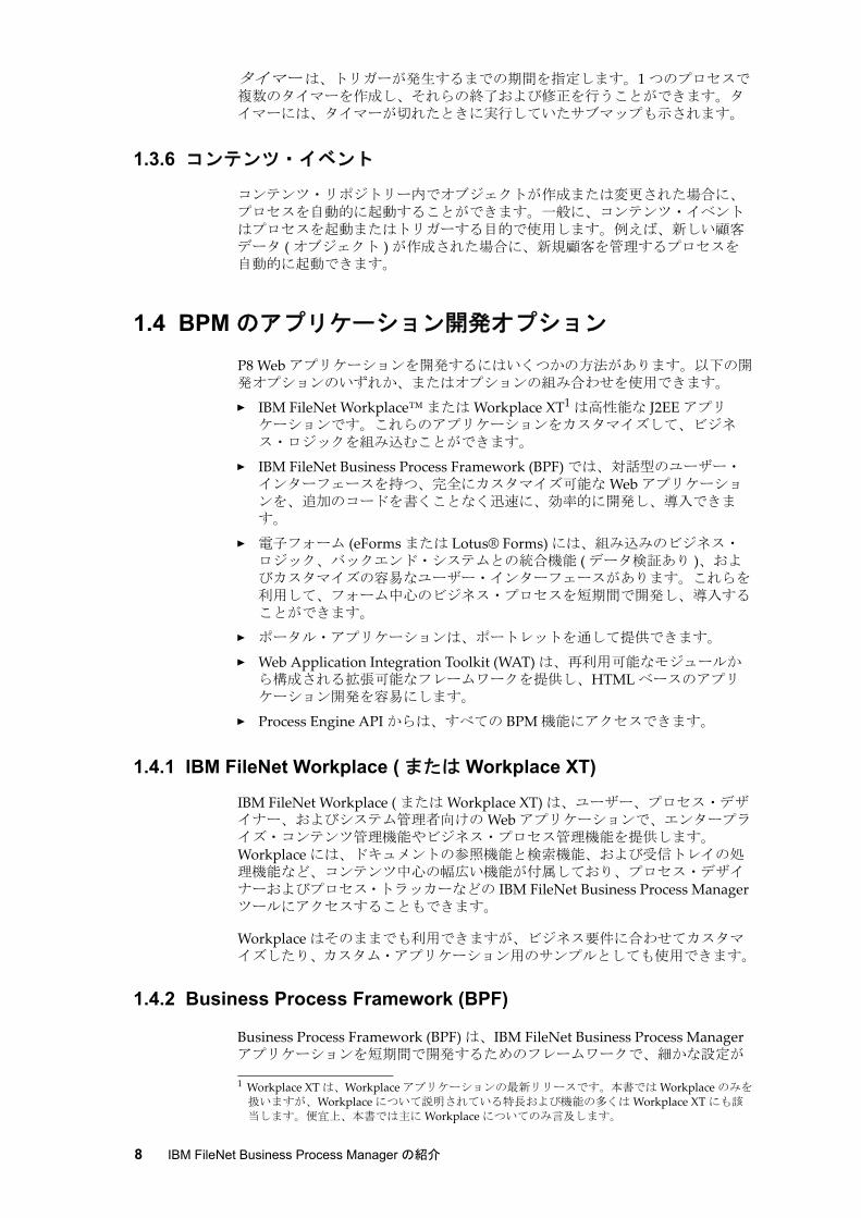
図 1-5 に、各種のビジネス・アクティビティー ( ケースの到着、時間別の到着、製品別のケースなど ) とそれぞれのサービス・レベル・アグリーメント (SLA) パフォーマンスが表示された BAM ダッシュボードを示します。
第 1 章 概要 13
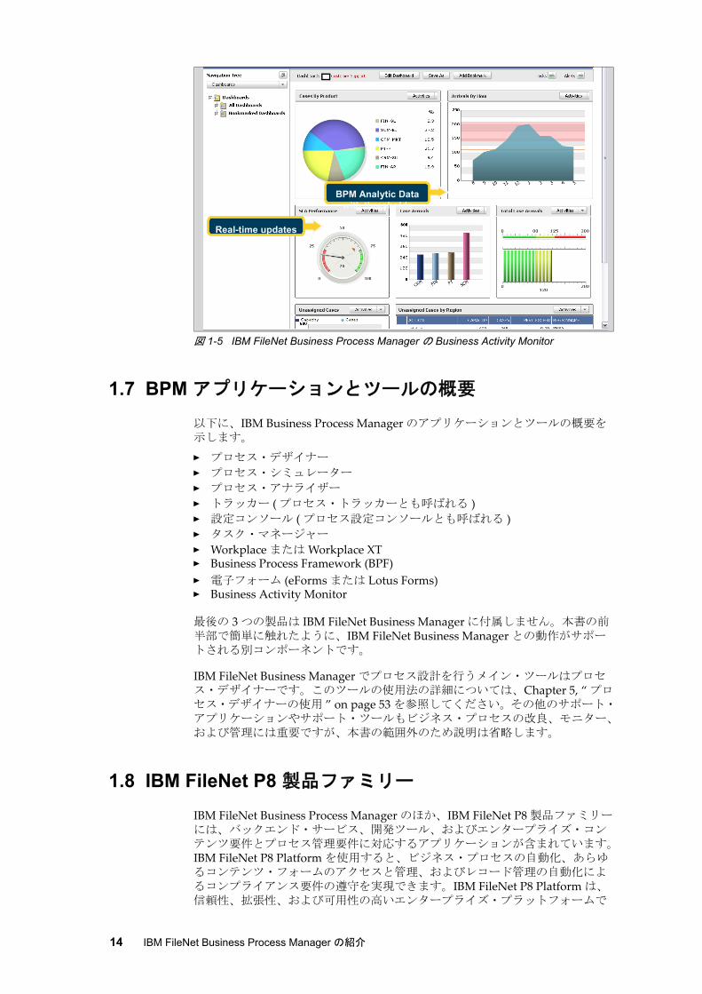
図 1-5 IBM FileNet Business Process Manager の Business Activity Monitor
1.7 BPM アプリケーションとツールの概要
以下に、IBM Business Process Manager のアプリケーションとツールの概要を示します。
� プロセス・デザイナー
� プロセス・シミュレーター
� プロセス・アナライザー
� トラッカー ( プロセス・トラッカーとも呼ばれる )� 設定コンソール ( プロセス設定コンソールとも呼ばれる )� タスク・マネージャー
� Workplace または Workplace XT� Business Process Framework (BPF)� 電子フォーム (eForms または Lotus Forms)� Business Activity Monitor
後の 3 つの製品は IBM FileNet Business Manager に付属しません。本書の前半部で簡単に触れたように、IBM FileNet Business Manager との動作がサポートされる別コンポーネントです。
IBM FileNet Business Manager でプロセス設計を行うメイン・ツールはプロセス・デザイナーです。このツールの使用法の詳細については、Chapter 5, “ プロセス・デザイナーの使用 ” on page 53 を参照してください。その他のサポート・アプリケーションやサポート・ツールもビジネス・プロセスの改良、モニター、および管理には重要ですが、本書の範囲外のため説明は省略します。
1.8 IBM FileNet P8 製品ファミリー
IBM FileNet Business Process Manager のほか、IBM FileNet P8 製品ファミリーには、バックエンド・サービス、開発ツール、およびエンタープライズ・コンテンツ要件とプロセス管理要件に対応するアプリケーションが含まれています。IBM FileNet P8 Platform を使用すると、ビジネス・プロセスの自動化、あらゆるコンテンツ・フォームのアクセスと管理、およびレコード管理の自動化によるコンプライアンス要件の遵守を実現できます。IBM FileNet P8 Platform は、信頼性、拡張性、および可用性の高いエンタープライズ・プラットフォームで
Real-time updates
BPM Analytic Data with thresholds
14 IBM FileNet Business Process Manager の紹介
す。ユーザーはこのプラットフォームを利用することで、情報の取得、格納、管理、セキュリティー保護、および処理を行って、全体的な業務効率を高めることができます。
IBM FileNet P8 Platform はオープンで標準ベースの J2EE アーキテクチャーを採用しており、Microsoft.NET を含む幅広い環境に対応できるよう設計されています。また、多種多様なデータベース、アプリケーション、オペレーティング・システム、ポータル、セキュリティー・フレームワーク、ストレージ、システム管理ツール、および Web サーバー環境もサポートしています。
IBM FileNet P8 製品ファミリーは、主に以下の 3 つのカテゴリーに分類されます。
� コンテンツ
� プロセス
� コンプライアンス
IBM FileNet P8 Platform には、システム管理用のツール・セットも用意されています。
1.8.1 IBM FileNet コンテンツ製品
IBM FileNet P8 製品ファミリーには包括的なエンタープライズ・コンテンツ管理機能があり、コンテンツ管理カテゴリーの製品を多数提供しています。
IBM FileNet Content ManagerIBM FileNet Content Manager は、メタデータおよびコンプライアンスのアクティビティーを安全に制御しながら、細かくカスタマイズされた複雑なコンテンツ・タイプを管理します。IBM FileNet Content Manager の中核となるのは、ビジネス関連のデジタル・アセットを取得、管理、および格納するためのリポジトリー・サービスです。オブジェクト・ストアと呼ばれる複数のリポジトリーを 1 つのシステム内で作成および管理して、ビジネス要件に対応することができます。オブジェクト・ストアの設定では、データベース、ファイル・システム、固定コンテンツ・デバイス (IBM FileNet Image Services リポジトリー、Network Appliance™ SnapLock®、Centera など )、またはこれらのオプションの組み合わせにコンテンツを格納できます。
オブジェクト・ストアには、さまざまなビジネス関連データ ( 自動車保険金請求、顧客の抵当貸し勘定、ビジネス・パートナーに関する情報など ) を格納できます。また、XML ドキュメント、Microsoft Office ドキュメント、Web ページ、写真、音声データ、画像、プロセス定義、テンプレートなど、あらゆるタイプの構造化コンテンツと非構造化コンテンツも格納できます。
Content Federation Services (CFS)CFS では、IBM FileNet のコンテンツ・リポジトリーと IBM FileNet 以外のコンテンツ・リポジトリーを統合して、リポジトリー内のコンテンツを管理できます。
Content Federation Services for Image Services (CFS-IS)Content Federation Services for Image Services (CFS-IS) では、Content Engine リポジトリーと Image Services リポジトリーのコンテンツが自動的に統合されます。CFS-IS を利用すると、Content Engine が Image Services を別のコンテンツ・ストレージ・デバイスとして使用できるようになります。IBM FileNet P8 アプリケーションのユーザーは、既存の Image Services リポジトリーに格納されたコンテンツに対して完全なアクセス権を持ちます。
Workplace で作成されたコンテンツや、Content Engine API を使用してプログラムで作成されたコンテンツは、Image Services の永続的なストレージ・インフラストラクチャーに格納できます。既存の Image Services コンテンツは、Image Services アプリケーションで保存および利用し、さらに IBM FileNet P8
第 1 章 概要 15

製品ファミリー (IBM FileNet Workplace および IBM FileNet Records Manager など ) で再利用することが可能です。その際に、コンテンツが重複したり、既存のアプリケーションが変更されたりすることはありません。どのアプリケーションでも、ドキュメント・コンテンツの場所を気にせずに使用できます。
1.8.2 IBM FileNet プロセス製品
IBM FileNet P8 製品ファミリーには、エンタープライズ・プロセス管理カテゴリーがあります。このカテゴリーで提供される製品には、IBM FileNet Business Process Manager、IBM FileNet Business Process Framework、IBM FileNet eForms、IBM FileNet Business Activity Monitor などがあります。これらの製品の概説については、1.4, “BPM のアプリケーション開発オプション ” on page 8 および 1.6, “BPM プロセスのモニターと分析 ” on page 11 を参照してください。
1.8.3 IBM FileNet コンプライアンス製品
IBM では、電子メールおよびファイル・システム・キャプチャーとレコード・ポリシーおよび BPM プロセスを組み合わせた統合コンプライアンス・フレームワークを提供しています。IBM FileNet P8 製品ファミリーを使用すると、一般ユーザーの手を煩わせずに自動的に、コンプライアンスを強制できます。
コンプライアンス・フレームワークの主力製品は、IBM FileNet Records Manager、IBM FileNet Records Crawler、および IBM FileNet Email Manager の 3 つです。
IBM FileNet Records ManagerIBM FileNet P8 Platform と IBM FileNet P8 Platform と IBM FileNet Records Manager は共同で、単一のシステム・アーキテクチャのソフトウエア・コンポーネントを提供し、一般ユーザーの手を煩わせずに組織が、レコード管理コンプライアンスを実現する手助けをします。IBM FileNet コンプライアンス・フレームワークでは、完全に自動化されたレコードの宣言と分類を ZeroClick と呼びます。IBM FileNet Records Manager を利用すると、レコードの取得、整理、モニター、検索、および保持を容易に行って、規制遵守やレコード管理に関する問題を解決できます。これにより、意思決定や規制要件遵守の向上を図ることができます。
レコードの取得、宣言、および分類は、以下のいずれかの方法で自動的に行うことができます。
� ドキュメント中心 : ドキュメントに基づいてレコードの宣言と分類を行います。ファイルを IBM FileNet P8 コンテンツ・リポジトリー内の特定のフォルダーに保存する際には、システムが一定の基準に応じてそのドキュメントをレコードとして宣言し、分類します。設定によりこのプロセスをユーザーから完全に隠し、レコードの宣言、分類に関する追加のステップや手動決定の必要性を減らせます。
� イベント・ベース : イベントに基づいてレコードの宣言と分類を行います。Web ベースのアプリケーションまたは基幹業務アプリケーションと関連付けられた一定のイベントやトランザクションに従い、事前定義された基準やルール ( トランザクションのタイプまたはトランザクションに関連付けられたメタデータなど ) に基づいて、レコードを自動的に取得および分類することができます。
� プロセス中心 : ビジネス・プロセスに基づいてレコードの宣言と分類を行います。ビジネス・プロセス内の事前決定されたポイントで、事前定義された基準やビジネス・プロセスからのデータに基づいて、レコードの識別、宣言、および正確な分類を自動的に行うことができます。
IBM FileNet Records Manager を利用すると、企業コンプライアンスの手順を施行し、必要なレコードのみを必要な場合にだけ格納し、期限の切れたレコード
16 IBM FileNet Business Process Manager の紹介

を合法的な方法で破棄することができます。これにより、訴訟のリスクが低減され、継続的なビジネスを実現できます。
IBM FileNet Records CrawlerIBM FileNet Records Crawler は、ファイル・システムをスキャンし、指定されたルールに基づいて電子ファイルを取得し、Content Engine に格納するキャプチャー・ツール ( またはアプリケーション ) です。Content Engine では、これらのファイルをレコードとして宣言および分類できます。
IBM FileNet Email ManagerIBM FileNet Email Manager は IBM FileNet Records Crawler に似ていますが、Exchange、Domino®、および Groupwise 電子メール・サーバー上で電子メールを処理する点が異なります。IBM FileNet Email Manager を利用すると、電子メール・コンテンツの取得、整理、モニター、検索、保持、および共有を容易に実行でき、意思決定と規制要件遵守の向上を図ることができます。
1.8.4 IBM FileNet システム管理ツール
IBM FileNet P8 Platform には、システム・コンポーネントとアプリケーション (Process Engine、データベース、IBM FileNet P8 Image Services など ) をモニターするツールがあります。システム管理ツールには、IBM FileNet P8 System Monitor および IBM FileNet System Manager などがあります。
IBM FileNet System Monitor (FSM)IBM FileNet P8 Platform は、システムの可用性が重要となるエンタープライズ規模のミッション・クリティカル・アプリケーションをサポートします。高い可用性と 大限のアップタイムを実現するには、高可用性と災害時回復インフラストラクチャーをサポートするハードウェアとソフトウェアが必要です。さらに、ソフトウェア・オペレーションのあらゆる面をモニターし、あらゆる問題を報告できるシステムも重要となります。
IBM FileNet System Monitor は、ソフトウェア・コンポーネント、アプリケーション・サーバー、データベース、ログ・ファイル、ネットワーク通信、ネットワーク・デバイス、および IBM FileNet ストレージ・ライブラリー全体を含む IBM FileNet P8 環境全体を自動的にモニターします。
IBM FileNet System ManagerIBM FileNet System Manager は、オペレーティング・システムに依存せずに、IBM FileNet P8 製品ファミリー全体のパフォーマンス・データを収集し、配布するツールです。収集されたパフォーマンス・データは、ダッシュボードから利用できます。
第 1 章 概要 17

18 IBM FileNet Business Process Manager の紹介

ëÊ 2 èÕ ソリューションの例
この章では IBM FileNet Business Process Manager を使用して既存のビジネス・プロセスを 適化し、合理化するシナリオを説明します。既存のビジネス・プロセスはほとんどが手作業で行われ、時間がかかり、エラーが発生しがちです。
以下のトピックについて説明します。
� シナリオの背景
� 保険金請求承認プロセス
� 利点のまとめ
2
© Copyright IBM Corp. 2008.All rights reserved. 19

2.1 シナリオの背景
架空の会社、XYZ Corporation を考えます。金融サービスを扱う大企業で、各地のオフィスからなる大規模ネットワークを通じて、幅広い金融商品や金融サービスを提供しています。本社は米国にあり、支社は世界各国にあります。
XYZ Corporation では、ビジネス・プロセスを改善し、保険金請求承認プロセス を効率化しようと考えています。現在のプロセスは部分的に手動で時間がかかり、エラーが発生しやすい状態です。
現在のプロセスは、各地のオフィスから提供されるドキュメントに依存しています。署名漏れなどのミスがある場合や、ドキュメントがなかなかオフィスに届かない場合は、保険金請求承認プロセス全体に影響を及ぼします。また、大部分が手動のプロセスのため、請求査定額が保険契約者に支払われるまでに長い時間がかかります。さらに、保険契約者とその請求 ( 未処理または完了済み ) に関するドキュメントをすべて見つけてグループ化するのが難しく、郵便物やメール・ルームの中でフォームが紛失することもあります。このように保険金請求承認プロセスに時間がかかり、エラーが発生しやすいことから、XYZ Corporation の顧客満足度は低く、顧客とマーケット・シェアも失いかねない状態にあります。
これはコンテンツ中心のプロセスで、コンテンツに基づいて意思決定を行う必要があります。このため、IBM FileNet Business Process Manager はこのビジネス・プロセスの合理化に 適なソリューションと言えます。
2.2 保険金請求承認プロセス
まず、XYZ Corporation の保険金請求承認プロセスの仕組みと、IBM FileNet Business Process Manager でこのビジネス・プロセス全体をどう改善できるかについて説明します。
XYZ Corporation の自動車保険に入っている保険契約者が交通事故に巻き込まれ、XYZ Corporation に保険金請求を提出したとします。提出された請求は、承認または拒否されます。請求が承認された場合、保険契約者には自動車の修理代を賄う小切手が支払われ、修理中はレンタカーを利用できます。請求が拒否された場合は、保険契約者にその旨が通知され、支払いは行われません。
20 IBM FileNet Business Process Manager の紹介

図 2-1 に、この請求承認プロセスのビジネス・コンテキスト図を示します。これは、プロセス全体を通したステップ ( 番号付き ) の順序、プロセスに関与する人、このプロセスで使用または処理されるコンテンツ ( 請求パッケージ ) の流れを示しています。
図 2-1 自動車保険金請求プロセスのビジネス・コンテキスト図
顧客が XYZ Corporation に請求を提出した場合、ビジネス・プロセスおよびビジネス手法について以下のような質問が発生します。
� この請求を承認するか拒否するか。
� 請求が拒否された場合、理由は何か。
� 関連ドキュメントを適切な相手にタイミングよくどう渡すか。
� XYZ Corporation が請求の承認または拒否をより効率的かつ正確に決定するのに役立つ要素は何か。
� ビジネス・プロセスの応答時間を短縮するにはどうするか。
IBM FileNet Business Process Manager で効率的なビジネス・プロセス管理手法を使用することは、保険金請求承認プロセスの自動化と合理化に役立ちます。では、このプロセスの各ステージと、BPM がこのビジネス・プロセス全体をどのように改善するかを見てみましょう。
Back OfficeMailroom Clerks
AdjustorsSupervisors
Accounting ClerksFiling Clerks
Front Office CSRs
Field Agents
1.Customer calls and submits a
claim
2. CSR takes information, and sends to head office via fax
4. Field Agent gets the claim package, reviews
it, associates police report and other related
documents, then sends it to Adjustor
6. Supervisor reviewes the claim and either
approves or rejects it. Approved claims go to
Accounting Department for payment
5. Adjustor receives the claim package, reviews it, and either approves or rejects the claim or
escalates it to Supervisor.Approved claims go to
Accounting Department for payment
7. Accounting Clerk gets the
approved claim package and writes a check and sends it to the claimant. The closed file is
then sent for filing.
3. Mailroom Clerk receives the claim via fax, timestamps the claim
package, searches for policy document, gets the name of Field Agent based on location of loss, and sends the claim package to
Field Agent via US mail
8. Filing Clerk gets the closed file and files it.
第 2 章 ソリューションの例 21

図 2-1 に基づいて、請求プロセスを次の論理的なステージに分けます。
� 請求の開始 ( ステップ 1 および 2)
� 事務管理部門のメール・ルーム担当者のタスク ( ステップ 3)
� 請求プロセス ( ステップ 4 から 6)
� 財務管理コントロール ( ステップ 5 の一部からステップ 6 および 7)
2.2.1 請求の開始 ( ステップ 1 および 2)
顧客からの電話がカスタマー・セールス担当者 (CSR) にかかってくると、XYZ Corporation で保険金請求が開始されます。これが図 2-1 のステップ 1 です。顧客 ( つまり請求者 ) は、有効な保険証券を持つ保険契約者でなければなりません。請求者からの電話を受ける CSR ( 便宜上、代理人とも呼ばれます ) には、請求者に関する情報と、事故の発生場所と発生時刻に関する情報を確認する責任があります。代理人は、この情報の追跡に必要なすべてのフォームに記入し、各ドキュメントを処理するためにファックスで XYZ Corporation の事務管理部門に送ります。これが 21 ページの図 2-1 のステップ 2 です。
現在の請求開始プロセスは手動でエラーが発生しやすい状態です。代理人は手書きのフォームと書類に記入する必要があります。ファイリングされたフォームと書類はプロセス開始に不可欠であり、そのコンテンツによってプロセスの進行が決定します。現在の手動プロセスでは、コンテンツは受動的です。代理人はフォームをファイリングし、ファックスで情報を送信して、請求プロセスを手動で開始する必要があります。自動ソリューションでは、コンテンツがビジネス・プロセスの進行において、より能動的な役割を果たします。
BPM テクノロジーによる改善IBM FileNet Business Process Manager のビジネス・プロセスは、さまざまなステージでコンテンツと交信します。IBM FileNet Business Process Manager では、ビジネス・プロセスによってリポジトリー内のコンテンツをモニターおよびサブスクライブできます。新しいコンテンツがリポジトリーに格納されるか、以前のコンテンツが変更されると、ビジネス・プロセスが自動的に起動されます。また、コンテンツをビジネス・プロセスに添付することもできます。これにより、コンテンツがビジネス・プロセスを認識できるようになります。IBM FileNet Business Process Manager を使用すると、コンテンツとプロセスを別個のアイテムとして扱うのではなく、それらを統合して、より効率的で合理化されたビジネス・プロセス管理を実現できます。
代理人は顧客からの電話を受け、事故に関するドキュメント ( 自動車事故の発生場所と発生時刻など ) を作成します。さらに、損害に関するドキュメントをファックスで事務管理部門に送信します。ファックス情報をもとに、受信側では独自のライフ・サイクル・ルールと保持ルールを使用してドキュメントが作成されます。これが承認プロセスに不可欠なコンテンツ です。代理人がドキュメント化した情報によって、保険金請求承認プロセスが開始されます。この入力済みドキュメントは保険金請求承認プロセスを開始するため、このタイプのドキュメントが新規作成された場合は、新しい保険金請求プロセスが自動的に開始されます。初期請求ドキュメントの作成、ドキュメントへの情報入力、事務管理部門へのドキュメントのファックス送信の組み合わせは、保険金請求承認プロセスを開始する主要な要素となります。
プロセスを開始するコンポーネントを特定しました。次に、コンテンツを活用してプロセスを合理化し、ワークフローを 適化します。電子フォーム (eForms) などのコンポーネントを活用すると、請求開始のために代理人が入力する必要のある書類を自動化できます。電子フォームでデータベース検索機能を使用すると、住所、車種とモデル、VIN 番号などの顧客情報を取得できます。
電子フォームでは、顧客番号、保険証券番号、顧客名などの項目を使用して、保険金請求承認プロセスの開始に必要な追加情報を取得することができます。
22 IBM FileNet Business Process Manager の紹介

初期請求ドキュメントは、請求に関する追加の関連ドキュメントと組み合わせて、一緒にコンテンツ・リポジトリーに格納できます。顧客のドキュメントのいずれかを検索して確認する必要がある場合は、同じシステムで 1 つの検索インターフェースを使用して、ファイリングされたすべてのドキュメントを検索できます。IBM FileNet Business Process Manager はコンテンツのステージングとライフ・サイクルを活用し、ビジネス・プロセスのアクティブ・パーツ ( アクティブ・コンテンツ ) を作成します。
使用する BPM 機能このステージで使用する IBM FileNet Business Process Manager の機能は以下のとおりです。
� 電子フォームの入力 (eForms)
� データベース検索
� アクティブ・コンテンツ ( 電子的に入力された請求 )。これにより、新しい保険金請求承認プロセスがトリガーされます。
2.2.2 事務管理部門のメール・ルーム担当者のタスク ( ステップ 3)
XYZ Corporation の事務管理部門は、代理人が請求情報を作成した後で、その請求情報を処理します。代理人が顧客の損害に関する必要な書類を記入すると、情報は事務管理部門に送られます。事務管理部門のメール・ルーム担当は請求情報をファックスで受け取り、請求パッケージにタイム・スタンプを押し、契約書を検索し、事故現場近辺の現場調査員の名前を特定します。 後に、事務管理部門のメール・ルーム担当は請求パッケージを現場調査員に郵送します。これが 21 ページの図 2-1 のステップ 3 です。
BPM テクノロジーによる改善コンテンツはこのプロセス・ステップにおける重要な要因です。顧客と損害に関する情報はドキュメント化して分類する必要があります。請求パッケージは、確認および処理を担当する現場調査員に転送する必要があります。
IBM FileNet Business Process Manager のルーティング 機能を使用すると、コンテンツを他のユーザー、プロセス、またはシステムに容易に送信できます。条件付きルーティング機能を使用すると、請求パッケージを現場調査員に自動送信できるだけでなく、保険契約者や事故現場などのデータに基づいて、請求を処理する適切な 現場調査員を割り当てることができます。IBM FileNet Business Process Manager を使用すると、オフィス間での郵便転送、手作業による検索、現場調査員の割り当てなど、時間のかかる作業が解消されます。データベース検索 機能と Web サービス を使用すると、適切な情報を適切な相手にタイミング良く渡すことができます。
使用する BPM 機能このステージで使用する IBM FileNet Business Process Manager の機能は以下のとおりです。
� ワーク・パケット ( 請求パッケージ ) を適切な相手に送る電子ルーティング
� データベース検索
� タスクの自動化 ( ビジネス・ルールに基づく現場調査員の割り当てなど )� 適切な情報を適切な相手にタイミング良く渡す Web サービス
第 2 章 ソリューションの例 23

2.2.3 請求プロセス ( ステップ 4 から 6)
現場調査員は請求パッケージを受け取ります。現場調査員は請求パッケージを確認し、請求内容に記入漏れや誤りがないかチェックする責任があります。請求プロセスの一部として、現場調査員は顧客の損失に関する関連ドキュメントを収集する必要があります。この関連情報には、目撃者の供述書、事故現場の写真、警察の供述書などが含まれます。現場調査員には、査定担当者のため、関連ドキュメントやコンテンツを入手する責任があります。関連ドキュメントを収集後は、請求に関して作成済みの他のドキュメントと共にファイリングする必要があります。これが 21 ページの図 2-1 のステップ 4 です。
査定担当者に関連ドキュメントを渡す処理が遅れると、保険金請求承認プロセスに遅延や中断が発生します。査定担当者は請求パッケージを受け取ると、パッケージの内容をすべて確認し、請求の承認または拒否を決定します。代わりに、査定担当者からスーパーバイザーに請求がエスカレーションされる場合もあります。承認された請求は、支払いと記録の保管のため経理部門に送られます。これが 21 ページの図 2-1 のステップ 5 です。
査定担当者は、複数の外部システムを利用して、顧客の請求の完了に必要なすべての情報を入手します。請求を処理する現場調査員と協力しながら査定担当者は、関連ドキュメントを使用して、損害の正当性や契約者が受け取る保険金額を判断します。
請求がスーパーバイザーにエスカレーションされると、スーパーバイザーは承認または拒否します。承認された請求は、支払いと記録の保管のため経理部門に送られます。これが 21 ページの図 2-1 のステップ 6 です。
請求プロセスのこのステップは、伝統的な郵便システムに依存して、現場調査員や査定担当者の請求パッケージや損害情報をやり取りするため、遅延の可能性があります。請求処理に必要なその他の情報の取得に外部システムを利用することも、プロセスを遅らせます。必要なドキュメントがすべて揃っても、現場調査員が査定担当者を割り当てなければ、請求プロセスはさらに遅れます。査定担当者の割り当てや、現場調査員、査定担当者の適切な情報の取得が自動化できる、ステップから遅延は解消します。
BPM テクノロジーによる改善IBM FileNet Business Process Manager は現場調査員への初期請求パッケージの配信、後工程の査定担当者のデスクトップへの配信を自動化するメカニズムを提供し、プロセスを合理化します。ファックスで送られたドキュメントの場合、読みにくく、記入漏れや誤りのチェックに数時間かかる場合がありますが、現場調査員はそのような処理をする必要がなくなります。検証は入力時にアプリケーション・レベルで実行されます。そのため、現場調査員は正しいデータと共に作業が割り当てられたことを確信できます。
IBM FileNet Business Process Manager は現場調査員に、コンテンツを提出し、請求フォルダーに添付 するためにメカニズムを提供して、関連ドキュメントの収集を 適化します。請求フォルダーにコンテンツが追加されると、IBM FileNet Business Process Manager は損害に関するドキュメントを特定し、請求に関する全コンテンツが含まれる場所にファイリングします。関連ドキュメントを現場調査員や査定担当者に送る際に、伝統的な郵便システム等のコストのかかる手段は不要になります。
IBM FileNet Business Process Manager では、コンテンツが正しい顧客フォルダーにファイリングされるように、このコンテンツの分類と処理を自動化することもできます。これにより、今後請求が発生した場合にコンテンツを素早く見つけることができ、レコード管理要件やコンプライアンス要件の遵守にも役立ちます。
前述の機能のほか、IBM FileNet Business Process Manager では外部システム、データ・ソース、およびアプリケーションと交信 して、請求処理に必要な情報を入手することもできます。外部システムでは、追加の保険証券、以前に
24 IBM FileNet Business Process Manager の紹介

提出された請求、保留中の請求などの顧客情報を現場調査員や査定担当者に提供できます。
使用する BPM 機能このステージで使用する IBM FileNet Business Process Manager の機能は以下のとおりです。
� ワーク・パケットを適切な相手に迅速に送る電子ルーティング
� データベース検索 ( 既存の保険証券情報および履歴データ )� ドキュメントが添付されたアクティブ・コンテンツ
� フォルダリング ( ドキュメントをフォルダーまたはワーク・パッケージに追加 )
� システム内のコンテンツ検索
� 外部システムおよびデータ・ソースとの交信による適切な処理情報の入手
2.2.4 財務管理コントロール ( ステップ 5 の一部からステップ 6 および 7)
査定担当者は、請求パッケージと関連ドキュメントを検証し、保険金額を決定します。プロセス中に追加された関連ドキュメント、修理見積、メモ、およびアノテーションはすべて、損害額の決定に関係します。さらに、目撃者の供述書と警察の証明書によって、顧客が損害の責任を負うかどうかが判断されます。
請求が拒否された場合は、スーパーバイザーが査定担当者に通知します。査定担当者は現場調査員にこの決定を通知します。拒否理由について概説する通知書が作成され、顧客に送られます。現場調査員は顧客にこの決定を ( 電話または電子メールで ) 通知します。
請求が承認された場合、査定担当者またはスーパーバイザーは経理部門に請求を送ります。経理部門は支払いを生成し、顧客に送金します。顧客に承認の状況と支払いの送金時期を知らせる通知書を作成し、郵送します。この後、経理部門は未来の監査や検索に備えて、支払いに関する情報を、請求と共にアーカイブします。これが 21 ページの図 2-1 のステップ 7 です。
BPM テクノロジーによる改善IBM FileNet Business Process Manager では、電子フォーム、コンテンツ、ビジネス・プロセスを統合して、論理的かつ直観的でユーザーが使いやすいソリューションを作成できます。査定担当者は請求パッケージのコンテンツから、請求金が自動承認の上限の範囲内かどうかを判断します。請求金額が事前に定められた範囲内の場合、査定担当者が請求を自動承認できます。請求金が上限を超えている場合は、査定担当者からスーパーバイザーに請求がエスカレーションされます。請求金が上限を超えている場合、査定担当者はスーパーバイザーにエスカレーションします。スーパーバイザーには請求承認の決定に利用可能な、追加のツールと、権限があります。
IBM FileNet Business Process Manager のルーティング 機能を使用すると、査定担当者からスーパーバイザーへの作業の流れを自動化できます。査定担当者からスーパーバイザーへの作業の流れに対してシームレスに、条件付きのルーティング・ルール を実装できます。査定担当者、または必要であればスーパーバイザーの承認により作業の完了後は、進行はワークフロー内で定義されたパスに従い再開されるか、または作業の開始場所まで戻ります。IBM FileNet Business Process Manager には、一定の時間 (3 日など ) が経過した場合に、管理者など別のユーザーに請求をエスカレーション する機能もあります。
IBM FileNet Business Process Manager では、外部システムおよびプロセスと交信 して、顧客への通知書作成や支払い処理を自動化できます。通知書、請求書、発注書が作成されると、IBM FileNet Business Process Manager は請求に関する他のドキュメントと共にその通知書を 1 箇所に自動的にファイリング します。このため、顧客や請求に関するすべてのコンテンツ・アイテムを容易に見つけることができます。
第 2 章 ソリューションの例 25

使用する BPM 機能このステージで使用する IBM FileNet Business Process Manager の機能は以下のとおりです。
� ワーク・パケットを適切な相手に自動的に送るルーティング機能とルーティング・ルール
� ビジネス・プロセスの待機および再開機能
� タスクの自動化 ( 顧客への通知書の印刷など )
� 外部システムとの交信 ( 小切手印刷用の会計システムとの交信など )
� 関連ドキュメントのコレクションをフォルダーにファイリング ( 請求関連の全ドキュメントを検索しやすいように 1 箇所にファイリングするなど )
2.2.5 保険金請求承認プロセスのワークフロー・プロセス・マップ
IBM FileNet Business Process Manager では、保険金請求承認プロセスを自動化し、簡易化する、ワークフロー・プロセス・マップを作成できます。
図 2-2 に、保険金請求承認プロセスを実行するメイン・ワークフロー・プロセス・マップを示します。
図 2-2 保険金請求承認プロセスのメイン・ワークフロー・プロセス・マップ
請求のケース ( フォルダー ) の作成、現場調査員の割り当て、関連ドキュメントの収集、査定担当者の割り当てなど、請求ケースの設定アクティビティーはワークフロー・サブプロセスにまとめられ、個別のサブマップとして実装されます。図 2-3 に、この請求設定のサブマップを示します。
図 2-3 保険金請求承認プロセスの請求設定ワークフロー・プロセス・サブマップ
ワークフロー・マップとサブマップの作成など、プロセス設計の詳細については、本書の後半の章で説明します。
26 IBM FileNet Business Process Manager の紹介

2.3 利点のまとめ
この保険金請求承認プロセスの例では、IBM FileNet Business Process Manager を利用すると、コンテンツ ( 請求ドキュメント ) を作成し、ビジネス・プロセス ( 保険金請求承認プロセス ) を自動的に開始できることを説明しました。IBM FileNet Business Process Manager では、コンテンツと交信するプロセスを作成し、より価値の高い ( より正確で効率的な ) ソリューションを実現することができます。また、保険金請求承認プロセスの 適化に必要な構造も提供されます。
プロセスを自動化し、別グループへの作業のルーティングを使用すると、作業 (請求パッケージ ) はシームレスに、現場調査員、査定担当者、スーパーバイザー、経理部門の間を移動します。IBM FileNet Business Process Manager は外部システムとも交信するため、保険契約者への通知書の作成と送付を簡単な自動プロセスにすることができます。プロセスの効率性は高まり、エラー発生率は下がります。また、レポート作成、監査、および保存も簡素化されます。
このソリューションの例で取り上げた IBM FileNet Business Process Manager の機能は以下のとおりです。
� 電子フォームのファイリング (eForms (IBM FileNet P8 製品 ) との統合 )
� アクティブ・コンテンツ : 新規請求による新規ビジネス・プロセスの自動トリガー
� アクティブ・コンテンツ : 既存のワーク・パケットへのドキュメント添付 ( 関連ドキュメント )
� ワーク・パケットを適切な相手に迅速に送る電子ルーティング
例 :
– プロセス内のステップの場所に応じて、ワーク・パケット ( 請求パッケージ ) を査定担当者または代理人に送る
– 請求金やその他のルーティング・ルールに基づいてワーク・パケットを送る
– 一定の条件に該当する場合は、ルーティング内でエスカレーションを行う
� ビジネス・プロセスの待機および再開機能
� データベース検索 ( 既存の保険証券情報および履歴データ )
� ドキュメントのフォルダリング、ファイリング、およびフォルダーまたはワーク・パケットへの追加
� システム内の効率的なコンテンツ検索
� タスクの自動化
例 :
– 事故現場に基づいて請求に現場調査員を割り当てる
– ビジネス・ルールに基づいて請求に査定担当者を割り当てる
– 請求状況に関する顧客への通知書を印刷する
� 適切な情報を適切な相手にタイミング良く渡すための Web サービス、外部システムおよびデータ・ソースとの交信
第 2 章 ソリューションの例 27

28 IBM FileNet Business Process Manager の紹介

ëÊ 3 èÕ システム・アーキテクチャー
この章では、IBM FileNet P8 Platform および IBM FileNet Business Process Manager (BPM) の基本アーキテクチャーについて説明します。IBM FileNet P8 Platform の基礎となる BPM テクノロジーがどのように活用されてビジネスに、コンテンツ中心の自動プロセスが導入されるかを見ていきます。
以下のトピックについて説明します。
� IBM FileNet P8 のコア・エンジン
� 階層化アーキテクチャー
� Process Engine の論理的なビュー
3
© Copyright IBM Corp. 2008.All rights reserved. 29

3.1 IBM FileNet P8 のコア・エンジン
IBM FileNet P8 Platform を構成する主要エンジンは 3 つあります。ここで言うエンジン とは、関連性のある一連の機能を実行するサービスとコンポーネントの集まりを指します。エンジンは多数のパーツで構成されますが、1 つの機能ユニットと見なされます。IBM FileNet P8 環境におけるビジネス・プロセスを定義、開発、および管理する方法を学習する際に各エンジンの複雑な動作を理解する必要はありませんが、それぞれのエンジンが何をするかを知るのは重要です。
IBM FileNet P8 Platform のコア・エンジンは以下の 3 つです。
� Content Engine: Content Engine は、ビジネスに関連する各種の非構造化コンテンツ ( オブジェクトと呼ばれる ) を管理するソフトウェア・サービスを提供します。Content Engine は 1 つ以上のオブジェクト・ストアを管理します。オブジェクト・ストアは、IBM FileNet P8 環境でオブジェクトを格納するリポジトリーです。
� Process Engine: Process Engine コンポーネントでは、自動ビジネス・プロセスの作成、修正、および管理を行うことができます。これらのプロセスは、アプリケーション、社内ユーザー、または外部ユーザー ( パートナーやクライアントなど ) によって実行されます。
� Application Engine: Application Engine は、Workplace Web アプリケーション、Workplace Java アプレット、アプリケーション・プログラミング・インターフェース (API) をホスティングします。Application Engine はプロセスとコンテンツの両方のプレゼンテーション層となります。
図 3-1 に、IBM FileNet P8 の 3 つのエンジンとそれぞれの関係を示します。
図 3-1 IBM FileNet P8 のエンジンの関係
3.2 階層化アーキテクチャー
IBM FileNet Business Process Manager は、コンテンツ中心のプロセス管理と使いやすさを目的として設計されています。 終的な設計目標は、ビジネス・アナリストが組織のビジネス・プロセス管理に容易に使用できる BPM ソリューションを提供することです。ビジネス・アナリストは、IBM FileNet Business Process Manager ソリューションに実装されるプロセスの作成、管理、およびモニターを行う責任があります。
図 3-2 に示すように、IBM FileNet Business Process Manager は 4 層アーキテクチャーとして設計されています。
� クライアント層
� プレゼンテーション層
� ミドルウェア層
� データ層
Application Engine
Process Engine Content Engine
30 IBM FileNet Business Process Manager の紹介

図 3-2 IBM FileNet Business Process Manager の 4 層アーキテクチャー
ほとんどの組織は、階層ごとに異なるサーバーを使用して IBM FileNet Business Process Manager ソリューションをインストールしていますが、より少ないサーバーに階層をまとめることも可能です。
IBM FileNet P8 Platform において機能は、各階層内の他のコンポーネントと同様に、階層化アーキテクチャを使用して提供されます。これらの追加コンポーネントは、コンテンツ管理、電子フォーム、レコード管理、コラボレーション機能など、BPM の重要な機能を提供します。図 3-3 に、IBM FileNet Business Process Manager コンポーネントのアーキテクチャーの概要を示します。
ProcessEngine
Database
Process Engine
Data Tier
Presentation Tier
Client Tier
Middleware Tier
Application Engine
Web Client Application
第 3 章 システム・アーキテクチャー 31

図 3-3 IBM FileNet Business Process Manager コンポーネントのアーキテクチャーの概要
3.2.1 プレゼンテーション層
プレゼンテーション層には、ユーザーとシステムの対話が必要なほとんどの IBM FileNet Business Process Manager アプリケーションとツールが含まれます。API、外部通信、およびカスタム作成のビジネス・ロジックはこの層で提供されます。IBM FileNet P8 では、この層は Application Engine によって実装され、Java Application Server でホスティングされます。
Component IntegratorComponent Integrator を使用すると、プロセスに使用する Java または Java Message Service (JMS) コンポーネントを統合できます。コンポーネントはプロセス設定コンソールに登録され、プロセス・デザイナーで使用可能になります。図 3-4 に、登録済みの Java コンポーネントを示します。
Data Tier
Middleware Tier
Presentation Tier
Java API
WS API
ProcessAnalyzerDatabase
ProcessEngine
DatabaseOLAP
ContentEngine
DatabaseDirectoryService
ContentEngine
ProcessEngine Process
AnalyzerProcess
SimulatorRules
Framework BAM
Component IntegratorWorkplace
BAMDashboard
eForms
FormsManager
Java Connector
JMS Connector
PE Applications
CE Operations
. . .
32 IBM FileNet Business Process Manager の紹介

図 3-4 登録済みの Java コンポーネントと Component Integrator
Process OrchestrationProcess Orchestration は、IBM FileNet Business Process Manager の Web サービス機能を提供します。Process Orchestration を使用すると、プロセスから Web サービス (WS) を開始したり、Web サービス呼び出しを受信したりできます。Process Orchestration 機能の大部分はミドルウェア層で実装されますが、通信部分はプレゼンテーション層で実装されます。
図 3-5 に、Process Orchestration のシステム・アーキテクチャーを示します。
図 3-5 Process Orchestration のシステム・アーキテクチャー
Process Orchestration コンポーネントはタスク・マネージャーから起動でき、すべての入力メッセージを受信する Web サービス・リスナーと、出力メッセージの送信に使用する Web サービス・アダプターで構成されます。
Application Engine
Process Engine
Component Integrator Service Manager
Java adaptor
Java Component
Process Task Manager
Application Engine
Process Engine
Component Integrator Service Manager
WS Adapter
Process Task Manager
WS ListenerIncoming message
Outgoing message
第 3 章 システム・アーキテクチャー 33

3.2.2 ミドルウェア層
図 3-6 に示すように、ミドルウェア層には BPM システムのコアが含まれます。
図 3-6 ミドルウェア層
IBM FileNet BPM のミドルウェア層には、以下のコンポーネントが含まれます。
� Content Engine (CE) カーネル : コアの Content Engine です。
� プロセスの自動起動 : Process Engine システムでプロセス・インスタンスを起動するイベント駆動型コンポーネントです。このコンポーネントは、特定のイベントに応じて特定のプロセス・バージョンを起動するように設定できます。たとえば、ドキュメントをフォルダーにファイリングしたときに、Process Engine システムで特定のプロセスを起動できます。
� Process Engine (PE) カーネル : 実行サブシステムを含む BPM システムのコア・エンジンです。
� 電子メール通知 : 指定したプロセス関連イベントの発生時に、ユーザーに電子メールを自動送信できます。電子メール通知はプロセスの追跡にも使用できます。
� WS API: Process Engine と Content Engine の Web サービス API を提供します。
� ルール・フレームワーク : ルール・エンジンと IBM FileNet Business Process Manager を統合するためのフレームワークを提供します。このフレームワークは詳細に定義されたルール・インターフェースを使用します。ルール・エンジンと統合するには、このインターフェースを実装する必要があります。
� プロセス・アナライザー : 所要時間の算出、トレンドやボトルネックの検出、レポートやグラフの作成により、Process Engine システムに導入されたプロセスの、分析機能を提供します。
� プロセス・シミュレーター : プロセスをシミュレーションし、仮説データまたは履歴データを使用して条件指定 (what-if) のシナリオを実行できます。
� Business Activity Monitor: 他のビジネス・アプリケーションのコンテキストで、進行中のビジネス・プロセスのさまざまな面をほぼリアルタイムでモニターできます。
3.2.3 データ層
図 3-7 に示すように、データ層には BPM データベースとディレクトリー・サービスが含まれます。
Middleware tierWS API
ContentEngine
ProcessEngine
ProcessAnalyzer
ProcessSimulator
RulesFramework
BusinessActivity
Monitoring
ProcessAuto launch
EmailNotification
PE KernelCE Kernel
34 IBM FileNet Business Process Manager の紹介

図 3-7 データ層
データ層には、以下のコンポーネントが含まれます。
� ディレクトリー・サービス : 認証を行います。ディレクトリー・サービス機能には Content Engine からアクセスします。Content Engine は、いくつかの LDAP プロバイダーとシングル・サインオン (SSO) 機能をサポートしています ( 注 : バージョン 4.0 以前のバージョンでは、IBM FileNet Business Process Manager が LDAP ディレクトリーに、直接アクセスしていました )。
� Content Engine データベース : オブジェクト・ストアが含まれます。各オブジェクト・ストアには、コンテンツ自体とコンテンツに関するメタデータが含まれます。
� Process Engine データベース : プロセスの設定と実行中のインスタンスが含まれます。
� プロセス・アナライザー・データベース : 実行中のプロセスの分析データが格納されます。
� プロセス・アナライザー OLAP: プロセス・アナライザー・データベースに格納されたデータの集計が含まれます。この集計データから分析グラフや分析レポートを迅速に作成できます。
3.3 Process Engine (PE) アプリケーションとその他のサポート・アプリケーション
Process Engine アプリケーションはアプレットとして実装され、IBM FileNet P8 Workplace によって Application Engine でホスティングされます。タスク・マネージャーとプロセス・シミュレーター以外のアプリケーションはすべて Process Engine API を使用します。これらの API を使用すると、同様のアプリケーションを作成できます。
図 3-8 に、Process Engine アプリケーションの例を示します。
図 3-8 Process Engine アプリケーションの例
Process Engine アプリケーションには、以下のものが含まれます。
� プロセス・デザイナー : プロセスの作成、修正、および導入に使用します。
� プロセス設定コンソール : IBM FileNet Business Process Manager システムの準備と設定に使用します。
Data Tier
ProcessAnalyzer
OLAP
ProcessEngine
Database
ProcessAnalyzerDatabase
ContentEngine
DatabaseDirectoryService
ProcessDesigner
ProcessConfiguration
Console
ProcessAdministrator
ProcessSimulationDesigner
ProcessSimulationConsole
Tracker
TaskManager
StepProcessors
第 3 章 システム・アーキテクチャー 35

� プロセス・アドミニストレーター : 実行中のプロセスのクエリーと修正に使用します。
� トラッカー ( プロセス・トラッカーとも呼ばれる ): 実行中のプロセスの履歴確認に使用します。
� プロセス・シミュレーション・デザイナー : ビジネス・プロセスのシミュレーション・シナリオの作成に使用します。
� プロセス・シミュレーション・コンソール : シミュレーション・シナリオの管理と実行に使用します。
� タスク・マネージャー (Process Task Manager とも呼ばれる ): Component Integrator を含む、IBM FileNet Business Process Manager システムのさまざまな面の管理に使用します。
� ステップ・プロセッサー : プロセスのステップを完了するためのインターフェースの提供に使用します。IBM FileNet Business Process Manager 環境には、汎用ステップ・プロセッサーが用意されています。eForms と Lotus Forms をステップ・プロセッサーとして使用することもできます。また、Process Engine API を使用して、専用ステップ・プロセッサーを作成することもできます。
3.3.1 プロセス・シミュレーターのシステム・アーキテクチャー
プロセス・シミュレーターには、プロセス・シミュレーション・デザイナー とプロセス・シミュレーション・コンソール からアクセスできます。デザイナーはシミュレーション・シナリオの作成に使用します。シミュレーション・シナリオは Content Engine リポジトリーに保存して、バージョン管理することができます。コンソールはシナリオの管理とシミュレーションの実行に使用します。シミュレーションの実行結果には 2 つあります。シミュレーション分析は、プロセス・アナライザー・データベースに格納され、シミュレーション・オブジェクトは、アニメーション情報を含み、アニメーションの実行用に Content Engine に格納されます。
図 3-9 に、プロセス・シミュレーターのシステム・アーキテクチャーを示します。
図 3-9 プロセス・シミュレーションのシステム・アーキテクチャー
Process Simulator
Scheduler
Publisher
ProcessAnalyzerDatabase
Application Engine
Simulation Console
Simulation Designer
ProcessEngine
ContentEngine
ProcessEngine
Database
ContentEngine
Database
36 IBM FileNet Business Process Manager の紹介

3.3.2 プロセス・アナライザーのシステム・アーキテクチャー
プロセス・アナライザーには、Process Engine データベース内のイベント・ログからイベントを取得するイベント・ディスパッチャー と、イベントを処理するパブリッシャー があります。さらに、パブリッシャーはイベント処理に必要な設定データを取得します。設定情報には、プロセス定義、キュー、イベントに関与するユーザーなどが含まれます。発行処理の 後で、パブリッシャーによってデータベース内のファクト・テーブルが更新されます。
ファクト・テーブル内の統計データは、OLAP キューブの構築に使用します。OLAP キューブは、Microsoft Excel、IBM Cognos Analysis Studio、または IBM Cognos Reports などのレポート・ツールに必要な情報を提供します。
図 3-10 に、プロセス・アナライザーのシステム・アーキテクチャーを示します。
図 3-10 プロセス・アナライザーのシステム・アーキテクチャー
3.3.3 Business Activity Monitor のシステム・アーキテクチャー
Business Activity Monitor (BAM) は、IBM Cognos テクノロジーをベースにしています。BAM は、組み込み接続を介してプロセス・アナライザーからデータを収集します。また、JMS、JDBC™、Web サービス、EAI などの標準接続を介して、外部アプリケーションからデータを収集することもできます。収集されるデータには、生データ ( プロセス・アナライザーの場合と同様 ) とコンテキスト・データがあります。コンテキスト・データは、生データとの関連付けに使用するデータです。たとえば、アカウント番号が含まれた生データ・レコードを使用して、コンテキスト・データに対応するアカウント・ユーザー名を取得できます。
BAM コンポーネントにはインメモリー・ストリーミング機能があり、設定によりインメモリー・ビューと OLAP キューブを生成できます。データのビューを作成でき、さらにルールを適用できます。ルールを使用すると、Key Performance Indicator (KPI) と警告を計算できます。
ProcessAnalyzerDatabase
OLAPProcessEngine
Database
Event Dispatcher
Publisher
Process Analyzer
第 3 章 システム・アーキテクチャー 37

BAM ダッシュボードは、ビューとキューブに格納された情報の表示、KPI に基づくしきい値の作成、警告の設定、しきい値を超えた場合のアクションを実行するよう設定できます。図 3-11 に、BAM ダッシュボードのシステム・アーキテクチャーを示します。
図 3-11 Business Activity Monitor のシステム・アーキテクチャー
3.3.4 Business Process Framework のシステム・アーキテクチャー
Business Process Framework (BPF) は、BPM Web クライアント・アプリケーション開発用の構成可能なフレームワークです。作成された Web クライアントは、HTML、Java Server Pages (JSP™)、JavaScript ページ、その他のオブジェクトを使用した、機能の豊富なインターフェースを提供します。
BPF アプリケーションは、ケース・モデルに基づいて構築されます。たとえば、自動車の保険金請求をケースと考えることができます。生成されたアプリケーションは、Content Engine と Process Engine の両方の API を使用します。アプリケーション・ユーザー・インターフェースはメタデータ駆動型で、ユーザーの要求時に動的に構築されます。ユーザー・インターフェース・レイアウトを記述するメタデータは BPF 設定データベースに格納され、BPF Explorer 設定ツールによって管理されます。
RawData
Views&
Cubes
Application Workbench
ContextData
Rules
Alerts
KPIs
In memory streaming database
BAM Dashboard
Data
Process Analyzer
JMS / JDBC
Web Services
EAI
38 IBM FileNet Business Process Manager の紹介

図 3-12 に、BPF のシステム・アーキテクチャーを示します。
図 3-12 Business Process Framework のシステム・アーキテクチャー
3.4 サービス指向アーキテクチャー (SOA)IBM FileNet Business Process Manager は、ビジネス・プロセスをエンタープライズ・アーキテクチャー内の Web サービスとして実装できる、柔軟性の高いアーキテクチャーを提供します。IBM FileNet Business Process Manager ソリューションは、Web サービスなど標準の統合方式を使用してアプリケーションやシステムとプロセスを接続します。これにより、開発期間を短縮し、より大規模なサービス指向アーキテクチャー (SOA) 構想に対応する新しいビジネス・プロセス管理アプリケーションを作成できます。
IBM FileNet Business Process Manager のプロセスは、Web サービスとして発行され、利用されます。Process Engine は Web サービス・テクノロジーを利用して、プロセス・デザイナーが複数の IBM FileNet Business Process Manager ビジネス・プロセス間で内部的にメッセージ連携を定義したり、IBM FileNet Business Process Manager と他のシステム間で外部的にメッセージ連携を定義したりできるようにします。
Web サービスWeb サービスは、サービス指向アーキテクチャー (SOA) の実装に使用される主要テクノロジーです。Web サービスには SOA の理想的なビルディング・ブロックを形成する特性があります。Web サービスは、一般的なプロトコルと標準規格で構成されています。これらによって、標準形式での Web サービスの発行方法、検出方法、および実装方法が定義されます。
図 3-13 に、基本的な Web サービスの使用法を示します。クライアントは、UDDI レジストリーから Web サービスを検索し、その WSDL を取得します。次に、その Web サービスを呼び出します。UDDI に加え、IBM FileNet Business Process Manager は IBM WebSphere Service Registry and Repository (WSRR) もサポートしています。
BPF Explorer
BPFConfiguration
Database
Application Engine
BPF Web ApplicationWorkplace
ProcessEngine
ContentEngine
ProcessEngine
Database
ContentEngine
Database
第 3 章 システム・アーキテクチャー 39

図 3-13 Web サービスの利用法
Web サービスまたは Web サービス API の存在だけでは SOA を意味しません。単に SOA の作成や統合の基礎となる Web サービスを調整する機能があるだけです。Web サービスを呼び出したり、発行する機能を持ち、より付加価値の高いサービスを作成できることが SOA の重要な面です。IBM FileNet Business Process Manager では、SOA に参加するさまざまな機能が提供されます。
Web サービスの利用外部の Web サービスは、ビジネス・プロセスが Invoke ステップを実行することで利用されます。Invoke ステップは、プロセスを Web サービスとバインドします。ビジネス・プロセスで Web サービスを利用する機能により、既存のアプリケーションからコンポーネントを再利用できるようになります。これは SOA 構築の鍵となります。
Web サービスの発行IBM FileNet Business Process Manager は、プロセスを Web サービスとして発行するための構造を提供します。Web サービスは、Receive ステップを使用して提供されます。また、1 つ以上の Reply ステップ を使用して、Web サービス応答を処理することもできます。
ビジネス・プロセスを Web サービスとして発行すると、IBM FileNet Business Process Manager で定義されたビジネス・プロセスを他のアプリケーションで再利用できるようになります。
IBM FileNet Business Process Manager は、Enterprise Services Bus (ESB) や Web サービス管理システムなどのエンタープライズ・アーキテクチャーとの相互運用が可能です。IBM FileNet Business Process Manager を利用すると、ビジネス・プロセスを自動化して管理し、SOA 環境を構築できます。
3.5 Process Engine の論理的なビュー
IBM FileNet Business Process Manager の中心となるのは Process Engine (PE) です。論理的なビューから、Process Engine はアイソレート・リージョン1 の集
1 アイソレート・リージョンの例については、“ アイソレート・リージョン ” ページの 41 を参照して
ください。
40 IBM FileNet Business Process Manager の紹介

まりと見なすことができます。各リージョンには、キュー、ロスター、およびイベント・ログが含まれます。プロセスは、アイソレート・リージョン内でコンパイルされ、格納されます。各プロセスは、プロセス動作の定義に必要なマップとフィールドの集まりとして定義されます。マップとは、プロセスの完了に必要な有向グラフに一連のステップをまとめたものです。図 3-14 に、Process Engine の論理的なビューを示します。
図 3-14 Process Engine システムの論理的観念
プロセス・サーバープロセス・サーバーは、Process Engine システムのメンバーとして指定される物理的なマシンです。Process Engine システムは Process Engine サーバーのファームであり、1 つ以上のサーバーを持ちます。1 つのプロセス・サーバーは、1 つの Process Engine システムのメンバーとなります。プロセス・サーバーは Process Engine ソフトウェアを実行します。
アイソレート・リージョンアイソレート・リージョン ( 図 3-14 を参照 ) は、Process Engine データベースの論理的な下位区分です。アイソレート・リージョンは、しばしば個別の開発環境、テスト環境、実稼働環境を提供する場合に利用されます。開発者やテスト担当者は、共有するコンピュータ・リソースを効率的に使用でき、また、本質的に異なる作業間に必要な分離環境が提供されます。アイソレート・リージョンは、キュー、ロスター、イベント・ログで構成されます。
キューキュー は、ワーク・アイテムを保持するデータベース構造です。キューには、ユーザー・キュー、ワークフロー・キュー、システム・キューの 3 種類があります。
� ユーザー・キューには、特定のユーザーによる処理待ち状態のワーク・アイテムが保持されます。
� ワークフロー・キューには、特定の参加者ではなくユーザー・グループのメンバーが実行できるワーク・アイテムか、または自動プロセスが実行できるワーク・アイテムが保持されます。
� システム・キューには、Process Engine サーバーによる処理中または処理待ち状態のワーク・アイテムが保持されます。
ロスター は、ワーク・アイテムの現在の場所やその他の情報を格納するデータベース構造です。プロセス・ロスターは、特定のワーク・アイテムの場所を効率的に検出できる Process Engine ソフトウェアを提供します。イベント・
queue
Process Engine System
roster logQueue Roster EventLog
Isolated Region
Isolated Region
queue roster logQueue Roster EventLog
Process Definition
Map
Step
Fields
Process Instance
WorkItem
StepStepStep
Com
pile
第 3 章 システム・アーキテクチャー 41

ログ は、ワーク・アイテム処理に関連するシステム・レベルのイベント情報を格納するデータベース構造です。
プロセス定義プロセス定義 (41 ページの図 3-14 を参照 ) は、ビジネス・プロセスに関する記述です。プロセス定義には、プロセス内で使用されるフィールドやマップなどの情報が含まれます。
マップ は、ビジネス・プロセスの完了に必要なステップの順序を定義したプロセス表現です。ステップ は、詳細に定義された、個別のアクションが実行されるプロセスのステージです。プロセス・マップ上の各ステップは、マップに記述されたビジネス・プロセス内の特定のアクティビティーまたはタスクを表します。ステップ間のルート は、1 つ以上の選択可能な実行パスを示します。フィールド は、プロセス内でデータの保持に使用できるプロパティーです。
プロセス・インスタンスプロセス・インスタンスは、プロセス定義の 1 回の実行に対応します。 例えば、アカウント 120-021 番の自動車保険金請求は、請求プロセス定義のインスタンスであり、「アカウント」フィールドの値は 120-021 となります。プロセス・インスタンスはワーク・アイテムで構成されます。
ワーク・アイテム は、フィールドの集まりで構成される 1 つの作業単位です。ワーク・アイテムはプロセス・マップ内を移動し、プロセスに必要なデータをマップの指示どおりにステップからステップへ渡します。
42 IBM FileNet Business Process Manager の紹介

ëÊ 4 èÕ BPM を使用したプロセス設計
本章では BPM を使用したビジネス・プロセスの設計で使われる基本的な要素と概念について説明します。すべてのトピックについては触れませんが、BPM を使用したワークフロー・プロセスを設計する際に必要な基礎情報はすべて説明します。
以下のトピックについて説明します。
� プロセス設計の基本概念 :– タスク、参加者、およびロール– ワークフローのプロパティー ( ワークフロー・グループと添付 )– ステップ– ルーティング– マイルストーン– 期限– タスクの再割り当て– プロセス投票
� BPM でサポートされるデータ型とシステム関数
� 相互関連プロセス
� 外部システムとの対話
4
注 :
� ここで紹介する例は、19 ページの第 2 章「ソリューションの例」で説明したサンプル・ソリューションに基づきます。まず 19 ページの第 2 章
「ソリューションの例」を読んでから、本章を読み進めてください。
� 本章で基本概念を習得後は、53 ページの第 5 章「プロセス・デザイナーの使用」を読み、プロセス・デザイナーでのビジネス・プロセスの設計方法を理解してください。
� 次の 99 ページの第 6 章「ビジネス・プロセスの実装 : ケース・スタディー」では、ケース・スタディーを使用してビジネス・プロセスを実際に実装する手順を説明します。
© Copyright IBM Corp. 2008.All rights reserved. 43

4.1 プロセス設計の基本概念
IBM FileNet Business Process Manager のプロセス・デザイナーを使用して、ビジネス・ニーズに対応したビジネス・プロセスを設計できます。このツールを使用する前に、ビジネス・プロセスの主な要素を理解しておくことが重要です。
� タスク、参加者、およびロール
� ステップ
� ルーティング
� 期限
� タスクの再割り当て
� プロセス投票
4.1.1 タスク、参加者、およびロール
タスク とは、定義された開始と終了をもつ、組織内外の作業単位です。人、部門、またはシステムにより実行され、ビジネス・プロセスの一部となります。タスクには、「電話をかける人」のように小さく、分割できないものから、「車のレンタル」のように、より複雑なものもあります。
タスクを実行する人を、定義済みタスクの参加者 といいます。ビジネス・プロセスでは、ワークフロー内の 1 つ、または複数のステップで完了する作業が、参加者に割り当てられます。人、グループ、部門、またはシステムが参加者になります。
類似の、または関連のタスクを実行する参加者をロールにまとめられます。ロール は、特定の人またはグループに割り当てられるか、割り当てを予定しているタスクの集合です。ロールが定義されると、参加者が行うすべての作業、および、プロセス内のステップに関連付けられたタスクを識別します。
19 ページの第 2 章「ソリューションの例」で XYZ Corporation のサンプル・ソリューションについて説明しました。このソリューションでは IBM FileNet Business Process Manager を使用して自動車保険金請求承認プロセスを自動化しました。ビジネス・プロセスにおけるタスク、参加者、およびロールをより深く理解するため、この例を再び利用します。
自動車保険金請求承認プロセスの例では、以下のタスクがあります。
� 保険契約者と対話する。
� 保険金請求書を作成して提出する。
� 提出された保険金請求書を審査する。
� 請求に現場調査員を割り当てる。
� 保険金請求の関連ドキュメントを収集する。関連ドキュメントには、警察の証明書、目撃者の証言、および写真などがあります。
� 保険金請求を審査して処理する。
� 保険金請求書を査定担当者に送付する。
� 保険金請求を承認または却下する。
� 保険契約者に請求査定額を支払う。
� 事務管理部門で受け取った保険金請求を分類する。
自動車保険金請求承認プロセスの例には、以下の参加者があります。
� 代理人
� 査定担当者
� 現場調査員
� 経理部門
� 管理部門
� 財務部門
� メール・ルーム
44 IBM FileNet Business Process Manager の紹介

ロールによりタスクが参加者に関連付けられます。この例では、保険金請求承認プロセスに以下のロールがあります。
� 代理人は、保険契約者と対話し、保険金請求書を作成して提出します。
� 査定担当者は、保険金請求書を審査し、請求に現場調査員を割り当てます。
� 現場調査員は、保険金請求の関連ドキュメントを収集します。
� 経理部門は、保険金請求を処理し、請求査定額を保険契約者に払い戻します。
� 管理部門は、管理タスク ( 事務管理部門で受け取った保険金請求の分類など ) を行い、 初の保険金請求書を査定担当者に送付します。
� 財務部門は、保険金請求を承認または却下します。
� メール・ルームは、現場調査員から受け取った保険金請求書を分類して処理します。
したがって XYZ Corporation の例では、従業員と部門にタスクが関連付けられています。また、場合によっては社内外のシステムでタスクを実行する必要があります . このトピックについては後述します。
前述のとおり、タスクとは、開始と終了が定義されている組織内外での作業単位であり、人、部門、またはシステムにより行われます。ビジネス・プロセスの設計時には、まずプロセスにおけるすべてのタスク、参加者、および参加者のロールを特定します。
4.1.2 ワークフローのプロパティー ( ワークフロー・グループと添付 )
ワークフローのプロパティー により、ワークフローの件名とその他の一般プロパティーが指定されます。ワークフローのプロパティーには、ワークフローの任意のステップに適用可能なワークフロー・グループ、添付、データ・フィールドなどがあります。ワークフローのプロパティーは、ワークフロー定義全体に適用されます。
ワークフロー・グループワークフロー・グループ とは、ワークフロー参加者として割り当て可能な 1 つ以上のユーザーまたはグループの集合です。ワークフロー・グループのメンバーは一般に、ビジネス・プロセスにおける 1 つ以上の特定のタスクを実行します ( 請求の査定担当者またはスーパーバイザーなど )。
ワークフローを柔軟に定義するため、1 つのワークフロー・グループに 1 つ以上の特定の参加者を割り当てるか、参加者を後で開始プロセスにおいて割り当てるか、またはビジネス・プロセスを実行中の特定のプロセスで割り当てることができます。このようにワークフロー定義で未指定のワークフロー・グループを使用するテクニックは、特定のタスクの参加者が、ビジネス・プロセスを実行するたびに変わる可能性がある場合に便利です。
システム・ワークフロー・グループBPM には、システム・ワークフロー・グループがあります。F_Originator は特殊なワークフロー・グループであり、ビジネス・プロセスを開始したユーザーの名前を表します。開始時に、システムにより開始ユーザー名がこのワークフロー・グループに割り当てられます。
F_Trackers グループに割り当てられているメンバーはすべて、プロセス・トラッカー・アプリケーションへのアクセス権限を持つワークフローの監視者になります。プロセス実行中にイベントをモニターし、問題解決を支援するために、すべてのワークフロー定義で 1 つ以上のユーザーまたはグループをトラッカーとして割り当てることをお勧めしますが、これは必須ではありません。
第 4 章 BPM を使用したプロセス設計 45

添付添付 は、ワークフローのステップを完了するために参加者が使用する情報へのリンクです。Process Engine のマニュアル等では添付のリンクする特定アイテムを、ターゲットと呼びます。 も一般的なターゲットはオブジェクト・ストア内のドキュメントですが、ドキュメント配列、保存済み検索、フォルダー、URL、または共有ディスク上のファイルもターゲットとして指定できます。
ワークフロー定義プロパティーの一部として添付を定義し、次に各ステップで使用する添付を指定します。
添付を開始添付 として指定できます。開始添付が指定されると、ワークフローの開始に使用されたドキュメントが、選択された添付として割り当てられます。ワークフロー定義は開始添付を 1 つだけ持ちます。
4.1.3 ステップ
ステップ とは、特定のビジネス・アクティビティーまたはシステム・アクティビティーを表します。各ステップでは、タスクを実行する参加者 ( 個人、グループ、およびシステム ) を割り当てることができます。
ビジネス・プロセスは、一連の完了すべきステップで構成されます。ビジネス・プロセス内でタスクや参加者から、実際にどのような特定のステップを作るかは、ビジネス・プロセス・アプリケーションにおいて、何がロジカルで、必要性があり、便利かによります。
保険金請求承認の例では、保険金請求承認プロセスで特定された各タスクに対応するステップを設計できます。複雑なタスクの場合は、タスクを複数のサブタスク、つまり複数のステップに分割できます。
4.1.4 ルーティング
ルーティング により、ビジネス・プロセスにおけるステップの実行順序が指定されます。ルートは、2 つのステップ間のパスを表し、ステップの処理順序を定義します。ビジネス・プロセスの 初と 後のステップを除くその他のすべてのステップには、1 対多のインバウンド・ルートと 1 対多のアウトバウンド・ルートを指定できます。
ビジネス・プロセスではルーティング・オプションと応答を定義できます。ルーティング・オプションは、ステップが完了した時点で評価され、ビジネス・プロセスの次のステップを判別します。選択可能な応答のリストをステップごとに定義できます。これにより、ステップで完了した作業の一部として参加者が応答を選択できます。参加者が選択する応答により、ビジネス・プロセスの次のステップも決定されます。例えば、参加者が保険金請求を承認した (承認応答を選択した ) 場合、ビジネス・プロセスでは残りの作業を完了するため承認ルートが使用されます。参加者が保険金請求を拒否した場合は、別のルートが使用されます。
ルーティング・オプションと応答をビジネス・プロセスに組み込むには次の 3 つの方法があります。
� 単一 ( 線形 ) ルーティング
� 条件付きルーティング
� 並行ルーティング
単一ルーティングは、作業が 1 つのパスに沿ってのみ行われる、ビジネスプロセス内のルートを表します。ワークフローでは 1 つのステップがアクティブになります。ステップに対して 1 つ以上のアウトバウンド・ルートが定義されていることがありますが、アクティブにできるステップは一度に 1 つだけです。
46 IBM FileNet Business Process Manager の紹介

条件付きルーティングでは、ルート上に条件を指定できます。条件は、参加者からの応答またはデータ式の評価結果に基づいて設定できます。式が true と評価された場合は、そのルートが使用されます。応答とデータ・フィールドを組み合わせて式にすることもできます。
複数のステップに同時に分岐して、ビジネス・プロセスでこれらのステップを並行して処理することができます。並行して処理できるステップは、相互に依存していないステップです。1 つのステップに複数のアウトバウンド並行ルートを指定できます。このように指定すると、複数の並行ステップが実行されることになります。すべての並行ステップが完了すると、これらのステップからのアウトバウンド・ルートがすべて コレクター・ステップでマージされ、コレクター・ステップからビジネス・プロセスが続行されます。コレクター・ステップとは、並行ルートを 1 つのステップにまとめる特殊なステップです。複数のパスでの処理によりデータ値が異なる場合、どの値をコレクション・ステップの結果とするかは、マージ・オプションによって決まります。
保険金請求承認の例での各種ルートの使用法を説明します。次の 2 つのステップがあります。
� ステップ A: 代理人は、保険契約者が起こした交通事故の損害を文書にし、保険金請求書を事務管理部門に提出する。
� ステップ B: 事務管理部門のメール・ルーム担当者は、請求を記録し、タイム・スタンプを追加する。
この 2 つのステップ間のルーティングは単純な単一ルーティングです。ステップ間には 1 つのアクティブなパスがあります。2 番目のステップのタスクをメール・ルーム担当者が行うには、 初のステップのタスクが代理人により完了されている必要があります。
以後同じ例を使用しますが、説明の都合で若干変更し、ステップ B でメール・ルーム担当者がシステムに請求を記録した後、次のステップがあると仮定します。
� ステップ C: 現場調査員が物的損害の評価と報告を行う必要があります。
� ステップ D: 医療審査担当者が、事故による負傷を評価および報告する必要があります。
� ステップ E: 物的損害レポートと負傷レポートが提出されたら、査定担当者が請求額を決定します。
ステップ C と D は相互に依存しない 2 つのステップであるため、並行して処理するように設計できます。すなわち、ステップ B から並行アウトバウンド・ルーティングを使用して、ステップ C とステップ D に並行して進みます。次に、ステップ E へのルーティングの前に 2 つのステップが完了しているようにするため、コレクター・ステップを指定できます。
ルートにより、作業が適切な参加者へ送られ、処理されます。定義されているステップとルートを組み合わせてテンプレートを作成できます。テンプレートは、ビジネス・プロセスを実行するたびに使用されます。
4.1.5 マイルストーン
マイルストーンは、ビジネス・プロセス内の重要な通知ポイントとして定義されます。このポイントではどの参加者が、重要なタスクを記述したメッセージや、保留中または完了済みタスクの通知を受けるかを定義します。
各マイルストーンを 1 つ以上のステップで使用できます。ステータス・メッセージを特定のテキストにするか、または 1 つ以上のデータ・フィールドの値をステータス・メッセージに組み込むことができます。ワークフロー・プロセスがマイルストーンに到達する時点で、ワークフローを開始した参加者とユーザーに対して指定したメッセージを表示できます。
第 4 章 BPM を使用したプロセス設計 47

保険金請求承認の例では、マイルストーンは特に使用しません。
4.1.6 期限
期限 は、ビジネス・プロセスのステップに適用可能な時間に基づく制約です。期限が指定されているステップでは、参加者が指定された期間内にそのステップを完了する必要があります。指定される時刻 ( 期限 ) は、ステップを開始した時刻 ( 参加者がワーク・パケットを受け取った時点 ) からの相対時間です。
期限付きタスクにルーティングされた参加者は、電子メールで保留期限の通知を受け取ることができます。期限に達すると、ステップ参加者とワークフローの監視者に電子メール・メッセージが送信されます ( ステップ参加者へのメッセージには未完了ステップも記述されます )。ユーザーは設定を更新して、種類ごとに電子メール通知をオフにできます。期限が切れた場合、エスカレーションの実行を設定し、スーパーバイザーまたはその他の参加者が実行する特別なエスカレーション・ステップにワーク・パケットをルーティングできます。期限を使用すると、ビジネス・プロセスの制御が強化され、エスカレーション・メカニズムが実現します。
保険金請求承認の例では、次のステップで期限の実装を検討できます。
� ステップ : 査定担当者が現場調査員を割り当てる。
査定担当者が現場調査員を割り当てます。このタスクを適切な時点で行わないと、保険金請求承認プロセス全体に影響を及ぼします。このステップに期限を追加すると、このステップに時間管理機能が追加され、査定担当者の段階で保険金請求承認プロセスが遅れることがありません。査定担当者のスーパーバイザーをワークフローのトラッカーとして設定することもできます。この場合は、スーパーバイザーをワークフローの F_Trackers グループに追加します。期限または通知に達すると、査定担当者とスーパーバイザーの両方に通知されます。また、通知を受け取る利用者が、各種電子メール通知をオフにすることもできます。
ステップで期限が切れ、サブマップが指定されている場合、作業はサブマップの 1 番目のステップにルーティングされます。
もちろん現場調査員の割り当てステップを自動化し、査定担当者が手作業で現場調査員を請求に割り当てるのでなく、事故の発生した場所に基づいてシステムが自動的に現場調査員を割り当てることもできます。この場合、期限は不要です。
期限を適用できるタスクの例として、保険金請求の関連ドキュメントを収集するタスクがあります。参加者がコントロールできない要素があるため、参加者が適切な時点でタスクを完了できないことがありますが、期限のメカニズム (通知電子メールと自動エスカレーションを含む ) では、時間を効果的に管理およびコントロールでき、ステップをより適切な時点で完了できます。
4.1.7 タスクの再割り当て
柔軟かつ制御可能なビジネス・プロセスを実現するため、元の参加者がタスクをステップ内のほかの参加者に動的に再割り当てできるステップを設計できます。特に参加者は、タスクを引き継ぐか、または作業を委任する別の参加者を割り当てることができます。IBM FileNet Business Process Manager のコンテキストでは、ステップ内でタスクを再割り当てする場合、委任と放棄という 2 つのオプションがあります。
� 委任 オプションでは、参加者がタスクを別の参加者に再割り当てします。タスクの完了後、ワーク・パケットがビジネス・プロセスの次のステップに移動する前に、審査のため元の参加者に戻されます。
48 IBM FileNet Business Process Manager の紹介

� 放棄 オプションでは、参加者がタスクを別の参加者に再割り当てします。タスクの完了後は、ビジネス・プロセスの次のステップにワーク・パケットが直接送られます。
ワークフローのユーザー・ステップでは再割り当てを無効にできます。
4.1.8 プロセス投票
システムでビジネス・プロセスの次のステップを判別するために複数の参加者からの入力が必要な場合があります。これはプロセス投票 と呼ばれます。プロセス投票が実装されている場合、それぞれの参加者が投票し、投票結果によってビジネス・プロセスの次のステップが決定します。
次のいずれかの条件に基づくルーティング決定を実装できます。
� すべての参加者が同じ応答を選択する ( すべての参加者が承認する場合など)。
� 1 人の参加者が特定の応答をする (1 人以上の参加者が拒否する場合など )。
� すべての参加者が特定の応答を選択しない ( 誰も拒否しない場合など )。
� 単純多数。過半数の参加者が特定の応答を選択する ( ほとんどの参加者が拒否ではなく承認する場合など )。
XYZ Corporation の保険金請求承認ビジネス・プロセスの例でプロセス投票がどのように適用されるかを検討します ( 説明の都合上、若干、例を変更します)。
保険金請求承認プロセスにおいて、リスクが高い請求 ( 請求額が非常に高い場合など ) と判別されると、保険金請求承認決定タスクがスーパーバイザーにエスカレーションするステップがあるとします。指定されているビジネス・ルールに基づき、複数のリスク管理者が承認の決定を下します。 スーパーバイザーは、リスク評価の経験があるリスク管理者に決定タスクをルーティングします。リスク管理者は請求を審査し、それぞれの管理者が請求を承認または拒否します。この例のビジネス・ルールでは、リスク管理者の過半数の承認が得られる場合、その請求は承認されたものとして判断されます。この場合、プロセス投票の単純多数条件を実装します。
プロセス投票機能により、組織は、構造化されたビジネス・プロセスを維持しながら、協同的な意思決定を実装できます。
4.2 BPM でサポートされるデータ型とシステム関数
IBM FileNet Business Process Manager (BPM) では一連のデータ型がサポートされており、プロセス設計に使用できる強力なシステム関数があります。
4.2.1 サポートされるデータ型
BPM では、次の単純データ型と多重 ( 配列 ) データ型のリテラルと変数がサポートされています。
� Boolean� Float� Integer� String� Time
第 4 章 BPM を使用したプロセス設計 49

4.2.2 システム関数
IBM FileNet Business Process Manager には、あらゆる式で使用できる関数が用意されています。例えば、関数にはデータ型変換関数、システム問い合わせ関数、汎用関数、および時間関数があります。
データ型変換関数BPM ではデータ型の変換がサポートされています。変換は、ストリング変数で明示的に指定する必要があります。データ変換関数には次のものがあります。
� convert(source_exp, type_name)
式のデータ型を変換します。
� numbertostring(num_exp{, num_mask}opt)
指定されているマスクを使用して integer または float を string に変換します。
� timetostring(time_exp{, time_mask}opt)
指定されているマスクを使用して time を string に変換します。
システム問い合わせ関数システム問い合わせ関数には次のものがあります。
� systemtime()
現行のサーバー時刻を戻します。
汎用関数汎用システム関数には次のものがあります。
� if(bool_expr, expr2, expr3)
true の場合に expr2、false の場合に expr3 を返す条件式。
� sizeof(array_id)
配列サイズを戻します。
時間関数時間関数には次のものがあります。
� adddays()
指定された日数を追加します。分数、時間数などに対応した関数もあります。
キュー操作操作とは、特定のキューに関連付けられている特定のタスクを実行するステップ内の関数です。操作とそのパラメーターを定義する際には、一般にプロセス・デザイナー、システム管理者、およびアプリケーション開発者が共同で操作の名前と使用法を決定します。
ワークフロー・キュー、コンポーネント・キュー、およびユーザー・キュー内に操作を作成できます。ワークフロー・キュー、コンポーネント・キュー、およびユーザー・キューについては、“ キュー ” ページの 41 を参照してください。
4.3 相互関連プロセス
組織のビジネス・プロセスは非常に複雑になることがあります。1 つのビジネス・プロセスが、作業を完了するために別のビジネス・プロセスに依存している場合があります。そのビジネス・プロセスが、さらに別のプロセスによって開始されるものであることがあります。相互関連プロセス の概念には、1 つ
50 IBM FileNet Business Process Manager の紹介

のビジネス・プロセスが追加処理を実行するために別のプロセスを開始するという考えがあります。
ビジネス・プロセスを設計する際には、他のビジネス・プロセスのうちどれが既に利用可能で、組み込み、または再利用できるかを理解してください。さらに作成中のビジネス・プロセスを複数の論理的に個別のプロセスに分解し、他のプロセスと共有したり、再利用を促進できます。
保険金請求承認の例では、相互関連プロセスを利用できる領域があります。次のステップについて検討します。
� ステップ A: 代理人は、保険契約者が起こした交通事故の損害を文書にし、保険金請求書を事務管理部門に提出する。
� ステップ B: 事務管理部門のメール・ルーム担当者は、請求を記録し、タイム・スタンプを追加する。
事故が原因で請求者の車が運転不可能になり、請求者の保険で請求処理中および車の修理中におけるレンタカーの費用がカバーされている場合は、請求者にレンタカーを直ちに提供するため、前述の 2 つのステップの間にいくつかの新規ステップを追加できます。
説明のため、この例にレンタカー予約のステップを追加してみます。新規ステップ追加後のビジネス・プロセスは次のようになります。
� ステップ A: 代理人は、保険契約者が起こした交通事故の損害を文書にし、保険金請求書を事務管理部門に提出する。
� ステップ A2 ( 新規ステップ ): 代理人が請求の初回審査を実施する。
� ステップ A3 ( 新規ステップ ): 請求者が、事故のため被保険車両が運転不可能であることを申請し、保険契約でこの状況でのレンタカーが認められている場合、代理人は社内の別の個人、または組織に連絡して請求者のレンタカーの準備を依頼し、レンタカー確認番号を受け取り、確認情報を請求者に渡す。
� ステップ B: 事務管理部門のメール・ルーム担当者は、請求を記録し、タイム・スタンプを追加する。
ステップ A3 では、請求者または社内の個人のためのレンタカー予約に別のグループが関与します。これは、そのグループにより実施される独立したビジネス・プロセスです。既にこのようなプロセスが会社で確立している場合は、保険金請求承認プロセスがこのタスクを実行するためにレンタカー予約プロセスを呼び出すことができます。保険金請求承認プロセスに関与する代理人は、実際のレンタカー予約プロセスを理解しておく必要はありません。代理人は、請求者に関する必要な情報を受け渡し、確認番号を後で受け取るだけです。
保険金請求承認プロセスの設計時にレンタカー予約プロセスがシステム内で作成されていない場合、この別個のプロセスを作成し、保険金請求承認プロセス内で呼び出すことができます。
4.4 外部システムとの対話
IBM FileNet Business Process Manager には、ソリューションの作成とカスタマイズ、外部のシステムおよびプロセスとの統合のためのさまざまなツールが揃っています。ビジネス・プロセスが外部システムと対話するためのオプションには、Component Integrator、Web サービス、および EAI コネクターなどがあります。
4.3, “ 相互関連プロセス ” ページの 50 で説明したレンタカー予約プロセスの場合、この予約プロセスはレンタカー会社が実行し、代理人はこのプロセスを意識しません。レンタカー会社にこのような自動プロセスがある場合、保険金請求承認プロセスは、適切なレンタカー予約を行うために外部プロセスと直接対
第 4 章 BPM を使用したプロセス設計 51

話できます。保険金請求プロセスで必要な処理は、代理人によるレンタカーの承認だけです。承認後に保険金請求プロセスは外部予約プロセスに対し車両の予約を要求し、予約番号を自動的に取得します。
Component Integrator、Web サービス、EAI コネクターなど、どのテクノロジー使用すべきかは、外部システムの実装方法と、外部システムとの交信で保険金請求承認プロセスから何を利用可能かによります。
外部システムとの直接的な交信の詳細については、201 ページの第 7 章「Integration with external systems and services with BPM」を参照してください。
52 IBM FileNet Business Process Manager の紹介

ëÊ 5 èÕ プロセス・デザイナーの使用
この章では、プロセス・デザイナーを使用して、ビジネス・プロセス定義を作成する方法について説明します。
ここでは、以下のトピックについて説明しています。
� プロセス・デザイナーのユーザー・インターフェースの概要
� ワークフロー定義の作成の概要
� ワークフローのプロパティーのセットアップ
� ワークフロー・マップ内でのステップの作成
� プロセス・デザイナーを使用したルートの作成
� 高度なトピック :– ワークフローの継承– デフォルトのシステム・サブマップ– 式ビルダ
プロセス設計の概念については、前章を参照してください。プロセス・デザイナーを使用したケース・スタディーのビジネス・プロセス作成手順については、次章を参照してください。
5
注 : オンライン・ヘルプ ecm_help では、プロセス・デザイナーを使用したワークフロー・プロセスの作成について、詳細な情報が提供されます。ここでは本書の便宜性と完全性を図るため、オンライン・ヘルプから一部を抜粋します。プロセス・デザイナーの使用に関する詳細についてはオンライン・ヘルプを参照してください。
© Copyright IBM Corp. 2008.All rights reserved. 53

5.1 プロセス・デザイナーのユーザー・インターフェースの概要
プロセス・デザイナーは、ビジネス・プロセス定義の作成と変更に使用するグラフィック・ツールです。プロセス・デザイナーは、IBM FileNet Business Process Manager に付属するツールの一つです。
プロセス・デザイナーを使用して、ビジネス・プロセス内の各ステップの仕様を作成できます。仕様には、ステップで作業する参加者、参加者がタスクの実行に使用するインターフェース・アプリケーション ( ステップ・プロセッサーとも呼ぶ )、プロセスに必要な添付 ( ある場合 )、表示、追加、または編集に必要なデータ、参加者が選択可能な応答、ビジネス・プロセス内で選択するルートなどが含まれます。プロセス・デザイナーで設計されたビジネス・プロセスのコンピューター内での表現は、ワークフロー定義 といいます ( プロセス定義ともいう )。
プロセス・デザイナーは、IBM FileNet Workplace XT アプリケーションで「ツール」→「 詳細ツール」→「 プロセス デザイナ」と選択して起動します。図 5-1 を参照してください。
図 5-1 プロセス・デザイナーの Workplace XT からの起動
注 : IBM FileNet Business Process Manager におけるビジネス・プロセスは、単純なワークフローだけを意味しません。ただし本書の執筆上の便宜と、プロセス・デザイナーで使用される用語との一貫性のため、これ以降はワークフロー をビジネス・プロセス と同じ意味で使用します。
54 IBM FileNet Business Process Manager の紹介

また、プロセス・デザイナーは、IBM FileNet Workplace の左側のペインのナビゲーション・バーで「オーサー」→「詳細ツール」→υプロセス デザイナ」と選択して起動することもできます。図 5-2 を参照してください。
図 5-2 プロセス・デザイナーの Workplace からの起動
図 5-3 は、プロセス・デザイナーのユーザー・インターフェースを示しています。このウィンドウは、マップ・ペイン、プロパティー・ペイン、およびステップ・パレット・ペインから構成されます。また、マップ・ペインの上にツールバー・アイコン一式があります。
注 : プロセス・デザイナー・アプリケーションを起動した後は、IBM FileNet Workplace の Internet Explorer® のウィンドウを閉じないで ください。Internet Explorer のウィンドウを閉じると、プロセス・デザイナー・アプリケーションも終了します。
第 5 章 プロセス・デザイナーの使用 55

Figure 5-3 プロセス・デザイナーのユーザー・インターフェース
5.1.1 マップ・ペイン
ビジネス・プロセスは、1 つ以上のワークフロー・マップから構成されます。マップは、プロセス・デザイナーのマップ・ペイン内で作成します。マップ・ペインは、「プロセス デザイナ」ウィンドウ上の左上部に表示されます。図 5-3 を参照してください。このペイン内で、ステップとルートを定義します。必ず 1 つのメイン・マップがあり、またオプションで複数のサブマップがあります。
5.1.2 プロパティー・ペイン
プロパティー・ペインは、「プロセス デザイナ」ウィンドウ上の右上部に表示されます。プロパティー・ペインには、マップ・ペインで選択したステップまたはルートのプロパティーが表示されます。マップ内で 1 つのオブジェクト ( 1 つのステップまたはルート ) を作成する場合は、プロパティー・ペイン内でそのオブジェクトにプロパティーを指定します。構成可能なプロパティーは、選択したステップまたはルートのタイプによって変わります。例えば、選択したオブジェクトが General ステップの場合、ステップ先、必須パラメーター、マイルストーン、期限、および General ステップに固有なその他のオプションを指定することができます。選択したオブジェクトがルートの場合、参加者の対応、フィールド値、およびルーティング条件を指定することができます。
図 5-4 は、LaunchStep 用のプロパティー・ペインを示しています。このステップでは、「全般」タブでのステップの完了方法のユーザーへの提示、「パラメータ」タブでの読み取りおよび書き込み用のパラメーターの選択、「割り当て」タブでのパラメーター値の変更、および「ルーティング」タブでのルーティング情報の指定を行うことができます。
ツールバーのアイコン マップ・ペイン ( ワークフローマップ領域 )
ステップ・パレット・ペイン
プロパティ・ペイン
注 : 本書は、IBM FileNet Business Process Manager のバージョン 4.0 に基づいて記述されています。リリース 4.5 以降では、メニューやツールバーなど一部のユーザー・インターフェースが変更される可能性があります。
56 IBM FileNet Business Process Manager の紹介

図 5-4 プロパティー・ペイン
以降の各セクションで、各種ステップとルーティング用のプロパティー・ペインでのさまざまな設定について説明します。
5.1.3 ステップ・パレット・ペイン
「プロセス デザイナ」インターフェースの左下部にあるステップ・パレット・ペインには、ワークフローでの各種アクティビティーを表す事前定義のステップのコレクションが含まれています。
ステップ・パレットには、以下のパレットが含まれています。
� BPM Palette� CheckPoint Palette� General System Palette� Timer Palette� Web Services Palette� マイ パレット
図 5-5 は、「プロセス デザイナ」内のステップ・パレットのドロップダウン・メニューを示しています。
第 5 章 プロセス・デザイナーの使用 57

図 5-5 「プロセス デザイナ」内のステップ・パレット
BPM Palette「BPM Palette」 ( 図 5-6) には、ワークフローに使用する共通のタイプのステップが含まれています。
「BPM Palette」には、以下のタイプのステップが含まれています。
� General ステップ
� サブマップ・ステップ
� システム・ステップ
� コンポーネント・ステップ
図 5-6 BPM Palette
General ステップは、個人の参加者または参加者グループによって実行される基本的なワークフロー・アクティビティー ( タスク ) の処理に使用します。システム・ステップは、組み込みのシステム関数の呼び出しに使用します。コンポーネント・ステップは、外部アプリケーションの操作の呼び出しに使用します。
ワークフロー・マップを単純化するために、ワークフローを 1 つのメイン・マップとより小さいいくつかのサブマップに分割することができます。メイン・マップからサブマップを呼び出すには、サブマップ・ステップを挿入して、そのステップで呼び出すサブマップを指定します。サブマップでは、他のサブマップを呼び出すことができます。
General System PaletteGeneral System Palette ( 図 5-7) には、システム関数を呼び出すステップが含まれています。
「General System Palette」には、以下のタイプのステップが含まれています。
� Assign� Create� DbExecute� Delay� Log
58 IBM FileNet Business Process Manager の紹介

� Return� TerminateBranch� TerminateProcess� WaitForCondition
図 5-7 General System Palette
これらのシステム関数のすべては、「BPM Palette」で使用できるシステム・ステップ内で直接呼び出すことができます。違いは視覚的な問題です。「BPM Palette」からシステム・ステップを使用する場合、ステップのプロパティーを調べない限り、そのステップによりマップ内で呼び出されるシステム関数は分かりません ( マップ上で表示されるステップに非常に説明的な名前を指定すれば別ですが )。「General System Palette」からステップを使用した場合は、そのステップの実行内容が名前でわかります。
「BPM Palette」のシステム・ステップを使用する利点は、同じステップ内で複数のシステム関数を次々と呼び出すことができることです。このため、例えば 1 つのシステム・ステップで、DbExecute()、Create() を実行した後、TerminateBranch() を実行することができ、これらはすべて、ワークフロー・マップ内で単一のステップとして表示されます。これにより、ワークフロー・マップ全体の外観が単純化されます。
Timer PaletteTimer Palette ( 図 5-8) には、タイマー関数によるワークフロー定義内の各ステップとのやり取りを可能にするステップが含まれています。タイマー関数は、処理時間制限をワークフロー内のステップに指定するために使用します。これは、前に 1 ページの第 1 章「概要」で説明した期限機能とは異なります。 期限は、特定のステップに適用されます。タイマーは、通常一連のステップに適用されます。
「Timer Palette」には、以下のタイプのステップが含まれています。
� BeginTimer� SuspendTimer� ResumeTimer� EndTimer� EndAllTimers
図 5-8 Timer Palette
CheckPoint PaletteCheckPoint Palette ( 図 5-9) には、チェックポイント・システム関数によるワークフロー定義内の各ステップとのやりとりを可能にするステップが含まれています。チェックポイント関数では、ワーク・アイテムのデータ・フィールド値を前の状態にロールバックできるようにする機構が提供されます。また、チェックポイント関数により、ワーク・アイテムの処理をワークフローのある時点から再開することも可能になります。
「CheckPoint Palette」には、以下のタイプのステップが含まれています。
� BeginCheckpoint� RollbackCheckpoint� EndCheckpoint
第 5 章 プロセス・デザイナーの使用 59

図 5-9 CheckPoint Palette
Web Services PaletteWeb Services Palette ( 図 5-10) には、ワークフロー定義による Web サービス・システム関数とのやり取りを可能にするステップが含まれています。このステップでは、Web サービスを呼び出し可能なワークフロー内の箇所、またはステップで Web サービスからの応答を受信可能なワークフロー内の箇所を指定します。
「Web Services Palette」には、以下のタイプのステップが含まれています。
� Invoke� Receive� Reply
図 5-10 Web Services Palette
マイ パレットこのパレットを使用すると、ワークフローの設計時に もよく使用するステップ・タイプの独自のコレクションを作成することができます。例えば、別のワークフロー内で再利用可能なカスタム・ステップを作成した場合は、このカスタム・ステップを「マイ パレット」に ( マップ・ペイン内のワークフロー・マップからドラッグして ) 追加して、後でそれを別のマップに使用することができます。「マイ パレット」は、よく使用されるステップや再利用可能なステップの一時的な保管場所として使用することができます。
ステップごとの設定可能な内容については、後のセクションで説明します。各ステップの実行内容について詳しくは、オンライン・ヘルプを参照してください。
5.1.4 ツールバーのアイコン
プロセス・デザイナーのメニューの下には、一連のアイコン ( 図 5-11) があります。これらは、プロセス・デザイナーの各種機能にアクセスするためのショートカットです。以下に、各アイコンが図 5-11 に表示されている順序でそれらをリストして分類します。
� 新規ワークフロー
� 開く
� 保存--------------------------� FileNet 開く / チェックアウト
� FileNet 追加
� FileNet チェックイン
� FileNet チェックアウトの取り消し
� FileNet 保存--------------------------� ワークフローのプロパティ
� ワークフロー コレクション--------------------------� 切り取り
� コピー
60 IBM FileNet Business Process Manager の紹介

� 貼り付け--------------------------� 印刷--------------------------� ワークフローの確認
� ワークフローの開始 (Launch Workflow)--------------------------
図 5-11 ツールバーのアイコン
「ワークフローのプロパティ」、「ワークフローの確認」、および「ワークフローの開始 (Launch Workflow)」の各アイコンは、ワークフローの作成時に繰り返し使用します。本書のケース・スタディーの作成時にも使用します。
5.2 ワークフロー定義の作成の概要
プロセス・デザイナーを使用して、ワークフロー定義 ( プロセス定義ともいう ) を作成します。先に述べたように、ワークフロー定義では、ビジネス・プロセスを完了するために必要なすべてのアクティビティーを記述します。
ワークフロー定義には、ワークフローのプロパティーとワークフロー・マップが含まれています。ワークフローのプロパティーには、ワークフロー全体に及ぶプロパティーが含まれています。サンプルのワークフローのプロパティーには、ワークフローで使用できるすべてのデータ・フィールド、ワークフローで保持できるすべての可能な添付タイプ、およびワークフローでワーク・アイテムを処理できるすべての参加者が含まれています。ワークフロー・マップには、ステップとルートが含まれています。
ステップごとに、そのステップでワーク・アイテムを処理する実際の参加者、およびシステムまたは参加者による読み取りと書き込みのためにそのステップで使用できるデータ・フィールドを指定します。各ステップには、ステップのタイプに応じてセットアップ可能なその他の設定があります。図 5-12 は、ワークフロー定義を構成する各要素を示しています。
図 5-12 ワークフロー定義 ( プロセス定義ともいう )
ワークフロー定義を作成するには、ワークフローのプロパティーをセットアップして、適切なワークフロー・マップを作成する必要があります。
Workflow Definition (also known as Process Definition)
Map
Step
Fields (also known as workflow properties)
Step
StepStep
Route
Route
Route
第 5 章 プロセス・デザイナーの使用 61

5.3 ワークフローのプロパティーのセットアップ
各ワークフローには、一連のワークフローのプロパティーがあります。ワークフローのプロパティーは、ワークフロー全体に及びますが、プロパティー・ペインには、ワークフロー・マップ上で選択したオブジェクトのプロパティーしか表示されないため、「プロセス デザイナ」ウィンドウのプロパティー・ペインに表示されるプロパティーとは異なります。
ワークフローのプロパティーを設定または表示するには、「プロセス デザイナ」のツールバーで「ワークフローのプロパティ」アイコンをクリックするか、メニューから「表示」→「ワークフローのプロパティ」と選択します。図 5-13 を参照してください。
図 5-13 「ワークフローのプロパティ」の表示と編集
以下のタブが、「ワークフローのプロパティ」ダイアログ・ボックスに表示されます。
� 「全般」タブ
� 「詳細設定」タブ ( ロスター、イベント・ログ、条件 ID、および電子メール通知 )
� 「データフィールド」タブ
� 「添付」タブ
� 「ワークフローグループ」タブ
� 「マップ」タブ
� 「マイルストーン」タブ
� 「Web Services」タブ
「全般」タブ図 5-14 に、「ワークフローのプロパティ」ダイアログ・ボックス内の「全般」タブを示します。
図 5-14 「ワークフローのプロパティ」-「全般」タブ
62 IBM FileNet Business Process Manager の紹介

「全般」タブを使用すると、ベース・ワークフロー、名前、件名、説明、および期限などのワークフローの一般情報を指定できます。
「全般」タブで、以下のフィールドを設定します。
� ベース ワークフロー
新規ワークフロー定義の基となるベース・ワークフローを選択します。新規ワークフロー定義を既存のワークフロー ( ベース・ワークフロー ) を基にして、そのベース・ワークフローで定義されているプロパティーとサブマップを継承できます。
ワークフロー定義をデフォルトの設定値に基づいて作成する場合は、デフォルトの WorkObjectEX をベース・ワークフローとしてそのままにします。ワークフロー定義を前に定義した特定のワークフローに基づいて作成する場合は、「修正」アイコンをクリックして、該当のベース・ワークフローを選択します。
ワークフローの継承の機能について詳しくは、5.6.1, “ ワークフローの継承 ” ページの 92 を参照してください。
� ワークフロー名
ワークフロー定義の名前を入力します。この名前は、ワークフロー定義を Process Engine に移行すると、ワークフローのリスト内に表示されます。ワークフロー定義の名前は、以下のルールに従っている必要があります。
– 名前は、文字で始まっている必要があります。名前には、文字、数字、下線、またはスペースを含められます。
– 名前の 大長は 249 文字です。
– 名前の 初の 2 文字として F_ または 2 つのティルド (~~) 文字を含めてはなりません。
– 名前は、1 つのアイソレート・リージョン内にあるワークフロー定義の中で一意である必要があります。
� 件名
ワークフローの内容を表すタイトルを入力します。この件名は、ワークフローの実行中に、参加者がこのワークフローで処理するワーク・アイテムが存在する場合に、参加者の受信トレイ内に表示されます。
� 説明
ワークフローの説明を入力します。これはオプションのフィールドです。
� 期限
ワークフローを完了するまでの制限時間を分数、時間数、日数、または週数で指定します。この時間のカウントは、ワークフローが開始すると始まります。また、期限になる前にリマインダーの通知を設定できます。これはオプションのフィールドです。
電子メール通知を設定した場合は、ワークフローの監視者はリマインダーの通知を受けます。各参加者がワークフローの期限について通知されるようにするには、ワークフローの個々のステップに期限を設定します。
「詳細設定」タブ図 5-15 に、「ワークフローのプロパティ」ダイアログ・ボックス内の「詳細設定」タブを示します。
第 5 章 プロセス・デザイナーの使用 63

図 5-15 「ワークフローのプロパティ」-「詳細設定」タブ
「詳細設定」タブを使用すると、ロスター、イベント・ログ、条件 ID、および電子メール通知などのワークフローに対する拡張機能を指定できます。
タブ内の以下のフィールドを設定します。
� ロスタ
ワークフローのロスターを選択します。デフォルトのロスターが常に選択されます。
ロスターは、ワークフローの現在の場所 ( ワークフローが現在どのステップにあるか、どのワーク・キューにワーク・アイテムがキューイングされているか ) とワークフローに関するその他の情報を格納するデータベース内の表です。ワークフロー・ロスターにより、Process Engine に特定のワークフローを見つけるための効率的な方法が提供されます。
� イベントログ
イベント・ログを選択します。デフォルトのイベント・ログが常に選択されます。
イベント・ログは、ワーク・アイテムの処理に関連するシステム・レベルのイベントに関する情報が格納されたデータベース内の表です。
� 条件 ID
実行時に特定のワーク・アイテムを識別する式を入力します。この値は、WaitForCondition システム関数によって使用され、特定の待機中のワーク・アイテムを識別します。
ワーク・アイテムが別のワーク・アイテムの完了、または条件のクリアを待機しなければならない場合、WaitForCondition システム関数を使用します。例えば、1 つのメイン・ワークフロー・マップと複数のサブマップがあるとします。メイン・ワークフロー・マップでは、メイン・マップのプロセスを継続するためにサブマップの完了を必要とします。条件 ID を設定すると、サブマップは、その完了に関してメイン・マップと通信が可能になります。
� 電子メール通知を有効にする
電子メール通知を現在のワークフロー定義に対して有効または無効にします。
「データフィールド」タブ図 5-16 に、「ワークフローのプロパティ」ダイアログ・ボックス内の「データフィールド」タブを示します。
64 IBM FileNet Business Process Manager の紹介

図 5-16 「ワークフローのプロパティ」-「データフィールド」タブ
「データフィールド」タブを使用すると、ワークフロー・ステップで使用可能なすべてのデータ・フィールドを定義できます。それぞれのステップの定義時に、どのデータ・フィールドがそのステップのパラメーターであるか、および参加者が値を変更するためにどんなアクセス権を持っているかを指定します。データ・フィールドごとに以下の情報を入力します。
� 名前
データ・フィールドの名前を入力します。
� タイプ
フィールドにデータ型 ( ブール値、浮動小数点、整数、文字列、時間 ) の 1 つを選択します。フィールドに複数の値がある場合は、大括弧 ([]) で示される、各データ型の配列バージョンを選択します。
� マージタイプ
値のマージ方法 ( 必要な場合 ) を指定します。
ワークフローの 1 つのステップでは、複数のタスク ( このステップの後続のタスク ) を並列に実行可能な場合は、複数の送信ルートを持つことができます。このフィールドにより、これらのルートが再度 1 つのステップにマージし戻される際に、同じデータ型の複数のソースからの値を 1 つにマージする方法が指定されます。「マージタイプ」のデフォルト値は「上書き」です。
� 式
このフィールドに初期値を指定します。「文字列」フィールドはブランクにできますが、他のすべてのタイプには初期値が必要です。値は、データ型に一致し、また式の条件を満たす必要があります。図 5-16 内の例では、いくつかの日付フィールドに systemtime() を使用しています。
� 説明
データ・フィールドの説明を記述します。これはオプションのフィールドです。
「添付」タブ図 5-17 に、「ワークフローのプロパティ」ダイアログ・ボックス内の「添付」タブを示します。
第 5 章 プロセス・デザイナーの使用 65

図 5-17 「ワークフローのプロパティ」-「添付」タブ
「添付」タブを使用すると、参加者がワークフロー・ステップで使用する添付を指定できます。「添付」にはドキュメントや URL が含まれます。添付ごとに以下の情報を指定します。
� 名前
新規添付の名前を入力します。
� 配列
添付が複数あるかどうかを指定します。「配列」チェック・ボックスを選択した場合は、添付が複数あることを示します。図 5-17 に示した例の場合、SupportingDocs の「配列」チェック・ボックスを選択しています。これは、このワークフローに複数の関連ドキュメントがあると予想されるためです。
� 値
値を添付に指定します。添付がオブジェクト・ストアまたはライブラリー内のファイルまたはフォルダーの場合は、フィールドをダブルクリックしてそれをリストから選択できます。また、値はブランクのままにできます。これにより、値をワークフローの開始時に割り当てでき、またワークフローの処理中に参加者が割り当てることもできます。
� 説明
添付の説明を入力します。これはオプションのフィールドです。
「ワークフローグループ」タブ図 5-18 に、「ワークフローのプロパティ」ダイアログ・ボックス内の「ワークフローグループ」タブを示します。
図 5-18 「ワークフローのプロパティ」-「ワークフローグループ」タブ
66 IBM FileNet Business Process Manager の紹介

「ワークフローグループ」タブを使用すると、ワークフローの参加者として割り当て可能な個々のユーザーまたはグループを指定できます。ワークフロー・グループごとに以下の情報を指定します。
� 名前
ワークフロー・グループの名前を入力します。
� 参加者
ワークフロー・グループのユーザーを選択します。「修正」をクリックして、ユーザーを選択します。
ワークフロー・グループによってステップが処理される場合、設定でワークフロー・グループを使用する前に、ここで参加者またはグループをワークフロー・グループ内に定義する必要があります。
� 説明
ワークフロー・グループの説明を入力します。これはオプションのフィールドです。
「マップ」タブ図 5-19 に、「ワークフローのプロパティ」ダイアログ・ボックス内の「マップ」タブを示します。
図 5-19 「ワークフローのプロパティ」-「マップ」タブ
「マップ」タブを使用すると、ワークフローで使用するメイン・ワークフロー・マップとサブマップを指定できます。サブマップを作成することによって、より柔軟なモジュール形式のワークフロー定義を作成できます。また、ベース・ワークフローから継承されたマップの動作を再定義できます。例えばデフォルトでは、Terminate サブマップと Malfunction サブマップが提供されています。サブマップと、継承マップを再定義する機能により、ワークフロー・プロセス用のカスタムのアクションと処理を作成できます。
マップごとに以下の情報を定義します。
� 名前
メイン・ワークフロー・マップまたはサブマップの名前を入力します。マップが、ワークフローを開始するメイン・ワークフロー・マップであるかどうかを指定します。ワークフロー・プロセスを起動するメイン・マップは、下矢印アイコンの隣に特別な鉛筆の印を付けて表します。
� 説明
マップの説明を入力します。これはオプションのフィールドです。
マップの横に下矢印アイコンがあれば、それはマップが別のマップから継承されたことを意味します。新規マップを初めから作成した場合は、マップの横にはアイコンが付きません。
図 5-20 は、新規に作成した Claim Verification というサブマップを持つ「マップ」タブを示しています。右上隅の「マップの使用」アイコンをクリックすると、Claim Verification サブマップを呼び出すマップが表示されます。図 5-21 を参照してください。
第 5 章 プロセス・デザイナーの使用 67

図 5-20 Claim Verification サブマップ
図 5-21 Claim Verification サブマップの呼び出し側マップ
「マイルストーン」タブ図 5-22 に、「ワークフローのプロパティ」ダイアログ・ボックス内の「マイルストーン」タブを示します。
図 5-22 「ワークフローのプロパティ」-「マイルストーン」タブ
「マイルストーン」タブを使用すると、マイルストーンをワークフロー内に定義できます。マイルストーンは、ワークフロー・プロセスの進捗状況の追跡に役立ちます。ワークフローがマイルストーンに到達すると、マイルストーン・メッセージがログ・ファイルに書き込まれます。マイルストーン・メッセージは、そのレベルによって、ワークフロー参加者、監視者、およびワークフローを開始したユーザーに表示されます。このメッセージは、テキストにすることも、また 1 つ以上のデータ・フィールドの値を含めることもできます。マイルストーンの 大表示長は 250 文字です。マイルストーンごとに以下の情報を定義します。
� 名前
マイルストーンの名前を入力します。
� レベル
マイルストーンのメッセージ・レベル (1 から 99) を指定します。
� メッセージ
68 IBM FileNet Business Process Manager の紹介

このマイルストーンへの到達時にログに記録されるマイルストーン・メッセージ。実行時の 大表示長は 250 文字です。250 文字を超えた部分は切り捨てられます。
「Web Services」タブ図 5-23 に、「ワークフローのプロパティ」ダイアログ・ボックス内の「Web Services」タブを示します。
図 5-23 「ワークフローのプロパティ」-「Web Services」タブ
「Web Services」タブを使用すると、ワークフロー内で使用する Web サービスを指定できます。Web サービスに以下の情報を設定します。
� 「全般」タブ
Web サービスの呼び出し、または Web サービスの提供用の一般的な設定を入力します。
– 受信 Web Service 添付フォルダ
ワークフローで、受信添付が含まれる Web Services オペレーションを使用する場合は、これらのファイルが保管されるオブジェクト・ストア内のフォルダーを指定します。
– 実行時にメッセージを確認
XML メッセージが Receive ( 受信 ) システム・インストラクションに対する受信データとして受信されるか、または、Reply ( 応答 ) システム・インストラクションの応答メッセージとして受信される場合、実行時の受信時にメッセージを妥当性検査するために適切なスキーマを使用するかどうかを指定します。
– 既存の Web Services オペレーションを確定
このオプションを選択して、ワークフロー定義内の Receive 関数と Reply 関数の中の既存のオペレーションの入力パラメーターと出力パラメーター内で変更が起こらないようにします。
� 「パートナー リンク」タブ
このワークフロー内で使用する Web サービスのパートナー・リンクを指定します。パートナー・リンクは、Invoke 関数の名前と WSDL URL、または Receive 関数の名前とポート定義から構成されます。図 5-24 を参照してください。これらは、Invoke、Receive、または Reply の各システム関数を作成する前に必要です。
第 5 章 プロセス・デザイナーの使用 69

図 5-24 「ワークフローのプロパティ」-「Web Services」->「パートナー リンク」タブ
� 「XML スキーマ」タブ
複合データ用の XML スキーマを Receive 関数または Reply 関数内に指定します。図 5-25 を参照してください。
図 5-25 「ワークフローのプロパティ」-「Web Services」->「XML スキーマ」タブ
� 「XML データ フィールド」タブ
パラメーター・モードの代わりに XML モードを使用する Web Services オペレーションに使用します。また、メッセージなどの用途で XML フィールドを指定するために使用できます。図 5-26 を参照してください。
図 5-26 「ワークフローのプロパティ」-「Web Services」->「XML データ フィールド」タブ
Web サービスとそのセットアップ方法については、本書の後の各章で説明します。
70 IBM FileNet Business Process Manager の紹介

5.4 ワークフロー・マップ内でのステップの作成
ワークフロー定義は、ワークフローのプロパティーとワークフロー・マップから構成されます。ワークフロー・マップは、2 つ以上のステップから構成されます。ワークフロー・マップを作成するには、ワークフロー・プロセスに含まれる各ステップ、および各ステップの順序を指定するルートを定義します。
ワークフロー内の各ステップは、参加者、参加者のグループ、またはシステムによって完了される固有のタスクまたはアクティビティーを表します。プロセス・デザイナーには、異なるタイプのアクティビティーを実行するための多数の事前定義のステップ ( 正確には、ステップのテンプレート ) が含まれています。これらのステップはステップ・パレット内に含まれ、必要に応じてワークフロー・マップに追加できます。「BPM Palette」にワークフロー内で使用される以下の も一般的なステップが含まれていたことを思い出してください。
� General ステップ
� サブマップ・ステップ
� システム・ステップ
� コンポーネント・ステップ
ワークフロー・マップ上には、以下の他の 2 つのステップがあります。
� Launch ステップ ( メイン・ワークフロー・マップ内のデフォルトの 初のステップ )
� Start ステップ ( すべてのサブマップ内のデフォルトの 初のステップ )
図 5-27 に、一部のステップがワークフロー・マップ内でどのように表示されるかを示します。ステップのタイプごとに異なるアイコンのシンボル表現であることに注目してください。
図 5-27 異なるタイプのステップを持つメイン・ワークフロー・マップ
すべてのワークフロー・マップにデフォルトの Launch ステップがあります。このステップは、ワークフローの開始時の 初のステップです。下矢印アイコンのシンボル ( 次のレベルにドリルダウンしているように見えます ) を持つ図 5-27 に示されたサブマップ・ステップでは、アクティビティーを実行するためのサブマップが呼び出されます。電気用プラグのアイコンのシンボル ( 何かにプラグインしているように見えます ) を持つコンポーネント・ステップでは、
Launch ステップ サブマップ・ステップ コンポーネント・ステップ
General ステップ
メイン・ワークフロー・マップ
第 5 章 プロセス・デザイナーの使用 71

アクティビティーを実行するための外部システムまたはサービスが呼び出されます。人のアイコンのシンボル ( 何か人によって処理されるもののように見えます ) を持つ General ステップでは、そのステップでアクティビティーを実行する参加者が必要です。General ステップには、そのステップでアクティビティーを処理する人、または、ものに応じて、その他のアイコンのシンボルがあります。これらのステップの構成については、このセクションの後の方でさらに詳しく説明します。
ステップの追加ステップをワークフロー・マップに追加するには、
1. 「ステップ パレット」ドロップダウン・メニューを使用して、適切なパレットを選択します。これは、通常「BPM Palette」です。
2. パレットからステップのアイコンを選択して、それをマップ・ペインにドラッグします。
また、ユーザーは、ステップをマップのコンテキスト・メニューを使用してマップに追加できます。
ステップの構成ワークフロー・マップに追加したステップを構成するには、
1. ワークフロー・マップ内のステップのアイコンを選択します。
2. そのプロパティーを「プロパティ」ペイン内で編集します。
ステップのタイプに応じて、プロパティーの各種設定を構成できます。 詳細については、このセクションの後半で説明します。
ステップの削除ステップをワークフロー・マップから削除するには、
1. ワークフロー・マップ内のステップのアイコンを右クリックします。
2. コンテキスト・メニューから「削除」を選択します。
メイン・ワークフロー・マップとそのサブマップ内に必ず含まれているデフォルトのステップ (Launch ステップと Start ステップ ) は削除できません。
5.4.1 General ステップ
General ステップは、ワークフロー・マップ内で も頻繁に使用されるステップのタイプです。それぞれの General ステップで、ワーク ( タスク ) を完了すべき参加者に割り当てます。ワークフローがこのステップに移動し ( あるいは、ワーク・アイテムがこのステップに移動し )、参加者がタスクに割り当てられていると、参加者の受信トレイにタスクが表示されます。
General ステップでは、タスクをワーク・キューに割り当てることができます。ワーク・キューにアクセス可能なすべてのユーザーが、タスクを実行できます。ワークをワーク・キューに割り当てると、タスクを個人ユーザーに割り当てるよりも柔軟性が向上します。タスクをどのように割り当てるかは、実際のビジネス手法によって決まります。
General ステップの構成設定の多くが他のタイプのステップにも適用されます。他のタイプのステップに同様のプロパティーを構成する際のリファレンスとしてここで説明する設定を使用してください。
ステップを構成するには、「プロパティ」ペインの「名前」フィールドに名前を入力します。意味のあるわかりやすい名前を指定することをお勧めします。この名前は各ステップのアイコンの下にワークフロー・マップ内に表示され、ステップの実行に関する情報を提供します。
72 IBM FileNet Business Process Manager の紹介

General ステップの他のプロパティーは、以下のタブによって構成できます。
� 「全般」タブ
� 「期限」タブ
� 「パラメータ」タブ
� 「割り当て」タブ
� 「ルーティング」タブ
ルール・エンジンを使用するようにワークフローを構成した場合は、「ルール」タブも表示されます。ルール・エンジンの説明は、本書の範囲を超えています。本書では、ルール・エンジンの構成については説明しません。
「全般」タブ図 5-28 に、General ステップの「プロパティ」ペイン内の「全般」タブを示します。
図 5-28 「プロパティ」ペイン -「全般」タブ
「全般」タブを使用すると、ステップに対する参加者のインストラクション、ステップ先、ステップ・プロセッサーなどのステップに関する一般情報を構成できます。
「全般」タブで、以下のフィールドを設定します。
� インストラクション
参加者がこのステップでタスクを処理する際にユーザー・インターフェース上に表示する指示を入力します。図 5-28 内の例には、「査定担当者の確認」ステップがあります。査定担当者がこのステップでワークを処理する際に、図 5-28 に示すように次の指示を表示します。
添付の請求と関連ドキュメントをレビューして、請求を「承認」または「拒否」してください。
� ステップ先
ステップが参加者またはワーク・キューのいずれに割り当てられるかを選択します。
前述のように、実際のビジネス手法に基づいてワークを参加者、またはキューにアクセス可能なすべてのユーザーがワークを処理できるワーク・キューに割り当てられます。
第 5 章 プロセス・デザイナーの使用 73

ワークをワーク・キューに割り当てるには、「ワーク キュー」を選択し、ドロップダウン・リストから既存のキューを選択します。自動化プロセスがキューにアクセス可能な場合は、自動化プロセスもこのステップでワークを処理できます。
ワークを参加者に割り当てるには、「参加者」を選択します。参加者を追加するには、「参加者」入力ボックスの右上隅の「修正」アイコン ( 鉛筆のシンボルで示されています ) をクリックします。「利用者の選択」ダイアログ・ボックスが表示されます。ワークフロー・グループ、ユーザー、または参加者のグループを選択できます。この選択リスト内に選択するワークフロー・グループが表示されない場合は、まずそれらのワークフロー・グループをワークフローのプロパティーに追加してください。
図 5-29 では 3 つのアイコンを示しています。ステップ先がワーク・キューまたは参加者に割り当てられているか、または割り当てなしの場合は、ワークフロー・マップを読み取りやすいように異なるアイコン表示になります。
図 5-29 General ステップを表すアイコン
図 5-28 内の例では、ワークを参加者の査定担当者というワークフロー・グループに明確に割り当てています。
� 見つからない参加者を無視
ステップ先に「参加者」を選択した場合は、参加者がワークフロー・グループに見つからない場合に、見つからない参加者を無視するかどうかを指定します。このフラグを設定せず、またワークを処理可能な有効な参加者が存在しない場合は、ワークフローはこのステップで停止し、エラーが生成されます。図 5-28 内の例では、見つからない参加者が存在する場合にワークを停止させたいため、チェック・ボックスが選択されていません。
� 利用者特権
ステップ先に「参加者」を選択した場合は、参加者がワークを他の参加者に再割り当てできるかどうか、(「トラッカ」ツールを使用して ) ワークフローの状況を表示できるかどうか、またワークフロー履歴を表示できるかどうかを指定します。図 5-28 内の例では、査定担当者にすべての特権があります。
� ステップ プロセッサ
ステップ・プロセッサーとは、参加者がステップでのタスクの処理時に使用するユーザー・インターフェースです。参加者がワークの処理に使用可能なステップ・プロセッサーのリストから選択します。
「期限」タブ図 5-30 に、General ステップの「プロパティ」ペイン内の「期限」タブを示します。
ステップ先 : ステップ先 : ステップ先 : ワーク・キュー 参加者 割り当てなし
74 IBM FileNet Business Process Manager の紹介

図 5-30 「プロパティ」ペイン -「期限」タブ
時間管理のために、タスクがこのステップで完了されるべき時間の期限を設定できます。また、参加者に期限が近づいていることを知らせるためにリマインダーの通知を設定できます。ワークフローのプロパティーで設定された期限は、ワークフロー・プロセス全体に適用されます。ここで設定した期限は、このステップにのみ適用されます。
前の章で説明したように、参加者に期限の前にタスクを完了させるように強制はできません。しかし、期限を設定することにより、ある程度の時間管理を行うことに役立ちます。参加者が予定どおりにタスクを完了させない場合は、受信トレイ内の参加者が完了させる必要があるタスクの隣に、期限切れを示すアイコンが表示されます。また、ここでエスカレーションの時点を設定して、ワークを管理するスーパーバイザーまたは別の管理グループに通知できます。
「期限」タブで、以下のフィールドを設定します。
� 完了期限
タスクをこのステップで完了させる必要がある時間を指定します。期限に固定された期間を指定するには、 初のオプションを使用します。期限をいつにする必要があるかを判定する式を入力するには、2 番目のオプションを使用します。
ここの例では、「査定担当者の確認」ステップに 1 週間の期限を設定しています。つまり、査定担当者には、タスクがこのステップで査定担当者に割り当てられた時間からタスクを完了させるまでに 1 週間の期間があります。
� メモの送信
期限前の一定期間内に、リマインダーを参加者に送信するかどうかを指定します。
図 5-30 内の例では、タスクの期限の 2 日前に査定担当者にメモを送信するように構成しています。
� 期限サブマップ
期限が切れた場合に、この状況に対処するために期限サブマップをアクティブにできます。
期限サブマップは、期限が切れた場合の状況に対処するために設計した任意のサブマップです。
ステップへの期限の設定はオプションです。期限を設定しなくても、異なるフィールドをいくつか設定することもできます。例えば、「メモの送信」と「期限サブマップ」のフィールドを設定せずに、「完了期限」フィールドを設定できます。
第 5 章 プロセス・デザイナーの使用 75

「パラメータ」タブ図 5-31 に、General ステップの「プロパティ」ペイン内の「パラメータ」タブを示します。
図 5-31 「プロパティ」ペイン -「パラメータ」タブ
このステップの読み取りと書き込みに使用できるオペレーションとパラメーターを指定できます。パラメーターには、データ・フィールド、添付、ワークフロー・グループ、および XML フィールドなどがあります。パラメーター値を使用すると、このステップでタスクを実行したり、タスクの一部として値を更新できます。選択可能なパラメーターのリストがあります。必要なパラメーターが「利用可能なパラメータ」リスト内に表示されない場合は、「ワークフローのプロパティ」に戻ってそれを追加します。また、リストの上の 4 つのアイコンの任意のアイコンにチェック・マークを付けて、どのパラメーターが利用可能なリストに表示されるかを調べます。
「パラメータ」タブで、以下のフィールドを設定します。
� オペレーション
宛先ステップとして割り当てられたワーク・キューに、定義されたオペレーションがある場合は、ここで実行するオペレーションを選択できます。
� パラメータの選択
このステップで使用するパラメーターを選択します。例では、パラメーターは、AccidentDescription、Agency、AgencyPhone、AgentName、CaseFolder、ClaimID などです。これらの情報は、査定担当者にとってこのステップで使用するために重要なものです。
� アクセス権
参加者が選択したパラメーターに対して、読み取り権限、書き込み権限、また読み取りと書き込みの両方の権限のいずれを持つかを指定します。図 5-31 内の例では、査定担当者は CaseFolder フィールドと ClaimID フィールドを読み取れますが更新はできません。その他のほとんどのフィールドについては読み取りも書き込み ( 更新 ) もできます。
� プロンプト
76 IBM FileNet Business Process Manager の紹介

参加者がパラメーターを使って作業する際の説明的なプロンプトを入力します。例えば、査定担当者が AccidentDescription フィールドで作業する場合のプロンプトは次のようになります。
事故の説明
「割り当て」タブ図 5-31 に、General ステップの「プロパティ」ペイン内の「割り当て」タブを示します。
図 5-32 「プロパティ」ペイン -「割り当て」タブ
「割り当て」タブでは、マイルストーン情報の設定、式を使用した値のフィールドへの割り当て、およびステップの実行前 (「実行前」サブタブ内で ) またはステップの完了後 (「完了後」サブタブ内で ) の属性の設定を行えます。
「割り当て」タブで、以下のフィールドを設定します。
� マイルストーン
マイルストーンをステップの完了の前か後に割り当てます。
� フィールド割り当て
値をフィールドに割り当てます。フィールドの値として式を入力できます。
� 属性
属性に名前、タイプ、および値を指定します。属性は、それらが設定されるステップ内にのみ存在します。属性は、そのステップに固有な一時的なパラメーターと同様です。
ステップへの割り当ての設定はオプションです。割り当てを設定しないことも、各フィールドを選択して設定することもできます。例えば、「フィールド割り当て」と「属性」の情報を設定せずに、「マイルストーン」を設定できます。
「ルーティング」タブ図 5-31 に、General ステップの「プロパティ」ペイン内の「ルーティング」タブを示します。
第 5 章 プロセス・デザイナーの使用 77

図 5-33 「プロパティ」ペイン -「ルーティング」タブ
「ルーティング」タブでは、ルーティング応答などのルーティング関連の設定、および受信ルーティングと送信ルーティングの設定を構成します。
「ルーティング」タブで、以下のフィールドを設定します。
� 応答
参加者がこのステップで選択可能な応答のリストを指定します。これらの応答により、現在のステップから次のステップへのルーティングが決定されます。図 5-33 内の例では、「査定担当者の確認」ステップの「ルーティング」タブを示しています。このステップで、査定担当者は、請求を拒否するか、承認するか、またはレビューのためにスーパーバイザーにエスカレーションできます。このため、この例では「承認」、「エスカレート」、および「拒否」の 3 つの応答をステップに入力しています。「応答」入力の右上隅にある上矢印と下矢印を使用して、応答の順序を並べ替えられます。
� 受信ルーティング情報
このステップよりも前で並行ルーティングを使用している場合は、いずれかの時点で並列の各ルートを 1 つの場所に結合するコレクター・ステップを作成する必要があります。現在のステップがコレクター・ステップの場合は、「コレクタステップ」オプションにチェック・マークを付けます。そうでない場合は、チェック・マークを外したままにします。
� 送信ルーティング情報
このステップから発して他のステップに向かう複数のルートが存在する場合は、このフィールドでルートを決定する方法を指定します。以下のオプションのいずれかを選択できます。
– すべての合致条件 : あるルートを取るには、すべての指定した条件が真である必要があります。
– 初の合致条件 : ある条件が真になると、即座にそのルートを取ります。
「送信ルーティング情報」の下には、次の 3 つのオプションがリストされています。
� 承認
� エスカレート
� 拒否
78 IBM FileNet Business Process Manager の紹介
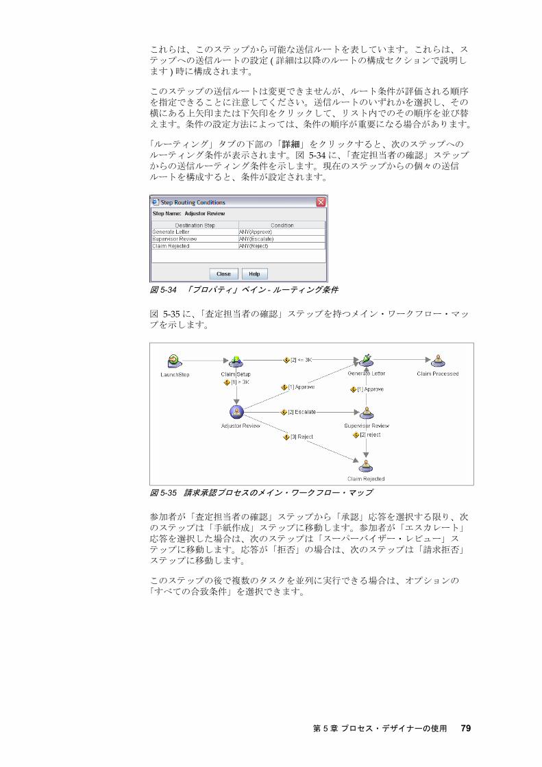
これらは、このステップから可能な送信ルートを表しています。これらは、ステップへの送信ルートの設定 ( 詳細は以降のルートの構成セクションで説明します ) 時に構成されます。
このステップの送信ルートは変更できませんが、ルート条件が評価される順序を指定できることに注意してください。送信ルートのいずれかを選択し、その横にある上矢印または下矢印をクリックして、リスト内でのその順序を並び替えます。条件の設定方法によっては、条件の順序が重要になる場合があります。
「ルーティング」タブの下部の「詳細」をクリックすると、次のステップへのルーティング条件が表示されます。図 5-34 に、「査定担当者の確認」ステップからの送信ルーティング条件を示します。現在のステップからの個々の送信ルートを構成すると、条件が設定されます。
図 5-34 「プロパティ」ペイン - ルーティング条件
図 5-35 に、「査定担当者の確認」ステップを持つメイン・ワークフロー・マップを示します。
図 5-35 請求承認プロセスのメイン・ワークフロー・マップ
参加者が「査定担当者の確認」ステップから「承認」応答を選択する限り、次のステップは「手紙作成」ステップに移動します。参加者が「エスカレート」応答を選択した場合は、次のステップは「スーパーバイザー・レビュー」ステップに移動します。応答が「拒否」の場合は、次のステップは「請求拒否」ステップに移動します。
このステップの後で複数のタスクを並列に実行できる場合は、オプションの「すべての合致条件」を選択できます。
第 5 章 プロセス・デザイナーの使用 79

5.4.2 サブマップ・ステップ
サブマップ・ステップでは、アクティビティーを実行するためのサブマップが呼び出されます。サブマップは、複雑なワークフローをより処理しやすく分割することによって、複雑なワークフローを編成するために役立ちます。さらに、プロセスの一部が複数回 ( 複数のステップがある ) 実行される場合は、サブマップを作成して繰り返されるプロセス部分をカプセル化し、ワークフロー・マップ内で必要な場合はいつでも、サブマップ・ステップにサブマップを呼び出せます。メイン・ワークフロー・マップには、複数のサブマップを持たせられます。サブマップには、他のサブマップも保持できます。
79 ページの図 5-35 は、メイン・ワークフロー・マップの例を示しています。このマップには、「請求設定」という Submap ステップがあります。この Submap ステップにより、図 5-36 に示す「請求設定」サブマップが呼び出されます。サブマップは請求設定のすべてのタスクをカプセル化し、メイン・ワークフロー・マップからタスクの詳細を隠します。
図 5-36 「請求設定」サブマップ
Submap ステップは、以下の各タブによって構成できます。
� 「全般」タブ
� 「属性」タブ
� 「ルーティング」タブ
ルール・エンジンを使用するようにワークフローを構成した場合は、「ルール」タブも表示されます。ルール・エンジンの説明は、本書の範囲を超えています。本書では、ルール・エンジンの構成については説明しません。
「全般」タブ図 5-37 に、サブマップ・ステップの「プロパティ」ペイン内の「全般」タブを示します。
図 5-37 「プロパティ」ペイン - サブマップ・ステップの「全般」タブ
「全般」タブを使用すると、呼び出すサブマップや説明などのステップに関する一般情報を構成できます。
80 IBM FileNet Business Process Manager の紹介

「全般」タブで、以下のフィールドを設定します。
� マップ
ワークフローがこのステップに到達したときに実行するサブマップを選択します。図 5-37 内の例では、「請求設定」サブマップ・ステップのプロパティーを示しています。このサブマップ・ステップでは、「請求設定サブプロセス」サブマップが呼び出されます。サブマップは、ステップとルートに関してメイン・ワークフロー・マップを作成する場合と同様に作成します。
� 説明
サブマップの説明
「属性」タブ図 5-38 に、サブマップ・ステップの「プロパティ」ペイン内の「属性」タブを示します。
図 5-38 「プロパティ」ペイン - サブマップ・ステップの「属性」タブ
属性は、特別な処理のためにサブマップ・ステップ内で使用するように設定できます。各属性は、このステップ内でのみ有効です。属性は、ワークフロー全体で使用できるパラメーターとは異なり、特定のステップでのみ作成および使用されます。
「属性」タブで、使用する属性ごとに以下の情報を設定します。
� 名前
この属性の名前を入力します。
� タイプ
ブール値、浮動小数点、整数、および文字列などの属性タイプを選択します。属性タイプでは配列もサポートされます。
� 値
属性の値を入力します。属性値には「式ビルダ」を使用できないことに注意してください。
サブマップ・ステップの属性の設定はオプションです。ここの例では、何も設定していません。
第 5 章 プロセス・デザイナーの使用 81

「ルーティング」タブ図 5-39 に、Submap ステップ用の「プロパティ」ペイン内の「ルーティング」タブを示します。
図 5-39 「プロパティ」ペイン - Submap ステップ用の「ルーティング」タブ
「ルーティング」タブでは、ステップでの受信ルートおよび送信ルートの処理方法を構成します。
「ルーティング」タブで、以下のフィールドを設定します。
� 受信ルーティング情報
このステップよりも前で並行ルーティングを使用している場合は、いずれかの時点で並列の各ルートを 1 つの場所に結合するコレクター・ステップを作成する必要があります。現在のステップがコレクター・ステップの場合は、「コレクタステップ」オプションにチェック・マークを付けます。そうでない場合は、チェック・マークを外したままにします。
� 送信ルーティング情報
このステップから他のステップに向かう複数のルートが存在する場合、このフィールドでルートの決定方法を指定します。以下のオプションのいずれかを選択できます。
– すべての合致条件 : あるルートを取るには、すべての指定した条件が真である必要があります。
– 初の合致条件 : ある条件が真になると、即座にそのルートを取ります。
図 5-39 に示した例の場合、2 番目のオプションの「 初の合致条件」を選択しています。
「送信ルーティング情報」の下には、次の 2 つのオプションがリストされています。
� > 3K � <= 3K
「ルーティング」タブの下部の「詳細」をクリックすると、このステップから次のステップへ設定されたルーティング条件が表示されます。図 5-40 に、「請求設定」ステップからの送信ルーティング条件を示します。VehicleEstimationAmount が 3000 よりも大きい場合は、「査定担当者の確認」ステップに移動します。見積もり金額が 3000 以下の場合は、「手紙作成」ステップに直接移動します。
82 IBM FileNet Business Process Manager の紹介

図 5-40 「プロパティ」ペイン - サブマップ・ステップのルーティング条件
5.4.3 システム・ステップ
システム・ステップにより、ワークフロー定義内のシステム関数が呼び出されます。システム関数では、特定の関数が実行されます。これらの関数は、以下のように分類できます。
� 一般システム関数 : 一般的なシステム関数を提供します。後述の詳細を参照してください。
� チェックポイント・システム関数 : ワークフロー・プロセスを特定の時点にロールバックできるようにします。
� タイマー : ある時間内に完了する必要のあるワークフロー・プロセスの一部にタイマー制約を提供します。タイマーの開始、終了時間、中断、再開の設定が含まれます。
� Web サービス・システム関数 : Web サービスの呼び出しと受信、呼び出し元への応答などの Web サービスとの通信機能を提供します。
一般システム関数には、以下の関数が含まれます。
� Assign: 値をデータ・フィールドに割り当てます。
� DbExecute: 任意のサポートされたデータベース内でストアード・プロシージャーを実行します。
� Create: 新規ワークフローを開始します。
� Call: サブマップを呼び出します。
� Return: 現在のサブマップを終了して、呼び出し側のマップに戻ります。
� Delay: ワークフローを一定の期間遅延させます。
� Log: イベントをイベント・ログに記録します。
� TerminateBranch: ワークフロー処理の現在の分岐を終了します。
� TerminateProcess: ワークフロー処理の全体を終了します。
� WaitForCondition: 既存の処理をある条件が真になるまで中断します。
チェックポイント・システム関数には、以下の関数が含まれます。
� Checkpoint - BeginCheckpoint� Checkpoint - EndCheckpoint� Checkpoint - RollbackCheckpoint
タイマー・システム関数には、以下の関数が含まれます。
� Timer - BeginTimer� Timer - EndAllTimer� Timer - EndTimer� Timer - ResumeTimer� Timer - SuspendTimer
Web サービス・システム関数には、以下の関数が含まれます。
� Invoke� Receive� Reply
System ステップを構成できる以下の使用可能ないくつかのタブがあります。
第 5 章 プロセス・デザイナーの使用 83

� 「全般」タブ
� 「属性」タブ
� 「ルーティング」タブ
後の 2 つのタブの構成は、General ステップとサブマップ・ステップの構成と同様です。ここでは、「全般」タブについてのみ説明します。
「全般」タブ図 5-41 に、システム・ステップの「プロパティ」ペイン内の「全般」タブを示します。
図 5-41 「プロパティ」ペイン - システム・ステップの「全般」タブ
「全般」タブで、システム・ステップの説明を記述します。システム・ステップで実行するシステム関数ごとに、以下の手順を実行します。
1. 「利用可能な関数」リストから対象のシステム関数を選択します。
2. 右矢印アイコンをクリックします。
3. 「選択された関数」リスト内に表示された対象のシステム関数をダブルクリックします。
4. 追加したシステム関数のタイプに応じて、適切な構成情報を入力します。
さまざまなシステム関数の使い方を学ぶ 良の方法は、プロセス・デザイナーで実際に試してみることでしょう。システム関数の設定は非常に直観的です。ここでは各システム関数の構成については省略します。詳細については、ecm_help を参照してください。
5.4.4 コンポーネント・ステップ
コンポーネント・ステップによりワークフローと、外部のアプリケーション、システム、およびプロセスとの通信が可能になります。カスタム・コンポーネントをインポートして、それらで提供される機能をワークフロー内で使用できます。
図 5-42 に、コンポーネント・ステップを持つ「請求設定」サブマップを示します。
84 IBM FileNet Business Process Manager の紹介

図 5-42 コンポーネント・ステップを持つ「請求設定」サブマップ
コンポーネント・ステップを構成する際に利用可能ないくつかのタブがあります。
� 「全般」タブ
� 「属性」タブ
� 「ルーティング」タブ
後の 2 つのタブの構成は、General ステップ、サブマップ・ステップ、またはシステム・ステップの構成と同様です。ここでは、「全般」タブについてのみ説明します。
「全般」タブ図 5-43 に、コンポーネント・ステップの「プロパティ」ペイン内の「全般」タブを示します。
図 5-43 「プロパティ」ペイン - コンポーネント・ステップの「全般」タブ
「全般」タブを使用すると、このステップで使用するコンポーネントとオペレーションをセットアップできます。
「全般」タブで、以下の情報を設定します。
� 説明
「請求設定」サブマップ
コンポーネント・ステップ
第 5 章 プロセス・デザイナーの使用 85

コンポーネント・ステップの説明を入力します。
� オペレーション
このステップでコンポーネントによって実行される 1 つ以上のオペレーションを追加します。 ここでリストされるオペレーションの順序は、操作の実行の順序です。この順序を並び替えるには、オペレーションを選択して、「オペレーション」入力ボックスの右上隅にある上矢印または下矢印のアイコンをクリックします。削除するには、X アイコンをクリックします。追加するには、右上隅のドキュメント・アイコンをクリックします。
システムで提供されるデフォルトのコンポーネントは、CE_Operarions です。また、このコンポーネントに独自のコンポーネント・オペレーションも追加できます。
例では、コンポーネント・ステップの「ケース作成」が示されています。このステップでは、以下のオペレーションが実行されます。
– createFolder(): 請求ケース用のフォルダーを作成します。– file(): すべての請求に関連するファイルが請求フォルダー内にファイルさ
れます。– searchForOne(): 請求に関連するファイルを検索します。
1 番目と 後のオペレーションは More_Operations コンポーネントによって使用可能であることに注意してください。file() オペレーションは、CE_Operations コンポーネントによって使用可能です。
オペレーションを追加するには、以下の手順を実行します。
a. 「オペレーション」入力ボックスの右上隅にある「追加」( ドキュメント ) アイコンをクリックします。「オペレーション選択」ダイアログ・ボックスが表示されます ( 図 5-44 を参照 )。
b.「コンポーネント」ドロップダウン・リストからコンポーネントを 1 つ選択します。
c. リスト内の 1 つ以上のオペレーションを選択して、「OK」をクリックします。
図 5-44 コンポーネント・ステップのオペレーションの選択
� オペレーションパラメータ
このステップのオペレーションに必要なパラメーターの情報 ( それらの名前、タイプ、および「式」列内の値 ) を入力します。すべてのオペレーションでパラメーターが必要になるわけではありません。パラメーターが必要ないオペレーションもあります。図 5-43 内に示す例では、file() オペレーションだけが、2 つのパラメーターを必要とします。
– sourceDocument– destFolder
86 IBM FileNet Business Process Manager の紹介

両方とも添付タイプのパラメーターです。file() オペレーションにより、請求関連のドキュメント (sourceDocument) が請求フォルダー (destFolder) にファイルされます。
5.4.5 Launch ステップ
Launch ステップは、ビジネス・ワークフロー・プロセス内の 初のステップを表します。Launch ステップの構成は、いくつかの違いを除き、General ステップの構成と同様です。
「全般」タブ内には、ステップ先がありません。また、開始ステップ内では期限を定義できません。「割り当て」タブ内には、「完了後」サブタブしかなく「実行前」サブタブはありません。これは、Launch ステップがワークフロー・プロセス内の 初のステップであるためです。「ルーティング」タブ内には、「受信ルーティング情報」設定はありません。この場合も同様に、Launch ステップが
初のステップであり、このステップへの受信ルートがないためです。
構成について詳しくは、5.4.1, “General ステップ ” ページの 72 を参照してください。
5.4.6 Start ステップ
Start ステップは、サブマップの 初のステップです。Start ステップは、期限を設定できないことを除き、General ステップと同様です。
構成について詳しくは、5.4.1, “General ステップ ” ページの 72 を参照してください。
5.5 プロセス・デザイナーを使用したルートの作成
ルートはビジネス・プロセス内でワークが、あるステップから次のステップに、どのように移動するかを定義します。
ルートの追加ワークフロー・マップ内の 2 つのステップ間にルートを追加するには、以下の手順を実行します。
1. マウス・ポインターを始めのステップの上でルートのシンボルが表示されるまで移動します。
2. このルートを始めのステップから終わりのステップまでドラッグします。
図 5-45 に、これらのステップを示します。
図 5-45 ステップ間にルートの線を引く
ステップ 1: マウス・ポインターを
ステップ 2: このルートを始めのステップから
始めのステップの上に移動します。
終わりのステップまでドラッグします。
ステップ間に生成されたルート
第 5 章 プロセス・デザイナーの使用 87

ルートの構成ワークフロー・マップ内に追加したルートを構成するには、
1. ワークフロー・マップ内のルートを選択します。
2. そのプロパティーを「プロパティ」ペイン内で編集します。
ルートの削除ルートをワークフロー・マップから削除するには、
1. ワークフロー・マップ内のルートを右クリックします。
2. コンテキスト・メニューから「削除」を選択します。
5.5.1 ルートの条件の設定
ルーティング条件を「常に合致」または「条件」のいずれかに設定できます。
現在のステップから次のステップへの送信ルートが 1 つしかない場合、つまり、ワークフロー・プロセスが現在のステップから次のステップへ必ず進む場合は、「常に合致」を選択します。図 5-46 に、メイン・ワークフロー内のルートの例を示します。「開始」ステップから「請求設定」ステップへのルートは、1 つしかありません。このため、この例では「プロパティ」ペイン内で「常に合致」を選択します。「常に合致」を選択した場合は、このルートに他の項目を構成できないことに注目してください。
現在のステップから他のステップに至るルートが複数ある場合は、ルートに「条件」を選択します。ルーティング条件は、参加者が現在のステップ ( このルートの開始元 ) 内で選択した応答に基づくか、またはワークフロー・プロセス内のデータ・フィールドの値に基づいて構成できます。また、応答とデータ・フィールドの両方の組み合わせを使用して、ルーティング条件を設定できます。
データ・フィールド、添付、およびワークフロー・グループなどの条件ルートに使用するデータ・フィールドは、ワークフローのプロパティー内で定義する必要があります。
複数の送信ルートに関しては、システムでどの条件の下で特定のルートが選択されるかを認識できるように、ルートごとに条件を構成します。
88 IBM FileNet Business Process Manager の紹介

図 5-46 「プロパティ」ペイン - ルート構成 : 常に合致
「常に合致」ではなく「条件」で設定されるルートの場合、以下のタブを使用して構成します。
� 「応答」タブ
� 「データフィールド」タブ
「応答」タブ参加者があるステップでタスクを完了した際に、参加者が選択できる応答のリストを設定できます。各応答はこのステップからの送信ルートに対応します。
ルートを応答に基づいて構成するには、「応答」タブ内の以下のフィールドを構成します。
� 条件
以下の条件のオプションのいずれかを選択します。
– ALL: すべての参加者が特定の応答を選択した場合に、true を返します。
– NONE: 参加者のいずれも特定の応答を選択しなかった場合に、true を返します。
– ANY: いずれかの参加者が特定の応答を選択した場合に、true を返します。
– COUNT: 特定の応答を選択した参加者の総数が、特定の値と比較して、等しい、等しくない、より大きい、以上、より少ない、以下、のいずれかの場合に、true を返します。
– 演算子 : COUNT を選択した場合に、カウントを特定の値と比較するために使用する演算子を指定します。「演算子」のオプションには、その値と比較して、「等しい」、「等しくない」、「より大きい」、「以上」、「より少ない」、および「以下」があります。
– 値 : COUNT を選択した場合に、特定の応答を選択した参加者の数に相当する値を指定します。
� 応答
上で指定した条件で処理する特定の応答を選択します。
第 5 章 プロセス・デザイナーの使用 89

条件の設定後に、「挿入」ボタンをクリックして、式を「条件」フィールドに追加します。条件式は手動でも編集できます。ルート用の条件を下部の入力ボックスに挿入した後は、「条件」、「応答」、その他の前述したフィールドで、どの値が選択されているか、または表示されているかは関係ありません。続行する前に、条件が下部に表示されていることを必ず確認してください。図 5-47 を参照してください。
図 5-47 「プロパティ」ペイン -「承認」ルートの「条件付きルーティング」
以下のリストは、「請求承認」メイン・ワークフロー・マップで使用される条件付きルーティングの例です。
� 「査定担当者の確認」ステップを「手紙作成」ステップに接続する「承認」ルートには、以下の条件があります。 ANY(Approve)
これは、「査定担当者の確認」ステップで 1 人の参加者が「承認」応答を選択する限り、「承認」ルートの条件は true を返し、ワークフロー内の次のステップが「手紙作成」ステップに移動することを意味します。
� 「査定担当者の確認」ステップを「スーパーバイザー・レビュー」ステップに接続する「エスカレート」ルートには、以下の条件があります。
ANY(Escalate)
これは、「査定担当者の確認」ステップで 1 人の参加者が「エスカレート」応答を選択する限り、「エスカレート」ルートの条件は true を返し、ワークフロー内の次のステップが「スーパーバイザー・レビュー」ステップに移動することを意味します。
� 同じロジックを使用して、「拒否」ルートには以下の条件があります。
ANY(Reject)
1 人の参加者が「拒否」応答を選択した場合は、次のステップは「請求拒否」ステップに移動します。
� ルートに以下の条件があると仮定します。
COUNT(Approve) >= 2
この場合、2 人以上の参加者が「承認」応答を選択すると即座に、条件が true を返してこのルートが選択されます。
ルートの条件
90 IBM FileNet Business Process Manager の紹介

選択可能な応答のリストは、ルートが開始するステップで定義する必要があることに注意してください。ステップから始まる各ルートでは、いつルートを選択すべきかの条件を設定します。
「データフィールド」タブ参加者によってルート用の条件として選択された応答を使用する代わりに、データ・フィールド内の値を使用して評価のための条件を作成できます。
図 5-48 に、ルート用の条件設定を示します。
図 5-48 「プロパティ」ペイン - ルートの「条件付きルーティング」の「データフィールド」
条件を設定するには、以下のフィールドを使用して、条件の式を構成した後、「挿入」をクリックします。
� フィールド : 条件式内で使用するデータ・フィールドを選択します。
� 演算子 : 条件を評価する演算子を選択します。
� 値 : 条件を評価する値を選択します。
フィールド値を選択および設定した後、必ず「挿入」をクリックしてルート用の条件を追加してください。条件は、複合式を作成するための AND、OR、および括弧を使用して手動で編集できます。
図 5-48 内に示した例には、次の条件があります。
EstimateVehicleAmount>3000
車の修理費用の見積もり額が 3000 より少ない場合に、このルートが選択されることを意味します。
応答とデータ・フィールドの両方の組み合わせルート条件は、参加者の応答とデータ・フィールド値の両方に基づくように設定できます。これを行うには、条件式を手動で編集します。次の式は、データ値と参加者の応答の両方に基づいた条件の例です。
EstimateVehicleAmount>3000 and ANY(Approve)
注 : このステップでタスクを処理する参加者が 1 人しかいない場合は、条件の ANY と ALL は同じになります。
第 5 章 プロセス・デザイナーの使用 91

5.6 高度なトピック
このセクションでは、プロセス・デザイナーを使用したワークフロー定義の作成に関連する、これまでに説明した基本概念を超えるトピックについて説明します。特に、ワークフローの継承とその動作方法、デフォルトのシステム・サブマップとその上書き方法、および「式ビルダ」を使用した、ルートの条件付けまたはパラメーターの割り当て用の各種式の作成について説明します。
5.6.1 ワークフローの継承
ワークフローの継承を有効にすると、既存のワークフロー定義をベース・ワークフローとして選択し、新規ワークフロー定義を継承できます。既存の定義をより高いレベルで活用し、新規ワークフロー定義に伝えられます。
新規ワークフローには、以下のアイテムをベース・ワークフローから継承できます。
� メイン・ワークフロー・マップ
� サブマップ
� 「データフィールド」、「添付」、および「ワークフローグループ」の定義
� ワークフローの期限とメモ
� マイルストーン
� イベントログ
� ロスタ
� 条件 ID� 「パートナー リンク」と「XML スキーマ」
� XML データ フィールド
� 受信 Web Service 添付フォルダ
� 「ルール セット」の名前
� 電子メール通知の設定
継承されたアイテムを上書きするには、新規ワークフロー定義内で再定義します。
いくつかの例を見ていきます。図 5-49 に、Workflow A と Workflow M という 2 つのワークフロー、およびそれらのローカルおよび継承されたワークフローのプロパティーを示します。
図 5-49 Workflow A と M についてのワークフロー継承の流れの階層
Workflow A は、デフォルトのワークフロー定義 WorkObjectEx から継承します。Workflow A には、以下のアイテムが含まれています。
� メイン・ワークフロー・マップ A� サブマップの a1 と a2� データ・フィールドの a1 と a2
注 : 条件ルーティングは慎重に設定してください。あるステップからの送信ルートが複数ある場合に、ルート内の条件のいずれも true を返さない場合は、ワークフローが停止してエラーを生成します。
92 IBM FileNet Business Process Manager の紹介

Workflow M は、Workflow A からのアイテムのいくつかを継承し、その他のものを上書きします。Workflow M には、以下のアイテムが含まれています。
� メイン・ワークフロー・マップ M (Workflow A からのものを上書き )� サブマップ a1* (Workflow A からのものを上書き )� サブマップ a2 (Workflow A から継承 )� サブマップ m1 (Workflow M 用の新規のもの )� データ・フィールドの a1 と a2 (Workflow A から継承 )� データ・フィールド m1 (Workflow M 用の新規のもの )
ここで新規の Workflow R を追加すると、これらの 3 つのワークフローのワークフロー継承の流れの階層は、図 5-50 内に示すようになります。
図 5-50 Workflow A、M、および R についてのワークフロー継承の流れの階層
Workflow R は Workflow M から継承します。Workflow R には、以下のアイテムが含まれています。
� メイン・ワークフロー・マップ M (Workflow M から継承 )� サブマップの a1* と m1 (Workflow M から継承 )� サブマップ a2 (Workflow A から継承 )� サブマップ rm1 (Workflow R 用の新規のもの )� データ・フィールドの a1 と a2 (Workflow A から継承 )� データ・フィールド m1* (Workflow M から継承 )� データ・フィールド r1 (Workflow R 用の新規のもの )
継承が無効にされた場合は、Workflow R には以下のアイテムしか含まれません ( 図 5-51 を参照 )。
� メイン・ワークフロー・マップ R (Workflow R 用の新規のもの )� サブマップ rm1 (Workflow R 用の新規のもの )� データ・フィールド r1 (Workflow R 用の新規のもの )
他のすべての継承されたメイン・マップ、サブマップ、およびデータ・フィールドは、使用できなくなります。
図 5-51 ワークフローの継承の無効化と Workflow R に対するその影響
第 5 章 プロセス・デザイナーの使用 93

ここで、継承は有効にしますが、ベース・ワークフローを切り替えた場合の例を見ます。この場合も前の例と同様に Workflow A、M、および R があります。さらに、Workflow A から継承し、新規サブマップと新規データ・フィールドも持つ新規の Workflow N を導入します。そして、Workflow R 用のベース・ワークフローを Workflow M から Workflow N に切り替えた場合、つまり、Workflow R が今度は Workflow N から継承した場合に、どうなるかを確認してみます。図 5-52 に、新規に生成された Workflow R を示します。
図 5-52 ベース・ワークフローの Workflow M から Workflow N への切り替え
図 5-52 で、Workflow N (Workflow A から継承 ) には、以下のアイテムが含まれています。
� メイン・ワークフロー・マップ N (Workflow N 用の新規のもの )� サブマップの a1 と a2 (Workflow A から継承 )� サブマップ n1 (Workflow N 用の新規のもの )� データ・フィールドの a1 と a2 (Workflow A から継承 )� データ・フィールド n1 (Workflow N 用の新規のもの )
継承が有効にされている場合に、Workflow R 用のベース・ワークフローを Workflow M から Workflow N に切り替えると、Workflow R には今度は以下のアイテムが含まれます。
� メイン・ワークフロー・マップ N (Workflow N から継承 )� サブマップの a1 と a2 (Workflow N を通して Workflow A から継承 )� サブマップ n1 (Workflow N から継承 )� データ・フィールドの a1 と a2 (Workflow N を通して Workflow A から継承
)� データ・フィールド n1 (Workflow N から継承 )� サブマップ rm1 (Workflow R 用の新規のもの )� データ・フィールド r1 (Workflow R 用の新規のもの )
Workflow R の生成されたメイン・ワークフロー・マップ、サブマップ、およびデータ・フィールドを前のもの (Workflow M から継承したもの ) と比較することによって、継承がどのように動作するかを理解できます。
5.6.2 デフォルトのシステム・サブマップ
単純なスタンドアロン型のワークフロー・プロセス定義であれば、すべてのステップをメイン・ワークフロー・マップ内に十分、配置できます。しかし、ワークフロー定義がより複雑になる場合は、ワークフローをより小さなワークフロー ( サブマップ ) に分割し、メイン・ワークフロー・マップから呼び出す方が実際的です。サブマップはワークフロー定義を、よりモジュール化します。
94 IBM FileNet Business Process Manager の紹介

サブマップを使用すると、メイン・ワークフロー・マップはサブマップのコンテナーとして機能します。
IBM FileNet Business Process Manager には、ワークフローで使用できるデフォルトのシステム・サブマップ、Malfunction マップと Terminate マップが付属します。これらのマップは、お客様のビジネス要件に合わせてカスタマイズできます。
Malfunction マップMalfunction マップは、ワークフロー処理中にエラーが発生すると必ず実行されます。Malfunction マップでは、エラーが発生すると、管理者が確認するためにワーク・アイテムがシステム・キューに移動されます。ワーク・アイテムが確認されてエラー状態が解決されると、ワーク・アイテムは、エラー条件が発生した呼び出しステップに返すか、またはビジネス・プロセス内の次のステップにルーティングできます。
図 5-53 に、「プロセス デザイナ」内の Malfunction マップを示します。
図 5-53 「プロセス デザイナ」内の Malfunction マツフ
多くの場合、Malfunction マップで作業する必要はありません。このマップは、システムで必要な場合にしか実行されません。Malfunction マップはデフォルトでは読み取り専用ですが、お客様のビジネス要件を満たすためにこれを上書きできます。Malfunction マップのデフォルトの動作を変更する場合は、慎重に行います。この変更を行う場合は、ワークフロー処理中に予期しない結果を招かないように、十分にテストしてください。
Terminate マッププロセスが完了すると、ワーク・アイテムは Terminate マップにルーティングされます。Terminate マップに関連付けられたステップはなく、またメイン・ワークフローからこのマップを明示的に呼び出す必要もありません。各ワークフロー・マップは、ワークフローの終了時に Terminate マップを自動的に呼び出します。
図 5-54 に、「プロセス デザイナ」内の Terminate マップを示します。
第 5 章 プロセス・デザイナーの使用 95

図 5-54 「プロセス デザイナ」内の Terminate マップ
多くの場合、Terminate マップで作業する必要はありません。このマップはシステムで自動的に実行されます。Terminate マップはデフォルトでは読み取り専用ですが、それをお客様のワークフロー・プロセス用の組み込みの共通の終了ステップに上書きできます。Terminate マップのデフォルトの動作を変更する場合は、慎重に行います。この変更を行う場合は、ワークフロー処理中に予期しない結果を招かないように、十分にテストしてください。
5.6.3 式ビルダ
「式ビルダ」ダイアログ・ボックスは、ワークフローによって評価できる式の作成に使用します。式は、「データフィールド名」、「添付」、「ワークフローグループ」、「XML データ フィールド」、「システムフィールド」、および「パートナー リンク」などのワークフロー定義内に存在するコンポーネントを使用して作成します。ワークフローのコンポーネントのほかに、システム関数も式の中で使用できます。「式ビルダ」ダイアログ・ボックスは、式を許可するすべてのフィールド内で起動できます。
式を作成するには、以下のアイテムを「式ビルダ」内に指定します。
� 「カテゴリ」ドロップダウン・メニューからカテゴリーを選択します。これにより、どのアイテムを式への追加に使用できるかが決定されます。カテゴリーには、「データフィールド」、「添付」、「ワークフローグループ」、「XML データ フィールド」、「システムフィールド」、「パートナー リンク」、および
「関数」が含まれています。図 5-55 の「式ビルダ」の「カテゴリ」ドロップダウン・メニューを参照してください。
図 5-55 「式ビルダ」の「カテゴリ」ドロップダウン・メニュー
96 IBM FileNet Business Process Manager の紹介

� 必要なカテゴリー・アイテムを式に追加するためのピック・リストから選択します。
図 5-56 に、ワークフローに使用できる各データ・フィールドを示します。
図 5-56 「式ビルダ」:「データフィールド」
図 5-57 に、ワークフロー用の式内で使用できる各システム・フィールドを示します。
図 5-57 「式ビルダ」:「システムフィールド」
図 5-58 に、ワークフロー用の式内で使用できる各関数を示します。
図 5-58 「式ビルダ」:「関数」
� 式に追加する該当の演算子 (+、-、*、/、等しい、等しくない、より大きい、以上など )、論理積と論理和 (AND、OR)、括弧を選択します。
� 「挿入」ボタンをクリックして、選択した関数、演算子、またはその他の選択したアイテムを「式ビルダ」ダイアログの下部の式領域に追加します。
第 5 章 プロセス・デザイナーの使用 97

� 式は、必要に応じてダイアログの下部の領域内で変更します。
式は、「データフィールド」、「システムフィールド」、「関数」、「ワークフローグループ」、およびその他のカテゴリーの組み合わせを使用して作成できます。式を手動で編集する場合は、必ず構文が正しいことを確認してください。
リテラルを式領域に入力するには、以下の適切な形式で値を入力してください。
� 文字列は、引用符で囲む必要があります。
� 配列値は、コンマ (,) で区切り、中括弧 {} で囲む必要があります。
詳細については、オンライン・ヘルプを参照してください。
注 : 「クリア」ボタンをクリックして、式領域から内容を除去します。
98 IBM FileNet Business Process Manager の紹介

ëÊ 6 èÕ ビジネス・プロセスの実装 : ケース・スタディー
この章では、IBM FileNet Business Process Manager を使用してビジネス・プロセスを実装する手順を説明します。ここではケース・スタディー ( 本書で先に述べた架空の保険会社の保険金請求承認アプリケーション ) を使用して、ビジネス・プロセスの実装方法を示します。
ここでは、以下のトピックについて説明しています。
� ビジネス・プロセス作成の概要
� 基本プロセス・オブジェクト・モデルの定義
� 新しいワークフロー・プロセスの開始
� プロセス・ワークフロー・マップの作成
� ステップのプロパティー定義の終了
� サブマップの作成
� ワークフロー・サブスクリプションの作成
� 基本プロセスのテスト
� Web サービスの作成と呼び出し
6
注 : 本書は、IBM FileNet Business Process Manager のバージョン 4.0 に基づいて記述されています。リリース 4.5 以降では、メニューやツールバーなど一部のユーザー・インターフェースが変更される可能性があります。
© Copyright IBM Corp. 2008.All rights reserved. 99

6.1 ビジネス・プロセス作成の概要
IBM FileNet Business Process Manager を使用してビジネス・プロセスを作成する方法は多くあります。推奨される手順は以下のとおりです。
1. 基本プロセス・オブジェクト・モデルを定義します。
2. 新しいワークフロー・プロセスを開始します。
a. ワークフローのプロパティーを定義します。
b. ワークフロー・プロセスを保存します。 大きな変更を行う場合は、必ずこの手順を実行して、ワークを確実に保存してください。
3. メイン・ワークフロー・プロセス・マップを作成します。
a. ステップを追加します。
b. ルートを追加します。
c. 条件ルート ( 使用する場合 ) を定義します。
d. ワークフロー・プロセス・マップを確認します。大きな変更を行う場合は、必ずこの手順を実行して、ワークフロー・プロセス・マップにエラーがないようにしてください。
4. メイン・ワークフロー・プロセス・マップで、個々のステップを定義します。
– Web サービスのステップ ( 使用する場合 ) を定義します。
– Component Integrator のステップ ( 使用する場合 ) を定義します。
5. メイン・ワークフロー・プロセスで使用するサブマップを作成および定義します。
6. ワークフロー・プロセスを開始するサブスクリプションを作成します。 これはオプションの手順です。ワークフロー・プロセスは、さまざまな方法で呼び出すことができます。ワークフロー・サブスクリプションの作成方法の一例は、この章の後半のセクションで示します。
すべてのステップを、ここで説明する順序で作成する必要はありません。例えば一般的には各ステップを詳細に定義する前に、まずプロセス・デザイナーですべてのステップとルートを描画しておき、単純なワークフロー・マップから作り始めます。この方法はトップダウン方式と呼ばれ、マップ上にすべての要素 ( ステップとルート ) をグラフィック形式で定義してから、各要素の詳細を定義します。別の方式として、マップ全体を作成しながら各要素の詳細を定義する方法もあります。さらに、サブマップを作成するタイミングや、Web サービスまたは Component Integrator のステップを作成するタイミングを決めることも可能です。好きな方法でワークフローを作成してください。
以下のセクションでは、ビジネス・プロセスの作成に必要な詳細手順を説明します。
6.2 基本プロセス・オブジェクト・モデルの定義
この保険金請求承認プロセスでは、コンテンツ ( 保険金請求と関連ドキュメント ) とビジネス・プロセスを統合します。コンテンツはオブジェクトとして IBM FileNet Content Engine に永続的に格納されます。ワークフロー・プロセスは Process Engine 内で動作し、プロセスがアクティブである間は Process Engine 内に専用の一時ストレージ域を持ちます。ワークフロー・プロセスは Content Engine に永続的に格納されたデータを使用および更新して、情報を永続的に格納および更新できます。
Content Engine にコンテンツを格納するには、まず IBM FileNet Enterprise Manager を使用してオブジェクト・モデルを定義する必要があります。オブ
100 IBM FileNet Business Process Manager の紹介

ジェクト・モデルを定義する手順は、本書の範囲外のため説明は省略します。ただし読者の便宜のため、Content Engine へインポート可能な XML データ・ファイルが提供されます。このファイルを使用して、以下に説明するケース・スタディーの手順を実行できます。
このケース・スタディーでは、以下のコンポーネントを定義する必要があります。
� 関連ドキュメント用のドキュメント・オブジェクト・モデル
� 関連ドキュメント用のドキュメント・エントリー・テンプレート
関連ドキュメント用のドキュメント・オブジェクト・モデルこの保険金請求承認プロセスでは、ドキュメント・オブジェクトを IBM FileNet P8 Content Engine で作成する必要があります。表 6-1 から 表 6-5 に示す構成を使用して、IBM FileNet Enterprise Manager でドキュメント・オブジェクトを作成してください。
� 表 6-1 および 表 6-2 に、クラスのプロパティー情報を含む Supporting Claim Document クラスの定義を示します。
� 表 6-3 および 表 6-4 に、サポートされる各種ドキュメント・タイプの選択リストを示します。
� 表 6-5 に、格納ポリシー情報を示します。
表 6-1 Supporting Claim Document クラスのオブジェクト
表 6-2 Supporting Claim Document クラスのプロパティー
表 6-3 選択リスト
表 6-4 選択リストの要素
表 6-5 格納ポリシー
名前 シンボリック名 説明
Supporting Claim Document
SupportingClaimDocument
保険金請求の関連ドキュメント
名前 シンボリック名 説明 選択リスト データ型
ClaimID N
Last Name N
DocType Y
名前 データ型
DocType String
名前 値
事故現場の写真 Accident Photo
医療報告書 Medical Report
支払通知書 Notice of Payment
警察の証明書 Police Report
その他 Misc
目撃者の報告書 Witness Report
格納ポリシー objectstore
第 6 章 ビジネス・プロセスの実装 : ケース・スタディー 101

関連ドキュメント用のドキュメント・エントリー・テンプレートこの保険金請求承認プロセスでは、関連ドキュメント用のドキュメント・エントリー・テンプレートを作成する必要があります。IBM FileNet Workplace の詳細ツールを使用し、以下のパラメーターを設定してドキュメント・エントリー・テンプレートを作成してください。ドキュメント・エントリー・テンプレートの作成の詳細については、「IBM FileNet Workplace Administration Guide」を参照してください。
エントリー・テンプレートを定義します。表 6-6 に示すようにフォルダー、プロパティー、およびセキュリティーを設定します。
表 6-6 ドキュメント・エントリー・テンプレートのフォルダーのプロパティー
表 6-7 に示すプロパティーを使用して、Supporting Claim Document クラスを修正します。
表 6-7 Supporting Claim Document クラス
表 6-8 に示すようにドキュメント・エントリー・テンプレートのプロパティーを設定します。表 6-9 に示すようにエントリー・テンプレートのセキュリティーを設定します。
表 6-8 ドキュメント・エントリー・テンプレートのプロパティー
表 6-9 ドキュメント・エントリー・テンプレートのセキュリティー
オブジェクト ストア P8Demo
フォルダ 受信
フォルダの選択ステップの非表示 オン
選択されたフォルダまたはそのサブフォルダに制限します
クリア
クラス Supporting Claim Document
プロパティの設定ステップの表示 オン
はい、エントリ上のコンテンツを自動分類し、デフォルトでベース ドキュメント クラス を使用します。
クリア
はい、チェックインにエントリ テンプレートを使用します
オン
必須 プロパティー デフォルト値 アクセス・レベル
クリア ドキュメント タイトル
{FILENAME} 非表示
クリア ClaimID 編集可能
クリア Last Name 編集可能
クリア DocType 編集可能
メジャー バージョンとして追加
はい 非表示
タイトル オーナー・
コントロール
バージョ
ンの昇格
コンテ
ンツの
修正
プロパ
ティの
修正
コンテ
ンツの
表示
プロパ
ティの
表示
発行 削除
#AUTHENTICATED-USERS
102 IBM FileNet Business Process Manager の紹介

「セキュリティの選択ステップの表示設定」オプションを「セキュリティの設定ステップの非表示」に設定します。表 6-10 を参照してください。
表 6-10 セキュリティー・ステップの設定
オプション 6 で、「フォルダ」と「ドキュメント タイトル」を選択します。表 6-11 を参照してください。
表 6-11 ドキュメント・エントリー・テンプレート用のフォルダーの設定
6.3 新しいワークフロー・プロセスの開始
ワークフロー・プロセスを作成するには、プロセス・デザイナー・アプリケーションを使用します。プロセス・デザイナーを起動し、新しいワークフロー・プロセスを開始するには、以下の手順を実行します。
1. Internet Explorer を起動し、以下の URL を入力します。
http://<host name>:<port>/Workplace
各表記の意味は以下のとおりです。
– <host name> には、Application Engine がインストールされているコンピューターの名前を指定します。
– <port> には、Workplace アプリケーションのポート番号を指定します。
このケース・スタディーでは、以下のように入力します。
http://queens:9080/Workplace
Workplace のログオン・ウィンドウが表示されます。
2. 適切なユーザー ID とパスワードを使用してログインします。
#CREATOR-OWNER
オン オン オン オン オン オン オン クリ
ア
Administrator
タイトル オーナー・
コントロール
バージョ
ンの昇格
コンテ
ンツの
修正
プロパ
ティの
修正
コンテ
ンツの
表示
プロパ
ティの
表示
発行 削除
セキュリティの設定ステップの非表示 オン
オプション 6 の設定 値
フォルダの選択 ***BPM Lab → Template
ドキュメント タイトル Claim Supporting Document Entry Template
第 6 章 ビジネス・プロセスの実装 : ケース・スタディー 103

3. 左側のペインから、「オーサー」→「詳細ツール」→「プロセス デザイナ」を選択します ( 図 6-1 を参照 )。
図 6-1 プロセス・デザイナーの起動
プロセス・デザイナーが起動し、新しいワークフロー・プロセスが自動的に開始されます。図 6-2 を参照してください。
図 6-2 プロセス・デザイナー : 新しいワークフロー・プロセスの開始
104 IBM FileNet Business Process Manager の紹介

6.3.1 ワークフローのプロパティーの定義
ワークフローのプロパティーには、ワークフロー・プロセス全体に適用できるグローバル変数とプロパティー値が含まれます。各プロパティーは、ワークフロー作成プロセスの開始時に定義できます。また、後で情報の修正や追加を行うことも可能です。
ワークフローのプロパティーを定義するには、以下の手順を実行します。
1. プロセス・デザイナーで、「表示」→「ワークフローのプロパティ」を選択します。図 6-3 を参照してください。
図 6-3 「ワークフローのプロパティ」: 定義
図 6-4 に示す「ワークフローのプロパティ」ダイアログ・ボックスが開きます。
図 6-4 「ワークフローのプロパティ」: 「全般」タブ
2. 「ワークフローのプロパティ」ダイアログ・ボックスの「全般」タブで、以下の手順を実行します。
– ワークフロー名、件名、説明を入力します。
このケース・スタディーでは、「ワークフロー名」に XYZ Basic Process を入力します。その他のフィールドは空白のままにします。
– 「期限」情報を入力します。ワークフローの完了期限 ( 分単位など ) や、メモを送信する期限前の時間枠 ( 分単位など ) を指定できます。
このケース・スタディーでは、「期限」機能は使用しません。これらのフィールドは空白のままにします。
ヒント : メインメニューの下のツールバーにマウスを合わせると、頻繁に使用する機能 (「ワークフローのプロパティ」アイコンなど ) のショートカットを確認できます。
第 6 章 ビジネス・プロセスの実装 : ケース・スタディー 105

3. 「ワークフローのプロパティ」ダイアログ・ボックスの「詳細設定」タブをクリックします。図 6-5 に示すパネルが開きます。このタブで、以下の手順を実行します。
– 「ロスタ」、「イベント ログ」、「条件 ID」で選択を行います。
このケース・スタディーでは、デフォルト値のままにします。
– 電子メール通知の有効または無効を選択します。
電子メールを使用してユーザーに通知する場合は、この機能を有効にします。この機能を使用するかどうかは、ビジネス要件によって決まります。
このケース・スタディーでは、電子メール通知は使用しません。したがって、チェック・ボックスをクリアします。
図 6-5 「ワークフローのプロパティ」: 「詳細設定」タブ
4. 「ワークフローのプロパティ」ダイアログ・ボックスの「データ フィールド」タブをクリックします。ここでは、ワークフロー・プロセスに使用するすべてのデータ・フィールド ( パラメーター ) を指定します。このタブで、以下の手順を実行します。
– ワークフロー・プロセスに使用するデータ・フィールドを追加します。データ・フィールドごとに、「名前」のセルをダブルクリックして値を入力し、Enter キーを押します。「タイプ」の下のドロップダウン・ボックスから、データ型を選択します。さらに、「マージ タイプ」、「式」、「説明」に情報を入力します。後で追加のフィールドが必要になった場合は、このタブに戻ってフィールドを追加できます。
このケース・スタディーでは、図 6-6 に示すようにデータ・フィールドを入力します。
ヒント : 同じタイプのデータ・フィールドをいくつか追加する場合は、事前にデータ・フィールドのタイプを も良く使用するタイプに変更しておきます。以降の各データ・フィールドは自動的にこのタイプを使用するようになります。このケース・スタディーでは String を頻繁に使用するため、「タイプ」を String に変更してから残りのデータ・フィールドを追加します。
末尾には必ず空白の 1 行が追加されます。この行は無視してください。
106 IBM FileNet Business Process Manager の紹介

図 6-6 「ワークフローのプロパティ」: 「データフィールド」タブ
5. 「ワークフローのプロパティ」ダイアログ・ボックスの「添付」タブをクリックします。ここでは、ワークフロー・プロセス中に追加可能なすべての添付を指定します。添付には、フォルダー、IBM FileNet P8 のドキュメントとオブジェクト、ワークフロー・プロセスのワーク・アイテムの一部となる外部ドキュメントを指定できます。このタブで、以下の手順を実行します。
– ワークフロー・プロセスに使用する添付を追加します。各添付の名前、値、説明を入力します。
このケース・スタディーでは、図 6-7 に示すように添付情報を入力します。
– 指定したタイプの添付が複数ある場合は、「配列」チェック・ボックスをオンにします。指定したタイプの添付が 1 つしかない場合は、このチェック・ボックスをクリアのままにします。
このケース・スタディーでは、SupportingDoc が複数ある可能性があります。したがって、この添付タイプの「配列」チェック・ボックスをオンにします。その他の添付タイプ (ClaimForm や PolicyDoc など ) については、このチェック・ボックスをクリアのままにします。
– 特定の添付がワークフロー・プロセスを開始する場合は、その添付のエントリーを選択し、ツールバーにある青色の「開始添付」アイコンをクリックします。これにより、そのエントリーの横に矢印が表示されます。
このケース・スタディーでは、ClaimForm の作成によってワークフローが開始されます。したがって、ClaimForm を開始添付として設定します。図 6-7 を参照してください。
第 6 章 ビジネス・プロセスの実装 : ケース・スタディー 107

図 6-7 「ワークフローのプロパティ」: 「添付」タブ
– 添付の値を入力するには、「値」のセルをダブルクリックし、既存のオブジェクト・ストアからアイテムを選択します。
このケース・スタディーでは、ワークフロー・プロセスで検索テンプレートを使用して、ワークフロー・プロセスのいずれかのタスク中に請求情報を検索します。したがって、この検索テンプレートをワークフローの添付として追加する必要があります。この添付に ClaimSearchTemplate という名前を付けます。ClaimSearchTemplate は、システム内で既に値として作成されている検索テンプレートを使用します。Search for Claim ID という名前の既存の検索テンプレートは、システム内を検索して、指定した請求 ID を持つ請求情報を返します。既存の検索テンプレート (Search for Claim ID) を添付 (ClaimSearchTemplate) の値として指定します。
i. 添付 ( このケース・スタディーでは ClaimSearchTemplate) を選択します。
ii. 対応する「値」のエントリーをダブルクリックします。図 6-8 に示す「アイテムの参照」ウィンドウが表示されます。
図 6-8 オブジェクト・ストア内の添付アイテムの参照
iii. 検索テンプレート (Search for Claim ID) の格納場所に移動します。このシナリオでは、「objectstore」→「Case Study Searches」をダブルクリックして、「Search for Claim ID」を選択します。図 6-9 を参照してください。
注 : このケース・スタディーは、objectstore という名前のオブジェクト・ストア内に作成されています。既存の検索テンプレートは Case Study Searches フォルダーにあります。実際には、検索テンプレートをオブジェクト・ストア内の任意のフォルダーに作成し、その場所に移動することができます。本書で提供されるオブジェクト・ストア・データをインポートする場合は、このフォルダーを使用してください。
108 IBM FileNet Business Process Manager の紹介

図 6-9 オブジェクト・ストア経由の添付テンプレートの参照
iv.「選択」をクリックします。
このケース・スタディーでは、表 6-12 に示すその他の添付の値も選択します。
表 6-12 添付と値
6. 「ワークフローのプロパティ」ダイアログ・ボックスの「ワークフロー グループ」タブをクリックします。ここでは、ワークフロー・プロセスで使用するワークフロー・グループを指定します。1 つのワークフロー・プロセスには複数のステップがあります。各ステップには、タスクを実行する参加者が 1 人以上含まれます。参加者は、個人のユーザーでもユーザー・グループでも構いません。ユーザー・グループの場合は、該当するユーザー・グループをワークフロー・グループとして、このタブで定義します。
「名前」のセルを選択し、ワークフロー・グループ名を入力するか、鉛筆のアイコンを使用してワークフロー・グループを追加または修正します。
a. 「修正」( 鉛筆 ) アイコンをクリックします。図 6-10 を参照してください。
注 : これにより、検索テンプレート・プロセス・パラメーターの参照が添付されます。
名前 参照パス 説明
ParentFolder objectstore → Claims すべての請求情報が格納されるルート・フォルダーです。
SearchSupportingDocs
objectstore → Case Study Searches → SupportingDoc via LastName
すべての関連ドキュメントを姓で検索する検索テンプレートです。
SearchPolicy objectstore → Case Study Searches → Search for Policy
関連ポリシーを検索する検索テンプレートです。
WordTemplate objectstore → Case Study Templates → Claims Processed Letter Template
標準の請求処理レターの作成に使用する Microsoft Word テンプレートです。
第 6 章 ビジネス・プロセスの実装 : ケース・スタディー 109

図 6-10 「ワークフローグループ」タブ
b.「ユーザー」または「グループ」を選択します。「次で始まる」フィールドにユーザー名またはグループ名の先頭の数文字を入力し、「検索」( 虫眼鏡 ) アイコンをクリックします。図 6-11 を参照してください。ここでは、「次で始まる」フィールドに a が入力されています。
図 6-11 ユーザーまたはグループの検索
c. 「で始まる」フィールドに入力した文字と一致するユーザーまたはグループのリストが表示されます。該当するユーザーまたはワークフロー・グループを選択し、「追加」ボタンをクリックします。図 6-12 を参照してください。
図 6-12 ワークフロー参加者リストへのユーザーまたはグループの追加
d.「OK」をクリックします。
このケース・スタディーでは、Adjustor、Field_Agent、CreatedBy をワークフロー・グループとして追加します ( 図 6-13 を参照 )。
110 IBM FileNet Business Process Manager の紹介

図 6-13 サンプル・ワークフロー用に追加された参加者
7. 「ワークフローのプロパティ」ダイアログ・ボックスには、他にも「マップ」、「マイルストーン」、「Web サービス」などのタブがあります。これらのタブでは、使用するその他のワークフロー・マップや、設定するマイルストーン、ワークフロー・プロセス内で使用する Web サービスを指定できます。
初のサンプル・ワークフローを簡単なものにするため、現時点ではこれらのタブで定義を行いません。
8. 「ワークフローのプロパティ」ダイアログ・ボックスで必要なものをすべて定義したら、「閉じる」をクリックします。
6.3.2 ワークフロー・プロセスの保存
この時点で、これまでに作成および定義した内容を保存します。ワークフロー・プロセスを保存するには 3 つの方法があります。
� オプション 1: 「ファイル」→「名前を付けて保存」を使用して、ワークフロー・プロセス定義をワークステーション上にローカル保存するか、または共有ドライブに保存する。
� オプション 2: ワークフロー・プロセス定義を Content Engine にチェックインし、更新のため「ファイル」→「FileNet 追加」を使用して再度チェックアウトする。
� オプション 3: 「ファイル」→「FileNet 保存」を使用して、上の 2 つの方法を組み合わせて実行する。
オプション 1: 「ファイル」 -> 「名前を付けて保存」初のオプション ( ワークフロー・プロセスのローカル保存 ) では、作成しテ
ストを完了したプロセスを Content Engine にチェックインします。ワークフロー・プロセスをローカル保存するには、プロセス・デザイナーで「ファイル」→「名前を付けて保存」または「ファイル」→「保存」を選択します。
オプション 2: 「FileNet 追加」2 番目のオプションは、ワークフロー・プロセスを Content Engine にチェックインし、その際に新規バージョンを作成する方法です。これにより、Content Engine がバージョン番号で変更を追跡できるようになります。初めてワークフロー・プロセスをチェックインする場合は、以下の手順を実行します。
注 :「保存」と「名前を付けて保存」の機能は、Windows ®i; 環境の両機能と同じです。
第 6 章 ビジネス・プロセスの実装 : ケース・スタディー 111

1. プロセス・デザイナーで、「ファイル」→「FileNet 追加」を選択します。図 6-14 を参照してください。
図 6-14 ワークフロー・プロセスの保存 : 「FileNet 追加」
2. 「オブジェクト ストアにワークフロー定義を保存」ダイアログ・ボックスが表示されます ( 図 6-15 を参照 )。「参照」をクリックし、ワークフロー・プロセスの格納先フォルダーを指定します。指定するには、フォルダーを選択して「開く」をクリックするか、フォルダーをダブルクリックします。
図 6-15 ワークフロー・プロセスの保存 : オブジェクト・ストアの参照ウィンドウ
このケース・スタディーでは、Case Study Process フォルダー ( 図 6-16 を参照 ) を指定し、「選択」をクリックします。
注 :「FileNet 追加」は、初めてチェックインする場合にのみ使用します。初回のチェックイン後は、「FileNet 開く / チェックアウト」、「FileNet チェックイン」、「FileNet チェックアウトの取り消し」の各機能を使用して、ワークフロー・プロセスのバージョンを管理します。
112 IBM FileNet Business Process Manager の紹介

図 6-16 ワークフロー・プロセスの保存 : 「フォルダの選択」
3. フォルダーを選択したら ( 図 6-17 を参照 )、「次へ」をクリックします。
図 6-17 ワークフロー・プロセスの保存 : 「次へ」
4. ダイアログ・ボックスに、ワークフロー・プロセスのドキュメント・タイトルを入力するプロンプトが表示されます。図 6-18 を参照してください。わかりやすい名前を入力し、「終了」をクリックします。
図 6-18 ワークフロー・プロセスの保存 : 「終了」
オプション 3: 「ファイル」 → 「FileNet 保存」3 番目のオプションは、先に述べた 2 つのオプションを組み合わせたものです。
「ファイル」→「FileNet 保存」を使用して、プロセスをチェックインせずに変更内容を Content Engine に保存しておきます。バージョンとしてチェックインする準備ができたら、オプション 2 を使用してワークフロー・プロセスをチェックインします。
第 6 章 ビジネス・プロセスの実装 : ケース・スタディー 113

図 6-19 プロセス・デザイナー : 「ユーザー設定」
6.4 プロセス・ワークフロー・マップの作成
ワークフロー・プロセスは、複数のステップとルートで構成されます。このセクションでは、プロセス・ワークフロー・マップの作成方法を示します。
6.4.1 ステップの追加
プロセス・デザイナーのウィンドウの左下には、機能別のパレットにステップ・アイコンが配置されています。図 6-20 に、一部のアイコンを示します。
図 6-20 新しいマップ・ビュー
ヒント : ワークフロー・プロセスをテストするには、ツールバーの「開始」アイコン ( 右端のアイコン ) をクリックします。
ワークフロー・プロセスを開始したときに、プロセス・デザイナーがプロセスを ( 新規バージョンとして ) 追加またはチェックインしないようにするには、以下の手順を実行してユーザー設定を変更します。
1. プロセス・デザイナーで、「ツール」→「ユーザー設定」を選択します。図 6-19 を参照してください。
2. 「ワークフロー」タブをクリックします。
3. 「移行開始前にワークフローを追加チェックイン」オプションをクリアします。
「ユーザー設定」ダイアログ・ボックス ( 図を参照 ) では、ワークフローを移行または開始する前にシステムがワークフローを自動的に確認するかどうかを設定することもできます。
114 IBM FileNet Business Process Manager の紹介

デフォルトのパレットは「BPM Palette」です。別のパレットのステップを表示するには、パレット名の横の下矢印をクリックし、パレットを選択します。用意されているパレットには、「CheckPoint Palette」、「General System Palette」、「Timer Palette」、「Web services Palette」などがあります。ワークフローを設計しやすいように、独自のパレットを作成することもできます。
ステップをマップに追加するには、以下の手順を実行します。
1. 次のいずれかの方法で、新しいステップをマップに追加します。
– ポップアップ・メニューから選択する方法
マップ上の任意の場所にカーソルを置きます。マウスを右クリックすると、ポップアップ・メニューが表示されます。ポップアップ・メニューから、使用可能なステップのいずれかを選択します。図 6-21 を参照してください。
– ドラッグ・アンド・ドロップを使用する方法
ウィンドウ下部のパレットから、その上のマップにステップをドラッグ・アンド・ドロップします。
図 6-21 マウスの右クリックによるステップの追加
このケース・スタディーでは、マップ領域を右クリックし、ポップアップ・メニューから「新規サブマップステップ」を選択します。
注 : 初の方法のポップアップ・メニューには、「BPM Palette」のステップのみが一覧表示されます。「BPM Palette」のステップ以外のステップを追加するには、ドラッグ・アンド・ドロップ方法を使用してください。
第 6 章 ビジネス・プロセスの実装 : ケース・スタディー 115

2. プロセス・デザイナーのメニューの右側にある「プロパティ」ペインの「名前」フィールドに、ステップの名前を入力します。図 6-22 を参照してください。
各ステップにはデフォルト名が付いています。この名前は後で修正できます。このケース・スタディーでは、Claim Setup を入力します。
図 6-22 ステップ名の定義
3. マップの残りのステップを追加します。
このケース・スタディーでは、表 6-13 に示す 6 つのステップを追加します。図 6-23 に示すように各ステップを配置します。
表 6-13 ケース・スタディーで作成するステップ
ステップ名 ステップのタイプ
Claim Setup Submap
Adjustor Review General
Supervisor Review General
Claims Processed General
Claim Rejected General
Generate Letter Component
116 IBM FileNet Business Process Manager の紹介

図 6-23 メイン・マップに追加されたステップ
ステップの削除マップからステップを削除する場合は、マップ内のステップを右クリックし、ポップアップ・メニューから「削除」を選択します。
6.4.2 ルートの追加
マップにステップを追加したら、ルートを描画してステップ同士を接続できます。これは、マップにステップを追加しながら行うことも、マップにすべてのステップを追加した後で行うことも可能です。
あるステップ (「ソース」ステップ ) から別のステップ (「ターゲット」ステップ ) へのルートを描画します。
1. 「ソース」ステップの端にマウス・カーソルを合わせると、カーソルが図 6-24 に示す形に変わります。
2. カーソルを左クリックした状態で「ターゲット」ステップまでドラッグし、マウス・ボタンを放します。
第 6 章 ビジネス・プロセスの実装 : ケース・スタディー 117

図 6-24 ルート追加時のカーソル
3. プロセス・デザイナーの右側にある「プロパティ」ペインの「名前」フィールドに、ルートの名前を入力します。このルート名は、マップ上のルートのラベルになります。ルート名の設定はオプションです。
4. ワークフロー・プロセス用に設計したとおりに、すべてのステップ間のルートを追加します。
このケース・スタディーでは、表 6-14 に示すようにルートを作成します。図 6-24 に、現時点でのケース・スタディーの設定を示します。
表 6-14 ケース・スタディーで作成するルート
ヒント : あるステップから別のステップへのルートが複数ある場合は、各ルートにわかりやすい名前を付けることをお勧めします。これにより、マップが読みやすく、理解しやすくなります。
ソース・ステップ ターゲット・ステップ ルート名 ( ラベル )
LaunchStep Claim Setup
Claim Setup Adjustor Review > 3K
Claim Setup Generate Letter <= 3K
Adjustor Review Generate Letter 承認
Adjustor Review Supervisor Review エスカレート
Adjustor Review Claim Rejected 拒否
Supervisor Review Generate Letter 承認
Supervisor Review Claim Rejected 拒否
Generate Letter Claims Processed
118 IBM FileNet Business Process Manager の紹介

図 6-25 完成したルート
ステップに複数のルートがある場合は、マップ上でルートを描画した順番に従って、自動的にルートに番号が付きます。
ルートの削除マップからルートを削除する場合は、ルートを右クリックし、ポップアップ・メニューから「削除」を選択します。
6.4.3 条件付きルーティングの設定
あるステップから複数のルート ( 送信ルート ) を使用して、他の複数のステップに接続することができます。このようなステップの例は、ケース・スタディーの Adjustor Review ステップです。このステップには、承認、エスカレート、拒否の 3 つの送信ルートがあります。
1 つのステップに複数の送信ルートがある場合は、以下の手順を実行して各ルーティングの選択条件を指定することができます。
1. ユーザー応答を伴う場合は、ステップのルーティング応答を定義します。
2. ユーザー応答またはデータ・フィールドに基づく条件付きルーティングを設定します。
ステップのルーティング応答の定義特定のステップのワーク・アイテムで何を実行するかをユーザーが決定する場合は、このステップでのユーザーの決定によって、ワーク・アイテムのルーティング先が決まります。そのため、このステップで選択可能なユーザー応答のリストを定義する必要があります。これらの応答は、このステップからプロセス内の他のステップへの送信ルートと 1 対 1 で対応しています。
ルーティングに使用するステップの応答を定義します。
1. ステップを選択します。
このケース・スタディーでは、Adjustor Review ステップを選択します。
2. 右側の「プロパティ」ペインで、「ルーティング」タブをクリックします。
第 6 章 ビジネス・プロセスの実装 : ケース・スタディー 119

3. 影付きの「応答」セクションの「名前」列の下にある 初のセルをダブルクリックし、応答を入力します。次に、Enter キーを押します。
このケース・スタディーでは、「名前」列に Approve を入力します。
4. 引き続き、その他の応答 ( このステップから他のステップに接続するルートごとに 1 つ ) を入力します。
このケース・スタディーでは、表 6-15 に示すように 2 つのステップのユーザー応答を設定します。図 6-26 に、現時点でのケース・スタディーの設定を示します。
表 6-15 ステップ応答の設定
図 6-26 ステップ応答の設定
条件付きルーティングの設定ステップの送信ルートが 1 つしかない場合は、ユーザーまたはシステムがステップを完了すると、ワークが自動的に次のステップに進みます。ステップに複数の送信ルートがある場合は、ワークがこのステップから正しいステップに進めるように、各ルートに条件を設定する必要があります。
ワークのルーティングは、プロセス内で使用されるデータ・フィールド値またはユーザー応答に基づいて行うことができます。
注 :「名前」列に応答を入力する際には、入力するたびに Enter キーを押して、値を確実に登録してください。
ステップ 応答
Adjustor Review 承認エスカレート拒否
Supervisor Review 承認拒否
120 IBM FileNet Business Process Manager の紹介

ユーザー応答に基づく条件付きルーティング先に述べたように、システムはユーザー応答に基づいてワーク・アイテムを適切なステップにルーティングすることができます。例えば、このケース・スタディーの Adjustor Review ステップで、ユーザーが請求の承認を決定 ( つまり、このステップで「承認」を選択 ) した場合は、ワークが Generate Letter ステップに進みます。ユーザーが請求のエスカレートを決定した場合は、ワークが Supervisor Review ステップに進みます。ユーザーが請求の拒否を決定した場合は、ワークが Claim Rejected ステップに進みます。
ユーザー応答に基づいて条件付きルーティングを設定します。
1. 設定するルートを選択します。
このケース・スタディーでは、Adjustor Review ステップと Generate Letter ステップ間のルートをクリックします。
2. 「プロパティ」ペインで、「条件」ラジオ・ボタンをクリックします。
3. 「応答」タブを選択し、以下の条件を設定します。
a. 「条件」ドロップダウン・リストから、以下のいずれかの条件を選択します。 ALL、NONE、ANY、COUNT
このケース・スタディーでは、「ANY」を選択します。
b.「応答」ドロップダウン・リストから、先に定義した応答を選択します。
このケース・スタディーでは、「承認」を選択します。
c. 「挿入」をクリックします。
設定を間違えた場合は、「クリア」をクリックしてルーティング条件をクリアし、設定し直してください。必ず「挿入」をクリックしてください。条件がシステムに登録されません。
注 : ドロップダウン・リストには、このルートの始点となるステップに対して先に定義した応答が一覧表示されます。期待した応答がリストにない場合は、定義時に Enter キーを押して応答を登録しなかった可能性があります。この場合は、そのステップに戻り、足りない応答を追加してください。
第 6 章 ビジネス・プロセスの実装 : ケース・スタディー 121

図 6-27 に、現時点でのケース・スタディーの設定を示します。
図 6-27 ユーザー応答に基づく条件付きルーティングの設定
このケース・スタディーでは、表 6-16 に示すようにユーザー応答に基づく条件付きルーティングを設定します。
表 6-16 ユーザー応答に基づく条件付きルーティングの設定
データ・フィールド値に基づく条件付きルーティングユーザー応答に基づくワーク・アイテムのルーティングに加え、データ・フィールド値に基づくルーティングを設定することもできます。例えば、このケース・スタディーの Claim Setup ステップで、見積もり請求金額 (VehicleEstimateAmount) が $3000 を超える場合は、ワークが Adjustor Review ステップに進みます。このステップでは、査定担当者がレビューに基づいて手動で請求を承認または拒否するか、別のステップに請求をエスカレートすることができます。逆に、請求金の見積額が $3000 以下の場合は、自動的に請求が Generate Letter ステップに進みます。
データ・フィールド値に基づく条件付きルーティングを設定します。
1. 設定するルートをクリックします。
このケース・スタディーでは、Claim Setup ステップと Adjustor Review ステップ間のルートをクリックします。
ソース・ステップ ターゲット・ステップ
条件 応答
Adjustor Review Generate Letter ANY 承認
Adjustor Review Supervisor Review ANY エスカレート
Adjustor Review Claim Rejected ANY 拒否
Supervisor Review Generate Letter ANY 承認
Supervisor Review Claim Rejected ANY 拒否
122 IBM FileNet Business Process Manager の紹介

2. 「プロパティ」ペインで、「条件」ラジオ・ボタンをクリックします。
3. 「データ フィールド」タブをクリックし、以下の条件を設定します。
a. 「フィールド」ドロップダウン・リストから、ワークを別のステップに進めるために使用するデータ・フィールドを選択します。
b.「演算子」ドロップダウン・リストから、使用する演算子を選択します。
c. 「値」ボックスに値を入力します。
d.「挿入」をクリックします。
このケース・スタディーでは、VehicleEstimateAmount > 3000 の場合に条件付きルーティングを取ります。このケース・スタディーを以下のように設定します。
– 「フィールド」ドロップダウン・リストから「VehicleEstimateAmount」を選択します。
– 「演算子」ドロップダウン・リストから「より大きい」を選択します。
– 「値」ボックスに 3000 を入力します。
このケース・スタディーでは、表 6-17 に示すようにデータ・フィールド値に基づく条件付きルーティングを設定します。図 6-28 に、現時点でのケース・スタディーの設定を示します。
表 6-17 データ・フィールド値に基づく条件付きルーティングの設定
注 :「フィールド」ドロップダウン・リストには、「ワークフローのプロパティ」ダイアログ・ボックスで先に設定したデータ・フィールドが一覧表示されます。必要なデータ・フィールドがリストにない場合は、「ワークフローのプロパティ」に戻ってデータ・フィールドを追加してください。
ソース・ステップ
ターゲット・ステップ
フィールド 演算子 値
Claim Setup Adjustor Review
VehicleEstimateMaount より大きい 3000
Claim Setup Generate Letter VehicleEstimateMaount 以下 3000
第 6 章 ビジネス・プロセスの実装 : ケース・スタディー 123

図 6-28 データ・フィールド値に基づく条件付きルーティングの設定
6.4.4 ワークフロー・プロセス・マップの確認
マップを確認することにより、ワークフロー・プロセス・マップ内のエラーを検出できます。
プロセス・デザイナーでワークフロー・プロセス・マップを確認するには 2 つの方法があります。
� メニューを使用します。
� ツールバーのアイコンを使用します。
メニューを使用してワークフロー・プロセス・マップを確認するには、「ファイル」→「確認」を選択します ( 図 6-29 を参照 )。
注 : マップに大幅な変更を加えた後にもマップを確認することをお勧めします。
124 IBM FileNet Business Process Manager の紹介

図 6-29 メニューからのワークフローの確認
2 番目の方法でワークフロー・プロセス・マップを確認するには、ツールバーの「確認」アイコンをクリックします ( 図 6-30 を参照 )。
図 6-30 ツールバー・アイコンからのワークフローの確認
ケース・スタディーに従ってワークフロー・プロセス・マップを作成すると、3 つのエラーが返されるはずです。1 つのエラーは、サブマップがまだ定義されていないことが原因です。それ以外のエラーは、Adjustor Review ステップと Supervisor Review ステップに参加者をまだ追加していないことが原因です。図 6-31 に、サンプルのエラー・ダイアログ・ボックスを示します。
第 6 章 ビジネス・プロセスの実装 : ケース・スタディー 125

図 6-31 確認で検出されたエラー
3 つのエラー以外にもエラーが返された場合は、先に進む前に、エラー・ダイアログ・ボックス内の情報に基づいて問題を訂正してください。
6.5 ステップのプロパティー定義の終了
ステップとルートを使用してワークフロー・プロセス・マップを作成すると、プロセスの全体的なイメージを得られます。次に、使用する各ステップの定義を完了する必要があります。
「プロセス デザイナ」ウィンドウの右側にある「プロパティ」ペインで、各ステップのプロパティーを定義します。
定義する情報は、ステップのタイプによって異なります。以下に例を示します。
� General ステップの場合、情報を入力できるタブは以下の 5 つです。
– パラメータ : ステップに使用するパラメーターと、ステップのオペレーション ( 使用する場合 ) を指定します。
– 割り当て : データ・フィールドの割り当て、属性、ステップ実行前と実行後のマイルストーンを指定します。
– ルーティング : ルーティング応答と、受信および送信ルーティング情報を指定します。
– 全般 : ステップでユーザーに提供されるインストラクション、ステップ先 ( 参加者またはワーク・キュー )、利用者特権、ステップ・プロセッサーを指定します。
– 期限 : 期限情報を指定します。
� Submap ステップの場合は、以下の 3 つのタブがあります。
– 全般 : 関連するサブマップの名前と説明を指定します。
– 属性 : サブマップに使用する属性を指定します。
– ルーティング : 受信および送信ルーティング情報を指定します。
各ステップを定義します。
注 : ワークフロー・プロセス・マップを作成しながら、同時にステップのプロパティーを定義することもできます。経験上は 初にマップを作成してから、別途ステップの定義に戻る方法をお勧めしますが、好きな順番で、完全なワークフロー・プロセスを作成してください。
126 IBM FileNet Business Process Manager の紹介

1. ワークフロー・プロセス・マップからステップを選択します。
2. 右側の「プロパティ」ペインから、各タブを表示します。
3. 必要な情報を入力または選択します。
このケース・スタディーでは、以下のステップのプロパティーを設定します。
� LaunchStep� Adjustor Review� Supervisor Review � Claim Rejected� Claims Processed� Generate Letter (Component ステップ )
LaunchStep の設定ケース・スタディーの Launch ステップを設定します。
1. ワークフロー・プロセス・マップから「LaunchStep」を選択します。
2. 右側の「プロパティ」ペインから、「パラメータ」タブを選択します。 「利用可能なパラメータ」リストから、このワークフロー・プロセスが使用するパラメーターを選択し、「追加」をクリックします。選択したパラメーターは、右側の「選択されたパラメータ」に表示されます。複数のパラメーターを選択するには、Ctrl キーを押しながら各パラメーターをクリックするか、Shift キーを使用します。
このケース・スタディーでは、表 6-18 に示すように LaunchStep のパラメーターを選択します。図 6-32 に、画面上でのケース・スタディーの設定を示します。
表 6-18 LaunchStep のパラメーター
利用可能なパラメーター 利用可能なパラメーター 利用可能なパラメーター
AccidentDate DebitAccountNumber LastName
AccidentDescription EffectiveDate LossLocation
Agency Email PolicyNumber
AgencyPhone ExpirationDate ReportedDate
AgentName FirstName VehicleEstimateAmount
ClaimForm Injury VehicleReplacement
ClaimSettlementType InsuredNameAddress VehicleVIN
Company InsuredSSN
第 6 章 ビジネス・プロセスの実装 : ケース・スタディー 127

図 6-32 LaunchStep のパラメーター
3. 「割り当て」タブを選択します。このタブでは、このステップのマイルストーンを設定し、フィールドと属性に値と式を割り当てます。
このケース・スタディーでは、LaunchStep の完了後に、「F_Subject」フィールドを「"New Claim : Claim ID "+ClaimID」( 引用符を含む ) に設定します。これを設定するには、以下の手順を実行します。
a. 影付きの「フィールド割り当て」セクションで、「名前」の下の空のセルをダブルクリックし、フィールド名として F_Subject を入力します。
b.「式」の下の入力ボックスをクリックし、入力ボックスの右側にある「式ビルダ」をダブルクリックします ( 図 6-33 を参照 )。
図 6-33 F_Subject の割り当て
c. 図 6-34 に示す「式ビルダ」ウィンドウが開きます。下部のペインに以下の式 ( 引用符を含む ) を入力し、「OK」をクリックします。
"New Claim: Claim ID "+ClaimID
128 IBM FileNet Business Process Manager の紹介

図 6-34 「F_Subject」フィールドの式の作成
d. 表 6-19 のデータを使用して、残り 3 つの式を入力します。
表 6-19 LaunchStep: 完了後のフィールド割り当て
Adjustor Review ステップの設定ケース・スタディーの Adjustor Review ステップを設定します。
1. メイン・マップで、Adjustor Review ステップをクリックします。
2. 右側の「プロパティ」ペインから、「全般」タブをクリックします。このタブで、以下の情報を入力します。
– インストラクション : ステップの参加者がステップを実行する際のガイドとなる指示をユーザー・インターフェースで提供します。
– ステップ先 : ステップ内で実行可能なタスクの宛先を指定します。ステップ先には、ワークフロー・キューまたは参加者を指定します。参加者には、ワークフローのプロパティーで定義したユーザー、ユーザー・グループ、またはワークフロー・グループを含めることができます。
– 利用者特権 : このステップの実行時に参加者が持つ特権を指定します。利用可能なオプションには、「再割り当て」、「状況の表示」、「履歴の表示」があります。
– ステップ プロセッサ : 参加者がこのステップの実行時に使用するユーザー・インターフェースのタイプを指定します。
名前 式
F_Subject "New Claim: Claim ID "+ClaimID
LossCity substr(LossLocation, 1, strloc(LossLocation, ",") - 1)
LossState substr(LossLocation, strloc(LossLocation, ",") + 1)
CreatedBy {Creator}
第 6 章 ビジネス・プロセスの実装 : ケース・スタディー 129

このケース・スタディーでは、以下のようにします。
– 「インストラクション」に、以下のテキストを入力します ( 図 6-35 を参照 )。
添付の請求と関連ドキュメントをレビューして、請求を承認または拒否してください。
図 6-35 Adjustor Review:「全般」タブの「インストラクション」
– このステップにアクセスできるのは、CreatedBy ワークフロー・グループのユーザーです。これを設定するには、「ステップ先」で以下の手順を実行します。
i. 「利用者」を選択し、「修正」( 鉛筆 ) アイコンをクリックします。「利用者の選択」ダイアログ・ボックスが開きます ( 図 6-36 を参照 )。
ii.「ワークフロー グループ」を選択します。
iii.「利用可能な利用者」から「CreatedBy」を選択し、「追加」をクリックして「選択された利用者」リストに追加します。
iv.「OK」をクリックします。
図 6-36 Adjustor Review の参加者
e. このステップの参加者は、タスクの再割り当て、またはワークフローの状況や履歴の表示を行う権限を持ちません。これを設定するには、「利用者特権」で「再割り当て」、「状況の表示」、「履歴の表示」をクリアします。
注 : 実際には、Adjustor ワークフロー・グループに属する参加者だけが、このステップでワークを実行できるようにする必要があります。ケース・スタディーを単純化するため、ここでは「CreatedBy」を選択します。
130 IBM FileNet Business Process Manager の紹介

3. 右側の「プロパティ」ペインから、「パラメータ」タブをクリックします。このケース・スタディーでは、表 6-20 に示すように Adjustor Review ステップのパラメーターを選択します。
表 6-20 Adjustor Review のパラメーター
Supervisor Review ステップの設定このケース・スタディーでは、以下のように Supervisor Review ステップを設定します。
� 「全般」タブ :
– インストラクション : 添付の請求をレビューしてください。
– 参加者 : ワークフロー・グループ、CreatedBy
– 利用者特権 : すべてクリア
� パラメータ ( 表 6-21 を参照 )
表 6-21 Supervisor Review ステップのパラメーター
利用可能なパラメーター 利用可能なパラメーター 利用可能なパラメーター
AccidentDescription EffectiveDate LossCity
Agency Email PolicyNumber
AgencyPhone ExpirationDate ReportedDate
AgentName FirstName VehicleEstimateAmount
CaseFolder Injury VehicleReplacement
ClaimSettlementType InsuredNameAddress VehicleVIN
Company InsuredSSN
DebitAccountNumber LastName
注 : この請求がファイリングされると、住所を含む事故現場の情報が入力されます。システムは、「LossLocation」フィールドを「LossCity」フィールドと「LossState」フィールドに分解して、場所情報を取得します。このステップで処理する必要があるのは、LossCity 情報のみです。このため、このステップで必要なパラメーターには LossCity のみが含まれ、LossLocation と LossState は含まれません。
利用可能なパラメーター 利用可能なパラメーター 利用可能なパラメーター
AgencyPhone EffectiveDate LossLocation
AgentName Email PolicyDoc
CaseFolder ExpirationDate ReportedDate
ClaimID FirstName VehicleEstimatAmount
ClaimSearchTemplate Injury VehicleReplacement
ClaimSettlementType InsuredNameAddress VihicleVIN
Company InsuredSSN
DebitAccountNumber LastName
第 6 章 ビジネス・プロセスの実装 : ケース・スタディー 131

Claim Rejected ステップの設定このケース・スタディーでは、以下のように Claim Rejected ステップを設定します。
� 「全般」タブ :
– インストラクション : 請求が拒否されました。
– 参加者 : ワークフロー・グループ、CreatedBy
– 利用者特権 : すべてクリア
� パラメータ : AgencyExpirationDateAgencyPhoneLastNameEffectiveDatePolicyNumber
Claims Processed ステップの設定このケース・スタディーでは、以下のように Claims Processed ステップを設定します。
� 「全般」タブ :
– インストラクション : 請求が処理されました。
– 参加者 : ワークフロー・グループ、CreatedBy
– 利用者特権 : すべてクリア
� パラメータ ( 表 6-22 を参照 )
表 6-22 Claims Processed ステップのパラメーター
Generate Letter ステップの設定 Generate Letter ステップはコンポーネント・ステップです。コンポーネント・ステップの設定方法については、次のセクションを参照してください。
6.5.1 コンポーネント・ステップの設定
コンポーネント・ステップは、ワークフロー・プロセスが使用できる Java メソッドを呼び出して、特定のタスクを完了します。このケース・スタディーでは、Generate Letter ステップで Java メソッドを呼び出すことで、Word ドキュメントともう 1 つのファイルを現在処理されている請求の請求フォルダーにコピーします。
コンポーネント・ステップを設定します。
1. コンポーネント・ステップを選択します。
このケース・スタディーでは、Generate Letter ステップを選択します。
2. 右側の「プロパティ」ペイン内の影付きの「オペレーション」セクションで、「追加」をクリックします ( 図 6-37 を参照 )。
利用可能なパラメーター 利用可能なパラメーター 利用可能なパラメーター
Agency EffectiveDate LastName
AgencyPhone ExpirationDate PolicyNumber
132 IBM FileNet Business Process Manager の紹介

図 6-37 Generate Letter : コンポーネント・ステップの定義
3. 「コンポーネント」ドロップダウン・リストから、使用するコンポーネントを選択します。
このケース・スタディーでは、「More_Operations」をクリックします。
4. 「オペレーション」リストから、選択したコンポーネントと関連付けられたオペレーションを 1 つ以上選択し、「OK」をクリックします。
このケース・スタディーでは、「copy」を選択します ( 図 6-38 を参照 )。
図 6-38 More_Operations コンポーネントからの Copy 関数
5. オペレーションごとに、影付きの「オペレーションパラメータ」リストの下に、そのオペレーションに必要なパラメーターの値を入力します。
このケース・スタディーでは、copy オペレーションに以下のパラメーターが必要です。
– Object: コピーされるドキュメントのコンテナーです。「式」ドロップダウン・リストで「WordTemplate」を選択します ( 図 6-39 を参照 )。
注 : More_Operations は、ケース・スタディー用に用意されたコンポーネントです。これは、本書の執筆時点では未サポートの IBM コードです。
Component Integrator を設定してワークフロー・プロセスで使用する詳細な手順については、213 ページの 8.2, “Implementing Component Integrator” を参照してください。
第 6 章 ビジネス・プロセスの実装 : ケース・スタディー 133

図 6-39 Copy 関数のパラメーター設定 : Object
– File: ドキュメントのコピーを、前のドキュメントと同じフォルダーに作成するかどうかを指定します。このケース・スタディーでは、「式」ボックスをダブルクリックして false を入力することで、false に設定します。
– Copy: コピーされる元のドキュメントです。「式」ドロップダウン・リストで「ClaimNotice」を選択します。
6. 表 6-23 に、Generate Letter ステップ用に設定されたコンポーネントを示します。この表を使用し、残りの CE_Operation コンポーネントとその関数を設定します。
表 6-23 Generate Letter ステップのコンポーネントと関数の設定
6.6 サブマップの作成
このセクションでは、サブマップの作成方法を示します。サブマップは、複雑なワークフロー・プロセスを単純化するのに役立ちます。 関連するタスクとアクティビティーを論理モジュールにグループ化し、対応するサブマップを作成することで、タスクとアクティビティーのセットを作成できます。サブマップは、ワークフロー内で再利用することも、別のワークフロー・プロセスにコピーすることも可能です。また、サブマップから別のサブマップを呼び出して、ワークをさらにモジュール化することもできます。
コンポーネント名 オペレーション名 パラメーター名 式
More_Operations Copy Object WordTemplate
File false
Copy ClaimNotice
CE_Operation file sourceDocument ClaimNotice
destFolder CaseFolder
134 IBM FileNet Business Process Manager の紹介

サブマップの作成は、標準のワークフロー・プロセスの作成と似ています。サブマップを作成する手順は、以下のとおりです。
1. プロセス・デザイナーを使用して、新しいサブマップを作成します。2. 標準のワークフロー・マップとして、ステップとルートを追加します。3. このサブマップを他のワークフロー・プロセスから呼び出します。
サブマップを単独で実行することはできません。サブマップは、メイン・ワークフロー・マップか他のサブマップによって呼び出される必要があります。
このケース・スタディーでは、Claim Setup サブマップを作成します。
6.6.1 Claim Setup サブマップの作成
このケース・スタディーでは、Claim Setup サブマップによって以下のタスクを処理します。
1. システム生成された請求 ID に基づいて、請求フォルダーを作成します。
2. Get Field Agent ステップを呼び出し、現場調査員を請求に割り当てます。
3. Content Engine で、請求者の姓に関連付けられたすべてのドキュメントを照会します。ケース・スタディーを単純化するため、請求者の姓が使用されているドキュメントはすべてこの請求に関連するものとします。実際には、より詳細な検索条件に基づいて関連するドキュメントを検索し、フォルダーに追加する必要があります。このステップでは、フォルダーにドキュメントを追加せずに、検索します。
4. 割り当てられた現場調査員が 1 つ以上の関連ドキュメントを請求フォルダーに追加するまで待ちます。ケース・スタディーを単純化するため、少なくとも 1 つの関連ドキュメントが請求フォルダーに追加されたら、現場調査員のジョブは完了するものとします。実際には、請求に関する適切なドキュメント ( 複数の車両修理見積や警察の証明書など ) を受け取った ( つまり、請求フォルダーに追加された ) ことを確認してから、次のステップに進む方が一般的です。
5. Get Adjustor ステップを呼び出し、請求に適した査定担当者を割り当てます。
6. ステップのプロセスを完了し、呼び出し側のワークフロー・マップに戻ります。
新しいサブマップの作成新しい Claim Setup サブマップを作成します。
1. プロセス・デザイナーで、「マップの作成」アイコンをクリックします ( 図 6-40 を参照 )。
第 6 章 ビジネス・プロセスの実装 : ケース・スタディー 135

図 6-40 サブマップの作成 : Claim Setup
2. 「マップの作成」ダイアログ・ボックスが開きます。「マップの新規作成」を選択します。
3. 新しいマップの「名前」フィールドに、わかりやすい名前を入力します。このケース・スタディーでは、Claim Setup Submap を入力します。
4. 「OK」をクリックします ( 図 6-41 を参照 )。
図 6-41 「マップの作成」ダイアログ・ボックス
ステップの追加表 6-24 に、このケース・スタディーで使用する Claim Setup サブマップのステップを示します。図 6-42 に示すように各ステップを追加します。
表 6-24 Claim Setup サブマップのステップ
ステップ名 ステップのタイプ
Create Case Component
Retrieve Related Docs Component
Get Field Agent System
Field Agent General
Get Adjustor System
Check for Attachments Component
136 IBM FileNet Business Process Manager の紹介

図 6-42 Claim Setup サブマップのステップ
ルートの追加図 6-43 に示すようにルートを追加して、Claim Setup サブマップ内の各ステップを接続します。
図 6-43 Claim Setup サブマップのステップとルーティング
条件付きルーティングの定義このケース・スタディーでは、現場調査員が Field Agent ステップでドキュメントを請求フォルダーに添付したときに、ワークフローの AttachmentCheck プロパティーが true に設定されます。番号付きのルート (Check for Attachments ステップから Field Agent ステップへのルート [1]、Check for Attachments ステップから File Supporting Docs ステップへのルート [2]) は、AttachmentCheck の値に基づく条件付きルートです。
Check for Attachments ステップで、ケース・スタディーと関連付けられた添付があるかどうかを確認します。AttachmentCheck が false に設定されている場合は、現場調査員がドキュメントを請求フォルダーに添付していないことを意味します。この場合、ワークフロー・プロセスは Field Agent ステップに戻り、現場調査員が関連ドキュメントを請求フォルダーに添付するのを待ちます。AttachmentCheck が true に設定されている場合は、少なくとも 1 つの添付が請
File Supporting Docs Component
ステップ名 ステップのタイプ
第 6 章 ビジネス・プロセスの実装 : ケース・スタディー 137

求フォルダーに関連付けられていることを意味します。この場合、条件付きルーティングは File Supporting Docs ステップに進みます。
実際の条件付きルーティングは、ここに示すルーティングよりも複雑になります。先に述べたように、Check for Attachments ステップは、ビジネス・プロセス要件に応じて設定できます。例えば、保険証書がファイリングされているかどうか、または公認の自動車修理工場からの車両修理見積が提出されているかどうかを確認できます。
Claim Setup サブマップの条件付きルーティングを設定します。
1. Check for Attachments ステップから Field Agent ステップへのルート [1] を選択します。
2. 右側の「プロパティ」ペインから、「条件」をクリックします。
3. 「データ フィールド」タブを選択します。
4. 「フィールド」ドロップダウン・リストから「AttachmentCheck (Boolean)」を選択します。
5. 「演算子」で「等しい」を選択します。
6. 「値」に false を入力します。
7. 「挿入」ボタンをクリックします。図 6-44 を参照してください。
図 6-44 Check for Attachments から Field Agent へのルートに対する条件付きルーティング
8. Check for Attachments ステップから File Supporting Docs ステップへのルート [2] の場合は、ルートの「プロパティ」ペインで「常に合致」をクリックします。
表 6-25 に、Claim Setup サブマップで設定した条件付きルーティングを示します。Check for Attachments ステップから Field Agent ステップへのルーティング [1] が常に 初に確認される点に注意してください。この条件が true でない場合に、常に 2 番目のルーティング [2] が実行されます。
表 6-25 Claim Setup マップでの条件付きルーティング
ソース・ステップ ターゲット・ステップ
条件付きルーティングのタイプ
データ・フィールド
Check for Attachments
Field Agent 条件 AttachmentCheck = false
138 IBM FileNet Business Process Manager の紹介

Create Case ステップの設定Claim Setup サブマップには、Create Case というコンポーネント・ステップがあります。表 6-26 に、Create Case ステップの設定を示します。
表 6-26 Create Case ステップのコンポーネントと関数の設定
コンポーネント・ステップの設定方法の詳細については、132 ページの 6.5.1, “コンポーネント・ステップの設定 ” を参照してください。
More_Operations 関数で使用されるパラメーターについては、「Installation Guide」の More_Operations クラスに関する説明を参照してください。CE_Operation クラスのパラメーターについては、製品マニュアルの説明を参照してください。
Retrieve Related Docs ステップの設定Retrieve Related Docs ステップもコンポーネント・ステップです。このステップでは、請求に関連するドキュメントを検索します。表 6-26 に、Retrieve Related Docs ステップの設定を示します。
Check for Attachments
File Supporting Docs
常に合致
コンポーネント名 関数名 パラメーター名 式
More_Operations createFolder objectStoreName システム上で使用するオブジェクト・ストアに設定する必要があります。このケース・スタディーでは、"objectstore" となります。
parentFolder ParentFolder
className "Folder"
properties {"FolderName", "STRING", ClaimID}
folder CaseFolder
More_Operations searchForOne searchObject SearchPolicy
objectType "document"
itemIds {1}
values {LastName}
object PolicyDoc
CE_Operations file sourceDocument ClaimForm
destFolder CaseFolder
注 : リストの順序どおりに関数を追加することが重要です。コントロールがコンポーネント・ステップに渡されると、関数が順次実行されます。また、式の引用符にも注意してください。式の中で引用符が使用されている場合は、パラメーター値が引用符内の値に設定されます。 後に、エントリーごとに必ず Enter キーを押して、それぞれの値を確実に登録してください。
ソース・ステップ ターゲット・ステップ
条件付きルーティングのタイプ
データ・フィールド
第 6 章 ビジネス・プロセスの実装 : ケース・スタディー 139

表 6-27 Retrieve Related Docs ステップのコンポーネントと関数の設定
Field Agent ステップの設定このケース・スタディーでは、以下のように Field Agent ステップを設定します。
� 「全般」タブ :
– インストラクション : 損害見積を含め、すべての関連ドキュメントをファイリングしてから送信してください。
– 利用者 : Field_Agent ワークグループ
– 利用者特権 : すべてクリア
� パラメータ ( 表 6-28 を参照 )
表 6-28 Field Agent のパラメーター
� 割り当て
ケース・スタディーを単純化するため、このステップを実行する前に、空のオブジェクトの配列に SupportingDocs を割り当てます。表 6-29 を参照してください。
表 6-29 「実行前」タブ
コンポーネント名 関数名 パラメーター名 式
More_Operations searchForMany searchObject SearchSupportingDocs
objectType "document"
itemIds {1}
values {LastName}
objects SupportingDocs
注 : このステップは、請求に関連するドキュメントの検索のみ実行します。ケース・スタディーを単純化するため、このステップはそのままにします。実際には、関連ドキュメントを検索してから請求フォルダーに追加するのが一般的です。
利用可能なパラメーター 利用可能なパラメーター 利用可能なパラメーター
AccidentDescription Company LastName
AdjustorName DebitAccountNumber LossLocation
Agency EffectiveDate PolicyNumber
AgencyPhone Email ReportedDate
AgentName ExpirationDate SupportingDocs
CaseFolder FirstName VehicleEstimateAmount
ClaimID Injury VehicleReplacement
ClaimSettlementType InsuredNameAddress VehicleVIN
名前 式
SupportingDocs {""}
140 IBM FileNet Business Process Manager の紹介

このステップの実行後、請求ケースに追加された関連ドキュメントの数をカウントします。
– 関連ドキュメントが請求フォルダーに追加されていない場合、つまり elementcount(SupportingDocs) = 0 の場合は、以下のようにします。
•「AttachmentCheck」フィールドを false に設定します。
• F_Subject を以下のテキストに設定します。
" この請求に関連ドキュメントを追加してください :"+ClaimID
– それ以外の場合は、以下のようにします。
•「AttachmentCheck」フィールドを true に設定します。
• F_Subject を以下のテキストに設定します。
" 新規請求 請求 ID:"+ClaimID
「AttachmentCheck」フィールドの値 (true または false) は条件付きルーティングに使用され、コントロールが Field Agent ステップに戻るか、次のステップに進むかを決定します。コントロールが Field Agent ステップに戻る場合は、F_Subject 値も設定して、そのステップで現場調査員に関連ドキュメントを請求に追加する必要があることを通知します。
ステップの完了後に設定される割り当てについては、表 6-30 を参照してください。
表 6-30 「完了後」タブ
File Supporting Docs ステップの設定これは、More_Operations を使用してすべての関連ドキュメントを請求フォルダーにファイリングするための、もう 1 つのコンポーネント・ステップです。表 6-26 に File Supporting Docs ステップの設定を示します。
表 6-31 File Supporting Docs ステップのコンポーネントと関数の設定
Get Field Agent システム・ステップの設定Get Field Agent ステップはシステム・ステップです。システム・ステップの設定方法については、次のセクションを参照してください。
Get Adjustor システム・ステップの設定Get Adjustor ステップはシステム・ステップです。システム・ステップの設定方法については、次のセクションを参照してください。
6.6.2 システム・ステップの設定
システム・ステップでは、IBM FileNet Business Process Manager に用意されているシステム関数を呼び出すことができます。システム関数には、ワークフローにデータ・フィールドを割り当てる関数や、別のワークフロー・プロセスを開始する関数、データベース内でプロシージャーを実行する関数などがあります。
名前 式
AttachmentCheck if(elementcount(SupportingDocs) = 0, false, true)
F_Subject if(elementcount(SupportingDocs) = 0, " この請求に関連ドキュメントを追加してください :" + ClaimID, "新規請求 請求 ID:" + ClaimID)
コンポーネント名 関数名 パラメーター名 式
More_Operations fileMany folder CaseFolder
objects SupportingDocs
第 6 章 ビジネス・プロセスの実装 : ケース・スタディー 141

このケース・スタディーでは、Claim Setup サブマップで以下の 2 つのシステム・ステップを使用します。
� Get Field Agent� Get Adjustor
Get Field Agent ステップの設定このケース・スタディーでは、請求対象の事故が発生した都市が Los Angeles の場合は現場調査員を Fran に割り当てます。それ以外の場合は現場調査員を Fred に割り当てます。実際には、特定の現場調査員名ではなくワークグループを割り当てる場合が多いでしょう。また現場調査員名も、事故の場所をキーにデータベースから取得する方が一般的です。ここではケース・スタディーを単純化するため、条件はハードコードされています。
Get Field Agent システム・ステップを設定します。
1. マップ・ウィンドウの上にあるドロップダウン・リストから、Claim Setup サブマップを選択していることを確認します。
2. Claim Setup サブマップから、Get Field Agent システム・ステップを選択します。
3. 右側の「プロパティ」ペインにある「利用可能な関数」リストから、「Assign」を選択して「選択された関数」リストに追加します ( 図 6-45 を参照 )。
図 6-45 Get Field Agent システム・ステップの設定 : Assign 関数の追加
4. 「選択された関数」リストから Assign をダブルクリックすると、「割り当て」ダイアログ・ボックスが開きます。
5. ドロップダウン・リストから「FieldAgent」を選択します ( 図 6-46 を参照 )。
142 IBM FileNet Business Process Manager の紹介

図 6-46 式ビルダーでの FieldAgent の割り当て
6. 「式」入力ボックスをクリックします。「式」アイコンをクリックすると、「式ビルダ」ダイアログ・ボックスが開きます。
7. 下の入力ボックスに以下の式を入力し、「OK」をクリックします。
if(LossCity = "Los Angeles", "Fran", "Fred")
8. 「割り当て」ダイアログ・ボックスは 図 6-47 のようになります。「閉じる」をクリックします。
図 6-47 Get Field Agent システム・ステップ、Assign 関数、FieldAgent パラメーターの設定
Get Adjustor ステップの設定Get Adjustor ステップはシステム・ステップです。車両修理見積額 (VehicleEstimateAmount) が 7000 以下の場合は、請求の査定担当者として Annie を割り当てます。それ以外の場合は、査定担当者として Author を割り当てます。
これは Get Field Agent ステップと全く同じ設定です。Assign 関数を使用し、次の式で査定担当者を割り当てます。
if(VehicleEstimateAmount <= 7000, "Annie", "Author")
フィールド割り当てについては、図 6-48 を参照してください。
図 6-48 Get Adjustor システム・ステップ、Assign 関数、Adjustor パラメーターの設定
注 : ワークは定期的に、確実に保存してください。
第 6 章 ビジネス・プロセスの実装 : ケース・スタディー 143

6.6.3 サブマップとメインマップのリンク
サブマップをメイン・ワークフロー・プロセス・マップまたは呼び出し側のマップにリンクします。
1. ドロップダウン・リストから呼び出し側のマップを選択します ( 図 6-49 を参照 )。このケース・スタディーでは、「Workflow (Main Map)」を選択します。
図 6-49 Workflow (Main Map) の選択
2. サブマップのリンク先となるメイン・マップ上のサブマップ・ステップを選択します。このケース・スタディーでは、Claim Setup ステップを選択します。
3. 右側の「プロパティ」ペインで、サブマップ・ステップの「マップ」ドロップダウン・リストから呼び出されるサブマップを選択します。このドロップダウン・リストには、このワークフロー・プロセスに作成したサブマップが一覧表示されます。このケース・スタディーでは、ドロップダウン・リストから「Claim Setup Submap」を選択します。図 6-50 を参照してください。
図 6-50 サブマップ・ステップと呼び出されるサブマップ名のリンク
4. 接続をテストするには、サブマップ・ステップをダブルクリックします。これにより、呼び出されるサブマップが開きます。このケース・スタディーでは、メイン・マップ上で Claim Setup ステップをクリックすると、Claim Setup サブマップが開きます。
マップの確認ワークを確認するには、「ファイル」&198;「確認」を選択します。問題が検出された場合は、この章の先に進む前にすべて解決してください。
144 IBM FileNet Business Process Manager の紹介

6.6.4 ワークフロー・プロセス・マップのチェックインと移行
111 ページの 6.3.2, “ ワークフロー・プロセスの保存 ” で、ワークフロー・プロセスの保存方法がいくつかあることを説明しました。ワークフロー・プロセスを開始する前に、以下の手順を実行する必要があります。
1. ワークフロー・プロセスを Content Engine にチェックインします。
2. ワークフロー・プロセスを Content Engine から Process Engine に移行します。
チェックインするには、プロセス・デザイナーで、「ファイル」→「FileNet 追加」を選択します。詳細については、111 ページの “ オプション 2: 「FileNet 追加」” を参照してください。
ワークフロー・プロセスを移行するには、「ファイル」&198;「移行」を選択します。
6.7 ワークフロー・サブスクリプションの作成
ワークフローを作成したら、ワークフロー・サブスクリプションを作成することができます。ワークフロー・サブスクリプションでは、ドキュメント、フォルダー、またはカスタム・オブジェクトで発生したイベントに基づいて、ワークフローを開始するタイミングを指定します。イベントには、ドキュメント、フォルダー、カスタム・オブジェクトの作成や修正が含まれます。このケース・スタディーでは、請求フォームの作成をワークフロー開始イベントとします。請求フォームはカスタム・オブジェクト・クラスです。
ワークフロー・サブスクリプションを作成するには、以下の手順を実行します。
1. Workplace のメインメニューから、「オーサー」→「詳細ツール」→「ワークフロー・サブスクリプションの追加」を選択します ( 図 6-51 を参照 )。[ 訳注 : バージョンによっては「ワークフロー署名の追加」と表示される場合もあります。]
注 : ワークフロー・サブスクリプションを作成する前に、関連するワークフローが保存されており、Content Engine にチェックインされ、Process Engine に移行されていることを確認してください。
第 6 章 ビジネス・プロセスの実装 : ケース・スタディー 145

図 6-51 Workplace からのワークフロー・サブスクリプションの追加
2. ワークフローを開始するターゲット・オブジェクト・クラスを選択します。
a. オブジェクト・ストア内のターゲット・オブジェクトの格納先に移動します。このケース・スタディーでは、「objectstore」を選択します。図 6-52 を参照してください。
図 6-52 ワークフロー・サブスクリプションの追加 : ターゲット・オブジェクト・ストアの選択
b. ターゲット・オブジェクト・クラスのタイプを選択します。このケース・スタディーでは、Claim オブジェクト・クラスのオブジェクト・タイプはカスタム・オブジェクトです。したがって、「カスタム オブジェクト」を選択します。図 6-53 を参照してください。
146 IBM FileNet Business Process Manager の紹介

図 6-53 ワークフロー・サブスクリプションの追加 : ターゲット・オブジェクト・クラスのタイプの選択
c. ターゲット・オブジェクト・クラスを選択し、「次へ」をクリックします。このケース・スタディーで使用するオブジェクト・クラスは Basic Process です。したがって、「Basic Process」を選択します。図 6-54 を参照してください。
図 6-54 ワークフロー・サブスクリプションの追加 : ターゲット・オブジェクト・クラスの選択
3. サブスクリプションによって開始されるワークフロー・プロセスを選択します。
a. ウィンドウの左側の「ワークフローの選択」ステップの横に矢印が表示されているはずです。「ワークフロー定義の参照 / 検索」をクリックします。図 6-55 を参照してください。
第 6 章 ビジネス・プロセスの実装 : ケース・スタディー 147

図 6-55 ワークフロー・サブスクリプションの追加 : ワークフロー・プロセスの選択、フォルダーの参照
b. オブジェクト・ストア内で、ワークフローの格納先に移動します。このケース・スタディーでは、「objectstore」&198;「Case Study Process」を選択します。図 6-56 を参照してください。
図 6-56 ワークフロー・サブスクリプションの追加 : ワークフロー・プロセスの選択
148 IBM FileNet Business Process Manager の紹介

c. ワークフロー・プロセスの下にある「バージョンから選択」をクリックし、ワークフロー・サブスクリプションによって開始されるワークフローのバージョンを選択します。このケース・スタディーでは、XYZ Basic Process の下にあるリンクをクリックします。図 6-57 を参照してください。
図 6-57 ワークフロー・サブスクリプションの追加 : 開始するワークフローのバージョンの選択
d. ワークフロー・サブスクリプションによって開始されるワークフローのバージョンを見つけ、そのバージョンの下にある「選択」をクリックします。このケース・スタディーでは、ワークフローの 新バージョンである 8.0 を選択します。図 6-58 を参照してください。
図 6-58 ワークフロー・サブスクリプションの追加 : ワークフローのバージョンの選択
e. ワークフローのバージョンを選択したら、「次へ」をクリックします。
4. サブスクリプションを設定します。
a. 以下のフィールドに情報を入力します ( 図 6-59 を参照 )。
注 : 多くの場合、ワークフローの 新バージョンを選択します。しかし、必要に応じてワークフローの古いバージョンを選択しても構いません。
第 6 章 ビジネス・プロセスの実装 : ケース・スタディー 149

• 名前 : ワークフロー・サブスクリプションの名前を入力します。このケース・スタディーでは、XYZ Basic Process Subscription を入力します。
• 説明 : サブスクリプションの適切な説明を入力します。
• 初期状態 : このチェック・ボックスはオンのままにします。 • 手動起動を有効にする (Enable Manual Launch): 「いいえ」に
変更します。
図 6-59 プロパティーの設定
b.「サブスクライブするイベント」をクリックします。[ 訳注 : バージョンによっては「署名済みイベント」と表示されます。]
c. ワークフローを開始するイベントをサブスクライブします。このケース・スタディーのターゲット・オブジェクト・クラスに利用可能なイベントは、以下のとおりです。
• Change Class Event• Creation Event• Deletion Event• Lock Event• Unlock Event• Update Event• Update Security Event
ワークフローの開始用に選択したターゲット・オブジェクト・クラスに応じて、サブスクリプションに利用できるイベントは異なります。
イベントにサブスクライブするには、ウィンドウの左側にある「利用可能なイベント」リストからエントリーを選択し、右矢印ボタンをクリックして、右側の「選択済みイベント」リストに移動します。このケース・スタディーでは、「Creation Event」を選択します。これはつまり、ターゲット・オブジェクトの作成時にワークフローが開始することを意味します。図 6-60 を参照してください。
150 IBM FileNet Business Process Manager の紹介

図 6-60 「作成イベント」の選択
5. 「適用」をクリックし、「次へ」をクリックして次のステップに進みます。図 6-61 を参照してください。
図 6-61 「次へ」をクリックして式の設定に進む
6. 「次へ」をクリックし、次のペインに進みます。ワークフロー・サブスクリプションに対する特殊な式は作成しません。「次へ」をもう一度クリックし、次のステップに進みます。
7. 「プロパティ マップの設定」ステップに進みます。ペインの左側に 図 6-62 に示す矢印が表示されます。
このステップでは、ターゲット・オブジェクト・クラスのプロパティーを、開始するワークフローで使用するデータ・フィールドとマッピングします。
a. 左側の「データ・フィールド名」ドロップダウン・ボックスから、データ情報を必要とするワークフローのデータ・フィールドを選択します。
第 6 章 ビジネス・プロセスの実装 : ケース・スタディー 151

このケース・スタディーでは、「Agency (String)」を選択します。図 6-62 を参照してください。
図 6-62 プロパティー・マップの設定 : ターゲット・オブジェクト・クラスのデータ・フィールドの選択
b. 右側の「プロパティ名」ドロップダウン・ボックスから、ワークフローをトリガーするターゲット・オブジェクト・クラスのプロパティーを選択します。このケース・スタディーでは、「Agency (String)」を選択します。図 6-63 を参照してください。
c. プラス符号のアイコンをクリックして、マッピングを完了します。図 6-64 を参照してください。
d. 先に述べた 3 つの手順を繰り返して、他のプロパティーをマッピングします。ワークフローのすべてのデータ・フィールドがターゲット・オブジェクト・クラスのプロパティーによってマッピングされたら、「次へ」をクリックします。
注 : ペインの左側のデータ・フィールドは、(Process Engine に格納されている ) ワークフローに対して定義するデータ・フィールドを表します。ペインの右側のプロパティーは、(Content Engine に格納されている ) ターゲット・オブジェクト・クラスに対して定義するプロパティーを表します。
ターゲット・オブジェクト上で発生したサブスクライブ済みイベントに基づいてワークフローを開始する場合は、ターゲット・オブジェクトからのプロパティー情報が、開始されたワークフローのデータ・フィールドとマッピングされます。ワークフローはこのようにして、ワークの実行に必要な情報をターゲット・オブジェクトから取得します。
152 IBM FileNet Business Process Manager の紹介

図 6-63 プロパティー・マップの設定 : 開始するワークフローのプロパティー名の選択
図 6-64 プロパティー・マップの設定 : プラス符号のアイコンをクリックしてマッピングを完了
このケース・スタディーでは、表 6-32 に示すように、ターゲット・オブジェクト・クラスのデータ・フィールドとワークフローのプロパティーをマッピングします。
注 : このケース・スタディーに従う場合は、この表に示すように正確にマッピングしてください。
第 6 章 ビジネス・プロセスの実装 : ケース・スタディー 153

表 6-32 ケース・スタディー用のプロパティーのマッピング
ワークフローのデータ・フィールドとターゲット・オブジェクト・クラスのプロパティーの名前は、必ずしも 1 対 1 で対応しているとは限りません。このケース・スタディーでは、ワークフローは AccidentDate データ・フィールドを使用します。一方、オブジェクト・クラスは Date プロパティーを使用します。したがって、オブジェクト・クラスの Date をワークフローの AccidentDate とマッピングします。
8. ワークフロー・サブスクリプション作成プロセスの 終ステップでは、セキュリティーを設定します。このステップでは、オーナー・コントロールを持つユーザーの指定、コントロールの変更、コントロールの表示、ワークフロー・サブスクリプションの権限の削除を実行できます。このケース・スタディーではデフォルトを使用します。
9. 「終了」をクリックし、ワークフロー・サブスクリプションの作成手順を完了します。図 6-65 を参照してください。
図 6-65 ワークフロー・サブスクリプションの追加 : 「終了」をクリックしてサブスクリプションを完了
データ・フィールド名( ワークフロー )
プロパティー名( ターゲット・オブジェクト・クラス )
AccidentDate Date
Agency Agency
AgentName AgentName
ClaimID ClaimID
Company Company
Creator Creator
EffectiveDate EffectiveDate
LastName LastName
LossLocation LossLocation
PolicyNumber PolicyNumber
VehicleEstimateAmount VehicleEstimateAmount
VehicleReplacement VehicleReplacement
154 IBM FileNet Business Process Manager の紹介

6.7.1 システム・プロパティーの表示とワークフロー内でのマッピング
デフォルトでは、システム・プロパティーをワークフローのデータ・フィールドとマッピングすることはできません。ただし、場合によっては、開始したワークフローにシステム・プロパティーを表示する必要があります。例えば、このケース・スタディーでは、ワークフローを開始するユーザーを取得します。これは開始されるワークフローをトリガーする、ターゲット・オブジェクトを作成するユーザーです。このユーザーの情報が含まれているシステム・プロパティーは Creator です。このプロパティーはデフォルトではオブジェクト・クラスに含まれていません。ワークフローの開始に使用する作成済みのオブジェクト・クラスに表示する必要があります。
本書で提供されるサンプル・ファイルをダウンロードし Content Engine オブジェクトをインポートした場合は、Creator プロパティーが既にオブジェクト・クラス内に表示されています。
システム・プロパティーの表示が必要になる場合に備え、その表示方法を理解しておくことは重要です。ここでは、このタスクの実行手順について簡単に説明します。
1. IBM FileNet Enterprise Manager アプリケーションを起動します。
Content Engine で、「スタート」→「プログラム」→「IBM FileNet P8 Platform」→「Enterprise Manager SnapIn」の順に選択します。
2. ターゲット・オブジェクト・クラスに移動します。
このケース・スタディーで使用するターゲット・オブジェクト・クラスは Basic Process というカスタム・オブジェクトです。このオブジェクトは、objectstore というオブジェクト・ストアに格納されています。したがって、「Object Stores」→「objectstore」→「Other Classes」→「Custom Object」→「Basic Process」の順に選択します。図 6-66 を参照してください。
注 : 特定のドキュメント、フォルダー、またはカスタム・オブジェクトのワークフロー・サブスクリプションを作成する場合は、IBM FileNet Enterprise Manager を使用してワークフロー・サブスクリプションを作成することも可能です。説明が複雑になるため、本書ではこのトピックについて扱いません。
第 6 章 ビジネス・プロセスの実装 : ケース・スタディー 155

図 6-66 ターゲット・オブジェクト・クラス ( このケース・スタディーでは Basic Process) の参照
3. オブジェクト・クラスのプロパティー・ダイアログ・ボックスを開きます。
ターゲット・オブジェクト・クラスを右クリックし、ポップアップ・メニューから「プロパティ」を選択します。このケース・スタディーでは、「Basic Process」を右クリックし、「プロパティ」を選択します。
4. このオブジェクト・クラスでシステム・プロパティーを表示します。
a. 「プロパティの定義」タブを選択します。図 6-67 を参照してください。
図 6-67 システム・プロパティーの定義
b.「システム・プロパティー」チェック・ボックスをオンにします。ワークフロー・サブスクリプションの作成時、プロパティーをマッピングする際にシステム・プロパティーが表示されます。
156 IBM FileNet Business Process Manager の紹介

c. プロパティーのマッピング時に表示するシステム・プロパティーを選択します。このケース・スタディーでは、「Creator」を選択します。
d.「編集」をクリックします。システム・プロパティーに関する情報が表示されます ( 図 6-68 を参照 )。
e. 「シンボリック名」フィールドで、システム・プロパティーのシンボリック名を確認します。ワークフロー・サブスクリプションの作成時にプロパティーをマッピングする際は、この名前を使用します。この名前は、前のダイアログ・ボックスに表示された名前とは異なる可能性があります。このシンボリック名をメモしておいてください。
図 6-68 シンボリック名
f. 「OK」をクリックして、オブジェクト・クラスのプロパティー・ダイアログ・ボックスに戻ります。
5. ワークフロー・サブスクリプションの設定で先に表示されたシステム・プロパティーをマッピングします。
a. オブジェクト・クラスのプロパティー・ダイアログ・ボックスから、「サブスクリプション」タブを選択します。
b.「サブスクリプション名」セクションで、先に作成したワークフロー・サブスクリプションを選択します。このケース・スタディーでは、「Basic Process Subscription」を選択します。図 6-69 を参照してください。
第 6 章 ビジネス・プロセスの実装 : ケース・スタディー 157

図 6-69 Basic Process Subscription のプロパティー
c. 「プロパティ」をクリックし、ワークフロー・サブスクリプションのプロパティーを表示します。図 6-70 を参照してください。
図 6-70 Basic Process Subscription のプロパティの「ワークフロー」タブ
d.「ワークフロー」タブを選択します ( 図 6-71 を参照 )。
158 IBM FileNet Business Process Manager の紹介

図 6-71 サブスクリプションへのシステムのプロパティーの追加
e. ここに表示するシステムのプロパティーを追加します。
i. 「追加」をクリックします。「プロパティー・マップ」ダイアログ・ボックスが表示されます ( 図 6-72 を参照 )。
ii.「ワークフローのプロパティ」に、マッピング先となるワークフローのデータ・フィールド名を入力します。このケース・スタディーでは Creator を入力します。
iii.「ドキュメントのプロパティー」に、マッピングするシステムのプロパティー名を入力します。このケース・スタディーでは Creator を入力します。
iv.「追加」をクリックします。
図 6-72 システム・プロパティーのプロセス・プロパティーへのマッピング
6. オブジェクト・クラスのプロパティー・ダイアログ・ボックスで、「OK」をクリックします。このケース・スタディーでは、図 6-73 のようになります。システムの Creator プロパティーがワークフロー・サブスクリプションにマッピングされていることに注意してください。
第 6 章 ビジネス・プロセスの実装 : ケース・スタディー 159

図 6-73 システム・プロパティーの表示およびワークフローへのマッピングの完了
6.8 基本プロセスのテスト
ワークフロー・プロセスが完成したら、必ずテストを実行します。ワークフロー・サブスクリプションをテストして、指定したイベントによってワークフローが確実に開始されることを確認してください。
6.8.1 ワークフロー・プロセスの監視
ワークフロー・プロセスをテストする前に、ワークフロー・プロセスの監視に使用できる 2 つのアプリケーション・ツールについて説明します。
� プロセス・トラッカー
� プロセス・アドミニストレーター
プロセス・トラッカープロセス・トラッカーは、現在実行中のワークフローの状況をグラフィカルに表示します。プロセス・トラッカーのグラフィック・ビュー・ウィンドウでは、ワークフローの完了済みのステップ、各ステップの完了日時、および現在アクティブになっているステップを確認できます。
プロセス・トラッカー使用の有効化管理者以外のユーザーがプロセス・トラッカーを使用するには、以下の手順を実行して、各ユーザーを F_Trackers ワークフロー・グループに追加する必要があります。
1. ワークフロー・グループの設定に移動します。
ワークフローを開き、「ワークフローのプロパティ」→「ワークフロー グループ」に進みます。図 6-74 を参照してください。
160 IBM FileNet Business Process Manager の紹介

図 6-74 ワークフローのプロパティーでのワークフロー・グループの追加 : F_Trackers
2. F_Trackers ワークフロー・グループに参加者を追加します。このワークフロー・グループの参加者が、Workplace からワークフロー・プロセスを追跡できるようになります。
プロセス・トラッカーの起動プロセス・トラッカーを起動します。
1. Workplace から、「タスク」→「タスク トラッカ」に進みます ( 図 6-75 を参照 )。
2. 追跡するワークフロー・プロセスを選択します。
図 6-75 Workplace のタスク・トラッカー
プロセス・トラッカーの使用プロセス・トラッカーには、ワークフロー定義からの情報の組み合わせ、アクティブなワーク・アイテムの値、イベント・ログが表示されます。プロセス・トラッカーのメイン・ウィンドウは、以下の領域で構成されます。
注 : 異なるユーザーでログインし直す手間を省くため、このプロセスは、管理者のタスク・ボックスからテストを実行できるように設定されています。なお、管理者は F_Trackers ワークグループには追加されていません。これは管理者がプロセス・アドミニストレーターへのアクセス権限を持ち、自動的にプロセス・トラッカーを表示できるためです。この段階で管理者を F_Trackers ワークグループに追加するにはまず新しいプロセスを保存、移行し、次にサブスクリプションを修正し、プロセスの新しいバージョンを使用します。
第 6 章 ビジネス・プロセスの実装 : ケース・スタディー 161

� ワークフローの現在の状況を視覚的に表示するワークフロー・マップ
このマップには、ワークフローで定義されているステップとルートが表示されます。現在アクティブになっているワーク・アイテムは青い矢印で示されます。アクセス済みのステップは、完了のチェック・マークで示されます。図 6-76 を参照してください。
図 6-76 プロセス・トラッカー・ウィンドウのワークフロー・マップ
� 現在の状況の詳細を示すワークフローのプロパティー
ウィンドウの右側には、選択したアイテム ( ワークフロー、ステップ、またはルート ) の詳細が表示されます。図 6-77 を参照してください。
図 6-77 プロセス・トラッカー・ウィンドウのプロパティー・ペイン
注 : この図の中のカーソルは、青い矢印を指しています。青い矢印とその上の矢印を使用すると、ワークフロー・マップまたはプロパティー・ペインをウィンドウの 大幅まで拡張できます。これらの矢印は、プロセス・デザイナーのウィンドウにも用意されています。
162 IBM FileNet Business Process Manager の紹介

プロセスの進行状況を表示するには、「更新」アイコンをクリックします。図 6-78 を参照してください。
図 6-78 プロセスの表示の更新
プロセス・アドミニストレータープロセス・アドミニストレーターでは、ワークフローの検索と表示、ワークフローのデータとプロパティーの編集、およびワークフローの管理を行うことができます。
プロセス・アドミニストレーターの起動プロセス・アドミニストレーター・アプリケーションを起動するには、Workplace から「アドミニストレータ」→「プロセス アドミニストレータ」に進みます。図 6-79 を参照してください。
注 :Create Case ステップの左側に表示されている枠で囲まれた数字は、このステップ内で正常に完了しているコンポーネントの数を示しています ( ケース・スタディーのこのステップには、3 つのオペレーションが関連付けられていることに注意してください )。
また、現在実行中の Field Agent ステップは砂時計のマークで示されています。これにより、現場調査員の入力が必要であることがわかります。現場調査員が関連ドキュメントを追加するのを待っている状態です。
第 6 章 ビジネス・プロセスの実装 : ケース・スタディー 163

図 6-79 プロセス・アドミニストレーター・アプリケーションの起動
プロセス・アドミニストレーターの使用プロセス・アドミニストレーターには、さまざまなオプションが提供され、詳細な検索を実行できます。プロセス・アドミニストレーター・アプリケーションに検索条件を入力して「検索開始」をクリックすると、必要なワークフロー・プロセスを検出することができます。図 6-80 を参照してください。
図 6-80 プロセス・アドミニストレーターによる検索
1 つ以上のワークフローまたはワーク・アイテムを検索後は ( 図 6-81 を参照 )、プロセス・アドミニストレーターを使用して、進行中のワークに以下のようなさまざまな変更を加えることができます。
� ステップを完了して、次のステップに送ります。
� ワークフローのフィールド値を変更します。
� ユーザーをワークフロー・グループに割り当てる、またはワークフロー・グループから削除します。
164 IBM FileNet Business Process Manager の紹介

� ワークフロー全体または個々のワーク・アイテムを削除します。
図 6-81 現在実行中のワークフロー・プロセスの検索
この図で強調表示されているタスクは、現在実行中のワークフロー・プロセスを示しています。「F_Subject」列は、先に作成して F_Subject に割り当てた完了済みの式を示しています。カーソルは現在、「プロセス トラッカ」アイコンを指しています。このアイコンをクリックすると、プロセス・トラッカーが起動し、強調表示されたワークフロー・プロセスの現在の状況が表示されます。
6.8.2 ワークフロー・プロセスの開始から終了までのテスト
作成したワークフロー・プロセスをテストするには、オブジェクトを追加し、関連付けられたワークフローを開始することで、ワークフロー・プロセス全体を 初から 後まで実行することを推奨します。このケース・スタディーでは、ワークフロー・プロセスをテストするために以下のタスクを実行します。
1. 新しい請求を作成します。
2. 関連ドキュメントを追加します。
3. 請求プロセスを完了します。
4. 完了した請求を表示します。
新しい請求の作成このケース・スタディーでは、新しい請求を作成することで、ワークフロー・プロセスをテストします。
1. Workplace からオブジェクト・ストアに移動し、ターゲット・オブジェクトが含まれたフォルダーに移動します。このケース・スタディーでは、「参照」→「objectstore」→「Claims」を選択します。図 6-82 を参照してください。
第 6 章 ビジネス・プロセスの実装 : ケース・スタディー 165

図 6-82 新しい請求の追加 : Claims フォルダーに移動
2. 「カスタム オブジェクトの追加」をクリックします ( 図 6-83 を参照 )。
図 6-83 新しい請求の追加 : カスタム・オブジェクトの追加
3. 「クラスの変更」をクリックします ( 図 6-84 を参照 )。
図 6-84 請求の追加 : ターゲット・オブジェクト・クラスの変更
166 IBM FileNet Business Process Manager の紹介

4. ターゲット・クラスを選択します。このケース・スタディーでは、クラス・リストから「Basic Process 」を選択します ( 図 6-85 を参照 )。
図 6-85 請求の追加 : ターゲット・オブジェクト・クラスの選択
5. ターゲット・オブジェクトの情報を入力します。このケース・スタディーでは、請求のプロパティーを入力します ( 図 6-86 を参照 )。「次へ」をクリックします。
図 6-86 請求の追加 : 請求情報の入力
注 : 必須フィールドは「Claim ID」のみです。請求フォルダーの作成に必要です。
第 6 章 ビジネス・プロセスの実装 : ケース・スタディー 167

6. 表示されているデフォルトのセキュリティー設定をそのまま使用して (図 6-87 を参照 )、「終了」をクリックします。
図 6-87 請求の追加 : デフォルトのセキュリティーを使用して請求を完了
7. 「追加の確認」ウィンドウで、「OK」をクリックします ( 図 6-88 を参照 )。
図 6-88 請求の追加 : 「追加の確認」ウィンドウ
注 : 確認のウィンドウに示される長い名前は、オブジェクトの内部 ID です。
168 IBM FileNet Business Process Manager の紹介

8. このケース・スタディーでは、請求が追加されると、その請求に関連するドキュメントを格納するための新規フォルダーが作成されます。この請求フォルダーには、新規ドキュメントも格納されます。図 6-89 を参照してください。
図 6-89 新しい請求の情報アイコン
第 6 章 ビジネス・プロセスの実装 : ケース・スタディー 169

9. 新しい請求の右側には情報アイコンがあります。情報アイコンをクリックすると、この請求に関して入力した情報が表示されます ( 図 6-90 を参照 )。
図 6-90 請求データ
10.「終了」をクリックして、請求データのウィンドウを閉じます。
新しい請求の関連ドキュメントの追加現場調査員はシステムに請求を追加し、次に請求をレビューして、関連ドキュメントをすべて請求フォルダーに追加する必要があります。このステップが予期したとおりに機能するかどうかをテストするには、関連ドキュメントの追加ステップを実行します。
1. Workplace から、「タスク」をクリックします ( 図 6-91 を参照 )。
注 : このテストでは管理者としてログインしているため、プロセス・トラッカーでプロセスを監視し、ワークフロー・プロセスを通してこの請求を処理できます。
170 IBM FileNet Business Process Manager の紹介

図 6-91 管理者のタスクの確認
2. 先に入力した請求をクリックします ( 図 6-92 を参照 )。
図 6-92 新しい請求のクリック
3. 「SupportingDocs」をクリックします (172 ページの図 6-93 を参照 )。
注 : 新しい請求がここに表示されない場合は、以下のいずれかの理由が考えられます。
� 新しい請求を現場調査員に送るステップがまだ完了していません。この場合は、ステップが完了するまで待ちます。
� ワークフロー・プロセスの定義に問題がある可能性があります。この場合は、プロセス・トラッカーで問題を確認できます。ワークフロー・プロセスがどこで停止したかを確認するには、「Workplace」→
「タスク」→「タスク トラッカ」に進みます。
第 6 章 ビジネス・プロセスの実装 : ケース・スタディー 171

4. 「割り当て」をクリックします (173 ページの図 6-94 を参照 )。
図 6-93 関連ドキュメントの追加
注 : ドキュメントを請求に添付する方法はいくつかあります。このケース・スタディーでは、コンテンツ・リポジトリー内にあるドキュメントを添付します。「新規追加 (Add New)」リンクを使用すると、リポジトリー外のドキュメントを追加できます。
172 IBM FileNet Business Process Manager の紹介

図 6-94 リポジトリーからのドキュメントの追加
5. ドキュメントが含まれているリポジトリーをクリックします ( 図 6-95 を参照 )。
第 6 章 ビジネス・プロセスの実装 : ケース・スタディー 173

図 6-95 オブジェクト・ストアの参照
6. ドキュメントが含まれているフォルダーをクリックします ( 図 6-96 を参照 )。
図 6-96 フォルダーの検索
174 IBM FileNet Business Process Manager の紹介

7. 関連ドキュメントをクリックします ( 図 6-97 を参照 )。
図 6-97 関連ドキュメントのクリック
第 6 章 ビジネス・プロセスの実装 : ケース・スタディー 175

8. 「完了」をクリックし、ワークフロー・プロセス内の次のステップに請求を送ります ( 図 6-98 を参照 )。
図 6-98 「完了」のクリック
請求プロセスの完了現場調査員のレビューが完了し、関連ドキュメントを請求フォルダーに追加すると、現場調査員の ( 管理者 ) タスク・ボックスに請求フォルダーが再表示されます。現場調査員は請求プロセスを完了して、完了したワークフロー・プロセスをテストする必要があります。
請求プロセスを完了します。
1. Workplace から、( 現場調査員として )「タスク」→「ユーザーの受信トレイ」に進みます。
2. 表示する処理対象の請求を選択します ( 図 6-99 を参照 )。
176 IBM FileNet Business Process Manager の紹介

図 6-99 処理中の請求の表示
3. 「完了」をクリックし、請求を完了します ( 図 6-100 を参照 )。
図 6-100 請求の完了
完了した請求の表示請求が処理されたら、完了した請求を表示し、ワークフロー・プロセス全体が予期したとおりに機能することを再確認します。
第 6 章 ビジネス・プロセスの実装 : ケース・スタディー 177

1. Workplace から「参照」→「objectstore」→「claims」を選択し、請求フォルダーに戻って請求を表示します ( 図 6-101 を参照 )。
図 6-101 Claims フォルダーへのアクセス
2. 新しい請求のフォルダーを選択します ( 図 6-102 を参照 )。
図 6-102 新しい請求のフォルダーをクリック
178 IBM FileNet Business Process Manager の紹介

3. 請求、関連ドキュメント、請求処理レターを表示します ( 図 6-103 を参照 )。
図 6-103 請求ドキュメント
6.9 Web サービスの作成と呼び出し
Web サービスは、他のプロセスから使用できる関数を提供します。Web サービスを作成する方法にはいくつかあります。このセクションでは、ワークフロー・プロセスから Web サービスを作成する方法を説明します。言い換えれば、Web サービスとして使用できるように、外部にワークフロー・プロセスを開示する方法について説明します。
このケース・スタディーでは、2 つの新しいワークフロー・プロセス (GetAdjustor と GetFieldAgent) を作成し、それらを Web サービスとして外部に開示します。基本ワークフロー・プロセス内の既存のステップ (Get Adjustor と Get Field Agent) は、これらの新しいプロセス (Web サービス ) によって置き換えられます。
6.9.1 Web サービスとしてのワークフロー・プロセスの作成
Web サービスとして使用するワークフロー・プロセスの作成手順の概要は以下のとおりです。
1. 新しいワークフローを作成し、そのワークフローのプロパティーを定義します。
ワークフローのプロパティーを、次の 2 箇所を除き、通常のワークフローと同様に定義します。
– データ・フィールド : ワークフローがワークを処理するために必要とするデータ・フィールドです。このワークフロー・プロセスが情報を渡す
注 : Web サービスの概念については、201 ページの第 7 章「Integration with external systems and services with BPM」を参照してください。Web サービスの実装の詳細については、211 ページの第 8 章「Implementing Component Integrator and Web services」を参照してください。Web サービスをよく知らない場合や、ケース・スタディーの実行中に問題が発生した場合は、ケース・スタディーを続ける前に、これらの章を読むことをお勧めします。
第 6 章 ビジネス・プロセスの実装 : ケース・スタディー 179

ために呼び出しプロセスを必要とする場合は、呼び出しプロセスからの入力情報が含まれるパラメーターをワークフローのプロパティーの定義で定義する必要があります。
– Web サービスの名前とタイプ : 他のプロセスがこのワークフロー・プロセスを呼び出す際に使用する名前を指定する必要があります。この名前が Web サービス名となります。このプロセスは Web サービスとして外部に開示されるため、Receive 関数と Reply 関数をサポートする必要があります。したがって、ワークフローのプロパティーの定義で、このプロセスの Web サービス・タイプを「受信 / 応答」に設定する必要があります。
2. ワークフローのステップとルートを作成します。
通常のワークフローと同様に、ワークフローのステップとルートを作成します。さらに、このワークフロー・プロセスを Web サービスとして呼び出せるようにするには、以下の手順を実行して、ワークフロー・プロセスに少なくとも 1 つの Receive ステップと、必要に応じて複数の Reply ステップを含む必要があります。
– Receive ステップ : ワークフロー・プロセスで、少なくとも 1 つの Receive ステップを指定する必要があります。Receive ステップに対して定義するオペレーション・パラメーターは、呼び出しプロセスによって提供されるパラメーターです。オペレーション・パラメーターは、ワークフローのプロパティーのデータ・フィールドで定義されている必要があります。
– Reply ステップ : 必要に応じて、ワークフロー・プロセスに複数の Reply ステップを含めることができます。Reply ステップに対して定義されたオペレーション・パラメーターとその値は、呼び出しプロセスに返されます。
3. ワークフロー・プロセスを確認し、チェックインします。
このケース・スタディーでは、Web サービスとして使用する 2 つのワークフロー・プロセスを作成します。
� GetFieldAgent� GetAdjustor
Web サービスとしての GetFieldAgent ワークフロー・プロセス
の作成
GetFieldAgent ワークフロー・プロセスは、先に定義した基本ワークフロー・プロセスの Get Field Agent ステップの機能と重複しますが、GetFieldAgent ワークフロー・プロセスは、他のプロセスが呼び出す Web サービスとして使用されます。
ワークフローをシンプルにするため、現場調査員の名前はハードコードされています。GetFieldAgent ワークフロー・プロセスは、呼び出しプロセスによって提供される場所情報に基づいて、Fred または Fran のいずれかを現場調査員として割り当てます。
ワークフローのプロパティーの定義ワークフローのプロパティーを定義するには、以下の手順を実行します。
1. プロセス・デザイナーを起動します。
Workplace から、「オーサー」→「詳細ツール」→「プロセス デザイナ」を選択します。
2. ワークフローのプロパティーを開きます。
上部のメニューから、「表示」→「ワークフローのプロパティ」を選択します。
3. 「全般」タブを選択し、以下の情報を入力します ( 図 6-104 を参照 )。
180 IBM FileNet Business Process Manager の紹介

– ワークフロー名 : GetFieldAgent を入力します。– 件名 : GetFieldAgent を入力します。
図 6-104 GetFieldAgent ワークフローのプロパティ - 「全般」タブ
4. 「データ フィールド」タブを選択し、「City」フィールドと「State」フィールドを追加します ( 図 6-105 を参照 )。他のワークフロー・プロセスがこの Web サービスを呼び出す場合は、他のワークフロー・プロセスによって City と State の値が提供される必要があります。
図 6-105 GetFieldAgent ワークフローのプロパティ - 「データ フィールド」タブ
5. 「Web サービス」タブを選択し、次に「パートナー リンク」タブを選択します。図 6-106 を参照してください。ここでは Web サービスの名前とタイプを定義します。
図 6-106 GetFieldAgent ワークフローのプロパティ - 「Web サービス」 -> 「パートナー リンク」タブ
6. このページに、以下の情報を入力します ( 図 6-107 を参照 )。
– 「パートナー リンク」セクションの「名前」の下のセルをダブルクリックし、GetFieldAgent を入力します。
– 「受信 / 応答」チェック・ボックスをクリックします。
– 「プロセス ポート タイプ」フィールドに GetFieldAgent を入力します。
7. 「閉じる」をクリックして、「ワークフローのプロパティ」ウィンドウを閉じます。
第 6 章 ビジネス・プロセスの実装 : ケース・スタディー 181

図 6-107 GetFieldAgent ワークフローのプロパティ - 「Web サービス」 -> 「パートナー リンク」のデータ
ステップの追加このケース・スタディーでは、以下の手順を実行して、ワークフロー・プロセスのステップを追加します。
1. プロセス・デザイナーのマップで、ウィンドウ下部の「パレットの表示」から「Web services Palette」を選択します。図 6-108 を参照してください。
図 6-108 GetFieldAgent ワークフロー・マップ : 「Web services Palette」に変更
2. 図 6-109 に示すようにワークフロー・マップにステップを配置します。
GetFieldAgent ステップは、受信 Web サービス・ステップです。Fred ステップと Fran ステップは、応答 Web サービス・ステップです。
図 6-109 GetFieldAgent ワークフロー・マップ : 必要なステップの描画
182 IBM FileNet Business Process Manager の紹介

ルートの追加と条件付きルーティングの設定以下の手順を実行して、ルートを追加し、条件付きルーティングを設定します。
1. 図 6-110 に示すように各ルートを追加します。図のように、ルート名を Los Angeles と Denver に設定します。
2. Denver ルートでは、City パラメーターが "Denver" の場合に Fran ステップに進みます。以下の手順を実行して、Denver ルートの条件付きルーティングを設定します。
a.「プロパティ」ペインで「条件」を選択します。b.「データ フィールド」タブを選択します。c.「フィールド」ドロップダウン・リストから「City (String)」を選択
します。d.「演算子」ドロップダウン・リストから「等しい」を選択します。e.「値」フィールドに "Denver" を入力します。二重引用符も忘れずに入
力してください。f.「挿入」をクリックします。このボタンをクリックしないと、条件は保存
されません。
図 6-110 GetFieldAgent ワークフロー・マップ : ルートの追加
3. Los Angeles ルートでは、City パラメーターが &dlq;Denver&drq; でない場合に Fred ステップに進みます。以下の手順を実行して、Los Angeles ルートの条件付きルーティングを設定します。
a.「プロパティ」ペインで「条件」を選択します。b.「データ フィールド」タブを選択します。c.「フィールド」ドロップダウン・リストから「City (String)」を選択
します。d.「演算子」ドロップダウン・リストから「等しくない」を選択します。e.「値」フィールドに "Denver" を入力します。二重引用符も忘れずに入
力してください。f.「挿入」をクリックします。このボタンをクリックしないと、条件は保存
されません。
ステップの定義の終了ワークフロー・マップにステップとルートを追加したら、各ステップの詳細の定義を終了する必要があります。
注 : システムは、ルートの作成順序またはソース・ステップで設定した順序に基づいてルートを評価します。使用可能なルートが 2 つしか存在しない場合、 後に評価されるルートに対しては、特殊な条件付きルーティングを設定せずに「常に合致」を選択できます。
第 6 章 ビジネス・プロセスの実装 : ケース・スタディー 183

1. GetFieldAgent ステップを定義します。
a. マップから GetFieldAgent ステップを選択し、「パートナー リンク」ドロップダウン・リストから「GetFieldAgent」を選択します ( 図 6-111 を参照 )。
図 6-111 GetFieldAgent ワークフロー・マップ : GetFieldAgent ステップ - 「パートナー リンク」のプロパティー
b.「オペレーション」フィールドに GetFieldAgent を入力します。図 6-112 を参照してください。
図 6-112 GetFieldAgent ワークフロー・マップ : GetFieldAgent ステップ - 「オペレーション」のプロパティー
c. 影付きの「オペレーションパラメータ」で呼び出しプロセスから渡される入力パラメーターを指定します ( 図 6-113 を参照 )。
i. 「名前」の下の一番上のセルをクリックし、City を入力して Enter キーを押します。
ii.「タイプ」ドロップダウン・リストから「String」を選択します。
iii.「フィールド名」ドロップダウン・リストから「City」を選択します。ドロップダウン・リストに何も表示されない場合は、City を入力して Enter キーを押します。
iv. State パラメーターについても、同じ手順を繰り返します。
このワークフロー・プロセスは、呼び出しプロセスから得た City と State の情報に基づいて現場調査員を割り当てます。両方のフィールドをワークフロー・プロセスに渡しますが、ケース・スタディーをシンプルにするため、現場調査員の割り当て時には「City」フィールドのみを使用します。
184 IBM FileNet Business Process Manager の紹介

図 6-113 GetFieldAgent ワークフロー・マップ : GetFieldAgent ステップ - 「オペレーション」のパラメーター
2. Fred ステップを定義します。
a. 「全般」タブを選択します。「パートナー リンク」ドロップダウン・リストから「GetFieldAgent」を選択し、「オペレーション」ドロップダウン・リストから「GetFieldAgent」を選択します ( 図 6-114 を参照 )。
図 6-114 GetFieldAgent ワークフロー・マップ : Fred ステップ - 「オペレーション」のプロパティー
第 6 章 ビジネス・プロセスの実装 : ケース・スタディー 185

b.「オペレーションパラメータ」で、「名前」フィールドに FieldAgent を入力し、「タイプ」フィールドから「String」を選択し、「式」フィールドに "Fred" を入力します。必ず Fred を二重引用符で囲んでください。図 6-115 を参照してください。
図 6-115 GetFieldAgent ワークフロー・マップ : Fred ステップ - 「オペレーション」のパラメーター
3. Fred ステップと同様の手順を実行して、Fran ステップを定義します。「オペレーションパラメータ」セクションの「式」フィールドに、"Fred" ではなく "Fran" を入力します。
ワークフロー・プロセス・マップの確認先に述べた確認方法のいずれかを使用して、GetFieldAgent ワークフロー・プロセスを確認します。エラーがないようにしてください。エラーが返された場合は、エラー・メッセージで問題を確認し、訂正してください。
ワークフロー・プロセスのチェックインワークフロー・プロセスにエラーがないことを確認し、次にワークフロー・プロセスを移行し、チェックインします。図 6-116 を参照してください。移行オペレーションによってプロセスが使用可能になります。
メモ : メニュー・コマンドを使用してワークフロー・プロセスを確認するには、「ファイル」→「確認」を選択します。
メモ : メニュー・コマンドを使用してワークフロー・プロセスを移行するには、「ファイル」→「移行」を選択します。
186 IBM FileNet Business Process Manager の紹介

図 6-116 確認、移行、チェックイン
Web サービスとしての GetAdjustor ワークフロー・プロセスの作成
GetAdjustor ワークフロー・プロセスは、先に定義した基本ワークフロー・プロセスの Get Adjustor ステップの機能と重複しますが、GetAdjustor ワークフロー・プロセスは、他のプロセスが呼び出す Web サービスとして使用されます。
ワークフローをシンプルにするため、現場調査員の名前はハードコードされています。GetAdjustor ワークフロー・プロセスは、呼び出しプロセスによって提供される車両修理見積額に基づいて、Author か Annie のいずれかを査定担当者名として割り当てます。
ワークフローのプロパティーの定義 ワークフローのプロパティーを定義するには、以下の手順を実行します。
1. 「ファイル」→「新規ワークフロー」を選択します。
2. 「表示」→「ワークフローのプロパティ」を選択します。
3. 「全般」タブで、「ワークフロー名」フィールドと「件名」フィールドの両方に GetAdjustor を入力します。図 6-117 を参照してください。
図 6-117 GetAdjustor ワークフローのプロパティ : 「全般」タブ
4. 「データ フィールド」タブで、タイプが Float のデータ・フィールド「Amount」を追加します。図 6-118 を参照してください。他のワークフロー・プロセスがこの Web サービスを呼び出す場合は、他のワークフロー・プロセスがこの Web サービスの Amount 値を提供する必要があります。
第 6 章 ビジネス・プロセスの実装 : ケース・スタディー 187

図 6-118 GetAdjustor ワークフローのプロパティ : 「データフィールド」タブ
5. 「Web サービス」タブで、「パートナー リンク」タブに進みます。「パートナー リンク」の情報を入力します ( 図 6-119 を参照 )。名前を
「GetAdjustor」、タイプを「受信 / 応答」にして Web サービスを設定していることに注意してください。これは、この Web サービスに Receive 関数と Reply 関数の両方が含まれていることを意味します。
図 6-119 GetAdjustor ワークフローのプロパティ : 「Web サービス」タブ
ステップとルートの追加このケース・スタディーでは、図 6-120 に示すようにワークフロー・マップにステップとルートを追加します。GetAdjustor ステップは Receive ステップです。Author ステップと Annie ステップは Reply ステップです。GetAdjustor から Author に接続するルートには「>7K」、GetAdjustor から Annie に接続するルートには「<=7K」というラベルが付いています。
図 6-120 GetAdjustor ワークフロー・マップ : ステップとルート
ステップとルートの定義の終了このケース・スタディーの Author ステップと Annie ステップはどちらも Reply ステップです。各ステップは AdjustorName 値を設定します。条件付きルーティングに基づいて、一方のステップのみが実行され、AdjustorName 値が呼び出しプロセスに返されます。
このケース・スタディーのステップ定義を終了します。
1. Author ステップを定義します。
a.ワークフロー・プロセス・マップから Arthur ステップを選択します。b.「全般」タブで、図 6-121 に示すように情報を入力します。
188 IBM FileNet Business Process Manager の紹介

図 6-121 GetAdjustor ワークフロー・マップ : Author ステップのプロパティー
2. 図 6-122 に示すように Annie ステップを定義します。
図 6-122 GetAdjustor ワークフロー・マップ : Annie ステップのプロパティー
3. 図 6-123 に示すように >7K ルートを定義します。
図 6-123 GetAdjustor ワークフロー・マップ : >7K ルートのプロパティー
第 6 章 ビジネス・プロセスの実装 : ケース・スタディー 189

4. 図 6-124 に示すように <-7K ルートを定義します。
図 6-124 GetAdjustor ワークフロー・マップ : <=7K ルートのプロパティー
ワークフロー・プロセス・マップの確認先に述べた確認方法のいずれかを使用して、ワークフロー・プロセス・マップを確認します。エラーが返された場合は、エラー・メッセージを確認して問題を訂正してください。
ワークフロー・プロセスのチェックインワークフロー・プロセスを確認したら、ワークフロー・プロセスを移行し、チェックインします。
6.9.2 ワークフロー・プロセスでの Web サービスの呼び出し
ワークフロー・プロセスを Web サービスとして作成したら、他のワークフローからこの Web サービスを呼び出すことができます。
ワークフロー・プロセスからの Web サービスの呼び出し手順の概要は以下のとおりです。
1. 既存のワークフローを開き、そのワークフローのプロパティーを定義します。
– Web サービスの名前とタイプ : 現在のワークフロー・プロセスがプロセス内で呼び出す ( 開始する ) Web サービスを指定する必要があります。さらに、指定した Web サービスのタイプを「開始」として設定する必要があります。
2. 開始ステップとルートを追加します。
– 出力パラメータ : ワークフロー・プロセスが呼び出す Web サービスが入力値を必要とする場合、ワークフロー・プロセスは「出力パラメータ」フィールドで情報を提供する必要があります。これは、呼び出される Web サービス ( ワークフロー・プロセス ) 内の Receive ステップのオペレーション・パラメーターと対応します。
– 受信パラメータ : ワークフロー・プロセスが呼び出す Web サービスが値を返す場合、ワークフロー・プロセスはこれらのパラメーターから返された情報を取得できます。これは、呼び出される Web サービス ( ワークフロー・プロセス ) 内の Reply ステップのオペレーション・パラメーターと対応します。
190 IBM FileNet Business Process Manager の紹介

– ルートとその他のステップ : ワークフローの必要に応じて、ルートとその他のステップを作成します。
3. ワークフロー・プロセスを確認し、チェックインします。
このケース・スタディーでは、基本ワークフロー・プロセスに戻り、前のセクションで作成した 2 つの新しい Web サービスを使用するように基本ワークフロー・プロセスを更新します。
ワークフローのプロパティーの定義ワークフロー・マップで既存の Web サービスを使用する前に、呼び出される Web サービスをワークフローのプロパティーで定義する必要があります。
1. Web サービスの呼び出しを必要とする Claim Setup サブマップを開きます。
2. 「表示」→「ワークフローのプロパティ」→「Web サービス」→「パートナー リンク」にアクセスします。
3. 「名前」フィールドに GetFieldAgent を入力します。これは、現在のワークフロー・プロセスが呼び出す Web サービスです。
4. 「開始」チェック・ボックスをオンにし、省略記号のボタンをクリックします ( 図 6-125 を参照 )。
図 6-125 Claim Setup サブマップ : 「Web サービス」、「パートナー リンク」
5. 図 6-126 に示すように情報を入力します。
a. 「Web Services ワークフロー」ラジオ・ボタンをクリックします。
b.「名前」フィールドに get を入力します。
c. 「実行」をクリックします。
これにより、現在のワークフロー・プロセスから呼び出し可能な Web サービスのリストが返されます。
図 6-126 Claim Setup サブマップ : Web サービスの参照
第 6 章 ビジネス・プロセスの実装 : ケース・スタディー 191

6. Web サービス・ワークフローのリストが表示されます。ワークフローから呼び出される Web サービスを選択します。このケース・スタディーでは、GetFieldAgent を選択します。「OK」をクリックします ( 図 6-127 を参照 )。
図 6-127 Claim Setup サブマップ : GetFieldAgent サービスの選択
既存のステップの削除 ( オプション )ワークフロー内に Web サービスによって置き換えられるステップがある場合は、まずこれらのステップをワークフローから削除します。このケース・スタディーでは、Get Field Agent ステップと Get Adjustor ステップを削除します。
このケース・スタディーで不要になったステップを削除します。
1. ワークフロー・マップで、Get Field Agent ステップを右クリックし、ポップアップ・メニューから「削除」を選択します ( 図 6-128 を参照 )。
図 6-128 Claim Setup サブマップ : 不要になったステップの削除
2. Get Adjustor ステップについても、削除手順を繰り返します。
192 IBM FileNet Business Process Manager の紹介

ワークフロー・プロセスでの Web サービス・ステップの追加ワークフローで Web サービスを呼び出します。
1. 「パレットの表示」を「Web Services Palette」に変更します ( 図 6-129 を参照)。
図 6-129 Claim Setup サブマップ : 「Web services Palette」に変更
2. ワークフローに Invoke ステップとルートを追加します。このケース・スタディーでは、Get Field Agent と Get Adjustor の 2 つの Invoke ステップを追加します ( 図 6-130 を参照 )。
図 6-130 Claim Setup サブマップ : Invoke ステップの呼び出し
ステップとルートの定義の終了Invoke ステップを定義します。
1. Get Field Agent ステップを定義します。これは、GetFieldAgent Web サービスを呼び出す Invoke ステップです。このステップは、入力として場所情報を必要とします。値はワークフローの City および State データ・フィールドから取得されます。以下の手順を実行して、このステップを定義します。
第 6 章 ビジネス・プロセスの実装 : ケース・スタディー 193

a. Get Field Agent ステップを選択し、「全般」タブをクリックします。
b.「パートナー リンク」ドロップダウン・リストから「GetFieldAgent」を選択します ( 図 6-131 を参照 )。ここでは、呼び出す Web サービスを指定します。
図 6-131 GetFieldAgent サービスの呼び出し : 「パートナー リンク」
c. 「オペレーション」ドロップダウン・リストから「GetFieldAgent」を選択します ( 図 6-132 を参照 )。複数のオペレーションを持つ Web サービスもあります。呼び出すオペレーションを指定する必要があります。先に作成した Web サービスの場合、各 Web サービスに対応するオペレーションは 1 つしかありません。
図 6-132 GetFieldAgent サービスの呼び出し : オペレーション
d.「パラメータ」ラジオ・ボタンがオンになっていることを確認します( 図 6-133 を参照 )。
194 IBM FileNet Business Process Manager の紹介

e. 「出力パラメータ」セクションで、Web サービスの開始時に使用するパラメーターの値を「式」フィールドに設定します。このケース・スタディーでは、保険請求ケースに割り当てる現場調査員を決定するために、Web サービスが City と State の入力値を必要とします。以下の手順を実行して、これらの値を設定します。
i. City パラメーターの場合は、「式」ドロップダウン・リストから「LossCity」を選択します ( 図 6-133 を参照 )。
ii. State パラメーターの場合は、「LossState」を選択します。
図 6-133 GetFieldAgent サービスの呼び出し : 「出力パラメータ」
第 6 章 ビジネス・プロセスの実装 : ケース・スタディー 195

f. 「受信パラメータ」セクションで、呼び出された Web サービスから返されるパラメーターの名前と値を設定します。このケース・スタディーでは、「名前」フィールドと「フィールド名」フィールドで「 FieldAgent」を選択します。図 6-134 を参照してください。
図 6-134 GetFieldAgent サービスの呼び出し : 「受信パラメータ」
2. Get Adjustor ステップを定義します。これは、GetAdjustor Web サービスを呼び出す Invoke ステップです。このステップは、入力として Amount パラメーターを必要とします。この値は、ワークフローの VehicleEstimateAmount データ・フィールドから取得されます。以下の手順を実行して、このステップを定義します。
a. Get Adjustor ステップを選択します。
b.「全般」タブで、以下の手順を実行します。
i. 「パートナー リンク」ドロップダウン・リストから「GetAdjustor」を選択します ( 図 6-135 を参照 )。
ii.「オペレーション」ドロップダウン・リストから「GetAdjustor」を選択します。
196 IBM FileNet Business Process Manager の紹介

図 6-135 GetAdjustor サービスの呼び出し : 「パートナー リンク」
c. 「パラメータ」ラジオ・ボタンがオンになっていることを確認します。図 6-136 を参照してください。
d. 影付きの「出力パラメータ」セクションで、Amount パラメーターに対し、「式」ドロップダウン・リストから「VehicleEstimateAmount」を選択します。この方法により、ワークフローの (VehicleEstimateAmount からの ) データ・フィールド値が、Web サービスによって要求される入力パラメーターの値 (Amount) に設定されます。
図 6-136 GetAdjustor サービスの呼び出し : 「出力パラメータ」
第 6 章 ビジネス・プロセスの実装 : ケース・スタディー 197

e. 影付きの「受信パラメータ」セクションで、AdjustorName パラメーターに対し、「式」ドロップダウン・リストから「AdjustorName」を選択します。図 6-137 を参照してください。呼び出された Web サービスはここに値を返します。
図 6-137 GetAdjustor サービスの呼び出し : 「受信パラメータ」
プロセスのチェックインと移行プロセスを使用する前に、必ずプロセスをチェックインしてください。このケース・スタディーでは、プロセスを XYZ Basic Process WS としてチェックインします。
6.9.3 プロセスを開始するためのサブスクリプションの作成
先に修正したワークフロー・プロセスに対し、新規サブスクリプションを作成する必要があります。以下のデータを使用して、新規サブスクリプションを作成します。
� クラス : Basic Process WS
� プロセス : XYZ Basic Process WS
システム・データ・プロパティーの表示ワークフローの開始に使用する作成済みのカスタム・クラスで Creator システム・プロパティーを表示する必要があります。システム・プロパティーの表示手順については、155 ページの 6.7.1, “ システム・プロパティーの表示とワークフロー内でのマッピング ” を参照してください。
注 : 必ず 新バージョンのプロセスを選択してください。
198 IBM FileNet Business Process Manager の紹介

6.9.4 Web サービスを使用したプロセスのテスト
先に述べた方法と同じ方法でプロセスをテストします。ただしこのプロセスでは、新しい請求に対して追加するオブジェクト・クラスが Basic Process WS となります。
第 6 章 ビジネス・プロセスの実装 : ケース・スタディー 199

200 IBM FileNet Business Process Manager の紹介

Chapter 7. Integration with external systems and services with BPM
In this chapter we introduce, from a high level business perspective, how IBM FileNet Business Process Manager system integrates with external systems and services.
We cover the following topics:
� Component Integrator� Web services� Rules connectivity framework
Next, in Chapter 8, “Implementing Component Integrator and Web services” on page 211, written from a technical perspective, we provide more information to help you understand and implement the Component Integrator and Web services that are used to integrate with external system and services.
For step-by-step instructions on how to implement these features for our case study, refer back to Chapter 6, “ÉrÉWÉlÉXÅEÉvÉçÉZÉXÇÃé¿ëï: ÉPÅ[ÉXÅEÉXÉ^ÉfÉBÅ[” on page 99.
7
© Copyright IBM Corp. 2008.All rights reserved. 201

7.1 Component Integrator
Component Integrator enables the Process Engine to connect with external systems. With Component Integrator, you can use custom Java codes or existing JMS components, and make them available in a workflow.
JMS provides basic Enterprise Information System (EIS) integration. For JMS information, see:
http://java.sun.com/products/jms
Component Integrator provides extensible Java and JMS framework to enable IBM FileNet Business Process Manager to interact with any system. In addition, there is a component, CE_Operations, that allows access to Content Engine objects and properties from a workflow.
How it worksIn Figure 7-1, a work item represents a workflow step waiting in the Process Engine for processing. The work item makes a request of a component. The component provides a response by performing some actions that might be outside of the Process Engine. The response is used in the subsequent steps on the workflow. You do not have to know the details of the component itself, it can be some custom Java code that connects to a legacy system, database server, or mail server. The advantage of Component Integrator is that it hides the complexity of the outside component.
Figure 7-1 How Component Integrator works
Component Integrator use case examplesIn a typical scenario where Component Integrator might be used, a company has an existing legacy system and wants to leverage the functions provided by the system within a business process.
Following are some examples of how the Component Integrator can be used in an IBM FileNet Business Process Manager application:
� A company has existing Java codes that query proprietary systems for claimant policy information. Adjustors need this claimant policy information to adjust the claim amount in an IBM FileNet Business Process Manager workflow process. The Java codes can be made available through Component Integrator in the workflow step.
� A company has a Java application that stores and retrieves customer profile data from a legacy data store. In an IBM FileNet Business Process Manager workflow process, there is a requirement to retrieve and update customer profiles. Component Integrator can be used to utilize the existing Java codes for this IBM FileNet Business Process Manager workflow process.
Component1. Request (2+2?)
3. Response (4) 2. Action (log “2+2=4”)
Work Item
Process Engine
202 Introducing IBM FileNet Business Process Manager
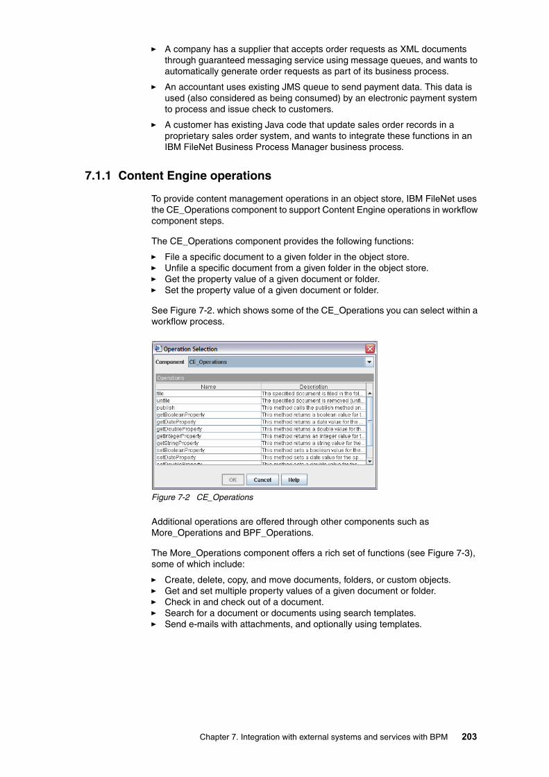
� A company has a supplier that accepts order requests as XML documents through guaranteed messaging service using message queues, and wants to automatically generate order requests as part of its business process.
� An accountant uses existing JMS queue to send payment data. This data is used (also considered as being consumed) by an electronic payment system to process and issue check to customers.
� A customer has existing Java code that update sales order records in a proprietary sales order system, and wants to integrate these functions in an IBM FileNet Business Process Manager business process.
7.1.1 Content Engine operations
To provide content management operations in an object store, IBM FileNet uses the CE_Operations component to support Content Engine operations in workflow component steps.
The CE_Operations component provides the following functions:
� File a specific document to a given folder in the object store.� Unfile a specific document from a given folder in the object store.� Get the property value of a given document or folder.� Set the property value of a given document or folder.
See Figure 7-2. which shows some of the CE_Operations you can select within a workflow process.
Figure 7-2 CE_Operations
Additional operations are offered through other components such as More_Operations and BPF_Operations.
The More_Operations component offers a rich set of functions (see Figure 7-3), some of which include:
� Create, delete, copy, and move documents, folders, or custom objects.� Get and set multiple property values of a given document or folder.� Check in and check out of a document.� Search for a document or documents using search templates.� Send e-mails with attachments, and optionally using templates.
Chapter 7. Integration with external systems and services with BPM 203

Figure 7-3 More_Operations
7.2 Web services
Web services provide universal inter-operability between heterogeneous applications using Web standards.
The Process Engine uses Web services technology to enable interaction between IBM FileNet Business Process Manager processes, as well as between IBM FileNet Business Process Manager processes and other business processes.
There are three ways that IBM FileNet Business Process Manager uses the Web services technology:
� Invoke Web services from a BPM workflow process. This enables you to use the Web services developed for other applications in your organization and the ones that are available externally on the Internet.
� Provide a BPM workflow process as a Web service and enable other applications to use this BPM workflow process to accomplish their tasks.
� Use the Web service API to write step processors (not covered in this book).
There are two message type options when invoking or creating a Web service:
� Parameters: This is an easy way to use Web services. You do not need to understand XML or XML schemas.
� XML: This is for working with complex parameters that the Parameters message type cannot handle. To use it, you need to know XML and XML schema knowledge.
Web services standardsIn order for you to understand how to use XML Web services within IBM FileNet P8, you should understand some basic definition of XML Web services.
There is a set of protocols that define how a Web service can be published, discovered, and used in a technology neutral, standard format. Among these standards are:
� Web Services Description Language (WSDL): Interface definition used to define Web services. A WSDL definition describes how to access a Web service and what operations it performs. You can use WSDL to create Web services and publish these services to UDDI.
� Universal Description, Discovery and Integration (UDDI): The directory that provides the means for discovering and publishing Web services. It is
204 Introducing IBM FileNet Business Process Manager

provided by a third party that makes these services available for inquiry. It is the equivalent of “Yellow and White Pages” of Web services.
� Extensible Markup Language (XML): The base meta-language for many Service Oriented Architecture related technologies and standards. In Web services, the messages including embedded data are written in XML format. It can be used to exchange data, so that data can go back and forth between the services provider and the client in the standard recognizable format. You can consider it as the payload (in relation to HTTP).
� Hypertext Transfer Protocol (HTTP): The vehicle that carries the XML data between systems. You can consider this as the transport.
Web services use case examplesFigure 7-4 illustrates a basic example of a Web services use case with three steps.
In the typical scenario, Company A wants to offer a service to other companies. Company A publishes the service as a Web service in a public UDDI repository (denoted as step 1). The UDDI registry entry includes the WSDL, which describes the service and how to use it.
Company B requires a particular service. Company B searches the public UDDI repository (denoted as step 2) and finds Company A's Web services offering, which meets its needs. Company B obtains the business contact information and WSDL from the UDDI registry entry, and uses (consumes) Company A's Web service (denoted as step 3).
An example of a service that Company A offers to other companies is credit score reporting (FICO Score). Company A generates revenue by offering this service to other companies through Web services. Company B, on the other hand, might be a financial institution that provide loans to customers. In order for Company B to process customer loans, company B uses (consumes) Company A’s credit score reporting Web service to help determine whether to approve or reject the loan.
Figure 7-4 Providing and using Web services by companies
7.2.1 Process orchestration
Process orchestration describes the dynamic execution of a business process from a technical view1. In the IBM FileNet Business Process Manager
UDDI Repository
Company B(Web Services consumer)
Company A(Web Services provider)
WSDL Publishes Web Services
Uses the Servic
e
1
33
2
1 Definition is extracted from http://www.serviceoriented.org/process_orchestration.html
Chapter 7. Integration with external systems and services with BPM 205

environment, it describes the ability for processes to use and provide (consume and be consumed by) Web services. An executable process can use other processes to accomplish its work. It can also provide itself as a Web service for other processes to use. Process orchestration involves combining disparate components into joined-up process flows that automates end-to-end business functions.
Process orchestration is a key BPM market requirement because it:
� Enables end-to-end processes.� Enables collaborative business process.� Enables Business to Business (B2B) transactions.� Enables Web services composition.� Complements Web services.
IBM FileNet Business Process Manager processes can use (consume) existing Web services and provide (be consumed as) Web services. The IBM FileNet Business Process Manager processes can be published as Web services, which then can be discovered through a UDDI registry.
IBM FileNet Business Process Manager offers the following Web services system functions to achieve Process orchestration:
� Invoke: Requests a service from a selected partner link.
� Receive: Provides a service in response to a Web service request.
� Reply: Sends a response to a Web service associated with a previously accepted receive system function.
Invoke functionYou can use the Invoke system function anywhere in a workflow process. The Invoke system function calls an application component that provides a Web service. This enables a workflow process to interact with and use external Web services.
Invoke is implemented as an operation on a Web services queue called WSRequest. When the IBM FileNet Business Process Manager system encounters an Invoke system function at a workflow step, the work item is routed to the WSRequest queue.
Invoke example: XYZ Corporation Authorize Credit Web servicesFigure 7-5 illustrates an example of using the Invoke system function. The workflow process shown in Figure 7-5 uses an external Web services provided by Visa.com to authorize credit card transaction.
In the workflow process, there is a workflow step called Authorize Credit Card. At this step, an Invoke system function calls a Web service from a Web services provider, Visa.com. The Web service provides a credit authorization service. Authorization request information is sent to the Web services. The Web service returns a response, either Valid or Not Valid, back to the service requester (the Authorize Credit Card workflow step) in the workflow process. The returned response is evaluated at the next step of the workflow process and then routed to the appropriate steps to accept or deny the credit card transaction.
In this example, Visa.com is the Web services provider and XYZ Corporation’s workflow process is the Web services consumer.
206 Introducing IBM FileNet Business Process Manager
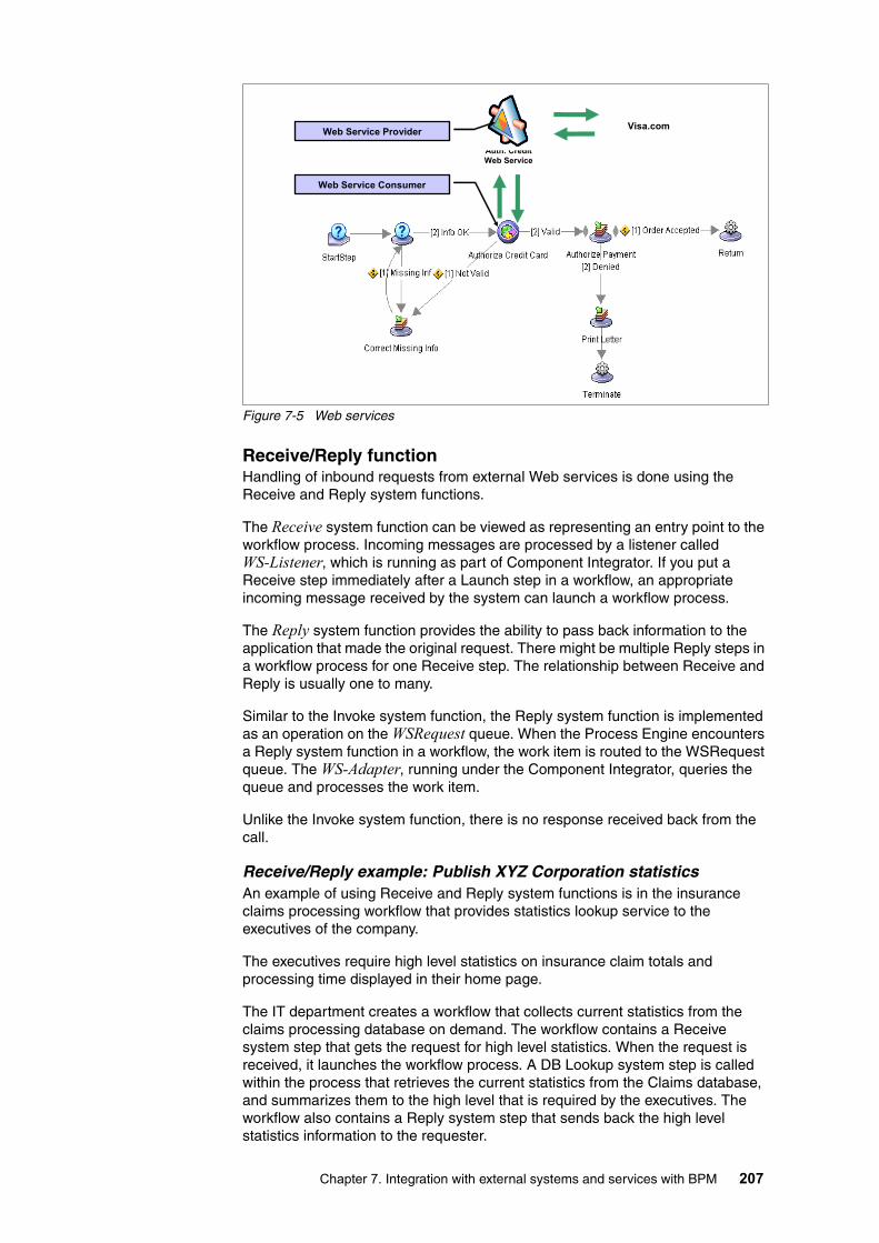
Figure 7-5 Web services
Receive/Reply functionHandling of inbound requests from external Web services is done using the Receive and Reply system functions.
The Receive system function can be viewed as representing an entry point to the workflow process. Incoming messages are processed by a listener called WS-Listener, which is running as part of Component Integrator. If you put a Receive step immediately after a Launch step in a workflow, an appropriate incoming message received by the system can launch a workflow process.
The Reply system function provides the ability to pass back information to the application that made the original request. There might be multiple Reply steps in a workflow process for one Receive step. The relationship between Receive and Reply is usually one to many.
Similar to the Invoke system function, the Reply system function is implemented as an operation on the WSRequest queue. When the Process Engine encounters a Reply system function in a workflow, the work item is routed to the WSRequest queue. The WS-Adapter, running under the Component Integrator, queries the queue and processes the work item.
Unlike the Invoke system function, there is no response received back from the call.
Receive/Reply example: Publish XYZ Corporation statistics An example of using Receive and Reply system functions is in the insurance claims processing workflow that provides statistics lookup service to the executives of the company.
The executives require high level statistics on insurance claim totals and processing time displayed in their home page.
The IT department creates a workflow that collects current statistics from the claims processing database on demand. The workflow contains a Receive system step that gets the request for high level statistics. When the request is received, it launches the workflow process. A DB Lookup system step is called within the process that retrieves the current statistics from the Claims database, and summarizes them to the high level that is required by the executives. The workflow also contains a Reply system step that sends back the high level statistics information to the requester.
Auth. Credit Web Service
Web Service Provider
Web Service Consumer
Visa.com
Chapter 7. Integration with external systems and services with BPM 207

The IT department publishes the workflow to a UDDI registry. It also modifies the executives’ home page template to include the WSDL that associated with the Web services. The executives can use the link provided in their home page to get the high level statistics they need.
Figure 7-6 illustrates the example. Notice that, in this case, the workflow process is the Web services provider, and the executive home page is the Web services consumer.
Figure 7-6 Web services Receive and Reply system functions usage example
7.3 Rules connectivity framework
The Rules Connectivity Framework (RCF) allows you to implement dynamic business rules for workflows. These rules can be simple or complex and can perform a variety of actions, such as performing if-and-then tests, setting values in data fields, or sending a work item to a submap or exception map. When you change the business rules, the changes are immediately applied to the existing workflow process.
Workflow process designer and business analysts can create and add business rules to individual steps of a workflow. Rules are used to separate business rules from the process, making it easier for a business analyst to adjust a complex process by modifying the rules rather than modifying a workflow process.
Rules can control the following types of operations in a workflow:
� Assign data to a field in the work item.� Send a work item to a workflow map.� Send a work item to a custom exception workflow map. � Skip a workflow step.� Repeat a workflow step.
To implement rules in a workflow process, the workflow designer and the business analyst work together to determine how rules should be used in the
Web Service Provider
XYZ claims Statistics DB
Web Service Consumer
Executive home page
Note: IBM FileNet Business Process Manager by itself does not provide a business rules engine. It integrates with the third-party rules engine software of your choice in its system.
208 Introducing IBM FileNet Business Process Manager

workflow, what business decisions should be controlled by the third-party rules engine, what workflow data are required for the rules engine, the appropriate names for the rule sets, and the steps in a workflow where the rules are executed. Each step in a workflow can have multiple rules, and the rules can be executed at different stages of the step, before execution, on save, or after completion.
How it worksWhen a workflow encounters a rule, the Process Engine sends a request to the Rules Listener (an interface provided by IBM FileNet), which passes the request to the rules engine. The rules engine executes the rule-set and returns the results to the Process Engine.
In IBM FileNet Business Process Manager environment, if the Rules Listener is stopped when a workflow tries to run a rule, the Process Engine sends the work item to a special queue called Instruction Sheet Interpreter (ISI). When the Rules Listener is restarted, the ISI will resubmit the work item to the Rules Listener.
If the rules engine interface is disabled in Process Configuration Console, the workflow will run and ignore any rules implemented in the workflow.
Asynchronous rules processingAlthough the rules engine can execute most rule-sets in less than a second, some rule-sets, such as database lookups, might require longer processing time. When a Process Engine process (VWKs) is waiting for a response from the rules engine, it is not available to process any other incoming requests. To improve system performance, use asynchronous rules processing (executing rules in the background). You can configure specific rule-sets to be processed this way.
Overview of implementing rulesBusiness rules are assigned to workflows using Process Designer. To implement rules in your IBM FileNet Business Process Manager system, the following steps are required:
1. Install a Rules Listener and the third-party rules software on a server.
2. Enable rules in the Process Engine (through Process Configuration Console.)
3. Configure the connection between the Process Engine and the Rules Listener (through Process Task Manager).
4. Start and stop the Rules Listener (through Process Task Manager).
It is beyond the scope of this book to cover detailed steps of setting up a rules engine and using the rules. However, in the following two chapters, we provide more details on understanding and implementing Component Integrator.
Chapter 7. Integration with external systems and services with BPM 209

210 Introducing IBM FileNet Business Process Manager

Chapter 8. Implementing Component Integrator and Web services
Previously, in Chapter 7, “Integration with external systems and services with BPM” on page 201, we introduced, from a high level business perspective, how IBM FileNet Business Process Manager integrates with external system and services.
In the current chapter, from a technical perspective, we provide information about understanding and implementing various integration options.
We cover the following topics:
� Understanding Component Integrator� Implementing Component Integrator� Understanding Web services� Implementing a process to invoke a Web service� Implementing a process as a Web service
For step-by-step instructions about how to implement Component Integrator and Web services for our case study, refer back to Chapter 6, “ÉrÉWÉlÉXÅEÉvÉçÉZÉXÇÃé¿ëï: ÉPÅ[ÉXÅEÉXÉ^ÉfÉBÅ[” on page 99.
8
© Copyright IBM Corp. 2008.All rights reserved. 211

8.1 Understanding Component Integrator
The Component Integrator is an IBM FileNet Business Process Manager service that connects a workflow with an external system. The Component Integrator provides an easy way to use external components such as Java classes in a workflow. You can use the components without programming. It is installed as part of a typical Application Engine server installation.
The Component Integrator consists of the following components:
� Component adaptors in the Application Engine server� Component queues in the Process Engine server� Component Manager in the Application Engine server
Component adaptors are used to interact with different types of components from a workflow step. You can use the Java adaptor to call Java components, and the JMS adaptor to interact with message queues. You can also write your own adaptors for different components and applications.
Component queues are created to service different types of component adaptors.
When a workflow process is executed, the Component Manager (Component Integrator Service Manager) retrieves the request from the component queues and invokes the components via the component adapters.
For each step in the workflow, the general sequence of events takes place as shown in Figure 8-1. The diagram illustrates the runtime interaction of the Component Integrator with Application Engine services (such as Component Manager), component queues in the Process Engine server, and a custom entity. The numbers in the diagram represent the steps in the operation of the Component Integrator.
Figure 8-1 shows the following flow:
� Information is sent to the component (via the adapter).
� The component performs its work and interacts with the custom entity.
� The result of the work is saved in the step (in the workflow).
� The step (in the workflow) is completed.
212 Introducing IBM FileNet Business Process Manager

Figure 8-1 Component Integrator runtime interaction example
8.1.1 Adapter and security
In Component Integrator operations, access to the installed components is controlled through Java Authentication and Authorization Service (JAAS). It allows fine-grained security control over who is running code, as opposed to where the code comes from or who signed it.
JAAS can be used for two purposes:
� Authentication: To authenticate users to reliably and securely determine who is currently executing the Java code, regardless of whether the code is running as an application, an applet, a bean, or a servlet.
� Authorization: To ensure that users have the access control rights (permissions) required to do the actions performed.
JAAS is used for the Process Engine and component authentication of users. It supports a single sign-on capability.
For information about JAAS information, see:
http://java.sun.com/products/jaas
8.2 Implementing Component Integrator
The main steps to implement Component Integrator can be summarized as follows:
1. Create and configure a component queue.
2. Import component queue operations.
3. Configure Component Manager.
4. Use components in a workflow.
Various tools and applications are used to implement Component Integrator:
Chapter 8. Implementing Component Integrator and Web services 213

� Process Configuration Console: This is used to register the components. From the tool, you import service definitions for the component. You must create a component queue for each imported class and make the component queue operations available to use during a workflow design.
� Process Designer: This is used to define component steps in a workflow. When defining a component step, you select the component, the component operation to perform at the step, and provide workflow fields as parameters for the operation.
� Process Task Manager: This is used to start, stop, and administer Component Managers. Your component must be registered with a Component Manager. This can be verified under the Required Libraries tab for the Component Manager.
� Component Manager: This polls the component queues and retrieves work items that are dispatched to them. Component Manager passes a given work item to the adaptor that is assigned to the work item's queue.
There is also a configuration option to allow the system to automatically check for new events. This option causes the Component Manager to respond to items in a component queue as they arrive. This event-driven mechanism can be enabled in addition to polling for work items.
If your IBM FileNet Business Process Manager system has been configured to automatically check for new events, the Component Manager responds to both the component's polling rate and to new events as they occur.
8.2.1 Creating and configuring a component queue
Using Process Configuration Console, you can create and configure a component queue with a Java adaptor or a JMS adaptor. Use Add Component Queue Wizard page to associate Java adaptor with a Java application, and JMS queue with a message queue.
To create a new component queue (for example, More_Operations) in the Process Configuration Console tool, follow these steps:
1. Launch the Process Configuration Console tool.
2. Connect the isolated region (right-click the isolated region and select Connect from the context menu).
Note:
To launch Process Configuration Console from Workplace XT:
1. Launch WorkplaceXT:
http://<Application Engine server name>:9080/WorkplaceXT
2. Log in.
3. Select Tools → Administration → Process Configuration Console.
To launch Process Configuration Console from Workplace:
1. Launch Workplace:
http://<Application Engine server name>:9080/Workplace
2. Log in.
3. Select Admin → Process Configuration Console.
The user you used to log into the Workplace must have administrative rights on your Process Engine server.
214 Introducing IBM FileNet Business Process Manager

3. If there is no XML file provided with the new component, right-click Component Queues and select New from the context menu. See Figure 8-2.
If an XML file is already provided, you can right-click Component Queues and select Import from XML file. Select the XML file, import it to the system. Afterwards, right-click the new component (for example, More_Operations) and select Properties. Then jump to step number 5 on page 215. The XML file might contain descriptions of the methods available in the Java class. This helps you to select the right methods to use later on in your workflow. Otherwise, you would have to either guess what they do, or manually add the descriptions for each method.
Figure 8-2 Create a new component queue
4. The Add Component Queue Wizard starts. Enter the following information and click Next:
– Queue Name: The name of the component queue. This name will appear in the list of component queues in Process Designer. For our example, we enter More_Operations.
– Description: You can optionally enter a brief description of the queue. For More_Operations, we leave it blank. See Figure 8-3.
Figure 8-3 Set component queue name and description
f. Select Java Component or JMS Component from the Adaptor drop-down list, and click Configure.
5. Configure the component:
– For Java component, set information for the following fields and click OK:
Chapter 8. Implementing Component Integrator and Web services 215

• Jar File Path: Locate and select the Jar file containing your Java component. For our More_Operations example, we select:
c:\temp\more_operations\More_Operations.jar
• Java Class: Select the appropriate class from the drop-down list of the available classes. After you select the Java class, a list of available methods display in the Available Methods box. When you configure the component queue operations, you have the opportunity to select one or more of these methods. For our More_Operations example, we select:
com/IBM FileNet/churnett/ciMore_Operations.class
Figure 8-4 shows the Jar File Path and Java Class set up for our example.
Figure 8-4 Configure Java component: Jar File Path and Java Class
– For the JMS component, set information for the following fields and click OK:
• Queue Connection Factory (use JNDI) • Queue Name (JNDI)
Java Naming and Directory Interface (JNDI) is a standard extension to the Java platform. It provides Java applications with a unified interface to multiple naming and directory services in the enterprise.
6. Set the Adaptor Properties:
– Concurrent Threads: Number of concurrent threads to execute for the component. For More_Operations, we use the default value 1.
– Polling Rate: The amount of time in milliseconds between polls of the queue by this component to look for work. For More_Operations, we use the default value 1000.
– Exception Submap: Exception handling submap used by the component. For More_Operations, we select the default, Malfunction.
– Startup Mode: Automatic or manual startup. For automatic start, the adaptor starts when the Component Manager starts. For More_Operations, we select the default, Automatic.
Important: To complete this step, the Jar file must be accessible from your local computer. At this point, you import only the class name and methods. For runtime, the Jar file must be located in the Application Engine server where the Component Manager runs. Use the Process Task Manager to specify the exact location of the Jar file and to start the component.
216 Introducing IBM FileNet Business Process Manager

7. Set the JAAS Credentials:
– User Name and Password: User name and password used for identification and permissions on both the Process Engine and potentially any external systems that will be accessed. For More_Operations, we use the administrator user ID and password.
– Configuration Context: The context you enter must be defined in the taskman.login.config file (found in …\IBM FileNet\Router). This is the JAAS login configuration file that the CE_Operations component uses by default. It contains various login context sections that components use for authentication. For More_Operations, we enter CELogin.
See Figure 8-5, which shows these selections.
Figure 8-5 Java Component set up using the Add Component Queue Wizard
8. Click Finish.
8.2.2 Importing component queue operations
After you create a new component queue, you must import operations from the selected Java class or specify JMS events.
To do so, follow these steps:
1. From the Process Configuration Console, right-click the new component queue you just created and select Properties from the context menu.
2. Select the Operations tab and click the Import icon. See Figure 8-6.
Chapter 8. Implementing Component Integrator and Web services 217

Figure 8-6 Import operations for Java component
3. Select either the Java methods or the JMS events to import, depending on the adaptor type:
– For the Java component, select one or more methods from the Available Methods drop-down list and click OK. The methods you select will be converted into operations. The method name becomes the operation name, and the method parameters become the operation parameters. In the Process Designer, you can then specify the operation and its parameters when designing the component steps of your workflow.
You can optionally rename parameters and enter descriptions for operations and parameters. These can be helpful to the workflow designer when specifying expressions for the parameters.
Important: If the imported methods depend on other Jar files, then you should make them available to the Process Configuration Console through the Register Additional Classes interface. See Figure 8-2 on page 215.
Otherwise, the Process Configuration Console will fail to load the class and thus does not display any methods.
These Jar files should also be added to the Required Libraries of Component Manager as described in 8.2.3, “Configuring Component Manager” on page 220.
218 Introducing IBM FileNet Business Process Manager

See Figure 8-7, which shows these selections.
Figure 8-7 Select methods from Java class to import for the Java component queue
– For JMS operations, enter the events for this component queue. For each event, you enter an event name, and then specify the parameters for that event. All parameters that you specify have read-only access. You can optionally enter a description for each event and for each parameter.
The events will be converted into operations. In the Process Designer, you specify the expressions for parameters in the component step of your workflow.
The JMS adaptor only supports outgoing data to a JMS queue.
4. After importing the operations, the Operations tab should look similar to Figure 8-8. Click OK.
Before you proceed, you might want to add a description for each operation so that later, when using them in a workflow design, it is easier to see which ones you should use. If you imported the component with an XML file, the description might already have been provided.
Note: You cannot import Java methods that use byte, char data types, or any Java objects other than Short, Integer, Long, Float, Double or Boolean. You can use methods that use VWAttachment and VWParticipant.
Important: Component Queue operations cannot be deleted later. After you commit the component queue definition, and it is included in a transferred workflow, you cannot delete the operations.
In addition, you must commit your changes and restart Component Manager before the new queue operations or changes take effect. Otherwise, the changes will be lost when you stop or refresh the Component Manager.
Chapter 8. Implementing Component Integrator and Web services 219

Figure 8-8 Component properties showing imported operations
5. Commit the changes by right-clicking the isolated region and selecting Commit Changes from the context menu. See Figure 8-9.
Figure 8-9 Commit changes for the component queue definition
8.2.3 Configuring Component Manager
In order to use the component queue that you created, you must configure the Component Manager to use the component queue.
The Process Task Manager in the Application Engine enables you to configure, start, and stop a Component Manager and its associated components. You can run one or more Component Managers. Each Component Manager coordinates one or more components which are responsible for delivering events from the Process Engine to an external entity such as a Web service or a messaging system. In the Process Task Manager, the Component Managers folder displays all the Component Managers currently defined. Selecting a Component Manager displays its associated components.
To configure a Component Manager to use the new component queue that you created, perform the following steps:
1. Start the Process Task Manager from the Application Engine.
2. Stop the Component Manager where you will add the component queue. You cannot update its information while it is running.
3. In the General tab, append the Queues field to include the new component queue name. Remember to add a comma in between value and the new name. There should be no space between them. For our More_Operations example, we append the queue name, More_Operations, at the end. See Figure 8-10.
220 Introducing IBM FileNet Business Process Manager

Figure 8-10 Add new component queue using Component Manager
4. In the Required LIbraries tab, specify the location of the Jar file that contains the class associated with the component queue. The Process Task Manager appends the Jar file location to the class path when starting the Component Manager. You must add a required library entry for each component queue that you create. Click Add to add the path. See Figure 8-11.
Figure 8-11 Add Jar file path (for the component queue) in the Required Libraries tab
Tip: To see what component queues are available, click Show queue names on the right side of the Queues field. It shows a list of the component queue names. Make sure you append the exact name at the end of the Queues field.
Note: The Jar file must exist on your Application Engine server.
Chapter 8. Implementing Component Integrator and Web services 221
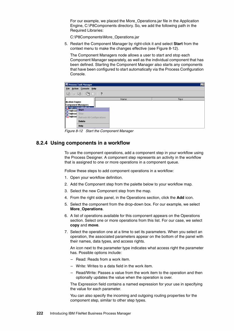
For our example, we placed the More_Operations.jar file in the Application Engine, C:\P8Components directory. So, we add the following path in the Required Libraries:
C:\P8Components\More_Operations.jar
5. Restart the Component Manager by right-click it and select Start from the context menu to make the changes effective (see Figure 8-12).
The Component Managers node allows a user to start and stop each Component Manager separately, as well as the individual component that has been defined. Starting the Component Manager also starts any components that have been configured to start automatically via the Process Configuration Console.
Figure 8-12 Start the Component Manager
8.2.4 Using components in a workflow
To use the component operations, add a component step in your workflow using the Process Designer. A component step represents an activity in the workflow that is assigned to one or more operations in a component queue.
Follow these steps to add component operations in a workflow:
1. Open your workflow definition.
2. Add the Component step from the palette below to your workflow map.
3. Select the new Component step from the map.
4. From the right side panel, in the Operations section, click the Add icon.
5. Select the component from the drop-down box. For our example, we select More_Operations.
6. A list of operations available for this component appears on the Operations section. Select one or more operations from this list. For our case, we select copy and move.
7. Select the operation one at a time to set its parameters. When you select an operation, the associated parameters appear on the bottom of the panel with their names, data types, and access rights.
An icon next to the parameter type indicates what access right the parameter has. Possible options include:
– Read: Reads from a work item.
– Write: Writes to a data field in the work item.
– Read/Write: Passes a value from the work item to the operation and then optionally updates the value when the operation is over.
The Expression field contains a named expression for your use in specifying the value for each parameter.
You can also specify the incoming and outgoing routing properties for the component step, similar to other step types.
222 Introducing IBM FileNet Business Process Manager

8.3 Understanding Web services
Web services provide universal inter-operability between heterogeneous applications using Web standards. The Process Engine uses Web services technology to enable interaction between IBM FileNet Business Process Manager processes, as well as between IBM FileNet Business Process Manager processes and other business processes and applications.
IBM FileNet Business Process Manager processes can use (consume) the existing Web services. In addition, the processes can be published as Web services, to provide services to (be consumed by) others. The published Web services can be discovered through a UDDI registry. Using Process Configuration Console, you can configure a limited UDDI registry list for an isolated region or allow users to browse for published Web services.
8.3.1 Web services adaptor
Component Integrator handles the interaction between the Process Engine and Web services (see Figure 8-13). This communication is transparent to both the workflow administrator and users. The architecture supports both polling and event driven modes for the Component Manager. You can configure the Component Manager to automatically respond to new events as they occur or poll for work.
Figure 8-13 Web services system architecture
As shown in Figure 8-13, the outbound requests for Web services are handled through WS-Adapter, running as part of the Component Integrator. The inbound requests for Web services are handled by WS-Listener, running as part of the Component Integrator. The Process Engine has a WSRequest queue and a WSPending table, which are system-managed data structures used in processing the requests for Web services.
All communications are accomplished through XML. When using Web services, you have to set data field mapping. There is no requirement for you to understand XML. The Process Designer tool automatically parses the WSDL for input and output parameters. The data fields are updated with the values of the incoming parameters at runtime.
Invoking Web servicesTo invoke a Web service in your workflow, you can create an Invoke step in the workflow. The Invoke step calls the Invoke system function, which allows you to
Note: For step-by-step instructions, we describe how to add a component step in our case study; refer to 6.5.1, “ÉRÉìÉ|Å[ÉlÉìÉgÅEÉXÉeÉbÉvÇÃê›íË” on page 132.
PE ServerPE Server ComponentComponentIntegratorIntegrator
WSWS--AdapterAdapter
WSWS--ListenerListener
Outbound
Inbound
WSPendingTable
WSRequestQueue
Chapter 8. Implementing Component Integrator and Web services 223

call any application component that has been exposed as a Web service. This enables your workflow to interact with external Web services.
The Invoke function is implemented as an operation on the WSRequest queue. When the system encounters the Invoke call, the work item is routed to the WSRequest queue. The WS-Adapter, running under the control of Component Integrator, queries the queue and processes the work item. The work item is placed in the WSPending Table waiting for coming responses from the Web service. WS-Listener listens to any inbound request.
Replying and receiving Web servicesYou can publish a process as a Web service to be used by other processes and applications. To handle inbound requests for your published Web services, use the Receive and Reply steps in your workflow.
The Receive step in a workflow calls the Receive system function. The Receive function can be viewed as representing an entry point to the workflow process. Incoming messages are processed by WS-Listener, which is running as part of Component Integrator. When processing incoming messages, the WS-Listener interacts with both the WSRequest queue and the WSPending table. If you put a Receive step immediately after a Launch Step in a workflow, an appropriate incoming message received by the system can launch a workflow process.
The Reply system function provides the ability to pass back information to the application that made the original request. There might be multiple Reply steps in a workflow process for one Receive step. The relationship between Receive and Reply is usually one to many.
The Reply step in a workflow calls the Reply system function. Similar to the Invoke function, the Reply function is implemented as an operation on the WSRequest queue. When the Process Engine encounters a Reply system function in a workflow, the work item is routed to the WSRequest queue. The WS-Adapter, running under the Component Integrator, queries the queue and processes the work item.
Unlike the Invoke function, there is no response received back from the call.
8.4 Implementing a process to invoke a Web service
The main steps to invoke a Web service can be summarized as follows:
1. Configure the UDDI registry list.
2. Define the Web service information in workflow properties.
3. Use an Invoke step in a workflow.
Note: For the step-by-step instructions that we used for our case study (excluding the configuration of the UDDI registry list), refer to 6.9, “Web ÉTÅ[ÉrÉXÇÃçÏê¨ÇýåƒÇ—èoǵ” on page 179. There, we show you how to create a workflow process as a Web service, call the Web service in a workflow process, and test the process with Web services.
224 Introducing IBM FileNet Business Process Manager

8.4.1 Configuring the UDDI registry list
Use the Process Configuration Console to configure the UDDI registry list for an isolated region. This registry list includes entries for Web services. You can search through this list to find the Web service to use or publish a workflow as a Web service in this registry.
Select or clear the check box option to allow or deny access from the Process Designer to any arbitrary WSDL. This controls access to Web services.
To configure the UDDI registry list:
1. Launch the Process Configuration Console tool.
2. Connect the isolated region (right-click the isolated region and select Connect from the context menu). See Figure 8-14.
Figure 8-14 Connect an isolated region in the Process Configuration Console
3. Right-click the isolated region and select Properties from the context menu.
4. In the Isolated Region Properties window, select the UDDI tab and then select the UDDI Registry List tab.
5. Click the Add icon to add an entry to the list. See Figure 8-15.
Figure 8-15 Add the UDDI registry list
6. Enter information for the new UDDI Registry entry:
– Name: The name that identifies this UDDI registry entry. It will be displayed in the Process Designer when using the Web services Explorer.
– Inquiry URL: The URL for inquiries to the registry. To validate a URL, select its row in the table, and click the Validate icon. This test confirms that an Inquiry URL is valid (can connect).
– Publish check box: Select this option to enable publishing services to the UDDI registry specified by the Publish URL. The Publish URL, Business
Chapter 8. Implementing Component Integrator and Web services 225

Name, Business Description, Business key, and User fields are optionally used when publishing a service.
– Enable Process Designer to enter WSDL links without browsing for Web services: Select or clear the check box option. When this option is enabled, you can type in an arbitrary WSDL URL in the workflow properties Partner Links in the Process Designer. When this option is not enabled, you are restricted to search for WSDLs in the list of UDDI registries specified for this isolated region.
7. Click OK to close the Isolated Region Properties window.
8. Commit the changes by right-clicking the isolated region and select Commit Changes from the context menu.
8.4.2 Defining Web services information in workflow properties
In the Process Designer, you must define the workflow properties for the Web services that you want to invoke.
If a workflow invokes or receives requests for Web services, specify the Web services on the Partner Links tab. If XML data fields and XML schemas are required for invoke, receive, or reply tasks, define them in the XML Data Fields tab and the XML Schemas tab. On the Web services General tab, you can specify a folder in your object store or library where any incoming attachments are stored.
To enable your workflow to invoke a Web service:
1. Start the Process Designer, open the workflow definition.
2. Open the Workflow Properties window.
3. Select the Web services tab and then select the Partner Links tab.
4. Select the Invoke check box and click the UDDI Explorer icon. See Figure 8-16.
Figure 8-16 Set Invoke WSDL URL
226 Introducing IBM FileNet Business Process Manager

5. Select UDDI registries (see Figure 8-17). Open the desired registry in the left pane. This displays any UDDI registries previously defined using the Process Configuration Console. Locate the Web service you want to invoke in the UDDI registries. The Web service can be either in public or private UDDI registries, or in workflows in the current isolated region that contain a Receive step. You can find the WSDL in the UDDI registries.
You can perform a keyword search or simply browse through the configured registry entries. To perform a keyword search, select either Business list or WSDL tModel list, then enter the first few letters of the business name or WSDL tModel name and click Execute to display the matching items. If a large number of items are returned, you can narrow the search by entering the whole name, or by using the Case sensitive and Exact match options.
Figure 8-17 Select a Web service from UDDI registries
6. Select the Web services you want to invoke.
7. Click OK to extract the WSDL information to the Partner Links table.
Chapter 8. Implementing Component Integrator and Web services 227

8.4.3 Defining an Invoke step in a workflow
To define an Invoke step in a workflow map:
1. Open the workflow definition.
2. Place an Invoke step on the workflow map using one of the following methods:
– Use a System step:
i. Add a System step to the workflow map.
ii. Select the System step icon from the workflow map.
iii. From the right panel under the Functions section, select Invoke. Use the right-arrow key to add it to the Selected Functions field. See Figure 8-18.
Figure 8-18 Use the System step with the Invoke function in workflow map
228 Introducing IBM FileNet Business Process Manager

– Use a special Invoke step:
i. Select Web services Palette from the View Palette drop-down box on the bottom of the Process Designer window.
ii. Add the Invoke step to the workflow map. See Figure 8-19.
Figure 8-19 Use Invoke System step from Web services Palette
3. Specify the general properties for the Invoke system function. If you use the System step, double-click Invoke from the Selected Functions field. If you use the special Invoke step, select the step from the map and select the General tab on the right. Enter the following information:
– Partner Link: Select the Partner Link for the Web service. The Partner Link list contains only entries already specified for Invoke Web services in the workflow properties.
– Operation: Select the appropriate operation in the Web service.
– Message Type: The Process Designer automatically selects the message type. Two message types are:
• Parameters: This uses the workflow data fields and attachments for input and output. This option is available for simple parameters.
• XML: This uses XML messages for input and output. This option is for more complex messages.
If required, you can override the Parameters selection and select XML instead, but not vice versa.
– Outgoing Parameters: If you select the Parameter message type, and the Web service that you invoke requires input, then the required fields are displayed under this field. In the Expression field, specify a previously defined data field or expression of the appropriate data type.
– Incoming Parameters: If you select the Parameter message type, and the Web service will return data, then the name and data type are displayed under this field. In the Field Name field, select a previously defined data field of the appropriate type to hold the returned data. See Figure 8-20.
Chapter 8. Implementing Component Integrator and Web services 229
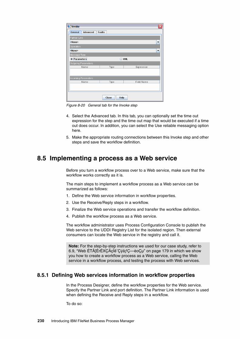
Figure 8-20 General tab for the Invoke step
4. Select the Advanced tab. In this tab, you can optionally set the time out expression for the step and the time out map that would be executed if a time out does occur. In addition, you can select the Use reliable messaging option here.
5. Make the appropriate routing connections between this Invoke step and other steps and save the workflow definition.
8.5 Implementing a process as a Web service
Before you turn a workflow process over to a Web service, make sure that the workflow works correctly as it is.
The main steps to implement a workflow process as a Web service can be summarized as follows:
1. Define the Web service information in workflow properties.
2. Use the Receive/Reply steps in a workflow.
3. Finalize the Web service operations and transfer the workflow definition.
4. Publish the workflow process as a Web service.
The workflow administrator uses Process Configuration Console to publish the Web service to the UDDI Registry List for the isolated region. Then external consumers can locate the Web service in the registry and call it.
8.5.1 Defining Web services information in workflow properties
In the Process Designer, define the workflow properties for the Web service. Specify the Partner Link and port definition. The Partner Link information is used when defining the Receive and Reply steps in a workflow.
To do so:
Note: For the step-by-step instructions we used for our case study, refer to 6.9, “Web ÉTÅ[ÉrÉXÇÃçÏê¨ÇýåƒÇ—èoǵ” on page 179 in which we show you how to create a workflow process as a Web service, calling the Web service in a workflow process, and testing the process with Web services.
230 Introducing IBM FileNet Business Process Manager

1. Start the Process Designer and open the workflow definition.
2. Open the Workflow Properties window.
3. Select the Data Fields tab and enter the data fields that will be used to hold the reply messages.
4. Select the Web services tab and then select the Partner Links tab.
5. Select the Receive/Reply check box (see Figure 8-21). Enter the following information:
– Name: Enter the name for the Web service on the left panel.– Process Port Type: Enter a name for the port.– Process Role
Figure 8-21 Workflow properties for Web services Receive/Reply
8.5.2 Using the Receive/Reply steps in a workflow
In order for a workflow process to act as a Web service, the workflow must contain at least one Receive step that accepts requests and optionally a Reply step that returns messages to the consumers. We highly recommend testing the workflow to make sure that it works before turning it over to a Web service.
To use a Receive step in a workflow:
1. In the Process Designer, start the existing workflow.
1. Open the workflow definition.
2. Place a Reply step on the workflow map using one of the following methods:
– Use a System step:
i. Add a System step to the workflow map.
ii. Select the System step icon from the workflow map.
iii. From the right panel under the Functions section, select Receive. Use the right-arrow key to add it to the Selected Functions field. See Figure 8-22.
Important: A workflow that is intended to be published as a Web service must not contain any blanks in the workflow name.
Chapter 8. Implementing Component Integrator and Web services 231

Figure 8-22 Use the System step that calls the Receive function
– Use a special Receive step:
i. Select Web services Palette from the View Palette drop-down box.
ii. Add the Receive step to the workflow map. See Figure 8-23.
Figure 8-23 Use Receive step from Web services Palette
3. Specify the general properties for the Receive function. If you use the System step, double-click Receive from the Selected Functions field. If you use the
Important: The Receive step must be the first step after the Launch step in order to launch this workflow automatically in response to an invoke of the Web service.
232 Introducing IBM FileNet Business Process Manager

special Receive step, select the step from the map and select the General tab. Enter the following information:
– Partner Link: Select the Partner Link for the Web service. The Partner Link list contains only entries already specified for Invoke Web services in the workflow properties.
– Operation: Select the appropriate operation in the Web service.
– Message Type: The Process Designer automatically selects the message type. Two message types are:
• Parameters: Uses the workflow data fields and attachments for input and output. This option is available for simple parameters.
• XML: Uses XML messages for input and output. This option is for more complex messages.
If required, you can override the Parameters selection and select XML instead, but not vice versa.
– Outgoing Parameters: Specify outgoing parameter information.
4. Select the Advanced tab. In this tab, you can optionally set the time out expression for the step and the time out map that would be executed if a time out does occur. In addition, you can select whether to authenticate user or not and restrict the users (who can invoke this Web service) to specific users or groups.
5. Make the appropriate routing connections between this Receive step and other steps.
6. Optionally, add a Reply System step if required, to reply to the Web service consumer with its information.
7. Save the workflow definition.
8.5.3 Finalizing Web services operations and transferring the workflow definition
After you finish defining your workflow as a Web service, you must finalize the Web service operations in the workflow and then transfer the workflow definition to the Process Engine. Once you transfer a finalized workflow to the Process Engine, you no longer can make changes in the input and output parameters of the Web service operations.
To finalize the Web service operations and transfer the workflow definition:
1. In the Process Designer, open the workflow properties of the workflow.
2. Select the Web services tab and then select the General tab.
3. Select the Finalize existing web services operations option. See Figure 8-24. The system prompts you with a message regarding the implications of this action.
Note: Because this workflow automatically launches when the Web service is invoked, do not assign F_Originator to any step in the workflow. Otherwise, it would not be considered a valid user.
Chapter 8. Implementing Component Integrator and Web services 233

Figure 8-24 Finalize existing Web services operations
4. Click Close.
5. Save the workflow.
6. Transfer the workflow by select File → Transfer.
The Partner Link of the finalized Web service does not identify a specific version of the workflow. Other workflow processes always invoke the latest version of the transferred workflow.
8.5.4 Publishing the workflow process as a Web service
If a workflow process is to be consumed (used) as a Web service, you must deploy the workflow process as a WSDL definition and publish it to a UDDI registry. You can publish the workflow to either your private UDDI registry or in a public UDDI registry.
Before you can publish a workflow to a UDDI registry, you must specify the appropriate UDDI registry in the isolated region properties in Configuration Console.
After creating the workflow definition and transferring it into the Process Engine, use the Process Configuration Console to publish the workflow to a UDDI registry.
To publish a workflow process as a Web service:
1. In the Process Configuration Console, select the isolated region that contains the workflow to be published. The workflow must contain the Receive system function, and it must already have been transferred to the Process Engine.
2. Right-click the isolated region and select Publish to UDDI from the context menu.
3. In the Publish to UDDI window, select the Publish Workflow tab.
4. Enter a workflow definition name in the Search Web services workflows box, or leave the field blank and search for all workflows in the current isolated region that contains a Receive system function.
5. Click the Search icon to display the list of workflow definitions. Select the workflow to publish.
6. Select a previously specified UDDI registry. The list contains only those registries from which a valid certificate can be obtained.
7. Click Publish.
Note: After you transfer the workflow definition to the Process Engine with the finalized option enabled, you cannot disable this option in the workflow definition.
234 Introducing IBM FileNet Business Process Manager

If you are publishing a business entity for the first time, enter the business name and description, and provide a user name and password for the UDDI registry. Otherwise, you cannot change the business name or user name. The information that you enter here displays in the UDDI Registry List for the isolated region.
Chapter 8. Implementing Component Integrator and Web services 235

236 Introducing IBM FileNet Business Process Manager

Chapter 9. Planning and designing a BPM solution
In this chapter we cover the process of planning and designing a content centric IBM FileNet Business Process Manager (BPM) application at a high level. This includes gathering requirements, transforming them into a workflow process, validating, and finally producing a high level architecture design.
We cover the following topics:
� Planning a BPM solution� Functional design� Detailed design
9
Note: The discussion we present here is intended for prototype application. To implement a production system, much more has to be taken into consideration. Contact your IBM FileNet lab services professional or appropriate business partners for details.
© Copyright IBM Corp. 2008.All rights reserved. 237
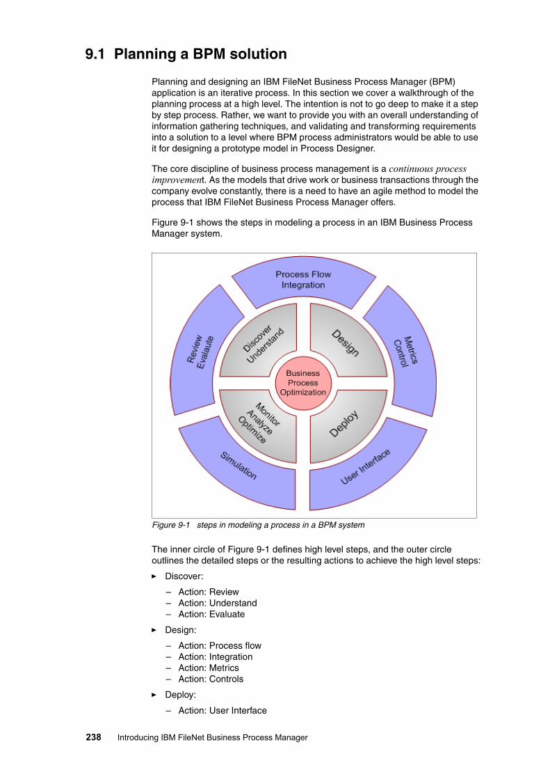
9.1 Planning a BPM solution
Planning and designing an IBM FileNet Business Process Manager (BPM) application is an iterative process. In this section we cover a walkthrough of the planning process at a high level. The intention is not to go deep to make it a step by step process. Rather, we want to provide you with an overall understanding of information gathering techniques, and validating and transforming requirements into a solution to a level where BPM process administrators would be able to use it for designing a prototype model in Process Designer.
The core discipline of business process management is a continuous process improvement. As the models that drive work or business transactions through the company evolve constantly, there is a need to have an agile method to model the process that IBM FileNet Business Process Manager offers.
Figure 9-1 shows the steps in modeling a process in an IBM Business Process Manager system.
Figure 9-1 steps in modeling a process in a BPM system
The inner circle of Figure 9-1 defines high level steps, and the outer circle outlines the detailed steps or the resulting actions to achieve the high level steps:
� Discover:
– Action: Review– Action: Understand– Action: Evaluate
� Design:
– Action: Process flow– Action: Integration– Action: Metrics– Action: Controls
� Deploy:
– Action: User Interface
238 Introducing IBM FileNet Business Process Manager

� Monitor:
– Action: Analyze– Action: Optimize– Action: Simulate
Most outer circle actions require multiple iterations. Requirements gathering, designing, building, and testing all require multiple iterations to create and fine tune a process. The analyzing and optimizing phases involve several additional iterations as business analysts and managers experiment with alternations.
There are five major areas in the outer circle to look for when designing a BPM process: process flow, integration, user interface, roles and responsibilities, and controls.
Process flowThis action entails creating process definitions and flow. In the initial iteration, focus on the core functionality that delivers the bulk of the value.
IntegrationThis action focuses on integrating with and extracting information from internal and external systems, getting the required results, and updating databases.
User interfaceAfter you understand the roles and responsibilities of all users, the next action is to ensure that the user interface windows deliver the required information and provide the right interface for users to interact with the system to perform their tasks.
Roles and responsibilityThis action focuses on exploring the management information that is deemed necessary. Helpful questions to ask include: How the data is gathered, who should have access to the data, and how the data is presented.
ControlsBusiness managers want ways to improve performance of the process, allowing them to better control process execution. They require mechanisms that help them cater to peak system performance on demand, or influence the way in which business rules apply. This action focuses on providing the controls to the business managers.
The reiterated steps in modeling a business process ensures that no surprises emerge along the way, while delivering the flexibility to change as needed.
9.1.1 Discovering and understanding the process
Every organization has a different starting point with different requirements. Some organizations already have a defined process, while others are not as well developed. Some want to emphasize automation of the process, whereas others require better traceability, visibility, and performance measurement. Either way, the first objective is to understand the process. There are at least four possibilities for a business process:
� It is a brand new process.� It is an ad-hoc workflow process.� It is currently a paper-based manual process.� It is an existing IBM FileNet Image Services (IS) eProcess.
The complexity of the discovery of a process varies based on the existing environment. You have to capture the process as it is. Assessing the existing
Chapter 9. Planning and designing a BPM solution 239

process by using a set of complementary modeling techniques allows you to understand the process better. Ideal techniques for this phase include:
� Flow diagrams or flow charts to look at the order of activities
� Role activity diagrams, also called business context diagram, to focus attention on role interactions and the desired behavior of various actors
The emphasis here is on understanding the process, not building models for transformation into code or executable process definitions. This enables both the business analyst and the business users to step outside of the business-as-usual view and see the existing process differently.
The process of gathering required information about a business problem is termed a walkthrough. Before you start this process, we recommend that you prepare yourself and your audience for it.
9.1.2 Preparing for a walkthrough
As a good practice, we recommend preparing the audience for an interview or a walkthrough.
Before starting the requirement gathering process, conduct the following preparation steps:
� Prepare a list of topics and questions.
� Prepare the participants.
� Provide information about the process and products.
� Provide questions that require advance research.
� Plan for the expected amount of time and required degree of participation.
After you and your audience are ready, look for information in the following specific areas of the business:
� Organization and business objectives.
� Industry and comparable initiatives.
� Within current processes:
– Departmental, inter-departmental, and external flows– Roles– Inefficiencies and associated costs
� Perceived gaps to desired business processes:
– Functional requirements– Non-functional requirements
� Opportunities for improvement that have not been identified, such as:
– Application integration– External process participants– Interactive process monitoring
9.1.3 Requirements gathering
In this phase, start gathering information by asking the related questions. The questioning technique differs in a great deal with the type and source of information. There are four methods of information gathering:
� Job shadowing� Interviews� Focus groups� Questionnaires
240 Introducing IBM FileNet Business Process Manager

Each of the information-gathering techniques work best in a particular scenario. Pick and choose the technique that matches the target audience and the desired results. You might use a combination of techniques. Typically, use job shadowing and interviews with heads-down knowledge workers; use focus groups with supervisors and managers; and use questionnaires with occasional or external users.
Job shadowingThe job shadowing is primarily use for observing the current business process of workers below the supervisor level and observing corporate culture.
You can use job shadowing when the as-is state is important input to the requirements. Sometimes the requirements are better observed than described. Another reason for job shadowing is that the participants might have insufficient skills to communicate their requirements or current process, or are unwilling to communicate such information completely, or are intimidated in an interview environment.
While performing job shadowing, encourage demonstration of all business scenarios. Pay attention to the processes that are time sensitive, for example, specific to a certain time of the day, week, month, or quarter. Observe the manual handling of paper or electronic files. Check out the multiple ways and user interfaces used for the existing process. Also ask for spreadsheets, e-mail, paper logs, and phone calls that are part of the process.
InterviewsUse one-on-one interviews when a few individuals have specific unique knowledge or the requirements are better described than demonstrated, for example, when job shadowing is not appropriate.
You can use an interview primarily for management and executives, and for understanding high-level business objectives and long-term vision, the big picture.
Focus groupUse focus groups when knowledge is distributed over a number of individuals. The interaction between the participants is relevant to determine the requirements. The participants are peers (or nearly so) to reduce power-based domination.
You can use a focus group primarily for supervisors and senior workers who work closely and cooperatively on a daily basis. You can also use a focus group to reach consensus on shared requirements.
Questionnaires Use questionnaires when there are many participants to survey or they are geographically remote. You can also use questionnaires for external constituents who might be inappropriate for internal meetings. Answers to specific well-defined questions, such as how many and how often, can also be surveyed in the form of questionnaires.
9.1.4 Interviews and questionnaires
When creating a list of questions, ask about how the current business processes are working and where they should be performed.
For managers and knowledge workers, it is often easiest to start with questions about the department, such as:
Chapter 9. Planning and designing a BPM solution 241

� What are the existing processes, including any process diagrams or procedures that they have created?
� How do they interface with other departments?
� How do they interface with external third parties systems, services, and customers?
� What are the existing and upcoming regulatory and customer service standards that they must meet?
As interview and questionnaires progress, you can move on to more specifics about their work, for example:
� What are the systems that they currently work with each day?
� What are the things that they find most difficult about the current processes, and what do they think can be changed to make it better?
� Are there any new reporting requirements that need to be implemented?
� What are the main software applications that they use to complete their work?
� What other applications do they make use of throughout the course of the day?
� Do they switch between applications frequently? If so, why? Do they re-key information from one system to another? If so, what is the information and why?
The end result of this process is to eventually compute a return on investment (ROI). The more information you gathered on both as-is and to-be states of the business processes, the easier it is to create a solid ROI statement. Whatever you ask, always determine the areas of current inefficiencies and the associated costs so the new or improved process can be better.
9.1.5 XYZ Corporation as-is auto claim approval process
By using the foregoing information gathering techniques, we have been able to determine the following facts about our case study of the XYZ Corporation auto claim process.
XYZ Corporation offers a range of financial and insurance products and services through a large network of field offices.
The key corporate business drivers include:
� Streamline™ business process efficiencies.� Prove and maintain adherence to government regulations.� Improve customer satisfaction.� Increase competitive advantage.
Strategic objectives for the corporation include:
� Improve business processing.� Grow business with less staff and leverage existing systems.� Reduce cycle time for claims processing.� Improve customer service.� Launch self-service customer projects.� Improve accounting.� Better risk management.� Control and manage e-mails.
From Information Technology (IT) perspectives, objectives include:
� Establishing new standards.� Reducing IT expenditure through standardization and consolidation.
242 Introducing IBM FileNet Business Process Manager

After gathering the existing process requirements and business initiatives of XYZ Corporation, we create a flowchart describing the current as-is auto claim approval process as shown in Figure 9-2.
Figure 9-2 Flowchart describing XYZ Corporation as-is auto claim approval process
After reviewing the process, we discover the following pain points associated with the current as-is auto claim process:
� It is manual and time intensive.� There is a lot of rework due to errors.� Many hours of overtime are required to correct errors.� Documents are often not signed as required.� Claimants have to wait a long time to receive checks. � The file system is manual; not only is it time consuming to use, but also
difficult to find the information in it later.
9.2 Functional design
In this section, we discuss analyzing the requirements and transforming the requirements into an IBM FileNet Business Process Manager functional design.
Call receives from policy holder
Customer Services Rep (CSR) receives
the call and takes notes
CSR creates a word document using call
notes from policy holder
CSR faxes the word document to
the head office
Mailroom Clerk receives the claim via fax
Mailroom Clerk manually date/time stamps the
claim package
Mailroom Clerk manually classifies the claim
Mailroom Clerk determines which Field Agent should work on
the claim depending on the location of accident
Mailroom Clerk sends the claim to Field Agent via internal office mail
Field Agent reviews the claim, checks for
errors and completion
Field Agent queries the policy underwriting system for claimant policy information
Field Agent prints out the relevant document
that are needed to process the claim
Field Agent determines the Adjustor who
would handle the claim based on the amount and type of the claim,
such as residential policy, $3000 or under
Adjustor reviews the claim and waits for
police report and car photos
Field Agent faxes the document to Adjustor and notifies Adjustor
about the claim
Field Agent receives and sends the police
report and photos to the head office
Mailroom Clerk receives the package, stamps it , classifies and forwards
to Adjustor
Adjustor reviews the claim package for financial controls
If the claim amount is $3000 or less,
Adjustor sends it for payment
If the claim amount is greater than $3000, Adjustor sends it to
Supervisor
Decision
Supervisor receives the package and
reviews it
Supervisor runs risk assessment using background history
Supervisor approves the claim
Decison
Supervisor rejects the claim
Supervisor writes a rejection letter
and sends it to the mailroom
Mailroom Clerk gets the letter and dispatches it
to claimant
Accounting Clerk gets the approved
claim package
Accounting Clerk sends a check to
the Claimant
Accounting Clerk sends the claim
package along with a copy of the check
to central filing
Central filing receives and stores the claim package for seven years
END
START
Chapter 9. Planning and designing a BPM solution 243

We show that using IBM FileNet Business Process Manager improves the overall process from both tangible and intangible perspectives.
9.2.1 Transforming requirements into a solution
After you have gathered detailed requirements, identify and analyze the key areas where IBM FileNet Business Process Manager can be used to provide greater benefits.
Identifying the key requirementsFirst, make sure that the business process is important for business, and that the improvement of this process is critical to long-term success of the company or organization. Next, ensure that there is an easily identifiable role for IBM FileNet Business Process Manager as part of the process improvement.
Analyzing the requirementsAnalyzing the requirements determine how a manual process can be redesigned to improve processing time. As a result, some part of the process can be automated and some part might be completely eliminated.
In our case study of auto claim process, we can eliminate the mail-room operation. This alone saves labor hours thus improving processing time and reducing the claim processing errors and overall costs.
We also look to automate certain areas for improvements. This includes identifying and assigning field agents and adjustors based upon accident location, type of a claim, and the claim amount involved.
Identifying a key business processIdentify a key business process that can be improved through IBM FileNet Business Process Manager.
Map the current as-is and future (or want) to-be business processes. Analyze the future business processes and find out more information about these business processes. This includes identifying the following information:
� The functions and roles within the process� The source of content and its method of acquisition within the process� Steps that can be automated� Integration point within the process
Overlay the IBM FileNet Business Process Manager to check for the right fit, and identify the potential gaps in functionality between the as-is and to-be business process.
The graphical view of the current requirements is presented in a flowchart in Figure 9-3 on page 245. We also create a business context diagram, Figure 9-4 on page 246, to show user roles and interaction within the system.
9.2.2 XYZ Corporation future (to-be) auto claim approval process
In 9.1.5, “XYZ Corporation as-is auto claim approval process” on page 242, we discuss XYZ Corporation’s as-is process with a flowchart. In this section, based on our analysis of the process and XYZ Corporation requirements, we transform the as-is process into a future to-be process shown in Figure 9-3.
The purpose of having a future to-be process is to ensure that we understand the process in its entirety, including the roles and responsibilities of each player in the process. This way, we can get an agreement on the process steps and on the more low level requirements.
244 Introducing IBM FileNet Business Process Manager

Figure 9-3 XYZ Corporation to-be process auto claim approval process
For auto claims, the comparison of the as-is process and the to-be process clearly shows a considerable reduction from 30 steps to 13 steps. This is done by eliminating mail-room operation and automating manual processes such as field agent and adjustor assignments.
The auto claim process depicted in Figure 9-3 on page 245 has four roles:
� Customer Service Representative (CSR)
This is an individual, customer facing role. CSRs take customers’ calls and fill out eForms with claim information such as customer name, policy number, type of incident, and location of incident. After a CSR submits an eForm, a process is automatically initiated in the IBM FileNet Business Process Manager system.
� Field agent
After the system launches a claim process, it finds the appropriate field agent and adjustor depending upon the location of accident, the type of claim, and the value of claim. The field agent then completes any missing information, including gathering supported documents such as police report and claim estimates, and routes the claim to an adjustor.
� Adjustor
The adjustor receives the claim package from the inbox, reviews the claim, checks and validates the policy document, and takes one of three actions: approve the claim, reject the claim, or escalate it to supervisor due to certain exceptions. If the adjustor approves the claim, the claim goes for payment and an approval letter is sent to the claimant. If the adjustor rejects the claim, a rejection letter is sent to the claimant. In the case of escalation, the claim
START
END
Supporting documents
preparation by Field Agent
(Human task)
Field Agent reviews the case, completes
information, determines the claim amount
(Human task)
Adjustor receives and reviews the claim
(Human task)
Final review by Adjustor
(Human task)
Claim amount?
Supervisor reviews(Human task)
Escalate for any exception
(System step)
Claim rejectionletter generated(System step)
Claim approves(System step)
Is the claim approved?
Payment processing
(Human task)
CSR interfaces with policy holder and files
the claim form (Human task) Documents
complete?
Field Agent is assigned
(System step)
Adjustor is assigned
(System step)
Claim case is created
(System step)
Approve if claim amount is less than or equal to $3000
YES
NO
YES
NO
Goes for second approval if claim amount is more than $3000
Chapter 9. Planning and designing a BPM solution 245

along with all supporting documents moves to the supervisor’s inbox for further processing.
� Supervisor
Supervisor performs thoroughly reviews the claimant folder for supporting documents, any previous claims. If required, the supervisor runs a fraud investigation and risk assessment.
After identifying the business process and the responsible roles, we create a business context diagram that explains users’ roles, connectivity, and information flow for the auto claim process. See Figure 9-4.
Figure 9-4 Business context diagram with roles and connectivity for auto claim process
Using both the to-be process and the business context diagram, you can clarify your understanding of the process and gain your customer’s commitment on the requirements.
9.2.3 Locking down the requirements
Locking down the requirements serves two purposes. The first purpose is to gain agreement from customers, including business users, IT staff, and the management. The second purpose is to have a base process to start creating a
Back OfficeMailroom Clerks
AdjustorsSupervisors
Accounting ClerksFiling Clerks
Front Office CSRs
Field Agents
1.Customer calls and submits a
claim
2. CSR takes information, and sends to head office via fax
4. Field Agent gets the claim package, reviews
it , associates police report and other related
documents, then sends it to Adjustor
6. Supervisor reviewes the claim and either
approves or rejects it. Approved claims go to Accounting Department
for payment
5. Adjustor receives the claim package, reviews it, and either approves or rejects the claim or
escalates it to Supervisor .Approved claims go to
Accounting Department for payment
7. Accounting Clerk gets the approved claim
package and writes a check and sends it to the claimant. The closed file is
then sent for filing.
3. Mailroom Clerk receives the claim via fax , timestamps the claim
package, searches for policy document, gets the name of Field Agent based on location of loss, and sends the claim package to
Field Agent via US mail
8. Filing Clerk gets the closed file and files it .
246 Introducing IBM FileNet Business Process Manager

prototype solution. The best practice is to have a formal review with all partners to achieve a common understanding and consensus.
Address the following points when locking down the requirements:
� Base requirements
� Associated costs
� Process improvement requirements
� Discussion of the solution scenario
� Discussion of the stages of implementation
� High level overview of IBM FileNet Business Process Manager products that address the requirements
� Benefit summary
9.3 Detailed design
There might be gaps between the default functions provided by the IBM FileNet Business Process Manager system as-is and the customer requirements. Identify the alternatives. If the requirements are nearly all met, and the gaps are not significant, you might need minor customization. If the gaps are significant, either a third-party solution or add-on products can be used to close the gaps.
The alternatives will become part of the detailed solution design, wherein you describe the readily available functions as-is and any of the added functions from customization.
For the purpose of our case study, we use two interfaces. The eForms interface is used by CSRs who take customers’ calls and prepare claims. The eForms helps in filling the required information interactively while the customer is on the phone. After the process is initiated, a case is created. Other users, such as field agent, adjustor, and supervisor, require a review of the case. Therefore they use a customized user interface that provides more functions, such as reviewing the claimant folder, and associating more documents with the case, such as police reports, creating comments, and approving or rejecting the claims.
9.3.1 Solution components
After you have identified the key requirements and the business process, the next step is to list the requirements and map it with IBM FileNet Business Process Manager features in order to identify any gaps.
In our case study, we map the key business requirements with the features provided by IBM FileNet Business Process Manager and other IBM FileNet P8 products. The result is shown in Table 9-1.
Table 9-1 Mapping of key business requirements with readily available P8 features
Note: For the actual implementation of the case study in Chapter 6, “ÉrÉWÉlÉXÅEÉvÉçÉZÉXÇÃé¿ëï: ÉPÅ[ÉXÅEÉXÉ^ÉfÉBÅ[” on page 99, in order to simplify the explanation, we do not show an eForms implementation. We use Workplace (XT) and the generic step processor provided with IBM FileNet Business Process Manager to complete the entire implementation.
Business requirements IBM FileNet P8 features
Replace manual steps of creating the claim, such as creating and faxing word documents, time-stamping, classifying, and reviewing for input errors for the claim.
Use eForms to fully automate this process.
Chapter 9. Planning and designing a BPM solution 247

We identified a number of manual processes that can be fully automated with readily available IBM FileNet Business Process Manager functions. We identified at least three major requirements such as case management, push method of delivering the case to users, and comprehensive audit.
As we learned earlier, the business and strategic objectives of XYZ Corporation are to gain a competitive edge, so we need to have a solution that can be deployed in a short period of time. To address this and the other key requirements such as case management, comprehensive audit, and using a push method to deliver a case to adjustor’s queue, our plan is to use IBM FileNet Business Process Framework (BPF) in conjunction with IBM FileNet Business Process Manager.
While the BPF user interface is critical to claim processors, it is “overkill” for CSR’s role. We decide to use a simple eForms-based user interface. A form can be used as a document or can be customized as an intelligent user interface. For our case study, we use the document type eForms.
Replace the manual process of locating the policy document from a manual filing system, printing, and associating the policy with the claim package and re-filing.
Through the BPF customization, a case is created automatically after the claim is submitted. The claim and all associated documents are part of the case folder.
Replace manual interaction between field agent and adjustor, which has usually delayed the claim processing.
Interaction through the IBM FileNet Business Process Manager system, with built-in Time Delay, Exception, and Escalation triggers.
Replace manual handling of associated documents that were causing delay in the processing, for example, police reports, car photos, and so on.
The Content Engine used within IBM FileNet Business Process Manager stores these documents electronically.
Improve risk assessment, which currently is completely manual, using the previous claims history.
Intelligence is built into the IBM FileNet P8 process. Based upon the risk assessment rules, the adjustor can make informed decisions.
Reduce claim approval’s overall processing time.
IBM FileNet Business Process Manager’s process has built in logic for claim approval, rejection, and escalation decisions based upon claim amount and corporate rules.
Improve payment process, which takes up time, due to not having complete information.
The claim case would have every document that is needed for a final payment.
Replace or improve the writing and dispatching of letters to the claimant, which currently are manual processes.
This is completely automated in the process step.
Provide status about the process, including who did what, which currently is hard to track down.
Comprehensive auditing in BPF Business Activity Monitor.
Properly retain and destroy claim files and associated documents, such as e-mails, according to corporate compliance policies, a feature that currently the manual process does not offer.
IBM FileNet P8 compliance framework can be proposed to address this requirement.
Business requirements IBM FileNet P8 features
248 Introducing IBM FileNet Business Process Manager

By automating the process steps in the IBM FileNet Business Process Manager system, we address a number of XYZ Corporation business objectives along with the strategic and the IT objectives such as improving customer satisfaction by reducing overall process cycle time. Automating the process also reduces labor time and errors, so more claims can now be handled correctly and speedily by the same number of people, thus reducing the overall cost per claim.
Besides automating the claim process, XYZ Corporation also ask for monitoring the claim process and using the results for further process improvements. This can be addressed by implementing Process Analyzer, Process Simulator, and Business Activity Monitor BAM.
As XYZ Corporation is looking to implement IBM FileNet Business Process Manager as an enterprise solution, they prefer to ensure that the system can scale, expand, and be able to handle future growth.
Compliance is another critical requirement that includes storing, discovering, and retaining claim files, e-mails, and other related documents for a specific period of time, and being able to disposed them according to corporate governance and regulatory requirements.
IBM FileNet Business Process Manager can use various high availability options, including server farms for scalability and expendability; while IBM FileNet Records Manager, Email Manager, and Record Crawler can be used in conjunction to address the compliance requirements.
9.3.2 Modeling the process
In this phase, we design a high level solution that shows process steps, roles, the user’s interactions with respective user interfaces, and process logic. All the design is based around IBM FileNet Business Process Manager and the additional components, in this case, eForms and BPF.
Finally we model the process in Visio using business process modeling notation, BPMN. The final BPMN design is shown in Figure 9-5. It can be imported as a BPM process design diagram into Process Designer (see Figure 9-7 on page 251).
Figure 9-5 XYZ Corporation BPM system context diagram
Auto Claim Process
Content Engine
operation
LDAP
File documents
Application Engine
Assign Field AgentAssign Adjustor
CSRCreates a case
(eForms)
Field Agentcompletes the case
information and attaches supporting documents
(BPF)
AdjustorReviews the case
(BPF)
SupervisorReviews the case
(BPF)
LDAP users’ authentication
Chapter 9. Planning and designing a BPM solution 249

9.3.3 Technical architecture overview
The system context diagram shown in Figure 9-5 provides a view of the proposed solution. For IT infrastructure, we use an architectural overview diagram so that XYZ Corporation IT staff can see both the logical and physical fit within their IT infrastructure.
Technical architecture is designed based upon the analysis of the requirements and identifying a process that shows a prototype solution. Some key reasons for creating a technical architecture are:
� To show how the solution fits within the existing IT infrastructure
� To map the solution features with the required functions
� To show connectivity to the internal and external systems
� To evaluate the delta between required and proposed specifications and its impact on the development approach
� To use it as a prototype to present solution’s functionality
Figure 9-6 shows the created technical architecture of our auto claim process. The auto claim BPM process design diagram is shown in Figure 9-7.
Figure 9-6 High level architecture for XYZ Corporation prototype auto claim process
Ethernet
Process Engine Content EngineeForms and BPFApplication Server
Web Server /Application Engine
CM OnDemand for statements
DB2 Database Server Content Manager
systemEmail Server
eForms interface used by CSR
BPF customized interface used by Field Agent, Adjustor, and
Supervisor
250 Introducing IBM FileNet Business Process Manager

Figure 9-7 Auto claim BPM process design diagram
9.3.4 Cost analysis metrics
As we discussed earlier, business process management relates to change management that results in improvements in several business areas. Some of these areas include:
� Elimination of manual labor, such as a process step that automatically sends an email transaction confirmation to a customer, which in turn replaces a manual process.
For the auto claim process, we identified the following manual processes:
– Manual filing and re-filing– Mail room handling– Calls/email
� Capturing of process information for understanding, such as the automated gathering of data showing when each item in a process is entered and exited at each processing step.
� Improvement in analysis of information and decision-making, for example, based on current data, calculate the average wait time for an item in each process step, In the current auto claim process, it would be several work hours.
� Coordination of processes across distances, making processes independent of geography, for example, a data entry process step executed by operators in home-based or remote offices, regardless of where the process initiated. In other words, CSRs and adjustors are location independent.
� Coordination between tasks and processes, such as a process step that automatically looks up client information in a line of business system based on a client account number in a CRM system that triggered the process. CSRs’ call time are greatly reduced.
� Capturing, storing, searching, and distributing of unstructured content by providing direct online access to content such as claim cases and associated documents in IBM FileNet P8 content repository.
There are two areas that directly impact ROI metrics:
App
licat
ion
Start
Age
nt
Reject Claim Generate letter Sub-process
Settle Claim Sub-process
End
End
Field Agent Review
Adj
usto
r
First Notice of Loss
Adjustor Review
Sup
ervi
sor
Police Report Witness Statement
Supervisor Review
EscalateFor exception
Approved
If <=3000 .00Approved
If > 3000.00Second approval
Creates case, validates customer policy , and
assigns adjustor
Claim Setup Sub-process
ClaimID
Reject
Claim processed
Chapter 9. Planning and designing a BPM solution 251

� Cost reduction metrics
This is typically supportable with hard data and is generally well-understood by all levels.
� Competitive advantage metrics
This requires revenue forecasting but might have a supportable model. It might be understood only at executive and management levels.
The cost reduction metrics provide tangible benefits in the following areas:
� Reduced error rates� Increased process efficiency� Reduced/consistent end-to-end service time (cost of compliance failure)� Reduced time to implement process changes� Increased process visibility (cost savings through self service)� Reduced effort to measure process� For document-driven processes, reduced manual distribution
The competitive metrics provide intangible benefits in the following areas:
� Improved time to market due to process improvement and greater agility� Reduced/consistent end-to-end service time� Increased process visibility (for example, the quality of customer service)� Increased capacity� Technology as a differentiated against competition� Increased efficiency from handling customer inquiries on-line
9.3.5 Final walkthrough
In the final walkthrough, our objective is to gain agreements on what has been done so far and proceed to the next step of creating a prototype solution, followed by a customized demonstration and a high level return on investment (ROI) for both hard and soft dollar savings.
The walkthrough discusses:
� Detailed solution design� Configuration and process design� Customizing and integration with other systems� Monitoring and reporting� Process management� Customized product demonstration; using simulation and analysis, an ROI
can be demonstrated� Return on investment on a business case
Implementing IBM FileNet Business Process Manager means introducing change management. It is important to talk about it and point to any additional savings due to changes in the process.
252 Introducing IBM FileNet Business Process Manager

Appendix A. Additional material
This book refers to additional material that can be downloaded from the Internet as described below.
Locating the Web material
The Web material associated with this book is available in softcopy on the Internet from the IBM Redbooks Web server. Point your Web browser at:
ftp://www.redbooks.ibm.com/redbooks/SG247509
Alternatively, you can go to the IBM Redbooks Web site at:
ibm.com/redbooks
Select the Additional materials and open the directory that corresponds with the IBM Redbooks form number, SG24-7509.
Using the Web material
The additional Web material that accompanies this book includes the following file:
File name DescriptionSG247509.zip Contains object store data model and workflow definition
used for the case study.
System requirements for downloading the Web material
The following system configuration is recommended:
Hard disk space: 40 MB minimumOperating System: Windows XPProcessor: Pentinum IVMemory: 512 MB
How to use the Web material
Create a subdirectory (folder) on your workstation, and unzip the contents of the Web material zip file into this folder. Follow the instruction in the README.txt file.
A
© Copyright IBM Corp. 2008.All rights reserved. 253

254 Introducing IBM FileNet Business Process Manager

Related publications
The publications listed in this section are considered particularly suitable for a more detailed discussion of the topics covered in this book.
IBM Redbooks
For information about ordering these publications, see “How to get Redbooks” on page 255. Note that some of the documents referenced here might be available in softcopy only.
� IBM FileNet Content Manager Implementation Best Practices and Recommendations, SG24-7547
Online resources
These Web sites are also relevant as further information sources:
� Product documentation for the IBM FileNet P8 Platform
http://www.ibm.com/support/docview.wss?rs=3247&uid=swg27010422
This is where you can download the IBM FileNet P8 Platform ecm_help documentation (ecm_help.zip), FileNet P8 System Overview (in PDF), and many other valuable product documentation.
How to get Redbooks
You can search for, view, or download Redbooks, Redpapers, Technotes, draft publications and Additional materials, as well as order hardcopy Redbooks, at this Web site:
ibm.com/redbooks
© Copyright IBM Corp. 2008.All rights reserved. 255

Help from IBM
IBM Support and downloads
ibm.com/support
IBM Global Services
ibm.com/services
256 Introducing IBM FileNet Business Process Manager

索引
あアイソレート・リージョン 40, 41, 63アクティブ・コンテンツ 3アプリケーション
ステップ・プロセッサー 36トラッカー 4, 36, 118, 160プロセス・アドミニストレーター 36, 160, 161, 163, 164プロセス・アナライザー 5, 11, 12, 13, 36, 37プロセス・シミュレーター 4, 5, 11, 34, 36プロセス設定コンソール 35プロセス デザイナ 100, 103, 124プロセス・デザイナー 4, 5, 7, 32, 35, 39IBM FileNet Enterprise Manager 101Process Task Manager 36
い委任 48イベント・ディスパッチャー 37イベントログ 64, 92, 106イベント・ログ 37, 41
Process Engine 12
えエスカレーション
ビジネス・プロセス 48エンジン
定義 30エンタープライズ・コンテンツ管理 (ECM) 8, 15
お応答ステップ 40オブジェクト・ストア 15, 35, 66, 69
定義 30 108
添付アイテム 108添付テンプレート 109
オペレーション・パラメーター 133, 180
か開始ステップ 6外部システム 24
き期限 48
定義 7キュー
定義 41ワークフロー・キュー 129
け警察の証明書 25, 44, 101, 135継承
ワークフロー 92ケース・スタディー 99, 101, 103, 105, 106ケース 9ケース管理モデル 9ケース・スタディー
© Copyright IBM Corp. 2008.All rights reserved.
保険金請求承認プロセス 20, 22, 23検索テンプレート 108現場調査員 2, 24, 27, 135
こコレクター・ステップ 78, 82, 47コンテンツ 3
定義 3統合された 15
コンテンツ中心のプロセス 3コンポーネント・ステップ 132, 133, 7, 58, 84
さ適化 4プロセス 2
サブマップ・ステップ 58サービス指向アーキテクチャー 39サービス指向アーキテクチャー (SOA) 39サービス・レベル・アグリーメント (SLA) 13サブスクリプション 149, 150, 157サブプロセス 7サブマップ・ステップ 6, 67, 115, 144参加者 44サンプル・ソリューション 44
しシステム関数 58, 64, 141
Reply 関数 69システム・キュー 41システム・ステップ 6, 58, 83, 141システム・プロパティー 155, 156
シンボリック名 157自動化
プロセス 2手動プロセス 2, 20, 22条件付きルーティング 47条件ルート 100, 137, 90使用状況 44
保険金請求承認プロセス 45シングル・サインオン (SSO) 35
すステップ 5
応答ステップ 40開始ステップ 6コレクター・ステップ 78, 82, 47コンポーネント・ステップ 7, 58, 84, 132, 133初のステップ 87
サブマップ・ステップ 58, 6, 67, 115, 144システム・ステップ 6, 58, 83, 141全般ステップ 6定義 6, 46Component ステップ 127General ステップ 58, 72, 126Launch ステップ 87, 127Reply ステップ 180, 190Submap ステップ 134, 126
ステップ・プロセッサー 36
257

せ請求フォルダー 132, 135, 137請求プロセス 165, 176全般ステップ 6
たターゲット・オブジェクト
クラス 146, 147, 153クラス・タイプ 146情報 167
タイマー定義 8
タスク 44タスク・マネージャー 36単一ルーティング 46単純多数 49
つツール
ステップ・プロセッサー 36トラッカー 4, 36, 118, 160プロセス・アドミニストレーター 36, 160, 161, 163, 164プロセス・アナライザー 5, 11, 12, 13, 36, 37プロセス・シミュレーター 4, 5, 11, 34, 36プロセス設定コンソール 35プロセス デザイナ 100, 103, 124プロセス・デザイナー 4, 5, 7, 32, 35, 39IBM FileNet Enterprise Manager 101Process Task Manager 36
てディレクトリー・サービス 35データ型 106データフィールド 106, 107データ型 9, 65データ層 34データフィールド 64データ・フィールド 47データベース検索 23電子フォーム 22, 25, 31電子メール通知
無効化 64添付 46, 108, 109
ワークフロー定義 66
と統合オプション
プロセス 4統合されたコンテンツ 15投票
プロセス投票 49トラッカー 4, 36, 118, 160トランザクション・プロセス 3
に入力メッセージ 33
はパートナー リンク 181, 69, 96パブリッシャー 37パラメーター 127パレット 58
BPM Palette 58, 72, 115
ひビジネス・プロセス 3, 10, 16, 20, 21, 29, 30, 43, 46, 49
エスカレーション・メカニズム 48主な要素 44初のステップ 87
定義 2Web サービス 40
ビジネス・プロセス管理 3主な焦点 2定義 2トランザクション・プロセスとコンテンツ中心のプロセス 3
ビジネス要件 106ビジネス・ルール 23, 27ビジネス・ルール・エンジン 10ビジネス・プロセス 99, 100
ふファーム
サーバー 41複数のルート 118, 119プレゼンテーション層 32プロセス
アイソレート・リージョン 63エンジンの定義 30外部システムとの統合 2期限の定義 7キュー、ワークフロー・キュー 129ケース・スタディー 20, 22, 23コンテンツ中心 3サブスクリプション 150, 157サブプロセス 7システム関数 58, 64, 83
Reply 69使用状況 45ステップ、応答ステップ 40ステップ、開始ステップ 6ステップ、コレクター・ステップ 78, 82ステップ、コンポーネント・ステップ 7, 58, 84, 132, 133ステップ、 初のステップ 87ステップ、サブマップ・ステップ 58, 67, 115, 144ステップ、システム・ステップ 58, 83, 141ステップ、全般ステップ 6ステップ定義 6, 46ステップ、Component ステップ 127ステップ、General ステップ 58, 72, 126ステップ、Launch ステップ 87, 127ステップ、Reply ステップ 180ステップ、Reply ステップ 190ステップ、Submap ステップ 126, 134ステップ、コレクター・ステップ 47タイマー定義 8タスク 44電子メール通知の無効化 64統合オプション 4トランザクション 3パレット 58, 115ビジネス・プロセス定義 2プロセス投票 49マップ定義 7マップ、ワークフロー・マップ 56, 72, 100,
258 IBM FileNet Business Process Manager の紹介

111, 144, 188マップ、Malfunction マップ 95ルーティング 46ルーティング、条件付きルーティング 47ルーティング、条件ルート 90, 100, 137ルーティング、単一ルーティング 46ルーティング、単純多数 49ルーティング、複数のルート 118, 119ルート定義 7ワークフロー・キュー 41ワークフロー定義 54, 63, 64ワークフローのプロパティー 56, 57ワークフロー・プロセス 111ワークフロー・プロセス定義 111Web サービス 198, 199XML プロセス定義言語 (XPDL) 4, 5
3プロセス デザイナ 100, 103, 124プロセス・アドミニストレーター 36プロセス・アナライザー 5, 11, 12, 13, 34, 36, 37
データベース 35OLAP 35
プロセス・インスタンス定義 42
プロセス改良サイクル 11プロセス・サーバー 41プロセス・サブスクリプション 149プロセス・シミュレーション・コンソール 36プロセス・シミュレーション・デザイナー 36プロセス・シミュレーター 4, 5, 11, 34, 36プロセス設定 32プロセス設定コンソール 35プロセス定義 5, 7, 42
定義 5プロセス デザイナ
ステップ・パレット 58ワークフローのプロパティー 56, 57Malfunction マップ 95
プロセス・デザイナー 4, 5, 7, 32, 35, 39プロセス投票 49プロセス・トラッカー 118, 160プロセスの 適化 2, 4プロセスの自動化 2プロセスの設計 4プロセスのモデル化 4プロセスのモニター 4, 5プロセス・アドミニストレーター 160, 161, 163, 164プロパティー 56, 57プロパティー・ペイン 116, 119, 126
条件の選択 183 56
へベース ワークフロー 63
ほ放棄 49保険金請求承認プロセス 20, 22, 23, 45保険契約者 20, 25, 44, 45ポートレット 8, 9
まマップ
定義 7ワークフロー・マップ 56, 72, 100, 111, 144, 188Malfunction マップ 95
みミドルウェア層 34
めメイン・ワークフロー・マップ 100, 144メッセージ 33
もモデル化
プロセス 4モニター 4
プロセス 5
ゆユーザー・インターフェース 129ユーザー・キュー 41
らリージョン
アイソレート・リージョン 40, 41, 63ルーティング 23, 46
条件付きルーティング 47単一ルーティング 46単純多数 49
ルート 5条件ルート 90, 100, 137定義 7複数のルート 118, 119並列 7
ルール・エンジン 34ルール・エンジン・フレームワーク 4ルール・フレームワーク 34ロスター 64
定義 41ロール 44
わワークフロー 100, 111, 145
バージョン 149プロセス 148
ワークフローグループ 109, 110ステップ 160名前 109
ワークフロー定義 112, 147, 161ワークフローのプロパティー 100, 105
データ・フィールド 180ワークフローグループ 161
ワークフロー名 105, 181ワークフロー・キュー 129ワークフロー・サブスクリプション 100, 145
特殊な式 151ワークフロー・プロセス 100, 103, 109, 165, 179, 180, 181, 187, 190
確認とチェック 180, 191定義 111, 171ドキュメント・タイトル 113マップ 100, 114, 124ワーク・アイテム 107Web サービス 111, 179, 190
索引 259

Web サービス・ステップ 193ワークフロー・マップ 100, 111, 188ワーク・アイテム 107, 119, 41, 42, 59, 64
データ・フィールド値 59ワーク・パケット 23, 25, 48
ルーティング 23, 25ワークフロー 2
ステップ、サブマップ・ステップ 6ステップ、システム・ステップ 6定義 2プロセス・シミュレーター 4, 5, 11, 34, 36プロセス定義 5, 7プロセス デザイナ 100, 103, 124プロセス・デザイナー 4, 5, 7, 32, 35, 39ベース ワークフロー 63ワークフロー・キュー 41
ワークフロー定義システム関数 83
ワークフロー・キュー 41ワークフローグループ 62, 66
定義 92ワークフロー・グループ 45ワークフロー定義 54, 63, 64
電子メール通知の無効化 64Reply 関数 69
ワークフローの継承 92ワークフローのプロパティー 45, 56, 57, 62ワークフロー・プロセス 94ワークフロー・プロセス定義 111ワークフロー・マップ 56, 72
メイン 100, 144ワークフロー名 63
AAdjustor Review 116, 118API
Process Engine 8, 10, 35, 36application
Process Analyzer 249Process Configuration Console 209, 214Process Designer 208, 209, 214, 215, 218, 219, 238, 249Process Simulator 249Task Manager 220
Application Engine (AE) 10, 30, 32
BBAM ダッシュボード 38BPF_Operations 203BPM Palette 115, 58, 72Business Activity Monitor 34Business Activity Monitor (BAM) 11, 13, 37, 249business process 201, 202, 223, 238, 239, 240, 241Business Process Framework (BPF) 8, 38business rule 208, 209, 239
Ccase study 242, 244CE_Operations 202, 203claim approval process 242, 244claim process 243Claim Setup サブマップ
ステップ 139, 142Component ステップ 127
component adaptor 212Component Integrator 100, 4, 7, 10, 32, 33, 36, 51, 202, 211, 212
runtime interaction 212use case examples 202
Component Manager 212, 213, 214, 216component queue 213, 214
importing operations 217required library entry 221
component queues 212, 215Component step 214, 218, 219component step
incoming and outgoing routing properties 222Content Engine (CE) 100, 101
ワークフロー・プロセス 111ワークフロー・プロセス定義 111
10, 17, 30, 36, 202コンテンツの統合 15データベース 35operations 203
Content Engine (CE) カーネル 34Content Federation Services for Image Services (CFS-IS) 15Content Manager 15
Ddata field 208, 222, 223data type 219, 222
EeForms 8, 9, 22Email Manager 17Enterprise Information System (EIS) 202
FF_Trackers 45field agent 245, 247, 248FileNet System Monitor (FSM) 17focus group 241
GGeneral ステップ 126, 58, 72
IIBM FileNet Business Process Framework (BPF) 8IBM FileNet Content Manager 15IBM FileNet Email Manager 17IBM FileNet Enterprise Manager 101IBM FileNet P8 Platform 30IBM FileNet Records Crawler 17IBM FileNet Records Manager 16IBM FileNet System Manager 17IBM FileNet System Monitor 17IBM FileNet Workplace 8, 10import
XML file 215incoming message 224Instruction Sheet Interpreter (ISI) 209interview 240, 241Invoke 206Invoke step 228invoke Web services 223isolated region 214, 220, 223, 225
limited UDDI registry list 223
260 IBM FileNet Business Process Manager の紹介

UDDI Registry List 230UDDI registry list 225, 235
JJava Authentication and Authorization Service (JAAS) 213Java class 212Java Message Service (JMS) 32Java Messaging System (JMS) 10Java Naming and Directory Interface (JNDI) 216JMS 202job shadowing 241
KKey Performance Indicator (KPI) 13, 37
LLaunch ステップ 127, 87Launch step 207, 224, 232Lotus Forms 9
Mmanual process 239, 244, 248map
workflow map 208, 222, 228message type 204, 229Microsoft Visio 4, 5modeling process 238, 249More_Operations 133, 134, 203, 214, 215
Oobject store 203, 226On-Line Analytical Processing (OLAP) 12operations
import, component queue 217
PPartner link 226, 227, 229, 230, 233, 234
Web services 226police report 245, 247process
map, workflow map 208, 222, 228modeling 238, 249step, Component step 214, 218, 219step, Invoke step 228step, Launch step 207, 224, 232step, Reply step 224, 230, 231step, System step 207, 228, 231use case 242, 244
Process Analyzer 249Process Configuration Console 209, 214process definition 239, 240Process Designer 208, 209, 214, 215, 218, 219, 238, 249
component queues 215Process Engine (PE) 100, 145, 4, 5, 10, 12, 17, 30, 35, 39, 40, 41, 202, 204, 212, 213
イベント・ログ 12コンポーネント 30, 39サーバー 41システム 34, 41データベース 35, 37, 38, 41論理的なビュー 41API 8, 10, 35, 36
server 212, 214Process Engine (PE) カーネル 34process flow 239Process Orchestration 33process orchestration 205, 206Process Simulator 249Process Task Manager 36, 220
Qquestionnaire 241queue
component queue 213, 214component queue, import operations 217Instruction Sheet Interpreter 209
queuescomponent queues 212, 215
RReceive system function 206, 207receive Web services 224Records Crawler 17Records Manager 16Redbooks Web site 255
Contact us xiregion
isolated region 214, 220, 223, 225Reply 関数 69Reply ステップ 180, 190Reply step 224, 230, 231Reply system function 206reply Web services 224Reply ステップ 180requirements gathering 239Return on investment (ROI) 242, 251Rules connectivity framework (RCF) 208rules engine 208, 209Rules Listener 209
Ssearch template 203step
Component step 214, 218, 219Invoke step 228Launch step 207, 224, 232Reply step 224, 230, 231System step 207, 228, 231
Submap ステップ 126, 134system function 223, 224, 229system functions
Invoke 206Receive 206, 207Reply 206
System Manager 17System Monitor 17System step 207, 228, 231
TTask Manager 220template
search template 203tool
Process Analyzer 249Process Configuration Console 209, 214Process Designer 208, 209, 214, 215, 218, 219, 238, 249
索引 261

Process Simulator 249Task Manager 220
UUDDI registry 205, 206UDDI registry entry 225UDDI registry list 223, 225Universal Description, Discovery and Integration (UDDI) 204, 205use case
claim approval process 242, 244user interface 238, 239, 248
WWaitForCondition 64walkthrough 240, 252Web サービス 100, 179, 180, 187, 190, 191, 194, 199Web サービス (WS) 198, 199Web サービス 4, 7, 10, 23, 27, 33, 39, 40, 51, 57, 60Web Application Toolkit (WAT) 8, 9Web services 204, 205, 211, 220, 223, 224, 229, 232, 233
inbound requests 223invoke 223outbound requests 223Partner link 226, 229, 233, 234publishing 234reply, receive 224standards 204use case examples 205workflow properties 226, 230
Web Services Description Language (WSDL) 204, 223, 225Web Site 253WebSphere Business Modeler 4, 5work item 202, 206, 214, 222, 224
data field 222workflow 202, 212, 213
Process Designer 208, 209, 214, 215, 218, 219, 238, 249Process Simulator 249
workflow definition 222, 226workflow map 208, 222, 228workflow name 231workflow process 202, 204, 212, 224, 237, 239
multiple Reply steps 207publishing as Web services 234
workflow property 224, 226Web services 229, 233Web services information 224, 226
Workplace 8, 10, 54Workplace XT 8WS-Adapter 207, 223WS-Listener 207, 223WSPending table 223WSRequest 207WSRequest queue 223
XXML スキーマ 70, 92XML プロセス定義言語 (XPDL) 4, 5XML data field 226
XML file 215, 219import 215
XML message 229, 233XML schema 204, 226XML Web services 204XYZ Corporation
サンプル・ソリューション 44
262 IBM FileNet Business Process Manager の紹介

(0.5” spine)0.475”<
->0.875”
250 <->
459 pages
Introducing IBM FileNet Business Process M
anager


®
SG24-7509-00 ISBN 0738431052
INTERNATIONAL TECHNICALSUPPORTORGANIZATION
BUILDING TECHNICALINFORMATION BASED ONPRACTICAL EXPERIENCE
IBM Redbooks are developed by the IBM International Technical Support Organization. Experts from IBM, Customers and Partners from around the world create timely technical information based on realistic scenarios. Specific recommendations are provided to help you implement IT solutions more effectively in your environment.
For more information:ibm.com/redbooks
®
Introducing IBM FileNetBusiness Process Manager
Business process design
Integration with external systems and services
Step-by-step instructions
This IBM Redbooks publication provides a basic introduction to IBM FileNet Business Process Manager (BPM) V4.0. BPM enables organizations to create, modify, and manage content centric business processes. One key advantage of BPM is its ability to work with active content, which refers to the ability of content to trigger or affect business processes.
In this book, we cover the key elements that make up a business process, including tasks, participants, roles, steps, routing, and deadlines. We describe how to use Process Designer (a BPM application) to design your business processes. In addition, we provide step-by-step instructions on how to implement a use case business process scenario.
BPM also supports integration with external systems and services through Component Integrator, Web services, and Rules Connectivity Framework. We discuss these integration options and provide instructions on how to implement the use case scenario by demonstrating some of the options.
This book is useful for system architects, process analysts, and process designers who require an understanding of IBM FileNet Business Process Manager. It also serves as a practical guide for those who want detailed instructions in order to implement a BPM system.
Back cover