Intrinsically Safe Explosion-proof System 5 Port Solenoid...
56
Intrinsically Safe Explosion-proof System 5 Port Solenoid Valve Compliant to International Standard (IEC 79) The 51-SY series (system which combines a pilot valve and SMC specific barrier (safety retain- er)) is certified to have explosion-proof performance of ExiaIIBT4, which is compliant with the “New Technical Standard” which was established based on the international standard (IEC 79). Series 51-SY5000/7000/9000 CAT.ES11-90B
-
Upload
nguyenxuyen -
Category
Documents
-
view
222 -
download
1
Transcript of Intrinsically Safe Explosion-proof System 5 Port Solenoid...

Intrinsically Safe Explosion-proof System
5 Port Solenoid Valve
Compliant to International Standard (IEC 79)The 51-SY series (system which combines a pilot valve and SMC specific barrier (safety retain-er)) is certified to have explosion-proof performance of ExiaIIBT4, which is compliant with the “New Technical Standard” which was established based on the international standard (IEC 79).
Series 51-SY5000/7000/9000CAT.ES11-90B
51-SY-B.qxd 09.3.18 11:10 AM Page 1

BA L3
L2
L2
L1
51-SY5�2051-SY7�2051-SY9�2051-SY5�4051-SY7�4051-SY9�40
Body ported
Base mounted
C[dm3/(s·bar)]
1.9
4.1
7.0
2.4
4.1
7.9
1→4/2 (P→A/B) 4/2→5/3 (A/B→EA/EB)Flow-rate characteristics
b
0.35
0.23
0.33
0.41
0.41
0.34
Cv
0.49
0.93
1.7
0.64
1.1
2.0
C[dm3/(s·bar)]
2.4
3.3
7.6
2.8
4.1
9.6
b
0.39
0.33
0.35
0.29
0.29
0.43
Cv
0.61
0.81
2.0
0.66
1.0
2.6
Series
Flow-rate Characteristics
51-SY5120-L51-SY5120-LL51-SY5120-TT51-SY7120-L51-SY7120-LL51-SY7120-TT51-SY9120-L51-SY9120-LL51-SY9120-TT
Model
DimensionL1
40
42
L3
15
18
23
L2
104
120.8
118.2
135
148.3
165.1
Dimensions
Compact, High FlowCompact, High Flow
Features 1
51-SY-B.qxd 09.3.18 11:10 AM Page 2

3 Types of Connectors� Easily maintained by adapting connector
for the lead wire (L- and LL-type)� IP65 compliant
(TT-type)
3 Types of Barriers
L-type
LL-type
L-type plug connector with cover (LL-type) Terminal type (TT-type)L-type plug connector (L-type)
Zener diode type Insulating type
Features 2
51-SY-B.qxd 09.3.18 11:10 AM Page 3

A5 1 LL 3
Intrinsically Safe Explosion-proof System5 Port Solenoid Valve
Single UnitBody Ported
How to Order
SY51 20 01
51Intrinsically safe explosion-proof structure
Explosion-proof
579
51-SY5000
51-SY7000
51-SY9000
Series
1
2-position single
Type of actuation
2
2-position double
3 Note)
3-position closed center
4 Note)
3-position exhaust center
5 Note)
3-position pressure center
Note) 3-position type is not available for the 51-SY9000 series.
Nil
FNT
Rc
G
NPT
NPTF
Thread type
∗ The 51-SY9000 has no bracket.
Nil: Without bracket F1: With foot bracket
2-position single only
F2: With side bracket
Bracket
Nil: Non-locking push type
E: Push-turn locking lever type
D: Push-turn locking slotted type
Manual override
Symbol Port size Applicable series
51-SY5000
51-SY7000
51-SY9000
1/8
1/4
1/4
3/8
Thread pipingA, B port size
01020203
Symbol Port size
ø4 one-touch fitting
ø6 one-touch fitting
ø8 one-touch fitting
ø8 one-touch fitting
ø10 one-touch fitting
ø8 one-touch fitting
ø10 one-touch fitting
ø12 one-touch fitting
Applicable series
51-SY5000
51-SY7000
51-SY9000
One-touch fitting (Metric size) Note)
C4C6C8C8C10C8C10C12
ABD
Z728.H (51-SYE100-A)
MTL728P + (51-SYE100-B)
MTL5021 (51-SYE100-D)
System Note 1) Note 2)
Note 1) Attached barrier typeThe numbers in ( ), 51-SYE100-� represents SMC’s control number.
Note 2) If the barrier is not necessary due to valve replacement etc, enter O after the system symbol.Example) 51-SY5120-AOLL3-01
Symbol
36
10152030
100
Lead wire length
300 mm
600 mm
1000 mm
1500 mm
2000 mm
3000 mm
10000 mm
Note
—
Maximum length for L-type
—
—
—
—
Semi-standard
Lead wire length
Symbol
L
Electrical entry
L-type plug connector
Electrical entry
Note) The lead wire of TT-type is connected to the terminal block.
LL
L-type plug connector with cover
TT Note)
Terminal type
Note)
If a resin tube is used, take measures against static electricity.
Warning
Series 51-SY5000/7000/9000
1
51-SY-B.qxd 09.3.18 11:10 AM Page 4

2
Body Ported Series 51-SY5000/7000/9000
Note) Based on dynamic performance test, JIS B 8375-1981.(Coil temperature: 20°C, system A, B at 24 VDC)
Specifications
Series
Fluid
Ambient and fluid temperature (°C)
Internal pilotoperating pressure range (MPa)
Max. operating frequency (Hz)
Manual override (Manual operation)
Pilot exhaust method
Lubrication
Mounting orientation
Impact/Vibration resistance (m/s2) Note)
Enclosure
Air
0.15 to 0.7
0.1 to 0.7
0.2 to 0.7
–10 to 50 (No freezing)
Non-locking push type, Push-turn locking slotted type,Push-turn locking lever type
Main/Pilot valve common exhaust
Not required
Unrestricted
150/30
IP30 (L-type), IP40 (LL-type), IP65 (TT-type)
5
3
2-position single
2-position double
3-position
2-position single, double
3-position
51-SY900051-SY5000 51-SY7000
∗ Based on IEC60529Note) Impact resistance: No malfunction occurred when it is tested in the axial direction and at the right
angles to the main valve and armature in both energized and de-energized states every once for each condition. (Values at the initial period)
Vibration resistance: No malfunction occurred in a one-sweep test between 45 and 2000 Hz. Test was performed at both energized and de-energized states in the axial direction and at the right angles to the main valve and armature. (Values at the initial period)
Solenoid Specifications
Response Time
Type of actuation51-SY500026 or less
22 or less
38 or less
51-SY700038 or less
30 or less
56 or less
51-SY900050 or less
50 or less
—
Response time (ms) (at 0.5 MPa) Note)
2-position single
2-position double
3-position
Note) Response time becomes longer by 17 ms for system D (at ON state).
Electrical entry
Coil rated voltage
Allowable voltage fluctuation
Coil insulation type
Power consumption
L-type plug connector (L),L-type plug connector with cover (LL),
Terminal type (TT)
12 VDC
–10% to +10% of rated voltage
Class B
0.52 W (at rated voltage)
Intrinsically Safe Explosion-proof System Specifications
Type of explosion-proof structure
Applicable gas or ignition temperature of steam and explosion class
Voltage to barrier
Tolerant voltage fluctuation
Intrinsically safe explosion-proof structure (ia) Note 1)
24 VDC (rated voltage of system) Note 2) Note 3)
Refer to the barrier dimensions on page 41 and 42.
Can not be used in a class-0 environment. Use in a class-2 or class-1 environ-ment.
WarningNote 1)
The valve and barrier have polarity. If voltage is supplied with wrong polarity, the barrier can not be used.
CautionNote 2)
Voltage to the valve should be 10.8 VDC (minimum value). CautionNote 3)
IIBT4
51-SY-B.qxd 09.3.18 11:10 AM Page 5

3
Series 51-SY5000/7000/9000
Flow-rate Characteristics
Series 51-SY7000
Note) [ ]: Normal position
Series 51-SY5000
Note) [ ]: Normal position
Series 51-SY9000
Valve model
Type of actuation
SingleDoubleClosed center
Exhaust center
Pressure centerSingleDoubleClosed center
Exhaust center
Pressure center
2-position
3-position
2-position
3-position
2-position
3-position
1, 5, 3(P, EA, EB)
4, 2(A, B)
1→4/2 (P→A/B) 4/2→5/3 (A/B→EA/EB)
CvbC(dm3/(s·bar)) CvbC(dm3/
(s·bar))
Port size Flow-rate characteristics Note)
51-SY5�20-�
-01
51-SY5�20-�
-C4
51-SY5�20-�
-C6
SingleDoubleClosed center
Exhaust center
Pressure center
2-position
3-position
51-SY5�20-�
-C8
1.9
1.5
0.61
0.59[0.40]
0.35
0.44
0.39
0.32[0.43]
0.49
0.41
2.4
2.5 [1.5]
1.7 0.460.43 0.350.45 1.8
2.2 [0.91] 0.460.46
[0.58] 0.380.61[0.28] 1.8
0.75
0.75
0.30
0.30[0.27]
0.43
0.36
0.64
0.64[0.53]
0.20
0.19
0.85
0.84[0.84]
1.5
1.3
0.52
0.44[0.35]
0.33
0.33
0.37
0.35[0.37]
0.33
0.33
2.0
1.8 [1.4]
0.74 0.280.40 0.570.19 0.84
0.78[0.71] 0.270.44
[0.37] 0.570.21[0.18] 0.84
1.9
1.4
0.57
0.52[0.43]
0.21
0.38
0.29
0.37[0.41]
0.45
0.39
2.3
2.0 [1.5]
1.6 0.460.29 0.380.39 1.7
2.2 [1.6] 0.500.32
[0.44] 0.410.56[0.44] 1.8
1.3 0.390.31 0.320.33 1.6
1.7 [0.80] 0.440.31
[0.47] 0.330.42[0.23] 1.7
SingleDoubleClosed center
Exhaust center
Pressure center
1/8
1/8
SingleDoubleClosed center
Exhaust center
Pressure centerSingleDoubleClosed center
Exhaust center
Pressure centerSingleDoubleClosed center
Exhaust center
Pressure center
2-position
3-position
2-position
3-position
2-position
3-position
1, 5, 3(P, EA, EB)
1 (P)port1/4
5, 3(EA, EB)
port1/8
4, 2(A, B)
1→4/2 (P→A/B) 4/2→5/3 (A/B→EA/EB)
CvbC(dm3/(s·bar)) CvbC(dm3/
(s·bar))
Port size Flow-rate characteristics Note)
51-SY7�20-�
-02
51-SY7�20-�
-C8
51-SY7�20-�
-C10
C8ø8
one-touchfitting
C8ø8
one-touchfitting
C8ø8
one-touchfitting
C10ø10one-touchfitting
C12ø12one-touchfitting
C6ø6
one-touchfitting
C4ø4
one-touchfitting
C10ø10one-touchfitting
1/4
4.1
2.5
3.2
2.4
3.8
2.5
0.81
0.82[0.54]
0.82
0.70[0.56]
0.82
0.70[0.56]
0.23
0.39
0.26
0.25
0.26
0.25
0.33
0.35[0.38]
0.37
0.42[0.46]
0.34
0.38[0.38]
0.93
0.65
0.77
0.57
0.86
0.59
3.3
3.4[2.1]
2.9 0.630.31 0.380.70 2.4
4.3[2.4] 0.580.23
[0.32] 0.390.97[0.61] 2.2
2.6 0.620.24 0.310.63 2.4
3.3[2.4] 0.600.28
[0.22] 0.340.78[0.57] 2.2
2.8 0.590.27 0.210.67 2.4
3.8[2.4] 0.610.25
[0.31] 0.380.89[0.61] 2.3
3.2
2.6[1.9]
3.2
2.7[2.0]
Valve model
Single
Double
Single
Double
Single
Double
2-position
2-position
2-position
1, 5, 3(P, EA, EB)
4, 2(A, B)
1→4/2 (P→A/B) 4/2→5/3 (A/B→EA/EB)
CvbC(dm3/(s·bar)) CvbC(dm3/
(s·bar))
Port size Flow-rate characteristics
51-SY9�20-�
-02
51-SY9�20-�
-03
51-SY9�20-�
-C8
Single
Double
2-position
51-SY9�20-�
-C10
Single
Double2-
position
51-SY9�20-�
-C12
7.0 2.00.33 0.351.7 7.6
8.0 2.00.29 0.331.9 8.0
4.3 1.70.28 0.320.96 7.1
6.1 1.90.28 0.331.4 7.9
7.0 2.20.25 0.411.6 8.6
1/4
1/4
3/8
Type of actuation
Valve model
Type of actuation
51-SY-B.qxd 09.3.18 11:10 AM Page 6

4
Body Ported Series 51-SY5000/7000/9000
Series SY2-position single
Symbol2-position single
2-position doubleSymbol
2-position double
3-position closed center/exhaust center/pressure centerSymbol3-position closed center
3-position exhaust center
3-position pressure center
(This figure shows a closed center type.)
Component Parts
Replacement Parts
Bracket Assembly Part No.
Construction
How to Change Port Block Assembly
� 51-SY5000
CautionMounting screw tightening torques
51-SY 000 (M3): 0.6 N·m51-SY9000 (M4): 1.4 N·m
57
(A)4
(B)2
(A)4
(B)2
No.
6
Description Part no.
Refer to “How to Order Port Block Assembly” on page 5.
Port block assembly
∗ The 51-SY9000 has no bracket.
∗ Refer to “How to Order Port Block Assembly” on page 5 for part number.
1(P)
3(EB)
5(EA)
1(P)
3(EB)
5(EA)
1(P)
(A)4
(B)2
3(EB)
5(EA)
If using body ported type, both A and B port sizes can be changed by replacing the port block assembly mounted on the body. When changing this block assembly, the correct screw torque must be achieved to avoid possible air leakage.
q e
qw y r
rw y
t
t
qwy r
t
Mounting screw
(Threaded type)
(Cassette type)Port block assembly
Port block assembly Fittingassembly
No.
2
3
4
5
1
Description
Resin
Resin
Resin
Aluminum, HNBR
Material
Aluminum die-casted
Note
White
White(51-SY9000: Gray)
White
—
—
Adapter plate
Body
End plate
Piston
Spool valve assembly
Description
Bracket (for F2)
Bracket (for F1)
Part no.
SX 000-16-2A (with mounting screw)57
SX 000-16-1A (with mounting screw)57
51-SY-B.qxd 09.3.18 11:10 AM Page 7
5
Series 51-SY5000/7000/9000
000SY 6A
579
51-SY5000
51-SY7000
51-SY9000
Series
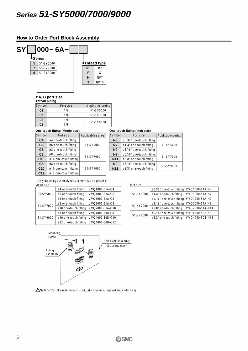
How to Order Port Block Assembly
Nil
FNT
Rc
G
NPT
NPTF
Thread type
A, B port sizeThread pipingSymbol Port size
1/8
1/4
1/4
3/8
51-SY5000
51-SY7000
51-SY9000
Applicable series
01020203
One-touch fitting (Metric size)
ø4 one-touch fitting
ø6 one-touch fitting
ø8 one-touch fitting
ø8 one-touch fitting
ø10 one-touch fitting
ø8 one-touch fitting
ø10 one-touch fitting
ø12 one-touch fitting
Symbol Port size
51-SY5000
51-SY7000
51-SY9000
Applicable series
C4C6C8C8C10C8C10C12
One-touch fitting (Inch size)Symbol Port size
51-SY5000
51-SY7000
51-SY9000
Applicable series
N3N7N9N9N11N9N11
ø5/32" one-touch fitting
ø1/4" one-touch fitting
ø5/16" one-touch fitting
ø5/16" one-touch fitting
ø3/8" one-touch fitting
ø5/16" one-touch fitting
ø3/8" one-touch fitting
Mounting screw
Fitting assembly
Port block assembly
(Cassette type)
∗ Only the fitting assembly replacement is also possible.Metric size
VVQ1000-51A-C4
VVQ1000-51A-C6
VVQ1000-51A-C8
VVQ2000-51A-C8
VVQ2000-51A-C10
VVQ4000-50B-C8
VVQ4000-50B-C10
VVQ4000-50B-C12
51-SY5000
51-SY7000
51-SY9000
ø4 one-touch fitting
ø6 one-touch fitting
ø8 one-touch fitting
ø8 one-touch fitting
ø10 one-touch fitting
ø8 one-touch fitting
ø10 one-touch fitting
ø12 one-touch fitting
Inch size
ø5/32" one-touch fitting
ø1/4" one-touch fitting
ø5/16" one-touch fitting
ø5/16" one-touch fitting
ø3/8" one-touch fitting
ø5/16" one-touch fitting
ø3/8" one-touch fitting
VVQ1000-51A-N3
VVQ1000-51A-N7
VVQ1000-51A-N9
VVQ2000-51A-N9
VVQ2000-51A-N11
VVQ4000-50B-N9
VVQ4000-50B-N11
51-SY5000
51-SY7000
51-SY9000
If a resin tube is used, take measures against static electricity.Warning
51-SY-B.qxd 09.3.18 11:11 AM Page 8

Dimensions: 51-SY5000
2-position singleL-type plug connector (L)51-SY5120-�L��-01� (-F2)
L-type plug connector with cover (LL)51-SY5120-�LL��-01� (-F2)
With foot bracket51-SY5120-�L��-01�-F1
Terminal type (TT)51-SY5120-�TT��-01� (-F2)
6
Body Ported Series 51-SY5000/7000/9000
1214
.7
L (Lead wire length) 104
Max. 10
L (Lead wire length) 120.8
ø5.
9ø
4.1
111.
8
32.5 10.5
40
14.7
47
4.538
292216.6
1.2
109.1L (Lead wire length)
(45)
ø1.
55
32.3
14.7
(1.2)
(11.7)
16.7
(40.
2)
(36.
7)
(37)
36
16.2
21
40
65
(32.3)
44 (
E-t
ype)
32.5
(20)
11.6
0.8
15
1.6
22.6
20.5
27.2
Lead wire markingNo.1 (+), No.2 (–)
0.75 mm2
Insulator: Red (+)Insulator: Black (–)
0.3 mm2
2 x ø3.2(For mounting)
Manual override
0.3 mm2
Insulator: Red (+)
Insulator: Black (–)
3 x 1/8"{P(1), EA(5), EB(3) port}
(2 x ø3.2 mounting hole)
2 x 1/8"{A(4), B(2) port}
2 x ø2.2(For manifold gasket positioning)
2 x ø3.2(manifold mounting hole)
EBPEA
AB
2 x M3 x 0.5 thread depth 3.5(For mounting bracket)
51-SY-B.qxd 09.3.18 11:11 AM Page 9

Dimensions: 51-SY5000
2-position doubleL-type plug connector (L)51-SY5220-�L��-01� (-F2)
L-type plug connector with cover (LL)51-SY5220-�LL��-01� (-F2)
Terminal type (TT)51-SY5220-�TT��-01� (-F2)
7
Series 51-SY5000/7000/9000
(88.5)
(71.7)
14.7
12
(76.8)
L (Lead wire length) 153.611
.6
16.2
36
65.4
14.7
40
(11.7)
(1.2)
37
(40.
2)
20.5 32
.5
(36.
7)
44 (
E-t
ype)
0.8
(20)15
1.6
27.2
(45)
ø1.
55
16.7
22.6
177
143.4
ø5.
9ø
4.1
0.75 mm2
Lead wire markingNo.1 (+), No.2 (–)
0.3 mm2
2 x ø3.2(manifold mounting hole)
2 x 1/8"{A(4), B(2) port}
Manual override
(2 x ø3.2 mounting hole)
3 x 1/8"{P(1), EA(5), EB(3) port}
2 x ø2.2(For manifold gasket positioning)
EBPEA
AB
Insulator: Red (+)
Insulator: Black (–)
2 x M3 x 0.5 thread depth 3.5(For mounting bracket)
0.3 mm2
Insulator: Red (+)Insulator: Black (–)
L (Lead wire length)
L (Lead wire length)
Max. 10
51-SY-B.qxd 09.3.18 11:11 AM Page 10

Dimensions: 51-SY5000
345
3-position closed center/exhaust center/pressure centerL-type plug connector (L)51-SY5 20-�L��-01� (-F2)
345
L-type plug connector with cover (LL)51-SY5 20-�LL��-01� (-F2)
345
Terminal type (TT)51-SY5 20-�TT��-01� (-F2)
8
Body Ported Series 51-SY5000/7000/9000
2 x 1/8"{A(4), B(2) port}
101.1
84.3
14.7
12
189.6
156
32.7 45.3
(89.4)
11.6
16.2
36
16.7
ø 5
.9ø
4.1
Lead wire markingNo.1 (+), No.2 (–)
2 x ø3.2(manifold mounting hole)Manual override
AB
Insulator: Red (+)
Insulator: Black (–)
0.75 mm2
0.3 mm2
Insulator: Red (+)Insulator: Black (–)
32.5
(36.
7)89.4
L (Lead wire length) 166.2
14.7
40
(11.7)
(1.2)
(37)
(40.
2)
20.5
44 (
E-t
ype)
0.8
(20)15
1.6
27.2
(45)
ø1.
55
22.6
0.3 mm2
(2 x ø3.2 mounting hole)
3 x 1/8"{P(1), EA(5), EB(3) port}
2 x ø2.2(For manifold gasket positioning)
EBPEA
2 x M3 x 0.5 thread depth 3.5(For mounting bracket)
L (Lead wire length)
L (Lead wire length)
Max. 10
51-SY-B.qxd 09.3.18 11:11 AM Page 11

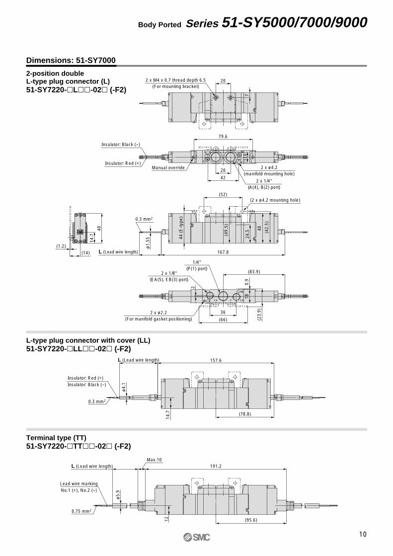
Dimensions: 51-SY7000
2-position singleL-type plug connector (L)51-SY7120-�L��-02� (-F2)
L-type plug connector with cover (LL)51-SY7120-�LL��-02� (-F2)
With foot bracket51-SY7120-�L��-02�-F1
Terminal type (TT)51-SY7120-�TT��-02� (-F2)
9
Series 51-SY5000/7000/9000
14.7
12
135
ø5.
9
L (Lead wire length)
Max. 10
L (Lead wire length) 118.2
ø4.
1
19.8
28 38
46 5.5
57
40
14.7
1.2
125
40 12.5
123.3L (Lead wire length)
42
20
(52)
14.7
(14)
1.2
40
(66)
39.4
(49.
5)
(42.
5)
40
24.5
7
29.420
(23.
9)
36
2
0.9
18
13.6
79.2
(39.4)
44 (
E-t
ype)
Lead wire markingNo.1 (+), No.2 (–)
0.75 mm2
Insulator: Red (+)Insulator: Black (–)
0.3 mm2
Manual override
Insulator: Red (+)
Insulator: Black (–)
0.3 mm2
1/4"{P(1) port}
2 x 1/8"EA(5), EB(3) port}
(2 x ø4.2 mounting hole)
2 x 1/4"{A(4), B(2) port}
2 x M4 x 0.7 thread depth 6.5(For mounting bracket)
B
A
2 x ø2.2(For manifold gasket positioning)
2 x ø4.2(manifold mounting hole)
EBPEA
51-SY-B.qxd 09.3.18 11:11 AM Page 12
Dimensions: 51-SY7000
2-position doubleL-type plug connector (L)51-SY7220-�L��-02� (-F2)
L-type plug connector with cover (LL)51-SY7220-�LL��-02� (-F2)
Terminal type (TT)51-SY7220-�TT��-02� (-F2)
10
Body Ported Series 51-SY5000/7000/9000
(78.8)
Max. 10L (Lead wire length) 191.2
(95.6)
ø5.
9ø
4.1
L (Lead wire length) 157.6
7
20
(1.2)
(14)(2
3.9)
0.9
18
(83.9)
79.6
ø1.
55
L (Lead wire length) 167.8
2
42
20
(52)
14.7
40
(66)
(49.
5)
(42.
5)
40
24.5
36
13.6
44 (
E-t
ype)
Lead wire markingNo.1 (+), No.2 (–)
0.75 mm2
Insulator: Red (+)Insulator: Black (–)
0.3 mm2
2 x M4 x 0.7 thread depth 6.5(For mounting bracket)
Insulator: Red (+)
Insulator: Black (–)
0.3 mm2
1/4"{P(1) port}
2 x 1/8"{EA(5), EB(3) port}
(2 x ø4.2 mounting hole)
2 x 1/4"{A(4), B(2) port}
B
A
2 x ø2.2(For manifold gasket positioning)
2 x ø4.2(manifold mounting hole)
Manual override
EBPEA
1214
.7
51-SY-B.qxd 09.3.18 11:11 AM Page 13
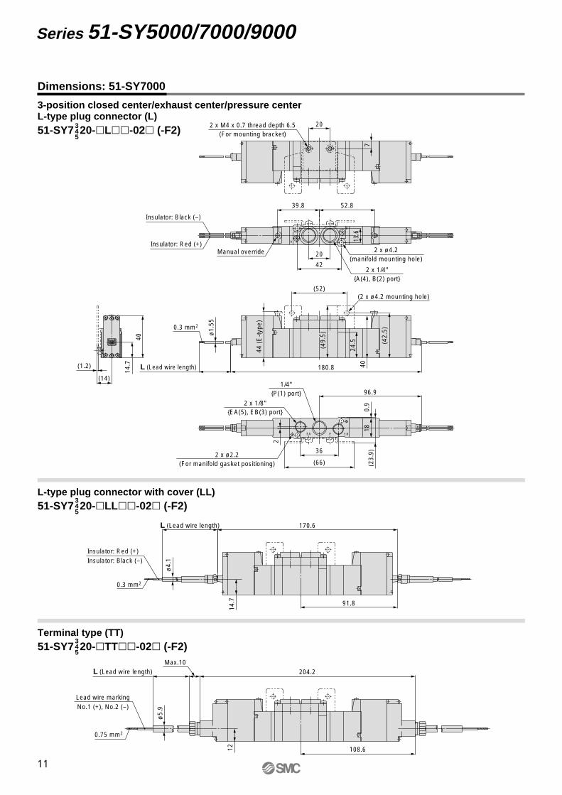
Dimensions: 51-SY7000
345
3-position closed center/exhaust center/pressure centerL-type plug connector (L)51-SY7 20-�L��-02� (-F2)
345
L-type plug connector with cover (LL)51-SY7 20-�LL��-02� (-F2)
345
Terminal type (TT)51-SY7 20-�TT��-02� (-F2)
11
Series 51-SY5000/7000/9000
52.839.8
91.8
Max. 10L (Lead wire length) 204.2
108.6
ø5.
9ø
4.1
L (Lead wire length) 170.6
7
20
(1.2)
(14)(2
3.9)
0.9
18
96.9
ø1.
55
L (Lead wire length) 180.8
2
42
20
(52)
14.7
40
(66)
(49.
5)
(42.
5)
40
24.5
36
13.6
44 (
E-t
ype)
Lead wire markingNo.1 (+), No.2 (–)
0.75 mm2
Insulator: Red (+)Insulator: Black (–)
0.3 mm2
2 x M4 x 0.7 thread depth 6.5(For mounting bracket)
Insulator: Red (+)
Insulator: Black (–)
0.3 mm2
1/4"{P(1) port}
2 x 1/8"{EA(5), EB(3) port}
(2 x ø4.2 mounting hole)
2 x 1/4"{A(4), B(2) port}
B
A
2 x ø2.2(For manifold gasket positioning)
2 x ø4.2(manifold mounting hole)
Manual override
EBPEA
1214
.7
51-SY-B.qxd 09.3.18 11:11 AM Page 14

Dimensions: 51-SY9000
0203
2-position singleL-type plug connector (L)51-SY9120-�L��- �
0203
L-type plug connector with cover (LL)51-SY9120-�LL��- �
0203
Terminal type (TT)51-SY9120-�TT��- �
12
Body Ported Series 51-SY5000/7000/9000
Max. 10
L (Lead wire length) 165.1
ø4.
1
16.7
L (Lead wire length) 148.3
36.6
153.4
ø1.
55
L (Lead wire length)
(12)
42
10
46 (
E-t
ype)
24.9 43.85
56.318
.4
109.3
6.5 (56.3)
64.2
33.6
51.5
49.8
230.
50.
5
16.7
0.75 mm2
Lead wire markingNo.1 (+), No.2 (–)
0.3 mm2
Insulator: Red (+)Insulator: Black (–)
Manual override
2 x 1/4", 3/8"{4(A), 2(B) port}
0.3 mm2
Insulator: Red (+)
Insulator: Black (–)
2 x ø4.4(Mounting hole)
3 x 1/4"{1(P), 3(EB), 5(EA) port}
B2A4
EB3P1EA5
3 x ø3.2(manifold mounting hole)
14
51-SY-B.qxd 09.3.18 11:11 AM Page 15
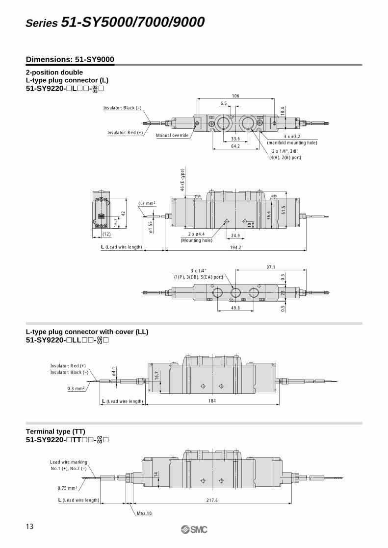
Dimensions: 51-SY9000
0203
2-position doubleL-type plug connector (L)51-SY9220-�L��- �
0203
L-type plug connector with cover (LL)51-SY9220-�LL��- �
0203
Terminal type (TT)51-SY9220-�TT��- �
13
Series 51-SY5000/7000/9000
217.6
184
106
194.2
97.1
Max. 10
L (Lead wire length)
ø4.
1
16.7
L (Lead wire length)
36.6
ø1.
55
L (Lead wire length)
(12)
42
10
46 (
E-t
ype)
24.9
18.4
6.5
64.2
33.6
51.5
49.8
230.
50.
5
16.7
0.75 mm2
Lead wire markingNo.1 (+), No.2 (–)
0.3 mm2
Insulator: Red (+)Insulator: Black (–)
Manual override
2 x 1/4", 3/8"{4(A), 2(B) port}
0.3 mm2
Insulator: Red (+)
Insulator: Black (–)
2 x ø4.4(Mounting hole)
3 x 1/4"{1(P), 3(EB), 5(EA) port}
B2A4
EB3P1EA5
3 x ø3.2(manifold mounting hole)
14
51-SY-B.qxd 09.3.18 11:11 AM Page 16
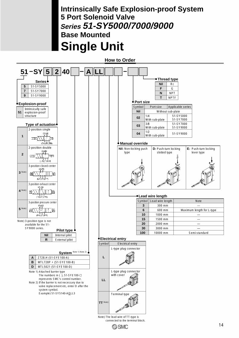
Intrinsically Safe Explosion-proof System5 Port Solenoid Valve
Single UnitBase Mounted
A5 2 LLSY51 40
Explosion-proof
579
51-SY5000
51-SY7000
51-SY9000
Series
1
2-position single
Type of actuation
2
2-position double
3 Note)
3-position closed center
4 Note)
3-position exhaust center
5 Note)
3-position pressure center
Note) 3-position type is not available for the 51-SY9000 series.
Nil
FNT
Rc
G
NPT
NPTF
Thread type
Symbol
L
Electrical entry
L-type plug connector
Electrical entry
Note) The lead wire of TT-type is connected to the terminal block.
LL
L-type plug connector with cover
TT Note)
Terminal type
ABD
Z728.H (51-SYE100-A)
MTL728P + (51-SYE100-B)
MTL5021 (51-SYE100-D)
System Note 1) Note 2)
Symbol
3 6 10 15 20 30100
Lead wire length
300 mm
600 mm
1000 mm
1500 mm
2000 mm
3000 mm
10000 mm
Note
—
Maximum length for L-type
—
—
—
—
Semi-standard
Lead wire length
Symbol
Nil
Port size
Without sub-plate
3/8With sub-plate
02 51-SY500051-SY7000
51-SY700051-SY9000
03
1/2With sub-plate
04 51-SY9000
Applicable series
1/4With sub-plate
Port size
Nil: Non-locking push type
E: Push-turn locking lever type
D: Push-turn locking slotted type
Manual override
Nil
RInternal pilot
External pilot
Pilot type
Series 51-SY5000/7000/9000
How to Order
51Intrinsically safe explosion-proof structure
Note 1) Attached barrier typeThe numbers in ( ), 51-SYE100-� represents SMC’s control number.
Note 2) If the barrier is not necessary due to valve replacement etc, enter O after the system symbol.Example) 51-SY5140-AOLL3
14
51-SY-B.qxd 09.3.18 11:11 AM Page 17

15
Series 51-SY5000/7000/9000
Specifications
Series
Fluid
Internal pilotoperating pressure range (MPa)
External pilotoperating pressure range (MPa)
Ambient and fluid temperature (°C)
Max. operating frequency (Hz)
Manual override (Manual operation)
Pilot exhaust method
51-SY5000 51-SY7000Air
0.15 to 0.7
0.1 to 0.7
0.2 to 0.7
–100 kPa to 0.7
0.25 to 0.7
0.25 to 0.7
0.25 to 0.7
–10 to 50 (No freezing)
Main/Pilot valve common exhaust
Pilot valve individual exhaust
Not required
Unrestricted
150/30
IP30 (L-type), IP40 (LL-type), IP65 (TT-type)
Lubrication
Mounting orientation
Impact/Vibration resistance (m/s2) Note)
Enclosure
5
3
51-SY9000
2-position single
2-position double
3-position
Operating pressure range
Pilotpressure range
2-position single, double
3-position
Internal pilot
External pilot
Non-locking push type, Push-turn locking slotted type,Push-turn locking lever type
2-position single
2-position double
3-position
∗ Based on IEC60529Note) Impact resistance: No malfunction occurred when it is tested in the axial direction and at the right
angles to the main valve and armature in both energized and de-energized states every once for each condition. (Values at the initial period)
Vibration resistance: No malfunction occurred in a one-sweep test between 45 and 2000 Hz. Test was performed at both energized and de-energized states in the axial direction and at the right angles to the main valve and armature. (Values at the initial period)
Note) Based on dynamic performance test, JIS B 8375-1981.(Coil temperature: 20°C, system A, B at 24 VDC)
Solenoid Specifications
Response Time
Type of actuation51-SY500026 or less
22 or less
38 or less
51-SY700038 or less
30 or less
56 or less
51-SY900050 or less
50 or less
—
Response time (ms) (at 0.5 MPa) Note)
2-position single
2-position double
3-position
Note) Response time becomes longer by 17 ms for system D (at ON state).
Electrical entry
Coil rated voltage
Allowable voltage fluctuation
Coil insulation type
Power consumption
L-type plug connector (L),L-type plug connector with cover (LL),
Terminal type (TT)
12 VDC
–10% to +10% of rated voltage
Class B
0.52 W (at rated voltage)
Intrinsically Safe Explosion-proof System Specifications
Type of explosion-proof structure
Applicable gas or ignition temperature of steam and explosion class
Voltage to barrier
Tolerant voltage fluctuation
Intrinsically safe explosion-proof structure (ia) Note 1)
24 VDC (rated voltage of system) Note 2) Note 3)
Refer to the barrier dimensions on page 41 and 42.
Can not be used in a class-0 environment. Use in a class-2 or class-1 environ-ment.
WarningNote 1)
The valve and barrier have polarity. If voltage is supplied with wrong polarity, the barrier can not be used.
CautionNote 2)
Voltage to the valve should be 10.8 VDC (minimum value). CautionNote 3)
IIBT4
51-SY-B.qxd 09.3.18 11:11 AM Page 18

16
Base Mounted Series 51-SY5000/7000/9000
Series 51-SY5000
Flow-rate Characteristics
Note) [ ]: Normal position
Series 51-SY7000
Note) [ ]: Normal position
Series 51-SY9000
Valve model Type of actuation 1→4/2 (P→A/B) 4/2→5/3 (A/B→EA/EB)Port sizeFlow-rate characteristics Note)
51-SY7�40-�-02
Single
Double
Closed center
Exhaust center
Pressure center
2-position
3-position
C(dm3/(s·bar)) Cvb bC(dm3/(s·bar)) Cv
1/4
51-SY7�40-�-03
Single
Double
Closed center
Exhaust center
Pressure center
2-position
3-position
3/8
4.1
3.0
1.0
0.72
0.41
0.43
0.29
0.41
1.1
0.80
4.1
2.6
2.61.1
[0.49]0.42
0.35[0.48]
0.714.7[1.7]
5.3[2.3]
0.630.39[0.49]
0.491.3 [0.65]
2.2
4.9
3.0
1.1
0.73
0.29
0.40
0.27
0.45
1.2
0.80
4.5
2.6
2.61.1
[0.49]0.42
0.35[0.48]
0.714.8[1.7]
5.3[2.3]
0.660.31[0.51]
0.451.3 [0.64]
2.3
Valve model Type of actuation 1→4/2 (P→A/B) 4/2→5/3 (A/B→EA/EB)Port sizeFlow-rate characteristics
51-SY9�40-�-03
Single
Double2-
position
C(dm3/(s·bar)) Cvb bC(dm3/(s·bar)) Cv
3/8
51-SY9�40-�-04
Single
Double2-
position 1/2
7.9 2.60.34 0.432.0 9.6
8.0 2.50.48 0.292.2 10
Valve model Type of actuation 1→4/2 (P→A/B) 4/2→5/3 (A/B→EA/EB)Port size
Flow-rate characteristics Note)
51-SY5�40-�-02
Single
Double
Closed center
Exhaust center
Pressure center
2-position
3-position
C(dm3/(s·bar)) Cvb bC(dm3/(s·bar)) Cv
1/4
2.4
1.8
0.66
0.47
0.41
0.47
0.29
0.40
0.64
0.50
2.8
1.8
1.40.72
[0.37]0.55
0.33[0.48]
0.443.0[1.2]
3.3[0.84]
0.480.36[0.60]
0.400.85[0.28]
1.8
51-SY-B.qxd 09.3.18 11:11 AM Page 19

17
Construction
Series 51-SY5000/7000/9000
Series SY
2-position singleSymbol
2-position single
2-position doubleSymbol
2-position double
3-position closed center/exhaust center/pressure centerSymbol
3-position closed center
3-position exhaust center
3-position pressure center
(This figure shows a closed center type.)
Component Parts
qt
uy
rw e
qt
u y
rw
qt
u y
rw
CautionMounting screw tightening torques
M3: 0.8 N·mM4: 1.4 N·m
No.
2
345
1Description
Resin
ResinResin
Aluminum, HNBR
MaterialAluminum die-casted
NoteWhiteWhite
(51-SY9000: Gray)White
——
Adapter plate
Body
End platePistonSpool valve assembly
Replacement Parts
∗ Thread type
No.
6
7
—
Description
Sub-plate
GasketRound head combination screw
Note
Aluminum die-casted
HNBRFor valve mounting(Flat nickel plated)
Part no. 51-SY5�40 51-SY7�40 51-SY9�40
1(P)
4(A)
2(B)
3(EB)
5(EA)
1(P)
4(A)
2(B)
3(EB)
5(EA)
1(P)
4(A)
2(B)
3(EB)
5(EA)
SY7000-11-11
M4 x 31
1/4: SY7000-27-13/8: SY7000-27-2
∗∗
SY5000-11-15
M3 x 26
SY5000-27-1 ∗
SY9000-11-2SY9000-18-2
(M3 x 42)
3/8: SY9000-27-11/2: SY9000-27-2
∗∗
51-SY-B.qxd 09.3.18 11:11 AM Page 20

Dimensions: 51-SY5000
2-position singleL-type plug connector (L)51-SY5140(R)-�L��-02�
L-type plug connector with cover (LL)51-SY5140(R)-�LL��-02�
Terminal type (TT)51-SY5140(R)-�TT��-02�
18
Base Mounted Series 51-SY5000/7000/9000
34.5
37.2
Max. 10L (Lead wire length) 120.8
ø5.
9
L (Lead wire length) 104
ø4.
1
17.5
65
109.1
4.356
35
4
60.3
8.34837.2
L (Lead wire length)
66.5
(E-t
ype)
62.5
17
ø1.
55
17
15.5 15.5
19
22
9.5
28
18 18
9.5
18
Lead wire markingNo.1 (+), No.2 (–)
0.75 mm2
Insulator: Red (+)Insulator: Black (–)
0.3 mm2
0.3 mm2
Insulator: Red (+)
Insulator: Black (–)
Manual override
A B
M5 x 0.8(Pilot EXH port)
<For external pilot type>
PE X
M5 x 0.8(External pilot port)
P EBEA
BA
5 x 1/4"(Piping port)
2 x ø4.3(For mounting)
51-SY-B.qxd 09.3.18 11:11 AM Page 21

Dimensions: 51-SY5000
2-position doubleL-type plug connector (L)51-SY5240(R)-�L��-02�
L-type plug connector with cover (LL)51-SY5240(R)-�LL��-02�
Terminal type (TT)51-SY5240(R)-�TT��-02�
19
Series 51-SY5000/7000/9000
153.6
L (Lead wire length)
ø1.
55
34.5
37.2
(71.7)
(88.5)
143.4
Max. 10
177L (Lead wire length)
ø5.
9
L (Lead wire length)
ø4.
1
62.5
4
17.5
65.4
17.5
56 35
4
48
37.2
66.5
(E-t
ype)
1717
15.5 15.5
19
22
9.5
28
18 18
9.5
18
Insulator: Red (+)
Insulator: Black (–)
0.3 mm2
Lead wire markingNo.1 (+), No.2 (–)
0.75 mm2
Insulator: Red (+)Insulator: Black (–)
0.3 mm2
Manual override
A
B
M5 x 0.8(Pilot EXH port)
<For external pilot type>
PE X
M5 x 0.8(External pilot port)
P EBEA
BA
5 x 1/4"(Piping port)
2 x ø4.3(For mounting)
51-SY-B.qxd 09.3.18 11:11 AM Page 22

Dimensions: 51-SY5000
345
L-type plug connector with cover (LL)51-SY5 40(R)-�LL��-02�
345
Terminal type (TT)51-SY5 40(R)-�TT��-02�
345
3-position closed center/exhaust center/pressure centerL-type plug connector (L)51-SY5 40(R)-�L��-02�
20
Base Mounted Series 51-SY5000/7000/9000
101.1
84.3
89.4
44.1
166.2
L (Lead wire length)
ø1.
55
34.5
37.2
156
Max. 10
189.6L (Lead wire length)
ø5.
9
L (Lead wire length)
ø4.
1
62.5
4
17.5
78
17.5
56
35
4
48
37.2
66.5
(E-t
ype)
1717
15.5 15.5
19
22
9.5
28
18 18
9.5
18
Insulator: Red (+)
Insulator: Black (–)
0.3 mm2
Lead wire markingNo.1 (+), No.2 (–)
0.75 mm2
Insulator: Red (+)Insulator: Black (–)
0.3 mm2
Manual override
A
BM5 x 0.8
(Pilot EXH port)<For external pilot type>
PE X
M5 x 0.8(External pilot port)
P EBEA
BA
5 x 1/4" (Piping port)
2 x ø4.3(For mounting)
51-SY-B.qxd 09.3.18 11:11 AM Page 23

Dimensions: 51-SY7000
2-position singleL-type plug connector (L)51-SY7140(R)-�L��- �
L-type plug connector with cover (LL)51-SY7140(R)-�LL��- �
Terminal type (TT)51-SY7140(R)-�TT��- �
21
Series 51-SY5000/7000/9000
0203
0203
0203 Max. 10
L (Lead wire length) 135
39ø5.
9
L (Lead wire length) 118.2
41.7ø
4.1
ø1.
55
4
23
71.2
(E
-typ
e)
67.2
L (Lead wire length)
21.5
41.7
123.3
6.4
10.4
79.2
69
22.5
38 46
21
21
21.5
13.521
61
26.5
13.5
11.5
33
20.5 20.5
Lead wire markingNo.1 (+), No.2 (–)
0.75 mm2
Insulator: Red (+)Insulator: Black (–)
0.3 mm2
Insulator: Red (+)
Insulator: Black (–)
0.3 mm2
Manual override
B
A
P
BA
EBEA
PE
X
M5 x 0.8(Pilot EXH port)
<For external pilot type>
M5 x 0.8(External pilot port)
5 x 3/8", 1/4"(Piping port)
2 x ø4.3(For mounting)
51-SY-B.qxd 09.3.18 11:11 AM Page 24
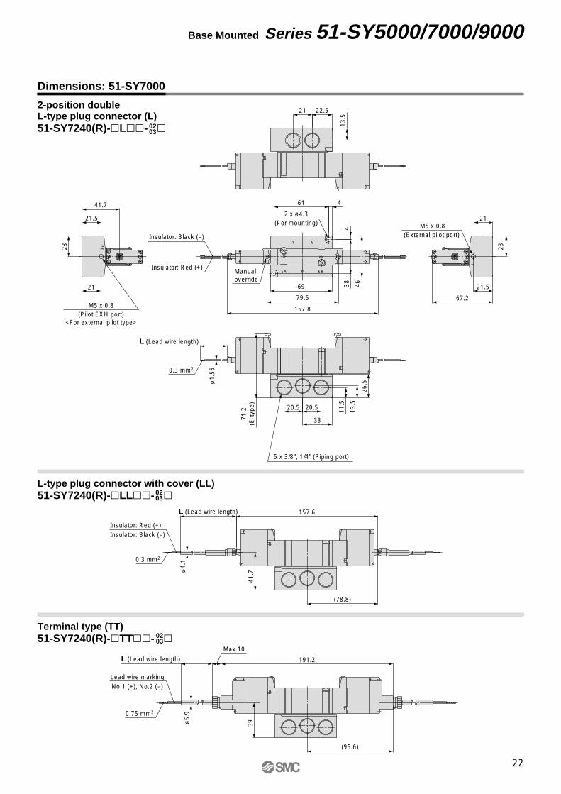
Dimensions: 51-SY7000
2-position doubleL-type plug connector (L)51-SY7240(R)-�L��- �
L-type plug connector with cover (LL)51-SY7240(R)-�LL��- �
Terminal type (TT)51-SY7240(R)-�TT��- �
22
Base Mounted Series 51-SY5000/7000/9000
ø5.
9
Max. 10
L (Lead wire length)
(95.6)
(78.8)
191.2
ø4.
1
41.7
L (Lead wire length) 157.6
13.5
26.5
11.5
20.5 20.5
33
ø1.
55
L (Lead wire length)
71.2
(E-t
ype)
21
23
41.7
21.5
21.5
67.2
23
21
167.8
79.6
69 384
46
461
13.5
21 22.5
0.75 mm2
Lead wire markingNo.1 (+), No.2 (–)
0.3 mm2
Insulator: Red (+)Insulator: Black (–)
5 x 3/8", 1/4" (Piping port)
0.3 mm2
M5 x 0.8(Pilot EXH port)
<For external pilot type>
M5 x 0.8(External pilot port)
Insulator: Red (+)
Insulator: Black (–)
Manual override
2 x ø4.3(For mounting)
PE
B
AP
BA
EBEA
X
39
0203
0203
0203
51-SY-B.qxd 09.3.18 11:11 AM Page 25

Dimensions: 51-SY7000
345
L-type plug connector with cover (LL)51-SY7 40(R)-�LL��- �
345
Terminal type (TT)51-SY7 40(R)-�TT��- �
345
3-position closed center/exhaust center/pressure centerL-type plug connector (L)51-SY7 40(R)-�L��- �
23
Series 51-SY5000/7000/9000
96.9
44.1
ø5.
9
39
Max. 10
L (Lead wire length)
108.6
91.8
204.2
ø4.
1
41.7
L (Lead wire length) 170.6
13.5
26.5
11.520.5 20.5
33
ø1.
55
L (Lead wire length)
71.2
(E-t
ype)
21
23
41.7
21.5
21.5
67.2
23
21
180.8
92.6
69 384
46
461
13.5
21 22.5
0.75 mm2
Lead wire markingNo.1 (+), No.2 (–)
0.3 mm2
Insulator: Red (+)Insulator: Black (–)
5 x 3/8", 1/4" (Piping port)
0.3 mm2
M5 x 0.8(Pilot EXH port)
<For external pilot type>
M5 x 0.8(External pilot port)
Insulator: Red (+)
Insulator: Black (–)
Manual override
2 x ø4.3(For mounting)
PE
B
AP
BA
EBEA
X
0203
0203
0203
51-SY-B.qxd 09.3.18 11:11 AM Page 26
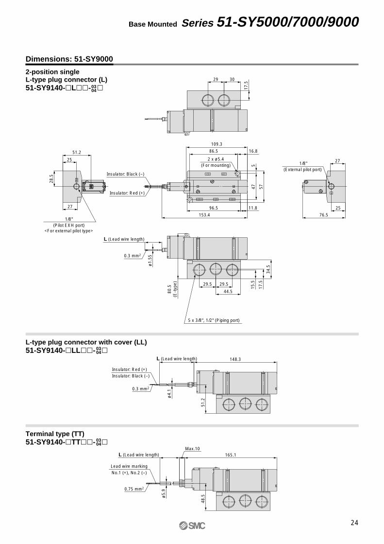
Dimensions: 51-SY9000
0304
Terminal type (TT)51-SY9140-�TT��- �
0304
2-position singleL-type plug connector (L)51-SY9140-�L��- �
0304
L-type plug connector with cover (LL)51-SY9140-�LL��- �
24
Base Mounted Series 51-SY5000/7000/9000
11.8
153.4
16.8
109.3
48.5
Max. 10L (Lead wire length) 165.1
51.2
L (Lead wire length) 148.3
ø4.
1ø
5.9
ø1.
55
L (Lead wire length)
80.5
(E-t
ype)
51.2
76.5
28.5
515
.5
17.5
34.5
29.5 29.5
44.5
25
86.5
5747
96.527 25
27
17.5
29 30
Lead wire markingNo.1 (+), No.2 (–)
Insulator: Red (+)Insulator: Black (–)
0.3 mm2
0.75 mm2
0.3 mm2
Insulator: Red (+)
Insulator: Black (–)
5 x 3/8", 1/2" (Piping port)
A
B
1/8"(Pilot EXH port)
<For external pilot type>
1/8"(External pilot port)
2 x ø5.4(For mounting)
X
4A 2B
EB3P1EA5
PE
51-SY-B.qxd 09.3.18 11:11 AM Page 27

Dimensions: 51-SY9000
0304
Terminal type (TT)51-SY9240-�TT��- �
0304
2-position doubleL-type plug connector (L)51-SY9240-�L��- �
0304
L-type plug connector with cover (LL)51-SY9240-�LL��- �
25
Series 51-SY5000/7000/9000
(108.8)
217.6
(92)
184
76.5
27
25
194.2
106
48.5
Max. 10
L (Lead wire length)
51.2
L (Lead wire length)
ø4.
1ø
5.9
ø1.
55
L (Lead wire length)
80.5
(E-t
ype)
51.2
28.5
515
.5
17.5
34.5
29.5 29.5
44.5
25
86.5
574796.527
17.5
29 30
Lead wire markingNo.1 (+), No.2 (–)
Insulator: Red (+)Insulator: Black (–)
0.3 mm2
0.75 mm2
0.3 mm2
Insulator: Red (+)
Insulator: Black (–)
5 x 3/8", 1/2" (Piping port)
A
B
1/8"(Pilot EXH port)
<For external pilot type>
1/8"(External pilot port)
2 x ø5.4(For mounting)
X
4A 2B
EB3P1EA5
PE
51-SY-B.qxd 09.3.18 11:11 AM Page 28

26
51-SY-B.qxd 09.3.18 11:11 AM Page 29

Type 20
Example
Intrinsically Safe Explosion-proof System5 Port Solenoid Valve
Bar Stock TypeBody Ported ManifoldSeries 51-SY5000/7000
20SS5Y51 055
Add the valve and option part number under the manifold base part number. In the case of complex arrangement, specify them on the manifold specification sheet.
How to Order Manifold How to Order Valve Manifold Assembly
Explosion-proof
57
Manifold series51-SY5000
51-SY7000
Nil
00F00N00T
Rc
G
NPT
NPTF
Thread type
02
20
2 stations
20 stations
Stations
51-SS5Y5-20-05 ·········· 1 set (Type 20, 5 station manifold base part no.)SY5000-26-20A ··········· 1 set (Blanking plate assembly part no.)51-SY5120-ALL3-01 ····· 2 sets (Single solenoid part no., barrier is attached)51-SY5220-ALL3-01 ····· 2 sets (Double solenoid part no., barrier is attached)
∗∗∗
The asterisk denotes the symbol for assembly. Prefix it to the part nos. of the solenoid valve, etc.
∗ This also includes the number of blanking plate assemblies.
51Intrinsically safe explosion-proof structure
Double solenoid51-SY5220-ALL3-01 (2 sets)
Single solenoid51-SY5120-ALL3-01 (2 sets)
Blanking plate assembly
SY5000-26-20A (1 set)
Manifold base (5 stations)51-SS5Y5-20-05
Cylinder port size
01: 1/8"
Stations ····· 3 2 1
27
51-SY-B.qxd 09.3.18 11:11 AM Page 30

A5 1 LL 3SY51 20 01
Explosion-proof
57
51-SY5000
51-SY7000
Series
Symbol Port size Applicable series
51-SY5000
51-SY7000
1/8
1/4
Thread pipingA, B port size
0102
How to Order Valve
12345
2-position single
2-position double
3-position closed center
3-position exhaust center
3-position pressure center
Type of actuation
ABD
Z728.H (51-SYE100-A)
MTL728P + (51-SYE100-B)
MTL5021 (51-SYE100-D)
System Note 1) Note 2)
36
10152030
100
Symbol Lead wire length
300 mm
600 mm
1000 mm
1500 mm
2000 mm
3000 mm
10000 mm
Note
—
Maximum length 600 mm for L-type
—
—
—
—
Semi-standard
Lead wire length
Nil
FNT
Rc
G
NPT
NPTF
Thread type
Nil
DE
Non-locking push type
Push-turn locking slotted type
Push-turn locking lever type
Manual override
Note) When placing an order for body ported solenoid valve as a single unit, mounting screws and a gasket for manifold are not attached. Order them separately, if necessary. (For details, refer to page 32.)
One-touch fittingSymbol
C4C6C8C8C10
Port size Applicable series
ø4 one-touch fitting
ø6 one-touch fitting
ø8 one-touch fitting
ø8 one-touch fitting
ø10 one-touch fitting
51-SY5000
51-SY7000
If a resin tube is used, take measures against static electricity.
Warning
Symbol
L
Electrical entry
L-type plug connector
Electrical entry
Note) The lead wire of TT-type is connected to the terminal block.
LL
L-type plug connector with cover
TT Note)
Terminal type
Note 1) Attached barrier typeThe numbers in ( ), 51-SYE100-� represents SMC’s control number.
Note 2) If the barrier is not necessary due to valve replacement etc, enter O after the system symbol.Example) 51-SY5120-AOLL3-01
51Intrinsically safe explosion-proof structure
28
Body Ported Series 51-SY5000/7000
51-SY-B.qxd 09.3.18 11:11 AM Page 31

29
Series 51-SY5000/7000
Manifold Specifications
Model
Applicable valve
Manifold type
P (SUP)/R (EXH)
Valve stations
A, B port location
Port size
Manifold base mass W (g)n: Stations
P, EA, EB port
A, B port
Single base B mount
Common SUP/EXH
2 to 20 stations Note 1)
Valve
1/4
1/8C4 (ø4 one-touch fitting)C6 (ø6 one-touch fitting)C8 (ø8 one-touch fitting)
W = 36n + 64
1/4C8 (ø8 one-touch fitting)
C10 (ø10 one-touch fitting)
W = 43n + 64
51-SS5Y5-20
51-SY5�20
51-SS5Y7-20
51-SY7�20
Note 1) For 10 stations or more (5 stations or more for the 51-SS5Y7), supply pressure to P port on both sides and exhaust from EA/EB port on both sides.
Note 2) Refer to “Manifold Options” on page 32.
Flow-rate Characteristics
Note) The value is for manifold base with 5 stations and individually operated 2-position type.
51-SS5Y5-20
51-SS5Y7-20
Model
Port size Flow-rate characteristics
1→4/2 (P→A/B) 4/2→5/3 (A/B→EA/EB)1, 5, 3(P, EA, EB)
4, 2(A, B)
1/4
1/4
C8
C10
0.28
0.31
1.9
3.6
C [dm3/(s·bar)] b Cv C [dm3/(s·bar)] b Cv
0.48
0.93
2.2
3.6
0.20
0.27
0.53
0.88
If a resin tube is used, take measures against static electricity.Warning
51-SY-B.qxd 09.3.18 11:11 AM Page 32

30
Body Ported Series 51-SY5000/7000
Stations n 2 stations
60
40
3 stations
76
56
4 stations
92
72
5 stations
108
88
6 stations
124
104
7 stations
140
120
8 stations
156
136
9 stations
172
152
10 stations
188
168
11 stations
204
184
12 stations
220
200
13 stations
236
216
14 stations
252
232
15 stations
268
248
16 stations
284
264
17 stations
300
280
18 stations
316
296
19 stations
332
312
20 stations
348
328
L1L2
Stationsn 2 1
156
143.
4
71.7
L (L
ead
wire
leng
th)
67
41.7
189.
6
177
88.5
Max
. 10
L (L
ead
wire
leng
th)
67
39
67
36.2
41.7
26.5
BA A
B
AB
AB
32.7
153.
6
76.8
32.3
20
16.2
10L2
L1
22
L16
6.2
32.7
45.3
1/8"{A(4), B(2) port}
Manual override
4 x ø4.5(Mounting hole)
(Pitch)P = 16
(Le
ad w
ire le
ngth
)
EA
EB
P
EA
EB
P
71 (E-type)
59.5
16.5
11.5
60
30
2121
{1/8"}
6 x 1/4"{P(1), EA(5), EB(3) port}
Dimensions: 51-SY5000
L-type plug connector (L)51-SS5Y5-20- -�Stations
L-type plug connector with cover (LL)51-SS5Y5-20- -�
Terminal type (TT)51-SS5Y5-20- -�Stations Stations
51-SY-B.qxd 09.3.18 11:11 AM Page 33

31
Series 51-SY5000/7000
Stations n 2 stations
66
46
3 stations
85
65
4 stations
104
84
5 stations
123
103
6 stations
142
122
7 stations
161
141
8 stations
180
160
9 stations
199
179
10 stations
218
198
11 stations
237
217
12 stations
256
236
13 stations
275
255
14 stations
294
274
15 stations
313
293
16 stations
332
312
17 stations
351
331
18 stations
370
350
19 stations
389
369
20 stations
408
388
L1L2
170.
6
157.
6
71.7
L (
Lead
wire
leng
th)
67
41.767
39
Max
. 10
204.
2
191.
2
95.6
L (L
ead
wire
leng
th)
67
41.7
38.3
26.5
{P(1), EA(5), EB(3) port}
2121
30
60
16.5
11.5
67
71 (E-type)
6 x 1/4"
{1/4"}
{A(4), B(2) port}
A
B
A
B
A
B
A
B
23.5
83.9
167.
8
L (
Lead
wire
leng
th)
180.
8 39.4
20(A
, B p
ort)
21 (
For
mou
ntin
g)
10L2
L1
39.8
52.8
Manual override
(Pitch)P = 19
EB
EA
P
EA
EB
P
1/4"
Stationsn 2 1
Dimensions: 51-SY7000
L-type plug connector (L)51-SS5Y7-20- -�
L-type plug connector with cover (LL)51-SS5Y7-20- -�
Terminal type (TT)51-SS5Y7-20- -�Stations Stations
Stations
4 x ø4.5
(Mounting hole)
51-SY-B.qxd 09.3.18 11:11 AM Page 34

Gasket
Round head combination screw
t
EXH port(Both sides)
P1
1
5E5
EXH port(Both sides)
SUP port
t
SUP port
� Type 20 Blanking Plate Assembly
� Individual EXH Spacer Assembly
Series Assembly part no.
51-SY500051-SY7000
SY5000-26-20A
SY7000-26-22A
� Gasket Assembly Part No.
Series Gasket assembly
51-SY500051-SY7000
SY5000-GS-1
SY7000-GS-1
When mounting a valve or spacer on the manifold base or sub-plate, etc., those mounting directions are determined. If mounted in the wrong direction, the equipment to be connected may cause malfunction. Refer to external dimensions, and then mount it.
Warning
Caution ∗ Thread typeRc
G
NPT
NPTF
Nil
FNT
� Individual SUP Spacer Assembly+ Individual EXH Spacer Assembly(Double spacer)
Note) Gasket assembly consists of 10 sets of mounting screws and a gasket.
Manifold Options
� Individual SUP Spacer Assembly
Series Assembly part no.
51-SY500051-SY7000
SY5000-38-1∗A
SY7000-38-1∗A
Port size t1/8
1/4
15
18
Note) The SUP port of the 51-SY5000/7000 may be either on the lead wire side or on the end plate side. (An assembly is shipped under the conditions shown in the figure.)
Portsize
1/8
1/4
Applicablemanifold type
SY5000-75-2∗A
SY7000-73-3∗A
Series
51-SY500051-SY7000
Type 20
Individual SUP +Individual EXHassembly part no.
Note) The SUP spacer's port does not have an orientation. As for the EXH ports, adjust the symbol “5” to the pilot valve side. Also, please make sure to connect the individual ports to protect the wiring section of the pilot valve from drainage, etc.The individual SUP spacer and EXH spacer can be mounted either on the upper side or lower side. (The above illustration shows the condition when the product is shipped out from a factory already assembled.)
Series Assembly part no.
SY5000-39-1∗A
SY7000-39-1∗A
Port size t1/8
1/4
15
18
51-SY500051-SY7000
Mounting screw tightening torques
M3: 0.8 N·mM4: 1.4 N·m
32
Body Ported Series 51-SY5000/7000
51-SY-B.qxd 09.3.18 11:11 AM Page 35

Example
Add the valve and option part number under the manifold base part number. In the case of complex arrangement, specify them on the manifold specification sheet.
How to Order Manifold How to Order Valve Manifold Assembly
51-SS5Y5-41-05-01 ····· 1 set (Type 41, 5 station manifold base part no.)51-SY5240-ALL3 ········ 2 sets (Double solenoid part no., barrier is attached)51-SY5140-ALL3 ········ 2 sets (Single solenoid part no., barrier is attached)SY5000-26-20A ·········· 1 set (Blanking plate assembly part no.)
∗∗∗
The asterisk denotes the symbol for assembly. Prefix it to the part nos. of the solenoid valve, etc.
41SS5Y51 055 01
51Intrinsically safe explosion-proof structure
Explosion-proof
51Intrinsically safe explosion-proof structure
51Explosion-proof
5Manifold series
51-SY5000
Nil
FNT
Rc
G
NPT
NPTF
Thread type
02
20
2 stations
20 stations
Stations
Thread pipingSymbol
01Port size Applicable series
1/8 51-SY5000
A, B port size
One-touch fitting (Metric size)Symbol
C6C8
Port size Applicable series
ø6 one-touch fitting
ø8 one-touch fitting
One-touch fitting (Inch size)Symbol
N7N9
Port size Applicable series
ø1/4" one-touch fitting
ø5/16" one-touch fitting
51-SY5000
51-SY5000
Type 41/Compact Type
42SS5Y 055
5Manifold series
51-SY5000
02
Nil
FNT
Rc
G
NPT
NPTF
Thread type
02
20
2 stations
20 stations
Stations
Thread pipingSymbol
02
Port size Applicable series
1/451-SY500051-SY7000
A, B port size
One-touch fitting (Metric size)Symbol
C6C8C10
Port size Applicable series
ø6 one-touch fitting
ø8 one-touch fitting
ø10 one-touch fitting
51-SY5000
51-SY7000
One-touch fitting (Inch size)Symbol
N7N9N11
Port size Applicable series
ø1/4" one-touch fitting
ø5/16" one-touch fitting
ø3/8" one-touch fitting
51-SY5000
51-SY7000
Type 42/External Pilot Capable
If a resin tube is used, take measures against static electricity.
Warning
Type 42
Intrinsically Safe Explosion-proof System5 Port Solenoid Valve
Bar Stock TypeBase Mounted ManifoldSeries 51-SY5000/7000
Type 41
∗ This also includes the number of blanking plate assemblies.
51-SY5140-ALL3 (2 sets)
Single solenoid
Double solenoid
51-SY5240-ALL3 (2 sets)
SY5000-26-20A (1 set)
Blanking plate assembly
32
1
Stations
51-SS5Y5-41-05-01
Manifold base (5 stations)01: 1/8
A, B port size
EBP
EA
A
B
33
51-SY-B.qxd 09.3.18 11:11 AM Page 36

A5 2 LL 3SY51 40
Explosion-proof
57
51-SY5000
51-SY7000
Series
How to Order Valve
12345
2-position single
2-position double
3-position closed center
3-position exhaust center
3-position pressure center
Type of actuation
Nil
RInternal pilot
External pilot
Pilot type
ABD
Z728.H (51-SYE100-A)
MTL728P + (51-SYE100-B)
MTL5021 (51-SYE100-D)
System Note 1) Note 2)
Symbol
36
10152030
100
Lead wire length
300 mm
600 mm
1000 mm
1500 mm
2000 mm
3000 mm
10000 mm
Note
—
Maximum length 600 mm for L-type
—
—
—
—
Semi-standard
Lead wire length
Nil
DE
Non-locking push type
Push-turn locking slotted type
Push-turn locking lever type
Manual override
Symbol
L
Electrical entry
L-type plug connector
Electrical entry
Note) The lead wire of TT-type is connected to the terminal block.
LL
L-type plug connector with cover
TT Note)
Terminal type
51Intrinsically safe explosion-proof structure
Note 1) Attached barrier typeThe numbers in ( ), 51-SYE100-� represents SMC’s control number.
Note 2) If the barrier is not necessary due to valve replacement etc, enter O after the system symbol.Example) 51-SY5140-AOLL3
34
Base Mounted Series 51-SY5000/7000
51-SY-B.qxd 09.3.18 11:11 AM Page 37

35
Series 51-SY5000/7000
Manifold Specifications
Flow-rate Characteristics
Note) The value is for manifold base with 5 stations and individually operated 2-position type.
Model
Port size Flow-rate characteristics
1→4/2 (P→A/B) 4/2→5/3 (A/B→EA/EB)1, 5, 3(P, EA, EB)
4, 2(A, B)
51-SS5Y5-41
51-SS5Y5-42
51-SS5Y7-42
1/4
1/4
1/4
C8
C8
C10
0.23
0.20
0.25
1.8
1.9
3.0
C [dm3/(s·bar)] b Cv C [dm3/(s·bar)] b Cv
0.44
0.46
0.75
1.9
1.9
3.0
0.16
0.12
0.12
0.45
0.43
0.66
Model
Applicable valve
Manifold type
P (SUP)/R (EXH)
Valve stations
A, B port location
Location
Direction
Port size
Manifold base mass W (g)n: Stations
P, EA, EB port
A, B port
Single base B mount
Common SUP/EXH
2 to 20 stations Note 1)
Base
Side
1/4
1/8
W =61n + 101
51-SS5Y5-41
1/4
W =79n + 127
51-SS5Y5-42
51-SY5�40
1/4C6 (ø6 one-touchfitting)C8 (ø8 one-touchfitting)
C6 (ø6 one-touchfitting)C8 (ø8 one-touchfitting)
C10 (ø10 one-touch fitting)
W =100n + 151
51-SS5Y7-42
51-SY7�40
Note 1) For 10 stations or more (5 stations or more for the 51-SS5Y7), supply pressure to P port on both sides and exhaust from EA/EB port on both sides.
Note 2) Refer to “Manifold Options” on page 39.
51-SY-B.qxd 09.3.18 11:11 AM Page 38

36
Base Mounted Series 51-SY5000/7000
Stations n 2 stations
52.5
42
3 stations
68.5
58
4 stations
84.5
74
5 stations
100.5
90
6 stations
116.5
106
7 stations
132.5
122
8 stations
148.5
138
9 stations
164.5
154
10 stations
180.5
170
11 stations
196.5
186
12 stations
212.5
202
13 stations
228.5
218
14 stations
244.5
234
15 stations
260.5
250
16 stations
276.5
266
17 stations
292.5
282
18 stations
308.5
298
19 stations
324.5
314
20 stations
340.5
330
L1L2
A
B
A
B
A
B
A
B
18
2027
.88.
5
52.6
166.
2
4011
3.6
654.
5
L15.5 L2
(Pitch)P = 16
4 x ø4.5
(Mounting hole)
Manualoverride
15.2
13.8
77.5 (E-type)
2020
37.8
66.8
6 x 1/4"{P(1), EA(5), EB(3) port}
Stations 1 n2
73.5
45.5
Max
. 10
189.
6
125.
351
.7
64.3
L (
Lead
wire
leng
th)
73.5
48.2
156
113.
6
40
L (
Lead
wire
leng
th)
Dimensions: 51-SY5000
L-type plug connector (L)51-SS5Y5-41- -��
L-type plug connector with cover (LL)51-SS5Y5-41- -��
Terminal type (TT)51-SS5Y5-41- -��
9(Pitch)P = 1615.5
7.5
23
42.7
48.2
73.5
2n x 1/8"{A(4), B(2) port}
33
Stations
Stations Stations
L (Lead wire length)
51-SY-B.qxd 09.3.18 11:11 AM Page 39

37
Series 51-SY5000/7000
Stations n 2 stations
59.5
49.5
3 stations
77
67
4 stations
94.5
84.5
5 stations
112
102
6 stations
129.5
119.5
7 stations
147
137
8 stations
164.5
154.5
9stations
182
172
10 stations
199.5
189.5
11 stations
217
207
12 stations
234.5
224.5
13 stations
252
242
14 stations
269.5
259.5
15 stations
287
277
16 stations
304.5
294.5
17 stations
322
312
18 stations
339.5
329.5
19 stations
357
347
20 stations
374.5
364.5
L1L2
82.3 (E-type)
2020
2423
.6
39
68
(Pilot EXH port)<When using external pilot
solenoid valve>
M5 x 0.8
M5 x 0.8(External pilot port)
6 x 1/4"
{P(1), EA(5), EB(3) port}
A
B
A
B
A
B
A
B
65.4
5.3
109.
733
.7
L15
6 2029
7.3
46.3
L1L25
21
Manual override
(Lea
dw
irele
ngth
)
(Pitch)P = 17.5
50.3
82.3 (E-type)
Max
. 10
189.
6
109.
750
.5
63.1
L (L
ead
wire
leng
th)
53
82.3 (E-type)
156
46.3
109.
733
.7L
(Lea
d w
ire le
ngth
)
F
Stations 1 n2
Dimensions: 51-SY5000
L-type plug connector (L)51-SS5Y5-42- -��
L-type plug connector with cover (LL)51-SS5Y5-42- -��
Terminal type (TT)51-SS5Y5-42- -��
19
8.5
53
47.5
37.8
27.3
9.8 2n x 1/4"
{A(4), B(2) port}(Pitch)P = 17.5
17.6
Stations
Stations Stations
51-SY-B.qxd 09.3.18 11:11 AM Page 40
38
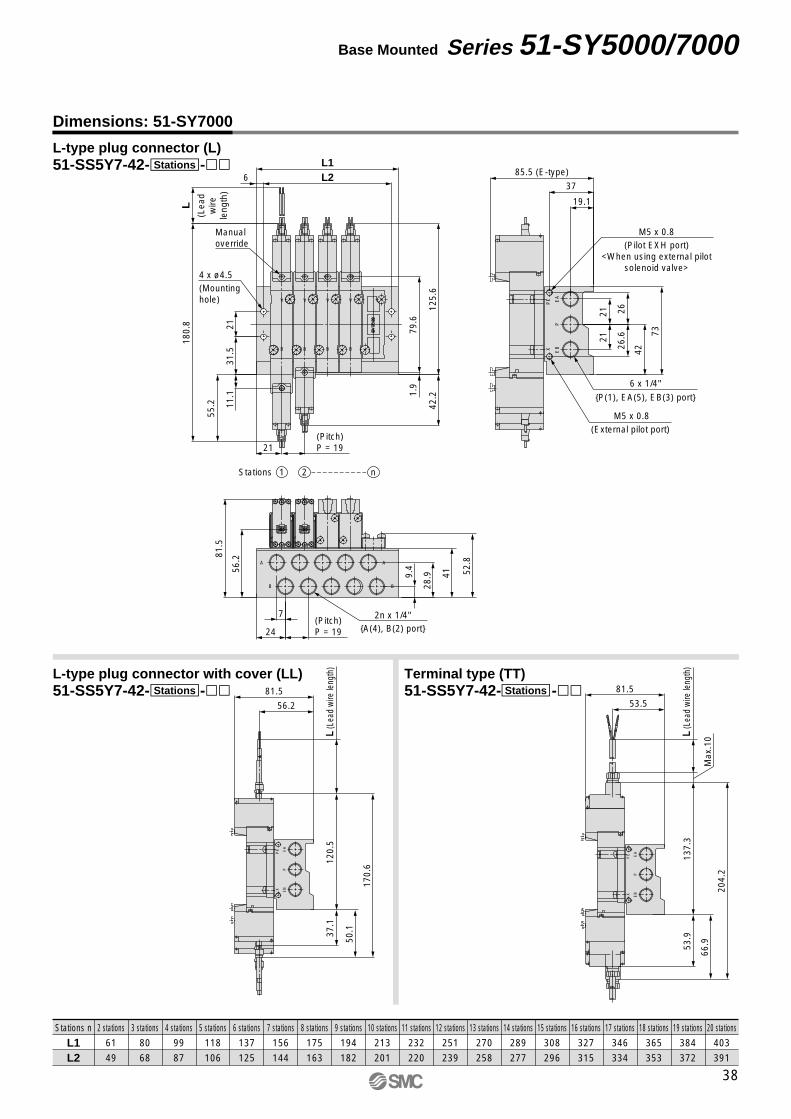
Base Mounted Series 51-SY5000/7000
Stations n 2 stations
61
49
3 stations
80
68
4 stations
99
87
5 stations
118
106
6 stations
137
125
7 stations
156
144
8 stations
175
163
9 stations
194
182
10 stations
213
201
11 stations
232
220
12 stations
251
239
13 stations
270
258
14 stations
289
277
15 stations
308
296
16 stations
327
315
17 stations
346
334
18 stations
365
353
19 stations
384
372
20 stations
403
391
L1L2
XP
E
EB
PE
A
56.2
81.5
170.
6
50.1
120.
537
.1L
(Lea
d w
ire le
ngth
)
XP
E
EB
PE
A
53.5
81.5
Max
. 10
204.
2
137.
353
.9
66.9
L (L
ead
wire
leng
th)
2n x 1/4"{A(4), B(2) port}
81.5
56.2
52.8
41
7
24
28.99.
4
(Pitch)P = 19
A
B B
A
85.5 (E-type)
37
19.1
26.6
262121
42
73
M5 x 0.8(External pilot port)
XP
E
EB
PE
A
6 x 1/4"
{P(1), EA(5), EB(3) port}
M5 x 0.8(Pilot EXH port)
<When using external pilotsolenoid valve>
B
A
B
A
B
A
B
A
1.9
79.6
125.
642
.2
55.2 11
.131
.5
L18
0.8
6 L2L1
21
21(Pitch)P = 19
Manualoverride
4 x ø4.5(Mountinghole)
Stations 1 n2
(Lea
dw
irele
ngth
)
Dimensions: 51-SY7000
L-type plug connector (L)51-SS5Y7-42- -��
L-type plug connector with cover (LL)51-SS5Y7-42- -��
Terminal type (TT)51-SS5Y7-42- -��
Stations
Stations Stations
51-SY-B.qxd 09.3.18 11:11 AM Page 41

Round head combination screw
Gaskett
SUP port
EXH port
t
P
1
E5
SUP port
EXH port
� Type 41, 42 Blanking Plate Assembly
� Individual EXH Spacer Assembly
� Gasket Assembly Part No.
∗ Thread typeRc
G
NPT
NPTF
Nil
FNT
� Individual SUP Spacer Assembly+ Individual EXH Spacer Assembly(Double spacer)
Series Gasket assembly
51-SY500051-SY7000
SY5000-GS-2
SY7000-GS-2
Note) Gasket assembly consists of 10 sets of mounting screws and a gasket.
Manifold Options
Series Assembly part no.
SY5000-39-16∗A
SY7000-39-16∗A
Port size t1/8
1/4
15
18
51-SY500051-SY7000
� Individual SUP Spacer Assembly
Series Assembly part no.
51-SY500051-SY7000
SY5000-38-16∗A
SY7000-38-16∗A
Port size t1/8
1/4
15
18
Note) The SUP port of the 51-SY5000/7000 may be either on the lead wire side or on the end plate side. (An assembly is shipped under the conditions shown in the figure.)
Port size
1/8
1/4
SY5000-75-1∗A
SY7000-73-1∗A
Series
51-SY500051-SY7000
Individual SUP +Individual EXHassembly part no.
Note) The port on a spacer can be directed to the pilot valve side or end plate side. For mounting the port to the pilot valve side, please make sure to connect the ports to protect the pilot valve wiring section from drainage.The individual SUP spacer and EXH spacer can be mounted either on the upper side or lower side. (The above illustration shows the condition when the product is shipped out from a factory already assembled.)
Warning
Caution
Series Assembly part no.
51-SY500051-SY7000
SY5000-26-20A
SY7000-26-22A
Applicable fittings size ød Model A L DKQ2P-06KQ2P-08KQ2P-10KQ2P-07KQ2P-09KQ2P-11
8
10
12
8.5
10
11.5
35
39
43
35
39
43
18
20.5
22
18
20.5
22
6
8
10
1/4"
5/16"
3/8"
Dimensions
� Plug (White) These are inserted in unused cylinder ports and SUP, EXH ports.Purchasing order is available in units of 10 pieces.
øD
L
A
ød
Mounting screw tightening torques
M3: 0.8 N·mM4: 1.4 N·m
When mounting a valve or spacer on the manifold base or sub-plate, etc., those mounting directions are determined. If mounted in the wrong direction, the equipment to be connected may cause malfunction. Refer to external dimensions, and then mount it.
39
Series 51-SY5000/7000
51-SY-B.qxd 09.3.18 11:11 AM Page 42

40
Base Mounted Series 51-SY5000/7000
� How to Order Interface Regulator
ARBY5000-00-�-2 ARBY5000-M1-�-2
Series 51-SY5000
ARBY5000 00 P 2
ARBY7000-00-�-2 ARBY7000-M1-�-2
Caution
Manifold Options
00M1
Pressure gauge (G15-10-01)
Plug (M-5P)
Pressure gaugeconnection port
PA1B1
P port
A port (P controlled, A regulated)
B port (P controlled, B regulated)
Regulating port
Series 51-SY7000
ARBY7000 00 P 2
00M1
Pressure gauge (G15-10-01)
Plug (M-5P)
Pressure gaugeconnection port
PA1B1
P port
A port (P controlled, A regulated)
B port (P controlled, B regulated)
Regulating port
Series Round head combination screw
ARBY5000ARBY7000
M3 x 48.5 (Flat nickel plated)
M4 x 57 (Flat nickel plated)
Gasket
SX5000-57-6
SX7000-57-4
Accessory
Mounting screw tightening torques
M3: 0.8 N·mM4: 1.4 N·m
51-SY-B.qxd 09.3.18 11:11 AM Page 43

Zener Diode Barrier DimensionsSeries 51-SY
41
51-SYE100-B
51-SYE100-A
12.5 115
110
R
BarrierSafe
Z728
.H
HazardousArea/
Ex-Berelch X3
7
8
2
1
5 6
7 8
1 2
3 4
>P
C<
Safe Area/Nicht
Ex-Bereich
UnspecifiedequipmentV 250V
Terminal No. indication (Non-hazardous side)
Barrier input: 24 VDC ±10%
Terminal for ground (2 parts)(M3 Round head combination screw)
Examination certificate emblem
(Examination certificate No. TC14452)
Terminal No.8: +Terminal No.7: –
Terminal No. indication (Hazardous side)
Terminal No.1: +Terminal No.2: –
Terminal: No.7 Terminal: No.8Terminal: No.2 Terminal: No.1
DIN rail mountable (width: 35 mm, recommended thickness: 1.2 mm)
61.5
7.5
7.5
49.2
25
14.2
93.5
85
Hazardous
area tmnls
34
21
728P
+
2 1728P+
MTL 728P+Shunt-diode safety barrier
SafeHaz
4
3
2
1
Terminal No. indication (Non-hazardous side)
Barrier input: 24 VDC(21.6 to 24.5 VDC)
+2%–10
Terminal No.1: +Terminal No.2: –
Terminal: No.1
Terminal: No.2
11.5
Terminal: No.3
Terminal: No.4
Terminal No. indication (Hazardous side)
Terminal No.3: +Terminal No.4: –
Examination certificate emblem
(Examination certificate No. TC14453)
Terminal for ground (with M nut)(Terminal for earth bus bar mounting)
Manufacturer: Pepperl+FuchsNote) See P+F’s catalog for options.
Manufacturer: Measurement Technology Ltd.Note) See MTL Instruments' catalog for
options.
51-SY-B.qxd 09.3.18 11:11 AM Page 44

Insulating Barrier DimensionsSeries 51-SY
42
51-SYE100-D
16
104.3
110
A
-
-
+
+
O/P
MTL5021
HAZARDOUS AREA SAFE AREA
SOLENOID,ALARMOR OTHR IS DEVICE
ToMTL5220(optional)
20-35VDC11
12
3
2
1
SAFE AREAHAZ.AREA
- 11 121 2 3
Terminal No. indication (Non-hazardous side)
Barrier input: 24 VDC ±10%Terminal No.11: –Terminal No.12: +
DIN rail mounted part (width: 35 mm)
Examination certificate emblem
(Examination certificate No. TC14455)
Terminal plug (2 parts)Removable in direction A.
Terminal No. indication (Hazardous side)
Terminal No.2: +Terminal No.1: –
Terminal: No.11
LED: Red (Power supply input indication)
Terminal: No.12
Terminal: No.2
Terminal: No.1
Manufacturer: Measurement Technology Ltd.Note) See MTL Instruments' catalog for
options.
51-SY-B.qxd 09.3.18 11:11 AM Page 45

Safety InstructionsThese safety instructions are intended to prevent hazardous situations and/or equipment damage. These instructions indicate the level of potential hazard with the labels of “Caution,” “Warning” or “Danger.” They are all important notes for safety and must be followed in addition to International Standards (ISO/IEC)∗1), and other safety regulations.∗1) ISO 4414: Pneumatic fluid power – General rules relating to systems.
ISO 4413: Hydraulic fluid power – General rules relating to systems.IEC 60204-1: Safety of machinery – Electrical equipment of machines. (Part 1: General requirements)ISO 10218-1: Manipulating industrial robots - Safety.etc.
1. The compatibility of the product is the responsibility of the person who designs the equipment or decides its specifications.Since the product specified here is used under various operating conditions, its compatibility with specific equipment must be decided by the person who designs the equipment or decides its specifications based on necessary analysis and test results. The expected performance and safety assurance of the equipment will be the responsibility of the person who has determined its compatibility with the product. This person should also continuously review all specifications of the product referring to its latest catalog information, with a view to giving due consideration to any possibility of equipment failure when configuring the equipment.
2. Only personnel with appropriate training should operate machinery and equipment.The product specified here may become unsafe if handled incorrectly. The assembly, operation and maintenance of machines or equipment including our products must be performed by an operator who is appropriately trained and experienced.
3. Do not service or attempt to remove product and machinery/equipment until safety is confirmed.1. The inspection and maintenance of machinery/equipment should only be performed after measures to prevent falling
or runaway of the driven objects have been confirmed. 2. When the product is to be removed, confirm that the safety measures as mentioned above are implemented and the
power from any appropriate source is cut, and read and understand the specific product precautions of all relevant products carefully.
3. Before machinery/equipment is restarted, take measures to prevent unexpected operation and malfunction.
4. Contact SMC beforehand and take special consideration of safety measures if the product is to be used in any of the following conditions. 1. Conditions and environments outside of the given specifications, or use outdoors or in a place exposed to direct
sunlight.2. Installation on equipment in conjunction with atomic energy, railways, air navigation, space, shipping, vehicles, military,
medical treatment, combustion and recreation, or equipment in contact with food and beverages, emergency stop circuits, clutch and brake circuits in press applications, safety equipment or other applications unsuitable for the standard specifications described in the product catalog.
3. An application which could have negative effects on people, property, or animals requiring special safety analysis. 4. Use in an interlock circuit, which requires the provision of double interlock for possible failure by using a mechanical
protective function, and periodical checks to confirm proper operation.
Warning
Caution:
Danger :
Warning:
Caution indicates a hazard with a low level of risk which, if not avoided, could result in minor or moderate injury.
Danger indicates a hazard with a high level of risk which, if not avoided, will result in death or serious injury.
Warning indicates a hazard with a medium level of risk which, if not avoided, could result in death or serious injury.
Back page 1
51-SY-B.qxd 09.3.18 11:11 AM Page 46
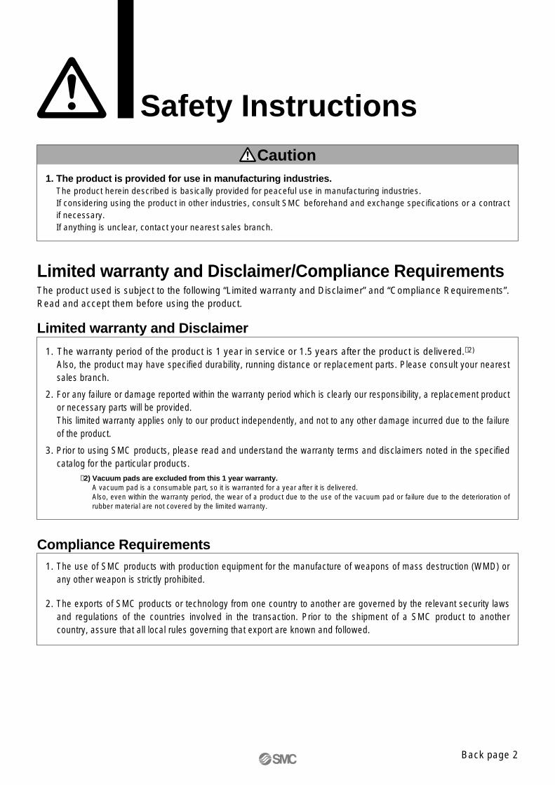
Safety Instructions
Limited warranty and Disclaimer/Compliance Requirements The product used is subject to the following “Limited warranty and Disclaimer” and “Compliance Requirements”.Read and accept them before using the product.
1. The product is provided for use in manufacturing industries.The product herein described is basically provided for peaceful use in manufacturing industries. If considering using the product in other industries, consult SMC beforehand and exchange specifications or a contract if necessary. If anything is unclear, contact your nearest sales branch.
Caution
Limited warranty and Disclaimer
1. The warranty period of the product is 1 year in service or 1.5 years after the product is delivered.∗2)
Also, the product may have specified durability, running distance or replacement parts. Please consult your nearest sales branch.
2. For any failure or damage reported within the warranty period which is clearly our responsibility, a replacement product or necessary parts will be provided. This limited warranty applies only to our product independently, and not to any other damage incurred due to the failure of the product.
3. Prior to using SMC products, please read and understand the warranty terms and disclaimers noted in the specified catalog for the particular products.
∗2) Vacuum pads are excluded from this 1 year warranty.A vacuum pad is a consumable part, so it is warranted for a year after it is delivered. Also, even within the warranty period, the wear of a product due to the use of the vacuum pad or failure due to the deterioration of rubber material are not covered by the limited warranty.
Compliance Requirements1. The use of SMC products with production equipment for the manufacture of weapons of mass destruction (WMD) or
any other weapon is strictly prohibited.
2. The exports of SMC products or technology from one country to another are governed by the relevant security laws and regulations of the countries involved in the transaction. Prior to the shipment of a SMC product to another country, assure that all local rules governing that export are known and followed.
Back page 2
51-SY-B.qxd 09.3.18 11:11 AM Page 47

Series 51-SY5000/7000/9000 Specific Product Precautions 1Be sure to read before handling.Refer to back pages 1 and 2 for Safety Instructions, “Handling Precautions for SMC Products” (M-E03-3) for 3/4/5 Port Solenoid Valves Precautions.
� Push-turn locking lever type [Type E]While pressing, turn it the direction of the arrow.If it is not turned, it can be operated the same way as the non-locking type.
Locked position
Locked position
Manual Override
PUSH
LOCK
PUSH
LOCK
The 51-SY series pilot valve and main valve share a common ex-haust inside the valve. Therefore, do not block the exhaust port when arranging the piping.
Series 51-SY5000/7000/9000Used as a 3-Port Valve
Caution
CautionWhen locking the manual override on the push-turn locking types (D, E), be sure to push it down before turning.Turning without first pushing it down can cause damage to the manual override and trouble such as air leakage, etc.
� Push-turn locking slotted type [Type D]While pressing, turn in the direction of the arrow.If it is not turned, it can be operated the same way as the non-locking type.
� Non-locking push type [Standard]Press in the direction of the arrow.
WarningExhaust Side
Caution
Caution
When operating the locking type D with a screwdriver, turn it gently using a watchmaker’s screwdriver.[Torque: Less than 0.1 N·m]
In case of using a 5-port valve as a 3-port valveThe 51-SY5000/7000/9000 series can be used as normally closed (N.C.) or normally open (N.O.) 3-port port valves by clos-ing one of the cylinder ports (A or B) with a plug. However, they should be used with the exhaust ports kept open.
Plug positionType of actuation
Single
Double
B portN.C.
A portN.O.
How to Use Plug Connector
Caution1. Attaching and detaching connectors• To attach a connector, hold the lever and connector unit be-
tween your fingers and insert straight onto the pins of the sole-noid valve so that the lever’s pawl is pushed into the groove and locks.
• To detach a connector, remove the pawl from the groove by pushing the lever downward with your thumb, and pull the con-nector straight out.
Cover
Lever Groove
Pin
Plug connector with cover
Plug connector
DC polar indication
Num
ber
of s
olen
oids
Plug
Plug
Plug
Plug
Back page 3
51-SY-B.qxd 09.3.18 11:11 AM Page 48
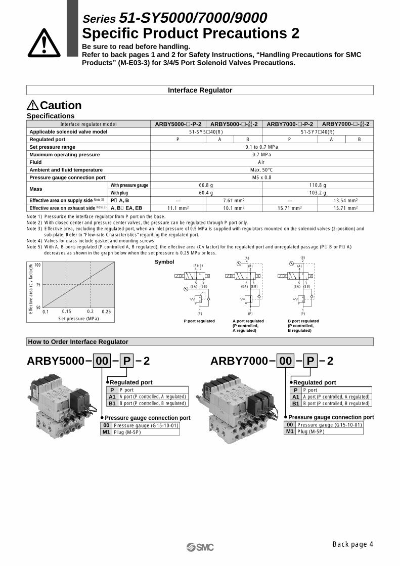
How to Order Interface Regulator
Specifications
Note 1) Pressurize the interface regulator from P port on the base.Note 2) With closed center and pressure center valves, the pressure can be regulated through P port only.Note 3) Effective area, excluding the regulated port, when an inlet pressure of 0.5 MPa is supplied with regulators mounted on the solenoid valves (2-position) and
sub-plate. Refer to “Flow-rate Characteristics” regarding the regulated port.Note 4) Valves for mass include gasket and mounting screws.Note 5) With A, B ports regulated (P controlled A, B regulated), the effective area (Cv factor) for the regulated port and unregulated passage (P→B or P→A)
decreases as shown in the graph below when the set pressure is 0.25 MPa or less.
ARBY5000 00 P 2
(A)4
(A)4
(A)4
(B)2
(B)2
(B)2
(EB)
1(P)
1(P)
1(P)
(EA)
Symbol
P port regulated A port regulated (P controlled, A regulated)
B port regulated (P controlled, B regulated)
5 3(EB)(EA)
5 3(EB)(EA)
5 3
0.1 0.15 0.2 0.25
100
75
50
Set pressure (MPa)
ARBY7000 00 P 2
Interface Regulator
Pressure gauge (G15-10-01)Plug (M-5P)
00M1
Pressure gauge connection portPressure gauge (G15-10-01)Plug (M-5P)
00M1
Pressure gauge connection port
P port A port (P controlled, A regulated)B port (P controlled, B regulated)
PA1B1
Regulated portP port A port (P controlled, A regulated)B port (P controlled, B regulated)
PA1B1
Regulated port
Interface regulator model
Applicable solenoid valve model
Regulated port
Set pressure range
Maximum operating pressure
Fluid
Ambient and fluid temperature
Pressure gauge connection port
Mass
Effective area on supply side Note 3)
Effective area on exhaust side Note 3)
With pressure gauge
With plug
P→A, B
A, B→EA, EB
P
—
11.1 mm2
7.61 mm2
10.1 mm2
A B
51-SY5�40(R)
0.1 to 0.7 MPa
0.7 MPa
Air
Max. 50°CM5 x 0.8
66.8 g
60.4 g
ARBY5000-�-P-2
P
—
15.71 mm2
13.54 mm2
15.71 mm2
A B
51-SY7�40(R)
110.8 g
103.2 g
ARBY7000-�-P-2ARBY5000-�- -2A1B1 ARBY7000-�- -2A1
B1
Series 51-SY5000/7000/9000 Specific Product Precautions 2Be sure to read before handling.Refer to back pages 1 and 2 for Safety Instructions, “Handling Precautions for SMC Products” (M-E03-3) for 3/4/5 Port Solenoid Valves Precautions.
Caution
Effe
ctiv
e ar
ea (C
v fa
ctor
)%
Back page 4
51-SY-B.qxd 09.3.18 11:11 AM Page 49

Flow-rate Characteristics (Conditions: Inlet pressure 0.7 MPa when 2-position solenoid valve is mounted.)
P regulated (P→A, B)
P regulated (P→A, B)
ARBY5000
ARBY7000 A1 regulated (P→A), B1 regulated (P→B)
Flow rate (l/min (ANR))
0 100 200 300 400 500 600 700
0.60.5
0.4
0.3
0.2
0.1
0
A1 regulated (P→A), B1 regulated (P→B)
Flow rate (l/min (ANR))
0 100 200 300 400 500 600 700
0.60.5
0.4
0.3
0.2
0.1
0
0 200 400 600 800 1000 1200
Flow rate (l/min (ANR))
0.6
0.5
0.4
0.3
0.2
0.1
0
Flow rate (l/min (ANR))
0 200 400 600 800 14001000 1200
0.6
0.5
0.4
0.3
0.2
0.1
0
Series 51-SY5000/7000/9000 Specific Product Precautions 3Be sure to read before handling.Refer to back pages 1 and 2 for Safety Instructions, “Handling Precautions for SMC Products” (M-E03-3) for 3/4/5 Port Solenoid Valves Precautions.
Out
let p
ress
ure
(MP
a)
Out
let p
ress
ure
(MP
a)
Out
let p
ress
ure
(MP
a)
Out
let p
ress
ure
(MP
a)
Back page 5
51-SY-B.qxd 09.3.18 11:11 AM Page 50
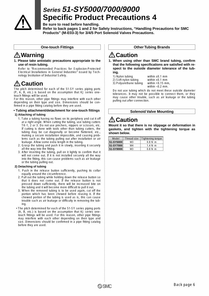
Other Tubing Brands
1. Please take antistatic precautions appropriate to the use of resin tubing.Refer to “Recommended Practices for Explosion-Protected Electrical Installations in General Industries” issued by Tech-nology Institution of Industrial Safety.
One-touch Fittings
The pitch determined for each of the 51-SY series piping ports (P, A, B, etc.) is based on the assumption that KJ series one-touch fittings will be used.For this reason, other pipe fittings may interfere with each other depending on their type and size. Dimensions should be con-firmed in a pipe fitting catalog before they are used.
• Tubing attachment/detachment for one-touch fittings1) Attaching of tubing
1. Take a tubing having no flaws on its periphery and cut it off at a right angle. When cutting the tubing, use tubing cutters TK-1, 2 or 3. Do not use pinchers, nippers or scissors, etc. If cutting is done with tools other than tubing cutters, the tubing may be cut diagonally or become flattened, etc., making a secure installation impossible, and causing prob-lems such as the tubing pulling out after installation or air leakage. Allow some extra length in the tubing.
2. Grasp the tubing and push it in slowly, inserting it securely all the way into the fitting.
3. After inserting the tubing, pull on it lightly to confirm that it will not come out. If it is not installed securely all the way into the fitting, this can cause problems such as air leakage or the tubing pulling out.
2) Detaching of tubing 1. Push in the release button sufficiently, pushing its collar
equally around the circumference.2. Pull out the tubing while holding down the release button so
that it does not come out. If the release button is not pressed down sufficiently, there will be increased bite on the tubing and it will become more difficult to pull it out.
3. When the removed tubing is to be used again, cut off the portion which has been chewed before reusing it. If the chewed portion of the tubing is used as is, this can cause trouble such as air leakage or difficulty in removing the tub-ing.
• The pitch determined for each of the 51-SY series piping ports (A, B, etc.) is based on the assumption that KJ series one-touch fittings will be used. For this reason, other pipe fittings may interfere with each other depending on their type and size. Dimensions should be confirmed in a pipe fitting catalog before they are used.
1. When using other than SMC brand tubing, confirm that the following specifications are satisfied with re-spect to the outside diameter tolerance of the tub-ing.1) Nylon tubing within ±0.1 mm 2) Soft nylon tubing within ±0.1 mm 3) Polyurethane tubing within +0.15 mm,
within –0.2 mm.Do not use tubing which do not meet these outside diameter tolerances. It may not be possible to connect them, or they may cause other trouble, such as air leakage or the tubing pulling out after connection.
Solenoid Valve Mounting
Mount it so that there is no slippage or deformation in gaskets, and tighten with the tightening torque as shown below.
Model Thread size51-SY500051-SY700051-SY9000
M3M4M3
Tightening torque0.8 N·m1.4 N·m0.8 N·m
Series 51-SY5000/7000/9000 Specific Product Precautions 4Be sure to read before handling.Refer to back pages 1 and 2 for Safety Instructions, “Handling Precautions for SMC Products” (M-E03-3) for 3/4/5 Port Solenoid Valves Precautions.
Warning
Caution
Caution
Caution
Back page 6
51-SY-B.qxd 09.3.18 11:11 AM Page 51

Valve Selection for Hazardous Environment
The explosion-proof performance of the 51-SY (intrinsically safe explosion-proof system) is ExiaIIBT4 (See the reference “Explosion-proof Structure Symbol (ExiaIIBT4)”). Selection of a valve for a dangerous place should be done in accordance with “Recommended Practices for Explosion-Protected Electrical Installations in General Industries” issued by Technology Institution of Industrial Safety.
This valve should be used in a class-1 or class-2 environment by combining with a barrier (placed in non-hazardous location).
Note that this valve can not be used in a class-0 envir-onment.
Classification of hazardous environment� Class-0 environment ·········· Not availableA place where an explosive atmosphere is constantly generated or can be generated.Also, a place where atmosphere is above the lower limit of explo-sion constantly or for a long time of period is also regarded as the class-0 environment for safety season.
(Places often falling into the class-0 environment)a) A container of flammable liquid or space above the liquid level
in the container.b) Around the liquid level of flammable liquid in an open container
or similar place.� Class-1 environment ·········· AvailableA place where an explosive atmosphere can be generated peri-odically or occasionally.Also, a place which can have a dangerous concentration of ex-plosive gas due to repair, maintenance, or leakage.
(Places often falling into the class-1 environment)a) Around an opening which releases explosive gas due to re-
moval of a product during normal operation, opening/closing of a lid, or operation of a safety valve.
b) Around the opening of a container such as a tanker and drum which is filled with flammable liquid.
c) Around an opening which releases explosive gas due to occa-sional operation of a relief valve.
d) Around the opening of a gas-vent on a tank etc.e) Around an opening which releases explosive gas during in-
spection or repair work. f) A room or a place which can have explosive gas due to insuffi-
cient ventilation. g) The part which is above the roof of a floating roof tank but
within the shell.h) A place which can have leaked explosive gas and can accu-
mulate the gas such as a pit.� Class-2 environment ·········· AvailableA place where explosive atmosphere can be generated under ab-normal condition though an explosive atmosphere cannot be generated under normal condition.1) A place where flammable gas is constantly operated, but it is
enclosed in an air-tight container or facility, and concentration of the gas may be thick when the container or facility gets broken due to an accident or when operation fails.
2) A place that can have a dangerous explosive gas concentra-tion due to the breakage of mechanical ventilation equipment though the equipment is usually reliable.
Classification of Hazardous Environment
(Places often falling into the class-2 environment)a) A place where dangerous gas or liquid can leak from a con-
tainer if the container is corroded.b) A place where dangerous gas or liquid can be released or leak
out due to incorrect operation of equipment or an abnormal re-action of equipment after exposure to high temperature and high pressure.
c) A place where a dangerous atmosphere is generated due to failure of mandatory ventilation equipment and stagnation of explosive gas.
d) A place which is indoors around or next to the class-1 environ-ment and rarely has explosive gas with dangerous concentra-tion.
Wiring of intrinsically safe explosion-proof circuits should not be routed with the other circuits. Also, it should not have electrostatic induction or electromag-netic induction.
Intrinsically Safe Explosion-proof Circuit Wiring
Disassembling the pilot valve and barrier can deterior-ate the explosion-proof performance, and it may lead to an accident.Therefore, please do not disassemble or modify the pilot valve and barrier.
Prohibition of Disassembly and Modification
Series 51-SY5000/7000/9000 Specific Product Precautions 5Be sure to read before handling.Refer to back pages 1 and 2 for Safety Instructions, “Handling Precautions for SMC Products” (M-E03-3) for 3/4/5 Port Solenoid Valves Precautions.
Warning
Warning
Warning
Warning
Back page 7
51-SY-B.qxd 09.3.18 11:11 AM Page 52

Explosion-proof Structure Symbol (ExiaIIBT4)
(1) Groups of explosion-proof equipmentExplosion-proof equipment is classified into two groups de-pending on the place where electric equipment is used. Group I: Electric equipment which is used in a dangerous en-
vironment within a tunnel or mineGroup II: Electric equipment which is used in a dangerous en-
vironment within a factory or office.SMC valve belongs to Group II.
(2) Classification of gasClassification of gas corresponds to the explosion class of gas specified in the conventional standard, and there are three classes, A, B, and C, depending on the characteristics of explosive gas. The classification of gas specifies the dan-gerous degree as C>B>A. SMC valve is applicable to the ga-ses classified into A and B.
(3) Temperature classTemperature class corresponds to the ignition degree of gas specified in the conventional standard, and there are six clas-ses, T1 to T6. T1 is the least dangerous gas which has the highest ignition temperature, and T6 is the most dangerous gas which has the lowest ignition temperature. SMC valve is applicable to T1 to T4 temperature classes.
Symbols Specified by Technical Standard
ia
Type of explosion-proof structure: Intrinsically safe explosion-proof structure (system)
Ex
A symbol of the explosion-proof structure based on Technical Standard (rev.)
Group: IIClassification of gas: Gas of A and B
Temperature classification: Gas of T1 to T4
T4
Reference
Series 51-SY5000/7000/9000 Specific Product Precautions 6Be sure to read before handling.Refer to back pages 1 and 2 for Safety Instructions, “Handling Precautions for SMC Products” (M-E03-3) for 3/4/5 Port Solenoid Valves Precautions.
Back page 8
51-SY-B.qxd 09.3.18 11:11 AM Page 53

51-SY-B.qxd 09.3.18 11:11 AM Page 54

51-SY-B.qxd 09.3.18 11:11 AM Page 55

Safety Instructions Be sure to read “Handling Precautions for SMC Products” (M-E03-3) before using.
∗ Deleted the system “C” and “E” from How to Order on page 1, 14, 28, 34.
∗ Deleted the 51-SYE100-C from Zener Diode Barrier Dimensions on page 41.
∗ Deleted the 51-SYE100-E from Insulating Barrier Dimensions on page 42. NQ
Record of changes
Edition B
51-SY-B.qxd 09.3.18 11:11 AM Page 56