
Intraground N1 Series Control Stations - Emerson · Intraground™ N1 Series Control Stations...
15
NEC — N1 Series (Non-Factory Sealed): Class I, Division 1 and 2, Groups C, D NEMA 3R, 4X, 7CD, 12 Intraground ™ N1 Series Control Stations Nonmetallic 10 Amp, 600 Vac Max. for Heavy Duty Use. Applications • Listed for use in Class I, Division 1 and 2, Group C and D atmospheres such as: — Diethyl ether — Methyl ethyl keytone — Acetone — Toluene — No. 3 fuel oil — Ammonium hydroxide (20%) — Benzene — Regular unleaded gas — Ethyl acetate — Hexane — Methanol • Not suitable for: — Ethylene dichloride — Partially halogenated hydrocarbons • Sealing fittings must be field installed adjacent to enclosure on all conduit runs. • Explosionproof, with sealing fittings installed at each conduit entrance, the N1 Series enclosures withstood a hydrostatic test of four times the maximum internal explosion pressure that could be developed from a gas or vapor explosion. • Push buttons and selector switches are used in conjunction with contactors or magnetic starters for remote control of motors in hazardous locations. They provide circuit control and/ or selection. • Pilot lights provide visual assurance that an electrical function is being performed at a remote or local hazardous location. Features • Nonmetallic construction with metal imbedded grounding grid. No need to install special wires and parts for grounding. Feed-thru or dead-end grounded 1/2” or 3/4” conduit openings for threaded conduit. • Special grounding wire furnished with each box provides safe grounding when cover is removed. • Ideal for use in corrosive environments. Nonmetallic enclosures with corrosion resistant parts coated with epoxy, Teflon ® or Mylar ® , these control stations offer unsurpassed resistance to chemicals. • Unique labyrinth-path construction assures flame-tight joint between body and cover. • Silicone gasket, specially designed for the labyrinth-path joint, prevents entrance of moisture without interfering with the venting of cooled hazardous gases and vapors. • Typical mechanical properties of 24,500 psi tensile strength, 3% elongation at break, 33,000 psi flexural strength, and 1,200,000 psi flexural modulus. • Electrical properties of sample specimens: dielectric strength (in air) of 769 at 1/16”. • High strength thermoplastic polyetherimide, together with thick walls (5/16”) and sound structural design (rounded corners) provides superior resistance to impact and crushing. • Excellent resistance to ultraviolet light and water. • Excellent conduit connection strength. • Excellent resistance to attack by fungi and mold. • Superior flammability resistance. Related Products • Sealing fitting must be installed at each conduit entrance of the N1 enclosure to be explosionproof. See Hazardous Location Fittings Section. Push Button Pilot Light Selector Switch Combination Push Button and Pilot Light Combination Selector Switch and Pilot Light For Class I, Division 1 applications, sealing fittings must be field installed adjacent to enclosure on all conduit runs. Teflon and Mylar are registered trademarks of E. I. du Pont de Nemours and Company. CONTROLS: NEC/CEC EXPLOSIONPROOF CONTROL STATIONS AND SWITCHES Visit our website at www.emerson.com or contact us at (800) 621-1506. © June 2017 107
Transcript of Intraground N1 Series Control Stations - Emerson · Intraground™ N1 Series Control Stations...
NEC — N1 Series (Non-Factory Sealed): Class I, Division 1 and 2, Groups C, D NEMA 3R, 4X, 7CD, 12
Intraground™ N1 Series Control StationsNonmetallic10 Amp, 600 Vac Max. for Heavy Duty Use.
Applications• Listed for use in Class I, Division 1 and 2, Group C and D
atmospheres such as:— Diethyl ether— Methyl ethyl keytone— Acetone— Toluene— No. 3 fuel oil— Ammonium hydroxide (20%)— Benzene— Regular unleaded gas— Ethyl acetate— Hexane— Methanol
• Not suitable for:— Ethylene dichloride— Partially halogenated hydrocarbons
• Sealing fittings must be field installed adjacent to enclosure on all conduit runs.
• Explosionproof, with sealing fittings installed at each conduit entrance, the N1 Series enclosures withstood a hydrostatic test of four times the maximum internal explosion pressure that could be developed from a gas or vapor explosion.
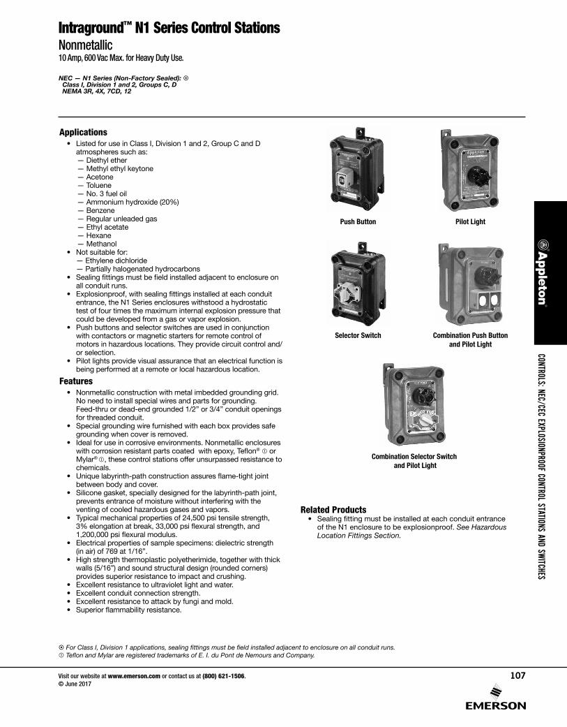
• Push buttons and selector switches are used in conjunction with contactors or magnetic starters for remote control of motors in hazardous locations. They provide circuit control and/or selection.
• Pilot lights provide visual assurance that an electrical function is being performed at a remote or local hazardous location.
Features• Nonmetallic construction with metal imbedded grounding grid.
No need to install special wires and parts for grounding. Feed-thru or dead-end grounded 1/2” or 3/4” conduit openings for threaded conduit.
• Special grounding wire furnished with each box provides safe grounding when cover is removed.
• Ideal for use in corrosive environments. Nonmetallic enclosures with corrosion resistant parts coated with epoxy, Teflon® or Mylar® , these control stations offer unsurpassed resistance to chemicals.
• Unique labyrinth-path construction assures flame-tight joint between body and cover.
• Silicone gasket, specially designed for the labyrinth-path joint, prevents entrance of moisture without interfering with the venting of cooled hazardous gases and vapors.
• Typical mechanical properties of 24,500 psi tensile strength, 3% elongation at break, 33,000 psi flexural strength, and 1,200,000 psi flexural modulus.
• Electrical properties of sample specimens: dielectric strength (in air) of 769 at 1/16”.
• High strength thermoplastic polyetherimide, together with thick walls (5/16”) and sound structural design (rounded corners) provides superior resistance to impact and crushing.
• Excellent resistance to ultraviolet light and water. • Excellent conduit connection strength. • Excellent resistance to attack by fungi and mold.• Superior flammability resistance.
Related Products• Sealing fitting must be installed at each conduit entrance
of the N1 enclosure to be explosionproof. See Hazardous Location Fittings Section.
Push Button Pilot Light
Selector Switch Combination Push Button and Pilot Light
Combination Selector Switch and Pilot Light
For Class I, Division 1 applications, sealing fittings must be field installed adjacent to enclosure on all conduit runs. Teflon and Mylar are registered trademarks of E. I. du Pont de Nemours and Company.
CONTROLS: NEC/CEC EXPLOSIONPROOF CONTROL STATIONS AND SWITCHES
Visit our website at www.emerson.com or contact us at (800) 621-1506. © June 2017
107
NEC — N2 Series (Factory Sealed): Class I, Division 2, Groups B, C, D Class II, Division 1 and 2, Groups E, F, G Class III NEMA 3R, 4X, 9EFG, 12
Intraground™ N2 Series Control StationsNonmetallic10 Ampere, 600 Vac Max. for Heavy Duty Use.
Applications• Listed for use in Class I, Division 2, Group B, C and D
atmospheres such as:— Diethyl ether— Methyl ethyl keytone— Acetone— Toluene— No. 3 fuel oil— Ammonium hydroxide (20%)— Benzene— Regular unleaded gas— Ethyl acetate— Hexane— Methanol.
• Listed for use in Class II, Division 1 and 2, Groups E, F and G.• Dust-tight construction. After 32 hour UL test, no magnesium
dust entered the enclosure.• Push buttons and selector switches are used in conjunction
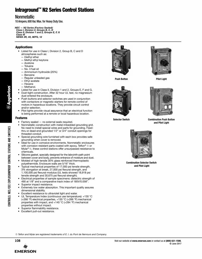
with contactors or magnetic starters for remote control of motors in hazardous locations. They provide circuit control and/or selection.
• Pilot lights provide visual assurance that an electrical function is being performed at a remote or local hazardous location.
Features• Factory sealed — no external seals required.• Nonmetallic construction with metal imbedded grounding grid.
No need to install special wires and parts for grounding. Feed-thru or dead-end grounded 1/2” or 3/4” conduit openings for threaded conduit.
• Special grounding wire furnished with each box provides safe grounding when cover is removed.
• Ideal for use in corrosive environments. Nonmetallic enclosures with corrosion resistant parts coated with epoxy, Teflon® or Mylar® , these control stations offer unsurpassed resistance to chemicals.
• Silicone gasket, specially designed for the labryinth-path point between cover and body, prevents entrance of moisture and dust.
• Molded of high-tensile 30% glass reinforced thermoplastic polyethermide. Enclosure walls are 5/16” thick.
• Typical mechanical properties of 17,000 psi tensile strength, 3% elongation at break, 27,000 psi flexural strength, and 1,100,000 psi flexural modulus (UL tests showed 18,918 psi tensile strength and 30,675 psi flexural strength).
• Electrical properties of sample specimens: dielectric strength of 490 at 1/8” and a comparative track index of 185V/0.058”.
• Superior impact resistance. • Extremely low water absorption. This important quality assures
dimensional stability.• Excellent resistance to ultraviolet light and water. • UL Temperature Index (continuous use temperature): +130 °C
(+266 °F) electrical properties, +130 °C (+266 °F) mechanical properties with impact, and +140 °C (+284 °F) mechanical properties without impact.
• Superior flammability resistance. • Excellent pull-out resistance.
Push Button Pilot Light
Selector Switch Combination Push Button and Pilot Light
Combination Selector Switch and Pilot Light
Teflon and Mylar are registered trademarks of E. I. du Pont de Nemours and Company.
CONT
ROLS
: NEC
/CEC
EXP
LOSI
ONPR
OOF
CONT
ROL
STAT
IONS
AND
SW
ITCHE
S
Visit our website at www.emerson.com or contact us at (800) 621-1506. © June 2017
108
NEC — N1 Series (Non-Factory Sealed): Class I, Division 1 and 2, Groups C, D NEMA 3R, 4X, 7CD, 12
NEC — N2 Series (Factory Sealed): Class I, Division 2, Groups B, C, D Class II, Division 1 and 2, Groups E, F, G Class III NEMA 3R, 4X, 9EFG, 12
Intraground™ N1 and N2 Series Control StationsNonmetallic10 Ampere, 600 Vac Max. for Heavy Duty Use.
Features• Heavy duty push button, 10 Amp 600 Vac rated.• Dozens of possible combinations of push buttons, pilot lights
and selector switches.• Smooth, rounded integral bushing in each conduit opening
protects conduct or insulation.• Accurately tapped, tapered conduit openings for tight, rigid
joints and ground continuity.• Push Buttons, Selector Switches, and Pilot Lights
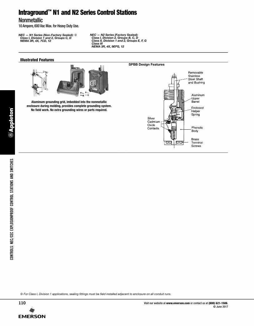
— Stainless steel push button shaft operates within stainless steel bushing, assuring long, maintenance-free operation.
— Push button and selector switch contacts are silver cadmium oxide which are ”sealed” in lower phenolic chamber isolated from corrosive elements. Assures positive contact and long, trouble-free operation.
— Enclosed stainless steel helper spring prevents accidental operation of push button in severe vibration installations.
— Corrosion resistant stainless steel Teflon® coated hex head cap screws hold covers to body.
— Push buttons are supplied with lockout type guards as standard. Hole in guard will accept locks with up to 1/4” hasp. Permits locking of push button to prevent unauthorized operation.
— Clearly marked terminals with brass screws assure quick, easy wiring.
— Pilot light supplied with jewel/guard assembly and 120 Vac, 6 Watt type 6S6 lamp, 120 Vac/Vdc, 50/60 Hz, 6 Watt.
Standard Materials• Body and cover: 30% glass-reinforced thermoplastic
polyetherimide• SPBB push button: aluminum upper barrel and phenolic lower
barrel with nylon plastic button. Glass reinforced polypropylene guard. Silicone weather boot. Aluminum nameplate
• SPLS pilot light: aluminum guard and body assembly; steel clamping ring; and tempered glass jewel
• SSBA selector switch: aluminum housing, nylon knobs and cams, and sealed phenolic contact block
• NBN rectangular button with weather boot: Nylon plastic button with neoprene weather boot. Aluminum nameplate
• NMRB mushroom button with weather boot: anodized aluminum buttons with neoprene weather boot
• Selector switch locking devices and push button securing rods: stainless steel
• Cover bolts: stainless steel• Nameplates: copperfree (4/10 of 1% max.) aluminum• Receptacles: copperfree (4/10 of 1% max.) aluminum
Standard Finishes• Cover bolts: Teflon® • Nameplates: Mylar® • Pilot light guard and clamping ring: epoxy
Options• Three position selector switches with modified operation. For
description and switch diagram, refer to switch operators.— Momentary contact right position, spring return to center,
maintained contact left position. Add suffix –SRC.— Momentary contact left position, spring return to center,
maintained contact right position. Add suffix –SLC.• Alternate contacts add suffix –ALT.• Selector switch Lockout: locks 2- or 3-position handle in any
position. Suffix –LD.• Push button front operated mushroom head (momentary
contact): — Red –NMRBRE— Green –NMRBGR— Black, add suffix –NMRBBL.
• Pilot light jewel/guard assembly. Order by suffixes if color desired is other than red, as follows: — Amber –JGBA— Blue –JGBB— Clear –JGBC— Green –JGBG— Opal –JGBO
• For colored LED jewel/guard assembly, order by suffixes: — Red –LEDR— Green –LEDG— Amber –LEDA
• Pilot light transformers for single pilot light per gang. Order by suffix:
Primary Voltage Lamp Voltage Suffix220 120 TR-2277 120 TR-3440 120 TR-4550 120 TR-5
• Securing rod for push button lockout guard. Add suffix –SR.• NPBRKT nameplate mounting bracket to make circuit
description/identification easy.— Pre-drilled holes in bottom of bracket allow direct mounting
to control stations with existing cover bolts.— Pre-drilled holes in middle of bracket allow mounting of
customer’s circuit identification nameplate; epoxy glue may also be used for mounting (phenolic nameplate not included).
— Bracket eliminates costly field installation of drilling and tapping to accommodate circuit identification nameplate.
— Brackets fit side-by-side on 2-, 3- and 4-gang boxes and 3-devices.
NEC Certifications and Compliances• UL Standards: UL 508, UL 698, UL 1203 • UL Listed: E10449, E81751
For Class I, Division 1 applications, sealing fittings must be field installed adjacent to enclosure on all conduit runs. Teflon and Mylar are registered trademarks of E. I. du Pont de Nemours and Company.
CONTROLS: NEC/CEC EXPLOSIONPROOF CONTROL STATIONS AND SWITCHES
Visit our website at www.emerson.com or contact us at (800) 621-1506. © June 2017
109
NEC — N1 Series (Non-Factory Sealed): Class I, Division 1 and 2, Groups C, D NEMA 3R, 4X, 7CD, 12
NEC — N2 Series (Factory Sealed): Class I, Division 2, Groups B, C, D Class II, Division 1 and 2, Groups E, F, G Class III NEMA 3R, 4X, 9EFG, 12
Intraground™ N1 and N2 Series Control StationsNonmetallic10 Ampere, 600 Vac Max. for Heavy Duty Use.
Illustrated FeaturesSPBB Design Features
Aluminum grounding grid, imbedded into the nonmetallic enclosure during molding, provides complete grounding system.
No field work. No extra grounding wires or parts required.
For Class I, Division 1 applications, sealing fittings must be field installed adjacent to enclosure on all conduit runs.
CONT
ROLS
: NEC
/CEC
EXP
LOSI
ONPR
OOF
CONT
ROL
STAT
IONS
AND
SW
ITCHE
S
Visit our website at www.emerson.com or contact us at (800) 621-1506. © June 2017
110
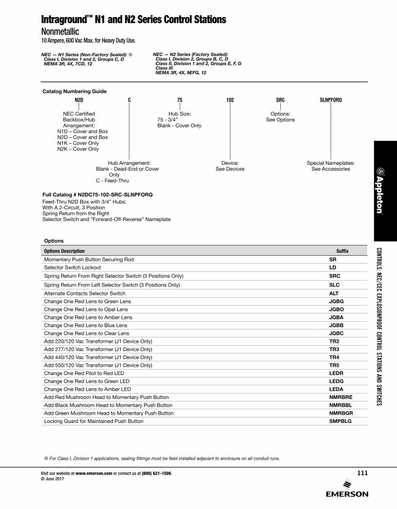
Options
Options Description Suffix
Momentary Push Button Securing Rod SR
Selector Switch Lockout LD
Spring Return From Right Selector Switch (3 Positions Only) SRC
Spring Return From Left Selector Switch (3 Positions Only) SLC
Alternate Contacts Selector Switch ALT
Change One Red Lens to Green Lens JGBG
Change One Red Lens to Opal Lens JGBO
Change One Red Lens to Amber Lens JGBA
Change One Red Lens to Blue Lens JGBB
Change One Red Lens to Clear Lens JGBC
Add 220/120 Vac Transformer (J1 Device Only) TR2
Add 277/120 Vac Transformer (J1 Device Only) TR3
Add 440/120 Vac Transformer (J1 Device Only) TR4
Add 550/120 Vac Transformer (J1 Device Only) TR5
Change One Red Pilot to Red LED LEDR
Change One Red Lens to Green LED LEDG
Change One Red Lens to Amber LED LEDA
Add Red Mushroom Head to Momentary Push Button NMRBRE
Add Black Mushroom Head to Momentary Push Button NMRBBL
Add Green Mushroom Head to Momentary Push Button NMRBGR
Locking Guard for Maintained Push Button SMPBLG
For Class I, Division 1 applications, sealing fittings must be field installed adjacent to enclosure on all conduit runs.
NEC — N1 Series (Non-Factory Sealed): Class I, Division 1 and 2, Groups C, D NEMA 3R, 4X, 7CD, 12
NEC — N2 Series (Factory Sealed): Class I, Division 2, Groups B, C, D Class II, Division 1 and 2, Groups E, F, G Class III NEMA 3R, 4X, 9EFG, 12
Catalog Numbering Guide
N2D C 75 102 SRC SLNPFORQ
NEC Certified Backbox/Hub Arrangement:
N1D – Cover and BoxN2D – Cover and BoxN1K – Cover OnlyN2K – Cover Only
Hub Size:75 - 3/4”Blank - Cover Only
Options: See Options
Hub Arrangement:Blank - Dead-End or Cover
OnlyC - Feed-Thru
Device: See Devices
Special Nameplates:See Accessories
Full Catalog # N2DC75-102-SRC-SLNPFORQFeed-Thru N2D Box with 3/4” Hubs:With A 2-Circuit, 3 PositionSpring Return from the RightSelector Switch and ”Forward-Off-Reverse” Nameplate
Intraground™ N1 and N2 Series Control StationsNonmetallic10 Ampere, 600 Vac Max. for Heavy Duty Use.
CONTROLS: NEC/CEC EXPLOSIONPROOF CONTROL STATIONS AND SWITCHES
Visit our website at www.emerson.com or contact us at (800) 621-1506. © June 2017
111

NEC — N1 Series (Non-Factory Sealed): Class I, Division 1 and 2, Groups C, D NEMA 3R, 4X, 7CD, 12
NEC — N2 Series (Factory Sealed): Class I, Division 2, Groups B, C, D Class II, Division 1 and 2, Groups E, F, G Class III NEMA 3R, 4X, 9EFG, 12
Intraground™ N1 and N2 Series Control Stations DevicesNonmetallic
Devices
Device Description SuffixOne Pilot Light (Red Standard) J1Two Pilot Lights J2One Pilot Light and One Momentary Push Button J1U1One Pilot Light and Two Momentary Push Buttons J1U2One Pilot Light and One Maintained Push Button J1UM1One Pilot Light and One Dust-Cap Push Button J1DU1One Pilot Light and One 12 Selector Switch (2 Position, 2 Circuit) J112One Pilot Light and One 35 Selector Switch (2 Position, 4 Circuit ) J135One Pilot Light and One 102 Selector Switch (3 Position, 2 Circuit) J1102One Pilot Light and One 345 Selector Switch (3 Position, 4 Circuit) J1345One Monetary Push Button U1Two Monetary Push Buttons U2Two Side-By-Side Momentary Push Buttons U2DBLThree Monetary Push Buttons U3One Momentary Push Button and One Maintained Push Button U1UM1One Momentary Push Button and One Dust-Cap Push Button U1DU1One Momentary Push Button and One 12 Selector Switch (2 Position, 2 Circuit) U112One Momentary Push Button and One 35 Selector Switch (2 Position, 4 Circuit ) U135One Momentary Push Button and One 102 Selector Switch (3 Position, 2 Circuit) U1102One Momentary Push Button and One 345 Selector Switch (3 Position, 4 Circuit) U1345One Maintained Push Button (Mushroom Head - Red) UM1Two Maintained Push Button UM2One Maintained and One Dust-Cap Push Button UM1DU1One Maintained Push Button and One 12 Selector Switch (2 Position, 2 Circuit) UM112One Maintained Push Button and One 35 Selector Switch (2 Position, 4 Circuit ) UM135One Maintained Push Button and One 102 Selector Switch (3 Position, 2 Circuit) UM1102One Maintained Push Button and One 345 Selector Switch (3 Position, 4 Circuit) UM1345One Dust Cap Push Button DU1Two Dust Cap Push Buttons DU2One Dust Cap and One 12 Selector Switch (2 Position, 2 Circuit) DU112One Dust Cap and One 35 Selector Switch (2 Position, 4 Circuit ) DU135One Dust Cap and One 102 Selector Switch (3 Position, 2 Circuit) DU1102One Dust Cap and One 345 Selector Switch (3 Position, 4 Circuit) DU1345One 12 Selector Switch (2 Position, 2 Circuit) 12One 35 Selector Switch (2 Position, 4 Circuit ) 35One 102 Selector Switch (3 Position, 2 Circuit) 102One 345 Selector Switch (3 Position, 4 Circuit) 345
For Class I, Division 1 applications, sealing fittings must be field installed adjacent to enclosure on all conduit runs.
CONT
ROLS
: NEC
/CEC
EXP
LOSI
ONPR
OOF
CONT
ROL
STAT
IONS
AND
SW
ITCHE
S
Visit our website at www.emerson.com or contact us at (800) 621-1506. © June 2017
112
NEC — N1 Series (Non-Factory Sealed) : Class I, Division 1 and 2, Groups C, D NEMA 3R, 4X, 7CD, 12
NEC — N2 Series (Factory Sealed): Class I, Division 2, Groups B, C, D Class II, Division 1 and 2, Groups E, F, G Class III NEMA 3R, 4X, 9EFG, 12
Intraground™ N1 and N2 Series Control StationsNonmetallic10 Ampere, 600 Vac Max. for Heavy Duty Use. N1 Series – Neutral Color; N2 Series – Blue Color.
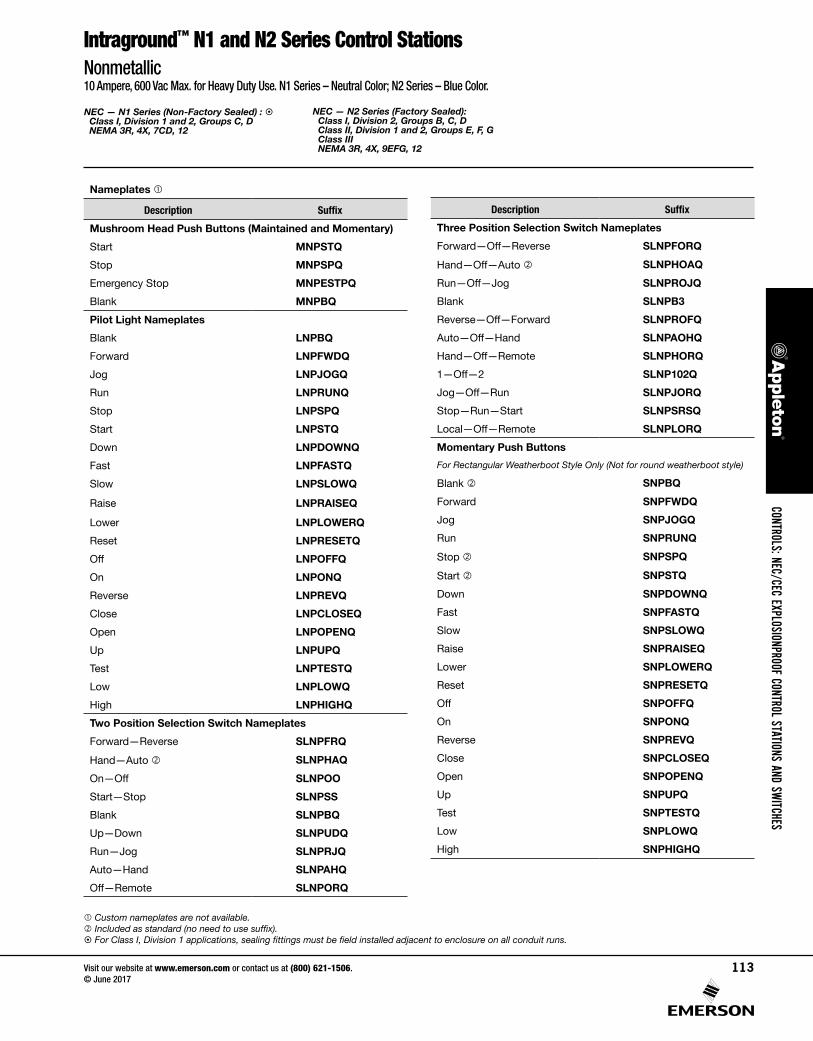
Nameplates
Description Suffix
Mushroom Head Push Buttons (Maintained and Momentary)
Start MNPSTQ
Stop MNPSPQ
Emergency Stop MNPESTPQ
Blank MNPBQ
Pilot Light Nameplates
Blank LNPBQ
Forward LNPFWDQ
Jog LNPJOGQ
Run LNPRUNQ
Stop LNPSPQ
Start LNPSTQ
Down LNPDOWNQ
Fast LNPFASTQ
Slow LNPSLOWQ
Raise LNPRAISEQ
Lower LNPLOWERQ
Reset LNPRESETQ
Off LNPOFFQ
On LNPONQ
Reverse LNPREVQ
Close LNPCLOSEQ
Open LNPOPENQ
Up LNPUPQ
Test LNPTESTQ
Low LNPLOWQ
High LNPHIGHQ
Two Position Selection Switch Nameplates
Forward—Reverse SLNPFRQ
Hand—Auto SLNPHAQ
On—Off SLNPOO
Start—Stop SLNPSS
Blank SLNPBQ
Up—Down SLNPUDQ
Run—Jog SLNPRJQ
Auto—Hand SLNPAHQ
Off—Remote SLNPORQ
Description Suffix
Three Position Selection Switch Nameplates
Forward—Off—Reverse SLNPFORQ
Hand—Off—Auto SLNPHOAQ
Run—Off—Jog SLNPROJQ
Blank SLNPB3
Reverse—Off—Forward SLNPROFQ
Auto—Off—Hand SLNPAOHQ
Hand—Off—Remote SLNPHORQ
1—Off—2 SLNP102Q
Jog—Off—Run SLNPJORQ
Stop—Run—Start SLNPSRSQ
Local—Off—Remote SLNPLORQ
Momentary Push Buttons
For Rectangular Weatherboot Style Only (Not for round weatherboot style)
Blank SNPBQ
Forward SNPFWDQ
Jog SNPJOGQ
Run SNPRUNQ
Stop SNPSPQ
Start SNPSTQ
Down SNPDOWNQ
Fast SNPFASTQ
Slow SNPSLOWQ
Raise SNPRAISEQ
Lower SNPLOWERQ
Reset SNPRESETQ
Off SNPOFFQ
On SNPONQ
Reverse SNPREVQ
Close SNPCLOSEQ
Open SNPOPENQ
Up SNPUPQ
Test SNPTESTQ
Low SNPLOWQ
High SNPHIGHQ
Custom nameplates are not available. Included as standard (no need to use suffix). For Class I, Division 1 applications, sealing fittings must be field installed adjacent to enclosure on all conduit runs.
CONTROLS: NEC/CEC EXPLOSIONPROOF CONTROL STATIONS AND SWITCHES
Visit our website at www.emerson.com or contact us at (800) 621-1506. © June 2017
113
NEC — N1 Series (Non-Factory Sealed): Class I, Division 1 and 2, Groups C, D NEMA 3R, 4X, 7CD, 12
NEC — N2 Series (Factory Sealed): Class I, Division 2, Groups B, C, D Class II, Division 1 and 2, Groups E, F, G Class III NEMA 3R, 4X, 9EFG, 12
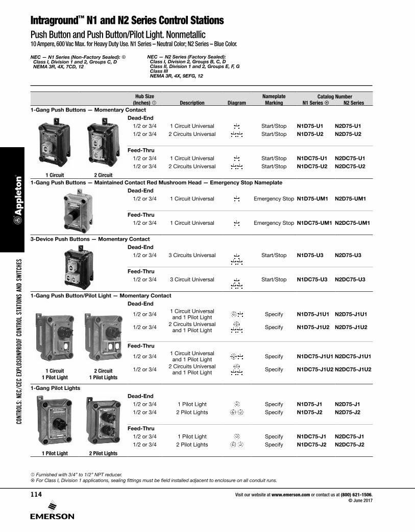
Hub Size (Inches) Description Diagram
Nameplate Marking
Catalog NumberN1 Series N2 Series
1-Gang Push Buttons — Momentary ContactDead-End
1/2 or 3/4 1 Circuit Universal Start/Stop N1D75-U1 N2D75-U11/2 or 3/4 2 Circuits Universal Start/Stop N1D75-U2 N2D75-U2
Feed-Thru1/2 or 3/4 1 Circuit Universal Start/Stop N1DC75-U1 N2DC75-U11/2 or 3/4 2 Circuits Universal Start/Stop N1DC75-U2 N2DC75-U2
1 Circuit 2 Circuit1-Gang Push Buttons — Maintained Contact Red Mushroom Head — Emergency Stop Nameplate
Dead-End1/2 or 3/4 1 Circuit Universal Emergency Stop N1D75-UM1 N2D75-UM1
Feed-Thru1/2 or 3/4 1 Circuit Universal Emergency Stop N1DC75-UM1 N2DC75-UM1
3-Device Push Buttons — Momentary ContactDead-End
1/2 or 3/4 3 Circuits Universal Start/Stop N1D75-U3 N2D75-U3
Feed-Thru1/2 or 3/4 3 Circuit Universal Start/Stop N1DC75-U3 N2DC75-U3
1-Gang Push Button/Pilot Light — Momentary ContactDead-End
1/2 or 3/4 1 Circuit Universal and 1 Pilot Light Specify N1D75-J1U1 N2D75-J1U1
1/2 or 3/4 2 Circuits Universal and 1 Pilot Light Specify N1D75-J1U2 N2D75-J1U2
Feed-Thru
1/2 or 3/4 1 Circuit Universal and 1 Pilot Light Specify N1DC75-J1U1 N2DC75-J1U1
1 Circuit 1 Pilot Light
2 Circuit 1 Pilot Lights
1/2 or 3/4 2 Circuits Universal and 1 Pilot Light Specify N1DC75-J1U2 N2DC75-J1U2
1-Gang Pilot LightsDead-End
1/2 or 3/4 1 Pilot Light Specify N1D75-J1 N2D75-J11/2 or 3/4 2 Pilot Lights Specify N1D75-J2 N2D75-J2
Feed-Thru1/2 or 3/4 1 Pilot Light Specify N1DC75-J1 N2DC75-J11/2 or 3/4 2 Pilot Lights Specify N1DC75-J2 N2DC75-J2
1 Pilot Light 2 Pilot Lights
Furnished with 3/4” to 1/2” NPT reducer. For Class I, Division 1 applications, sealing fittings must be field installed adjacent to enclosure on all conduit runs.
Intraground™ N1 and N2 Series Control Stations Push Button and Push Button/Pilot Light. Nonmetallic10 Ampere, 600 Vac Max. for Heavy Duty Use. N1 Series – Neutral Color; N2 Series – Blue Color.
CONT
ROLS
: NEC
/CEC
EXP
LOSI
ONPR
OOF
CONT
ROL
STAT
IONS
AND
SW
ITCHE
S
Visit our website at www.emerson.com or contact us at (800) 621-1506. © June 2017
114

NEC — N1 Series (Non-Factory Sealed): Class I, Division 1 and 2, Groups C, D NEMA 3R, 4X, 7CD, 12
NEC — N2 Series (Factory Sealed): Class I, Division 2, Groups B, C, D Class II, Division 1 and 2, Groups E, F, G Class III NEMA 3R, 4X, 9EFG, 12
Intraground™ N1 and N2 Series Control StationsSelector Switch Control Stations and Fire Alarm Station. Nonmetallic10 Ampere, 600 Vac Max. for Heavy Duty Use. N1 Series – Neutral Color; N2 Series – Blue Color.
Hub Size (Inches)
Pilot Light
Diagram
Switch Diagram Catalog Number
Left Center RightWith
Pilot LightWith Out
Pilot Light
Dead-End
1/2 or 3/4 — Pilot Light and 2-Pos., 2-Cir. Selector Switch None
N1D75-J112 N1D75-12
N2D75-J112 N2D75-12
1/2 or 3/4 — Pilot Light and 2-Pos., 4-Cir. Selector Switch None
N1D75-J135 N1D75-35
N2D75-J135 N2D75-35
Note: Standard legend plate reads Hand/Auto
1/2 or 3/4 — Pilot Light and 3-Pos., 2-Cir. Selector Switch
N1D75-J1102 N1D75-102
N2D75-J1102 N2D75-102
Pilot Light and Selector Switch 1/2 or 3/4 — Pilot Light and 3-Pos., 4-Cir. Selector Switch
N1D75-J1345 N1D75-345
N2D75-J1345 N2D75-345
Note: Standard legend plate reads Hand/Off/Auto
Feed-Thru
1/2 or 3/4 — Pilot Light and 2-Pos., 2-Cir. Selector Switch None
N1DC75-J112 N1DC75-12
N2DC75-J112 N2DC75-12
1/2 or 3/4 — Pilot Light and 2-Pos., 4-Cir. Selector Switch None
N1DC75-J135 N1DC75-35
N2DC75-J135 N2DC75-35
Note: Standard legend plate reads Hand/Auto
1/2 or 3/4 — Pilot Light and 3Pos., 2-Cir. Selector Switch
N1DC75-J1102 N1DC75-102
N2DC75-J1102 N2DC75-102
Selector Switch 1/2 or 3/4 — Pilot Light and 3-Pos., 4-Cir. Selector Switch
N1DC75-J1345 N1DC75-345
N2DC75-J1345 N2DC75-345
Note: Standard legend plate reads Hand/Off/Auto
Fire Alarm Station, Factory Sealed — Universal Contacts, with hammer on chain
Hub Size (Inches) Description
Catalog NumberN1 Series
(Neutral Color)N2 Series
(Red Color)
Dead-End
1/2 or 3/4 Universal 2 Position, 1 Circuit N1D75FA-U1 N2D75FA-U1
Feed-Thru
1/2 or 3/4 Universal 2 Position, 1 Circuit N1DC75FA-U1 N2DC75FA-U1
Replacement Glass
(For N1 or N2) NFA-G
Furnished with a 3/4” to 1/2” NPT reducer. For Class I, Division 1 applications, sealing fittings must be field installed adjacent to enclosure on all conduit runs. Do not use in atmospheres containing
electrically conductive dusts (most coal dusts are not electrically conductive).
CONTROLS: NEC/CEC EXPLOSIONPROOF CONTROL STATIONS AND SWITCHES
Visit our website at www.emerson.com or contact us at (800) 621-1506. © June 2017
115
NEC — N1 Series (Non-Factory Sealed): Class I, Division 1 and 2, Groups C, D NEMA 3R, 4X, 7CD, 12
NEC — N2 Series (Factory Sealed): Class I, Division 2, Groups B, C, D Class II, Division 1 and 2, Groups E, F, G Class III NEMA 3R, 4X, 9EFG, 12
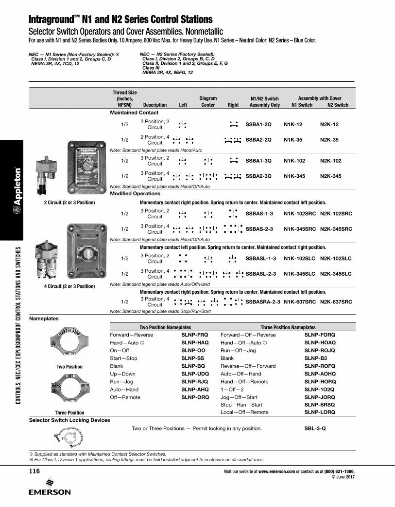
Intraground™ N1 and N2 Series Control StationsSelector Switch Operators and Cover Assemblies. NonmetallicFor use with N1 and N2 Series Bodies Only. 10 Ampere, 600 Vac Max. for Heavy Duty Use. N1 Series – Neutral Color; N2 Series – Blue Color.
Thread Size (Inches, NPSM) Description
Diagram N1/N2 Switch Assembly Only
Assembly with CoverLeft Center Right N1 Switch N2 Switch
Maintained Contact
1/2 2 Position, 2 Circuit SSBA1-2Q N1K-12 N2K-12
1/2 2 Position, 4 Circuit SSBA2-2Q N1K-35 N2K-35
Note: Standard legend plate reads Hand/Auto
1/2 3 Position, 2 Circuit SSBA1-3Q N1K-102 N2K-102
1/2 3 Position, 4 Circuit SSBA2-3Q N1K-345 N2K-345
Note: Standard legend plate reads Hand/Off/Auto
Modified Operations
2 Circuit (2 or 3 Position) Momentary contact right position. Spring return to center. Maintained contact left position.
1/2 3 Position, 2 Circuit SSBAS-1-3 N1K-102SRC N2K-102SRC
1/2 3 Position, 4 Circuit SSBAS-2-3 N1K-345SRC N2K-345SRC
Note: Standard legend plate reads Hand/Off/Auto
Momentary contact left position. Spring return to center. Maintained contact right position.
1/2 3 Position, 2 Circuit SSBASL-1-3 N1K-102SLC N2K-102SLC
1/2 3 Position, 4 Circuit SSBASL-2-3 N1K-345SLC N2K-345SLC
4 Circuit (2 or 3 Position) Note: Standard legend plate reads Auto/Off/Hand
Momentary contact right position. Spring return to center. Maintained contact left position.
1/2 3 Position, 4 Circuit SSBASRA-2-3 N1K-637SRC N2K-637SRC
Note: Standard legend plate reads Stop/Run/Start
Nameplates
Two Position Nameplates Three Position NameplatesForward—Reverse SLNP-FRQ Forward—Off—Reverse SLNP-FORQ
Hand—Auto SLNP-HAQ Hand—Off—Auto SLNP-HOAQ
On—Off SLNP-OO Run—Off—Jog SLNP-ROJQ
Start—Stop SLNP-SS Blank SLNP-B3
Two Position Blank SLNP-BQ Reverse—Off—Forward SLNP-ROFQ
Up—Down SLNP-UDQ Auto—Off—Hand SLNP-AOHQ
Run—Jog SLNP-RJQ Hand—Off—Remote SLNP-HORQ
Auto—Hand SLNP-AHQ 1—Off—2 SLNP-1O2Q
Off—Remote SLNP-ORQ Jog—Off—Start SLNP-JORQStop—Run—Start SLNP-SRSQ
Three Position Local—Off—Remote SLNP-LORQ
Selector Switch Locking Devices
Two or Three Positions — Permit locking in any position. SBL-3-Q
Supplied as standard with Maintained Contact Selector Switches. For Class I, Division 1 applications, sealing fittings must be field installed adjacent to enclosure on all conduit runs.
CONT
ROLS
: NEC
/CEC
EXP
LOSI
ONPR
OOF
CONT
ROL
STAT
IONS
AND
SW
ITCHE
S
Visit our website at www.emerson.com or contact us at (800) 621-1506. © June 2017
116

NEC — N1 Series (Non-Factory Sealed): Class I, Division 1 and 2, Groups C, D NEMA 3R, 4X, 7CD, 12
NEC — N2 Series (Factory Sealed): Class I, Division 2, Groups B, C, D Class II, Division 1 and 2, Groups E, F, G Class III NEMA 3R, 4X, 9EFG, 12
Intraground™ N1 and N2 Series Control StationsNonmetallic. For use with N1 and N2 Series Bodies Only. All Covers Supplied with Four Bolts and Blank Nameplate. N1 Series– Neutral Color; N2 Series– Blue Color.
Covers Only — for Use with Nonmetallic Mounting Bodies Below
DescriptionCatalog Number
N1 Series N2 Series
Pilot Light or Push Button Covers 3/4” tapped openings
One opening: one pilot light or one push button N1K-1PL N2K-1PL
Two openings: two pilot lights; two push buttons — one pilot light and one push button N1K-2PL N2K-2PL
Push Button or Selector Switch Covers 1/2” tapped openings
Two openings: selector switch or two push buttons N1K-2SP N2K-2SP
Push Button, Pilot light or Selector Switch Covers One 3/4” top and two 1/2” bottom tapped openings
One top and two bottom openings — one pilot light, two push buttons; one pilot light, one selector switch; or three push buttons
N1K-3JPB N2K-3JPB
1-Gang Nonmetallic Mounting Bodies — for use with Covers Above
Description Hub Size (Inches) Catalog Number
N1 Series N2 Series
Dead-End 1/2 or 3/4 N1D75Q N2D75Q
Feed-Thru 1/2 or 3/4 N1DC75Q N2DC75Q
Nameplate Mounting Bracket
Description Catalog Number
Bracket for N1, N2 Series NPBRKT-N1N2
To order bracket with control station, add suffix –NPBRKT to end of catalog number.
Note: Secure mount bracket using cover nameplate screws.
Furnished with 3/4” to 1/2” NPSM reducer. Furnished with a 3/4” to 1/2” NPT reducer. For Class I, Division 1 applications, sealing fittings must be field installed adjacent to enclosure on all conduit runs.
CONTROLS: NEC/CEC EXPLOSIONPROOF CONTROL STATIONS AND SWITCHES
Visit our website at www.emerson.com or contact us at (800) 621-1506. © June 2017
117
NEC: Class I, Division 1 and 2, Groups B,C, D Class II, Division 1 and 2, Groups E, F, G Class III
Intraground™ N1 and N2 Series Control StationsNonmetallic10 Ampere, 600 Vac Max. for Heavy Duty Use. N1 Series – Neutral Color; N2 Series – Blue Color.
Description Diagram Catalog Number
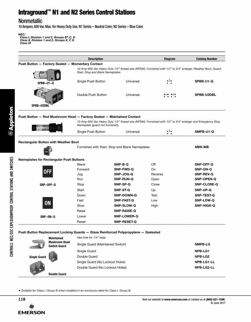
Push Button — Factory Sealed — Momentary Contact
SPBB-U1-Q
SPBB-U2DBL
10 Amp 600 Vac Heavy Duty 1/2” thread size (NPSM). Furnished with 1/2” to 3/4” enlarger, Weather Boot, Guard, Start, Stop and Blank Nameplates.
Single Push Button Universal SPBB-U1-Q
Double Push Button Universal SPBB-U2DBL
Push Button — Red Mushroom Head — Factory Sealed — Maintained Contact 10 Amp 600 Vac Heavy Duty 1/2” thread size (NPSM). Furnished with 1/2” to 3/4” enlarger and Emergency Stop Nameplate (guard not furnished).
Single Push Button Universal SMPB-U1-Q
Rectangular Button with Weather BootFurnished with Start, Stop and Blank Nameplates NBN-WB
Nameplates for Rectangular Push ButtonsBlank SNP-B-Q Off SNP-OFF-QForward SNP-FWD-Q On SNP-ON-QJog SNP-JOG-Q Reverse SNP-REV-QRun SNP-RUN-Q Open SNP-OPEN-Q
SNP-OFF-Q Stop SNP-SP-Q Close SNP-CLOSE-Q
Start SNP-ST-Q Up SNP-UP-Q
Down SNP-DOWN-Q Test SNP-TEST-Q
Fast SNP-FAST-Q Low SNP-LOW-Q
Slow SNP-SLOW-Q High SNP-HIGH-Q
Raise SNP-RAISE-Q
SNP-ON-Q Lower SNP-LOWER-Q
Reset SNP-RESET-Q
Push Button Replacement Locking Guards — Glass Reinforced Polypropylene — Gasketed
Maintained Mushroom Head Switch Guard
Has hole for 1/4” hasp.
Single Guard (Maintained Switch) SMPB-LG
Single Guard NPB-LG1
Single Guard Double Guard NPB-LG2
Single Guard (No Lockout Holes) NPB-LG1-LL
Double Guard (No Lockout Holes) NPB-LG2-LL
Double Guard
Suitable for Class I, Group B when installed in an enclosure rated for Class I, Group B.
CONT
ROLS
: NEC
/CEC
EXP
LOSI
ONPR
OOF
CONT
ROL
STAT
IONS
AND
SW
ITCHE
S
Visit our website at www.emerson.com or contact us at (800) 621-1506. © June 2017
118

NEC: Class I, Division 1 and 2, Groups B,C, D Class II, Division 1 and 2, Groups E, F, G Class III
Intraground™ N1 and N2 Series Control StationNonmetallic10 Ampere, 600 Vac Max. for Heavy Duty Use. N1 Series – Neutral Color; N2 Series – Blue Color.
Push Button Accessories and Parts
Description Catalog Number
Push Button Securing Rod with Chain — Stainless Steel
For use with Single Guard Only NBL-SR
Mushroom Head Button with Weather Boot for Use with Momentary Contact — Gasketed
Black NMRB-BL
Green NMRB-GRRed NMRB-RE
Mushroom Head Push ButtonFor Use with Mushroom Head Push Button — Maintained Contact — Solid-Colored NonmetallicRed NMRBM-RE
Nameplates — Mushroom Head Push Button For Momentary and MaintainedStart MNPSTQStop MNPSPQ
Emergency Stop MNPESTPQ
MNPESTPQ Blank MNPBQ
Pilot Light, Factory Sealed
Incandescent Furnished with 6S6 120 Vac incandescent lamp, jewel and guard. Has 457 mm (18”) long, type SFF-2 pigtail leads; +150 °C (+302 °F). Body has 3/4” straight thread (NPSM).
With Red Jewel SPLSREB
With Green Jewel SPLSGRB
With Amber Jewel SPLSAMB
With Blue Jewel SPLSBLB
With Clear Jewel SPLSCLB
With Opal Jewel SPLSOPB
LEDFurnished with candelabra base 120 Vac LED, jewel and guard. Has 457 mm (18”) long, type SFF-2 pigtail leads; +150 °C (+302 °F). Body has 3/4” straight thread (NPSM).
With Red LED, Clear Jewel SPLNSREB
With Green LED, Clear Jewel SPLNSGRB
Pilot Light Chamber Only With Amber LED, Clear Jewel SPLNSAMB
Chamber Only (Same as above, less jewel, guard and lamp) SPLSSCB
Suitable for Class I, Group B when installed in an enclosure rated for Class I, Group B.
CONTROLS: NEC/CEC EXPLOSIONPROOF CONTROL STATIONS AND SWITCHES
Visit our website at www.emerson.com or contact us at (800) 621-1506. © June 2017
119
NEC: Class I, Division 1 and 2, Groups B,C, D Class II, Division 1 and 2, Groups E, F, G Class III
Intraground™ N1 and N2 Series Control StationsNonmetallic10 Ampere, 600 Vac Max. for Heavy Duty Use. N1 Series – Neutral Color; N2 Series – Blue Color.
Push Button Accessories and Parts
Description Catalog Number
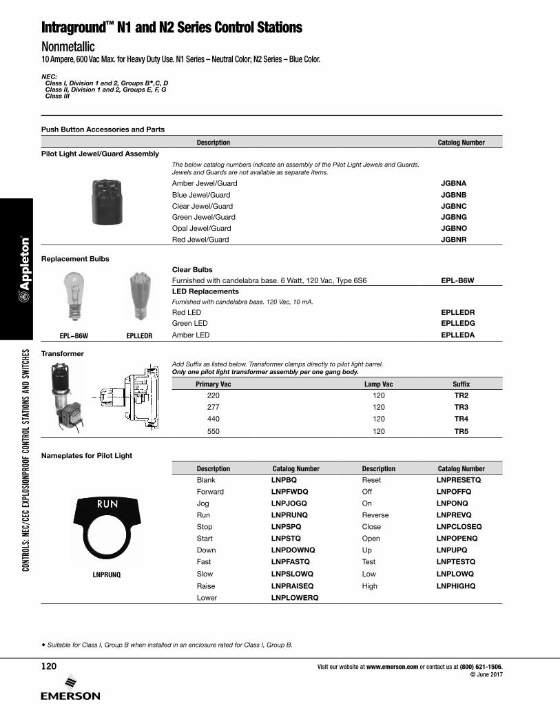
Pilot Light Jewel/Guard AssemblyThe below catalog numbers indicate an assembly of the Pilot Light Jewels and Guards. Jewels and Guards are not available as separate items.
Amber Jewel/Guard JGBNA
Blue Jewel/Guard JGBNB
Clear Jewel/Guard JGBNCGreen Jewel/Guard JGBNG
Opal Jewel/Guard JGBNO
Red Jewel/Guard JGBNR
Replacement BulbsClear BulbsFurnished with candelabra base. 6 Watt, 120 Vac, Type 6S6 EPL-B6WLED ReplacementsFurnished with candelabra base. 120 Vac, 10 mA.
Red LED EPLLEDRGreen LED EPLLEDG
EPL-B6W EPLLEDR Amber LED EPLLEDA
TransformerAdd Suffix as listed below. Transformer clamps directly to pilot light barrel. Only one pilot light transformer assembly per one gang body.
Primary Vac Lamp Vac Suffix
220 120 TR2
277 120 TR3
440 120 TR4
550 120 TR5
Nameplates for Pilot Light
Description Catalog Number Description Catalog Number
Blank LNPBQ Reset LNPRESETQ
Forward LNPFWDQ Off LNPOFFQ
Jog LNPJOGQ On LNPONQ
Run LNPRUNQ Reverse LNPREVQ
Stop LNPSPQ Close LNPCLOSEQ
Start LNPSTQ Open LNPOPENQ
Down LNPDOWNQ Up LNPUPQ
Fast LNPFASTQ Test LNPTESTQ
LNPRUNQ Slow LNPSLOWQ Low LNPLOWQ
Raise LNPRAISEQ High LNPHIGHQ
Lower LNPLOWERQ
Suitable for Class I, Group B when installed in an enclosure rated for Class I, Group B.
CONT
ROLS
: NEC
/CEC
EXP
LOSI
ONPR
OOF
CONT
ROL
STAT
IONS
AND
SW
ITCHE
S
Visit our website at www.emerson.com or contact us at (800) 621-1506. © June 2017
120
NEC — N1 Series (Non-Factory Sealed): Class I, Division 1 and 2, Groups C, D NEMA 3R, 4X, 7CD, 12
NEC — N2 Series (Factory Sealed): Class I, Division 2, Groups B, C, D Class II, Division 1 and 2, Groups E, F, G Class III NEMA 3R, 4X, 9EFG, 12
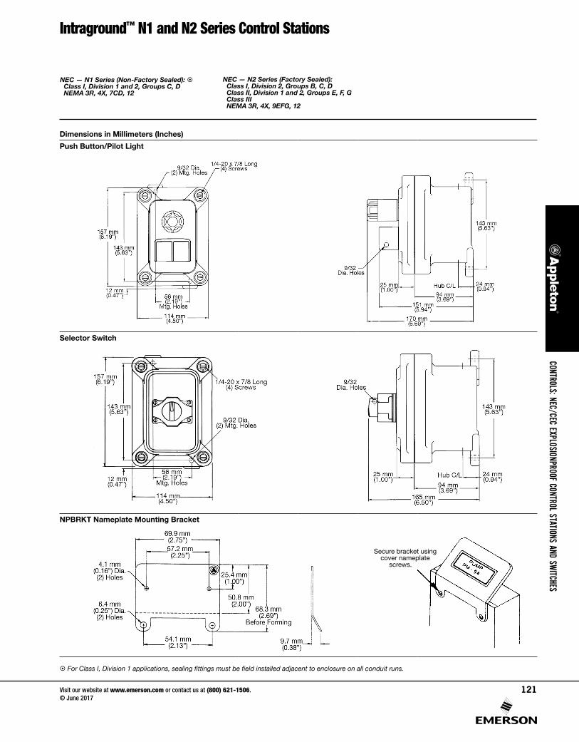
Intraground™ N1 and N2 Series Control Stations
Dimensions in Millimeters (Inches)
Push Button/Pilot Light
Selector Switch
NPBRKT Nameplate Mounting Bracket
Secure bracket using cover nameplate
screws.
For Class I, Division 1 applications, sealing fittings must be field installed adjacent to enclosure on all conduit runs.
CONTROLS: NEC/CEC EXPLOSIONPROOF CONTROL STATIONS AND SWITCHES
Visit our website at www.emerson.com or contact us at (800) 621-1506. © June 2017
121


![V P V U R gq ^ ý u;Vóÿ d u;S:Wßÿ ^ WS S:Wß0]0nÿ ) N …...N N N N N N N N N N N N N N N N N N N N N N N N N N N N N N N N N P N1 N1 N1 N1 N1 N1 N1 N1 N1 N1 N1 N1 P P P N1 N1](https://static.fdocuments.us/doc/165x107/5fbf575d848b0b7e9575f4b2/v-p-v-u-r-gq-uv-d-usw-ws-sw00n-n-n-n-n-n-n-n-n-n.jpg)
![Pandemic Influenza H1 N1 & H5 N1 V2[1]](https://static.fdocuments.us/doc/165x107/546c3dddb4af9f8e2c8b50a1/pandemic-influenza-h1-n1-h5-n1-v21.jpg)


